WO2011121676A1 - 通信装置および通信方法 - Google Patents
通信装置および通信方法 Download PDFInfo
- Publication number
- WO2011121676A1 WO2011121676A1 PCT/JP2010/002402 JP2010002402W WO2011121676A1 WO 2011121676 A1 WO2011121676 A1 WO 2011121676A1 JP 2010002402 W JP2010002402 W JP 2010002402W WO 2011121676 A1 WO2011121676 A1 WO 2011121676A1
- Authority
- WO
- WIPO (PCT)
- Prior art keywords
- pause
- frame
- node
- communication device
- data
- Prior art date
- Legal status (The legal status is an assumption and is not a legal conclusion. Google has not performed a legal analysis and makes no representation as to the accuracy of the status listed.)
- Ceased
Links
Images















Classifications
-
- H—ELECTRICITY
- H04—ELECTRIC COMMUNICATION TECHNIQUE
- H04L—TRANSMISSION OF DIGITAL INFORMATION, e.g. TELEGRAPHIC COMMUNICATION
- H04L12/00—Data switching networks
- H04L12/28—Data switching networks characterised by path configuration, e.g. LAN [Local Area Networks] or WAN [Wide Area Networks]
- H04L12/46—Interconnection of networks
- H04L12/4604—LAN interconnection over a backbone network, e.g. Internet, Frame Relay
- H04L12/462—LAN interconnection over a bridge based backbone
- H04L12/4625—Single bridge functionality, e.g. connection of two networks over a single bridge
-
- H—ELECTRICITY
- H04—ELECTRIC COMMUNICATION TECHNIQUE
- H04L—TRANSMISSION OF DIGITAL INFORMATION, e.g. TELEGRAPHIC COMMUNICATION
- H04L43/00—Arrangements for monitoring or testing data switching networks
- H04L43/08—Monitoring or testing based on specific metrics, e.g. QoS, energy consumption or environmental parameters
- H04L43/0876—Network utilisation, e.g. volume of load or congestion level
-
- H—ELECTRICITY
- H04—ELECTRIC COMMUNICATION TECHNIQUE
- H04L—TRANSMISSION OF DIGITAL INFORMATION, e.g. TELEGRAPHIC COMMUNICATION
- H04L45/00—Routing or path finding of packets in data switching networks
- H04L45/12—Shortest path evaluation
- H04L45/125—Shortest path evaluation based on throughput or bandwidth
-
- H—ELECTRICITY
- H04—ELECTRIC COMMUNICATION TECHNIQUE
- H04L—TRANSMISSION OF DIGITAL INFORMATION, e.g. TELEGRAPHIC COMMUNICATION
- H04L47/00—Traffic control in data switching networks
- H04L47/10—Flow control; Congestion control
- H04L47/26—Flow control; Congestion control using explicit feedback to the source, e.g. choke packets
- H04L47/266—Stopping or restarting the source, e.g. X-on or X-off
Definitions
- the present invention relates to control of communication in an ad hoc network.
- a congestion control system in an IP telephone network has been proposed in order to eliminate congestion that has occurred in an IP (Internet Protocol) telephone network.
- This congestion control system has a relay server which is arranged in an IP telephone network and relays a call transmission and connects to a call transmission destination number.
- the relay server includes a reception socket buffer for receiving and storing a call transmission and notifying that the capacity has been exceeded for a call transmission exceeding the storage capacity.
- the relay server includes upper processing restriction means for allocating a call transmission to a normal process for connection processing and an abnormal process for disconnection based on a predetermined distribution condition for the stored call transmission. .
- the transmission queue is classified according to the destination, classified into the source queue and the transfer queue, and further classified according to the priority. Then, the enqueue control unit holds the packet from the upper layer in the corresponding category queue based on the destination, type, and priority. Further, the dequeue control unit takes out the transmission data from any of the queues in the transmission queue and sends it to the corresponding destination station. At the time of dequeuing, the dequeuing operation ends with reference to a threshold value based on the number of hops in the wireless multihop network. Further, the ratio of the queue output amount of each section is set based on the number of hops.
- the flow control method includes a step in which the receiving apparatus monitors the input buffer and determines whether or not the remaining amount of the input buffer is less than a predetermined threshold value.
- the flow control method includes a step of transmitting an extended pause frame when the receiving apparatus determines that the remaining amount of the input buffer is less than a predetermined threshold.
- an identifier indicating the extended pause frame is set in the field of the MAC (Media Access Control) control code.
- output control information which is control information for each class, based on the remaining amount of the input buffer is set.
- the flow control method further includes a step in which the transmission device performs bandwidth control for each priority class based on the output control information of the extended pause frame.
- each communication device is connected to a plurality of communication devices by wire, and data communication and power supply are performed by wire.
- Advantages of the wired system include that the sensor can be embedded in the soil, underwater, or a structure, and that cutting or the like can be detected.
- a technique for suppressing data transmission by using control information such as a pause frame is effective in avoiding congestion.
- control information such as a pause frame
- the transmission target data may be discarded.
- discarding data to be transmitted leads to wasted data. Therefore, if congestion can be avoided, it is preferable to continue relaying data rather than discarding data.
- an object of the present invention is to provide a technique for continuing data relay while avoiding congestion.
- a communication apparatus includes a transmission unit that transmits data, a reception unit that receives data, a path control information storage unit, a monitoring unit, a pause control unit, a path control information update unit, and a path control unit. Prepare.
- the route control information storage unit stores route control information including transmission route identification information for identifying a transmission route for transmitting the data in association with final destination identification information for identifying a final destination of data.
- the monitoring unit monitors the usage status of resources in the communication device, and obtains a metric value representing the usage status.
- the pause control unit is a first pause target that is a final destination to which the communication apparatus tries to pause data transfer according to a usage status of the resource for each final destination.
- a communication device is determined, first pause data is generated to request that transmission of data destined for the first pause target communication device to the communication device is stopped, and the first pause data is transmitted.
- the transmission unit is controlled to do so.
- the path control information updating unit receives the second pause data when the receiving unit receives second pause data requesting to stop transmission of data having the second pause target communication device as a final destination.
- the route control information stored in the control information storage unit is updated.
- the path control unit determines a transmission path of transmission target data to be transmitted according to the path control information stored in the path control information storage unit, and transmits the transmission target data to the determined transmission path
- the transmission unit is controlled to do so.
- the communication device when a pause frame is received, a route different from the transmission route used for transmission until now is used for transmission as needed. Will continue.
- other communication devices behave according to the first pause frame, so that the amount of received frames is reduced and the load is reduced. Therefore, congestion due to load concentration is also prevented.
- FIG. 10 is a diagram (No. 1) for describing a first operation example of pause control;
- FIG. 6 is a second diagram illustrating a first operation example of pause control.
- FIG. 10 is a third diagram illustrating a first operation example of pause control. It is FIG. (1) explaining the 2nd operation example of pause control.
- FIG. 11 is a second diagram illustrating a second operation example of pause control. It is a functional block diagram of a communication apparatus.
- FIG. (1) which shows the example of the table stored in a table storage part.
- It is a state transition diagram of the port state in a routing table.
- It is a state transition diagram of a port state in a loop detection table.
- FIG. (2) which shows the example of the table stored in a table storage part.
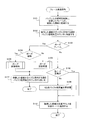
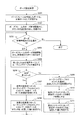
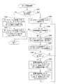
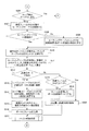
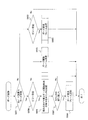
- FIG. 1 It is a figure which shows the example of the network to which the communication apparatus of 1st Embodiment is applied. It is a conceptual diagram explaining the alternative route search at the time of failure occurrence. It is a figure explaining the format of a frame. It is a flowchart of a frame reception process. It is a flowchart of a pose setting process. It is a figure explaining the example of the pause setting process in a 2nd operation example. It is a flowchart of a pause release process. It is a flowchart of the buffer usage amount addition processing by GD. It is a flowchart (the 1) of a reception data frame process. It is a flowchart (the 2) explaining a reception data frame process.
- each communication device The details of the operation of each communication device will be described with reference to FIGS. In the description of the operation of each communication device, the relationship between the operation of each communication device and the behavior of the entire network will be described with reference to FIGS. 1 to 13 as appropriate. Then, 2nd Embodiment and other embodiment are described.
- each communication device is an individual node in the network, and therefore the communication device is also referred to as a “node device” or “node”.
- a network including one or more communication devices is also referred to as a “node group”.
- the nodes may be part of a larger network.
- the first and second communication devices are referred to as “adjacent”. That is, the number of hops between two adjacent communication devices is one. In other words, when a wired or wireless link is established between the first and second communication devices, the first and second communication devices are adjacent to each other.
- the first and second communication devices when the first and second communication devices are directly connected by a cable and the first and second communication devices can communicate information via the cable, the first and second communication devices are connected. There is a wired link between the first and second communication devices, and the first and second communication devices are adjacent to each other.
- the first and second communication devices when the first and second communication devices can directly communicate information wirelessly without being relayed by the third communication device, the first and second communication devices are wirelessly connected between the first and second communication devices. A link exists and the first and second communication devices are adjacent to each other.
- links are not fixed and can change dynamically.
- a wireless link may be newly established or a wireless link that has been established may disappear due to the influence of weather, shielding, or the like. If the communication device is movable, the presence or absence of a link may change due to a change in the distance between the communication devices. Further, by changing the connection of the cable, a new wired link may be established, or the existing wired link may disappear, and the wired link may disappear due to a failure such as cable disconnection.
- the second communication device for the first communication device may be referred to as an “adjacent communication device”.
- the first communication device is an “adjacent communication device”. Note that “adjacent communication device” may be referred to as “adjacent node” in the same manner that “communication device” may be referred to as “node”.
- a PDU Protocol Data Unit
- a frame a unit of data transmitted and received between communication devices in accordance with a communication procedure (protocol) and unit data of transmission / reception itself.
- various frames are processed. Frames are classified from several viewpoints as follows.
- Frames can be classified according to whether or not they include an “ad hoc header” shown in FIG.
- a frame including an ad hoc header is referred to as an “ad hoc frame”.
- an example of a frame that does not include an ad hoc header is, for example, an Ethernet frame used in the well-known Ethernet (registered trademark).
- the ad hoc frame can be further classified into a data frame including an Ethernet frame following the ad hoc header and a control frame including another specific type of control data after the ad hoc header.
- a pause frame used in each of the following embodiments and an ACK (ACKnowledge) frame described later with respect to the second embodiment are specific examples of control frames.
- unicast frames in which only one communication device is designated as the final destination, and there are frames that are transmitted to a plurality of adjacent communication devices.
- frames may be other types of frames such as broadcast frames flooded in the network.
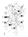
- FIGS. 1 to 3 are diagrams illustrating a first operation example of the pause control according to the first embodiment.
- FIGS. 4 and 5 illustrate a second operation example of the pause control according to the first embodiment. It is a figure explaining.
- pause control in a communication device is a control for requesting an adjacent communication device to pause transmission of a frame to the communication device, and notifies the adjacent communication device that frame transfer is resumed. Including control for.
- the network 1 shown in FIGS. 1 to 5 includes nodes 2 to 7 and node groups 8 to 13.
- the topology of the network 1 is as follows. Node 2 and node 3 are adjacent.
- Node 3 and node 4 are adjacent.
- Node 2 is adjacent to one or more nodes in the node group 8.
- the node 2 is adjacent to one or more nodes in the node group 9.
- the node 3 is adjacent to one or more nodes in the node group 10.
- the node 3 is adjacent to one or more nodes in the node group 11.
- the node 4 is adjacent to one or more nodes in the node group 9.
- the node 4 is adjacent to one or more nodes in the node group 12.
- the node 5 is adjacent to one or more nodes in the node group 9.
- the node 6 is adjacent to one or more nodes in the node group 9.
- the node 7 is adjacent to one or more nodes in the node group 9.
- a certain node in the node group 9 and a certain node in the node group 13 are adjacent to each other.
- a certain node in the node group 12 and a certain node in the node group 13 are adjacent to each other.
- the network 1 having the above topology may be used for the purpose of collecting information from other nodes in the nodes 5 to 7 with the nodes 5 to 7 as goal nodes, for example.
- a node in the node group 8 may transmit a frame with the node 5 as a final destination, and other nodes in the node group 8 may transmit a frame with the node 6 or the node 7 as a final destination. You may send it.
- a certain node in the node group 8 may transmit a frame with two or more goal nodes among the nodes 5 to 7 as final destinations according to the type of information to be transmitted. The same applies to each node (not shown) in the node groups 9 to 13.
- the communication device used as a node in the first embodiment controls a path for transmitting a frame for each final destination of the frame.
- the first transmission source communication device in the network 1 is referred to as “GS (Global Source)”
- the final destination communication device in the network 1 is referred to as “GD (Global Destination)”. That's it.
- this frame is relayed by the node 3.
- Node 3 controls the frame transmission path according to the GD of the frame. For example, the node 3 may transmit the frame to the adjacent node 4 if the GD of the frame is the node 5, and may transmit the frame to the adjacent node 2 if the GD of the frame is the node 6 or 7. .
- the node 3 that is not a GD may transmit the received frame to the node 2 or 4 that is an adjacent communication device in order to relay (that is, forward) the received frame.
- the communication device that is the transmission source of the frame is called “LS (Local Source)”
- the communication device that is the destination of the frame is “LD (Local Destination)”. That's it.
- the node 3 is LS and the node 4 is LD.
- the communication apparatus also performs pause control for each GD in response to controlling the transmission path for each GD.
- pause control By performing both transmission path control and pause control for each GD, it is possible to suppress the load bias of the network 1 as a whole, and to suppress the fluctuation of the load in each communication device. As a result, better load distribution is realized.
- 1 to 5 show specific examples of load distribution according to the first embodiment.
- the node 5 is designated as the GD, and the amount of frames received by the node 2 from one or a plurality of adjacent nodes in the node group 8 per unit time is 1 when an appropriate amount is a unit amount.
- the node 6 is designated as the GD, and the amount of frames received by the node 2 per unit time from one or a plurality of adjacent nodes in the node group 8 is 1 unit according to the unit amount.
- the node 7 is designated as the GD, and the amount of frames received by the node 2 per unit time from one or a plurality of adjacent nodes in the node group 8 is 1 unit according to the unit amount. To do.
- the amount of frames received per unit time will be represented by GD using the above unit amount and using a notation such as Equation (1).
- Equation (1) indicates the amount of frames received by the node 2 per unit time from one or a plurality of adjacent nodes in the node group 8 as described above, by GD.
- the expression (1) indicates the data amount D101 that the node 2 processes per unit time due to the node group 8.
- the amount of frames whose GD is node 5 is represented by the height of a white rectangle
- the amount of frames whose GD is node 6 is represented by the height of a black rectangle
- GD is node 7
- the amount of a certain frame is represented by the height of the rectangle of the oblique line pattern.
- Equation (2) corresponds to the data amount D102 in FIG. ⁇ Node 5, 1>, ⁇ Node 6, 1>, ⁇ Node 7, 1> ⁇ (2)
- Equation (3) corresponds to the data amount D103 in FIG. ⁇ Node 5, 1>, ⁇ Node 6, 1>, ⁇ Node 7, 1> ⁇ (3)
- Equation (4) corresponds to the data amount D104 in FIG. ⁇ Node 5, 2>, ⁇ Node 6, 2>, ⁇ Node 7, 2> ⁇ (4)
- the policy that the node 3 performs transmission path control (that is, frame routing) is as follows. That is, the node 3 selects the node 4 as the LD for the frame with the GD of the node 5, and selects the node 2 as the LD for the frame with the GD of the node 6 or 7.
- Equations (5) and (6) correspond to the data amounts D105 and D106 in FIG. 1, respectively.
- the node 2 controls the transmission path so that the frame is transmitted to the adjacent node in the node group 9 regardless of the GD of the received frame. Even if the following three nodes are three different nodes, two different nodes, or the same one node, the following discussion is not affected.
- a node in the node group 9 selected by the node 2 as the LD of the frame of the node 5 GD A node in the node group 9 selected by the node 2 as the LD of the frame of the node 6 GD is the frame of the node 7 Node in node group 9 selected by node 2 as LD
- the node 2 transmits the frame of the nodes 5 to 7 to the node group 9”. Then, since the node 2 transmits the frames of the nodes 5 to 7 to the node group 9, the node 2 transmits to the one or more adjacent nodes in the node group 9 from the expressions (1) and (5).
- the amount of the frame is expressed as Equation (7). Expression (7) corresponds to the data amount D107 in FIG. ⁇ Node 5, 1>, ⁇ Node 6, 3>, ⁇ Node 7, 3> ⁇ (7)
- Equation (8) corresponds to the data amount D108 in FIG. ⁇ Nodes 5, 4>, ⁇ Node 6, 2>, ⁇ Node 7, 2> ⁇ (8)
- FIG. 2 is a diagram showing the network 1 at time T2 when the node 4 is in a busy state as described above.
- the data amount D201 transmitted from the node group 8 to the node 2 is the same as the data amount D101 of FIG. 1, and is represented by Expression (1).
- the data amount D202 transmitted from the node group 10 to the node 3 is the same as the data amount D102 of FIG. 1 and is expressed by the equation (2).
- the data amount D204 transmitted from the node group 12 to the node 4 is the same as the data amount D104 in FIG. 1 and is expressed by the equation (4).
- Equation (12) corresponds to the data amount D203 in FIG. Further, as is clear from the comparison with the equation (3) corresponding to the data amount D103 in FIG.
- the node 3 selects the node 2 as the LD for the frame whose GD is the node 6 or 7. That is, the amount of frames transmitted by the node 3 to the node 2 is not affected even when the amount of frames of the node 5 increases by the GD, and is expressed by the equation (5) similarly to the data amount D105 of FIG.
- the data amounts D201 and D205 are the same as the data amounts D101 and D105 in FIG. 1, the amount of frames transmitted from the node 2 to the node group 9 is also the same as in FIG. That is, the data amount D207 in FIG. 2 is expressed by the equation (7), similarly to the data amount D107 in FIG.
- the node 3 selects the node 4 as the LD for the frame in which the GD is the node 5. Therefore, the amount of frames transmitted from the node 3 to the node 4 is increased as compared with the equation (6) corresponding to the data amount D106 in FIG. 1, and specifically, as the equation (13). Expression (13) corresponds to the data amount D206 of FIG.
- the node 4 requests the adjacent node to pause the transmission of the frame to the node 4, thereby reducing the load and eventually recovering from the busy state.
- the frame transmission pause request is realized by transmitting a pause request frame.
- the pause request frame is information indicating that the type of the frame is a pause request frame, and pauses transmission of a frame with which node is a GD. Contains information specifying what to request. As will be described in detail later, the number of GDs specified in the pause request frame may be one or plural.
- the node 4 transmits a pause request frame P1 for requesting to pause transmission of a frame having the node 7 as a GD to the node 4 to each adjacent node.
- a pause request frame P1 for requesting to pause transmission of a frame having the node 7 as a GD to the node 4 to each adjacent node.
- the process for determining the GD specified in the pause request frame varies depending on the embodiment, as will be described in detail with reference to FIGS.
- the node 4 determines that “the node 7 is appropriate as the GD specified by the pause request frame P1” according to some criteria.
- FIG. 3 shows the state of the network 1 at time T3 when a little time has elapsed since the transmission of the pause request frame P1. Since only the node adjacent to the node 4 receives the pause request frame P1, the node groups 8, 10, 11, etc. not adjacent to the node 4 are not directly affected by the pause request frame P1.
- the data amount D301 transmitted from the node group 8 to the node 2 is the same as the data amount D201 of FIG. 2, and is represented by the equation (1).
- the data amount D302 transmitted from the node group 10 to the node 3 is the same as the data amount D202 of FIG. 2, and is expressed by the equation (2).
- the data amount D303 transmitted from the node group 11 to the node 3 is the same as the data amount D203 in FIG. 2 and is expressed by the equation (12).
- Equation (17) represents the data amount D304 of FIG. ⁇ Node 5, 2>, ⁇ Node 6, 2> ⁇ (17)
- Equation (18) represents the data amount D309 in FIG. ⁇ Node 7, 2> ⁇ (18)
- the frame transmitted from the node 3 to the node 4 is only a frame having the node 5 as a GD. That is, the data amount D306 transmitted from the node 3 to the node 4 is not affected by the pause request frame P1, and therefore is not changed from the data amount D206 of FIG. 2 and is expressed by the equation (13).
- the data amount D305 transmitted from the node 3 to the node 2 is not changed from the data amount D205 of FIG. 2 and is expressed by the equation (5). Therefore, the data amount D307 transmitted from the node 3 to the node group 9 is also the same as the data amount D207 in FIG.
- the data amounts D304 and D306 flowing into the node 4 are expressed by equations (17) and (13), respectively. Further, as described above, the node 4 transmits the frame to the adjacent node in the node group 9 regardless of which of the nodes 5 to 7 the GD of the received frame is. Therefore, the data amount processed by the node 4 is the data amount D308 transmitted from the node 4 to the node group 9. Further, from the equations (17) and (13), the data amount D308 is expressed by the following equation (19). ⁇ Node 5, 7>, ⁇ Node 6, 2> ⁇ (19)
- the frame of the data amount D309 transmitted from the node group 12 to the node group 13 and having the node 7 as GD is transmitted from the node group 13 to the node group 9.
- the data amount D310 in FIG. 3 indicates the amount of frames transmitted from the node group 13 to the node group 9 in this way, and is expressed by the above equation (18) as with the data amount D309.
- the node 4 since 9 ⁇ 10, the node 4 recovers from the busy state of FIG. Therefore, the node 4 notifies the adjacent node of the recovery from the busy state. That is, the node 4 notifies the adjacent node that transfer of a frame with the node 7 as a GD is resumed. In other words, the node 4 issues a notification for permitting an adjacent node to transmit a frame having the node 7 as a GD to the node 4.
- the above notification is realized by transmitting a pause release frame.
- An example of a specific format of the pause release frame will be described later with reference to FIG. 13.
- the pause release frame resumes transfer of information indicating that the frame type is a pause release frame and a frame whose node is a GD. Contains information that explicitly or implicitly specifies As will be described in detail later, when GD is explicitly designated in the pause release frame, the number of designated GDs may be one or plural.
- the node 4 recovered from the busy state transmits a pause release frame R1 in which the same node 7 designated in the pause request frame P1 is designated as the GD to be paused to each adjacent node.
- notification by a pause release frame is not always necessary, but it is useful for effective use of network resources.
- the transmission path is not changed due to the pause release frame R1 for the following three reasons.
- the first reason is that the node 3 that has received the pause release frame R1 originally controls the transmission path so as to transmit a frame having the node 7 as GD to the node 2 instead of the node 4. Therefore, transmission from the node 3 to the node 4 is not affected by the pause release frame R1.
- the second reason is that one or more nodes adjacent to node 4 in node group 12 have changed the transmission path control policy so that a frame with node 7 as GD is transmitted to node group 13 instead of node 4 That's why.
- the third reason is that, in the example of FIG. 3, there is a path that can transmit a frame without failure from the node group 12 to the node 7 via the node group 13 and the node group 9. .
- one or more nodes in the node group 12 that have transmitted the frame with the node 7 as GD to the node 4 at the time T2 in FIG. 2 again after the time T3. There is no need to change the transmission path control policy. Therefore, one or more nodes adjacent to the node 4 in the node group 12 continue to use the transmission path changed in response to the reception of the pause request frame P1 after the time T3.
- the node 4 may determine that “the node 5 is appropriate as the GD specified by the pause request frame” at the time T2. 4 and 5 show examples when the node 4 makes such a determination.
- the node 4 transmits a pause request frame designating the node 5 as GD
- the node groups 8, 10, and 11 not adjacent to the node 4 are not directly affected by the pause request frame. Therefore, in FIG. 4, the data amount D401 transmitted from the node group 8 to the node 2 is the same as the data amount D201 of FIG. 2, and is represented by the equation (1).
- the data amount D402 transmitted from the node group 10 to the node 3 is the same as the data amount D202 of FIG. 2, and is expressed by the equation (2).
- the data amount D403 transmitted from the node group 11 to the node 3 is the same as the data amount D203 in FIG. 2 and is expressed by Expression (12).
- the transmission of a frame having the node 5 as GD to the node 4 is suspended. That is, one or more nodes adjacent to the node 4 in the node group 12 transmit a frame having the node 5 as a GD to a route different from the node 4 (specifically, a node in the node group 13).
- Equation (21) represents the data amount D404 in FIG. ⁇ Node 6, 2>, ⁇ Node 7, 2> ⁇ (21)
- the node 3 that has received the pause request frame (not shown) transmits a frame having the node 5 as a GD to a route different from that of the node 4. Specifically, the node 3 transmits not only a frame having the node 6 or 7 as a GD but also a frame having the node 5 as a GD to the node 2.
- Expression (22) the amount of frames transmitted from the node 3 to the node 2 is expressed by Expression (22) when expressed by GD. Equation (22) represents the data amount D405 of FIG. ⁇ Nodes 5, 5>, ⁇ Node 6, 2>, ⁇ Node 7, 2> ⁇ (22)
- the data amounts D401 and D405 flowing into the node 2 are expressed by equations (1) and (22), respectively. Further, as described above, the node 2 transmits the frame to the adjacent node in the node group 9 regardless of which of the nodes 5 to 7 is the GD of the received frame. Therefore, the data amount processed by the node 2 is the data amount D407 transmitted from the node 2 to the node group 9, and the data amount D407 is expressed by the equation (23) from the equations (1) and (22). Is done. ⁇ Nodes 5, 6>, ⁇ Node 6, 3>, ⁇ Node 7, 3> ⁇ (23)
- node 2 falls into a busy state.
- the busy state propagates from the node 4 to the node 2 because the node 4 that has fallen into the busy state at time T2 transmits a pause request frame (not shown) that designates the node 5 as the GD. .
- the node 2 selects the node 6 according to some criteria, and transmits a pause request frame P3 requesting to pause transmission of the frame having the node 6 as a GD to the node 2 to the adjacent node.
- the node 3 that has transmitted the frame with the node 5 as GD to the node 4 until time T2 receives the pause request frame (not shown) from the node 4 the frame with the node 5 as GD is received as described above. It is not transmitted to the node 4. Therefore, the amount of frames flowing into the node 4 (in other words, the amount of frames processed by the node 4) is equal to the data amount D404.
- the node 4 transmits the frame to the adjacent node in the node group 9 regardless of which of the nodes 5 to 7 is the GD of the received frame. Therefore, the data amount D408 transmitted from the node 4 to the node group 9 is also equal to the data amount D404 and is expressed by the equation (21).
- node 4 since 4 ⁇ 10, node 4 recovers from the busy state. Then, as shown in FIG. 4, the node 4 transmits a pause release frame R ⁇ b> 2 for notifying the adjacent node that the transfer of the frame having the node 5 as the GD is resumed.
- Equation (26) represents the data amount D409 of FIG. ⁇ Node 5, 2> ⁇ (26)
- the frame of the data amount D409 transmitted from the node group 12 to the node group 13 and having the node 5 as GD is transmitted from the node group 13 to the node group 9.
- the data amount D410 in FIG. 4 indicates the amount of frames transmitted from the node group 13 to the node group 9 in this way, and is also expressed by Expression (26).
- the network 1 including the communication device according to the first embodiment as individual nodes autonomously transitions to a state in which the load is less biased, even with some trial and error.
- Equation (27) represents the data amount D501 in FIG. ⁇ Node 5, 1>, ⁇ Node 7, 1> ⁇ (27)
- one or more nodes adjacent to the node 2 transmit a frame in which the GD is the node 6 through a route different from that of the node 2.
- the example of FIG. 5 is an example in which a frame with a GD of node 6 is transmitted from the node group 8 to the node group 9.
- the amount of frames transmitted from the node group 8 to the node group 9 in this way is expressed by equation (28) by GD, and equation (28) represents the data amount D511 in FIG. ⁇ Node 6, 1> ⁇ (28)
- Equation (29) represents the data amount D505 in FIG. ⁇ Nodes 5, 5>, ⁇ Node 7, 2> ⁇ (29)
- the node 3 transmits a frame having the node 6 as a GD to a route different from that of the node 2 when the pause request frame P3 is received. Specifically, the node 3 transmits a frame having the node 6 as a GD to the node 4.
- the amount of frames transmitted from the node 3 to the node 4 is expressed by Expression (30) when expressed by GD. Equation (30) represents the data amount D506 in FIG. ⁇ Node 6, 2> ⁇ (30)
- the node groups 10 to 13 not adjacent to the node 2 are not directly influenced by the pause request frame P3. Therefore, the data amount D502 transmitted from the node group 10 to the node 3 is the same as the data amount D402 in FIG. 4 and is expressed by the equation (2). Further, the data amount D503 transmitted from the node group 11 to the node 3 is the same as the data amount D203 of FIG. 2 and is expressed by the equation (12).
- the data amount D504 transmitted from the node group 12 to the node 4 is the same as the data amount D404 in FIG. 4 and is expressed by the equation (21). Further, the data amount D509 transmitted from the node group 12 to the node group 13 is the same as the data amount D409 in FIG. 4 and is expressed by Expression (26). Similarly, the data amount D510 transmitted from the node group 13 to the node group 9 is the same as the data amount D410 of FIG. 4 and is expressed by the equation (26) as with the data amount D509.
- the node 3 and the nodes in the node group 8 change the path control policy as described above when the pause request frame P3 is received, as a result, the data amount processed by the node 2 is the inflowing data amount D501. And D505. Further, as described above, the node 2 transmits the frame to the adjacent node in the node group 9 regardless of which of the nodes 5 to 7 is the GD of the received frame.
- the data amount D507 transmitted from the node 2 to the node group 9 at time T5 shown in FIG. 5 is expressed by the following equation (31) from the equation (27) indicating the data amount D501 and the equation (29) indicating the data amount D505. ).
- equation (31) the data amount D507 transmitted from the node 2 to the node group 9 at time T5 shown in FIG. 5 is expressed by the following equation (31) from the equation (27) indicating the data amount D501 and the equation (29) indicating the data amount D505. ).
- node 2 recovers from the busy state. Therefore, the node 2 notifies the adjacent node of the recovery from the busy state. That is, the node 2 transmits a pause release frame R3 in which the same node 6 designated in the pause request frame P3 in FIG. 4 is designated as a pause release target GD to each adjacent node.
- the transmission path change caused by the pause release frame R3 does not occur for the same reason as described as the reason why the transmission path change caused by the pause release frame R1 does not occur.
- the processing load at the time T5 of the node 4 recovered from the busy state at the time T4 is equal to the sum of the inflowing data amounts D504 and D506.
- the node 4 transmits the frame to the adjacent node in the node group 9 regardless of which of the nodes 5 to 7 is the GD of the received frame.
- the data amount D508 transmitted from the node 4 to the node group 9 is expressed by the equation (33) from the equations (21) and (30). ⁇ Node 6, 4>, ⁇ Node 7, 2> ⁇ (33)
- each node in the network 1 performs pause control using the pause request frame and pause release frame, thereby realizing appropriate load distribution for the network 1 as a whole.
- an approach different from the approach of “a node that has fallen into a busy state or its adjacent node tries to recover from the busy state by discarding the frame” is used. It has been taken.
- the adjacent node of the node that has fallen into the busy state switches the transmission path of the frame, thereby reducing the load on the node that has fallen into the busy state and discarding the frame that has been transferred halfway. Realize both prevention. Therefore, according to the first embodiment, data relay can be continued while avoiding congestion.
- the pause control for each GD as in the first embodiment is useful for averaging the load in the entire network 1, in other words, it is useful for effective use of resources.
- a comparative example in which information specifying the GD is not included in the pause request frame and the pause release frame will be described next.
- the node 4 transmits a pause request frame not including information specifying the GD at time T2 in FIG. Then, each node adjacent to the node 4 pauses transmission of the frame to the node 4 regardless of the GD of the frame.
- the node 3 transmits the frame of the data amount D206 that has been transmitted to the node 4 until now to the node 2, for example, when the pause request frame is received from the node 4. . Further, the node adjacent to the node 4 in the node group 12 also receives the frame of the data amount D204 that has been transmitted to the node 4 until the reception of the pause request frame from the node 4, for example, in the node group 13 It will be sent to the node.
- the data amount of the frame transmitted from the node 3 to the node 2 is the sum of the data amounts D205 and D206 in FIG. ⁇ Nodes 5, 5>, ⁇ Node 6, 2>, ⁇ Node 7, 2> ⁇ (35)
- this pause request frame also does not include information specifying GD.
- each node adjacent to the node 2 pauses transmission of the frame to the node 2 regardless of the GD of the frame.
- a node adjacent to the node 2 in the node group 8 transmits a frame of the data amount D201 to the path between the node groups 8 and 9 shown in FIG. 5 when receiving the pause request frame from the node 2. To come.
- the pause request frame is transmitted from the node 2, the frame is not transmitted to the node 2, so that the busy state is eventually canceled in the node 2, and the processing load becomes zero.
- the pause request frame does not include information specifying the GD
- the data amount of the frame transmitted between adjacent nodes varies drastically with the pause request frame as a trigger.
- the processing load of the node 4 varies from the data amount D208 in FIG. 2 (that is, 11 in total) to 0. Further, the processing load of the node 2 also varies from 12 in the equation (36) to 0.
- the amount of data of a frame transmitted from a certain node to an adjacent node becomes 0 at a stroke triggered by the pause request frame. ⁇ Changes to the nothing type. And if the fluctuation
- the amount of data of a frame transmitted from a certain node to an adjacent node is always reduced to zero, although the amount of data decreases with the pause request frame as a trigger. It doesn't mean that Therefore, compared with the comparative example, in the first embodiment, the fluctuation in the data amount of the frame transmitted between adjacent nodes is triggered more slowly when the pause request frame is transmitted. Therefore, the first embodiment is useful for averaging the load in the entire network 1, in other words, effective for effective use of resources.
- congestion is avoided by pause control using a pause request frame and a pause release frame.
- it is possible to prevent data from being discarded while avoiding congestion (that is, to continue relaying data while avoiding congestion).
- FIG. 6 is a functional configuration diagram of the communication device.
- the communication apparatus 100 in FIG. 6 includes a table storage unit 101 that stores various tables, and a buffer 102 that stores frames.
- the communication apparatus 100 includes a reception unit 103, a reception frame control unit 104, an upper layer processing unit 105, a table control unit 106, a port monitoring unit 107, a port selection unit 108, a timer 109, a transmission frame control unit 110, and a transmission unit. 111.
- the port selection unit 108 includes a pause control unit 112.
- the communication device 100 further includes a busy detection unit 113 and a buffer usage total counter 114.
- the table storage unit 101 stores a routing table 121, a loop detection table 122, a port link state table 123, a MAC table 124, a pause state management table 125, a buffer in use GD table 126, and a pause history table 127.
- the table storage unit 101 may be realized by, for example, a DRAM (Dynamic Random Access Memory) or a CAM (Content-Addressable Memory) and an SRAM (Static Random Access Memory). Details of each table will be described later with reference to FIGS.
- Buffer 102 is used to store frames.
- the buffer 102 is, for example, a DRAM.
- the total usage amount of the buffer 102 is recorded in the buffer usage total amount counter 114.
- the communication device 100 has a storage device (not shown) in addition to the table storage unit 101 and the buffer 102.
- the communication device 100 has a nonvolatile storage device such as a flash memory, and the nonvolatile storage device stores the node ID of the node device 100 itself, the MAC address of the node device 100 itself, and the like.
- the communication device 100 includes an MPU (MicroProcessing Unit)
- MPU MicroProcessing Unit
- the DRAM is used not only as the buffer 102 but also as a working area when the MPU executes a program.
- the receiving unit 103 receives the frame, stores the received frame in the buffer 102, and increases the count value of the total buffer usage counter 114 according to the size of the received frame.
- the hardware that implements the receiving unit 103 includes, for example, a plurality of physical ports and a physical layer processing chip (PHY chip).
- the reception frame control unit 104 classifies the frames received by the reception unit 103 and stored in the buffer 102 according to information such as type and destination. That is, the reception frame control unit 104 reads information such as type and destination from the buffer 102, and performs control according to the read information.
- the received frame control unit 104 requests the upper layer processing unit 105 to process the payload of the frame.
- the reception unit 103 controls the routing table 121 according to the designated contents. This affects the policy regarding the routing of data frames received later.
- the upper layer processing unit 105 processes a frame that designates the communication device 100 itself as a GD.
- the “upper layer” means a layer higher than the layer in which the ad hoc frame is defined, and is a layer corresponding to the payload of the ad hoc frame.
- the upper layer processing unit 105 also creates a payload of a frame that the communication device 100 itself transmits as a GS.
- the upper layer processing unit 105 reads and processes the payload of the frame transmitted to the communication device 100 and stored in the buffer 102, or creates the payload of the frame transmitted from the communication device 100 on the buffer 102. Or The higher layer processing unit 105 increases the counter value of the total buffer usage counter 114 when data is created on the buffer 102, and decreases the counter value of the total buffer usage counter 114 when data is deleted from the buffer 102.
- the table control unit 106 controls the contents of various tables by creating / updating / deleting entries of the various tables stored in the table storage unit 101. For example, when a CAM and an SRAM are used to realize the table storage unit 101, the table control unit 106 may perform a CAM search and access to an SRAM address obtained as a search result. The table control unit 106 controls the contents of various tables according to control information provided from the reception frame control unit 104, the port monitoring unit 107, the port selection unit 108, the timer 109, and the transmission frame control unit 110.
- the port monitoring unit 107 monitors the state of each of the plurality of ports included in the communication device 100. Then, the port monitoring unit 107 writes the monitoring result in the pause state management table 125 via the table control unit 106.
- the hardware for realizing the reception unit 103 and the transmission unit 111 may be common hardware, and the reception unit 103 and the transmission unit 111 include a plurality of physical ports and a PHY chip connected to each physical port.
- the port and the PHY chip may be 1: 1 compatible or N: 1 compatible.
- the PHY chip connected to the physical port may detect whether or not the link connected to each physical port is down, and the port monitoring unit 107 detects the detection result output from the PHY chip.
- the port status may be monitored by reading.
- the port selection unit 108 refers to the table stored in the table storage unit 101 and selects a frame transmission destination port. The selection is made according to the header information of the frame output from the reception frame control unit 104.
- the port selection unit 108 may refer to the table via the table control unit 106 or may directly refer to the table.
- the timer 109 notifies the table control unit 106 of time information used for aging entries in various tables.
- entries in various tables may include a field indicating a valid period.
- the field indicating the valid period is not shown in FIGS.
- the transmission frame control unit 110 performs various controls related to frame transmission. For example, the transmission frame control unit 110 generates or rewrites the header of the frame in which the payload is stored in the buffer 102. Specifically, the transmission frame control unit 110 performs control for transmitting a frame from the transmission port selected by the port selection unit 108.
- the transmission unit 111 reads the frame from the buffer 102 and transmits the frame to the port designated by the transmission frame control unit 110. In addition, the transmission unit 111 decreases the count value of the buffer usage total amount counter 114 according to the size of the frame to be transmitted.
- the hardware that implements the transmission unit 111 may be common to the reception unit 103, and includes, for example, a plurality of physical ports and a PHY chip.
- the pause control unit 112 is included in the port selection unit 108.
- the pause control unit 112 controls transmission of a pause request frame and a pause release frame.
- the busy detection unit 113 refers to the counter value of the buffer usage total amount counter 114 to determine whether or not the communication device 100 is in a busy state. For example, when the counter value is equal to or greater than a predetermined threshold, the busy detection unit 113 may determine that “the communication device 100 is in a busy state”. When the communication device 100 includes an MPU, the busy detection unit 113 may further determine whether the communication device 100 is in a busy state by referring to the usage rate or usage time of the MPU. The busy detection unit 113 notifies the pause control unit 112 of the determination result.
- the total buffer usage counter 114 is a counter indicating the total usage of the buffer 102.
- the receiving unit 103 and the upper layer processing unit 105 increase the counter value of the total buffer usage counter 114 according to the size of the frame.
- the transmission unit 111 and the upper layer processing unit 105 read the frame data from the buffer 102 and release the area in which the data is stored, the transmission unit 111 and the upper layer processing unit 105 decrease the counter value of the total buffer usage counter 114 according to the frame size. .
- Hardware for realizing the reception frame control unit 104, the upper layer processing unit 105, the table control unit 106, the port monitoring unit 107, the port selection unit 108, the timer 109, the transmission frame control unit 110, the pause control unit 112, and the busy detection unit 113 The wear is optional depending on the embodiment.
- these units may be realized by an FPGA (Field Programmable Gate Array), an MPU, or an ASIC (Application Specific Integrated Circuit).
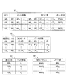
- FIG. 7 is a diagram (part 1) illustrating an example of a table stored in the table storage unit 101.
- the routing table 121 in FIG. 7 has entries that associate the following information with each other. "Destination” which is the GD of the frame X “port states” indicating the states of the x ports included in the communication device 100 "Counter” for each of x ports “Pause GD” indicating whether or not the communication device 100 itself pauses the transfer of the frame addressed to the GD indicated by the “destination”.
- FIG. 7 illustrates a routing table 121 including n entries. As will be described later, each entry is added to the routing table 121 based on a frame received by the communication apparatus 100. Each entry is deleted from the routing table 121 when it is not accessed for a predetermined time.
- the states RP 1i to RP xi of the x ports are associated with the destination GD i .
- the port of the communication apparatus 100 according to the present embodiment will be described as having a transmission / reception function.
- the destination GD i is identification information for identifying a communication device serving as a frame destination in a wired ad hoc network including a plurality of communication devices similar to the communication device 100.
- a 3-byte ID (IDentification) that is unique within a wired ad hoc network is assigned in advance to each communication device.
- an ID assigned to the communication device is referred to as a “node ID”.
- the destination GD i is specifically a node ID.
- the destination GD i may be other information for identifying the communication device, such as a MAC address.
- the port selection unit 108 refers to the routing table 121 and sets the transmission port. decide.
- the state RP ji of the j-th (1 ⁇ j ⁇ x) port is “U” (Used), “E” (Empty), “L” (Loop), “P”. ”(Pause) and“ D ”(Down).
- “U” indicates a use state. Specifically, the j-th port is actually used as a transmission destination port in the communication apparatus 100 for transmitting a frame to another communication apparatus identified by the node ID of the destination GD i .
- the port state RP ji is “U”. That is, the “U” state is an example of a state indicating “transmittable”.
- E indicates an unused state. Specifically, the j-th port has never been used as a transmission destination port in the communication apparatus 100 for transmitting a frame to another communication apparatus identified by the node ID of the destination GD i.
- the port state RP ji is “E”. That is, the “E” state is an example of a state indicating “transmittable”.
- “L” indicates a loop state. Specifically, when the following two conditions are both satisfied, the state RP ji is updated to “L”.
- the j-th port has been used once as a transmission destination port in the communication apparatus 100 for transmitting a frame to another communication apparatus identified by the node ID of the destination GD i .
- a frame transmitted from the j-th port to another communication device identified by the node ID of the destination GD i loops in the network and returns to the communication device 100 itself (that is, received again by the communication device 100) Was).
- port state RP ji is "because when transmitting a frame to the destination GD i from the port j-th port results in loops, frames port j-th to the destination GD i Should not be sent from any other port. " That is, the “L” state is an example of a state indicating “transmission impossible”.
- P indicates a pause state. Specifically, when a “pause request” is received from the j-th port (that is, from an adjacent node device (not shown) connected via the j-th port), the port state RP ji is “P”. It becomes.
- the “pause request” is a request that a node device whose processing load has increased due to frame concentration or the like “pauses” transmission of a frame to its own node device for a certain period of time from an adjacent node device. It is a request. More specifically, the pause request is transmitted as the pause request frame described with reference to FIGS.
- the communication apparatus 100 When receiving a pause request frame at the jth port, the communication apparatus 100 recognizes that the adjacent node connected to the jth port is busy.
- GD is designated in the pause request frame.
- a value indicating the length of time hereinafter referred to as “counter” is also specified in the pause request frame.
- the communication apparatus 100 that has received the pause request frame at the j-th port transmits a pause request frame to a node addressed as a GD in the pause request frame during the period specified by the counter. It is not transmitted to the adjacent node device. That is, the pause control unit 112 of the communication apparatus 100 recognizes that “a frame addressed to a node designated as GD in the pause request frame should not be transmitted to the adjacent node apparatus that has transmitted the pause request frame”.
- the reception frame control unit 104 sets the state RP ji corresponding to the j-th port in the routing table 121 to “P”.
- the “P” state is an example of a state indicating “transmission impossible”.
- “D” indicates a link-down state. For example, if the signal carried on the cable cannot be electrically detected at the jth port, such as when the cable connected to the jth port is physically disconnected, the state RP ji is “D " The “D” state is also an example of a state indicating “transmission impossible”.
- the “D” state is a concept independent of the frame destination.
- some of the states RP j1 to RP jn of a certain port may be “D” and some may be other than “D”. This is because, in the first embodiment, as will be described later, the update of the entry in the routing table 121 is performed in response to the frame reception, so there is a time difference in the update timing of each entry.
- FIG. 8 is a port state state transition diagram in the routing table 121.
- the port state of the routing table 121 includes “E (Empty)” state, “U (Used)” state, “P (Pause)” state, “L (Loop)” state, and “D (Down)”. There is a state.
- the initial state of the port state is the “E” state.
- the “E” state and the “U” state surrounded by a thick line indicate that the port corresponding to this port state can be used as a transmission destination.
- the other “P” state, “L” state, and “D” state indicate that the port corresponding to this port state cannot be used as a transmission destination.
- the port state transitions from the “E” state to the “P” state (see step S105 in FIG. 14 described later). Note that the port state may transition to the “P” state from the other “U” state, “L” state, and “D” state upon receipt of the pause request frame (step of FIG. 14 described later). (See S105).
- the port state transitions from the “P” state to the “E” state in response to the reception (see step S106 in FIG. 14 described later). Further, even when the time specified in the pause request frame has elapsed, the port state transitions from the “P” state to the “E” state (see step S1806 in FIG. 35 described later).
- the port state of a port having an entry corresponding to a certain GD is in the “E” state, and this port is selected as the LD for this GD. Then, with the selection as a trigger, the port state transitions from the “E” state to the “U” state (see step S513 in FIG. 20, step S529 in FIG. 21, and step S714 in FIG. 24 described later).
- “D” can be obtained from any of the “E” state, “U” state, “P” state, and “L” state. There is a possibility of transition to a state (see step S510 in FIG. 20, step S525 in FIG. 21, and step S711 in FIG. 24 described later). On the contrary, when frame routing occurs after a certain port recovers from the link-down state, the “D” state transitions to the “E” state (step S510 in FIG. 20 described later, step S525 in FIG. 21). (See step S711 in FIG. 24).
- the counter CT ji is a value set by the reception frame control unit 104 when the reception unit 103 receives the pause request frame specifying the destination GD i at the j-th port. Specifically, the value of the counter included in the pause request frame is copied to the counter CT ji of the routing table 121.
- the counter CT ji is periodically counted down.
- the communication apparatus 100 considers that the adjacent node that has transmitted the pause request frame has recovered from the busy state. Specifically, when the counter CT ji becomes 0, the table control unit 106 resets the corresponding port state RP ji to the normal state (ie, “E” state).
- the pause GD ⁇ PGD i corresponding to the destination GD i in the routing table 121, the communication device 100 itself to the adjacent node is "1" when transmitting the pause request frame to the specified destination GD i. “1” indicates “selected”.
- the pause GD ⁇ PGD i When the communication apparatus 100 has not transmitted a pause request frame specifying the destination GD i , the pause GD ⁇ PGD i is “0”. “0” indicates “not selected”. When the communication apparatus 100 transmits a pause request frame specifying the destination GD i and then recovers from the busy state, the pause GD ⁇ PGD i returns from “1” to “0”.
- the table control unit 106 and the timer 109 cooperate to periodically perform an aging process on the routing table 121. Specifically, the table control unit 106 deletes an old entry that has passed a predetermined time from the latest time point out of the following three time points from the routing table 121. -When the entry was created-When the entry was last updated-When the entry was found to meet the search criteria
- loop detection table 122 of FIG. 7 includes “OLS (Original Local Source) port” and x “port states” indicating the state of each port in a set of “source” and “FID (Frame IDentification)”. Are stored in association with each other.
- FIG. 7 illustrates a loop detection table 122 including m entries. As will be described later, each entry is added to the loop detection table 122 based on the frame received by the communication apparatus 100. Each entry is deleted from the loop detection table 122 when a predetermined time elapses.
- the OLS port OLSP i and the port states LP 1i to LP xi of each port correspond to the pair of the transmission source GS i and FID i. It is attached.
- the transmission source GS i is identification information for identifying a communication device that is a frame transmission source in a wired ad hoc network including a plurality of communication devices similar to the communication device 100, and is specifically a node ID.
- FID i is identification information that uniquely identifies a frame, which is assigned to a frame to be transmitted by a transmission source communication device (that is, a communication device with a node ID of GS i ).
- FID i may be a sequence number, for example.
- the port selection unit 108 refers to not only the routing table 121 but also the loop detection table 122. Then, the port selection unit 108 selects a port to transmit the received frame based also on the loop detection table 122.
- the OLS port OLSP i in the i-th entry of the loop detection table 122 indicates a port that has received the frame when the communication apparatus 100 receives the frame that triggers the creation of the i-th entry.
- the frame assigned the FID i of FID i in the source communication device (that is, the communication device identified by the node ID GS i ) is the r-th port (1 ⁇ r ⁇ x) of the communication device 100.
- r is registered as the OLS port OLSP i .
- the port state LP ri of the r-th port is set to the “O (Original Local Source)” state.
- the OLS port OLSP i indicates which of the x port states LP ji is in the “O” state.
- the OLS port field is provided in the loop detection table 122 in order to save time for searching which port is in the “O” state, but the OLS port field may not be provided.
- the port state LP ji of the loop detection table 122 further includes an “E (Empty)” state, a “U (Used)” state, and an “L (Loop)” state.
- the “U” state indicates the usage state as described with respect to the routing table 121.
- the state LP ji is “U” when the following two conditions are satisfied.
- the communication apparatus 100 has once transmitted a frame to which the FID i of FID i is assigned in the transmission source communication apparatus identified by the node ID of the transmission source GS i . In the transmission, the j-th port is used as a transmission destination port in the communication apparatus 100.
- the “E” state indicates an unused state as described with respect to the routing table 121, and specifically has the following meaning in the loop detection table 122. That is, when the communication apparatus 100 once transmits a frame assigned the FID i of FID i in the transmission source communication apparatus identified by the node ID of the transmission source GS i , the transmission destination port is not the j-th port, and If j ⁇ r, the state LP ji is “E”.
- the “L” state indicates a loop state in the same manner as described with respect to the routing table 121. Specifically, in the loop detection table 122, the state LP ji becomes “L” when the following two conditions are satisfied.
- the communication device 100 may have transmitted a frame to which the FID i of FID i is assigned in the transmission source communication device identified by the node ID of the transmission source GS i using the jth port as the transmission destination port. The frame is received by the communication device 100 after transmission.
- the “U” state and the “E” state are common in the sense of “sendable”, that is, “selectable as a destination port”.
- the “U” state and the “E” state are distinguished as follows. That is, the “U” state in the loop detection table 122 indicates an object to be changed to the “L” state meaning “transmission impossible” if a loop is detected in the future.
- the “E” state in the loop detection table 122 indicates that even if a loop is detected in the future, it can still be selected as a destination port at the time of the transmission.
- the table control unit 106 and the timer 109 cooperate to periodically perform an aging process on the loop detection table 122. Specifically, the table control unit 106 deletes an old entry for which a predetermined time or more has passed since creation from the routing table 121.
- FIG. 9 is a port state state transition diagram in the loop detection table.
- the port state of the loop detection table 122 includes an “E (Empty)” state, a “U (Used)” state, an “L (Loop)” state, and an “O (Original Local Source)” state.
- the initial state varies depending on the port (see step S514 in FIG. 20 and step S715 in FIG. 24 described later). That is, in an entry identified by a certain GS and FID pair, the port state of the port that first received the frame having this FID transmitted from this GS is set to the “O” state. Further, when a frame having this FID transmitted from the GS is first received, the port state of the port selected as the transmission destination is set to the “U” state. The other ports are set to the “E” state.
- the port link state table 123 of FIG. 7 has x entries corresponding to each of the x ports. For example, in the entry corresponding to the i-th (1 ⁇ i ⁇ x) port, whether the port ID / PID i for identifying the i-th port and the link connected to the i-th port are communicable A link state L i indicating such is associated.
- the link state L i is binary, it can be represented by 1 bit.
- the port link state table 123 is periodically updated as follows. That is, the port monitoring unit 107 pays attention to the i-th (1 ⁇ i ⁇ x) port and determines whether or not the i-th port is in a connected state. For example, the port monitoring unit 107 determines based on the output of the PHY chip indicating whether the cable connected to the i-th port is in a communicable state or a link-down state.
- the port monitoring unit 107 performs table control. through the section 106 sets i-th port in the link state L i "C" state.
- the port monitor 107 via the table control unit 106 sets i-th port in the link state L i to "D" state .
- the port monitoring unit 107 performs the above processing for each i (1 ⁇ i ⁇ x). Thereby, the port link state table 123 is periodically updated.
- FIG. 7 illustrates a MAC table 124 having b entries.
- the i-th (1 ⁇ i ⁇ b) entry of the MAC table 124 is associated with the following two pieces of information.
- -MAC address MAC i of an external device for example, PC or sensor
- NID i which is a unique node ID in the wired ad hoc network assigned to the communication device to which the external device having the MAC address MAC i is connected
- NID i which is a unique node ID in the wired ad hoc network assigned to the communication device to which the external device having the MAC address MAC i is connected
- the communication device 100 learns a set of MAC-SA 422 and GS 412 (see FIG. 13).
- the table control unit 106 determines whether there is an entry in the MAC table 124 that matches the values of the MAC-SA 422 and the GS 412 in the received ad hoc frame 400. If there is no entry that matches the MAC-SA 422 and GS 412 values, the table control unit 106 creates a new entry that associates the MAC-SA 422 value with the GS 412 value and adds it to the MAC table 124. To do.
- the communication apparatus 100 may include a general-purpose LAN (Local Area Network) port (not shown in FIG. 6).
- a general-purpose LAN Local Area Network
- the communication apparatus 100 uses the value of the MAC-DA 421 (see FIG. 13) as a search key for the MAC.
- the table 124 is searched.
- the communication apparatus 100 creates an ad hoc header 410 in which the value of the node ID included in the found entry is set in the GD 411 and adds it to the front of the Ethernet frame 420. That is, the communication device 100 sets the node ID of another communication device in the wired ad hoc network connected to the second external device identified by the value of the MAC-DA 421 in the GD 411.
- the communication device 100b on the transmission path in the wired ad hoc network 200 learns the MAC table 124 as follows.
- the communication device 100b learns the association between the MAC address of the PC 203 and the node ID of the communication device 100c, and adds an entry to the MAC table 124 as necessary.
- the communication device 100b receives a new Ethernet frame 420 addressed to the PC 205 from the PC 201 via the L2SW 202. Then, the communication device 100b searches the MAC table 124 using the MAC-DA 421 value of the new Ethernet frame 420 as a search key.
- the communication device 100b searches the MAC table 124 using the MAC address of the PC 205 as a search key. As a result, the communication device 100b obtains the node ID of the communication device 100g in the wired ad hoc network 200 connected to the PC 205. Therefore, the communication device 100 b generates a new ad hoc frame 400 by generating an ad hoc header 410 in which the node ID of the communication device 100 g is specified in the GD 411 and adding it to the front of the new Ethernet frame 420. Then, the communication device 100b transmits the new ad hoc frame 400.
- the communication apparatus 100c When the communication apparatus 100c receives the Ethernet frame 420 addressed to the PC 205 from the PC 203 before learning the association between the MAC address of the PC 205 and the node ID of the communication apparatus 100g, the communication apparatus 100c may operate as follows, for example. .
- the communication device 100c may broadcast an ad hoc frame for inquiring a node ID having an ad hoc header 410 in which a predetermined value indicating a broadcast address is specified in the GD 411 to the wired ad hoc network 200.
- the payload of the ad hoc frame for node ID inquiry includes the MAC address of the PC 205.
- the communication device 100g that has received the inquiry through the broadcasted frame in the wired ad hoc network 200 returns it to the communication device 100c. That is, the communication device 100g returns a special control ad hoc frame for notifying the association between the MAC address of the PC 205 and the node ID of the communication device 100g. As a result, the communication device 100 c learns the association between the MAC address of the PC 205 and the node ID of the communication device 100 g from the returned ad hoc frame, and adds an entry to the MAC table 124.
- FIG. 10 is a diagram (part 2) illustrating an example of a table stored in the table storage unit.
- the pause state management table 125 in FIG. 10 has only one entry.
- the pause state management table 125 is managed by the pause control unit 112 according to the output from the busy detection unit 113.
- the pause state management table 125 is used to control transmission of a pause request frame and a pause release frame from the node device 100 itself to the adjacent node device.
- the pause state management table 125 includes a pause state SS, a counter SCount, and a pause start time StartTime.
- the value of the pause state SS is “P” (Pause) when the node device 100 itself is in a busy state, and “N” (Normal) when the node device 100 itself is not in a busy state.
- the busy detection unit 113 may monitor the counter value of the buffer usage total amount counter 114 and determine that “the node device 100 itself is busy” if the counter value exceeds a predetermined threshold value.
- the pause control unit 112 may set the value of the pause state SS to “P”.
- the counter SCount when a pause request is transmitted from the node device 100 itself to another node device, a value designated as a counter in the pause frame is set. That is, the counter SCount is set with the length of the period during which the node device 100 itself requests that the adjacent node device “pause frame transmission”.
- the pause control unit 112 can arbitrarily set the value of the counter SCount. Depending on the embodiment, the pause control unit 112 may set a predetermined constant value in the counter SCount, or may set a variable parameter value corresponding to the usage rate of the buffer 102 in the counter SCount.
- the pause start time StartTime is set to the time when the node device 100 itself transmits a pause request frame to the adjacent node device.
- the buffer in use GD table 126 in FIG. 10 is a table for storing information indicating the usage amount of the buffer 102 for each GD.
- FIG. 10 illustrates a buffer-in-use GD table 126 including N entries. In the i (1 ⁇ i ⁇ N) -th entry of the buffer-in-use GD table 126, a buffer indicating how much the buffer 102 is used by the node ID GD i and the frame in which GD i is designated as GD. Counter BC i is associated.
- the buffer counter BC i is an example of a metric value that indicates the usage status of a resource (for example, the buffer 102).
- the buffer counter BC i may be, for example, a numerical value representing the buffer usage in a predetermined unit (1 byte or 64 bytes), and the storage area for the frame addressed to the node GD i is the storage capacity of the entire buffer 102. It may be a numerical value indicating the occupying ratio.
- the usage rate of the MPU may be used as the resource usage status. That is, instead of the buffer counter BC i (or, together with the buffer counter BC i), may be threaded MPU utilization of processing frames addressed node GD i is used.
- the reception unit 103 When the reception unit 103 receives a frame addressed to GD i , the value of the buffer counter BC i is increased by the reception frame control unit 104 via the table control unit 106. Further, when the transmission unit 111 transmits a frame addressed to GD i , the buffer counter BC i is decremented by the transmission frame control unit 110 via the table control unit 106, for example.
- a buffer in use GD table 126a including history information may be used.
- M buffer counters BC 1i to BC Mi are associated with each GD i .
- the table control unit 106 periodically updates the value indicated by the pointer.
- the table control unit 106 when the table control unit 106 changes the value indicated by the pointer from 2 to 3, the table control unit 106 sets the current buffer counter BC 2i value to the buffer counter BC 3i for each i where 1 ⁇ i ⁇ N. Copy and initialize the buffer counter BC 3i .
- the reception frame control unit 104 increases the latest buffer counter value indicated by the pointer via the table control unit 106 when receiving a frame.
- the transmission frame control unit 110 decreases the latest buffer counter value indicated by the pointer via the table control unit 106 during frame transmission.
- the pause control unit 112 can recognize a change with time as to which node has a high processing load on a frame. Therefore, the pause control unit 112 can also perform pause control according to changes over time. For example, the pause control unit 112 may recognize a GD that tends to increase the processing load from the buffer-in-use GD table 126a and generate a pause request frame that designates the recognized GD.
- FIG. 10 also illustrates a pause history table 127.
- the pause history table 127 may be omitted depending on the embodiment.
- the pose history table 127 is used in the present embodiment in order for the pose control unit 112 to recognize GD that is preferably excluded from the GD targets specified by the pose request.
- the pause history table 127 of FIG. 10 includes P entries.
- GD i which is a node ID for identifying GD, is associated with time PT i when communication device 100 transmits a pause request frame specifying GD i .
- the pause control unit 112 adds or updates an entry in the pause history table 127 each time a pause request frame is transmitted. Further, according to a trigger that is periodically generated by the timer 109, the table control unit 106 performs an aging process and deletes an old entry from the pause history table 127.
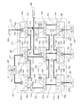
- FIG. 11 is a diagram illustrating an example of a network to which the communication device according to the first embodiment is applied.
- a wired ad hoc network 200 in FIG. 11 includes a plurality of communication devices 100a to 100i.
- the communication devices 100a to 100i are physically connected in a mesh shape (in other words, a lattice shape) by a cable (for example, a metal wire cable such as a copper cable or an optical fiber cable).
- a cable for example, a metal wire cable such as a copper cable or an optical fiber cable.
- the physical connection topology in the wired ad hoc network is arbitrary according to the embodiment and does not necessarily have to be a mesh.
- the communication device 100a has four ports 131a to 134a.
- components similar to each other may be assigned the same reference numerals except for subscripts such as “a” and “b” such as “131a” and “131b”, and detailed description thereof may be omitted.
- the mesh-like physical topology shown in FIG. 11 is realized by the following cable wiring.
- the communication devices 100a and 100d are connected by a link 215 between the ports 131a and 131d.
- the communication devices 100a and 100b are connected by a link 216 between the ports 134a and 131b.
- the communication devices 100b and 100e are connected by a link 217 between the ports 132b and 132e.
- the communication devices 100b and 100c are connected by a link 218 between the ports 134b and 131c.
- the communication devices 100c and 100f are connected by a link 219 between the ports 133c and 133f.
- the communication devices 100d and 100g are connected by a link 221 between the ports 132d and 132g.
- the communication devices 100d and 100e are connected by a link 222 between the ports 134d and 131e.
- the communication devices 100e and 100h are connected by a link 223 between the ports 133e and 133h.
- the communication devices 100e and 100f are connected by a link 224 between the ports 134e and 131f.
- the communication devices 100f and 100i are connected by a link 225 between the ports 134f and 134i.
- the communication devices 100g and 100h are connected by a link 226 between the ports 134g and 131h.
- the communication devices 100h and 100i are connected by a link 227 between the ports 134h and 131i.
- a mesh topology equivalent to that of FIG. 11 can be realized by connecting ports of combinations other than those illustrated in FIG. 11 with cables.
- the wired ad hoc network 200 is not an isolated network, but is also connected to other networks (hereinafter referred to as “external network”) such as a LAN and a WAN (Wide Area Network).
- external network such as a LAN and a WAN (Wide Area Network).
- the communication devices 100a to 100i in FIG. 11 have not only the components shown in FIG. 6 but also general-purpose LAN ports 135a to 135i as connection interfaces between the wired ad hoc network 200 and external networks, respectively.
- the general-purpose LAN ports 135a to 135i are indicated by hatching to distinguish them from the wired ad hoc network ports 131a to 134i.
- the general-purpose LAN ports 135a to 135i in FIG. 11 are wired LAN ports, a wireless LAN interface can be used instead depending on the embodiment.
- the wired ad hoc network 200 is connected to an external network as follows. That is, an L2SW (Layer 2 Switch) 202 connected to a PC (Personal Computer) 201 via a link 211 is connected to general-purpose LAN ports 135a and 135b of the communication devices 100a and 100b via links 212 and 213, respectively.
- L2SW Layer 2 Switch
- PC Personal Computer
- PCs 203, 205, and 206 are connected to general-purpose LAN ports 135c, 135g, and 135h of the communication devices 100c, 100g, and 100h via links 214, 228, and 229, respectively.
- L2SW 202 may be further connected to a router (not shown) or another PC (not shown).
- the PCs 203, 205, and 206 may also be connected to other external networks (not shown).
- FIG. 11 illustrates a wired ad hoc network 200 including nine communication devices 100a to 100i. However, depending on the embodiment, a large number of communication devices such as thousands to hundreds of thousands may be wired. An ad hoc network may be included.
- the wired ad hoc network of the first embodiment may be applied to a sensor network that is a network for collecting various information from a large number of sensors arranged everywhere.
- the wired ad hoc network may include a large number of communication devices on the order of thousands to hundreds of thousands corresponding to a large number of sensors.
- the sensor network for example, any type of sensor such as an image sensor, a temperature sensor, a humidity sensor, a pressure sensor, and an acceleration sensor is used.
- FIG. 11 also shows one example of application of the wired ad hoc network according to the first embodiment to a sensor network. That is, in FIG. 11, sensors 204 and 207 having a LAN interface are connected to general-purpose LAN ports 135e and 135i of the communication devices 100e and 100i via links 220 and 230, respectively. The sensors 204 and 207 output data indicating the sensed result as an Ethernet frame via the LAN interface. The types of these sensors 204 and 207 are arbitrary.
- a sensor and a communication device connected to the sensor via a general-purpose LAN port in soil such as fields and cliffs, underwater such as paddy fields, rivers, and seas, and structures such as walls and pillars of buildings May be embedded.
- the communication device can reliably communicate with other communication devices by wired connection. Therefore, by using the wired ad hoc network according to the first embodiment, it is possible to construct a sensor network even in an environment where wireless communication is difficult, such as in the soil, underwater, and in a structure.
- FIG. 11 The network configuration in FIG. 11 has been described above. Next, an outline of the distributed cooperative operation in the wired ad hoc network 200 in FIG. 11 will be described. Details of the operations of the individual communication devices 100a to 100i will be described later with reference to flowcharts.
- the communication device 100c receives the Ethernet frame and adds an ad hoc header to the received Ethernet frame.
- the ad hoc frame is transmitted from the communication device 100c to the communication device 100g in the wired ad hoc network 200 by autonomous distributed cooperation realized by each communication device operating according to a flowchart described later. Then, the communication device 100g removes the ad hoc header from the ad hoc frame.
- the Ethernet frame obtained as a result is output from the communication device 100g to the PC 205 via the link 228.
- each link shown in FIG. 11 is normal, it is assumed that, for example, a path including links 218, 216, 215, and 221 is selected as a transmission path from the communication apparatus 100c to the communication apparatus 100g.
- the route is selected by the following distributed cooperation.
- the communication device 100c that has received the frame from the PC 203 selects the port 131c connected to the communication device 100b via the link 218 as the frame transmission destination port. Then, the communication device 100b that has received the frame from the communication device 100c selects the port 131b connected to the communication device 100a via the link 216 as the transmission destination port of the frame.
- the communication device 100a that has received the frame from the communication device 100b selects the port 131a connected to the communication device 100d via the link 215 as the transmission destination port of the frame.
- the communication device 100d that has received the frame from the communication device 100a selects the port 132d connected to the communication device 100g via the link 221 as the transmission destination port of the frame.
- the communication device 100c selects the port 131c as the frame transmission destination port in the same manner as normal, and the communication device 100b also selects the port 131b as the frame transmission destination port in the normal manner. Then, the communication device 100a receives the frame.
- the communication device 100a is connected to only two communication devices 100b and 100d in the wired ad hoc network 200, and the link 215 between the communication devices 100d has a failure. It has occurred. Therefore, the communication device 100a cannot transmit a frame received from the communication device 100b via the link 216 to a communication device in the wired ad hoc network 200 other than the communication device 100b via a normal link.
- the communication device 100a returns the frame to the communication device 100b via the link 216 in order to notify that the frame cannot be transmitted from the communication device 100a itself. Then, the communication device 100b receives the frame transmitted by the communication device 100b itself.
- the communication device 100b recognizes that the port 131b is in the “L” state (that is, the loop state) based on the port state information associated with the communication device 100g in the routing table 121. In other words, the communication device 100b should “not transmit a frame to the port 131b connected to the communication device 100a when transmitting a frame whose final destination within the wired ad hoc network 200 is the communication device 100g”. Recognize.
- the communication device 100b searches for a normal port other than the port 131b that can be used as a frame transmission destination port. In this case, the port 132b connected to the communication device 100e via the normal link 217 is found.
- the communication device 100b transmits the frame returned from the communication device 100a to the port 132b this time. Then, the communication device 100e receives the frame.
- each link connected to the communication device 100e is normal. Therefore, for example, the communication device 100e can select the port 133e connected to the communication device 100h via the link 223 as a frame transmission destination port.
- the frame is transmitted from the port 133e and received by the communication device 100h via the link 223. Then, the communication device 100h selects the port 131h connected to the communication device 100g via the normal link 226, and transmits a frame from the port 131h.
- the communication device 100g can receive the frame. As described above, even when a failure occurs in the link 215 on the route that has been used up to now, the route is automatically switched by the distributed cooperation of the communication devices in the wired ad hoc network 200.
- the communication apparatus 100b may select the port 131b as a destination port depending on the destination of the frame. That is, as described above, in the communication device 100b, even when the port 131b is recognized as the “L” state corresponding to the communication device 100g, the communication device 100b transmits the frame addressed to the communication device 100a from the port 131b. Can be sent. As described above, according to the first embodiment, whether or not transmission of a frame from a certain port is possible is managed depending on the destination of the frame.
- FIG. 12 is a conceptual diagram illustrating an alternative route search when a failure occurs.
- FIG. 12 shows a search tree 300 in which the communication device 100c that is a transmission source in the wired ad hoc network 200 is a root node and the communication device 100g that is a transmission destination in the wired ad hoc network 200 is a leaf node in the above example. It is.
- a certain node in the search tree 300 is referred to as a “first node”, and a communication device in the wired ad hoc network 200 corresponding to the first node is referred to as a “first communication device”.
- the state of the other communication device (referred to as “second communication device” for convenience) in the entry corresponding to the destination communication device 100g is “U” state or It is assumed that the state is “E”.
- the first node has a child node corresponding to the second communication device.
- the transmission path before the failure of the link 215 described with reference to FIG. 11 is a path found corresponding to the search path 301 of FIG. 12 as a result of distributed coordination in the wired ad hoc network 200.
- the search path 301 is a path from the communication device 100c that is a root node in the search tree 300 to the communication device 100g that is a leaf node in the search tree 300 via the communication devices 100b, 100a, and 100d.
- the search path 302 includes a backtrack 303 as shown in FIG.
- switching the route described with reference to FIG. 11 corresponds to performing a depth-first search including the backtrack 303 in the search tree 300 as the entire wired ad hoc network 200”.
- the search path 302 including the backtrack 303 reaches the communication device 100g that is a leaf node, the search is successful and the frame transmission path in the wired ad hoc network 200 is established.
- the occurrence of the backtrack 303 in the communication device 100a in the search tree 300 corresponds to the communication device 100a returning a frame to the communication device 100b in the description of FIG. Then, the path from the root node to the leaf node in the search tree 300 finally found by the search path 302 of the search tree 300 becomes a new frame transmission path from the communication device 100c to the communication device 100g in the wired ad hoc network 200. Equivalent to. That is, as shown in FIG. 12, a route passing through the communication devices 100c, 100b, 100e, 100h, and 100g is found as a new frame transmission route.
- FIG. 13 is a diagram for explaining the format of a frame.
- the “ad hoc frame” according to the first embodiment is a frame transmitted and received between communication devices in the wired ad hoc network.
- the ad hoc frame 400 is a frame in which an “ad hoc header” that is a header of a specific format defined in the first embodiment is added to a general Ethernet frame 420.
- the ad hoc header 410 is information that serves as an interface between the Ethernet that is an external network and the wired ad hoc network of the first embodiment.
- the ad hoc header 410 of the first embodiment is 14 bytes as shown in FIG. 13 and includes fields of GD411, GS412, Type 413, FID414, TTL415, length 416, and FCS417.
- the ad hoc header 410 is provided by a communication device in the wired ad hoc network.
- GD field may be simply expressed as “GD”.
- 3-byte GD (Global Destination) 411 identification information (for example, node ID) for uniquely identifying a communication device that is a transmission source of a frame in the wired ad hoc network is designated in the wired ad hoc network.
- the 3-byte GS (Global Source) 412 specifies identification information (for example, a node ID) for uniquely identifying a communication device that is a frame transmission destination in the wired ad hoc network.
- the transmission source communication device in the wired ad hoc network 200 is the communication device 100c connected to the PC 203. It is.
- the destination communication device in the wired ad hoc network 200 is the communication device 100g connected to the PC 205.
- the node ID of the communication device 100c is designated as GD411. Further, the node ID of the communication device 100g is specified in the GS412.
- the values specified in the GD 411 and the GS 412 are, for example, node IDs assigned in advance to each communication device, and the node IDs may be identification numbers.
- the lower 3 bytes of the MAC address of the communication device can be used as identification information for GD411 and GS412. This is because the upper 3 bytes of the MAC address are OUI (Organizationally Unique Identifier) and the lower 3 bytes are unique within the vendor.
- OUI Organizationally Unique Identifier
- a direct transmission destination from the communication device 100c is a communication device (for example, the communication device 100b) adjacent to the communication device 100c. is there. Therefore, when explicitly distinguishing the communication device 100b that is the direct transmission destination from the communication device 100g that is the final transmission destination, the communication device 100g that is the final transmission destination in the wired ad hoc network 200. Is called a “global destination”.
- a communication device 100b adjacent to the communication device 100c that is directly connected to the communication device 100c with a cable is referred to as a “local transmission destination”.
- the communication device 100c is both a global transmission source and a local transmission source. Further, for the communication device 100g, the communication device 100c is a global transmission source, but is not a local transmission source (because the communication devices 100g and 100c are not directly connected).
- the local transmission destination has a one-to-one correspondence with the frame transmission destination port
- the local transmission source has a one-to-one correspondence with the port that received the frame.
- a value for identifying the type (classification) of the ad hoc frame 400 is designated as the 4-bit type 413.
- a value that identifies several types as exemplified below is specified in type 413.
- Data frame (a kind of ad hoc frame 400 including the Ethernet frame 420 following the ad hoc header 410)
- Some other type of control frame (a type of ad hoc frame that includes data of a predetermined format other than the Ethernet frame 420 following the ad hoc header 410).
- the control frame includes a pause request frame and a pause release frame as illustrated in FIGS.
- identification information assigned to the ad hoc frame 400 by the transmission source communication device identified by the value of the GS 412 is designated.
- the value specified in the FID 414 may be, for example, a sequence number generated by the communication device using a built-in counter circuit (not shown).
- the validity period of the ad hoc frame 400 is specified by the number of hops in the wired ad hoc network. Each time the ad hoc frame 400 hops in the wired ad hoc network, the value of the TTL 415 is counted down by the communication device.
- the initial value of the TTL 415 (that is, the value assigned by the transmission source communication device identified by the value of the GS 412) is a value (that is, 65535) in which all the bits of 2 bytes are “1” in the first embodiment. . Since such a large value is set as the initial value of the TTL 415, the first embodiment can be suitably applied to a wired ad hoc network including hundreds of thousands of communication devices. Of course, depending on the embodiment, the initial value of the TTL 415 is arbitrary.
- a value obtained by counting the length of a portion other than the ad hoc header 410 (for example, the length of the Ethernet frame 420 in the case of the ad hoc frame 400 illustrated in FIG. 13) in bytes is designated. .
- an error detection code such as a CRC (Cyclic Redundancy Check) code obtained from each field from the GD 411 to the length 416 of the ad hoc header 410 is specified in the 2-byte FCS (Frame Check Check Sequence) 417.
- CRC Cyclic Redundancy Check
- the Ethernet frame 420 includes the following fields. 6-byte MAC-DA (Media Access Control Destination Address) 421 6-byte MAC-SA (Media Access Control Source Address) 422 2 bytes type / length 423 ⁇ L3 (Layer 3) packet 424 with a variable length of 46 to 1500 bytes 4-byte FCS425
- Ethernet frame 420 Since the format of the Ethernet frame 420 is well known, detailed description thereof will be omitted. For example, in the example of FIG. 11, a specific example in which a frame is transmitted from the PC 203 to the PC 205 via the wired ad hoc network 200 will be described. It is as follows.
- the PC 203 generates an Ethernet frame 420 in which the MAC address of the PC 205 is specified in the MAC-DA 421 and the MAC address of the PC 203 itself is specified in the MAC-SA 422, and is transmitted to the communication device 100c via the link 214. Then, the communication device 100c adds the ad hoc header 410 as described above to the front of the Ethernet frame 420 to create the ad hoc frame 400.
- the ad hoc frame 400 is transmitted to the communication device 100g within the wired ad hoc network 200, and the communication device 100g outputs the Ethernet frame 420 excluding the ad hoc header 410 to the PC 205 via the link 228.
- the ad hoc frame When a value indicating a control frame is specified in the type 413 in the ad hoc header 410, the ad hoc frame includes a payload in a predetermined format other than the Ethernet frame 420 after the ad hoc header 410.
- the control frame is a pause frame 430.
- the pause frame 430 includes an ad hoc header 410 and pause control information 440.
- FIG. 13 shows two types of pause request frames and three types of pause release frames. Depending on the embodiment, only one type of pause request frame may be used, or multiple types of pause request frames may be used. Similarly, only one type of pause release frame may be used, or a plurality of types of pause release frames may be used.
- the pause control information 440 in the pause request frame may include a control type 441 indicating a pause request, one GD442, and a counter 443 indicating a value of 0 or more, like the pause control information 440a.
- the pause control information 440 in the pause request frame indicates a control type 441 indicating a pause request, a GD list 444 that is a list including one or more GDs, and a value of 0 or more, like the pause control information 440b.
- a counter 443 may be included.
- the GD list 444 may include information that can identify the GD list structure, such as the number of GD included in the list.
- the value of the counter 443 is set in the counter CT ji of the routing table 121 by the reception frame control unit 104.
- the counter 443 may be omitted.
- the reception frame control unit 104 sets a default value in the counter CT ji of the routing table 121. That is, the pause request frame may include an explicit value like the counter 443, or may implicitly specify the length of the period by a default value that is not explicitly included.
- the pause control information 440 in the pause release frame may include a control type 445 indicating pause release, one GD446, and a counter 447 indicating 0, like the pause control information 440c.
- the pause control information 440 in the pause release frame includes a control type 445 indicating pause release, a GD list 448 that is a list including one or more GDs, and a counter 447 indicating 0 as in the pause control information 440d. May be included.
- the pause control information 440 in the pause release frame may include a control type 445 indicating pause release and a counter 447 indicating 0, like the pause control information 440e.
- the pause control information 440e implicitly specifies that “pause request is canceled for all GD”.
- control type 441 or 445 may be omitted. This is because the positive counter 443 includes a pause request frame, and the zero counter 447 includes a pause release frame, so that the control type can be determined from the counter value.
- a pose frame 430 of a format other than those exemplified above may be used.
- FIG. 14 is a flowchart of frame reception processing.
- the frame reception process is started when the receiving unit 103 receives a frame.
- a frame is received at the r-th port among the x ports included in the communication apparatus 100.
- step S101 the receiving unit 103 secures an area on the buffer 102 and stores the received frame in the secured area.
- the receiving unit 103 adds a value corresponding to the size of the area secured in step S101 to the total buffer usage counter 114.
- the receiving unit 103 notifies the reception frame control unit 104 of the reception of the frame.
- this notification includes information indicating the start address of the area secured by the receiving unit 103 in step S101 and a port ID for identifying the port from which the receiving unit 103 has received a frame.
- the received frame control unit 104 that has received the notification instructs the table control unit 106 to learn the MAC table 124 described with reference to FIG.
- the MAC table 124 is learned.
- the reception frame control unit 104 determines whether or not the received frame is a pause frame. This determination is made in order to process the pause frame preferentially over the data frame. This determination is made by the reception frame control unit 104 referring to the frame type 413 stored in the buffer 102.
- step S104 If the received frame is a pause frame, the process proceeds to step S104. On the other hand, when the received frame is not a pause frame (that is, when the received frame is a data frame), the process proceeds to step S108.
- step S104 the reception frame control unit 104 determines whether the received pause frame is a pause request frame or a pause release frame based on the control type or counter value of the received pause frame. If the received pause frame is a pause request frame, the process proceeds to step S105. If the received pause frame is a pause release frame, the process proceeds to step S106.
- the pause request frame may be used for a new pause request or may be used for a pause extension request.
- the node device that has issued the first pause request in the past notifies the cancellation of the first pause request when the busy state still continues after the period specified in the pause frame representing the first pause request. Instead, the second pause request may be issued again.
- This second pause request is a pause extension request.
- step S105 the reception frame control unit 104 performs the pause setting process of FIG.
- step S106 the reception frame control unit 104 performs the pause release process of FIG. And after execution of step S105 or S106, a process transfers to step S107.
- step S107 the receiving unit 103 subtracts a value corresponding to the size of the area secured in step S101 from the total buffer usage counter 114. That is, the receiving unit 103 cancels the addition in step S102. In addition, the receiving unit 103 releases the area occupied on the buffer 102 by the received pause request frame. Then, the frame reception process ends.
- the reception frame control unit 104 determines whether or not the reception frame is addressed to the communication apparatus 100 itself. In other words, the reception frame control unit 104 determines whether or not the node ID of the communication device 100 itself matches the value of the GD 411 of the reception frame.
- step S110 If the node ID of the communication device 100 and the value of the GD 411 match, the received frame is addressed to the communication device 100 itself, and the process proceeds to step S110. On the other hand, if the node ID of the communication device 100 itself does not match the value of the GD 411, the received frame is not addressed to the communication device 100 itself. Therefore, the process proceeds to step S109.
- step S109 the reception frame control unit 104 performs the GD-specific buffer usage addition processing of FIG. Then, the process proceeds to step S110.
- step S110 the reception frame control unit 104 stores the start address of the area secured by the reception unit 103 in step S101 and the port of the port from which the frame is received in the reception queue held as internal data by the reception frame control unit 104. Add a set of IDs (that is, enqueue a set of head address and port ID). Then, the frame reception process ends.
- FIG. 15 is a flowchart of the pose setting process corresponding to step S105 in FIG.
- reception frame control section 104 stores the port that received pause frame 430 (specifically, the pause request frame in FIG. 15) as a “reception port”. Note that the reception frame control unit 104 recognizes the port from which the pause request frame is received (in other words, the adjacent node device that is the transmission source of the pause request frame) by the notification from the reception unit 103 in step S102.
- the reception frame control unit 104 extracts the value of the counter 443 from the pause control information 440 of the pause frame 430 and stores it. Note that the reception frame control unit 104 recognizes the start address of the area in the buffer 102 in which the received pause request frame is stored by the notification from the reception unit 103 in step S102. Therefore, the reception frame control unit 104 can read the content of the pause control information 440 from the buffer 102.
- the reception frame control unit 104 determines whether or not an unprocessed GD remains in the pause control information 440. If there remains a GD 442 or a GD listed in the GD list 444 that has not been subjected to the processing from step S204 onward, the process proceeds to step S204. On the other hand, when the processing after step S204 is completed for GD442 or when the processing after step S204 is completed for all GDs in the GD list 444, the pause setting processing ends.
- step S204 the reception frame control unit 104 extracts one GD determined in step S203 as unprocessed from the pause control information 440 of the received pause frame 430. That is, the reception frame control unit 104 extracts the GD 442 from the pause control information 440a or extracts one GD from the GD list 444 of the pause control information 440b.
- step S205 the reception frame control unit 104 searches the routing table 121 using the extracted GD as a search key. Subsequently, in step S206, the reception frame control unit 104 determines whether or not the extracted GD is found in the routing table 121 as a result of the search. If there is an entry including the extracted GD as the “destination” in the routing table 121, the process proceeds to step S207. Conversely, if there is no entry in the routing table 121 that includes the extracted GD as the “destination”, the process proceeds to step S209.
- step S207 the reception frame control unit 104 sets the “port state” of the reception port stored in step S201 to the “P” state in the entry of the routing table 121 found as a result of the search.
- step S208 the reception frame control unit 104 sets the “counter” of the reception port stored in step S201 to the value stored in step S202 in the entry of the routing table 121 found as a result of the search. Then, the process returns to step S203.
- the received frame control unit 104 adds a new entry to the routing table 121 in step S209. Then, the reception frame control unit 104 initializes the added entry. That is, the reception frame control unit 104 sets the GD extracted in step S204 to the “destination” of the added entry, initializes all the x “port states” to the “E” state, and sets the x “counters”. ”Are initialized to 0, and“ Pause GD ”is initialized to 0.
- step S210 the reception frame control unit 104 updates the “port state” corresponding to the reception port stored in step S201 to the “P” state in the entry added in step S209.
- step S211 the reception frame control unit 104 sets the “counter” corresponding to the reception port stored in step S201 in the entry added in step S209 to the value stored in step S202. Then, the process returns to step S203.
- the search and update of the routing table 121 by the reception frame control unit 104 is performed via the table control unit 106.
- FIG. 16 is a diagram illustrating an example of the pose setting process of FIG. 15 in the second operation example described with reference to FIGS.
- Node 3 in FIG. 2 is connected to node 2 and node 4.
- the node 3 has four ports 131 to 134. Specifically, the port 131 is connected to the node 2, and the port 132 is connected to the node 4.
- each entry of the routing table 121a stored in the node 3 includes “port state” and “counter” respectively corresponding to the four ports 131 to 134 as shown in FIG. 16 (that is, in FIG. 7). x is 4 in FIG. 16).
- FIG. 16 shows a case where the node 3 that has received a pause request frame (not shown) described with reference to FIGS. 4 and 5 performs the pause setting process of FIG.
- a node ID identifying a node 5 that is specified as the GD in the pause request frame and GD alpha.
- the reception port stored in step S201 by the node 3 is the port 132 connected to the node 4 that is the transmission source of the pause request frame.
- the node 3 takes out the GD alpha in step S204, the search in step S205, find the entry that contains the GD alpha. Therefore, the node 3 updates the found entry in steps S207 and S208.
- the found entry specifically includes the following values as in the entry E1 in FIG. “Destination” is “GD ⁇ ” representing the node 5.
- “Port states” corresponding to the ports 131 to 134 are “E”, “U”, “L”, and “L”, respectively.
- “Counters” corresponding to ports 131 to 134 are all 0.
- “Pause GD” is 0.
- step S207 the node 3 updates the “port state” corresponding to the port 132 that is the reception port from the “U” state to the “P” state.
- step S208 the node 3 updates the “counter” corresponding to the port 132 from 0 to the value C ⁇ specified in the pause request frame.
- the port 132 connected to the node 4 is selected as the transmission destination of the frame having the node 5 as the GD. This corresponds to the transmission of a frame with node 5 as GD from node 3 to node 4 at time T1 in FIG. 1 before time T4 in FIG.
- the “port state” of the entry E1 indicates that the ports 133 and 134 cannot be used as the transmission destination of the frame having the node 5 as the GD.
- the port 131 is not selected, but can be selected as a transmission destination of a frame having the node 5 as a GD.
- FIG. 4 shows that the node 3 transmits a frame having the node 5 as a GD to the node 2 after receiving the pause request frame.
- This corresponds to the “port state” of the port 131 connected to the node 2 being updated from “E” to “U” in FIG. That is, since the “E” state indicates that selection is possible, the node 3 can select the node 2 as the transmission destination of the frame having the node 5 as the GD.
- the update from “E” to “U” is performed in the received data frame processing described later.
- FIG. 17 is a flowchart of the pause release process corresponding to step S106 in FIG.
- reception frame control section 104 determines whether or not GD is specified in pause control information 440 of received pause frame 430 (specifically, the pause release frame in FIG. 17). If GD is not specified (that is, if the pause control information 440 is in the form of pause control information 440e), the process proceeds to step S302. Conversely, if there is an explicit designation of GD (that is, if pause control information 440 is in the form of pause control information 440c or 440d), the process proceeds to step S304.
- step S302 the reception frame control unit 104 updates the “port state” in all entries of the routing table 121 to the “E” state for the port that has received the pause frame 430. That is, for all GDs registered as “destination” in the routing table 121, the reception frame control unit 104 returns the “port state” of the port that received the pause frame 430 to the “E” state. Note that the reception frame control unit 104 recognizes the port from which the pause release frame has been received based on the notification from the reception unit 103 in step S102.
- step S303 the reception frame control unit 104 clears “counters” in all entries of the routing table 121 for ports that have received the pause frame 430 (that is, resets them to 0). Then, the pause release process ends.
- the reception frame control unit 104 stores the port that has received the pause frame 430 in step S304.
- the reception frame control unit 104 determines whether or not an unprocessed GD remains in the pause control information 440. If there remains a GD 446 or a GD listed in the GD list 448 that has not been subjected to the processing from step S306 onward, the process proceeds to step S306. On the other hand, when the processing after step S306 is completed for GD446 or when the processing after step S306 is completed for all GDs in the GD list 448, the pause release processing ends.
- step S306 the reception frame control unit 104 extracts one GD determined as unprocessed and determined in step S305 from the pause control information 440 of the received pause frame 430. That is, the reception frame control unit 104 extracts the GD 446 from the pause control information 440c or extracts one GD from the GD list 448 of the pause control information 440d. In step S307, the reception frame control unit 104 searches the routing table 121 using the extracted GD as a search key.
- step S308 the reception frame control unit 104 determines whether or not the extracted GD is found in the routing table 121 as a result of the search. If there is an entry including the extracted GD as a “destination” in the routing table 121, the process proceeds to step S309.
- step S305 if there is no entry in the routing table 121 that includes the extracted GD as the “destination”, the process returns to step S305. For example, as a result of deletion of an entry by aging processing, an entry may not be found in the search in step S307.
- step S309 the reception frame control unit 104 returns the “port state” of the reception port stored in step S304 to the initial state “E” in the entry of the routing table 121 found as a result of the search.
- step S310 the reception frame control unit 104 clears the “counter” of the reception port stored in step S304 in the entry of the routing table 121 found as a result of the search. Then, the process returns to step S305.
- FIG. 18 is a flowchart of the GD-specific buffer usage addition processing performed in step S109 of FIG.
- step S401 of FIG. 18 the reception frame control unit 104 extracts the GD 411 of the received frame (that is, the frame received by the reception unit 103 and stored in the buffer 102 in step S101 of FIG. 14).
- step S402 the reception frame control unit 104 searches the buffer in-use GD table 126 using the GD 411 extracted in step S401 as a search key.
- step S403 the reception frame control unit 104 determines whether an entry is found as a result of the search. If an entry is found, the process proceeds to step S404. If no entry is found, the process proceeds to step S405.
- step S404 the reception frame control unit 104 adds a value corresponding to the size of the area secured on the buffer 102 by the reception unit 103 for the received frame to the “buffer counter” of the found entry.
- the size of this area may be calculated from, for example, the value read from the “length” field 416 of the frame stored in the buffer 102 by the reception frame control unit 104.
- the reception unit 103 may notify the reception frame control unit 104 of the size of the area in step S102.
- the reception frame control unit 104 can recognize the size of the area.
- step S404 When the addition in step S404 is completed, the GD-specific buffer usage addition processing is also ended. If no entry is found in step S402, the reception frame control unit 104 adds a new entry to the buffer in use GD table 126 in step S405.
- step S406 the reception frame control unit 104 sets the GD 411 extracted in step S401 to “GD” of the added entry.
- step S ⁇ b> 407 the reception frame control unit 104 sets a value corresponding to the size of the area secured on the buffer 102 by the reception unit 103 for the received frame in the “buffer counter” of the added entry. Then, the GD-specific buffer usage addition processing is also terminated.
- the received data frame processing may be a resident process that continues to be executed while the communication apparatus 100 is powered on. That is, the reception data frame processing is started after the communication device 100 is turned on and predetermined processing such as initialization of various tables in the table storage unit 101 is completed, and thereafter the communication device 100 is turned off. May be continued.
- the reception frame control unit 104 stands by while the reception queue is empty. Then, when the reception queue is not empty, the process proceeds to step S502. As described with reference to step S110 of FIG. 14, the reception queue enqueues a set of the start address and reception port of the area on the buffer 102 in which the data frame received by the reception unit 103 is stored.
- step S502 the reception frame control unit 104 dequeues the pair of the address and port ID recorded at the head of the reception queue, and pays attention to the reception frame stored in the area starting from the dequeued address.
- the frame focused in step S502 is also simply referred to as a “reception frame”.
- the received frame control unit 104 determines whether the received frame is addressed to the communication device 100 itself. In other words, the reception frame control unit 104 determines whether or not the node ID of the communication device 100 itself matches the value of the GD 411 of the reception frame.
- the process proceeds to step S506 in FIG.
- step S504 upper transfer processing is performed. That is, in step S504, the received frame control unit 104 notifies the upper layer processing unit 105 of the head address where the received frame is stored. The reception frame control unit 104 may further notify the upper layer processing unit 105 of the start address of the Ethernet frame 420, which is the payload of the reception frame, calculated from the start address.
- the upper layer processing unit 105 reads the payload of the received frame from the buffer 102 according to the notified address, and performs appropriate processing. For example, the upper layer processing unit 105 processes data included as the L3 packet 424 in the payload of the received frame, or executes appropriate control based on the received frame.
- the upper layer processing unit 105 releases the area occupied by the received frame in the buffer 102, and subtracts a value corresponding to the size of the released area from the buffer usage total counter 114. Then, the process returns to step S501.
- step S506 the reception frame control unit 104 determines whether or not there is an entry corresponding to the reception frame in the loop detection table 122. That is, the reception frame control unit 104 searches the loop detection table 122 via the table control unit 106 using the combination of the GS 412 value and the FID 414 value of the reception frame as a search key.
- step S522 If, as a result of the search, an entry is found in which the transmission source GS i matches the value of GS 412 and FID i matches the value of FID 414 (1 ⁇ i ⁇ m), the process proceeds to step S522 in FIG. On the other hand, if the above entry is not found as a result of the search, the process proceeds to step S507 in FIG. Note that there is only one entry as described above even if it exists.
- step S507 the reception frame control unit 104 requests the port selection unit 108 to start processing for determining a destination port. Then, the port selection unit 108 searches the routing table 121 using the value of the GD 411 of the received frame via the table control unit 106.
- step S 508 the port selection unit 108 determines whether or not an entry having the value of the GD 411 as “destination” is found in the routing table 121 as a result of the search. If the entry is not found, the process proceeds to step S509. If the entry is found, the process proceeds to step S510. Note that there is only one entry, even if it is found.
- step S509 the port selection unit 108 registers a new entry in the routing table 121 via the table control unit 106.
- the destination value is set to the GD411 value of the received frame
- the “port state” of the x ports is set to the “E” state
- the “counter” of the x ports is all 0.
- “pause GD” is set to zero. Then, the process proceeds to step S510.
- one entry found as a result of the search in step S507 or an entry newly registered in step S509 is referred to as a “target entry”, and the target entry is the f-th entry in the routing table 121.
- step S510 the port selection unit 108 reflects the current port link state in the entry of interest in the routing table 121. That is, in step S510, the port selection unit 108 performs the following operation on the “port state” of the kth port for each k where 1 ⁇ k ⁇ x.
- the port selection unit 108 When the port state RP kf of the k-th port is in the “D” state, the port selection unit 108 refers to the link state L k in the port link state table 123. If the link state L k is the “C” state, the port selection unit 108 updates the port state RP kf to the “E” state. Conversely, if the link state L k is in the “D” state, the port selection unit 108 keeps the port state RP kf in the “D” state.
- the port selection unit 108 When the port state RP kf of the kth port is in a state other than the “D” state, the port selection unit 108 refers to the link state L k of the port link state table 123. If the link state L k is in the “C” state, the port selection unit 108 does not change the port state RP kf . On the contrary, if the link state L k is the “D” state, the port selection unit 108 updates the port state RP kf to the “D” state.
- the port selection unit 108 refers to the entry of interest in the routing table 121. Then, the port selection unit 108 is one of the ports other than the r-th port (1 ⁇ r ⁇ x) that has received the received frame and whose status is other than “L”, “P”, and “D” states. As the destination port.
- the states other than the “L”, “P”, and “D” states are “E” state and “U” state in other words.
- the port selection unit 108 selects a port in the “U” state in preference to a port in the “E” state in step S511. This is because the port in the “U” state has been used as a transmission destination port in the past, and since it has been confirmed in step S506 that no loop occurs, reliability has been established.
- a data frame is a unicast frame unless otherwise specified. Therefore, even if the port in the “U” state exists in the target entry, there is only one port.
- the port selection unit 108 selects a port in the “E” state in step S511 and there are a plurality of “E” state ports in the entry of interest, the port selection unit 108, for example, finds “ A port in the “E” state may be selected.
- step S512 the port selection unit 108 determines whether there is a transmission destination port selected in step S511. If there is a destination port selected in step S511, the process proceeds to step S513. If no destination port is found in step S511, the process proceeds to step S518.
- step S513 the port selection unit 108 updates the state of the transmission destination port in the entry of interest in the routing table 121 to the “U” state. For example, when the e-th port (1 ⁇ e ⁇ x) is selected as the transmission destination port in step S511, the value of the state RP ef is set to “U” in step S513.
- step S 514 the port selection unit 108 additionally registers a new entry in the loop detection table 122 via the table control unit 106. If the new entry is, for example, the (m + 1) th entry, the contents of each field of the new entry are as follows.
- the transmission source GS m + 1 is set to the value of the GS 412 of the reception frame.
- -FID m + 1 is set to the value of FID 414 of the received frame.
- OLS port OLSP m + 1 is set to r (as described above, the port that received the frame is the r-th port).
- the port state LP e (m + 1) corresponding to the selected e-th port is set to “U”, the port state LP r (m + 1) corresponding to the r-th port is set to “O”, otherwise All port states corresponding to this port are set to “E”.
- step S515 the port selection unit 108 sets the current internal timer value (that is, the current time) to the timer (not shown in FIG. 7) of the new entry added in step S514 via the table control unit 106.
- aging processing can be performed by such setting.
- the frame is transmitted to the port selected as the transmission destination port in step S511 or step S519 described later.
- the port selection unit 108 sends to the transmission frame control unit 110 the port selected as the transmission destination port and the start address in the buffer 102 of the frame to be transmitted (that is, the reception frame focused in step S502). Instruct.
- the transmission frame control unit 110 rewrites the ad hoc header 410 of the received frame on the buffer 102.
- the transmission frame control unit 110 decrements TTL 415 by 1 and recalculates FCS 417.
- the transmission frame control unit 110 performs control for transmitting the reception frame in which the ad hoc header 410 is rewritten in this way from the transmission port selected by the port selection unit 108. For example, the transmission frame control unit 110 notifies the transmission unit 111 of the size of the reception frame in which the ad hoc header 410 is rewritten and the head address in the buffer 102. The transmission frame control unit 110 also notifies the transmission unit 111 of the port ID of the selected transmission port.
- the transmission unit 111 reads the frame data from the notified start address and transmits the frame from the notified transmission port. After transmission of the frame, the process proceeds to step S517.
- step S517 the buffer release process shown in FIG. 22 is performed. Then, the process returns to step S501 in FIG.
- the port selection unit 108 determines whether the GS 412 of the received frame is equal to the own node ID. When the GS 412 of the received frame is not equal to the own node ID, the process proceeds to step S519, and when both are equal, the process proceeds to step S520.
- step S518 is executed when it is determined in step S506 that there is no entry corresponding to the received frame in the loop detection table 122. Therefore, as will be described later, if the aging time of the loop detection table 122 is appropriately set in consideration of the time taken to loop the frame in the ad hoc network, before the frame loops back to its own node. Since no entry is lost from the loop detection table 122, the process proceeds to step S519, and step S520 is not executed.
- step S519 the port selection unit 108 selects the r-th port that has received the received frame as the transmission port. Then, the process proceeds to step S515 described above. Accordingly, the received frame is transmitted from the r-th port in step S516.
- the port at which the r-th port returns a received frame in step S519. Selected as.
- step S520 the port selection unit 108 notifies the upper layer processing unit 105 of the transmission failure via the transmission frame control unit 110.
- the notification of the transmission failure to the upper layer processing unit 105 may include, for example, the head address in the buffer 102 of the received frame. Then, the process proceeds to step S517.
- step S506 determines that there is an entry corresponding to the received frame in the loop detection table 122. That is, the processing in FIG. 21 is processing when a unicast frame transmitted by the communication device 100 in the past loops back in the wired ad hoc network and returns to the communication device 100 and is received at the r-th port.
- the processing in the communication device 100b that has received the frame from the communication device 100a after the backtrack 303 on the search path 302 corresponds to FIG.
- the port selection unit 108 refers to the entry detected in the loop detection table 122 by the search in step S506, reads the value of the OLS port from the entry, and recognizes the OLS port. For example, the reception frame control unit 104 may notify the port selection unit 108 of the address of the entry detected by the search in step S506, so that the port selection unit 108 can refer to the entry.
- step S523 the port selection unit 108 changes the port state in the “U” state to the “L” state in the entry of the loop detection table 122 detected in step S506.
- step S523 is a step executed for a unicast frame, only one of the port states LP 1i to LP xi in the i-th entry has the value “U”. .
- the value of the port state LP ti of the t-th (1 ⁇ t ⁇ x) port is “U”.
- the port is set in step S523.
- the value of the state LP ti is “U”.
- the value of the port state LP ti is updated from “U” to “L”.
- step S524 the port selection unit 108 searches for an entry in the routing table 121 corresponding to the value of the GD 411 of the received frame via the table control unit 106.
- the aging period of the routing table 121 (that is, the validity period of each entry) is longer than the aging period of the loop detection table 122. Therefore, in step S524, as a result of the search, it is guaranteed that one entry is always hit.
- the aging period of the routing table 121 may be a relatively long time such as 225 seconds.
- the aging period of the loop detection table 122 is preferably a relatively short time, for example, less than 1 second. The reason is that one entry in the routing table 121 corresponds to one communication device in the wired ad hoc network, whereas one entry in the loop detection table 122 corresponds to one ad hoc frame 400.
- the aging period of the loop detection table 122 is set to a relatively short time.
- an appropriate value as the length of the aging period of the loop detection table 122 is preferably determined in consideration of the time taken for the loop in the wired ad hoc network, for example, by conducting a preliminary experiment.
- step S524 the value of GD411 of the received frame is a match with the value of the destination GD j in the routing table 121.
- step S525 the port selection unit 108 reflects the current port link state in the entry detected in step S524 of the routing table 121. Since the process of step S525 is the same as that of step S510, description is abbreviate
- the port selection unit 108 sets the “port state” of the t-th port of interest in the entry detected in step S524 of the routing table 121 to the “L” state. That is, regarding the t-th port changed from the “U” state to the “L” state in the loop detection table 122 in step S523, the state is also set to “L” in the routing table 121 in step S526. Specifically, in the j-th entry of the routing table 121, the value of the port state RP tj of the t-th port is updated to “L”.
- the communication apparatus 100 When the communication apparatus 100 receives a frame that loops back in the wired ad hoc network through the above steps S523 to S526, a frame that has the same destination as the returned frame is referred to from the previous destination port. It will not be sent. That is, the communication apparatus 100 learns the port where the loop occurs, and thereafter refrains from transmitting to the port where the loop occurs. As a result, useless traffic is reduced as a whole in the wired ad hoc network.
- step S527 the port selection unit 108 searches for the jth entry in the routing table 121 (that is, the entry hit in step S524), and searches for a port that satisfies both of the following two conditions.
- -It is not the OLS port OLSP i in the i-th entry of the loop detection table 122 detected in step S506.
- “Port status” is “E” status.
- the port selection unit 108 has not yet tried as a transmission destination port for transmission other than the port that first received the ad hoc frame 400 from the transmission source GS i in which the FID i and the destination GD j are specified. And looking for a port that is currently available (ie, not in the “D” or “P” state).
- step S528 the port selection unit 108 determines whether a port in the “E” state is found as a result of the search in step S527. If no port is found, the process proceeds to step S533. In step S529, the process proceeds to step S529.
- step S529 the port selection unit 108 selects any one of the ports in the “E” state found in step S527 (for example, the first found port) as the transmission destination port. Then, the port selection unit 108 sets the state of the corresponding port selected as the transmission destination port to “U” in the j-th entry of the routing table 121.
- step S529 the value of the state RP gj of the g-th port in the j-th entry of the routing table 121 hit in step S524 is “ U ".
- step S530 the port selection unit 108 further sets the port in the loop detection table 122 to the “U” state. That is, in the i-th entry of the loop detection table 122 found in step S506, the value of the port state LP gi of the g-th port selected in step S529 as the transmission destination port is set to “U”. Then, the process proceeds to step S531.
- step S531 the frame is transmitted to the port selected as the transmission destination port in step S529 or step S534 described later.
- the details of step S531 are the same as step S516, and thus the description thereof is omitted.
- step S532 the buffer release process of FIG. 22 is performed. Then, the process returns to step S501 in FIG.
- step S533 the port selection unit 108 determines whether the GS 412 of the received frame is equal to its own node ID. When the GS 412 of the received frame is not equal to its own node ID, the process proceeds to step S534, and when both are equal, the process proceeds to step S535.
- step S534 the port selection unit 108 selects the OLS port recognized in step S522 as the transmission destination port. Then, the process proceeds to step S531.
- This step S534 is executed when a frame that can be transmitted is not found even if an attempt is made to transmit a frame received at the r-th port.
- the “transmittable port” specifically refers to a port that is not in the “L” state, the “D” state, or the “P” state other than the OLS port that first received the frame of the same FID. That is.
- step S534 is executed. Therefore, the communication apparatus 100 sets the OLS port as the transmission destination port in order to return the received frame.
- the communication apparatus 100 can notify the adjacent communication apparatus connected to the OLS port that “the communication apparatus 100 has a dead path”.
- the adjacent communication device that has received the returned frame recognizes, based on the loop detection table 122, that “the frame addressed to the destination GD j will loop even if it is transmitted to the port connected to the communication device 100”. be able to.
- the link 217 between the communication device 100e and the communication device 100e is in a link-down state in the communication device 100b that detects the loop by receiving the frame returned from the communication device 100a by the backtrack 303. .
- backtracking occurs in the communication device 100b. That is, in step S534, the communication device 100b selects the port 134b connected to the communication device 100c as a transmission destination port.
- the communication device 100c receives the frame returned from the communication device 100b. Therefore, the communication apparatus 100c recognizes that “the port 131c connected to the communication apparatus 100b is inappropriate as the transmission destination port of the ad hoc frame 400 in which the node ID of the communication apparatus 100g is set to GD411”. That is, in the routing table 121 of the communication device 100c, the state of the port 131c associated with the node ID of the communication device 100g is set to “L”.
- the communication apparatus 100c selects the port 133c different from the port 131c by step S529.
- a new transmission path is found by repeating backtracking a plurality of times in the search tree 300 (Note that a new transmission path is found only after backtracking once in the search path 302 of FIG. 12).
- step S535 the port selection unit 108 notifies the upper layer processing unit 105 of the transmission failure via the transmission frame control unit 110. Then, the process proceeds to step S532. Note that step S535 is executed when all of the search tree 300 in FIG. 12 has been searched. After notification of transmission failure, the process proceeds to step S532.
- steps S529 to S531 As described above, when a loop occurs, another new transmission path is tried in steps S529 to S531, or a backtrack occurs in steps S534 and S531. Note that switching to a new transmission path in steps S529 to S531 is performed in, for example, several ⁇ s when each unit in the communication apparatus 100 is realized by an FPGA.
- the transmission path can be transmitted in a very short time even when viewed as the entire wired ad hoc network. Switching is complete. As described above, according to the first embodiment, when a loop occurs due to a failure or for other reasons, switching of a frame transmission path is realized at a very high speed.
- the communication apparatus 100 may discard the frame based on the value of the TTL 415 in the routing process. That is, when the value of the TTL 415 of the received frame is 1, for example, processing may be performed as follows. In FIG. 21, the processes of steps S529 to S531, and S534 are omitted. In FIG. 20, processes other than steps S506 and S517 are omitted.
- the process when the value of the TTL 415 of the received frame is 1 may be included as an exception process in the frame reception process of FIG.
- the TTL 415 check may be performed as described below, for example, after the FCS 417 check and before the enqueue to the reception queue in step S110.
- the reception frame control unit 104 checks the FCS 417 of the received frame, for example, between steps S102 and S103 in FIG. When the FCS 417 is inconsistent with the ad hoc header 410, the reception frame control unit 104 instructs the reception unit 103 to perform the same processing as in step S107. As a result, the frame is discarded and the processing of FIG.
- the reception frame control unit 104 may subsequently determine whether or not the value of the TTL 415 is 1. When the value of the TTL 415 is 1, the reception frame control unit 104 instructs the reception unit 103 to perform the same process as in step S107. As a result, the frame is discarded and the processing of FIG.
- the reception frame control unit 104 performs the processing from step S103 onward.
- the processing of FIGS. 19 to 21 is performed only for a frame with TTL 415 larger than 1. Done.
- exception processing according to the TTL 415 and the FCS 417 is appropriately performed according to the embodiment.
- 19 to 21 show processing related to a frame received at a wired ad hoc network port such as the port 131a in FIG. 11, but the communication apparatus 100 receives data at a general-purpose LAN port (for example, the general-purpose LAN port 135a). Further processing related to a frame to be performed may be performed.
- the upper layer processing unit 105 processes the Ethernet frame 420.
- the upper layer processing unit 105 also processes the Ethernet frame 420 destined for the communication device 100 itself.
- an Ethernet frame 420 destined for another communication device is provided with an ad hoc header 410 by the transmission frame control unit 110 and transmitted from one of the wired ad hoc network ports.
- an entry is added to the loop detection table 122 as in step S514 of FIG.
- Ethernet frame 420 When the upper layer processing unit 105 generates the Ethernet frame 420, the Ethernet frame 420 is subjected to any of the following processing according to the MAC-DA 421. An Ethernet frame 420 is transmitted from the general-purpose LAN port 135. An ad hoc header 410 is attached to the Ethernet frame 420 and transmitted from one of the wired ad hoc network ports. At that time, an entry is also added to the loop detection table 122 as in step S514 of FIG.
- FIG. 22 is a flowchart of buffer release processing.
- the buffer release process is performed when a transmission destination port is determined for the frame received by the communication apparatus 100 and the frame is transferred, or when there is no appropriate transmission destination port.
- the processing in FIG. 22 may be performed by, for example, the transmission unit 111 when a transmission destination port is determined, or when a transmission failure is notified to the upper layer processing unit 105 because there is no transmission destination port.
- the upper layer processing unit 105 may perform this.
- the transmission frame control unit 110 may perform the process of FIG.
- step S 601 a value corresponding to the size of the area occupied by the received frame in the buffer 102 is subtracted from the buffer usage total amount counter 114. Subsequently, in step S602, the GD 411 of the received frame stored in the buffer 102 is extracted.
- step S603 the buffer-in-use GD table 126 is searched using the extracted GD411 as a search key. As a result of the search, one entry is always found.
- step S604 a value corresponding to the size of the area reserved for the received frame is subtracted from the “buffer counter” of the entry found as a result of the search.
- step S605 it is determined whether or not the value of the subtracted “buffer counter” is zero. When the value of “buffer counter” is 0, the process proceeds to step S606. When the value of “buffer counter” is not 0, the process proceeds to step S607.
- step S606 the entry found as a result of the search in step S603 is deleted from the buffer in use GD table 126.
- step S607 the area occupied by the received frame in the buffer 102 is released, and the buffer release process ends.
- FIG. 23 and FIG. 24 are flowcharts of data frame transmission processing performed when the communication apparatus 100 transmits a frame by becoming a GS.
- the transmission frame control unit 110 determines the value of the GD 411 and the payload created by the upper layer processing unit 105 in the buffer 102 (specifically, ad hoc as a result of the upper layer protocol processing by the upper layer processing unit 105).
- An Ethernet frame 420) that is a payload of the frame 400 is acquired.
- the upper layer processing unit 105 may notify the transmission frame control unit 110 of the payload by notifying the transmission frame control unit 110 of the beginning address of the payload.
- step S702 the transmission frame control unit 110 obtains the length of the payload as a value set to the length 416 of the data frame (that is, the ad hoc frame 400).
- step S703 the transmission frame control unit 110 sets its own node ID in the GS 412 of the data frame to be transmitted. Further, in step S704, the transmission frame control unit 110 generates a new FID and sets the generated value in the FID 414 of the data frame.
- step S ⁇ b> 705 the transmission frame control unit 110 sets a value indicating “data frame” as the data frame type 413. Further, in step S706, the transmission frame control unit 110 appropriately sets a value for each field in the other ad hoc header 410. Thus, the completed data frame is stored in the buffer 102.
- step S707 the transmission frame control unit 110 adds a value corresponding to the size of the data frame (that is, the size of the area occupied by the data frame in the buffer 102) to the total buffer usage counter 114.
- step S708 the transmission frame control unit 110 requests the port selection unit 108 to specify the value of the GD 411 and start processing for determining the transmission port. Then, the port selection unit 108 searches the routing table 121 using the designated GD411 value.
- step S709 the port selection unit 108 determines whether an entry including the value of GD411 as “destination” is registered in the routing table 121 according to the search result in step S708. If the entry has been registered, the process proceeds to step S711 in FIG. If no entry is found, the process proceeds to step S710.
- step S710 the port selection unit 108 newly registers an entry including the value of the GD 411 as “destination” in the routing table 121. Details of step S710 are the same as step S509 in FIG.
- step S708 one entry found as a result of the search in step S708 or an entry newly registered in step S710 is referred to as a “target entry”.
- step S711 in FIG. 24 the port selection unit 108 reflects the current port link state in the entry of interest in the routing table 121. Details of step S711 are the same as step S510 of FIG.
- the port selection unit 108 refers to the entry of interest in the routing table 121. Then, the port selection unit 108 selects one of the ports other than the “L”, “P”, and “D” states as the transmission destination port. For the same reason as described with reference to step S511 in FIG. 20, the port selection unit 108 preferably selects a port in the “U” state in preference to a port in the “E” state.
- step S713 the port selection unit 108 determines whether there is a transmission destination port selected in step S712. If there is a destination port selected in step S712, the process proceeds to step S714. If no destination port is found in step S712, the process proceeds to step S719. When the transmission destination port is not found, the port selection unit 108 notifies the transmission frame control unit 110 that the transmission destination port has not been found.
- step S714 the port selection unit 108 updates the state of the destination port in the entry of interest in the routing table 121 to the “U” state. Details of step S714 are the same as step S513 of FIG.
- step S ⁇ b> 715 the port selection unit 108 additionally registers a new entry in the loop detection table 122 via the table control unit 106. If the new entry is, for example, the (m + 1) th entry, the contents of each field of the new entry are as follows.
- the transmission source GS m + 1 the own node ID of the communication device 100 is set.
- FID m + 1 the value generated in step S704 in FIG. 23 is set.
- a dummy value that is not used as a port ID is set in the OLS port OLSP m + 1 .
- the port state LP e (m + 1) corresponding to the e-th port selected as the destination port is set to “U”, and the port states corresponding to the other ports are all set to “E”.
- step S715 the process proceeds to step S716.
- step S716 the port selection unit 108 sets the current internal timer value (that is, the current time) to the timer (not shown in FIG. 7) of the new entry added in step S715 via the table control unit 106.
- the frame is transmitted to the port selected as the transmission destination port in step S712.
- the port selection unit 108 notifies the transmission frame control unit 110 of the port selected as the transmission destination port.
- the transmission frame control unit 110 notifies the transmission unit 111 of the size of the data frame and the head address in the buffer 102.
- the transmission frame control unit 110 also notifies the transmission unit 111 of the port ID of the selected transmission port.
- the transmission unit 111 reads the frame data from the notified start address and transmits the frame from the notified transmission port. After transmission of the frame, the process proceeds to step S718.
- step S718 the transmission frame control unit 110 subtracts a value corresponding to the size of the data frame (that is, the value added in step S707) from the total buffer usage counter 114. Then, the data frame transmission process ends.
- the transmission frame control unit 110 notifies the upper layer processing unit 105 of transmission failure in step S719.
- This notification of transmission failure may include, for example, the head address of the payload notified from the upper layer processing unit 105 in step S701.
- step S720 the data frame is discarded. That is, the area on the buffer 102 in which the data frame is stored is released.
- the transmission frame control unit 110 removes the entire data frame that is the ad hoc frame 400 from the buffer 102. It may be deleted.
- the ad hoc header 410 may be deleted by the transmission frame control unit 110, and the upper layer processing unit 105 that has received the notification of transmission failure may delete the payload (for example, the Ethernet frame 420).
- step S720 a data frame that failed to be transmitted because a transmittable port is not found is discarded. Then, the process proceeds to step S718 described above.
- FIG. 25 is a flowchart of pause control processing performed by the communication apparatus 100 for the communication apparatus 100 itself. For example, the process of FIG. 25 may be periodically executed at a predetermined interval.
- step S801 the busy detection unit 113 refers to the value of the pause state SS in the pause state management table 125, and determines whether or not the communication device 100 is in the pause state.
- the process proceeds to step S804.
- the process proceeds to step S802.
- step S802 the busy detection unit 113 determines whether or not the communication device 100 itself is busy. For example, if the value of the total buffer usage counter 114 exceeds a predetermined threshold, the busy detecting unit 113 determines that “the communication device 100 is busy”, and the process proceeds to step S803. On the other hand, if the value of the total buffer usage counter 114 is equal to or less than the above threshold, the busy detection unit 113 determines that “the communication device 100 itself is not busy” and ends the process of FIG.
- condition regarding the determination of the busy state may be any condition according to the embodiment regarding the resource usage status.
- the busy detection unit 113 may determine whether or not the communication device 100 itself is busy in consideration of the usage rate of the MPU.
- step S803 a pause request frame transmission process is performed, and a pause request frame is transmitted to each adjacent node adjacent to the communication device 100.
- the pause request frame transmission process may be the process of FIG. 26 or the process of FIG.
- step S803 is executed when the busy detection unit 113 detects that the communication apparatus 100 that has not been busy so far has newly entered the busy state.
- step S801 when the value of the pause state SS is “P”, in step S804, the busy detection unit 113 determines whether or not the communication device 100 itself is busy by the same method as in step S802. When the busy detection unit 113 determines that “the communication device 100 is busy”, the process proceeds to step S806. Conversely, if the busy detection unit 113 determines that “the communication device 100 itself is not busy”, the process proceeds to step S805.
- step S805 a pause release frame transmission process is performed, and a pause release frame is transmitted to each adjacent node adjacent to the communication apparatus 100.
- the pause release frame process may be the process of FIG. 28, the process of FIG. 29, or the process of FIG.
- step S805 is a process for issuing a notification to the adjacent node device for canceling a pause request issued in the past to the adjacent node device. That is, the process of step S805 is a process for notifying the adjacent node of the recovery when the communication apparatus 100 recovers from the busy state earlier than predicted. After execution of step S805, the process of FIG. 25 ends.
- step S ⁇ b> 806 the busy detection unit 113 determines the difference between the current timer value (that is, the current time) supplied from the timer 109 and the pause start time StartTime of the pause state management table 125 as the counter SCount of the pause state management table 125. Compare with the current timer value (that is, the current time) supplied from the timer 109 and the pause start time StartTime of the pause state management table 125 as the counter SCount of the pause state management table 125. Compare with the current timer value (that is, the current time) supplied from the timer 109 and the pause start time StartTime of the pause state management table 125 as the counter SCount of the pause state management table 125.
- step S807 the busy detection unit 113 determines whether the difference has already reached the value of the counter SCount in the pause state management table 125. If the difference has already reached the value of the counter SCount, the communication device 100 itself still recovers from the busy state even though the time requested by the communication device 100 to the adjacent node device in the past pause request has already passed. That is not possible. Accordingly, at this time, the process proceeds to step S808.
- step S808 pause request frame transmission processing is performed.
- the pause request frame transmission process may be the process of FIG. 26 or the process of FIG. After execution of step S808, the process of FIG. 25 ends.
- FIG. 26 is a flowchart of a first example of pause request frame transmission processing.
- the process of FIG. 26 is started in response to an instruction from the busy detection unit 113 to the pause control unit 112.
- step S ⁇ b> 901 the pause control unit 112 sets the current time indicated by the timer 109 to the pause start time StartTime of the pause state management table 125.
- the pause control unit 112 sets the pause state SS of the pause state management table 125 to the “P” state.
- step S902 the pause control unit 112 performs a pause target GD determination process.
- the details of the pause target GD determination process vary depending on the embodiment, and some examples will be described later with reference to FIGS.
- the pause control unit 112 determines one or more GDs as the pause target GD (that is, the GD specified in the pause request frame).
- step S903 the pause control unit 112 sets “pause GD” to a value indicating “selected” in each entry corresponding to one or more GDs determined in step S902 in the routing table 121 (FIG. 7 is set to “1”).
- step S904 the pause control unit 112 determines a pause counter value (that is, the value of the counter 443 set in the pause request frame) according to the busy status notified from the busy detection unit 113. Then, the pause control unit 112 sets the determined value also in the counter SCount of the pause state management table 125.
- a pause counter value that is, the value of the counter 443 set in the pause request frame
- the busy detection unit 113 when the pause detection unit 113 instructs the pause control unit 112 in step S803 or S808 of FIG. 25 to start the pause request frame transmission process, the busy detection unit 113 notifies the pause control unit 112 of a value indicating the busy situation. Also good.
- the value indicating the busy status is, for example, a value read by the busy detecting unit 113 from the buffer usage total amount counter 114, a usage rate of the MPU, or a score calculated based on both. Therefore, the pause control unit 112 can determine the value of the counter 443 according to the busy situation.
- the pause control unit 112 may set a uniform default value for the counter 443 and the counter SCount based on the situation “the communication device 100 is in a busy state”.
- the pause control unit 112 In the next step S905, the pause control unit 112 generates a pause request frame including a list including all the GDs determined in step S902 and the pause counter value determined in step S904. That is, the pause control unit 112 generates a pause frame 430 including the pause control information 440b of FIG. The pause control unit 112 sets a value indicating a pause frame in the pause request frame type 413.
- step S906 the pause control unit 112 requests the transmission frame control unit 110 to transmit the generated pause request frame. Then, the transmission frame control unit 110 instructs the transmission unit 111 with all ports of the communication device 100 as transmission destination ports. Therefore, the transmission unit 111 transmits the generated pause request frame from all ports.
- the pause control unit 112 acquires and stores the current time from the timer 109 in step S907.
- the pause control unit 112 determines whether there is an unprocessed one or more GDs determined in step S902 that have not yet been processed in steps S909 and after. If there is an unprocessed GD, step S909 is subsequently executed. If all the GDs determined in step S902 have been processed after step S909, the pause request frame transmission process ends.
- step S909 the pause control unit 112 selects one unprocessed GD from the one or more GDs determined in step S902.
- step S910 the pause control unit 112 searches the pause history table 127 using the GD selected in step S909 as a search key.
- step S911 the pause control unit 112 determines whether an entry is found as a result of the search in step S910. If an entry is found, the process proceeds to step S912. If no entry exists, the process proceeds to step S913.
- step S912 the pause control unit 112 sets the time acquired in step S907 to the “pause request frame transmission time” of the entry found as a result of the search in step S910. Then, the process returns to step S908.
- step S913 the pause control unit 112 adds a new entry having the GD selected in step S909 and the time acquired in step S907 to the pause history table 127. Then, the process returns to step S908.
- FIG. 27 is a flowchart of the second example of the pause request frame transmission process. The processing of FIG. 27 is also triggered by an instruction from the busy detection unit 113 to the pause control unit 112.
- step S1001 the pause control unit 112 sets the current time indicated by the timer 109 to the pause start time StartTime of the pause state management table 125.
- the pause control unit 112 sets the pause state SS of the pause state management table 125 to the “P” state.
- step S1002 the pause control unit 112 performs a pause target GD determination process.
- the pause target GD determination process may be the process shown in any of FIGS.
- the pause control unit 112 determines one or more GDs as the pause target GD (that is, the GD specified in the pause request frame).
- step S1003 the pause control unit 112 sets “pause GD” to a value indicating “selected” in each entry corresponding to one or more GDs determined in step S1002 in the routing table 121 (FIG. 7 is set to “1”).
- step S1004 the pause control unit 112 determines a pause counter value according to the busy status notified from the busy detection unit 113, and sets the determined value in the counter SCount of the pause state management table 125 as well.
- the details of step S1004 are the same as step S904.
- step S1005 the pause control unit 112 determines whether there is an unprocessed one or more GDs determined in step S1002 that have not yet been processed in step S1006. If there is an unprocessed GD, step S1006 is subsequently executed. If all the GDs determined in step S1002 have been processed after step S1006, the pause request frame transmission process ends.
- step S1006 the pause control unit 112 selects one unprocessed GD from the one or more GDs determined in step S1002.
- step S1007 the pause control unit 112 generates a pause request frame including one GD selected in step S1006 and the pause counter value determined in step S1004. That is, the pause control unit 112 generates a pause frame 430 including the pause control information 440a of FIG.
- the pause control unit 112 sets a value indicating a pause frame in the pause request frame type 413.
- step S1008 the pause control unit 112 requests the transmission frame control unit 110 to transmit the generated pause request frame. Then, the transmission frame control unit 110 instructs the transmission unit 111 with all ports of the communication device 100 as transmission destination ports. Therefore, the transmission unit 111 transmits the generated pause request frame from all ports.
- step S1009 the pause control unit 112 acquires the current time from the timer 109 and stores it.
- step S1010 the pause control unit 112 searches the pause history table 127 using the GD selected in step S1006 as a search key.
- step S1011 pause control unit 112 determines whether an entry is found as a result of the search in step S1010. If an entry is found, the process proceeds to step S1012. If no entry exists, the process proceeds to step S1013.
- step S1012 the pause control unit 112 sets the time acquired in step S1009 to the “pause request frame transmission time” of the entry found as a result of the search in step S1010. Then, the process returns to step S1005.
- step S1013 the pause control unit 112 adds a new entry having the GD selected in step S1006 and the time acquired in step S1009 to the pause history table 127. Then, the process returns to step S1005.
- FIG. 28 is a flowchart of a first example of pause release frame transmission processing. The process in FIG. 28 is started in response to an instruction from the busy detection unit 113 to the pause control unit 112.
- step S1101 the pause control unit 112 clears the pause start time StartTime of the pause state management table 125.
- step S1102 the pause control unit 112 clears the value of the counter SCount in the pause state management table 125.
- step S1103 the pause control unit 112 sets the pause state SS of the pause state management table 125 to the “N” state (that is, the normal state).
- step S1104 the pause control unit 112 sets “pause GD” to a value indicating “non-selection” (specifically, “0” in the first embodiment) in all entries of the routing table 121. To do.
- step S1105 the pause control unit 112 sets a value indicating that the frame is a pause release frame in the control type 445, and generates a pause release frame including pause control information 440e in which 0 is set as the counter 447.
- the pause controller 112 sets a value indicating a pause frame in the pause release frame type 413.
- the pause control unit 112 requests the transmission frame control unit 110 to transmit the pause release frame generated in step S1105. Then, the transmission frame control unit 110 determines all ports as transmission destination ports and controls the transmission unit 111. The transmission unit 111 transmits the generated pause release frame from all ports in accordance with the control by the transmission frame control unit 110. That is, the transmitter 111 transmits a pause release frame to all adjacent nodes. Then, the pause release frame transmission process in FIG. 28 ends.
- FIG. 29 is a flowchart of a second example of pause release frame transmission processing.
- the processing in FIG. 29 is also triggered by an instruction from the busy detection unit 113 to the pause control unit 112.
- the pause control unit 112 clears the pause start time StartTime in the pause state management table 125.
- step S1202 the pause control unit 112 clears the counter value SCount in the pause state management table 125.
- step S1203 the pause control unit 112 sets the pause state SS of the pause state management table 125 to the “N” state (that is, the normal state).
- step S1204 the pause control unit 112 initializes the “GD list” to be empty.
- This GD list is local data used by the pause control unit 112 in the processing of FIG.
- step S1205 the pause control unit 112 determines whether or not all the entries in the routing table 121 have been noticed, that is, whether or not the processing from step S1206 has been performed on all entries. If entries that have not yet been processed in step S1206 remain in the routing table 121, the process proceeds to step S1206. If all entries have been noticed, the process proceeds to step S1210.
- step S1206 the pause control unit 112 selects one entry that has not been noticed in the routing table 121, and pays attention to the selected entry.
- target entry the entry selected in step S1206 is referred to as “target entry”.
- step S ⁇ b> 1207 the pause control unit 112 determines whether the value of “pause GD” is a value indicating “selected” in the entry of interest.
- the “destination” GD of the entry of interest is the GD specified in the pause request frame once transmitted by the communication apparatus 100. Therefore, the process proceeds to step S1208.
- the “destination” GD of the entry of interest is not the GD specified in the pause request frame transmitted once by the communication apparatus 100. Accordingly, the GD of the “destination” of the entry of interest is not a target for notification of cancellation in the first place, and the process returns to step S1205.
- step S1208 the pause control unit 112 sets “pause GD” to a value indicating “non-selection” in the entry of interest in the routing table 121.
- step S1209 the pause control unit 112 adds a GD included in the target entry of the routing table 121 as a “destination” to the GD list. Then, the process returns to step S1205.
- the pause control unit 112 when paying attention to all entries in the routing table 121, the pause control unit 112 generates a pause release frame in step S1210. Specifically, the pause control unit 112 includes the GD list finally obtained by adding the GD in step S1209 after initialization in step S1204 as the GD list 448, and sets 0 as the counter 447. Generate a pause release frame. That is, the pause control unit 112 generates a pause frame 430 that includes pause control information 440d. The pause controller 112 sets a value indicating a pause frame in the pause release frame type 413.
- the pause control unit 112 requests the transmission frame control unit 110 to transmit the pause release frame generated in step S1210. Then, the transmission frame control unit 110 determines all ports as transmission destination ports and controls the transmission unit 111. The transmission unit 111 transmits the generated pause release frame from all ports in accordance with the control by the transmission frame control unit 110. That is, the transmitter 111 transmits a pause release frame to all adjacent nodes. Then, the pause release frame transmission process in FIG. 29 ends.
- FIG. 30 is a flowchart of a third example of pause release frame transmission processing.
- the processing in FIG. 30 is also triggered by an instruction from the busy detection unit 113 to the pause control unit 112.
- the pause control unit 112 clears the pause start time StartTime in the pause state management table 125.
- step S1302 the pause control unit 112 clears the counter value SCount in the pause state management table 125.
- step S1303 the pause control unit 112 sets the pause state SS of the pause state management table 125 to the “N” state (that is, the normal state).
- step S1304 the pause control unit 112 determines whether or not all the entries in the routing table 121 have been noticed, that is, whether or not the processing from step S1305 has been performed on all entries. If entries that have not yet been processed in step S1305 remain in the routing table 121, the process proceeds to step S1305, and when all entries have been noticed, the pause release frame transmission process ends.
- step S1305 the pause control unit 112 selects one entry that has not been focused on in the routing table 121, and pays attention to the selected entry.
- target entry the entry selected in step S1305 is referred to as “target entry”.
- step S1306 the pause control unit 112 determines whether the value of “pause GD” is a value indicating “selected” in the entry of interest.
- the “destination” GD of the entry of interest is the GD specified in the pause request frame once transmitted by the communication apparatus 100. Therefore, the process proceeds to step S1307.
- the “destination” GD of the entry of interest is not the GD specified in the pause request frame transmitted once by the communication apparatus 100. Accordingly, the GD of the “destination” of the entry of interest is not a target for notification of cancellation in the first place, and the process returns to step S1304.
- step S1307 the pause control unit 112 sets “pause GD” to a value indicating “non-selection” in the entry of interest in the routing table 121.
- step S 1308 the pause control unit 112 generates a pause release frame in which the GD included as the “destination” in the entry of interest in the routing table 121 is included as the GD 446 and 0 is set as the counter 447. That is, the pause control unit 112 generates a pause frame 430 including the pause control information 440c.
- the pause controller 112 sets a value indicating a pause frame in the pause release frame type 413.
- step S1309 the pause control unit 112 requests the transmission frame control unit 110 to transmit the pause release frame generated in step S1308. Then, the transmission frame control unit 110 determines all ports as transmission destination ports and controls the transmission unit 111. The transmission unit 111 transmits the generated pause release frame from all ports in accordance with the control by the transmission frame control unit 110. That is, the transmitter 111 transmits a pause release frame to all adjacent nodes. Then, the process returns to step S1304.
- pause target GD determination process executed to determine the GD (hereinafter referred to as “pause target”) designated in the pause request frame in step S902 of FIG. 26 or step S1002 of FIG. 27 will be described in detail. explain.
- FIG. 31 is a flowchart of a first example of pause target GD determination processing.
- the process of FIG. 31 is a process that prioritizes reducing the influence on other nodes. Further, since only one GD is determined as a pause target in the process of FIG. 31, the process of FIG. 31 is particularly suitable for the format of the pause control information 440a of FIG.
- step S1401 the pause control unit 112 sorts the entries in the buffer in use GD table 126 in ascending order of the “buffer counter”. In step S1402, the pause control unit 112 selects the GD of the first entry in the buffer-in-use GD table 126. That is, the pause control unit 112 selects the GD having the smallest “buffer counter” value.
- the pose control unit 112 determines whether or not to consider the history of which GD has been selected as the pose target so far when determining the pose target this time.
- a value that specifies whether or not to consider history may be set. Specifically, two values such as “history considering mode” and “history non-use mode” may be set. Any one of the two operation modes may be set in the communication apparatus 100. In that case, the pause control unit 112 determines in step S1403 according to the value of the operation mode.
- the communication device 100 may be a device that is fixedly determined to operate in the history consideration mode or the history non-use mode.
- the pause control unit 112 performs the determination in step S1403 according to the value of the operation mode that is implicitly fixed.
- step S1405 the process proceeds to step S1404.
- step S1404 the pause control unit 112 determines the GD selected in step S1402 or step S1408 described later as a pause target. Then, the pause target GD determination process ends.
- step S1405 the pause control unit 112 searches the pause history table 127 using the GD selected in step S1402 or step S1408 described later as a search key.
- step S1406 the pause control unit 112 determines whether an entry is found as a result of the search in step S1405. If no entry is found, the process proceeds to step S1404. If an entry is found, the process proceeds to step S1407.
- step S1407 the pause control unit 112 determines whether the currently selected GD (that is, the GD selected in step S1402 or step S1408 described later) is the GD of the last entry in the buffer-in-use GD table 126. .
- the process proceeds to step S1409.
- the currently selected GD is a GD of an entry other than the last, the process proceeds to step S1408.
- step S1408 the pause control unit 112 selects the GD of the entry next to the entry including the currently selected GD in the buffer-in-use GD table 126. Then, the process returns to step S1405.
- step S1409 the pause control unit 112 determines the GD of the first entry in the buffer in-use GD table 126 sorted in step S1401 as a pause target. Then, the pause target GD determination process ends.
- one pose target is determined with priority given to reducing the influence on other nodes.
- transmission of the pause request frame may cause other nodes to become busy.
- the GD having the smallest “buffer counter” is selected as the pause target (see steps S1402 and S1404).
- the pose control unit 112 considers the history, the GD that is preferably not selected as the pose target is excluded from the pose target candidates (see steps S1405 and S1406).
- the GD with the smallest “buffer counter” is selected as the pause target (because the buffer-in-use GD table 126 is sorted in ascending order in step S1401, and attention is paid in order from the first entry. Because)
- GD that is preferably not selected as a pause target
- the fact that there is an entry including GD i and PT i in the pause history table 127 and an entry including the same GD i exists in the buffer-in-use GD table 126 means the following.
- time PT i is a relatively recent time (because an entry including GD i and PT i remains unaged).
- the adjacent node changes the route selection policy so as to select a node other than the communication device 100 as the LD of the frame addressed to GD i when the pause request frame transmitted at time PT i is received. Should have been. However, after receiving the pause release frame transmitted by the communication device 100 after the time PT i , the adjacent node again selects the communication device 100 as the LD of the frame addressed to GD i .
- the communication device 100 is optimal as the LD of the frame addressed to GD i .
- the communication device 100 can be selected as the LD of the frame addressed to GD i .
- transmission of the pause request frame specifying GD i means that the adjacent node is forced to select a route that is clearly inappropriate for the adjacent node. Therefore, considering the influence on the adjacent node, GD i is preferably a GD that is not selected as a pause target.
- the pause history table 127 is used for recording a GD that is preferably not selected as a pause target. Then, according to the processing of FIG. 31, the GD with the smallest “buffer counter” is selected as the pause target among the GDs other than the GD that is preferably not selected as the pause target. If all GDs are preferably not selected as pause targets, the GD with the smallest “buffer counter” is selected as the pause target in step S1409.
- FIG. 32 is a flowchart of a second example of pause target GD determination processing.
- the process in FIG. 32 is a process for reducing the load of the communication device 100 as much as possible within a range where the influence on other nodes does not become too large.
- a plurality of GDs may be determined as pause targets. Therefore, when the process of FIG. 32 is performed, a pose frame 430 including pose control information 440 in the form of the pose control information 440b of FIG. Is used.
- step S1501 the pause control unit 112 initializes “total value”, which is internal data for performing the processing of FIG.
- the pause control unit 112 acquires a reference value.
- the reference value may be a value that is fixedly determined in advance and stored in a nonvolatile storage device in the communication device 100.
- the fixed reference value is based on preliminary experiments and simulations, for example, so that the influence on other nodes is not too great (in other words, the probability of other nodes falling into a busy state is low). It is preferable to be determined.
- the reference value may be a value acquired by the pause control unit 112 dynamically calculating.
- the pause control unit 112 calculates the difference between the value indicating the busy state notified from the busy detection unit 113 and the threshold value used to determine whether or not the communication device 100 is busy, and calculates the calculated difference. You may acquire as a reference value.
- the pause control unit 112 may acquire a value obtained by adding a predetermined margin to the calculated difference as the reference value.
- step S1503 the pause control unit 112 sorts the entries in the buffer in use GD table 126 in ascending order of the “buffer counter”.
- step S1504 the pause control unit 112 selects the GD of the first entry in the buffer-in-use GD table 126. That is, the pause control unit 112 selects the GD having the smallest “buffer counter” value.
- step S1505 the pose control unit 112 determines whether or not to consider the history of which GD has been selected as the pose target so far when determining the current pose target.
- the determination in step S1505 is the same as the determination in step S1403 in FIG. If the history is considered when determining the current pause target, the process proceeds to step S1513. If the history is not considered, the process proceeds to step S1506.
- step S1506 the pause control unit 112 determines the GD selected in step S1504 or step S1510 described later as a pause target.
- step S1507 the pause control unit 112 adds the “buffer counter” of the GD selected in step S1504 or step S1510 described later (that is, the GD determined to be a pause target) to the total value. Then, the pause control unit 112 stores the addition result as a new total value.
- step S1508 the pause control unit 112 determines whether the total value is equal to or greater than a reference value. When the total value is greater than or equal to the reference value, the pause target GD determination process in FIG. 32 ends. When the total value is less than the reference value, the process proceeds to step S1509 in order to further select a pause target GD.
- step S1509 the pause control unit 112 determines whether the currently selected GD (that is, the GD selected in step S1504 or step S1510 described later) is the GD of the last entry in the buffer in use GD table 126. to decide. If the currently selected GD is the GD of the last entry, the process proceeds to step S1511. On the other hand, when the currently selected GD is a GD other than the last entry, the process proceeds to step S1510.
- step S1510 the pause control unit 112 selects the GD of the entry next to the entry including the currently selected GD in the buffer-in-use GD table 126. Then, the process returns to step S1505.
- step S1511 the pause control unit 112 determines whether there is at least one GD determined as a pause target in step S1506. If there is a GD determined as a pause target, the processing in FIG. 32 ends. If there is no GD determined as a pause target, the process proceeds to step S1512.
- step S1512 the pause control unit 112 determines the GD of the first entry in the buffer in-use GD table 126 sorted in step S1503 as a pause target. Then, the pause target GD determination process ends.
- step S1513 the pose control unit 112 searches the pose history table 127 using the GD selected in step S1504 or step S1510 as a search key.
- step S1514 the pause control unit 112 determines whether an entry is found as a result of the search in step S1513. If no entry is found, the process proceeds to step S1506. If an entry is found, the process proceeds to step S1509.
- a reference value that defines a range in which the influence on other nodes is not too great is used. Then, as many GDs as possible are determined as pause targets within a range where the influence on other nodes does not become too great, and the load on the communication device 100 is reduced as much as possible.
- one or more GDs are set as pause targets in order from the smallest GD of the “buffer counter” until the total value of the “buffer counter” becomes the reference value or more for the first time. To be elected.
- the GD that is preferably not selected as the pose target is excluded from the candidates for the pose target, and the pose target is selected from the other GDs.
- one or more GDs that are not excluded from the candidates are selected as pause targets in order from the GD with the smallest “buffer counter” until the total value of the “buffer counter” becomes equal to or greater than the reference value for the first time.
- Step S1512 may be replaced with a process of selecting a GD whose “buffer counter” is the closest to the reference value, or a GD having the largest “buffer counter” among the GDs whose “buffer counter” is the reference value or less.
- the pause control unit 112 behaves so as not to add a new GD to the pause target. Therefore, the total value may exceed the reference value. However, depending on the embodiment, the pause control unit 112 may determine the GD to be paused under the constraint that the total value does not exceed the reference value.
- FIG. 33 is a flowchart of a third example of pause target GD determination processing.
- the process of FIG. 33 is similar to the process of FIG. 32 in that it tries to reduce the load on the communication device 100 as much as possible within a range where the influence on other nodes does not become too great.
- a plurality of GDs having small values of the “buffer counter” may be selected as pause targets, whereas in the process of FIG. 33, the number of GDs selected as pause targets is one. To limit, two thresholds are used.
- the adjacent nodes change the route selection policy for each of the large numbers of GDs (that is, the routing table 121 is rewritten). Therefore, depending on the environment (for example, the network topology and how many frames are transmitted over which route), there is a possibility that the frame routing route becomes unstable in the entire network.
- resources such as MPU may be used for processing for path switching, and the processing load on the nodes may increase.
- the number of GDs to be selected as a pause target is limited to one.
- the process of FIG. 33 is performed as follows using the first threshold value and the second threshold value. Note that the first threshold is less than the second threshold.
- step S1601 the pause control unit 112 sorts the entries in the buffer in use GD table 126 in descending order of the “buffer counter”. In the next step S1602, the pause control unit 112 checks the first entry in the buffer in use GD table 126 where the value of the “buffer counter” is equal to or smaller than the second threshold value.
- step S1603 pause control unit 112 determines whether an entry is found in step S1602. If no entry is found, the process proceeds to step S1604. Conversely, if an entry is found, the process moves to step S1605.
- the second threshold value is a fixed value, for example.
- the second threshold is set so that the influence on other nodes is not too great (in other words, the probability that other nodes will be in a busy state is triggered by a pause request frame). It is preferable to be determined based on this.
- the second threshold value is preferably as large as possible within a range where the influence on other nodes is not too great.
- step S1604 the pause control unit 112 determines the GD of the last entry in the buffer-in-use GD table 126 as a pause target. That is, when the “buffer counter” values of all entries in the buffer-in-use GD table 126 exceed the second threshold, the GD with the smallest “buffer counter” value is determined as a pause target. After the determination, the pause target GD determination process ends.
- step S1605 the pause control unit 112 determines whether the value of the “buffer counter” in the first entry of the buffer in-use GD table 126 after the sorting in step S1601 is equal to or greater than the first threshold value.
- the first threshold indicates the amount of load that is desirably reduced in order for the communication apparatus 100 to recover from the busy state.
- the value of the buffer usage total counter 114 does not increase by Y or more during X seconds means that the line speed and the adjacent node It may be known from the number or experimentally. In that case, the first threshold value may be fixedly set to the value Y.
- the first threshold may be a value acquired by the pause control unit 112 dynamically calculating.
- the pause control unit 112 calculates the difference between the value indicating the busy state notified from the busy detection unit 113 and the threshold value used to determine whether or not the communication device 100 is busy, and calculates the calculated difference. You may use as a 1st threshold value.
- the pause control unit 112 may use a value obtained by adding a predetermined margin to the calculated difference as the first threshold value.
- step S1606 If the value of the “buffer counter” in the first entry is less than the first threshold, the process proceeds to step S1606. Conversely, if the value of the “buffer counter” in the first entry is equal to or greater than the first threshold, the process proceeds to step S1607.
- step S1606 the pause control unit 112 determines the GD of the first entry in the buffer-in-use GD table 126 as a pause target. That is, when the “buffer counter” values of all entries in the buffer-in-use GD table 126 are less than the first threshold, the GD with the largest “buffer counter” value is determined as a pause target. After the determination, the pause target GD determination process ends.
- step S1607 when there is an entry in the buffer in use GD table 126 where the value of the “buffer counter” is not less than the first threshold value and not more than the second threshold value, the processing from step S1607 is performed. Specifically, in step S ⁇ b> 1607, the pause control unit 112 selects the GD of the first entry whose value of the “buffer counter” is equal to or smaller than the second threshold in the buffer in use GD table 126.
- step S1608 the pose control unit 112 determines whether or not to consider the history of which GD has been selected as the pose target so far when determining the current pose target. .
- the determination in step S1608 is the same as the determination in step S1403 in FIG. If the history is considered when determining the current pause target, the process proceeds to step S1610. If the history is not considered, the process proceeds to step S1609.
- step S1609 the pause control unit 112 determines the GD selected in step S1607 or later-described step S1613 as a pause target. Then, the pause target GD determination process ends.
- step S1610 pause control section 112 searches pause history table 127 using GD selected in step S1607 or later-described step S1613 as a search key.
- step S1611 the pause control unit 112 determines whether an entry is found as a result of the search in step S1610. If no entry is found, the process proceeds to step S1609. If an entry is found, the process proceeds to step S1612.
- step S ⁇ b> 1612 the pause control unit 112 determines whether the currently selected GD (that is, the GD selected in step S ⁇ b> 1607 or step S ⁇ b> 1613 described later) is the GD of the last entry in the found range of the buffer-in-use GD table 126. Determine whether.
- the “found range” is a range where the value of the “buffer counter” is not less than the first threshold and not more than the second threshold. If the currently selected GD is the GD of the last entry in the found range, the process proceeds to step S1614. On the other hand, when the currently selected GD is the GD of the entry that is not the last in the found range, the process proceeds to step S1613.
- step S1613 the pause control unit 112 selects the GD of the entry next to the entry including the currently selected GD in the buffer-in-use GD table 126. Then, the process returns to step S1610.
- step S1614 the pause control unit 112 determines the GD of the first entry in which the value of the “buffer counter” is equal to or smaller than the second threshold in the buffer GD table 126 as a pause target.
- the first threshold value indicating a level effective for eliminating the busy state of the communication device 100 itself
- the second threshold value indicating an upper limit of a level that does not adversely affect other nodes.
- the GD whose value of the “buffer counter” is closest to the second threshold is determined as the pause target.
- a GD that is preferably not selected as a pause target is excluded from the pause target candidates, and the constraint condition that the value of the “buffer counter” is within a specific range among other GDs
- the GD with the maximum value of the “buffer counter” is determined as a pause target.
- the “buffer counter” is set under the constraint that the “buffer counter” value is within the specific range. The GD with the largest value of is determined as the pause target.
- FIG. 34 is a flowchart of a fourth example of the pause target GD determination process.
- This fourth example is a generalized representation of the first to third examples (and various other modifications not shown relating to the pause target GD determination process).
- the pause control unit 112 searches for a GD that satisfies a predetermined criterion from among the GDs that are recorded in the buffer-in-use GD table 126 and that the pause control unit 112 has not yet selected as the pause target.
- the “predetermined standard” may be a standard that the value of the “buffer counter” is included in a range defined by one or two thresholds, and specifically, the following standard may also be used: Good. -The value of the “buffer counter” is equal to or greater than a certain threshold. -The value of the “buffer counter” is below a certain threshold. The value of “buffer counter” is within the range between the two threshold values.
- the value of the “buffer counter” is such that the sum of the value of the “buffer counter” of the GD that has already been determined as a pause target is less than a certain threshold value.
- the “predetermined reference” may be a reference indicating that the value of the “buffer counter” may be arbitrary.
- step S1702 the pause control unit 112 determines whether one or more GDs are found in step S1701. If one or more GDs are found in step S1701, the process proceeds to step S1703. On the other hand, if no GD is found, the process proceeds to step S1709.
- the pause control unit 112 selects one GD that is optimal in light of the reference from among one or more GDs that are found as a result of the search in step S1701.
- the optimum GD in light of the reference is the GD having the smallest “buffer counter” value among one or more found GDs.
- the optimum GD in light of the reference is the GD having the largest “buffer counter” value among one or more found GDs.
- other GDs may be selected as the optimal GD depending on the distribution of the “buffer counter” values among the one or more GDs found.
- step S1704 the pose control unit 112 determines whether or not to consider the history of which GD has been selected as the pose target so far when determining the current pose target.
- the determination in step S1704 is the same as the determination in step S1403 in FIG. If the history is considered when determining the current pause target, the process proceeds to step S1707. If the history is not considered, the process proceeds to step S1705.
- step S1705 the pause control unit 112 determines the GD selected in step S1703 as a pause target.
- the pause control unit 112 determines whether the end condition is satisfied.
- the termination condition may be, for example, the following condition, or may be a condition in which two or more of the following conditions are combined disjunctively or jointly.
- a predetermined number (for example, one) of GDs is determined as a pause target.
- the total value of the GD “buffer counter” values determined as pause targets is equal to or greater than the reference value. -There is no more GD recorded in the GD table 126 in use of the buffer.
- the pose control unit 112 determines in step S1707 whether the GD selected in step S1703 is an exclusion target. That is, as in steps S1405 to S1406 in FIG. 31, the pose control unit 112 searches the pose history table 127 so that the GD selected in step S1703 is preferably not selected as a pose target (ie, an exclusion target). ) Or not.
- step S1703 When the GD selected in step S1703 is an exclusion target, the process proceeds to step S1708, and when the GD selected in step S1703 is not an exclusion target, the process proceeds to step S1705.
- step S1708 the pause control unit 112 determines whether there is a next candidate GD. That is, it is determined whether among the GDs recorded in the buffer-in-use GD table 126, there remains a GD that satisfies the predetermined criterion in step S1701 and has not yet been selected as a pause target. If there remains a GD that satisfies the predetermined criterion in step S1701 and has not yet been selected as a pause target, the process returns to step S1701. Conversely, if there are no more GDs that satisfy the predetermined criteria of step S1701 and have not yet been selected for pause, the process moves to step S1709.
- step S1709 the pause control unit 112 determines whether one or more GDs have already been determined as pause targets in step S1705. If one or more GDs have been determined as pause targets, the pause target GD determination process ends. Conversely, if there is no GD determined as a pause target, the process proceeds to step S1710.
- step S1710 the pause control unit 112 determines, as a pause target, one GD that is optimal in light of the standard among the GDs registered in the buffer-in-use GD table 126. Then, the pause target GD determination process ends.
- step S1710 is executed in either of the following two cases.
- step S1701 When there is no GD that satisfies the “predetermined criterion” in step S1701.
- all GDs that satisfy the “predetermined criterion” in step S1701 are excluded from step S1707.
- Specific examples are step S1409 in FIG. 31, step S1512 in FIG. 32, and steps S1604, S1606, and S1614 in FIG. After the determination in step S1710, the pause target GD determination process ends.
- FIG. 35 is a flowchart of the routing table counter process.
- the processing in FIG. 35 is periodically performed by the table control unit 106 in accordance with a trigger (for example, an interrupt signal) periodically output from the timer 109.
- a trigger for example, an interrupt signal
- the pause control unit 112 may perform the process of FIG. 35 in accordance with the output from the timer 109.
- step S1801 the table control unit 106 focuses on the first entry in the routing table 121. Then, the process proceeds to step S1802. In step S1802, the table control unit 106 focuses on the first port of the entry focused on in step S1801 or step S1810 described later (hereinafter referred to as “target entry”). Then, the process proceeds to step S1803.
- step S1803 the table control unit 106 determines whether or not the value of the counter of the port focused in step S1802 or step S1808 described later (hereinafter referred to as “target port”) is 0 in the focused entry. If the value of the counter is 0, the process proceeds to step S1807. If the counter value is not 0 (that is, if the counter value is positive), the process moves to step S1804.
- step S1804 the table control unit 106 counts down the counter of the target port of the target entry.
- step S1805 the table control unit 106 determines again whether or not the value of the counter of the target port of the target entry is zero. If the value of the counter is 0, the process proceeds to step S1806. If the value of the counter is not 0, the process proceeds to step S1807.
- Step S1806 is executed when the counter value of the target port of the target entry becomes 0 as a result of the countdown in step S1804. Accordingly, in step S1806, the table control unit 106 changes the port state of the target port of the target entry from the “P” state to the normal state (ie, “E” state). Then, the process proceeds to step S1807.
- step S1807 the table control unit 106 determines whether or not the next port that has not been focused on is in the focused entry. If there is a next port, the process proceeds to step S1808. On the other hand, if all the ports have been focused on in the focused entry, the process proceeds to step S1809.
- step S1808 the table control unit 106 focuses on the next port that has not yet been focused on in the focused entry. Then, the process returns to step S1803.
- step S1809 the table control unit 106 determines whether there is a next entry in the routing table 121 that is not yet focused on. If there is a next entry, the process proceeds to step S1810. On the other hand, if all the entries in the routing table 121 have been focused, the processing in FIG.
- step S1810 the table control unit 106 focuses on the next entry that has not been focused on in the routing table 121 yet. Then, the process returns to step S1802.
- each communication device 100 uses the loop detection table 122 to detect a loop in a self-contained manner without performing any arithmetic operation, and a route in which the loop occurs. Can learn the destination port corresponding to.
- self-contained means that information regarding the network topology is not exchanged with other communication apparatuses.
- each communication device 100 behaves in a self-contained manner
- depth-first search by distributed cooperation as shown in FIG. 12 is realized in the entire wired ad hoc network by backtracking.
- a time until a new route is discovered and switched to the new route is much shorter than 1 second as described above in the first embodiment.
- the wired ad hoc network according to the first embodiment can be suitably applied to a mission critical network system.
- the first embodiment is applied to a sensor network using sensors that output data at a frequency of several to several tens of times per second, the path switching is completed in a time much shorter than one second. Therefore, the probability of data loss when a failure occurs is low.
- the first embodiment there is no need for the network administrator to design the topology of the wired ad hoc network in advance or to set parameters or the like in the communication device 100.
- the time and effort required for design and setting becomes more serious as the number of communication devices included in the network increases. Therefore, in an application field in which a large number of communication devices are included in a network such as a sensor network, for example, the feature of “ready to use without design or setting” is a very preferable feature.
- the first embodiment it takes only a time (for example, several ⁇ s) much shorter than 1 second for convergence (convergence) until a new route is selected.
- a time for example, several ⁇ s
- convergence convergence
- appropriate performance and redundancy can be realized without performing complicated design / setting work.
- the first embodiment also has an advantage that network resources can be fully utilized.
- the links in the wired ad hoc network are not distinguished and made redundant for normal use and for failure occurrence. Therefore, according to the first embodiment, the network resources can be sufficiently utilized without sleeping. It is possible to use.
- the link between the communication devices 100 is a wired link, but in the second embodiment, the link between the communication devices is a wireless link. That is, in the second embodiment, the communication devices perform wireless communication.
- the communication device performs wireless communication, as in the first embodiment, the communication device performs both transmission path control and pause control for each GD, as described with reference to FIGS. Data relaying can be continued while avoiding congestion.
- a communication device that performs wireless communication transmits a control frame called a “hello frame” including its own node ID. Then, another communication apparatus that has received the hello frame recognizes the communication apparatus having the node ID included in the hello frame as an adjacent communication apparatus.
- the operations shown in FIGS. 1 to 5 are the same in the second embodiment, and the network 1 may be a wireless communication network.
- the node 3 transmits a hello frame
- the node 2 receives the hello frame
- the node 2 recognizes that “the node 3 is adjacent to the node 2”.
- the node 3 recognizes that “the nodes 2 and 4 are adjacent to the node 3” by receiving the hello frames from the nodes 2 and 4, respectively.
- the communication apparatus records an entry including the node ID of another communication apparatus recognized as an adjacent node in an adjacent node management table (not shown), and performs an aging process on the entry in the adjacent node management table. I do.
- FIG. 36 is a diagram illustrating an example of a routing table in the second embodiment.
- the routing table 121b has fields of “destination” and “pause GD”. In the wireless network, since the number of adjacent nodes is variable, the routing table 121b has an arbitrary number of entries for one “destination”. Each entry has the following items. "Last update time” for aging processing -"LD” which is the node ID of the adjacent node “Weight” indicating how preferable the adjacent node indicated by “LD” is as the routing destination of the frame having the node indicated by “destination” as GD "Pause request acceptance flag” indicating whether or not a pause request frame has been received from an adjacent node indicated by "LD” “Counter”, which is set to the counter value specified in the pause request frame and then counted down when a pause request frame is received from the adjacent node indicated by “LD”
- routing table 121b For example, assume that a certain communication device recognizes that “there are three adjacent nodes, nodes A, B, and C”.
- a node X is recorded as “destination”.
- the following information is included in the routing table 121b.
- the value of the pause GD / PGD X is “selected” when the communication apparatus itself having the routing table 121b transmits a pause request frame specifying the node X as GD442.
- the value of the pause GD / PGD X is “non-selected”. That is, the pause GD / PGD X is the same as the pause GD of the routing table 121 in the first embodiment.
- the first entry corresponds to adjacent node A
- the second entry corresponds to adjacent node B
- the third entry corresponds to adjacent node C.
- the last update time TW X, A of the first entry indicates the last update time of the first entry and is used for the aging process.
- the LD of the first entry is the node ID of the node A, that is, “A”.
- the weight W X, A of the first entry indicates how preferable it is to specify the node A as the LD of the data frame including the node X as the GD 411.
- the weight W X, A is a value between 0 and 1, and the initial value may be 0.5.
- the node A is preferably specified as the LD of the data frame including the node X as the GD 411 as the value of the weight W X, A is smaller” may be used.
- the first entry pause request acceptance flag PR X, A is 1 when a pause request frame is received from node A, and when no pause request frame is received from node A (and pause release from node A) It may be 0 when a frame is received.
- the counter CTX , A of the first entry is set to the value of the counter 443 set in the pause request frame when a pause request frame is received from the node A, and then counted down. That is, the counter CT X, A is the same as the counter of the routing table 121 in the first embodiment.
- the “port state” of the routing table 121 in the first embodiment corresponds to a combination of “weight” and “pause request acceptance flag” in the routing table 121b.
- pause request acceptance flag PR X, A When the pause request acceptance flag PR X, A is 0, it corresponds to the “U” state or the “E” state in the first embodiment according to the weight W X, A.
- pause request acceptance flags PR X, A and PR X, B and PR X, C are all 0, and weights W X, A and W X, B and W X, C are all less than 1, and of these Assuming that the weights W X, B are the smallest, node B corresponds to the “U” state, and nodes A and C correspond to the “E” state.
- the ad hoc header 410 further includes LD and LS fields.
- the communication apparatus sets its own node ID in the LS field, and sets the node ID of the adjacent node selected as the transmission destination in the LD field.
- a special broadcast address indicating broadcast in the range of 1 hop is set in the LD field.
- the communication apparatus When the wireless communication ad hoc frame is received, the communication apparatus according to the second embodiment checks the LD field between steps S102 and S103 in the frame reception process of FIG. If an address is specified, the process proceeds to step S103. Conversely, if the node ID of another node is specified in the LD field, the communication apparatus of the second embodiment discards the received frame, performs the process of step S107, and ends the frame reception process.
- the communication device of the second embodiment returns an ACK frame for the received data frame before step S110.
- the own node ID is specified in the LS of the ACK frame, and the value of the LS of the data frame is copied in the LD of the ACK frame.
- the GD 411 of the ACK frame may be a dummy value, and the values of the GS 412 and the FID 414 of the data frame are copied to the GS 412 and the FID 414, respectively.
- the communication device of the second embodiment decreases the “weight” value of the routing table 121b and cannot receive the ACK frame. Increase the "weight” value.
- the reception port is stored in step S201 of FIG.
- the LS value of the received frame is stored instead of the port. The same applies to the other steps.
- a loop detection table (not shown) including the following fields is used instead of the loop detection table 122.
- “Sender” and “FID” similar to the loop detection table 122 “OLS node ID” instead of “OLS port”.
- the “OLS node ID” is the node ID set in the LS field of the frame when the frame identified by the combination of “transmission source” and “FID” is first received.
- the “OLS node ID” is its own node ID.
- the routing table sets a transmission route for transmitting data in association with final destination identification information (for example, a GD node ID) that identifies a final destination of data (specifically, a frame). It is still used as a path control information storage unit for storing path control information (for example, each entry in the routing table) including transmission path identification information (for example, port ID or LD node ID) to be identified.
- final destination identification information for example, a GD node ID
- transmission path identification information for example, port ID or LD node ID
- the busy detection part 113 is an example of the monitoring part which monitors the usage condition of the resource in a communication apparatus, and obtains the measured value showing a usage condition.
- the pause control unit 112 of the communication device determines the first pause target communication device that is the final destination for which the communication device intends to pause data transfer according to the resource usage status for each final destination. Both embodiments are common. Then, the pause control unit 112 generates first pause data (for example, a pause request frame) for requesting to stop transmission of data destined for the first pause target communication device to the communication device. Control of the transmission unit 111 to transmit the pause data is also common in both embodiments.
- the reception frame control unit 104 of the apparatus also functions as a path control information update unit that operates as follows. That is, the reception frame control unit 104 as the path control information update unit excludes the path that has received the second pause data from the data transmission path that has the second pause target communication device as the final destination.
- the path control information stored in the path control information storage unit (for example, routing table) is updated in association with final destination identification information (for example, GD node ID) for identifying the second pause target communication device.
- the path that has received the second pause data is identified by the port that received the pause request frame in the first embodiment, and is identified by the value of the LS field of the pause request frame in the second embodiment.
- the reception frame control unit 104 as the path control information update unit sets, for example, the “port state” corresponding to the port that received the pause request frame to the “P” state, or “LD” in the routing table 121b.
- the “pause request acceptance flag” of the entry whose value matches the value of the field of the pause request frame is set to 1.
- the port selection unit 108 and the transmission frame control unit 110 of either embodiment function as the following path control unit. That is, the path control unit determines a transmission path of transmission target data to be transmitted according to the path control information stored in the path control information storage unit, and transmits the transmission target data to the determined transmission path. Control part.
- the buffer counters in the buffer-in-use GD tables 126 and 126a are specific examples of individual usage status values indicating the resource usage status for each final destination.
- the pause history table 127 is a specific example of a history information storage unit that stores history information indicating which communication device the pause control unit 112 has determined as the first pause target communication device.
- the pause control unit 112 determines whether the final destination of the data received by the receiving unit 103 is a communication device that has been determined as the first pause target communication device in the past with reference to the history information. Also works. Then, the pause control unit 112 avoids determining the final destination of the received data as a new first pause target communication device when both of the following two conditions are satisfied (for example, steps S1704 and S1705 in FIG. 34). See).
- the pause control unit 112 as the determination unit determines that “the final destination of the received data is a communication device that has been determined as the first pause target communication device in the past”.
- the metric value obtained by the busy detection unit 113 as a monitoring unit satisfies a condition for the pause control unit 112 to determine the first pause target communication device and generate and transmit the first pause data.
- the communication device of the first embodiment is similar to the communication device of the second embodiment. Therefore, depending on the embodiment, a communication device having both a wireless communication function and a wired communication function may be used.
- FIG. 37 is a hardware configuration diagram of such a communication apparatus.
- a communication interface for connecting between the MPU 501 and each PHY chip 502-i is an MII / MDIO (Media Independent Interface or Management Data Input / Output) 508.
- the MPU 501 and the timer IC 504 are connected via an I 2 C / PIO (Inter-Integrated Circuit or Parallel Input / Output) bus 509.
- the DRAM 505, flash memory 506, and wireless module 507 are connected to the MPU 501 via a PCI (Peripheral Component Interconnect) bus 510.
- PCI Peripheral Component Interconnect
- the PHY chips 502-1 to 502-x and the ports 503-1 to 503-x may be used or the wireless module 507 may be used to implement the receiving unit 103 and the transmitting unit 111.
- the communication device 100 according to the first embodiment may have a hardware configuration in which the wireless module 507 is omitted from the communication device 100a in FIG.
- the communication apparatus of the second embodiment may have a hardware configuration in which the PHY chips 502-1 to 502-x and the ports 503-1 to 503-x are omitted from the communication apparatus 100a of FIG.
- the table storage unit 101, the buffer 102, and the buffer usage total amount counter 114 may be realized by the DRAM 505.
- the timer 109 may be realized by a timer IC 504.
- the reception frame control unit 104, the upper layer processing unit 105, the table control unit 106, the port monitoring unit 107, the port selection unit 108, the transmission frame control unit 110, the pause control unit 112, and the busy detection unit 113 may be realized by the MPU 501. Good.
- the present invention is not limited to the above-described embodiment, and can be variously modified. Some examples are described below.
- various data examples are shown in a table format.
- the communication device 100 may hold various data in a format other than the table format.
- the format of the ad hoc frame 400 in FIG. 13 is an example.
- the order of fields in the ad hoc header 410 and the length of each field are arbitrary according to the embodiment.
- a specific value of type 413, a method by which communication apparatus 100 generates a value of FID 414, an initial value of TTL 415, a calculation algorithm of FCS 417, and the like can be arbitrarily determined according to the embodiment.
- the senor 204 is illustrated outside the communication device 100e.
- the communication device may be built in the sensor.
- the communication device may further include a built-in sensor.
- the sensor 204 is connected to the communication device 100e via the general-purpose LAN port 135e.
- the connection interface between the sensor 204 and the communication device 100e may be any interface other than the general-purpose LAN port 135e. Good.
- the routing table 121 may have a “port state” and a “pause state” separately. That is, the value of “port state” may be only “E”, “U”, “D”, or “L”, and a flag similar to the “pause request reception flag” in the second embodiment is set to the number of ports.
- Each entry in the routing table 121 may include (x).
- the busy detection unit 113 may detect the busy status of the communication device 100 in stages using a plurality of threshold values.
- the buffer-in-use GD tables 126 and 126a in FIG. 10 are tables for recording the usage amount of the buffer 102 for each GD in order to determine the GD to be paused.
- the usage amount of the buffer 102 may be recorded in units of combinations of GD and adjacent nodes (that is, LS of data frames). Then, the communication apparatus 100 may select only some of the adjacent nodes as the transmission destination of the pause request frame as the transmission destination of the pause request frame.
- the node 4 in FIG. 2 may transmit the pause request frame P1 designating the node 7 only to the adjacent node in the node group 12, which is the LS of the data frame having the node 7 as GD.
- the node 4 since the node 3 is not the LS of the data frame having the node 7 as the GD for the node 4, the node 4 may not transmit the pause request frame P ⁇ b> 1 to the node 3.
- the buffer counter of each entry in the GD tables 126 and 126a in use of the buffer in the above embodiment indicates the buffer usage at a certain time.
- a value obtained by statistically accumulating the buffer usage during a certain period of time is recorded in the “buffer counter i” (1 ⁇ i ⁇ M) of each entry in the buffer in-use GD table 126a. May be.
- the processing of the above embodiment is modified from the following three points.
- step S604 in FIG. 22 is omitted.
- the table control unit 106 updates a pointer indicating which of the M buffer counters BC 1i to BC Mi indicates the latest information, the value of the column of the buffer counter pointed to by the new pointer Is initialized to 0. For example, when the table control unit 106 changes the value indicated by the pointer from 2 to 3, the table control unit 106 initializes the value of the buffer counter BC 3i to 0 for each i where 1 ⁇ i ⁇ N. Therefore, the buffer usage is accumulated in different columns for each pointer update cycle.
- the pause control unit 112 performs the process using the buffer counter of the previous cycle based on the pointer of the table control unit 106.
- the pause control unit 112 uses the data in the “buffer counter 2” column of the buffer-in-use GD table 126a instead of the data in the “buffer counter” column in the buffer-in-use GD table 126, The processing of FIGS. 31 to 34 may be performed.
- the pause control unit 112 is a sequence of “buffer counter 1” and “buffer counter 4” indicating the usage status of the buffer 102 in the previous and third previous cycles. Further, the GD to be paused may be determined using the above data.
- the pause request frame may not have the counter 443. This is because, even if the counter 443 is not provided, if there is a pause release frame, the communication apparatus that has received the pause release frame can recognize the timing at which the pause request is released.
- the communication apparatus 100 can notify an adjacent node of the likelihood of the maximum length of time that the busy state lasts by using the counter 443. On the other hand, when the busy state can be recovered earlier than expected, the communication apparatus 100 can notify the adjacent node of the recovery by using the pause release frame.
- the pause control unit 112 When the pause request frame transmission process is performed in step S808 in FIG. 25, the pause control unit 112 further displays all GDs whose “pause GD” is currently “selected” in the routing table 121. It may be selected as a pause target.
Landscapes
- Engineering & Computer Science (AREA)
- Computer Networks & Wireless Communication (AREA)
- Signal Processing (AREA)
- Environmental & Geological Engineering (AREA)
- Data Exchanges In Wide-Area Networks (AREA)
Abstract
通信装置は、資源の使用状況を表す計量値を得、計量値がある条件を満たすとき、最終宛先ごとの資源の使用状況にしたがい、当該通信装置がデータの転送を休止しようとする最終宛先である第1の通信装置を決定し、第1の通信装置を最終宛先とするデータの当該通信装置への送信を休止するよう要求する第1のポーズデータを送信する。第2の通信装置を最終宛先とするデータの送信を休止するよう要求する第2のポーズデータを受信したとき、通信装置は、データを送信する送信経路を識別する情報を含む経路制御情報のうち、第2の通信装置を識別する情報に対応づけられている経路制御情報を、第2の通信装置を最終宛先とするデータの送信経路から第2のポーズデータを受信した経路を除外するように更新する。また、通信装置は、経路制御情報にしたがって、送信対象データの送信経路を決定し、送信対象データを送信する。
Description
本発明は、アドホックネットワークにおける通信の制御に関する。
ネットワークにおける通信に関しては、経路制御、輻輳制御、フロー制御など、様々な観点から様々な技術が開発されている。
例えば、IP(Internet Protocol)電話網において発生した輻輳を解消するための、IP電話網における輻輳制御システムが提案されている。この輻輳制御システムは、IP電話網に配置されて呼発信を中継して呼発信の着番号へ接続する中継サーバを有する。
例えば、IP(Internet Protocol)電話網において発生した輻輳を解消するための、IP電話網における輻輳制御システムが提案されている。この輻輳制御システムは、IP電話網に配置されて呼発信を中継して呼発信の着番号へ接続する中継サーバを有する。
上記中継サーバは、呼発信を受信して記憶するとともに当該記憶の容量を越えた呼発信に対し容量を越えたことを通知するための受信ソケットバッファを備える。また、上記中継サーバは、記憶された呼発信について所定の振分条件に基づき、呼発信を接続処理する正常系処理と非接続とする異常系処理とに振分けるための上位処理制限手段を備える。
また、無線マルチホップネットワークにおいて、必要以上の無線帯域の使用を抑えることにより、輻輳状態を回避して、エンドツーエンド(end-to-end)におけるスループットの公平性を担保するための技術も提案されている。
具体的には、送信キューが、宛先別に区分され、それぞれソースキューおよび転送キューの種別に区分され、さらに優先度毎に区分される。そして、エンキュー制御部が、上位層からのパケットを、その宛先、種別および優先度に基づいて、該当する区分のキューに保持させる。また、デキュー制御部は、送信キューの何れかの区分のキューから送信データを取り出して、対応する宛先局に宛てて送出する。デキューの際には、無線マルチホップネットワークにおけるホップ数に基づいた閾値を基準としてデキュー動作が終了する。また、各区分のキューの送出量の比率は、ホップ数に基づいて設定される。
さらに、優先度などの条件に合わせて装置間のデータ流量を細かく制御することができるフロー制御方法も提案されている。
具体的には、上記フロー制御方法は、受信装置が、入力バッファを監視し、入力バッファの残量が所定の閾値より少ないか否かを判断するステップを含む。また、上記フロー制御方法は、受信装置が、入力バッファの残量が所定の閾値より少ないと判断した場合に、拡張ポーズフレームを送信するステップを含む。拡張ポーズフレームにおいて、MAC(Media Access Control)制御コードのフィールドには、拡張ポーズフレームであることを示す識別子が設定される。また、中断時間のフィールドには、入力バッファの残量に基づく、クラスごとの制御情報である出力制御情報が設定される。上記フロー制御方法は、さらに、送信装置が、拡張ポーズフレームの出力制御情報に基づき、優先度のクラスごとに帯域制御を行うステップを含む。
具体的には、上記フロー制御方法は、受信装置が、入力バッファを監視し、入力バッファの残量が所定の閾値より少ないか否かを判断するステップを含む。また、上記フロー制御方法は、受信装置が、入力バッファの残量が所定の閾値より少ないと判断した場合に、拡張ポーズフレームを送信するステップを含む。拡張ポーズフレームにおいて、MAC(Media Access Control)制御コードのフィールドには、拡張ポーズフレームであることを示す識別子が設定される。また、中断時間のフィールドには、入力バッファの残量に基づく、クラスごとの制御情報である出力制御情報が設定される。上記フロー制御方法は、さらに、送信装置が、拡張ポーズフレームの出力制御情報に基づき、優先度のクラスごとに帯域制御を行うステップを含む。
また、近年ではアドホックネットワークが注目を集めている。無線アドホックネットワークだけでなく、有線アドホックネットワークも研究されており、センサネットワークへの応用が試みられている。
例えば、「S-wire」と呼ばれる有線式のセンサネットワークでは、各通信装置が有線で複数の通信装置に接続されており、有線によりデータ通信および電源の供給が行われる。有線式の利点として、センサを土中、水中や構造物などへ埋め込むことが可能である点や、切断などの検出が可能である点が挙げられる。
岩尾忠重、山田健二、野村浩司、細川武司著「多用途向け有線センサネットワーク:S-wire」雑誌FUJITSU、2006年5月号(VOL.57、NO.3)、285~290ページ
例えばポーズフレームなどの制御情報を用いることでデータの送信を抑制する技術は、輻輳の回避には有効である。しかし、輻輳を回避するために、送信対象のデータが破棄されてしまうこともありうる。
他方で、送信対象のデータの破棄は、データを無駄にすることにつながる。よって、もし輻輳が回避可能なのであれば、データを破棄するよりはデータの中継を継続する方が好ましい。
そこで本発明は、輻輳を回避しつつデータの中継も継続するための技術を提供することを目的とする。
一態様による通信装置は、データを送信する送信部と、データを受信する受信部と、経路制御情報記憶部と、監視部と、ポーズ制御部と、経路制御情報更新部と、経路制御部を備える。
前記経路制御情報記憶部は、データの最終宛先を識別する最終宛先識別情報に対応づけて、前記データを送信する送信経路を識別する送信経路識別情報を含む経路制御情報を記憶する。
前記監視部は、前記通信装置における資源の使用状況を監視し、前記使用状況を表す計量値を得る。
前記ポーズ制御部は、前記計量値が所定の条件を満たすとき、最終宛先ごとの前記資源の使用状況にしたがって、前記通信装置がデータの転送を休止しようとする最終宛先である第1のポーズ対象通信装置を決定し、前記第1のポーズ対象通信装置を最終宛先とするデータの前記通信装置への送信を休止するよう要求する第1のポーズデータを生成し、前記第1のポーズデータを送信するよう前記送信部を制御する。
前記ポーズ制御部は、前記計量値が所定の条件を満たすとき、最終宛先ごとの前記資源の使用状況にしたがって、前記通信装置がデータの転送を休止しようとする最終宛先である第1のポーズ対象通信装置を決定し、前記第1のポーズ対象通信装置を最終宛先とするデータの前記通信装置への送信を休止するよう要求する第1のポーズデータを生成し、前記第1のポーズデータを送信するよう前記送信部を制御する。
前記経路制御情報更新部は、前記受信部が、第2のポーズ対象通信装置を最終宛先とするデータの送信を休止するよう要求する第2のポーズデータを受信したとき、前記第2のポーズ対象通信装置を最終宛先とするデータの送信経路から前記第2のポーズデータを受信した経路を除外するように、前記第2のポーズ対象通信装置を識別する最終宛先識別情報に対応づけられて前記経路制御情報記憶部に記憶されている前記経路制御情報を更新する。
前記経路制御部は、前記経路制御情報記憶部に記憶された前記経路制御情報にしたがって、送信の対象である送信対象データの送信経路を決定し、決定した前記送信経路に前記送信対象データを送信するよう前記送信部を制御する。
上記通信装置によれば、ポーズフレームの受信を契機として、場合に応じて適宜、今まで送信に使われていた送信経路とは別の経路が送信に利用されるようになるので、データの中継は継続される。また、高負荷の通信装置においては、他の通信装置が第1のポーズフレームにしたがって振る舞うことで、受信するフレームの量が減り、負荷が軽減される。よって、負荷の集中による輻輳も防止される。
以下、実施形態について、図面を参照しながら詳細に説明する。説明の順序は次のとおりである。
まず、いくつか用語について説明してから、第1実施形態の通信装置によるポーズ制御の概要を、図1~図5に示す2つの動作例を参照しながら説明する。
まず、いくつか用語について説明してから、第1実施形態の通信装置によるポーズ制御の概要を、図1~図5に示す2つの動作例を参照しながら説明する。
その後、第1実施形態の通信装置の構成について図6を参照して説明する。次に、図6に示す各種テーブルの詳細について図7~図10を参照して説明する。
その後、図6のような通信装置を複数含むネットワークにおけるルーティングに関する分散協調動作の概要を、図11と図12を参照して説明する。あわせて、図13を参照して、フレーム形式の例についても説明する。
その後、図6のような通信装置を複数含むネットワークにおけるルーティングに関する分散協調動作の概要を、図11と図12を参照して説明する。あわせて、図13を参照して、フレーム形式の例についても説明する。
そして、図14~図35を参照して、個々の通信装置の動作の詳細を説明する。個々の通信装置の動作の説明においては、適宜図1~図13を参照して、個々の通信装置の動作と、ネットワーク全体の振る舞いとの関連についても説明する。その後、第2実施形態およびその他の実施形態について説明する。
ここで、下記の各実施形態における用語についていくつか説明する。
下記の実施形態では、複数の通信装置がネットワーク内に含まれる。ネットワークトポロジの観点からは、個々の通信装置はネットワーク内の個々のノードであるので、通信装置を「ノード装置」または「ノード」ともいう。また、1つまたは複数の通信装置を含むネットワークを「ノード群」ともいう。ノード群は、より大きなネットワークの一部であってもよい。
下記の実施形態では、複数の通信装置がネットワーク内に含まれる。ネットワークトポロジの観点からは、個々の通信装置はネットワーク内の個々のノードであるので、通信装置を「ノード装置」または「ノード」ともいう。また、1つまたは複数の通信装置を含むネットワークを「ノード群」ともいう。ノード群は、より大きなネットワークの一部であってもよい。
また、以下では、第1の通信装置と第2の通信装置が直接通信可能な場合、第1と第2の通信装置が「隣接している」という。すなわち、互いに隣接する2つの通信装置間のホップ数は1である。換言すれば、第1と第2の通信装置の間に有線または無線のリンクが確立している場合、第1と第2の通信装置は互いに隣接している。
具体的には、第1と第2の通信装置が直接ケーブルで接続されており、第1と第2の通信装置がケーブルを介して情報を通信しあうことができるとき、第1と第2の通信装置の間には有線リンクが存在し、第1と第2の通信装置は互いに隣接する。また、第1と第2の通信装置が、第3の通信装置による中継を経ずに直接、無線により情報を通信しあうことができるとき、第1と第2の通信装置の間には無線リンクが存在し、第1と第2の通信装置は互いに隣接する。
なお、リンクは固定的ではなく、動的に変化することがありうる。天候や遮蔽物などの影響で、無線リンクが新たに確立されたり、今まで確立されていた無線リンクが消滅したりすることがある。通信装置が可動式であれば、通信装置間の距離の変動によってリンクの有無が変化することもある。また、ケーブルの接続替えにより、新たな有線リンクが確立されたり、今まで存在していた有線リンクが消滅したりすることがあり、ケーブルの切断等の障害によって有線リンクが消滅することもある。
また、上記のように第1と第2の通信装置が隣接するとき、第1の通信装置にとっての第2の通信装置を「隣接通信装置」ということがある。同様に、第2の通信装置にとっては、第1の通信装置が「隣接通信装置」である。なお、「通信装置」を「ノード」ということがあるのと同様に、「隣接通信装置」を「隣接ノード」ということもある。
また、以下では通信装置間で通信手順(プロトコル)に従って送受信されるデータの単位であるPDU(Protocol Data Unit)、および、送受信の単位データそのものを「フレーム」と称する。下記の実施形態では、様々なフレームが処理される。フレームは、以下のようにいくつかの観点から分類される。
フレームは、図13に示す「アドホックヘッダ」を含むか否かによって分類することができる。以下では、アドホックヘッダを含むフレームを「アドホックフレーム」という。他方、アドホックヘッダを含まないフレームの例は、例えば、周知のイーサネット(登録商標)で利用されるイーサネットフレームである。
なお、アドホックフレームは、アドホックヘッダの後に続くイーサネットフレームを含むデータフレームと、アドホックヘッダの後にその他の特定の形式の制御データを含む制御フレームに、さらに分類することもできる。制御フレームには複数の種類があってもよい。下記の各実施形態で利用されるポーズフレームと、第2実施形態に関して後述するACK(ACKnowledge)フレームは、制御フレームの具体例である。
また、フレームには、1つの通信装置だけが最終的な宛先として指定されるユニキャストフレームもあるし、隣接する複数の通信装置に送信されるフレームもある。さらに、ネットワーク内にフラッディングされるブロードキャストフレームなど、他の種類のフレームがあってもよい。
以下の説明においては、必要に応じて、上記のような観点からのフレームの分類を明示する。なお、文脈から分類が明らかであるか、または分類に無関係な箇所では、簡単のために単純に「フレーム」と述べる場合もある。
さて、図1~図3は、第1実施形態によるポーズ制御の第1の動作例を説明する図であり、図4と図5は、第1実施形態によるポーズ制御の第2の動作例を説明する図である。詳しくは後述するが、通信装置におけるポーズ制御は、その通信装置へのフレームの送信を休止するよう隣接通信装置に要求するための制御と、フレームの転送を再開することを隣接通信装置に通知するための制御を含む。
さて、図1~図5に示すネットワーク1は、ノード2~7とノード群8~13を含む。ネットワーク1のトポロジは、以下のとおりである。
・ノード2とノード3は隣接している。
・ノード2とノード3は隣接している。
・ノード3とノード4は隣接している。
・ノード2は、ノード群8内の1つ以上のノードと隣接している。
・ノード2は、ノード群9内の1つ以上のノードと隣接している。
・ノード2は、ノード群8内の1つ以上のノードと隣接している。
・ノード2は、ノード群9内の1つ以上のノードと隣接している。
・ノード3は、ノード群10内の1つ以上のノードと隣接している。
・ノード3は、ノード群11内の1つ以上のノードと隣接している。
・ノード4は、ノード群9内の1つ以上のノードと隣接している。
・ノード3は、ノード群11内の1つ以上のノードと隣接している。
・ノード4は、ノード群9内の1つ以上のノードと隣接している。
・ノード4は、ノード群12内の1つ以上のノードと隣接している。
・ノード5は、ノード群9内の1つ以上のノードと隣接している。
・ノード6は、ノード群9内の1つ以上のノードと隣接している。
・ノード5は、ノード群9内の1つ以上のノードと隣接している。
・ノード6は、ノード群9内の1つ以上のノードと隣接している。
・ノード7は、ノード群9内の1つ以上のノードと隣接している。
・ノード群9内のあるノードとノード群13内のあるノードが隣接している。
・ノード群12内のあるノードとノード群13内のあるノードが隣接している。
・ノード群9内のあるノードとノード群13内のあるノードが隣接している。
・ノード群12内のあるノードとノード群13内のあるノードが隣接している。
上記のようなトポロジのネットワーク1は、例えば、ノード5~7をゴールノードとして、ノード5~7に他のノードからの情報を収集する用途に利用されてもよい。
例えば、ノード群8内のあるノードは、ノード5を最終的な宛先としてフレームを送信してもよいし、ノード群8の他のノードは、ノード6またはノード7を最終的な宛先としてフレームを送信してもよい。あるいは、ノード群8内のある1つのノードが、送信する情報の種類などに応じて、ノード5~7のうちの2つ以上のゴールノードを最終的な宛先としてフレームを送信してもよい。ノード群9~13内の不図示の各ノードについても同様である。
例えば、ノード群8内のあるノードは、ノード5を最終的な宛先としてフレームを送信してもよいし、ノード群8の他のノードは、ノード6またはノード7を最終的な宛先としてフレームを送信してもよい。あるいは、ノード群8内のある1つのノードが、送信する情報の種類などに応じて、ノード5~7のうちの2つ以上のゴールノードを最終的な宛先としてフレームを送信してもよい。ノード群9~13内の不図示の各ノードについても同様である。
詳しくは後述するが、第1実施形態においてノードとして使われる通信装置は、フレームの最終的な宛先ごとに、フレームを送信する経路を制御する。以下では、フレームの、ネットワーク1内における最初の送信元の通信装置を「GS(Global Source)」といい、フレームの、ネットワーク1内における最終的な宛先の通信装置を「GD(Global Destination)」という。
例えば、ノード群10内のノードである通信装置がGSとしてフレームを送信する場合、このフレームの最終的な宛先がノード5とすると、GDはノード5である。そして、図1~図5のネットワーク1においては、このフレームはノード3によって中継される。
ノード3は、フレームのGDに応じて、フレームの送信経路を制御する。例えば、ノード3は、フレームのGDがノード5であれば、隣接するノード4にフレームを送信し、フレームのGDがノード6または7であれば、隣接するノード2にフレームを送信してもよい。
このように、GDではないノード3は、受信したフレームを、中継(relay)する(つまり転送(forward)する)ために、隣接通信装置であるノード2または4に送信することがある。以下では、互いに隣接する2つの通信装置間でのフレームの送信において、フレームの送信元の通信装置を「LS(Local Source)」といい、フレームの宛先の通信装置を「LD(Local Destination)」という。例えば、上記の例では、ノード群10内のノードがGSとなって送信した、GDとしてノード5が指定されたフレームの送信において、ノード3がLSであり、ノード4がLDである。
GDごとの送信経路の制御の具体的方法については後述するが、第1実施形態の通信装置は、送信経路をGDごとに制御することに対応して、ポーズ制御もGDごとに行う。送信経路の制御とポーズ制御がともにGDごとに行われることによって、ネットワーク1全体としては負荷の偏りが小さく抑えられ、個々の通信装置における負荷の変動も小さく抑えられる。その結果、より良い負荷分散が実現される。図1~図5は、第1実施形態による負荷分散の具体例を示す。
例えば、ネットワーク1では、図1に示す時刻T1までは、ノード5~7をGDとするフレームによってノード5~7に情報を収集することが定常的に行われていたとし、定常的に送信されるフレームの量が次のとおりであったとする。
GDとしてノード5が指定されており、ノード群8内の1つまたは複数の隣接ノードからノード2が単位時間あたりに受信するフレームの量は、ある適宜の量を単位量とすると、1であるとする。また、GDとしてノード6が指定されており、ノード群8内の1つまたは複数の隣接ノードからノード2が単位時間あたりに受信するフレームの量は、上記単位量によれば1単位であるとする。そして、GDとしてノード7が指定されており、ノード群8内の1つまたは複数の隣接ノードからノード2が単位時間あたりに受信するフレームの量は、上記単位量によれば1単位であるとする。
以下では説明の便宜上、単位時間あたりに受信するフレームの量を、上記単位量を用いて、式(1)のような表記法を用いてGD別に表すことにする。
{〈ノード5,1〉,
〈ノード6,1〉,
〈ノード7,1〉} (1)
{〈ノード5,1〉,
〈ノード6,1〉,
〈ノード7,1〉} (1)
式(1)は、上記で説明したような、ノード群8内の1つまたは複数の隣接ノードからノード2が単位時間あたりに受信するフレームの量をGD別に示している。換言すれば、式(1)は、ノード群8に起因してノード2が単位時間あたりに処理するデータ量D101を示す。
図1~図5では、GDがノード5であるフレームの量を、白い矩形の高さで表し、GDがノード6であるフレームの量を、黒い矩形の高さで表し、GDがノード7であるフレームの量を、斜線パターンの矩形の高さで表している。
また、ノード群10内の1つまたは複数の隣接ノードからノード3が単位時間あたりに受信するフレームの量をGD別に示すと、式(2)のとおりであるとする。式(2)は図1のデータ量D102に対応する。
{〈ノード5,1〉,
〈ノード6,1〉,
〈ノード7,1〉} (2)
{〈ノード5,1〉,
〈ノード6,1〉,
〈ノード7,1〉} (2)
そして、ノード群11内の1つまたは複数の隣接ノードからノード3が単位時間あたりに受信するフレームの量をGD別に示すと、式(3)のとおりであるとする。式(3)は図1のデータ量D103に対応する。
{〈ノード5,1〉,
〈ノード6,1〉,
〈ノード7,1〉} (3)
{〈ノード5,1〉,
〈ノード6,1〉,
〈ノード7,1〉} (3)
また、ノード群12内の1つまたは複数の隣接ノードからノード4が単位時間あたりに受信するフレームの量をGD別に示すと、式(4)のとおりであるとする。式(4)は図1のデータ量D104に対応する。
{〈ノード5,2〉,
〈ノード6,2〉,
〈ノード7,2〉} (4)
{〈ノード5,2〉,
〈ノード6,2〉,
〈ノード7,2〉} (4)
そして、ノード3が送信経路の制御(つまりフレームのルーティング)を行う方針が、次のとおりであるとする。すなわち、ノード3は、GDがノード5のフレームに関しては、LDとしてノード4を選択し、GDがノード6または7のフレームに関しては、LDとしてノード2を選択するものとする。
すると、式(2)と(3)より、ノード3がノード2に送信するフレームの量は式(5)のように表され、ノード3がノード4に送信するフレームの量は式(6)のように表される。式(5)と(6)はそれぞれ図1のデータ量D105とD106に対応する。
{〈ノード6,2〉,
〈ノード7,2〉} (5)
{〈ノード5,2〉} (6)
{〈ノード6,2〉,
〈ノード7,2〉} (5)
{〈ノード5,2〉} (6)
また、ノード2は、受信したフレームのGDがノード5~7のいずれであっても、フレームをノード群9内の隣接ノードに送信するよう、送信経路の制御を行うとする。なお、下記の3つのノードが、3つの異なるノードであっても、2つの異なるノードであっても、同じ1つのノードであっても、以下の議論には影響がない。
・GDがノード5のフレームのLDとしてノード2が選択するノード群9内のノード
・GDがノード6のフレームのLDとしてノード2が選択するノード群9内のノード
・GDがノード7のフレームのLDとしてノード2が選択するノード群9内のノード
・GDがノード5のフレームのLDとしてノード2が選択するノード群9内のノード
・GDがノード6のフレームのLDとしてノード2が選択するノード群9内のノード
・GDがノード7のフレームのLDとしてノード2が選択するノード群9内のノード
よって、以下では単に「ノード2は、GDがノード5~7のフレームをノード群9に送信する」のように述べることがある。そして、ノード2は、GDがノード5~7のフレームをノード群9に送信するので、式(1)と(5)より、ノード2がノード群9内の1つ以上の隣接ノードに送信するフレームの量は、式(7)のように表される。式(7)は図1のデータ量D107に対応する。
{〈ノード5,1〉,
〈ノード6,3〉,
〈ノード7,3〉} (7)
{〈ノード5,1〉,
〈ノード6,3〉,
〈ノード7,3〉} (7)
また、ノード4は、受信したフレームのGDがノード5~7のいずれであっても、フレームをノード群9内の隣接ノードに送信するよう、送信経路の制御を行うとする。すると、式(4)と(6)より、ノード4がノード群9内の1つ以上の隣接ノードに送信するフレームの量は、式(8)のように表される。式(8)は図1のデータ量D108に対応する。
{〈ノード5,4〉,
〈ノード6,2〉,
〈ノード7,2〉} (8)
{〈ノード5,4〉,
〈ノード6,2〉,
〈ノード7,2〉} (8)
したがって、時刻T1までの定常的な状態では、式(1)、(5)、(7)より、ノード2の処理負荷は、式(9)のように表される。
(1+1+1)+(2+2)
=1+3+3
=7 (9)
(1+1+1)+(2+2)
=1+3+3
=7 (9)
同様に、式(2)、(3)、(5)、(6)より、ノード3の処理負荷は式(10)のように表され、式(4)、(6)、(8)より、ノード4の処理負荷は式(11)のように表される。
(1+1+1)+(1+1+1)
=(2+2)+2
=6 (10)
(2+2+2)+2
=4+2+2
=8 (11)
(1+1+1)+(1+1+1)
=(2+2)+2
=6 (10)
(2+2+2)+2
=4+2+2
=8 (11)
ここで、説明の便宜上、ノード2~4はいずれも、処理負荷が10を超えるとビジー状態に陥るとする。換言すれば、ノード2~4の処理能力を、処理遅延やフレームの廃棄などを生じることなく正常に処理を遂行することの可能な処理負荷の量により表すと、10であるとする。式(9)~(11)が示すとおり、時刻T1ではノード2~4のいずれもビジー状態には陥っていない。
ところが、あるとき、例えばノード群11にノードが追加されたなどの何らかの理由により、ノード群11からノード3が受信するフレーム(具体的には、GDがノード5のフレーム)の量が増えたとする。すると、このフレームの量の増大に対応して、ノード4がビジー状態に陥る。図2は、上記のようにしてノード4がビジー状態に陥った時刻T2のネットワーク1を示す図である。
図2において、ノード群8からノード2へ送信されるデータ量D201は、図1のデータ量D101と同様であり、式(1)により表される。また、ノード群10からノード3に送信されるデータ量D202は、図1のデータ量D102と同様であり、式(2)により表される。そして、ノード群12からノード4に送信されるデータ量D204は、図1のデータ量D104と同様であり、式(4)により表される。
他方で、ノード群11内の1つまたは複数の隣接ノードからノード3が単位時間あたりに受信するフレームの量をGD別に示すと、式(12)のとおりであるとする。
{〈ノード5,4〉,
〈ノード6,1〉,
〈ノード7,1〉} (12)
{〈ノード5,4〉,
〈ノード6,1〉,
〈ノード7,1〉} (12)
式(12)は図2のデータ量D203に対応する。また、図1のデータ量D103に対応する式(3)との比較から明らかなように、増加したのはGDがノード5のフレームである。そして、増加した量は、上記の単位量を用いて表せば、3(=4-1)である。
ここで、上記のとおりノード3は、GDがノード6または7のフレームに関しては、LDとしてノード2を選択する。つまり、ノード3がノード2に送信するフレームの量は、GDがノード5のフレームの量が増えても影響を受けず、図1のデータ量D105と同じく式(5)により表される。
また、上記のとおり、データ量D201とD205が図1のデータ量D101とD105とそれぞれ同じなので、ノード2がノード群9に送信するフレームの量も、図1の場合と同じである。つまり、図2のデータ量D207は、図1のデータ量D107と同じく、式(7)により表される。
他方、上記のとおりノード3は、GDがノード5のフレームに関しては、LDとしてノード4を選択する。よって、ノード3がノード4に送信するフレームの量は、図1のデータ量D106に対応する式(6)と比較すると増加し、具体的には式(13)のとおりである。式(13)は図2のデータ量D206に対応する。
{〈ノード5,5〉} (13)
したがって、ノード4がノード群9に送信するフレームの量は、データ量D204に対応する式(4)とデータ量D206に対応する式(13)から、式(14)のように表される。
{〈ノード5,7〉,
〈ノード6,2〉,
〈ノード7,2〉} (14)
したがって、ノード4がノード群9に送信するフレームの量は、データ量D204に対応する式(4)とデータ量D206に対応する式(13)から、式(14)のように表される。
{〈ノード5,7〉,
〈ノード6,2〉,
〈ノード7,2〉} (14)
よって、時刻T2において、ノード2の処理負荷は、図1に関して説明した式(9)のとおりである。また、ノード3の処理負荷は、式(2)、(12)、(5)、(13)より、式(15)のように表される。よって、ノード2と3は時刻T2でもビジー状態には陥っていない。
(1+1+1)+(1+1+4)
=(2+2)+5
=9 (15)
(1+1+1)+(1+1+4)
=(2+2)+5
=9 (15)
他方、ノード4の処理負荷は、式(4)、(13)、(14)より、式(16)のように表される。
(2+2+2)+5
=7+2+2
=11 (16)
(2+2+2)+5
=7+2+2
=11 (16)
そして、11>10なので、ノード4はビジー状態に陥る。そこで、ノード4は、ノード4へのフレームの送信を休止するよう隣接ノードに要求することで、負荷の低減を図り、ひいてはビジー状態からの回復を図る。第1実施形態では、フレームの送信の休止の要求は、ポーズ要求フレームの送信により実現される。
ポーズ要求フレームの具体的な形式の例は図13とともに後述するが、ポーズ要求フレームは、フレームの種類がポーズ要求フレームであることを示す情報と、どのノードをGDとするフレームの送信の休止を要求するかを指定する情報を含む。詳しくは後述するとおり、ポーズ要求フレームで指定されるGDの数は、1つでもよいし、複数でもよい。
図2の例では、ノード4が、ノード7をGDとするフレームのノード4への送信を休止するよう要求するポーズ要求フレームP1を各隣接ノードに送信する。なお、ポーズ要求フレームで指定するGDを決定する処理は、詳しくは図31~図34とともに説明するとおり、実施形態に応じて様々に異なる。ここでは、ノード4が何らかの基準にしたがって、「ポーズ要求フレームP1で指定するGDとして適切なのはノード7である」と決定するものとする。
図3は、ポーズ要求フレームP1の送信から少し時間が経過した時刻T3におけるネットワーク1の状態を示す。ポーズ要求フレームP1を受信するのはノード4の隣接ノードのみなので、ノード4に隣接しないノード群8、10、11などはポーズ要求フレームP1の直接の影響は受けない。
よって、図3において、ノード群8からノード2に送信されるデータ量D301は、図2のデータ量D201と同様であり、式(1)により表される。また、ノード群10からノード3に送信されるデータ量D302は、図2のデータ量D202と同様であり、式(2)により表される。そして、ノード群11からノード3に送信されるデータ量D303は、図2のデータ量D203と同様であり、式(12)により表される。
他方、ノード群12においてノード4に隣接する1つ以上のノードは、ポーズ要求フレームP1を受信済みなので、ノード7をGDとするフレームをノード4に送信することを休止する。すなわち、ノード群12においてノード4に隣接する1つ以上のノードは、ノード7をGDとするフレームをノード4とは別の経路(具体的にはノード群13内のノード)に送信する。
その結果、ノード群12からノード4に送信されるフレームの量をGD別に表すと、式(17)のようになる。式(17)は図3のデータ量D304を示す。
{〈ノード5,2〉,
〈ノード6,2〉} (17)
{〈ノード5,2〉,
〈ノード6,2〉} (17)
また、ノード群12からノード群13に送信されるフレームの量をGD別に表すと、式(18)のようになる。式(18)は図3のデータ量D309を示す。
{〈ノード7,2〉} (18)
{〈ノード7,2〉} (18)
また、上記のように、ノード3がノード4に送信するフレームは、ノード5をGDとするフレームのみである。つまり、ノード3からノード4へ送信されるデータ量D306は、ポーズ要求フレームP1による影響を受けないので図2のデータ量D206と変わらず、式(13)により表される。
同様に、ノード3からノード2へ送信されるデータ量D305も、図2のデータ量D205と変わらず、式(5)により表される。したがって、ノード3からノード群9に送信されるデータ量D307も、図2のデータ量D207と同じであり、式(7)により表される。
ここでノード4に注目すると、ノード4に流入するデータ量D304とD306は、それぞれ式(17)と(13)により表される。また、上記のとおりノード4は、受信したフレームのGDがノード5~7のいずれであっても、フレームをノード群9内の隣接ノードに送信する。よって、ノード4が処理するデータ量は、すなわちノード4がノード群9に送信するデータ量D308である。また、式(17)と(13)から、データ量D308は、以下の式(19)によって表される。
{〈ノード5,7〉,
〈ノード6,2〉} (19)
{〈ノード5,7〉,
〈ノード6,2〉} (19)
なお、ノード群12からノード群13に送信された、ノード7をGDとするデータ量D309のフレームは、ノード群13からノード群9に送信される。図3のデータ量D310は、こうしてノード群13からノード群9に送信されるフレームの量を示しており、データ量D309と同様に上記の式(18)により表される。
以上から、時刻T3においても、ノード2の処理負荷は、図1に関して説明した式(9)と同じである。また、ノード3の処理負荷は、図2に関して説明した式(15)と同じである。
そして、時刻T3においてノード4の処理負荷は、式(17)、(13)、(19)より、式(20)のように表される。
(2+2)+5
=7+2
=9 (20)
(2+2)+5
=7+2
=9 (20)
ここで9≦10なので、ノード4は図2のビジー状態から回復する。そこで、ノード4は、ビジー状態からの回復を隣接ノードに通知する。すなわち、ノード4は、ノード7をGDとするフレームの転送を再開することを隣接ノードに通知する。換言すれば、ノード4は、ノード7をGDとするフレームのノード4への送信を隣接ノードに許可するための通知を出す。
上記通知は、第1実施形態では、ポーズ解除フレームの送信により実現される。ポーズ解除フレームの具体的な形式の例は図13とともに後述するが、ポーズ解除フレームは、フレームの種類がポーズ解除フレームであることを示す情報と、どのノードをGDとするフレームの転送を再開するのかを明示的または暗黙的に指定する情報を含む。詳しくは後述するとおり、ポーズ解除フレームで明示的にGDが指定される場合、指定されるGDの数は、1つでもよいし、複数でもよい。
図3の例では、ビジー状態から回復したノード4が、ポーズ要求フレームP1で指定したのと同じノード7をポーズ解除対象のGDとして指定したポーズ解除フレームR1を、各隣接ノードに送信する。後述するように、ポーズ解除フレームによる通知は必ずしも必要ではないが、ネットワークリソースの有効利用に役立つ。
なお、図3の例の場合、以下の3つの理由から、ポーズ解除フレームR1に起因する送信経路の変更は起こらない。
第1の理由は、ポーズ解除フレームR1を受信したノード3は、もともとノード7をGDとするフレームをノード4ではなくノード2に送信するよう、送信経路を制御しているからである。よって、ノード3からノード4への送信は、ポーズ解除フレームR1の影響を受けない。
第1の理由は、ポーズ解除フレームR1を受信したノード3は、もともとノード7をGDとするフレームをノード4ではなくノード2に送信するよう、送信経路を制御しているからである。よって、ノード3からノード4への送信は、ポーズ解除フレームR1の影響を受けない。
第2の理由は、ノード群12においてノード4に隣接する1つ以上のノードは、ノード7をGDとするフレームをノード4ではなくノード群13に送信するよう、送信経路の制御方針を変更済みだからである。そして、第3の理由は、図3の例では、ノード群12からノード群13とノード群9を介してノード7へと、障害なくフレームを送信することが可能な経路が存在するからである。
第2と第3の理由から、ノード7をGDとするフレームを図2の時刻T2の時点ではノード4に送信していたノード群12内の1つ以上のノードにおいては、時刻T3の後に再度あえて送信経路の制御方針を変更する必要性がない。よって、ノード群12においてノード4に隣接する1つ以上のノードは、ポーズ要求フレームP1の受信に応じて変更した送信経路を時刻T3以降も使い続ける。
ところで、上記のとおり、ポーズ要求フレームに指定するGDを決定する処理のアルゴリズムは様々である。よって、アルゴリズムに応じて、ノード4が時刻T2において、「ポーズ要求フレームで指定するGDとして適切なのはノード5である」と判断することもありうる。図4と図5は、ノード4がそのように判断した場合の例を示す。
ノード4が、GDとしてノード5を指定するポーズ要求フレームを送信した場合、ノード4に隣接しないノード群8、10、11はポーズ要求フレームの直接の影響を受けない。よって、図4において、ノード群8からノード2に送信されるデータ量D401は、図2のデータ量D201と同様であり、式(1)により表される。また、ノード群10からノード3に送信されるデータ量D402は、図2のデータ量D202と同様であり、式(2)により表される。そして、ノード群11からノード3に送信されるデータ量D403は、図2のデータ量D203と同様であり、式(12)により表される。
他方、ノード群12においてノード4に隣接する1つ以上のノードは、図4には不図示のポーズ要求フレームを受信済みなので、ノード5をGDとするフレームをノード4に送信することを休止する。すなわち、ノード群12においてノード4に隣接する1つ以上のノードは、ノード5をGDとするフレームをノード4とは別の経路(具体的にはノード群13内のノード)に送信する。
その結果、ノード群12からノード4に送信されるフレームの量は、GD別に表すと、式(21)のようになる。式(21)は図4のデータ量D404を示す。
{〈ノード6,2〉,
〈ノード7,2〉} (21)
{〈ノード6,2〉,
〈ノード7,2〉} (21)
また、上記の不図示のポーズ要求フレームを受信したノード3は、ノード5をGDとするフレームを、ノード4とは別の経路に送信するようになる。具体的には、ノード3は、ノード6または7をGDとするフレームだけでなく、ノード5をGDとするフレームをも、ノード2に送信するようになる。その結果、ノード3からノード2に送信されるフレームの量は、GD別に表すと、式(22)のようになる。式(22)は図4のデータ量D405を示す。
{〈ノード5,5〉,
〈ノード6,2〉,
〈ノード7,2〉} (22)
{〈ノード5,5〉,
〈ノード6,2〉,
〈ノード7,2〉} (22)
ここで、ノード2に注目すると、ノード2に流入するデータ量D401とD405は、それぞれ式(1)と(22)により表される。また、上記のとおりノード2は、受信したフレームのGDがノード5~7のいずれであっても、フレームをノード群9内の隣接ノードに送信する。よって、ノード2が処理するデータ量は、すなわちノード2がノード群9に送信するデータ量D407であり、データ量D407は、式(1)と(22)から、式(23)のように表される。
{〈ノード5,6〉,
〈ノード6,3〉,
〈ノード7,3〉} (23)
{〈ノード5,6〉,
〈ノード6,3〉,
〈ノード7,3〉} (23)
ここで、式(1)、(22)、(23)から、時刻T4におけるノード2の処理負荷は、式(24)のように表される。
(1+1+1)+(5+2+2)
=6+3+3
=12 (24)
(1+1+1)+(5+2+2)
=6+3+3
=12 (24)
そして、10<12なので、ノード2はビジー状態に陥る。すなわち、時刻T2にビジー状態に陥ったノード4が、GDとしてノード5を指定した不図示のポーズ要求フレームを送信したことが原因で、いわばビジー状態がノード4からノード2へと伝播してしまう。
その結果、ノード2は、何らかの基準にしたがってノード6を選択し、ノード6をGDとするフレームのノード2への送信を休止するよう要求するポーズ要求フレームP3を隣接ノードに送信する。
ところで、ノード5をGDとするフレームを時刻T2まではノード4に送信していたノード3は、不図示のポーズ要求フレームをノード4から受信すると、上記のとおり、ノード5をGDとするフレームをノード4に送信しないようになる。したがって、ノード4に流入するフレームの量(換言すればノード4が処理するフレームの量)は、データ量D404に等しい。
また、上記のとおりノード4は、受信したフレームのGDがノード5~7のいずれであっても、フレームをノード群9内の隣接ノードに送信する。よって、ノード4がノード群9に送信するデータ量D408も、データ量D404に等しく、式(21)により表される。
したがって、時刻T4におけるノード4の処理負荷は、式(21)より、式(25)のように表される。
2+2
=2+2
=4 (25)
2+2
=2+2
=4 (25)
ここで4≦10なので、ノード4はビジー状態から回復する。そして、ノード4は、図4に示すように、ノード5をGDとするフレームの転送を再開することを隣接ノードに通知するためのポーズ解除フレームR2を送信する。
なお、上記の不図示のポーズ要求フレームをノード4から受信したノード群12内のノードは、ノード5をGDとするフレームを、ノード4とは別の経路に送信するようになる。よって、ノード群12からノード群13に送信されるフレームの量をGD別に表すと、式(26)のとおりである。式(26)は図4のデータ量D409を示す。
{〈ノード5,2〉} (26)
{〈ノード5,2〉} (26)
ノード群12からノード群13に送信された、ノード5をGDとするデータ量D409のフレームは、ノード群13からノード群9に送信される。図4のデータ量D410は、こうしてノード群13からノード群9に送信されるフレームの量を示しており、やはり式(26)により表される。
このように、ポーズ要求フレームに指定されるGDによっては、ポーズ要求フレームを送信したノード4自体はビジー状態から回復することができても、他のノード2がビジー状態に陥ってしまうことがありうる。しかしながら、第1実施形態によれば、たとえ他のノード2にビジー状態が伝播したとしても、少し時間が経てば、ノード2もまたビジー状態から回復する。すなわち、第1実施形態の通信装置を個々のノードとして含むネットワーク1は、ときには多少の試行錯誤をともなうにしても、負荷の偏りの少ない状態へと自律的に遷移する。
具体的には、図4のようにノード2がポーズ要求フレームP3を送信すると、図5に示すように、ノード群8においてノード2に隣接する1つ以上のノードは、GDがノード6のフレームのノード2への送信を休止する。その結果、ノード群8からノード2に送信されるフレームの量は、GD別に表すと、式(27)のようになる。式(27)は図5のデータ量D501を示す。
{〈ノード5,1〉,
〈ノード7,1〉} (27)
{〈ノード5,1〉,
〈ノード7,1〉} (27)
なお、ノード群8においてノード2に隣接する1つ以上のノードは、GDがノード6のフレームを、ノード2とは異なる経路で送信するようになる。図5の例は、GDがノード6のフレームがノード群8からノード群9へと送信されるようになる例である。こうしてノード群8からノード群9へ送信されるフレームの量は、GD別に表すと、式(28)のとおりであり、式(28)は図5のデータ量D511を示す。
{〈ノード6,1〉} (28)
{〈ノード6,1〉} (28)
また、図4のポーズ要求フレームP3を受信したノード3は、ノード6をGDとするフレームのノード2への送信を休止する。その結果、ノード3からノード2に送信されるフレームの量は、GD別に表すと、式(29)のようになる。式(29)は図5のデータ量D505を示す。
{〈ノード5,5〉,
〈ノード7,2〉} (29)
{〈ノード5,5〉,
〈ノード7,2〉} (29)
なお、ノード3は、ポーズ要求フレームP3の受信を契機に、ノード6をGDとするフレームを、ノード2とは異なる経路に送信するようになる。具体的には、ノード3は、ノード6をGDとするフレームをノード4に送信する。その結果、ノード3からノード4に送信されるフレームの量は、GD別に表すと、式(30)のようになる。式(30)は図5のデータ量D506を示す。
{〈ノード6,2〉} (30)
{〈ノード6,2〉} (30)
他方、ノード2に隣接しないノード群10~13は、ポーズ要求フレームP3の直接の影響は受けない。よって、ノード群10からノード3に送信されるデータ量D502は、図4のデータ量D402と同様であり、式(2)により表される。また、ノード群11からノード3に送信されるデータ量D503は、図2のデータ量D203と同様であり、式(12)により表される。
そして、ノード群12からノード4に送信されるデータ量D504は、図4のデータ量D404と同様であり、式(21)により表される。また、ノード群12からノード群13に送信されるデータ量D509は、図4のデータ量D409と同様であり、式(26)により表される。同様に、ノード群13からノード群9に送信されるデータ量D510は、図4のデータ量D410と同様であり、データ量D509と同じく式(26)により表される。
さて、ポーズ要求フレームP3の受信を契機として上記のようにノード3とノード群8内のノードが経路制御の方針を変えると、結果として、ノード2が処理するデータ量は、流入するデータ量D501とD505の合計となる。また、上記のとおりノード2は、受信したフレームのGDがノード5~7のいずれであっても、フレームをノード群9内の隣接ノードに送信する。
よって、図5に示す時刻T5においてノード2からノード群9へ送信されるデータ量D507は、データ量D501を示す式(27)とデータ量D505を示す式(29)より、下記の式(31)のとおりである。
{〈ノード5,6〉,
〈ノード7,3〉} (31)
{〈ノード5,6〉,
〈ノード7,3〉} (31)
よって、式(27)、(29)、(31)より、時刻T5におけるノード2の処理負荷は、式(32)のように表される。
(1+1)+(5+2)
=6+3
=9 (32)
(1+1)+(5+2)
=6+3
=9 (32)
そして、9≦10なので、ノード2はビジー状態から回復する。そこで、ノード2は、ビジー状態からの回復を隣接ノードに通知する。すなわち、ノード2は、図4のポーズ要求フレームP3で指定したのと同じノード6をポーズ解除対象のGDとして指定したポーズ解除フレームR3を、各隣接ノードに送信する。
なお、図3の例に関して、ポーズ解除フレームR1に起因する送信経路の変更が起こらない理由として説明したのと同様の理由から、ポーズ解除フレームR3に起因する送信経路の変更は起こらない。
なお、時刻T4でビジー状態から回復したノード4の時刻T5における処理負荷は、流入するデータ量D504とD506の合計に等しい。そして、上記のとおりノード4は、受信したフレームのGDがノード5~7のいずれであっても、フレームをノード群9内の隣接ノードに送信する。
したがって、ノード4からノード群9に送信されるデータ量D508は、式(21)、(30)より、式(33)のように表される。
{〈ノード6,4〉,
〈ノード7,2〉} (33)
{〈ノード6,4〉,
〈ノード7,2〉} (33)
そして、式(21)、(30)、(33)より、時刻T5におけるノード4の処理負荷は、式(34)のように表される。
(2+2)+2
=4+2
=6 (34)
(2+2)+2
=4+2
=6 (34)
ここで、6≦10なので、図4に示すように一旦ビジー状態から回復したノード4は、時刻T5においても通常の状態を保ち続けている。したがって、たとえ一時的に図4に示すようなビジー状態の伝播が生じたとしても、しばらくすれば、ネットワーク1は、どのノードもビジー状態ではない、安定的な状態(換言すれば負荷の偏りの少ない状態)へと自律的に遷移する。
以上のように、ネットワーク1内の個々のノードがポーズ要求フレームとポーズ解除フレームを用いてポーズ制御を行うことで、ネットワーク1全体としては適切な負荷分散が実現される。
また、以上概要を説明したように、第1実施形態では、「ビジー状態に陥ったノードまたはその隣接ノードが、フレームを廃棄することによりビジー状態からの回復を図る」といったアプローチとは異なるアプローチがとられている。すなわち、第1実施形態では、ビジー状態に陥ったノードの隣接ノードが、フレームの送信経路を切り換えることにより、ビジー状態に陥ったノードの負荷の軽減と、途中まで転送されてきたフレームの廃棄の防止の双方を実現する。よって、第1実施形態によれば、輻輳を回避しつつデータの中継も継続することができる。
そして、第1実施形態のようなGDごとのポーズ制御は、ネットワーク1全体での負荷の平均化に有益であり、換言すれば、リソースの有効活用に有益である。この利点についての理解を助けるため、次に、GDを指定する情報がポーズ要求フレームとポーズ解除フレームにまったく含まれない比較例について説明する。
例えば、図2の時刻T2において、ノード4が、GDを指定する情報を含まないポーズ要求フレームを送信したとする。すると、ノード4に隣接する各ノードは、フレームのGDによらず、フレームのノード4への送信を休止する。
したがって、この比較例においては、ノード3は、ノード4からのポーズ要求フレームの受信を契機として、今までノード4へ送信していたデータ量D206のフレームを、例えばノード2に送信するようになる。また、ノード群12内においてノード4に隣接するノードも、ノード4からのポーズ要求フレームの受信を契機として、今までノード4へ送信していたデータ量D204のフレームを、例えばノード群13内のノードに送信するようになる。
すると、ノード3からノード2へ送信されるフレームのデータ量は、式(35)のとおり、図2のデータ量D205とD206の和となる。
{〈ノード5,5〉,
〈ノード6,2〉,
〈ノード7,2〉} (35)
{〈ノード5,5〉,
〈ノード6,2〉,
〈ノード7,2〉} (35)
また、ノード2には、図2と同様に、ノード群8からデータ量D201のフレームも送信される。したがって、ノード2の処理負荷は、式(36)のとおりである。
(5+1)+(2+1)+(2+1)
=6+3+3
=12 (36)
(5+1)+(2+1)+(2+1)
=6+3+3
=12 (36)
すると、10<12なので、今度はノード2がビジー状態に陥る。そこで、ノード2がポーズ要求フレームを送信する。本比較例では、このポーズ要求フレームも、GDを指定する情報を含まないとする。
すると、ノード2に隣接する各ノードは、フレームのGDによらず、フレームのノード2への送信を休止する。
例えば、ノード群8内においてノード2に隣接するノードは、ノード2からのポーズ要求フレームの受信を契機として、図5に示すノード群8と9の間の経路に、データ量D201のフレームを送信するようになる。
例えば、ノード群8内においてノード2に隣接するノードは、ノード2からのポーズ要求フレームの受信を契機として、図5に示すノード群8と9の間の経路に、データ量D201のフレームを送信するようになる。
また、上記のようにノード4がポーズ要求フレームを送信した後は、ノード4へはフレームが送信されなくなるので、ノード4ではやがてビジー状態が解消し、処理負荷が0となる。そして、ノード4はポーズ解除フレームを隣接する各ノードに送信する。例えば、ノード3が、ノード2からのポーズ要求フレームを受信する前に、ノード4からのポーズ解除フレームを既に受信しているとする。すると、ノード3は、ノード2からのポーズ要求フレームの受信を契機として、式(35)に示す合計9(=5+2+2)のデータ量のフレームを、ビジー状態が解消したノード4へと送信するようになる。
また、ノード2からのポーズ要求フレームの送信後は、ノード2へはフレームが送信されなくなるので、ノード2ではやがてビジー状態が解消し、処理負荷が0となる。
以上説明したような比較例では、ポーズ要求フレームがGDを指定する情報を含まないので、隣接ノード間で送信されるフレームのデータ量が、ポーズ要求フレームを契機として、激しく変動する。例えば、上記で例示したように、ノード4の処理負荷は、図2のデータ量D208(つまり合計11)から、0へと変動する。また、ノード2の処理負荷も、式(36)の12から、0へと変動する。
以上説明したような比較例では、ポーズ要求フレームがGDを指定する情報を含まないので、隣接ノード間で送信されるフレームのデータ量が、ポーズ要求フレームを契機として、激しく変動する。例えば、上記で例示したように、ノード4の処理負荷は、図2のデータ量D208(つまり合計11)から、0へと変動する。また、ノード2の処理負荷も、式(36)の12から、0へと変動する。
つまり、ポーズ要求フレームがGDを指定する情報を含まない本比較例では、あるノードが隣接ノードに送信するフレームのデータ量は、ポーズ要求フレームを契機として一気に0になってしまい、いわばオール・オア・ナッシング式に変動する。そして、隣接ノード間で送信されるフレームのデータ量の変動が激しいと、ビジー状態も伝播しやすい。例えば、上記の例ではノード4からノード2へのビジー状態が伝播している。
それに対して、図1~5を参照して説明した第1実施形態によれば、あるノードが隣接ノードに送信するフレームのデータ量は、ポーズ要求フレームを契機として減りはするものの、必ずゼロになるというわけではない。よって、比較例と比べると、第1実施形態は、ポーズ要求フレームの送信を契機とした、隣接ノード間で送信されるフレームのデータ量の変動が、より緩やかである。したがって、第1実施形態は、ネットワーク1全体での負荷の平均化に有益であり、換言すれば、リソースの有効活用に有益である。
別の観点から説明すると、第1実施形態によれば、ポーズ要求フレームやポーズ解除フレームを利用したポーズ制御によって輻輳が回避される。そして、第1実施形態によれば、輻輳を回避しつつ、データの破棄を防ぐこと(すなわち、輻輳を回避しつつ、データの中継を継続すること)が実現される。
図6は、通信装置の機能構成図である。図6の通信装置100は、各種テーブルを格納するテーブル格納部101と、フレームを格納するバッファ102を有する。また、通信装置100は、受信部103、受信フレーム制御部104、上位層処理部105、テーブル制御部106、ポート監視部107、ポート選択部108、タイマ109、送信フレーム制御部110、および送信部111を有する。なお、ポート選択部108はポーズ制御部112を含む。また、通信装置100はさらに、ビジー検出部113とバッファ使用総量カウンタ114を有する。
テーブル格納部101は、ルーティングテーブル121、ループ検出テーブル122、ポートリンク状態テーブル123、MACテーブル124、ポーズ状態管理テーブル125、バッファ使用中GDテーブル126、およびポーズ履歴テーブル127を格納する。テーブル格納部101は、例えば、DRAM(Dynamic Random Access Memory)により実現されてもよいし、CAM(Content-Addressable Memory)とSRAM(Static Random Access Memory)により実現されてもよい。また、各テーブルの詳細は、図7~10とともに後述する。
バッファ102は、フレームを格納するために使われる。バッファ102は、例えば、DRAMである。なお、バッファ102の使用総量は、バッファ使用総量カウンタ114に記録される。
なお、通信装置100は、テーブル格納部101とバッファ102のほかにも不図示の記憶装置を有する。例えば、通信装置100は、フラッシュメモリなどの不揮発性記憶装置を有し、不揮発性記憶装置にはノード装置100自身のノードID、ノード装置100自身のMACアドレスなどが記憶されている。また、通信装置100がMPU(MicroProcessing Unit)を含む場合、不揮発性記憶装置には、MPUが実行するプログラムも記憶される。また、DRAMは、バッファ102として使われるだけでなく、MPUがプログラムを実行するときのワーキングエリアとしても使われる。
また、受信部103はフレームを受信し、受信したフレームをバッファ102に格納し、受信したフレームのサイズに応じてバッファ使用総量カウンタ114のカウント値を増やす。受信部103を実現するハードウェアは、例えば、複数の物理ポートと、物理層処理チップ(PHYチップ)を含む。
受信フレーム制御部104は、受信部103により受信されてバッファ102に格納されたフレームを、タイプや宛先などの情報に応じて分類する。つまり、受信フレーム制御部104は、バッファ102からタイプや宛先などの情報を読み出し、読み出した情報に応じた制御を行う。
例えば、受信部103が受信したフレームのGDの値が、通信装置100自身のノードIDと一致する場合、受信フレーム制御部104は、上位層処理部105にフレームのペイロードを処理するよう依頼する。また、受信部103でポーズ要求フレームまたはポーズ解除フレームが受信されたとき、受信部103は、指定されている内容に応じてルーティングテーブル121を制御する。それにより、後に受信されるデータフレームのルーティングに関する方針が影響を受ける。
そして、上位層処理部105は、通信装置100自身をGDとして指定するフレームを処理する。なお「上位層」とは、アドホックフレームが規定される層よりも上位の層という意味であり、アドホックフレームのペイロードに相当する層である。また、上位層処理部105は、通信装置100自身がGSとなって送信するフレームのペイロードも作成する。
つまり、上位層処理部105は、通信装置100宛に送信されてきてバッファ102に格納されたフレームのペイロードを読み出して処理したり、通信装置100から送信するフレームのペイロードをバッファ102上に作成したりする。上位層処理部105は、バッファ102上にデータを作成した場合はバッファ使用総量カウンタ114のカウンタ値を増やし、バッファ102からデータを削除した場合はバッファ使用総量カウンタ114のカウンタ値を減らす。
また、テーブル制御部106は、テーブル格納部101に格納される各種テーブルのエントリを作成・更新・削除することで、各種テーブルの内容を制御する。例えばテーブル格納部101を実現するのにCAMとSRAMが使われる場合、テーブル制御部106は、CAMの検索および検索結果として得られたSRAMのアドレスへのアクセスを行ってもよい。テーブル制御部106は、受信フレーム制御部104、ポート監視部107、ポート選択部108、タイマ109、および送信フレーム制御部110から与えられる制御情報にしたがって各種テーブルの内容を制御する。
ポート監視部107は、通信装置100が備える複数のポートそれぞれの状態を監視する。そして、ポート監視部107は、テーブル制御部106を介して、監視結果をポーズ状態管理テーブル125に書き込む。
例えば、受信部103と送信部111を実現するハードウェアは共通のハードウェアでもよく、受信部103と送信部111は、複数の物理ポートと、各物理ポートに接続されたPHYチップを含む。なお、ポートとPHYチップは1:1対応でもN:1対応でもよい。
この場合、物理ポートに接続されたPHYチップが、各物理ポートに接続されているリンクがダウンしているか否かを検出してもよく、ポート監視部107は、PHYチップから出力される検出結果を読み取ることでポートの状態を監視してもよい。
ポート選択部108は、テーブル格納部101に格納されているテーブルを参照して、フレームの送信先ポートを選択する。選択は、受信フレーム制御部104から出力される、フレームのヘッダ情報に応じてなされる。ポート選択部108は、テーブル制御部106を介してテーブルを参照してもよいし、直接テーブルを参照してもよい。
タイマ109は、各種テーブルにおけるエントリのエージングに利用される時刻情報をテーブル制御部106に通知する。なお、エージングのために、各種テーブルのエントリは、有効期間を示すフィールドを含んでもよいが、説明の簡略化のため、図7と10には有効期間を示すフィールドの図示を省略した。
送信フレーム制御部110は、フレームの送信に関わる各種の制御を行う。例えば、送信フレーム制御部110は、バッファ102にペイロードが格納されているフレームのヘッダを生成したり、書き換えたりする。具体的には、送信フレーム制御部110は、ポート選択部108が選択した送信ポートからフレームを送信するための制御を行う。
送信部111は、バッファ102からフレームを読み出し、送信フレーム制御部110により指定されたポートにフレームを送信する。また、送信部111は、送信するフレームのサイズに応じてバッファ使用総量カウンタ114のカウント値を減らす。送信部111を実現するハードウェアは、受信部103と共通でもよく、例えば、複数の物理ポートと、PHYチップを含む。
ポーズ制御部112は、ポート選択部108に含まれる。ポーズ制御部112は、ポーズ要求フレームとポーズ解除フレームの送信を制御する。
ビジー検出部113は、バッファ使用総量カウンタ114のカウンタ値を参照することで、通信装置100がビジー状態に陥っているのか否かを判断する。例えば、カウンタ値が所定の閾値以上のとき、ビジー検出部113は、「通信装置100がビジー状態に陥っている」と判断してもよい。また、通信装置100がMPUを含むとき、ビジー検出部113は、さらにMPUの使用率あるいは使用時間を参照して、通信装置100がビジー状態に陥っているか否かを判断してもよい。ビジー検出部113は、判断の結果をポーズ制御部112に通知する。
ビジー検出部113は、バッファ使用総量カウンタ114のカウンタ値を参照することで、通信装置100がビジー状態に陥っているのか否かを判断する。例えば、カウンタ値が所定の閾値以上のとき、ビジー検出部113は、「通信装置100がビジー状態に陥っている」と判断してもよい。また、通信装置100がMPUを含むとき、ビジー検出部113は、さらにMPUの使用率あるいは使用時間を参照して、通信装置100がビジー状態に陥っているか否かを判断してもよい。ビジー検出部113は、判断の結果をポーズ制御部112に通知する。
バッファ使用総量カウンタ114は、バッファ102の使用総量を示すカウンタである。受信部103と上位層処理部105は、フレームのデータをバッファ102に出力するとき、フレームのサイズに応じてバッファ使用総量カウンタ114のカウンタ値を増やす。また、送信部111と上位層処理部105は、フレームのデータをバッファ102から読み出し、データが格納されていた領域を解放するとき、フレームのサイズに応じてバッファ使用総量カウンタ114のカウンタ値を減らす。
受信フレーム制御部104、上位層処理部105、テーブル制御部106、ポート監視部107、ポート選択部108、タイマ109、送信フレーム制御部110、ポーズ制御部112、およびビジー検出部113を実現するハードウェアは実施形態により任意である。例えば、これら各部は、FPGA(Field Programmable Gate Array)により実現されてもよし、MPUにより実現されてもよいし、ASIC(Application Specific Integrated Circuit)により実現されてもよい。
図7は、テーブル格納部101に格納されるテーブルの例を示す図(その1)である。
図7のルーティングテーブル121は、下記の情報を互いに対応づけるエントリを有する。
・フレームのGDである「宛先」
・通信装置100が備えるx個のポートそれぞれの状態を示すx個の「ポート状態」
・x個のポートそれぞれについての「カウンタ」
・「宛先」が示すGD宛のフレームの転送を、通信装置100自身が、休止するか否かを示す「ポーズGD」
図7のルーティングテーブル121は、下記の情報を互いに対応づけるエントリを有する。
・フレームのGDである「宛先」
・通信装置100が備えるx個のポートそれぞれの状態を示すx個の「ポート状態」
・x個のポートそれぞれについての「カウンタ」
・「宛先」が示すGD宛のフレームの転送を、通信装置100自身が、休止するか否かを示す「ポーズGD」
図7には、n個のエントリを含むルーティングテーブル121が例示されている。後述するように、各エントリは、通信装置100が受信したフレームに基づいて、ルーティングテーブル121に追加されたものである。また、各エントリは、所定の時間アクセスされない場合にはルーティングテーブル121から削除される。
ルーティングテーブル121において、例えばi番目(1≦i≦n)のエントリでは、宛先GDiに、x個のポートそれぞれの状態RP1i~RPxiが対応付けられている。なお、以下、本実施形態の通信装置100のポートは、送受信の機能を兼ね備えるものとして説明する。
ここで、宛先GDiは、通信装置100と同様の複数の通信装置を含む有線アドホックネットワークにおいて、フレームの宛先となる通信装置を識別する識別情報である。第1実施形態では、各通信装置に、有線アドホックネットワーク内で一意な3バイトのID(IDentification)が予め割り当てられており、以下では、通信装置に割り当てられたIDを「ノードID」という。宛先GDiは、具体的にはノードIDである。宛先GDiは、MACアドレスなど、通信装置を識別するための他の情報でもよい。
通信装置100が、宛先GDiへのフレームをいずれかのポートで受信し、受信したフレームを他の通信装置へ送信しようとするとき、ポート選択部108がルーティングテーブル121を参照し、送信ポートを決定する。
ルーティングテーブル121のi番目のエントリにおいて、j番目(1≦j≦x)のポートの状態RPjiは、「U」(Used)、「E」(Empty)、「L」(Loop)、「P」(Pause)および「D」(Down)という5つの状態のうちのいずれかである。
「U」は使用状態を示す。具体的には、宛先GDiというノードIDで識別される他の通信装置へのフレームを送信するための、通信装置100内での送信先ポートとして、j番目のポートが実際に使われている場合、ポート状態RPjiは「U」である。つまり、「U」状態は、「送信可能」を示す状態の例である。
「E」は未使用状態を示す。具体的には、宛先GDiというノードIDで識別される他の通信装置へのフレームを送信するための、通信装置100内での送信先ポートとして、j番目のポートが使われたことがない場合、ポート状態RPjiは「E」である。つまり、「E」状態は、「送信可能」を示す状態の例である。
「L」はループ状態を示す。具体的には、次の2つの条件がともに成立すると、状態RPjiは「L」に更新される。
・宛先GDiというノードIDで識別される他の通信装置へのフレームを送信するための、通信装置100内での送信先ポートとして、かつてj番目のポートが使われたことがある。
・宛先GDiというノードIDで識別される他の通信装置へとj番目のポートから送信したフレームが、ネットワーク内でループして通信装置100自身に戻ってきた(すなわち、通信装置100で再度受信された)。
・宛先GDiというノードIDで識別される他の通信装置へのフレームを送信するための、通信装置100内での送信先ポートとして、かつてj番目のポートが使われたことがある。
・宛先GDiというノードIDで識別される他の通信装置へとj番目のポートから送信したフレームが、ネットワーク内でループして通信装置100自身に戻ってきた(すなわち、通信装置100で再度受信された)。
なお、状態RPjiが「L」の場合、ポート状態RPjiは、「宛先GDiへのフレームをポートj番目のポートから送信するとループしてしまうので、宛先GDiへのフレームはポートj番目のポートから送信すべきではない」ということを意味している。つまり「L」状態は、「送信不可」を示す状態の例である。
「P」はポーズ状態を示す。具体的には、j番目のポートから(すなわち、j番目のポートを介して接続された不図示の隣接ノード装置から)、「ポーズ要求」を受けている場合、ポート状態RPjiは「P」となる。なお、「ポーズ要求」とは、フレームの集中などによって処理負荷が高まったノード装置が、隣接ノード装置に対して、自ノード装置へのフレームの送信を一定期間「休止」(pause)するよう求める要求である。ポーズ要求は、具体的には、図1~5に関連して説明したポーズ要求フレームとして送信される。
通信装置100は、j番目のポートでポーズ要求フレームを受信したとき、j番目のポートに接続されている隣接ノードがビジー状態であると認識する。
ここで、図1~5とともに説明したように、ポーズ要求フレームにはGDが指定されている。さらに、図1~5に関する説明では省略したが、ポーズ要求フレームには、時間の長さを示す値(以下「カウンタ」という)も指定されている。
ここで、図1~5とともに説明したように、ポーズ要求フレームにはGDが指定されている。さらに、図1~5に関する説明では省略したが、ポーズ要求フレームには、時間の長さを示す値(以下「カウンタ」という)も指定されている。
よって、j番目のポートでポーズ要求フレームを受信した通信装置100は、カウンタにより指定されている期間中は、ポーズ要求フレームでGDとして指定されているノード宛のフレームを、ポーズ要求フレームを送信してきた隣接ノード装置には送信しない。つまり、通信装置100のポーズ制御部112は、「ポーズ要求フレームでGDとして指定されているノード宛のフレームを、ポーズ要求フレームを送信してきた隣接ノード装置に送信すべきではない」と認識する。
そして、受信フレーム制御部104は、上記認識に基づいて、ルーティングテーブル121においてj番目のポートに対応する状態RPjiを「P」に設定する。以上から明らかなとおり、「P」状態は「送信不可」を示す状態の例である。
「D」はリンクダウン状態を示す。例えば、j番目のポートに接続されたケーブルが物理的に切断されている場合など、ケーブルを搬送される信号をj番目のポートにおいて電気的に検出することができない場合、状態RPjiは「D」となる。「D」状態も、「送信不可」を示す状態の例である。
なお、「D」状態は、フレームの宛先とは独立した概念である。しかし、第1実施形態では、ある1つのポート(例えばj番目のポート)の状態RPj1~RPjnのうち一部が「D」となり、一部が「D」以外となることもある。なぜなら、後述のように第1実施形態では、ルーティングテーブル121のエントリの更新は、フレーム受信を契機として行われるので、各エントリの更新のタイミングに時差があるからである。
図8は、ルーティングテーブル121でのポート状態の状態遷移図である。ルーティングテーブル121のポート状態には、前述のとおり、「E(Empty)」状態、「U(Used)」状態、「P(Pause)」状態、「L(Loop)」状態、「D(Down)」状態がある。ポート状態の初期状態は「E」状態である。
なお、太線で囲った「E」状態と「U」状態は、このポート状態に対応するポートが送信先として使用可能であることを示す。それ以外の「P」状態と「L」状態と「D」状態は、このポート状態に対応するポートが送信先として使用不能であることを示す。
また、ポーズ要求フレームの受信を契機として、ポート状態は「E」状態から「P」状態へ遷移する(後述の図14のステップS105を参照)。なお、他の「U」状態、「L」状態、「D」状態からも、ポーズ要求フレームの受信を契機として、ポート状態が「P」状態へ遷移することがある(後述の図14のステップS105を参照)。
逆に、ポーズ解除フレームが受信されると、受信を契機として、ポート状態が「P」状態から「E」状態に遷移する(後述の図14のステップS106を参照)。さらに、ポーズ要求フレームで指定された時間が経過した場合も、ポート状態が「P」状態から「E」状態に遷移する(後述の図35のステップS1806を参照)。
また、あるGDに対応するエントリのあるポートのポート状態が「E」状態であり、このGDに対してこのポートがLDとして選択されたとする。すると、その選択を契機として、ポート状態は「E」状態から「U」状態へ遷移する(後述の図20のステップS513、図21のステップS529、図24のステップS714を参照)。
また、あるポートでリンクダウン状態が検出された後、フレームのルーティングが生じると、「E」状態、「U」状態、「P」状態、「L」状態のいずれの状態からも、「D」状態に遷移する可能性がある(後述の図20のステップS510、図21のステップS525、図24のステップS711を参照)。逆に、あるポートがリンクダウン状態から復旧した後で、フレームのルーティングが生じると、「D」状態からは「E」状態に遷移する(後述の図20のステップS510、図21のステップS525、図24のステップS711を参照)。
また、あるGDに対応するエントリのあるポートのポート状態が「U」状態の場合に、ループの発生が検出され、フレームのルーティングが行われるとする。このとき、ポート状態は「U」状態から「L」状態へ遷移する(後述の図21のステップS526を参照)。
さて、ここで図7のルーティングテーブル121の説明に戻る。宛先GDiと対応するエントリにおいて、j番目のポートに対応するカウンタCTjiは、j番目のポートのポート状態が「P」状態の場合のみ意味を持つ。
カウンタCTjiは、宛先GDiを指定するポーズ要求フレームを受信部103がj番目のポートで受信した場合に、受信フレーム制御部104により設定される値である。具体的には、ポーズ要求フレームに含まれるカウンタの値がルーティングテーブル121のカウンタCTjiにコピーされる。
そして、カウンタCTjiは、定期的にカウントダウンされる。カウンタCTjiが0になると、通信装置100は、ポーズ要求フレームの送信元の隣接ノードがビジー状態から回復したと見なす。具体的には、カウンタCTjiが0になると、テーブル制御部106が、対応するポート状態RPjiを通常状態(すなわち「E」状態)に設定しなおす。
また、ルーティングテーブル121において宛先GDiに対応するポーズGD・PGDiは、通信装置100自身が隣接ノードに対して、宛先GDiを指定したポーズ要求フレームを送信した場合に「1」である。「1」は「選択中」を示す。
通信装置100が、宛先GDiを指定したポーズ要求フレームを送信していない場合、ポーズGD・PGDiは、「0」である。「0」は「非選択」を示す。また、通信装置100が、宛先GDiを指定したポーズ要求フレームを送信した後、ビジー状態から復旧すると、ポーズGD・PGDiは、「1」から「0」に戻る。
なお、テーブル制御部106とタイマ109は協働して、ルーティングテーブル121に対するエージング処理を定期的に行う。具体的には、下記3つの時点のうち最新の時点から所定時間以上が経過した古いエントリを、テーブル制御部106は、ルーティングテーブル121から削除する。
・エントリが作成された時点
・エントリが最後に更新された時点
・エントリが検索条件に合致して見出された最後の時点
・エントリが作成された時点
・エントリが最後に更新された時点
・エントリが検索条件に合致して見出された最後の時点
また、図7のループ検出テーブル122は、「送信元」と「FID(Frame IDentification)」の組に、「OLS(Original Local Source)ポート」と各ポートの状態を示すx個の「ポート状態」を対応付けて記憶するテーブルである。
図7には、m個のエントリを含むループ検出テーブル122が例示されている。後述するように、各エントリは、通信装置100が受信したフレームに基づいて、ループ検出テーブル122に追加される。また、各エントリは、所定の時間が経過するとループ検出テーブル122から削除される。
ループ検出テーブル122において、例えばi番目(1≦i≦m)のエントリでは、送信元GSiとFIDiの組に、OLSポートOLSPiと、各ポートのポート状態LP1i~LPxiとが対応付けられている。
ここで、送信元GSiは、通信装置100と同様の複数の通信装置を含む有線アドホックネットワークにおいて、フレームの送信元である通信装置を識別する識別情報であり、具体的にはノードIDである。また、FIDiは、送信元通信装置(すなわちノードIDがGSiの通信装置)が、送信するフレームに割り当てた、フレームを一意に識別する識別情報である。FIDiは、例えばシーケンス番号でもよい。
通信装置100が、いずれかのポートでフレームを受信し、受信したフレームを送信しようとするとき、ポート選択部108は、ルーティングテーブル121だけでなくループ検出テーブル122も参照する。そして、ポート選択部108は、ループ検出テーブル122にも基づいて、受信したフレームを送信するポートを選択する。
ループ検出テーブル122のi番目のエントリにおけるOLSポートOLSPiは、i番目のエントリを作成する契機となるフレームが通信装置100において受信されたときに、当該フレームを受信したポートを示す。
具体的には、送信元通信装置(つまりGSiというノードIDで識別される通信装置)においてFIDiというFIDが割り当てられたフレームが、通信装置100のr番目のポート(1≦r≦x)で受信され、ループ検出テーブル122にこの送信元通信装置(GSi)とFID(FIDi)のエントリがなかった場合、OLSポートOLSPiとしてrが登録される。そして、r番目のポートのポート状態LPriは、「O(Original Local Source)」状態に設定される。
なお、OLSポートOLSPiは、x個のポート状態LPjiのうち、いずれが「O」状態であるのかを示す。本実施形態では、どのポートが「O」状態なのかを検索する時間を省くため、OLSポートのフィールドがループ検出テーブル122に設けられているが、OLSポートのフィールドはなくてもよい。
ループ検出テーブル122のポート状態LPjiには、上記「O」状態のほかに、さらに、「E(Empty)」状態、「U(Used)」状態、および「L(Loop)」状態がある。
「U」状態は、ルーティングテーブル121に関して説明したのと同様に使用状態を示す。ループ検出テーブル122においては、具体的には、次の2つの条件が成立するとき状態LPjiは「U」である。
・送信元GSiというノードIDで識別される送信元通信装置においてFIDiというFIDが割り当てられたフレームを、かつて通信装置100が送信したことがある。
・その送信の際に、通信装置100内での送信先ポートとしてj番目のポートが使われた。
「U」状態は、ルーティングテーブル121に関して説明したのと同様に使用状態を示す。ループ検出テーブル122においては、具体的には、次の2つの条件が成立するとき状態LPjiは「U」である。
・送信元GSiというノードIDで識別される送信元通信装置においてFIDiというFIDが割り当てられたフレームを、かつて通信装置100が送信したことがある。
・その送信の際に、通信装置100内での送信先ポートとしてj番目のポートが使われた。
「E」状態は、ルーティングテーブル121に関して説明したのと同様に未使用状態を示し、ループ検出テーブル122においては、具体的には、次のような意味である。すなわち、送信元GSiというノードIDで識別される送信元通信装置においてFIDiというFIDが割り当てられたフレームをかつて通信装置100が送信したときの、送信先ポートがj番目のポートではなく、かつj≠rならば、状態LPjiは「E」である。
そして、「L」状態は、ルーティングテーブル121に関して説明したのと同様にループ状態を示す。ループ検出テーブル122においては、具体的には、次の2つの条件が成立するとき状態LPjiが「L」となる。
・送信元GSiというノードIDで識別される送信元通信装置においてFIDiというFIDが割り当てられたフレームを、j番目のポートを送信先ポートとして通信装置100が送信したことがある。
・送信後に当該フレームが通信装置100で受信された。
・送信元GSiというノードIDで識別される送信元通信装置においてFIDiというFIDが割り当てられたフレームを、j番目のポートを送信先ポートとして通信装置100が送信したことがある。
・送信後に当該フレームが通信装置100で受信された。
なお、ルーティングテーブル121においては、「U」状態と「E」状態は「送信可能である」つまり「送信先ポートとして選択可能である」という意味では共通である。しかし、ループ検出テーブル122では、「U」状態と「E」状態は次のように峻別される。すなわち、ループ検出テーブル122における「U」状態は、仮に今後ループが検出されることがあれば、「送信不可」を意味する「L」状態に遷移させる対象を示している。それに対し、ループ検出テーブル122における「E」状態は、仮に今後ループが検出されることがあっても、当該送信の時点では依然として送信先ポートとして選択可能であることを示す。
なお、テーブル制御部106とタイマ109は協働して、ループ検出テーブル122に対するエージング処理を定期的に行う。具体的には、作成から所定時間以上が経過した古いエントリを、テーブル制御部106は、ルーティングテーブル121から削除する。
さて、図9は、ループ検出テーブルでのポート状態の状態遷移図である。ループ検出テーブル122のポート状態には、前述のとおり、「E(Empty)」状態、「U(Used)」状態、「L(Loop)」状態、「O(Original Local Source)」状態がある。
初期状態は、ポートに応じて異なる(後述の図20のステップS514と図24のステップS715を参照)。すなわち、あるGSとFIDの組により識別されるエントリにおいて、このGSから送信された、このFIDを持つフレームを最初に受信したポートのポート状態は、「O」状態に設定される。また、このGSから送信された、このFIDを持つフレームを最初に受信したときに、送信先として選択されたポートのポート状態は、「U」状態に設定される。そして、その他のポートは、「E」状態に設定される。
なお、「O」状態からは他の状態に遷移しない。
また、あるGSとFIDの組により識別されるエントリにおいて、あるポートのポート状態が「E」状態だとする。このとき、このFIDを持つこのGSからのフレームに対して、このポートがLDとして選び直されると、ポート状態は「E」状態から「U」状態に遷移する(後述の図21のステップS530を参照)。そして、ループ発生が検出されると、「U]状態から「L」状態への遷移が起こる(後述の図21のステップS523を参照)。なお、「L」状態からは他の状態に遷移しない。
また、あるGSとFIDの組により識別されるエントリにおいて、あるポートのポート状態が「E」状態だとする。このとき、このFIDを持つこのGSからのフレームに対して、このポートがLDとして選び直されると、ポート状態は「E」状態から「U」状態に遷移する(後述の図21のステップS530を参照)。そして、ループ発生が検出されると、「U]状態から「L」状態への遷移が起こる(後述の図21のステップS523を参照)。なお、「L」状態からは他の状態に遷移しない。
ここで、図7の他のテーブルについての説明に戻る。図7のポートリンク状態テーブル123は、x個のポートのそれぞれに対応するx個のエントリを有する。例えば、i番目(1≦i≦x)のポート対応するエントリでは、i番目のポートを識別するポートID・PIDiと、i番目のポートに接続されたリンクが通信可能な状態であるか否かを示すリンク状態Liが対応付けられている。
なお、i番目のポートに接続されたリンクが通信可能な状態であれば、リンク状態Liの値は「C」(Connected)であり、i番目のポートに接続されたリンクがダウンしており通信不能な状態であれば、リンク状態Liの値は「D」(Down)である。リンク状態Liは2値なので、1ビットで表すことができる。
なお、ポートリンク状態テーブル123は、次のようにして定期的に更新される。すなわち、ポート監視部107は、i番目(1≦i≦x)のポートに注目し、i番目のポートが接続状態であるか否かを判断する。例えば、i番目のポートに接続されたケーブルが通信可能な状態であるかそれともリンクダウン状態であるかを示すPHYチップの出力に基づいて、ポート監視部107は判断を行う。
もし、i番目のポートに接続されたケーブルが通信可能な状態であり、i番目のポートがケーブルを介して隣接通信装置と有効に接続された状態であれば、ポート監視部107は、テーブル制御部106を介して、i番目のポートのリンク状態Liを「C」状態に設定する。
逆に、i番目のポート接続されたケーブルがリンクダウン状態であれば、ポート監視部107は、テーブル制御部106を介して、i番目のポートのリンク状態Liを「D」状態に設定する。
以上の処理を、ポート監視部107は、各i(1≦i≦x)について行う。それにより、ポートリンク状態テーブル123は、定期的に更新される。
以上の処理を、ポート監視部107は、各i(1≦i≦x)について行う。それにより、ポートリンク状態テーブル123は、定期的に更新される。
続いて、図7のMACテーブル124について説明する。MACテーブル124の1つのエントリは、有線アドホックネットワーク内の1つの通信装置に対応する。図7には、b個のエントリを有するMACテーブル124が例示されている。例えば、MACテーブル124のi番目(1≦i≦b)のエントリでは、次の2つの情報が対応付けられている。
・有線アドホックネットワーク内のある通信装置に接続された外部機器(例えばPCやセンサなど)のMACアドレスMACi
・MACアドレスMACiを有する上記外部機器が接続されている上記通信装置に割り当てられている、有線アドホックネットワーク内で一意なノードIDであるNIDi
通信装置100は、アドホックフレーム400(図13を参照)を受信すると、MAC-SA422とGS412(図13を参照)の組を学習する。
・有線アドホックネットワーク内のある通信装置に接続された外部機器(例えばPCやセンサなど)のMACアドレスMACi
・MACアドレスMACiを有する上記外部機器が接続されている上記通信装置に割り当てられている、有線アドホックネットワーク内で一意なノードIDであるNIDi
通信装置100は、アドホックフレーム400(図13を参照)を受信すると、MAC-SA422とGS412(図13を参照)の組を学習する。
すなわち、テーブル制御部106は、受信したアドホックフレーム400におけるMAC-SA422とGS412の値に合致するエントリがMACテーブル124に存在するか否かを判断する。そして、もしMAC-SA422とGS412の値に合致するエントリが存在しなければ、テーブル制御部106は、MAC-SA422の値とGS412の値を対応付ける新たなエントリを作成して、MACテーブル124に追加する。
また、通信装置100は、図6には不図示の汎用LAN(Local Area Network)ポートを備えてもよい。通信装置100は、汎用LANポートを介して接続された第1の外部機器からイーサネットフレーム420(図13を参照)を受信すると、MAC-DA421(図13を参照)の値を検索キーにしてMACテーブル124を検索する。
検索の結果エントリが見つかれば、通信装置100は、見つかったエントリに含まれるノードIDの値をGD411に設定したアドホックヘッダ410を作成して、イーサネットフレーム420の前に付加する。つまり、MAC-DA421の値で識別される第2の外部機器と接続された、有線アドホックネットワーク内の他の通信装置のノードIDを、通信装置100はGD411に設定する。
例えば、後述の図11の例において、PC203からPC205へフレームが送信されるとき、有線アドホックネットワーク200において送信経路上にある通信装置100bは、次のようにしてMACテーブル124の学習を行う。
上記の例では、通信装置100bが通信装置100cから受信したアドホックフレーム400において、MAC-SA422にはPC203のMACアドレスが指定されており、GS412には通信装置100cのノードIDが指定されている。よって、通信装置100bは、PC203のMACアドレスと通信装置100cのノードIDの対応付けを学習し、必要に応じてMACテーブル124へのエントリ追加を行う。
また、この学習の後に、例えばPC201からL2SW202を介して、PC205宛の新たなイーサネットフレーム420を通信装置100bが受信したとする。すると、通信装置100bは、当該新たなイーサネットフレーム420のMAC-DA421の値を検索キーにしてMACテーブル124を検索する。
すなわち、通信装置100bは、PC205のMACアドレスを検索キーにしてMACテーブル124を検索する。その結果、通信装置100bは、PC205と接続された有線アドホックネットワーク200内の通信装置100gのノードIDを得る。よって、通信装置100bは、通信装置100gのノードIDをGD411に指定したアドホックヘッダ410を生成して上記の新たなイーサネットフレーム420の前に付与することで、新たなアドホックフレーム400を生成する。そして、通信装置100bは、当該新たなアドホックフレーム400を送信する。
なお、通信装置100cは、PC205のMACアドレスと通信装置100gのノードIDの対応付けを学習する前に、PC205宛のイーサネットフレーム420をPC203から受信した場合、例えば次のように動作してもよい。
すなわち、ブロードキャストアドレスを示す所定の値をGD411に指定したアドホックヘッダ410を有する、ノードID問い合わせ用のアドホックフレームを、通信装置100cは有線アドホックネットワーク200内にブロードキャストしてもよい。ノードID問い合わせ用のアドホックフレームのペイロードには、PC205のMACアドレスが含まれる。
そして、有線アドホックネットワーク200内をブロードキャストされたフレームにより問い合わせを受けた通信装置100gは、通信装置100cに返信する。つまり、通信装置100gは、PC205のMACアドレスと通信装置100gのノードIDの対応付けを通知するための、特殊な制御用のアドホックフレームを返信する。その結果、通信装置100cは、返信されたアドホックフレームから、PC205のMACアドレスと通信装置100gのノードIDの対応付けを学習し、MACテーブル124にエントリを追加する。
さて、図10は、テーブル格納部に格納されるテーブルの例を示す図(その2)である。
図10のポーズ状態管理テーブル125は、1つのエントリのみを持つ。ポーズ状態管理テーブル125は、ビジー検出部113からの出力に応じて、ポーズ制御部112により管理される。ポーズ状態管理テーブル125は、ノード装置100自身から隣接ノード装置へのポーズ要求フレームおよびポーズ解除フレームの送信の制御に利用される。
図10のポーズ状態管理テーブル125は、1つのエントリのみを持つ。ポーズ状態管理テーブル125は、ビジー検出部113からの出力に応じて、ポーズ制御部112により管理される。ポーズ状態管理テーブル125は、ノード装置100自身から隣接ノード装置へのポーズ要求フレームおよびポーズ解除フレームの送信の制御に利用される。
図10に示すように、ポーズ状態管理テーブル125は、ポーズ状態SSと、カウンタSCountと、ポーズ開始時刻StartTimeとを含む。
ポーズ状態SSの値は、ノード装置100自身がビジー状態に陥っているとき「P」(Pause)であり、ノード装置100自身がビジー状態ではないとき「N」(Normal)である。例えば、ビジー検出部113は、バッファ使用総量カウンタ114のカウンタ値を監視し、カウンタ値が所定の閾値を超えていれば、「ノード装置100自身がビジー状態である」と判定してもよく、このとき、ポーズ制御部112がポーズ状態SSの値を「P」に設定してもよい。
ポーズ状態SSの値は、ノード装置100自身がビジー状態に陥っているとき「P」(Pause)であり、ノード装置100自身がビジー状態ではないとき「N」(Normal)である。例えば、ビジー検出部113は、バッファ使用総量カウンタ114のカウンタ値を監視し、カウンタ値が所定の閾値を超えていれば、「ノード装置100自身がビジー状態である」と判定してもよく、このとき、ポーズ制御部112がポーズ状態SSの値を「P」に設定してもよい。
カウンタSCountには、ノード装置100自身から他のノード装置へとポーズ要求を送信するときに、ポーズフレームにカウンタとして指定する値が設定される。すなわち、カウンタSCountには、隣接ノード装置に対して「フレームの送信を休止してほしい」とノード装置100自身が要求する期間の長さが設定される。
ポーズ制御部112は、カウンタSCountの値を任意に設定することができる。実施形態によって、ポーズ制御部112は、予め決められた定数値をカウンタSCountに設定してもよいし、バッファ102の使用率に応じた可変パラメタの値をカウンタSCountに設定してもよい。
ポーズ開始時刻StartTimeは、ノード装置100自身が隣接ノード装置へポーズ要求フレームを送信した時刻が設定される。
また、図10のバッファ使用中GDテーブル126は、バッファ102の使用量をGDごとに表す情報を格納するテーブルである。図10には、N個のエントリを含むバッファ使用中GDテーブル126が例示されている。バッファ使用中GDテーブル126のi(1≦i≦N)番目のエントリでは、ノードIDであるGDiと、GDiがGDとして指定されているフレームによってバッファ102がどれほど使用されているかを表すバッファカウンタBCiが対応づけられている。
また、図10のバッファ使用中GDテーブル126は、バッファ102の使用量をGDごとに表す情報を格納するテーブルである。図10には、N個のエントリを含むバッファ使用中GDテーブル126が例示されている。バッファ使用中GDテーブル126のi(1≦i≦N)番目のエントリでは、ノードIDであるGDiと、GDiがGDとして指定されているフレームによってバッファ102がどれほど使用されているかを表すバッファカウンタBCiが対応づけられている。
バッファカウンタBCiは、資源(例えばバッファ102)の使用状況を表す計量値の一例である。バッファカウンタBCiは、例えば、バッファ使用量を所定の単位(1バイトまたは64バイトなど)で表した数値でもよいし、ノードGDi宛のフレームのための記憶領域がバッファ102全体の記憶容量に占める割合を示す数値でもよい。資源の使用状況としては、他にも、MPUの使用率などが使われてもよい。つまり、バッファカウンタBCiの代わりに(あるいは、バッファカウンタBCiとあわせて)、ノードGDi宛のフレームを処理するスレッドのMPU使用率が使われてもよい。
バッファカウンタBCiの値は、GDi宛のフレームを受信部103が受信すると、受信フレーム制御部104により、テーブル制御部106を介して増やされる。また、バッファカウンタBCiは、GDi宛のフレームを送信部111が送信するとき、例えば送信フレーム制御部110により、テーブル制御部106を介して減らされる。
なお、バッファ使用中GDテーブル126の代わりに、履歴情報を含むバッファ使用中GDテーブル126aが使われてもよい。バッファ使用中GDテーブル126aでは、各GDiにM個のバッファカウンタBC1i~BCMiが対応づけられている。
テーブル制御部106は、M個のバッファカウンタBC1i~BCMiのうちのいずれが最新の情報を示すのかを表すポインタを有し、例えば、M=4でポインタが2を示す場合、バッファカウンタBC2iが最新の情報を示し、バッファカウンタBC3iが最古の履歴を示す。つまり、新しいものから順に、バッファカウンタBC2i、BC1i、BC4i、BC3iである。テーブル制御部106は、定期的にポインタの示す値を更新する。
例えば、テーブル制御部106が、ポインタの示す値を2から3に変える場合、テーブル制御部106は、1≦i≦Nなる各iについて、現在のバッファカウンタBC2iの値をバッファカウンタBC3iにコピーして、バッファカウンタBC3iを初期化する。
また、バッファ使用中GDテーブル126aが使われる場合、受信フレーム制御部104は、フレームの受信時に、テーブル制御部106を介して、ポインタが示す最新のバッファカウンタの値を増やす。同様に、例えば送信フレーム制御部110は、フレームの送信時に、テーブル制御部106を介して、ポインタが示す最新のバッファカウンタの値を減らす。
以上のようなバッファ使用中GDテーブル126aによれば、どのノード宛のフレームに関する処理負荷が高いのかについて、経時的な変化をポーズ制御部112が認識することができる。したがって、ポーズ制御部112は、経時的な変化に応じたポーズ制御を行なうこともできる。例えば、ポーズ制御部112は、バッファ使用中GDテーブル126aから、処理負荷が高まる傾向にあるGDを認識し、認識したGDを指定するポーズ要求フレームを生成してもよい。
また、図10には、ポーズ履歴テーブル127も例示されている。ポーズ履歴テーブル127は、実施形態によっては省略可能である。しかし、ポーズ要求で指定するGDの対象から除外することが好ましいGDをポーズ制御部112が認識するために、本実施形態ではポーズ履歴テーブル127が用いられる。
図10のポーズ履歴テーブル127は、P個のエントリを含む。各エントリでは、GDを識別するノードIDであるGDiが、そのGDiを指定するポーズ要求フレームを通信装置100が送信した時刻PTiと対応づけられる。
ポーズ制御部112は、ポーズ要求フレームの送信のたびにポーズ履歴テーブル127におけるエントリの追加または更新を行う。また、タイマ109による定期的に発生するトリガに応じて、テーブル制御部106は、エージング処理を行い、古いエントリをポーズ履歴テーブル127から削除する。
続いて、図6と同様のコンポーネントを有する複数の通信装置を含むネットワークにおける、分散協調動作の概要について、フレーム形式の例とあわせて、図11~図13を参照しながら説明する。
図11は、第1実施形態の通信装置が適用されるネットワークの例を示す図である。
図11の有線アドホックネットワーク200は、複数の通信装置100a~100iを含む。有線アドホックネットワーク200において通信装置100a~100iは、ケーブル(例えば、銅ケーブルなどの金属線ケーブル、または光ファイバケーブル)により、物理的にはメッシュ状(換言すれば格子状)に接続されている。
図11の有線アドホックネットワーク200は、複数の通信装置100a~100iを含む。有線アドホックネットワーク200において通信装置100a~100iは、ケーブル(例えば、銅ケーブルなどの金属線ケーブル、または光ファイバケーブル)により、物理的にはメッシュ状(換言すれば格子状)に接続されている。
もちろん、有線アドホックネットワークにおける物理的な接続トポロジは、実施形態に応じて任意であり、必ずしもメッシュ状でなくてもよい。
また、通信装置100a~100iの各々は、図6と同様のコンポーネントを有する。なお、上記の例(例えば図7のルーティングテーブル121とループ検出テーブル122でのポート状態の列の数を参照)では、通信装置100がx個のポートを有しているが、図11には、具体的にはx=4の例を示してある。
また、通信装置100a~100iの各々は、図6と同様のコンポーネントを有する。なお、上記の例(例えば図7のルーティングテーブル121とループ検出テーブル122でのポート状態の列の数を参照)では、通信装置100がx個のポートを有しているが、図11には、具体的にはx=4の例を示してある。
例えば、通信装置100aは、4つのポート131a~134aを有する。他の通信装置100b~100iについても同様である。また、互いに同様のコンポーネントには、「131a」、「131b」などのように、「a」や「b」などの添え字を除いて同じ参照符号を割り当て、詳しい説明を省略することがある。
図11に示すメッシュ状の物理的なトポロジは、具体的には、次のようなケーブル配線により実現されている。
・通信装置100aと100dは、ポート131aと131dの間のリンク215により接続されている。
・通信装置100aと100dは、ポート131aと131dの間のリンク215により接続されている。
・通信装置100aと100bは、ポート134aと131bの間のリンク216により接続されている。
・通信装置100bと100eは、ポート132bと132eの間のリンク217により接続されている。
・通信装置100bと100eは、ポート132bと132eの間のリンク217により接続されている。
・通信装置100bと100cは、ポート134bと131cの間のリンク218により接続されている。
・通信装置100cと100fは、ポート133cと133fの間のリンク219により接続されている。
・通信装置100cと100fは、ポート133cと133fの間のリンク219により接続されている。
・通信装置100dと100gは、ポート132dと132gの間のリンク221により接続されている。
・通信装置100dと100eは、ポート134dと131eの間のリンク222により接続されている。
・通信装置100dと100eは、ポート134dと131eの間のリンク222により接続されている。
・通信装置100eと100hは、ポート133eと133hの間のリンク223により接続されている。
・通信装置100eと100fは、ポート134eと131fの間のリンク224により接続されている。
・通信装置100eと100fは、ポート134eと131fの間のリンク224により接続されている。
・通信装置100fと100iは、ポート134fと134iの間のリンク225により接続されている。
・通信装置100gと100hは、ポート134gと131hの間のリンク226により接続されている。
・通信装置100gと100hは、ポート134gと131hの間のリンク226により接続されている。
・通信装置100hと100iは、ポート134hと131iの間のリンク227により接続されている。
もちろん、実施形態に応じて、図11に例示した以外の組み合せのポート間をケーブルで接続することで図11と等価なメッシュトポロジを実現することも可能である。
もちろん、実施形態に応じて、図11に例示した以外の組み合せのポート間をケーブルで接続することで図11と等価なメッシュトポロジを実現することも可能である。
ところで、図11の例では、有線アドホックネットワーク200は孤立したネットワークではなく、LANやWAN(Wide Area Network)などの他のネットワーク(以下「外部ネットワーク」という)とも接続される。
具体的には、図11の通信装置100a~100iは、図6に示したコンポーネントだけでなく、有線アドホックネットワーク200と外部ネットワークとの接続インタフェイスとして、さらにそれぞれ汎用LANポート135a~135iを有する。図11では、汎用LANポート135a~135iを斜線で示して、有線アドホックネットワークポート131a~134iとは区別してある。なお、図11における汎用LANポート135a~135iは有線LANポートであるが、実施形態によっては無線LANインタフェイスを代わりに用いることもできる。
例えば、図11の例では、有線アドホックネットワーク200は次のようにして外部ネットワークと接続される。すなわち、リンク211を介してPC(Personal Computer)201と接続されたL2SW(Layer 2 Switch)202が、通信装置100aと100bそれぞれの汎用LANポート135aと135bに、それぞれリンク212と213を介して接続されている。また、PC203、205、206が、通信装置100c、100g、100hそれぞれの汎用LANポート135c、135g、135hに、それぞれリンク214、228、229を介して接続されている。
なお、L2SW202は、不図示のルータや、不図示の他のPCとさらに接続されていてもよい。また、PC203、205、および206も、不図示の他の外部ネットワークに接続されていてもよい。
また、説明の便宜上、図11には9個の通信装置100a~100iを含む有線アドホックネットワーク200を例示したが、実施形態によっては、例えば数千個~数十万個といった多数の通信装置を有線アドホックネットワークが含んでいてもよい。
例えば、いたる所に配置された多数のセンサから様々な情報を収集するためのネットワークであるセンサネットワークに、第1実施形態の有線アドホックネットワークが適用されてもよい。その場合、多数のセンサに対応して、有線アドホックネットワークは、数千個~数十万個のオーダの、多数の通信装置を含んでもよい。センサネットワークでは、例えば、画像センサ、温度センサ、湿度センサ、圧力センサ、加速度センサなど、任意の種類のセンサが利用される。
図11も、第1実施形態による有線アドホックネットワークの、センサネットワークへの適用例の1つを示している。すなわち、図11において通信装置100eと100iそれぞれの汎用LANポート135eと135iには、LANインタフェイスを備えたセンサ204と207が、それぞれリンク220と230を介して接続されている。センサ204と207は、感知した結果を示すデータを、LANインタフェイスを介してイーサネットフレームとして出力する。これらのセンサ204と207の種類は任意である。
図11に示すような第1実施形態による有線アドホックネットワークを利用すると、無線通信では通信困難な環境でも有線通信ならば通信可能な場合が多いため、過酷な環境においてもセンサネットワークを構築することが可能となる。
例えば、畑や崖などの土中、水田や河川や海などの水中、建物の壁や柱などの構造物中などに、センサと、汎用LANポートを介して当該センサに接続された通信装置とが埋め込まれてもよい。そのような場合でも、通信装置は有線接続によって他の通信装置と確実に通信することが可能である。よって、第1実施形態による有線アドホックネットワークを利用すると、土中、水中、構造物中などの、無線通信が困難な環境においても、センサネットワークを構築することが可能である。
以上、図11におけるネットワーク構成を説明したので、続いて、図11の有線アドホックネットワーク200における分散協調動作の概要を説明する。なお、個々の通信装置100a~100iの動作の詳細はフローチャートとともに後述する。
以下では、PC203がフレームをPC205に送信する場合を例にして、障害発生時の、有線アドホックネットワーク200におけるフレーム送信経路の切り替えについて説明する。
PC203がリンク214を介してイーサネットフレームを送信すると、通信装置100cは、イーサネットフレームを受信し、受信したイーサネットフレームにアドホックヘッダを付加する。
そして、各通信装置が後述のフローチャートにしたがって動作することで実現される自律的分散協調により、アドホックフレームは、有線アドホックネットワーク200において、通信装置100cから通信装置100gへと送信されていく。そして、通信装置100gがアドホックフレームからアドホックヘッダを取り除く。その結果得られたイーサネットフレームは、通信装置100gからリンク228を介してPC205へと出力される。
図11に示した各リンクが正常である場合、通信装置100cから通信装置100gへの送信経路として、例えば、リンク218、216、215、および221からなる経路が選択されているとする。当該経路は、下記のような分散協調によって選択される。
PC203からフレームを受信した通信装置100cは、フレームの送信先ポートとして、リンク218を介して通信装置100bと接続されたポート131cを選択する。すると、通信装置100cからフレームを受信した通信装置100bが、フレームの送信先ポートとして、リンク216を介して通信装置100aと接続されたポート131bを選択する。
そして、通信装置100bからフレームを受信した通信装置100aが、フレームの送信先ポートとして、リンク215を介して通信装置100dと接続されたポート131aを選択する。続いて、通信装置100aからフレームを受信した通信装置100dが、フレームの送信先ポートとして、リンク221を介して通信装置100gと接続されたポート132dを選択する。
ところが、あるときリンク215に物理的な障害が発生したとする。リンク215の障害発生後に、PC203が再度PC205へフレームを送信しようとすると、有線アドホックネットワーク200内での送信経路は、以下のような分散協調制御により切り替えられる。
通信装置100cは、フレームの送信先ポートとして正常時と同様にポート131cを選択し、通信装置100bも、フレームの送信先ポートとして正常時と同様にポート131bを選択する。すると、通信装置100aがフレームを受信する。
しかし、図11に示すように、通信装置100aは、有線アドホックネットワーク200内において通信装置100bおよび100dという2つの通信装置とだけ接続されており、通信装置100dとの間のリンク215には障害が発生している。したがって、通信装置100aは、リンク216を介して通信装置100bから受信したフレームを、正常なリンクを介して、通信装置100b以外の有線アドホックネットワーク200内の通信装置に送信することができない。
そこで、通信装置100aは、通信装置100a自身からフレームを送信することができないことを通知するために、リンク216を介してフレームを通信装置100bに返送する。すると、通信装置100bは、通信装置100b自身が送信したフレームを受信する。
よって、通信装置100bは、ルーティングテーブル121において通信装置100gに対応付けられたポート状態情報ではポート131bは「L」状態(すなわちループ状態)であることを認識する。すなわち通信装置100bは、「有線アドホックネットワーク200内での最終的な宛先が通信装置100gであるフレームを送信する際には、通信装置100aと接続されたポート131bへフレームを送信すべきではない」と認識する。
上記の認識にしたがい、通信装置100bは、フレームの送信先ポートとして利用可能な、ポート131b以外の正常なポートを探す。この場合、正常なリンク217を介して通信装置100eと接続されたポート132bが見つかる。
よって、通信装置100bは、通信装置100aから戻されたフレームを、今度はポート132bへ送信する。
すると、通信装置100eがフレームを受信する。図11の例では、通信装置100eに接続されている各リンクは正常である。よって、通信装置100eは、例えば、リンク223を介して通信装置100hと接続されているポート133eを、フレームの送信先ポートとして選択することができる。
すると、通信装置100eがフレームを受信する。図11の例では、通信装置100eに接続されている各リンクは正常である。よって、通信装置100eは、例えば、リンク223を介して通信装置100hと接続されているポート133eを、フレームの送信先ポートとして選択することができる。
この選択の結果、フレームは、ポート133eから送信され、リンク223を介して通信装置100hで受信される。すると、通信装置100hは、正常なリンク226を介して通信装置100gと接続されたポート131hを選択し、ポート131hからフレームを送信する。
その結果、通信装置100gはフレームを受信することができる。このように、今まで使用されていた経路上のリンク215に障害が発生した場合であっても、有線アドホックネットワーク200内の各通信装置の分散協調によって、自動的に経路の切り替えが行われる。
なお、図7に示すようにルーティングテーブル121は宛先ごとにエントリを有しているので、フレームの宛先によっては通信装置100bがポート131bを送信先ポートとして選択する場合もある。つまり、上記のように通信装置100bにおいて、通信装置100gに対応してポート131bが「L」状態と認識された場合であっても、通信装置100bは、通信装置100a宛てのフレームをポート131bから送信することができる。このように第1実施形態によれば、あるポートからのフレームの送信が可能か否かは、フレームの宛先に依存して管理される。
続いて、図12を参照して、以上説明した経路の切り替えを別の観点から説明する。
図12は障害発生時の代替経路探索を説明する概念図である。図12には、上記の例において有線アドホックネットワーク200内における送信元である通信装置100cをルートノードとし、有線アドホックネットワーク200内における送信先である通信装置100gをリーフノードとする探索木300が示してある。
図12は障害発生時の代替経路探索を説明する概念図である。図12には、上記の例において有線アドホックネットワーク200内における送信元である通信装置100cをルートノードとし、有線アドホックネットワーク200内における送信先である通信装置100gをリーフノードとする探索木300が示してある。
探索木300における、あるノードを便宜的に「第1のノード」ということにし、第1のノードに相当する有線アドホックネットワーク200内の通信装置を「第1の通信装置」ということにする。また、第1の通信装置のルーティングテーブル121において、宛先である通信装置100gに対応するエントリで、他の通信装置(便宜的に「第2の通信装置」という)の状態が「U」状態または「E」状態であるとする。このとき、探索木300において、第1のノードは第2の通信装置に対応する子ノードを有する。
図11に関して説明した、リンク215の障害発生前の送信経路は、有線アドホックネットワーク200における分散協調の結果として、図12の探索経路301に対応して見出された経路である。探索経路301は、探索木300におけるルートノードである通信装置100cから、通信装置100b、100a、および100dを経由して、探索木300におけるリーフノードである通信装置100gにいたる経路である。
また、図11に関して説明した、リンク215に障害が発生したときの経路の切り替え(すなわち代替経路探索)は、図12の探索経路302に対応する。探索経路302は図12に示すようにバックトラック303を含む。
すなわち、「図11に関して説明した経路の切り替えは、有線アドホックネットワーク200全体として、探索木300におけるバックトラック303を含む深さ優先探索が行われることに相当する」と見なせる。バックトラック303を含む探索経路302が、リーフノードである通信装置100gにいたると、探索は成功し、有線アドホックネットワーク200におけるフレームの送信経路が確立される。
探索木300において通信装置100aでバックトラック303が生じているのは、図11の説明において通信装置100aがフレームを通信装置100bに返送することに対応する。そして、探索木300の探索経路302により最終的に見つかった、探索木300におけるルートノードからリーフノードへの経路が、有線アドホックネットワーク200における通信装置100cから通信装置100gへの新たなフレーム送信経路に相当する。つまり、図12に示すように、通信装置100c、100b、100e、100h、100gを通る経路が、新たなフレーム送信経路として見つかる。
以上の説明から理解されるように、送信元の通信装置100cから送信先の通信装置100gまでの経路が有線アドホックネットワーク200中に1つでも存在する限り、必ず、深さ優先探索の結果として、経路が発見される。
続いて、図11における有線アドホックネットワーク200の内側と外側でのフレームの形式の違いについて、図13を参照して説明する。図13は、フレームの形式を説明する図である。なお、第1実施形態による「アドホックフレーム」は、有線アドホックネットワーク内の通信装置間で送受信されるフレームである。
図13に示すように、アドホックフレーム400は、一般的なイーサネットフレーム420の前に、第1実施形態で定義される特定の形式のヘッダである「アドホックヘッダ」が付加された形式のフレームである。換言すれば、アドホックヘッダ410は、外部ネットワークであるイーサネットと、第1実施形態の有線アドホックネットワークとのインタフェイスとして働く情報である。
第1実施形態のアドホックヘッダ410は、図13に示すように14バイトであり、GD411、GS412、タイプ413、FID414、TTL415、長さ416、FCS417の各フィールドを含む。また、詳しくは後述するが、アドホックヘッダ410は、有線アドホックネットワーク内の通信装置により付与される。なお、以下では表記の簡単化のため、例えば「GDフィールド」を単に「GD」のように表記することがある。
3バイトのGD(Global Destination)411には、有線アドホックネットワーク内でのフレームの送信元の通信装置を、有線アドホックネットワーク内で一意に識別するための識別情報(例えばノードID)が指定される。また、3バイトのGS(Global Source)412には、有線アドホックネットワーク内でのフレームの送信先の通信装置を、有線アドホックネットワーク内で一意に識別するための識別情報(例えばノードID)が指定される。
例えば、図11の例で、PC203からPC205へのフレームが有線アドホックネットワーク200を経由して送信される場合、有線アドホックネットワーク200内での送信元の通信装置は、PC203と接続された通信装置100cである。そして、有線アドホックネットワーク200内での送信先の通信装置は、PC205と接続された通信装置100gである。
したがって、この場合、有線アドホックネットワーク200内で送信されるアドホックフレーム400では、通信装置100cのノードIDがGD411に指定されている。また、GS412には、通信装置100gのノードIDが指定されている。
GD411およびGS412に指定される値は、上記のように、例えば、予め各通信装置に割り当てられたノードIDであり、ノードIDは識別番号でもよい。あるいは、有線アドホックネットワーク内の各通信装置が同一ベンダの製品であれば、通信装置のMACアドレスの下位3バイトを、GD411およびGS412用の識別情報として用いることもできる。なぜなら、MACアドレスの上位3バイトはOUI(Organizationally Unique Identifier)であり、下位3バイトはベンダ内で一意であるためである。
なお、「GD」および「GS」という名称における「グローバル」という語の含意を、図11の例に即して説明すると、次のとおりである。
有線アドホックネットワーク200内を通信装置100cから通信装置100gへとアドホックフレーム400が送信されるとき、通信装置100cからの直接の送信先は、通信装置100cに隣接する通信装置(例えば通信装置100b)である。そこで、直接の送信先である通信装置100bと、最終的な送信先である通信装置100gを明示的に区別する場合には、有線アドホックネットワーク200内での最終的な送信先である通信装置100gを「グローバルな送信先」という。そして、通信装置100cと直接ケーブルで接続された、通信装置100cに隣接する通信装置100bを「ローカルな送信先」という。
有線アドホックネットワーク200内を通信装置100cから通信装置100gへとアドホックフレーム400が送信されるとき、通信装置100cからの直接の送信先は、通信装置100cに隣接する通信装置(例えば通信装置100b)である。そこで、直接の送信先である通信装置100bと、最終的な送信先である通信装置100gを明示的に区別する場合には、有線アドホックネットワーク200内での最終的な送信先である通信装置100gを「グローバルな送信先」という。そして、通信装置100cと直接ケーブルで接続された、通信装置100cに隣接する通信装置100bを「ローカルな送信先」という。
したがって、通信装置100bにとっては、通信装置100cは、グローバルな送信元でもあり、かつローカルな送信元でもある。また、通信装置100gにとっては、通信装置100cは、グローバルな送信元ではあるが、(直接通信装置100gと100cが接続されているわけではないので)ローカルな送信元ではない。なお、図11からも明らかなように、有線アドホックネットワークにおいては、ローカルな送信先はフレームの送信先のポートと1対1に対応し、ローカルな送信元はフレームを受信したポートと1対1に対応する。
ここで図13の説明に戻ると、4ビットのタイプ413には、アドホックフレーム400のタイプ(種別)を識別する値が指定される。例えば、実施形態に応じて、下記に例示するようないくつかのタイプを識別する値が、タイプ413に指定される。
・データフレーム(アドホックヘッダ410に続いて、イーサネットフレーム420を含むアドホックフレーム400の一種)
・その他のいくつかの種類の制御フレーム(アドホックヘッダ410に続いて、イーサネットフレーム420ではない所定形式のデータを含むアドホックフレームの一種)。制御フレームの中には、図1~5に例示したようなポーズ要求フレームとポーズ解除フレームが含まれる。
・データフレーム(アドホックヘッダ410に続いて、イーサネットフレーム420を含むアドホックフレーム400の一種)
・その他のいくつかの種類の制御フレーム(アドホックヘッダ410に続いて、イーサネットフレーム420ではない所定形式のデータを含むアドホックフレームの一種)。制御フレームの中には、図1~5に例示したようなポーズ要求フレームとポーズ解除フレームが含まれる。
また、12ビットのFID(Frame Identification)414には、GS412の値で識別される送信元の通信装置がアドホックフレーム400に割り当てた識別情報が指定される。FID414に指定される値は、例えば、通信装置が不図示の内蔵カウンタ回路を用いて生成するシーケンス番号でもよい。
また、2バイトのTTL(Time To Live)415には、アドホックフレーム400の有効期間が、有線アドホックネットワーク内でのホップ数によって指定される。アドホックフレーム400が有線アドホックネットワーク内でホップするたびに、TTL415の値は、通信装置によりカウントダウンされる。
TTL415の初期値(すなわち、GS412の値で識別される送信元の通信装置により割り当てられる値)は、第1実施形態では、2バイトすべてのビットが「1」となる値(すなわち65535)である。このように大きな値がTTL415の初期値として設定されるため、第1実施形態は、数十万の通信装置を含む有線アドホックネットワークにも好適に適用することができる。もちろん、実施形態に応じて、TTL415の初期値は任意である。
2バイトの長さ416には、アドホックヘッダ410以外の部分の長さ(例えば、図13に例示したアドホックフレーム400の場合はイーサネットフレーム420の長さ)をバイト単位で数えた値が指定される。
また、2バイトのFCS(Frame Check Sequence)417は、アドホックヘッダ410の、GD411から長さ416までの各フィールドから得られる、CRC(Cyclic Redundancy Check)コードなどの、誤り検出符号が指定される。
イーサネットフレーム420は、以下の各フィールドを含む。
・6バイトのMAC-DA(Media Access Control Destination Address)421
・6バイトのMAC-SA(Media Access Control Source Address)422
・2バイトのタイプ/長さ423
・46~1500バイトの可変長のL3(Layer 3)パケット424
・4バイトのFCS425
・6バイトのMAC-DA(Media Access Control Destination Address)421
・6バイトのMAC-SA(Media Access Control Source Address)422
・2バイトのタイプ/長さ423
・46~1500バイトの可変長のL3(Layer 3)パケット424
・4バイトのFCS425
イーサネットフレーム420の形式は周知なので詳しい説明は省略するが、例えば、図11の例で、有線アドホックネットワーク200を経由してPC203からPC205へフレームが送信される場合の具体例を説明すると、次のとおりである。
すなわち、PC203では、PC205のMACアドレスをMAC-DA421に指定し、PC203自身のMACアドレスをMAC-SA422に指定したイーサネットフレーム420を生成し、リンク214を介して通信装置100cに送信する。すると、通信装置100cが、上記で説明したようなアドホックヘッダ410をイーサネットフレーム420の前に付与してアドホックフレーム400を作成する。
アドホックフレーム400は、有線アドホックネットワーク200内で通信装置100gへと送信され、通信装置100gは、アドホックヘッダ410を除くイーサネットフレーム420を、リンク228を介してPC205に出力する。
なお、アドホックヘッダ410におけるタイプ413に、制御フレームを示す値が指定されている場合、アドホックフレームは、アドホックヘッダ410の後に、イーサネットフレーム420以外の所定の形式のペイロードを含む。
制御フレームの具体例は、ポーズフレーム430である。ポーズフレーム430は、アドホックヘッダ410とポーズ制御情報440を含む。ポーズフレーム430には、ポーズ要求フレームとポーズ解除フレームの2種類がある。
また、ポーズ要求フレームとポーズ解除フレームの具体的な形式は、実施形態に応じて任意である。図13には、ポーズ要求フレームの2種類の形式と、ポーズ解除フレームの3種類の形式を示した。実施形態に応じて、1種類のみのポーズ要求フレームが使われてもよいし、複数種類のポーズ要求フレームが使われてもよい。同様に、1種類のみのポーズ解除フレームが使われてもよいし、複数種類のポーズ解除フレームが使われてもよい。
例えば、ポーズ要求フレームにおけるポーズ制御情報440は、ポーズ制御情報440aのように、ポーズ要求を示す制御タイプ441と、1つのGD442と、0以上の値を示すカウンタ443を含んでもよい。あるいは、ポーズ要求フレームにおけるポーズ制御情報440は、ポーズ制御情報440bのように、ポーズ要求を示す制御タイプ441と、1つ以上のGDを含むリストであるGDリスト444と、0以上の値を示すカウンタ443を含んでもよい。尚、GDリスト444には、例えばリストに含まれるGDの個数などの、GDリスト構造を識別可能な情報が含まれる場合もある。
カウンタ443の値が、受信フレーム制御部104によってルーティングテーブル121のカウンタCTjiに設定される。なお、実施形態によっては、カウンタ443が省略されてもよい。その場合、受信フレーム制御部104は、デフォルトの値をルーティングテーブル121のカウンタCTjiに設定する。つまり、ポーズ要求フレームは、カウンタ443のように明示的な値を含んでもよいし、明示的には含まれないデフォルト値により暗黙的に期間の長さを指定してもよい。
また、ポーズ解除フレームにおけるポーズ制御情報440は、ポーズ制御情報440cのように、ポーズ解除を示す制御タイプ445と、1つのGD446と、0を示すカウンタ447を含んでもよい。あるいは、ポーズ解除フレームにおけるポーズ制御情報440は、ポーズ制御情報440dのように、ポーズ解除を示す制御タイプ445と、1つ以上のGDを含むリストであるGDリスト448と、0を示すカウンタ447を含んでもよい。
または、ポーズ解除フレームにおけるポーズ制御情報440は、ポーズ制御情報440eのように、ポーズ解除を示す制御タイプ445と、0を示すカウンタ447を含んでもよい。つまり、ポーズ制御情報440eは、暗黙裡に「すべてのGDに関してポーズ要求を解除する」ということを指定している。
なお、制御タイプ441または445は、省略されてもよい。なぜなら、正のカウンタ443を含むのはポーズ要求フレームであり、0のカウンタ447を含むのはポーズ解除フレームなので、カウンタの値から制御タイプが判別可能だからである。もちろん、実施形態に応じて、上記に例示した以外の形式のポーズフレーム430が使われてもよい。
以上、図6の各コンポーネントを有する通信装置を複数含む有線アドホックネットワークにおける分散協調の概要について、図11~図13を参照して説明した。以下では、上記のような分散協調を実現するための、個々の通信装置の具体的動作を、フローチャートを参照して詳しく説明する。
図14は、フレーム受信処理のフローチャートである。フレーム受信処理は、受信部103がフレームを受信すると開始される。以下、通信装置100が備えるx個のポートのうち、r番目のポートでフレームが受信されたものとして説明する。
ステップS101で、受信部103は、バッファ102上の領域を確保し、受信したフレームを、確保した領域に格納する。
また、次のステップS102で、受信部103は、ステップS101で確保した領域のサイズに相当する値を、バッファ使用総量カウンタ114に加算する。そして、受信部103はフレームの受信を受信フレーム制御部104に通知する。
また、次のステップS102で、受信部103は、ステップS101で確保した領域のサイズに相当する値を、バッファ使用総量カウンタ114に加算する。そして、受信部103はフレームの受信を受信フレーム制御部104に通知する。
なお、本実施形態では、この通知は、ステップS101で受信部103が確保した領域の先頭アドレスを表す情報と、受信部103がフレームを受信したポートを識別するポートIDを含む。
また、図14での図示は省略したが、通知を受けた受信フレーム制御部104は、図7に関して説明したMACテーブル124の学習を行うよう、テーブル制御部106に指示し、テーブル制御部106はMACテーブル124の学習を行う。
次のステップS103では、受信フレーム制御部104は、受信されたフレームがポーズフレームであるか否かを判断する。この判断は、データフレームよりもポーズフレームを優先的に処理するために行われる。また、この判断は、受信フレーム制御部104が、バッファ102に格納されたフレームのタイプ413を参照することで行われる。
受信されたフレームがポーズフレームの場合、処理はステップS104に移行する。他方、受信されたフレームがポーズフレームではない場合(すなわち、受信されたフレームがデータフレームである場合)、処理はステップS108に移行する。
ステップS104で、受信フレーム制御部104は、受信したポーズフレームの制御タイプまたはカウンタの値に基づき、受信したポーズフレームがポーズ要求フレームなのかポーズ解除フレームなのかを判断する。受信したポーズフレームがポーズ要求フレームならば、処理はステップS105に移行し、受信したポーズフレームがポーズ解除フレームならば、処理はステップS106に移行する。
なお、ポーズ要求フレームは、新たなポーズ要求のために使われてもよいし、ポーズ延長要求のために使われてもよい。過去に第1のポーズ要求を出したノード装置が、第1のポーズ要求を表すポーズフレームに指定した期間の経過後にもまだビジー状態が続いている場合に、第1のポーズ要求の解除を通知する代わりに再度第2のポーズ要求を出すことがある。この第2のポーズ要求が、ポーズ延長要求である。
ステップS105では、受信フレーム制御部104が図15のポーズ設定処理を行う。また、ステップS106では、受信フレーム制御部104が図17のポーズ解除処理を行う。そして、ステップS105またはS106の実行後、処理はステップS107に移行する。
ステップS107では、受信部103が、ステップS101で確保した領域のサイズに相当する値を、バッファ使用総量カウンタ114から減じる。つまり、受信部103はステップS102の加算を相殺する。また、受信部103は、受信したポーズ要求フレームがバッファ102上で占めていた領域を解放する。そして、フレーム受信処理は終了する。
他方、受信されたフレームがポーズフレームではないとき、ステップS108で、受信フレーム制御部104は、受信フレームが、通信装置100自身宛か否かを判断する。すなわち、受信フレーム制御部104は、通信装置100自身のノードIDと、受信フレームのGD411の値とが一致するか否かを判断する。
通信装置100自身のノードIDとGD411の値が一致すれば、受信フレームは通信装置100自身に宛てたものなので、処理はステップS110に移行する。逆に、通信装置100自身のノードIDとGD411の値が一致しなければ、受信フレームは通信装置100自身に宛てたものではない。そこで、処理はステップS109に移行する。
ステップS109で受信フレーム制御部104は、図18のGD別バッファ使用量加算処理を行う。そして、処理はステップS110に移行する。
また、ステップS110で受信フレーム制御部104は、受信フレーム制御部104が内部データとして保持する受信キューに、ステップS101で受信部103が確保した領域の先頭アドレスと、フレームが受信されたポートのポートIDの組を追加する(つまり、先頭アドレスとポートIDの組をエンキューする)。そして、フレーム受信処理は終了する。
また、ステップS110で受信フレーム制御部104は、受信フレーム制御部104が内部データとして保持する受信キューに、ステップS101で受信部103が確保した領域の先頭アドレスと、フレームが受信されたポートのポートIDの組を追加する(つまり、先頭アドレスとポートIDの組をエンキューする)。そして、フレーム受信処理は終了する。
図15は、図14のステップS105に相当するポーズ設定処理のフローチャートである。
ステップS201で、受信フレーム制御部104は、ポーズフレーム430(図15においては、具体的にはポーズ要求フレーム)を受信したポートを、「受信ポート」として記憶する。なお、受信部103からのステップS102での通知により、受信フレーム制御部104は、ポーズ要求フレームが受信されたポート(換言すればポーズ要求フレームの送信元の隣接ノード装置)を認識している。
ステップS201で、受信フレーム制御部104は、ポーズフレーム430(図15においては、具体的にはポーズ要求フレーム)を受信したポートを、「受信ポート」として記憶する。なお、受信部103からのステップS102での通知により、受信フレーム制御部104は、ポーズ要求フレームが受信されたポート(換言すればポーズ要求フレームの送信元の隣接ノード装置)を認識している。
そして、次のステップS202で、受信フレーム制御部104は、ポーズフレーム430のポーズ制御情報440から、カウンタ443の値を取り出し、記憶する。なお、受信部103からのステップS102での通知により、受信フレーム制御部104は、受信されたポーズ要求フレームが格納されているバッファ102内の領域の先頭アドレスを認識している。よって、受信フレーム制御部104は、バッファ102からポーズ制御情報440の内容を読み取ることができる。
そして、次のステップS203で受信フレーム制御部104は、ポーズ制御情報440内で未処理のGDが残っているか否かを判断する。もし、GD442、またはGDリスト444内にリストアップされたGDで、当該GDに関してステップS204以降の処理が済んでいないものが残っていれば、処理はステップS204に移行する。逆に、GD442に関してステップS204以降の処理が済んでいるか、GDリスト444内のすべてのGDに関してステップS204以降の処理が済んでいる場合、ポーズ設定処理が終了する。
ステップS204で受信フレーム制御部104は、受信されたポーズフレーム430のポーズ制御情報440から、未処理とステップS203で判断したGDを1つ取り出す。つまり、受信フレーム制御部104は、ポーズ制御情報440aからGD442を取り出すか、ポーズ制御情報440bのGDリスト444から1つのGDを取り出す。
そして、ステップS205で受信フレーム制御部104は、取り出したGDを検索キーにして、ルーティングテーブル121を検索する。
続いて、ステップS206で受信フレーム制御部104は、検索の結果、取り出したGDがルーティングテーブル121において見つかったか否かを判断する。取り出したGDを「宛先」として含むエントリがルーティングテーブル121にある場合、処理はステップS207に移行する。逆に、取り出したGDを「宛先」として含むエントリがルーティングテーブル121にない場合、処理はステップS209に移行する。
続いて、ステップS206で受信フレーム制御部104は、検索の結果、取り出したGDがルーティングテーブル121において見つかったか否かを判断する。取り出したGDを「宛先」として含むエントリがルーティングテーブル121にある場合、処理はステップS207に移行する。逆に、取り出したGDを「宛先」として含むエントリがルーティングテーブル121にない場合、処理はステップS209に移行する。
そして、ステップS207で受信フレーム制御部104は、検索の結果として見つかったルーティングテーブル121のエントリにおいて、ステップS201で記憶した受信ポートの「ポート状態」を「P」状態に設定する。
続いて、ステップS208で受信フレーム制御部104は、検索の結果として見つかったルーティングテーブル121のエントリにおいて、ステップS201で記憶した受信ポートの「カウンタ」を、ステップS202で記憶した値に設定する。そして、処理はステップS203に戻る。
他方、ステップS205の検索の結果、エントリが見つからなかった場合、ステップS209で受信フレーム制御部104は、ルーティングテーブル121に新規エントリを追加する。そして、受信フレーム制御部104は、追加したエントリを初期化する。すなわち、受信フレーム制御部104は、追加したエントリの「宛先」に、ステップS204で取り出したGDを設定し、x個の「ポート状態」をすべて「E」状態に初期化し、x個の「カウンタ」をすべて0に初期化し、「ポーズGD」を0に初期化する。
そして、ステップS210で受信フレーム制御部104は、ステップS209で追加したエントリにおいて、ステップS201で記憶した受信ポートに対応する「ポート状態」を、「P」状態に更新する。
さらに、ステップS211で受信フレーム制御部104は、ステップS209で追加したエントリにおいて、ステップS201で記憶した受信ポートに対応する「カウンタ」を、ステップS202で記憶した値に設定する。そして、処理はステップS203に戻る。
なお、上記の図15の処理において、受信フレーム制御部104によるルーティングテーブル121の検索と更新は、テーブル制御部106を介してなされる。
なお、上記の図15の処理において、受信フレーム制御部104によるルーティングテーブル121の検索と更新は、テーブル制御部106を介してなされる。
図16は、図4~図5を参照して説明した第2の動作例における、図15のポーズ設定処理の例を説明する図である。
図2のノード3は、ノード2およびノード4と接続されている。また、ノード3は、4つのポート131~134を有する。具体的には、ポート131がノード2と接続されており、ポート132がノード4と接続されている。
図2のノード3は、ノード2およびノード4と接続されている。また、ノード3は、4つのポート131~134を有する。具体的には、ポート131がノード2と接続されており、ポート132がノード4と接続されている。
よって、ノード3が記憶しているルーティングテーブル121aの各エントリは、図16に示すように、4つのポート131~134にそれぞれ対応する「ポート状態」と「カウンタ」を含む(すなわち、図7におけるxが、図16では4である)。
図16は、図4と図5に関して説明した不図示のポーズ要求フレームを受信したノード3が図15のポーズ設定処理を行う場合を示している。ここで、説明の便宜上、このポーズ要求フレームでGDとして指定されているノード5を識別するノードIDを、GDαとする。
すると、ノード3がステップS201で記憶する受信ポートは、ポーズ要求フレームの送信元であるノード4と接続されたポート132である。また、ノード3は、ステップS204でGDαを取り出し、ステップS205の検索により、GDαを含むエントリを見つけ出す。そこで、ノード3は、見つけたエントリをステップS207とS208で更新する。
例えば、見つかったエントリが、具体的には、図16のエントリE1のように、下記のような値を含むとする。
・「宛先」が、ノード5を表す「GDα」である。
・ポート131~134に対応する「ポート状態」は、それぞれ「E」、「U」、「L」、「L」である。
・ポート131~134に対応する「カウンタ」がすべて0である。
・「ポーズGD」が0である。
・「宛先」が、ノード5を表す「GDα」である。
・ポート131~134に対応する「ポート状態」は、それぞれ「E」、「U」、「L」、「L」である。
・ポート131~134に対応する「カウンタ」がすべて0である。
・「ポーズGD」が0である。
すると、ステップS207でノード3は、受信ポートであるポート132に対応する「ポート状態」を、「U」状態から「P」状態に更新する。また、ステップS208でノード3は、ポート132に対応する「カウンタ」を、0から、ポーズ要求フレームで指定されている値Cαに更新する。
なお、エントリE1によれば、ノード5をGDとするフレームの送信先として、ノード4と接続されたポート132が選択されている。このことは、図4の時刻T4の前の図1の時刻T1において、ノード3からノード4へ、ノード5をGDとするフレームが送信されていることに対応する。
また、ノード5をGDとするフレームの送信先としてはポート133と134が使えないということが、エントリE1の「ポート状態」により示されている。なお、ポート131は、選択されていないが、ノード5をGDとするフレームの送信先として選択可能である。
なお、図4には、ノード3が、ポーズ要求フレームの受信後は、ノード5をGDとするフレームをノード2へ送信することが示されている。このことは、図16において、ノード2と接続されたポート131の「ポート状態」が「E」から「U」に更新されることに対応する。すなわち、「E」状態は選択可能なことを示すので、ノード5をGDとするフレームの送信先として、ノード3はノード2を選択することができる。この「E」から「U」への更新は、後述の受信データフレーム処理において行われる。
さて、図17は、図14のステップS106に相当するポーズ解除処理のフローチャートである。
ステップS301で、受信フレーム制御部104は、受信したポーズフレーム430(図17においては、具体的にはポーズ解除フレーム)のポーズ制御情報440の中にGDの指定があるか否かを判断する。GDの指定がなければ(つまり、ポーズ制御情報440がポーズ制御情報440eの形式ならば)、処理はステップS302に移行する。逆に、GDの明示的な指定があれば(つまり、ポーズ制御情報440がポーズ制御情報440cまたは440dの形式ならば)、処理はステップS304に移行する。
ステップS301で、受信フレーム制御部104は、受信したポーズフレーム430(図17においては、具体的にはポーズ解除フレーム)のポーズ制御情報440の中にGDの指定があるか否かを判断する。GDの指定がなければ(つまり、ポーズ制御情報440がポーズ制御情報440eの形式ならば)、処理はステップS302に移行する。逆に、GDの明示的な指定があれば(つまり、ポーズ制御情報440がポーズ制御情報440cまたは440dの形式ならば)、処理はステップS304に移行する。
ステップS302で受信フレーム制御部104は、ポーズフレーム430を受信したポートについて、ルーティングテーブル121のすべてのエントリにおける「ポート状態」を、「E」状態に更新する。つまり、ルーティングテーブル121に「宛先」として登録されているすべてのGDに関して、受信フレーム制御部104は、ポーズフレーム430を受信したポートの「ポート状態」を「E」状態に戻す。なお、受信部103からのステップS102での通知により、受信フレーム制御部104は、ポーズ解除フレームが受信されたポートを認識している。
また、ステップS303で受信フレーム制御部104は、ポーズフレーム430を受信したポートについて、ルーティングテーブル121のすべてのエントリにおける「カウンタ」をクリアする(つまり、0に設定しなおす)。そして、ポーズ解除処理は終了する。
他方、ポーズ解除フレームに明示的なGDの指定が含まれる場合、ステップS304で受信フレーム制御部104は、ポーズフレーム430を受信したポートを記憶する。
そして、次のステップS305で受信フレーム制御部104は、ポーズ制御情報440内で未処理のGDが残っているか否かを判断する。もし、GD446、またはGDリスト448内にリストアップされたGDで、当該GDに関してステップS306以降の処理が済んでいないものが残っていれば、処理はステップS306に移行する。逆に、GD446に関してステップS306以降の処理が済んでいるか、GDリスト448内のすべてのGDに関してステップS306以降の処理が済んでいる場合、ポーズ解除処理が終了する。
そして、次のステップS305で受信フレーム制御部104は、ポーズ制御情報440内で未処理のGDが残っているか否かを判断する。もし、GD446、またはGDリスト448内にリストアップされたGDで、当該GDに関してステップS306以降の処理が済んでいないものが残っていれば、処理はステップS306に移行する。逆に、GD446に関してステップS306以降の処理が済んでいるか、GDリスト448内のすべてのGDに関してステップS306以降の処理が済んでいる場合、ポーズ解除処理が終了する。
ステップS306で受信フレーム制御部104は、受信されたポーズフレーム430のポーズ制御情報440から、未処理とステップS305で判断したGDを1つ取り出す。つまり、受信フレーム制御部104は、ポーズ制御情報440cからGD446を取り出すか、ポーズ制御情報440dのGDリスト448から1つのGDを取り出す、
そして、ステップS307で受信フレーム制御部104は、取り出したGDを検索キーにして、ルーティングテーブル121を検索する。
そして、ステップS307で受信フレーム制御部104は、取り出したGDを検索キーにして、ルーティングテーブル121を検索する。
続いて、ステップS308で受信フレーム制御部104は、検索の結果、取り出したGDがルーティングテーブル121において見つかったか否かを判断する。取り出したGDを「宛先」として含むエントリがルーティングテーブル121にある場合、処理はステップS309に移行する。
逆に、取り出したGDを「宛先」として含むエントリがルーティングテーブル121にない場合、処理はステップS305に戻る。例えば、エージング処理によるエントリの削除の結果、ステップS307の検索でエントリが見つからないことがある。
そして、ステップS309で受信フレーム制御部104は、検索の結果として見つかったルーティングテーブル121のエントリにおいて、ステップS304で記憶した受信ポートの「ポート状態」を、初期状態である「E」状態に戻す。
さらに、ステップS310で受信フレーム制御部104は、検索の結果として見つかったルーティングテーブル121のエントリにおいて、ステップS304で記憶した受信ポートの「カウンタ」をクリアする。そして、処理はステップS305に戻る。
なお、上記の図17の処理において、受信フレーム制御部104によるルーティングテーブル121の検索と更新は、テーブル制御部106を介してなされる。
さて、図18は、図14のステップS109において行われるGD別バッファ使用量加算処理のフローチャートである。
さて、図18は、図14のステップS109において行われるGD別バッファ使用量加算処理のフローチャートである。
図18のステップS401において、受信フレーム制御部104は、受信したフレーム(すなわち、受信部103が受信して図14のステップS101でバッファ102に格納したフレーム)のGD411を抽出する。
そして、ステップS402で受信フレーム制御部104は、ステップS401で抽出したGD411を検索キーにして、バッファ使用中GDテーブル126を検索する。
次のステップS403で受信フレーム制御部104は、検索の結果としてエントリが見つかったか否かを判断する。エントリが見つかった場合、処理はステップS404に移行し、エントリが見つからなかった場合、処理はステップS405に移行する。
次のステップS403で受信フレーム制御部104は、検索の結果としてエントリが見つかったか否かを判断する。エントリが見つかった場合、処理はステップS404に移行し、エントリが見つからなかった場合、処理はステップS405に移行する。
そして、ステップS404で受信フレーム制御部104は、見つかったエントリの「バッファカウンタ」に、受信したフレーム用に受信部103がバッファ102上に確保した領域のサイズに相当する値を加算する。
なお、この領域のサイズは、例えば、受信フレーム制御部104がバッファ102に格納されているフレームの「長さ」フィールド416の値を読み出し、読み出した値から計算してもよい。または、受信部103がステップS102で受信フレーム制御部104に対して、領域のサイズも通知してもよい。いずれにしろ、受信フレーム制御部104は、領域のサイズを認識することができる。
ステップS404での加算が済むと、GD別バッファ使用量加算処理も終了する。
また、ステップS402の検索でエントリが見つからなかった場合、ステップS405で受信フレーム制御部104は、バッファ使用中GDテーブル126に新規エントリを追加する。
また、ステップS402の検索でエントリが見つからなかった場合、ステップS405で受信フレーム制御部104は、バッファ使用中GDテーブル126に新規エントリを追加する。
そして、ステップS406で受信フレーム制御部104は、追加したエントリの「GD」に、ステップS401で抽出したGD411を設定する。
また、ステップS407で受信フレーム制御部104は、追加したエントリの「バッファカウンタ」に、受信したフレーム用に受信部103がバッファ102上に確保した領域のサイズに相当する値を設定する。そして、GD別バッファ使用量加算処理も終了する。
また、ステップS407で受信フレーム制御部104は、追加したエントリの「バッファカウンタ」に、受信したフレーム用に受信部103がバッファ102上に確保した領域のサイズに相当する値を設定する。そして、GD別バッファ使用量加算処理も終了する。
なお、上記の図18の処理において、受信フレーム制御部104によるバッファ使用中GDテーブル126の検索と更新は、テーブル制御部106を介してなされる。
続いて、図14の処理とは独立して実行される受信データフレーム処理について、図19~21を参照して説明する。受信データフレーム処理は、通信装置100に電源が入っている間はずっと実行され続ける常駐プロセスであってもよい。つまり、受信データフレーム処理は、通信装置100に電源が入れられ、テーブル格納部101内の各種テーブルの初期化などの所定の処理が終了した後に開始され、以後、通信装置100の電源が切られるまで継続されてもよい。
続いて、図14の処理とは独立して実行される受信データフレーム処理について、図19~21を参照して説明する。受信データフレーム処理は、通信装置100に電源が入っている間はずっと実行され続ける常駐プロセスであってもよい。つまり、受信データフレーム処理は、通信装置100に電源が入れられ、テーブル格納部101内の各種テーブルの初期化などの所定の処理が終了した後に開始され、以後、通信装置100の電源が切られるまで継続されてもよい。
図19のステップS501に示すように、受信フレーム制御部104は、受信キューが空の間は待機する。そして、受信キューが空でないとき、処理はステップS502に移行する。なお、図14のステップS110に関して説明したとおり、受信キューには、受信部103が受信したデータフレームが格納されているバッファ102上の領域の先頭アドレスと受信ポートの組がエンキューされている。
そして、ステップS502で受信フレーム制御部104は、受信キューの先頭に記録されたアドレスとポートIDの組をデキューし、デキューしたアドレスから始まる領域に格納されている受信フレームに着目する。以下、受信部103により受信され、バッファ102に格納されている1つまたは複数のデータフレームのうち、ステップS502で着目されたフレームを単に「受信フレーム」ともいう。
続いて、ステップS503で受信フレーム制御部104は、受信フレームが、通信装置100自身宛か否かを判断する。すなわち、受信フレーム制御部104は、通信装置100自身のノードIDと、受信フレームのGD411の値とが一致するか否かを判断する。
通信装置100自身のノードIDとGD411の値が一致すれば、受信フレームは通信装置100自身に宛てたものなので、処理はステップS504に移行する。
逆に、通信装置100自身のノードIDとGD411の値が一致しなければ、受信フレームは通信装置100自身に宛てたものではない。そこで、処理は図20のステップS506に移行する。
逆に、通信装置100自身のノードIDとGD411の値が一致しなければ、受信フレームは通信装置100自身に宛てたものではない。そこで、処理は図20のステップS506に移行する。
ステップS504では上位転送処理が行われる。すなわち、ステップS504で受信フレーム制御部104は、受信フレームが格納されている先頭アドレスを上位層処理部105に通知する。受信フレーム制御部104は、さらに、先頭アドレスから計算した、受信フレームのペイロードたるイーサネットフレーム420の先頭アドレスを上位層処理部105に通知してもよい。
そして、上位層処理部105は、通知されたアドレスにしたがって、バッファ102から受信フレームのペイロードを読み出し、適宜の処理を行う。例えば、上位層処理部105は、受信フレームのペイロード内にL3パケット424として含まれるデータを処理したり、受信フレームに基づく適宜のコントロールを実行したりする。
ペイロードを使った処理の実行後、上位層処理部105は、受信フレームがバッファ102内で占めていた領域を解放し、解放した領域のサイズに相当する値を、バッファ使用総量カウンタ114から減じる。そして、処理はステップS501に戻る。
ステップS506で受信フレーム制御部104は、受信フレームに該当するエントリがループ検出テーブル122にあるか否かを判断する。つまり、受信フレーム制御部104は、テーブル制御部106を介して、受信フレームのGS412の値とFID414の値の組を検索キーにしてループ検出テーブル122を検索する。
検索の結果、送信元GSiがGS412の値と一致するとともにFIDiがFID414の値と一致するエントリが見つかれば(1≦i≦m)、処理は図21のステップS522に移行する。他方、検索の結果、上記のようなエントリが見つからなければ、処理は図20のステップS507に移行する。なお、上記のようなエントリは、存在するとしても1個だけである。
ステップS507で、受信フレーム制御部104は、ポート選択部108に対して送信先のポートを決定する処理を開始するよう依頼する。そして、ポート選択部108は、テーブル制御部106を介して、受信フレームのGD411の値でルーティングテーブル121を検索する。
次のステップS508で、ポート選択部108は、検索の結果、GD411の値を「宛先」として持つエントリがルーティングテーブル121内に見つかったか否かを、判断する。上記のエントリが見つからなかった場合、処理はステップS509に移行し、上記のエントリが見つかった場合、処理はステップS510に移行する。なお、上記のエントリは、見つかるとしても1つしか存在しない。
ステップS509でポート選択部108は、テーブル制御部106を介してルーティングテーブル121に新規エントリを登録する。当該新規エントリにおいて、宛先の値は、受信フレームのGD411の値に設定され、x個のポートの「ポート状態」はすべて「E」状態に設定され、x個のポートの「カウンタ」はすべて0に設定され、「ポーズGD」は0に設定される。そして、処理はステップS510に移行する。
図20に関する以下の説明では、ステップS507の検索の結果見つかった1つのエントリまたはステップS509で新規に登録されたエントリのことを「注目エントリ」といい、注目エントリはルーティングテーブル121のf番目のエントリであるとする。
なお、図7の例に即して説明すれば、ステップS507で注目エントリが見つかった場合は1≦f≦nであり、ステップS509で注目エントリが登録された場合はf=n+1である。
ステップS510でポート選択部108は、現在のポートリンク状態をルーティングテーブル121の注目エントリに反映する。つまり、ステップS510でポート選択部108は、1≦k≦xなる各kについて、k番目のポートの「ポート状態」に対して次の操作を行う。
・k番目のポートのポート状態RPkfが「D」状態のとき、ポート選択部108は、ポートリンク状態テーブル123のリンク状態Lkを参照する。そして、リンク状態Lkが「C」状態であれば、ポート選択部108は、ポート状態RPkfを「E」状態に更新する。逆に、リンク状態Lkが「D」状態であれば、ポート選択部108は、ポート状態RPkfを「D」状態のままにする。
・k番目のポートのポート状態RPkfが「D」状態以外の状態のとき、ポート選択部108は、ポートリンク状態テーブル123のリンク状態Lkを参照する。そして、リンク状態Lkが「C」状態であれば、ポート選択部108は、ポート状態RPkfを変更しない。逆に、リンク状態Lkが「D」状態であれば、ポート選択部108は、ポート状態RPkfを「D」状態に更新する。
さらに、ステップS511でポート選択部108は、ルーティングテーブル121の注目エントリを参照する。そしてポート選択部108は、受信フレームを受信したr番目のポート(1≦r≦x)以外であり、かつ状態が「L」、「P」、「D」状態以外のポートのうちの1つを、送信先ポートとして選択する。なお、状態が「L」、「P」、「D」状態以外とは、換言すれば「E」状態または「U」状態ということである。
第1実施形態では、ポート選択部108は、ステップS511において「U」状態のポートを「E」状態のポートよりも優先して選ぶ。なぜなら、「U」状態のポートは、過去に送信先ポートとして使用した実績があり、ループが発生しないことがステップS506で確認されているので、信頼性が確立されているためである。
なお、本明細書においてデータフレームは、特に断らない限りユニキャストフレームである。よって、「U」状態のポートは、注目エントリ中に存在するとしても、1個しか存在しない。
また、ポート選択部108がステップS511で「E」状態のポートを選ぶ場合で、注目エントリ中に「E」状態のポートが複数ある場合は、ポート選択部108は、例えば、最初に見つけた「E」状態のポートを選択してもよい。
ただし、「受信フレームを受信したr番目のポート以外であり、しかも注目エントリにおいて状態が『E』または『U』に設定されている」という条件を満たすポートが、存在しない可能性もある。
そこで、ステップS512でポート選択部108は、ステップS511で選択された送信先ポートがあるか否かを判断する。ステップS511で選択された送信先ポートがある場合は、処理はステップS513に移行し、ステップS511で送信先ポートが見つからなかった場合は、処理はステップS518に移行する。
ステップS513でポート選択部108は、ルーティングテーブル121の注目エントリにおける送信先ポートの状態を「U」状態に更新する。例えば、ステップS511でe番目のポート(1≦e≦x)が送信先ポートとして選択された場合、ステップS513では、状態RPefの値が「U」に設定される。
そして、ステップS514でポート選択部108は、テーブル制御部106を介して、ループ検出テーブル122に新規エントリを追加登録する。当該新規エントリが例えば(m+1)番目のエントリであるとすると、当該新規エントリの各フィールドの内容は次のとおりである。
・送信元GSm+1は、受信フレームのGS412の値に設定される。
・FIDm+1は、受信フレームのFID414の値に設定される。
・OLSポートOLSPm+1は、rに設定される(なお、上記のとおり、フレームを受信したポートをr番目のポートとする)。
・選ばれたe番目のポートに対応するポート状態LPe(m+1)は「U」に設定され、r番目のポートに対応するポート状態LPr(m+1)は「O」に設定され、それ以外のポートに対応するポート状態はすべて「E」に設定される。
・送信元GSm+1は、受信フレームのGS412の値に設定される。
・FIDm+1は、受信フレームのFID414の値に設定される。
・OLSポートOLSPm+1は、rに設定される(なお、上記のとおり、フレームを受信したポートをr番目のポートとする)。
・選ばれたe番目のポートに対応するポート状態LPe(m+1)は「U」に設定され、r番目のポートに対応するポート状態LPr(m+1)は「O」に設定され、それ以外のポートに対応するポート状態はすべて「E」に設定される。
ステップS514で上記のような新規エントリがループ検出テーブル122に追加されると、処理はステップS515に移行する。
ステップS515でポート選択部108は、テーブル制御部106を介して、ステップS514で追加した新規エントリのタイマ(図7には不図示)に、現在の内部タイマ値(つまり現在時刻)を設定する。例えばこのような設定により、エージング処理が可能となる。
ステップS515でポート選択部108は、テーブル制御部106を介して、ステップS514で追加した新規エントリのタイマ(図7には不図示)に、現在の内部タイマ値(つまり現在時刻)を設定する。例えばこのような設定により、エージング処理が可能となる。
そして、次のステップS516では、ステップS511または後述のステップS519で送信先ポートとして選択されたポートにフレームが送信される。
具体的には、ポート選択部108は、送信先ポートとして選択したポートと、送信対象のフレーム(すなわちステップS502で着目した受信フレーム)のバッファ102内での先頭アドレスを、送信フレーム制御部110に指示する。すると、送信フレーム制御部110は、バッファ102上の受信フレームのアドホックヘッダ410を書き換える。具体的には、送信フレーム制御部110は、TTL415を1減らし、FCS417を再計算する。
具体的には、ポート選択部108は、送信先ポートとして選択したポートと、送信対象のフレーム(すなわちステップS502で着目した受信フレーム)のバッファ102内での先頭アドレスを、送信フレーム制御部110に指示する。すると、送信フレーム制御部110は、バッファ102上の受信フレームのアドホックヘッダ410を書き換える。具体的には、送信フレーム制御部110は、TTL415を1減らし、FCS417を再計算する。
さらに、送信フレーム制御部110は、アドホックヘッダ410がこうして書き換えられた受信フレームを、ポート選択部108により選択された送信ポートから送信するための制御を行う。例えば、送信フレーム制御部110は、アドホックヘッダ410が書き換えられた受信フレームの、サイズと、バッファ102内での先頭アドレスを送信部111に通知する。また、送信フレーム制御部110は、選択された送信ポートのポートIDも送信部111に通知する。
そして、送信部111は、通知された先頭アドレスからフレームのデータを読み出し、通知された送信ポートからフレームを送信する。フレームの送信後、処理はステップS517に移行する。
ステップS517では、図22に示すバッファ解放処理が行われる。そして、処理は図19のステップS501に戻る。
また、ステップS518でポート選択部108は、受信フレームのGS412が自ノードIDと等しいか否かを判断する。受信フレームのGS412が自ノードIDと等しくないとき、処理はステップS519に移行し、両者が等しいとき、処理はステップS520に移行する。
また、ステップS518でポート選択部108は、受信フレームのGS412が自ノードIDと等しいか否かを判断する。受信フレームのGS412が自ノードIDと等しくないとき、処理はステップS519に移行し、両者が等しいとき、処理はステップS520に移行する。
なお、ステップS518が実行されるのは、受信フレームに対応するエントリがループ検出テーブル122にないとステップS506で判明しているときである。よって、後述するように、ループ検出テーブル122のエージング時間がアドホックネットワーク内でのフレームのループにかかる時間を考慮して適切に設定されていれば、フレームが自ノードにループして戻ってくる前にループ検出テーブル122からエントリがなくなることはないため、処理はステップS519へ移行し、ステップS520が実行されることはない。
ステップS519でポート選択部108は、受信フレームを受信したr番目のポートを送信ポートとして選ぶ。そして、処理は前述のステップS515に移行する。よって、受信フレームはやがてステップS516でr番目のポートから送信される。
つまり、「r番目のポートで受信したフレームを送信しようとしても、送信することが可能なポートが見つからない」と通知するため、ステップS519では、r番目のポートが受信フレームを返送するためのポートとして選択される。
また、ステップS520でポート選択部108は、送信フレーム制御部110を介して上位層処理部105に送信失敗を通知する。上位層処理部105への送信失敗の通知は、例えば、受信フレームのバッファ102における先頭アドレスを含んでもよい。そして、処理はステップS517に移行する。
さて、受信フレームに対応するエントリがループ検出テーブル122にあるとステップS506で判明した場合、図21のステップS522以下の処理が行われる。すなわち、図21の処理は、過去に通信装置100自身が送信したユニキャストフレームが有線アドホックネットワーク内をループして通信装置100に戻り、r番目のポートにおいて受信された場合の処理である。例えば、図12において、探索経路302でのバックトラック303の後の、通信装置100aからフレームを受信した通信装置100bにおける処理が、図21に対応する。
ステップS522では、ポート選択部108が、ステップS506の検索によってループ検出テーブル122で検出されたエントリを参照し、当該エントリからOLSポートの値を読み出し、OLSポートを認識する。例えば、受信フレーム制御部104がステップS506の検索で検出したエントリのアドレスをポート選択部108に通知してもよく、それにより、ポート選択部108による当該エントリの参照が可能となる。
続いて、ステップS523では、ポート選択部108が、ステップS506で検出されたループ検出テーブル122のエントリにおいて「U」状態のポート状態を「L」状態に変更する。
例えば、検索の結果、ステップS506ではループ検出テーブル122のi番目のエントリがヒットしたとする。ここで、ステップS523は、ユニキャストされたフレームに関して実行されるステップであるから、i番目のエントリにおけるポート状態LP1i~LPxiのうち、値が「U」であるものは、1つしかない。以下、説明の便宜上、t番目(1≦t≦x)のポートのポート状態LPtiの値が「U」であるとする。
すなわち、GS412に送信元GSiが設定され、FID414にFIDiと同じ値が設定されたアドホックフレーム400を、t番目のポートから通信装置100がかつて送信したことがあった場合、ステップS523においてポート状態LPtiの値は「U」である。そして、この場合、ステップS523において、ポート状態LPtiの値は「U」から「L」に更新される。
さらに、ステップS524でポート選択部108は、テーブル制御部106を介して、受信フレームのGD411の値に対応するルーティングテーブル121のエントリを検索する。
なお、第1実施形態では、ルーティングテーブル121のエージング期間(すなわち各エントリの有効期間)の方が、ループ検出テーブル122のエージング期間よりも長い。そのため、ステップS524では検索の結果、必ず1つのエントリがヒットすると保証される。
ルーティングテーブル121のエージング期間は、例えば225秒といった比較的長い時間でよい。それに対し、ループ検出テーブル122のエージング期間は、例えば1秒未満の比較的短い時間にするのが好ましい。その理由は、ルーティングテーブル121の1つのエントリは有線アドホックネットワーク内の1つの通信装置に対応するのに対し、ループ検出テーブル122の1つのエントリは1つのアドホックフレーム400に対応するためである。
つまり、ループ検出テーブル122には、ルーティングテーブル121よりもはるかに頻繁にエントリが追加されると予測される。したがって、ループ検出テーブル122のエントリ数の増えすぎによるオーバフローを防ぐために、ループ検出テーブル122のエージング期間は比較的短い時間に設定される。
なお、ループ検出テーブル122のエージング期間の長さとして適切な値は、例えば予備実験を行うなどして、有線アドホックネットワーク内でのループにかかる時間を考慮に入れて定めることが好ましい。
以下では説明の便宜上、ステップS524でルーティングテーブル121のj番目のエントリがヒットしたと仮定する。すなわち、受信フレームのGD411の値が、ルーティングテーブル121における宛先GDjの値と一致したとする。
すると、ステップS525でポート選択部108は、現在のポートリンク状態を、ルーティングテーブル121の、ステップS524で検出したエントリに反映する。ステップS525の処理はステップS510と同様なので説明を省略する。
さらに、ステップS526でポート選択部108は、ルーティングテーブル121の、ステップS524で検出したエントリにおいて、注目しているt番目のポートの「ポート状態」を「L」状態に設定する。つまり、ステップS523でループ検出テーブル122において「U」状態から「L」状態へと変更されたt番目のポートに関して、ステップS526では、ルーティングテーブル121においても状態が「L」に設定される。具体的には、ルーティングテーブル121のj番目のエントリにおいて、t番目のポートのポート状態RPtjの値が「L」に更新される。
以上のステップS523~S526により、有線アドホックネットワーク内をループして戻ってきたフレームを通信装置100が受信した場合、戻ってきたフレームと宛先が同じフレームは、以後、今までの送信先ポートからは送信されないようになる。つまり、通信装置100はループが生じるポートを学習し、以後、ループが生じるポートへの送信を控えるようになる。その結果、有線アドホックネットワーク全体としても、無駄なトラフィックが減る。
続いて、ステップS527においてポート選択部108は、ルーティングテーブル121のj番目のエントリ(つまりステップS524でヒットしたエントリ)を検索し、下記2つの条件をともに満たすポートを探す。
・ステップS506で検出されたループ検出テーブル122のi番目のエントリにおけるOLSポートOLSPiではない。
・「ポート状態」が「E」状態である。
・ステップS506で検出されたループ検出テーブル122のi番目のエントリにおけるOLSポートOLSPiではない。
・「ポート状態」が「E」状態である。
つまり、ポート選択部108は、FIDiと宛先GDjが指定された送信元GSiからのアドホックフレーム400を最初に受信したポート以外で、送信するときの送信先ポートとしてまだ試したことがなく、かつ現在使用可能な(つまり「D」状態でも「P」状態でもない)ポートを探す。
そして、ステップS528でポート選択部108は、ステップS527の検索の結果、「E」状態のポートが見つかったか否かを判断し、見つからなかった場合には処理がステップS533へ移行し、見つかった場合には処理がステップS529へ移行する。
ステップS529では、ポート選択部108が、ステップS527で見つかった「E」状態のポートのうちの任意の1つ(例えば、最初に見つかったポート)を送信先ポートとして選択する。そして、ポート選択部108は、ルーティングテーブル121のj番目のエントリにおいて、送信先ポートとして選択した該当ポートの状態を「U」に設定する。
例えば、ステップS529でg番目のポート(1≦g≦x)が選択されたとすると、ステップS524でヒットしたルーティングテーブル121のj番目のエントリにおいて、g番目のポートの状態RPgjの値が、「U」に設定される。
そして、ステップS530では、ポート選択部108がさらに、ループ検出テーブル122でも該当ポートを「U」状態に設定する。つまり、ステップS506で見つかったループ検出テーブル122のi番目のエントリにおいて、送信先ポートとしてステップS529で選択されたg番目ポートのポート状態LPgiの値が、「U」に設定される。そして処理はステップS531に移行する。
ステップS531では、ステップS529または後述のステップS534で送信先ポートとして選択されたポートにフレームが送信される。ステップS531の詳細はステップS516と同様なので説明を省略する。
また、次のステップS532では、図22のバッファ解放処理が行われる。そして、処理は図19のステップS501に戻る。
他方、ステップS528で「E」状態のポートがないと判断された場合、ステップS533でポート選択部108は、受信フレームのGS412が自ノードIDと等しいか否かを判断する。受信フレームのGS412が自ノードIDと等しくないとき、処理はステップS534に移行し、両者が等しいとき、処理はステップS535に移行する。
他方、ステップS528で「E」状態のポートがないと判断された場合、ステップS533でポート選択部108は、受信フレームのGS412が自ノードIDと等しいか否かを判断する。受信フレームのGS412が自ノードIDと等しくないとき、処理はステップS534に移行し、両者が等しいとき、処理はステップS535に移行する。
そして、ステップS534でポート選択部108は、ステップS522で認識したOLSポートを、送信先ポートとして選択する。そして処理はステップS531に移行する。
このステップS534が実行されるのは、r番目のポートで受信したフレームを送信しようとしても、送信することが可能なポートが見つからない場合である。ここで「送信することが可能なポート」とは、具体的には、同じFIDのフレームを最初に受信したOLSポート以外の、「L」状態でも「D」状態でも「P」状態でもないポートのことである。
このステップS534が実行されるのは、r番目のポートで受信したフレームを送信しようとしても、送信することが可能なポートが見つからない場合である。ここで「送信することが可能なポート」とは、具体的には、同じFIDのフレームを最初に受信したOLSポート以外の、「L」状態でも「D」状態でも「P」状態でもないポートのことである。
つまり、通信装置100が、受信したフレームを、最初にこのフレームを受信したOLSポートと接続された隣接通信装置以外の他の隣接通信装置に送信することができないとき、ステップS534が実行される。よって、通信装置100は、受信したフレームを返送するために、OLSポートを送信先ポートにする。
返送により、通信装置100は、OLSポートと接続された隣接通信装置に対して、「通信装置100で送信経路が袋小路になっている」ということを知らせることができる。その結果、返送されたフレームを受信した隣接通信装置は、ループ検出テーブル122により、「宛先GDj宛てのフレームを通信装置100と接続されたポートに送信してもループしてしまう」と認識することができる。
例えば、図12の例で、バックトラック303により通信装置100aから返送されたフレームを受信することでループを検出した通信装置100bにおいて、通信装置100eとの間のリンク217がリンクダウン状態だったとする。すると、探索経路302とは異なり、さらに通信装置100bでもバックトラックが生じる。つまり、通信装置100bは、ステップS534で、通信装置100cと接続されたポート134bを送信先ポートとして選択する。
その結果、通信装置100cは、通信装置100bから返送されたフレームを受信する。よって、通信装置100cは、「通信装置100gのノードIDがGD411に設定されたアドホックフレーム400の送信先ポートとして、通信装置100bと接続されたポート131cは、不適切である」と認識する。つまり、通信装置100cのルーティングテーブル121において、通信装置100gのノードIDに対応付けられたポート131cの状態は、「L」に設定される。
そして、通信装置100cは、ポート131cとは別のポート133cをステップS529で選択する。このように、探索木300においてバックトラックが複数回繰り返されることで新たな送信経路が見つかる場合もある(なお、図12の探索経路302では1回バックトラックしただけで新たな送信経路が見つかっている)。
さて、ステップS535でポート選択部108は、送信フレーム制御部110を介して上位層処理部105に送信失敗を通知する。そして、処理はステップS532に移行する。なお、ステップS535が実行されるのは、図12の探索木300がすべて探索された場合に相当する。送信失敗の通知後、処理はステップS532に移行する。
以上のように、ループが発生したときは、ステップS529~S531によって別の新たな送信経路が試されるか、またはステップS534とS531によってバックトラックが発生する。なお、ステップS529~S531による新たな送信経路への切り替えは、通信装置100内の各部がFPGAにより実現される場合、例えば、数μsで行われる。
また、バックトラックが発生したとしても、例えば図12の探索経路302のように、バックトラックにより探索木300を遡る回数が少なければ、有線アドホックネットワーク全体として見ても、非常に短い時間で送信経路の切り替えが完了する。このように、第1実施形態によれば、障害発生またはその他の理由でループが発生した場合に、非常に高速にフレームの送信経路の切り替えが実現される。
なお、図19~21では説明の簡単化のため図示を省略したが、通信装置100は、ルーティング処理においてTTL415の値に基づいてフレームを破棄する場合もある。すなわち、受信フレームのTTL415の値が1のとき、例えば次のように処理が行われてもよい。
・図21では、ステップS529~S531、S534の処理が省略される。
・図20ではステップS506とS517以外の処理が省略される。
・図21では、ステップS529~S531、S534の処理が省略される。
・図20ではステップS506とS517以外の処理が省略される。
あるいは、受信フレームのTTL415の値が1のとき、図20と図21の処理は、ステップS517のバッファ解放処理を除いてすべて省略されてもよい。
または、受信フレームのTTL415の値が1のときの処理は、図14のフレーム受信処理に例外処理として含まれてもよい。例えば、TTL415のチェックは、FCS417のチェックの後、ステップS110での受信キューへのエンキューの前に、例えば以下に説明するようにして行われてもよい。
または、受信フレームのTTL415の値が1のときの処理は、図14のフレーム受信処理に例外処理として含まれてもよい。例えば、TTL415のチェックは、FCS417のチェックの後、ステップS110での受信キューへのエンキューの前に、例えば以下に説明するようにして行われてもよい。
上記の説明では省略したが、受信フレーム制御部104は、例えば図14のステップS102とS103の間で、受信したフレームのFCS417のチェックを行う。そして、FCS417がアドホックヘッダ410と不整合のとき、受信フレーム制御部104は受信部103に対してステップS107と同様の処理を行うよう命じる。それにより、フレームは破棄され、図14の処理も終了する。
逆に、FCS417が適切な値であると判明した場合、受信フレーム制御部104は、続いて、TTL415の値が1か否かを判断してもよい。そして、TTL415の値が1のとき、受信フレーム制御部104は受信部103に対してステップS107と同様の処理を行うよう命じる。それにより、フレームは破棄され、図14の処理も終了する。
逆に、TTL415の値が1より大きいとき、受信フレーム制御部104は、ステップS103以降の処理を行う。つまり、この例によれば、ステップS110で受信キューに先頭アドレスがエンキューされるフレームは、TTL415が1より大きいフレームのみであるから、図19~21の処理は、TTL415が1より大きいフレームに関してのみ行われる。
以上例示したように、TTL415やFCS417に応じた例外処理は、実施形態に応じて適宜行われる。
また、図19~21には、図11のポート131aのような有線アドホックネットワークポートで受信されるフレームに関する処理を示したが、通信装置100は、汎用LANポート(例えば汎用LANポート135a)で受信されるフレームに関する処理をさらに行ってもよい。
また、図19~21には、図11のポート131aのような有線アドホックネットワークポートで受信されるフレームに関する処理を示したが、通信装置100は、汎用LANポート(例えば汎用LANポート135a)で受信されるフレームに関する処理をさらに行ってもよい。
すなわち、イーサネットフレーム420が汎用LANポート135で受信された場合は、上位層処理部105がイーサネットフレーム420を処理する。上位層処理部105は、通信装置100自身を宛先とするイーサネットフレーム420も処理する。
逆に、他の通信装置を宛先とするイーサネットフレーム420は、送信フレーム制御部110によってアドホックヘッダ410が付与され、有線アドホックネットワークポートのいずれかから送信される。その際、図20のステップS514と同様に、ループ検出テーブル122へのエントリの追加も行われる。
また、上位層処理部105がイーサネットフレーム420を生成した場合は、イーサネットフレーム420は、MAC-DA421に応じて、以下のいずれかの処理が行われる。
・汎用LANポート135からイーサネットフレーム420が送信される。
・イーサネットフレーム420にアドホックヘッダ410が付与されて、有線アドホックネットワークポートのいずれかから送信される。その際、図20のステップS514と同様にループ検出テーブル122へのエントリの追加も行われる。
・汎用LANポート135からイーサネットフレーム420が送信される。
・イーサネットフレーム420にアドホックヘッダ410が付与されて、有線アドホックネットワークポートのいずれかから送信される。その際、図20のステップS514と同様にループ検出テーブル122へのエントリの追加も行われる。
続いて、図20のステップS517と図21のステップS532で行われるバッファ解放処理について説明する。図22は、バッファ解放処理のフローチャートである。バッファ解放処理は、通信装置100が受信したフレームに対して、送信先ポートが決められて、フレームが転送される場合、あるいは、適切な送信先ポートがない場合に行われる。
なお、図22の処理は、例えば、送信先ポートが決められた場合は送信部111が行ってもよいし、送信先ポートがないために上位層処理部105に送信失敗が通知された場合は、上位層処理部105が行ってもよい。あるいは、送信フレーム制御部110が図22の処理を行ってもよい。
ステップS601で、受信フレームがバッファ102に占める領域のサイズに相当する値が、バッファ使用総量カウンタ114から減算される。
続いて、ステップS602では、バッファ102に格納されている受信フレームのGD411が抽出される。
続いて、ステップS602では、バッファ102に格納されている受信フレームのGD411が抽出される。
そして、ステップS603では、抽出されたGD411を検索キーにして、バッファ使用中GDテーブル126が検索される。検索の結果、必ず1つエントリが見つかる。
すると、ステップS604で、検索の結果見つかったエントリの「バッファカウンタ」から、受信フレーム用に確保した領域のサイズに相当する値が減算される。
すると、ステップS604で、検索の結果見つかったエントリの「バッファカウンタ」から、受信フレーム用に確保した領域のサイズに相当する値が減算される。
そして、次のステップS605では、減算された「バッファカウンタ」の値が0か否かが判断される。「バッファカウンタ」の値が0のとき、処理はステップS606に移行し、「バッファカウンタ」の値が0ではないとき、処理はステップS607に移行する。
ステップS606では、ステップS603の検索の結果見つかったエントリがバッファ使用中GDテーブル126から削除される。
そして、ステップS607では、受信フレームがバッファ102に占める領域が解放され、バッファ解放処理が終了する。
そして、ステップS607では、受信フレームがバッファ102に占める領域が解放され、バッファ解放処理が終了する。
さて、図23と図24は、通信装置100がGSとなってフレームを送信するときに行うデータフレーム送信処理のフローチャートである。
ステップS701で送信フレーム制御部110は、上位層処理部105による上位層のプロトコルの処理の結果として、GD411の値と、バッファ102に上位層処理部105が作成したペイロード(具体的には、アドホックフレーム400のペイロードであるイーサネットフレーム420)を取得する。なお、上位層処理部105は、ペイロードの先頭アドレスを送信フレーム制御部110に通知することで、送信フレーム制御部110にペイロードを認識させてもよい。
ステップS701で送信フレーム制御部110は、上位層処理部105による上位層のプロトコルの処理の結果として、GD411の値と、バッファ102に上位層処理部105が作成したペイロード(具体的には、アドホックフレーム400のペイロードであるイーサネットフレーム420)を取得する。なお、上位層処理部105は、ペイロードの先頭アドレスを送信フレーム制御部110に通知することで、送信フレーム制御部110にペイロードを認識させてもよい。
そして、ステップS702で送信フレーム制御部110は、データフレーム(つまりアドホックフレーム400)の長さ416に設定する値として、ペイロードの長さを求める。
また、ステップS703で送信フレーム制御部110は、送信しようとするデータフレームのGS412に、自ノードIDを設定する。
さらに、ステップS704で送信フレーム制御部110は、新たなFIDを生成しデータフレームのFID414に、生成した値を設定する。
さらに、ステップS704で送信フレーム制御部110は、新たなFIDを生成しデータフレームのFID414に、生成した値を設定する。
また、ステップS705で送信フレーム制御部110は、「データフレーム」を示す値を、データフレームのタイプ413として設定する。
さらに、ステップS706で、送信フレーム制御部110はその他のアドホックヘッダ410内の各フィールドにも適宜値を設定する。こうして、完成したデータフレームがバッファ102に格納された状態となる。
さらに、ステップS706で、送信フレーム制御部110はその他のアドホックヘッダ410内の各フィールドにも適宜値を設定する。こうして、完成したデータフレームがバッファ102に格納された状態となる。
そして、ステップS707で送信フレーム制御部110は、データフレームのサイズ(つまり、データフレームがバッファ102内で占める領域のサイズ)に相当する値を、バッファ使用総量カウンタ114に加算する。
続いて、ステップS708で送信フレーム制御部110は、ポート選択部108に、GD411の値を指定し、送信ポートを決定する処理を開始するよう依頼する。すると、ポート選択部108は、指定されたGD411の値を用いて、ルーティングテーブル121を検索する。
そして、ステップS709でポート選択部108は、GD411の値を「宛先」として含むエントリがルーティングテーブル121において登録されているか否かを、ステップS708の検索の結果に応じて判断する。エントリが登録されていた場合、処理は図24のステップS711に移行する。エントリが見つからなかった場合、処理はステップS710に移行する。
ステップS710でポート選択部108は、ルーティングテーブル121に、GD411の値を「宛先」として含むエントリを新規登録する。ステップS710の詳細は図20のステップS509と同様なので説明を省略する。
以下、図24に関する説明では、ステップS708の検索の結果見つかった1つのエントリまたはステップS710で新規に登録されたエントリのことを「注目エントリ」という。
図24のステップS711でポート選択部108は、現在のポートリンク状態をルーティングテーブル121の注目エントリに反映する。ステップS711の詳細は図20のステップS510と同様なので説明を省略する。
そして、次のステップS712でポート選択部108は、ルーティングテーブル121の注目エントリを参照する。そしてポート選択部108は、状態が「L」、「P」、「D」状態以外のポートのうちの1つを、送信先ポートとして選択する。なお、図20のステップS511に関して説明したのと同じ理由から、ポート選択部108は、「U」状態のポートを「E」状態のポートよりも優先して選ぶことが好ましい。
ただし、「注目エントリにおいて状態が『E』または『U』に設定されている」という条件を満たすポートが、存在しない可能性もある。そこで、ステップS713でポート選択部108は、ステップS712で選択された送信先ポートがあるか否かを判断する。ステップS712で選択された送信先ポートがある場合は、処理はステップS714に移行し、ステップS712で送信先ポートが見つからなかった場合は、処理はステップS719に移行する。なお、送信先ポートが見つからなかった場合、ポート選択部108は、送信先ポートが見つからなかったことを送信フレーム制御部110に通知する。
すなわち、ステップS714でポート選択部108は、ルーティングテーブル121の注目エントリにおける送信先ポートの状態を「U」状態に更新する。ステップS714の詳細は、図20のステップS513と同様である。
そして、ステップS715でポート選択部108は、テーブル制御部106を介して、ループ検出テーブル122に新規エントリを追加登録する。当該新規エントリが例えば(m+1)番目のエントリであるとすると、当該新規エントリの各フィールドの内容は次のとおりである。
・送信元GSm+1には、通信装置100の自ノードIDが設定される。
・FIDm+1には、図23のステップS704で生成された値が設定される。
・OLSポートOLSPm+1には、ポートIDとして使われないダミーの値が設定される。
・送信先ポートとして選ばれたe番目のポートに対応するポート状態LPe(m+1)は「U」に設定され、それ以外のポートに対応するポート状態はすべて「E」に設定される。
・送信元GSm+1には、通信装置100の自ノードIDが設定される。
・FIDm+1には、図23のステップS704で生成された値が設定される。
・OLSポートOLSPm+1には、ポートIDとして使われないダミーの値が設定される。
・送信先ポートとして選ばれたe番目のポートに対応するポート状態LPe(m+1)は「U」に設定され、それ以外のポートに対応するポート状態はすべて「E」に設定される。
そして、ステップS715で上記のような新規エントリがループ検出テーブル122に追加されると、処理はステップS716に移行する。ステップS716でポート選択部108は、テーブル制御部106を介して、ステップS715で追加した新規エントリのタイマ(図7には不図示)に、現在の内部タイマ値(つまり現在時刻)を設定する。
そして、次のステップS717では、ステップS712で送信先ポートとして選択されたポートにフレームが送信される。
具体的には、ポート選択部108は、送信先ポートとして選択したポートを送信フレーム制御部110に通知する。すると、送信フレーム制御部110は、データフレームの、サイズと、バッファ102内での先頭アドレスを送信部111に通知する。また、送信フレーム制御部110は、選択された送信ポートのポートIDも送信部111に通知する。
具体的には、ポート選択部108は、送信先ポートとして選択したポートを送信フレーム制御部110に通知する。すると、送信フレーム制御部110は、データフレームの、サイズと、バッファ102内での先頭アドレスを送信部111に通知する。また、送信フレーム制御部110は、選択された送信ポートのポートIDも送信部111に通知する。
そして、送信部111は、通知された先頭アドレスからフレームのデータを読み出し、通知された送信ポートからフレームを送信する。フレームの送信後、処理はステップS718に移行する。
ステップS718では、送信フレーム制御部110が、データフレームのサイズに相当する値(つまりステップS707で加算した値)をバッファ使用総量カウンタ114から減算する。そして、データフレーム送信処理は終了する。
他方、送信先ポートが見つからなかった場合、ステップS719で送信フレーム制御部110は、上位層処理部105に送信失敗を通知する。この送信失敗の通知は、例えば、ステップS701で上位層処理部105から通知されたペイロードの先頭アドレスを含んでもよい。
そして、ステップS720では、データフレームが破棄される。すなわち、データフレームが格納されていたバッファ102上の領域が解放される。例えば、上位層処理部105が送信フレーム制御部110に対して「送信失敗の通知を認識した」という返答を返す場合、送信フレーム制御部110が、アドホックフレーム400であるデータフレーム全体をバッファ102から削除してもよい。あるいは、アドホックヘッダ410を送信フレーム制御部110が削除し、送信失敗の通知を受けた上位層処理部105がペイロード(例えばイーサネットフレーム420)を削除してもよい。
いずれにしろ、ステップS720では、送信可能なポートが見つからないために送信に失敗したデータフレームが破棄される。そして、処理は前述のステップS718に移行する。
さて、続いて、通信装置100自身の状態(つまり通信装置100がビジー状態か否か)に応じた、通信装置100からのポーズ要求フレームまたはポーズ解除フレームの送信に関する各種の処理について説明していく。
図25は、通信装置100が通信装置100自身について行うポーズ制御処理のフローチャートである。例えば、図25の処理は、予め決められた間隔で定期的に実行されてもよい。
ステップS801でビジー検出部113は、ポーズ状態管理テーブル125のポーズ状態SSの値を参照し、通信装置100自身がポーズ状態か否かを判断する。ポーズ状態SSの値が「P」であるとき、処理はステップS804に移行し、ポーズ状態SSの値が「N」であるとき、処理はステップS802に移行する。
ステップS802でビジー検出部113は、通信装置100自身がビジー状態か否かを判断する。例えば、バッファ使用総量カウンタ114の値が所定の閾値を超えていれば、ビジー検出部113は「通信装置100自身がビジー状態である」と判断し、処理はステップS803に移行する。逆に、バッファ使用総量カウンタ114の値が上記の閾値以下であれば、ビジー検出部113は「通信装置100自身はビジー状態ではない」と判断し、図25の処理を終了する。
なお、ビジー状態の判断に関する条件は、資源の使用状況に関する、実施形態に応じた任意の条件でよい。例えば、ビジー検出部113は、MPUの使用率を考慮に入れて、通信装置100自身がビジー状態か否かを判断してもよい。
ステップS803では、ポーズ要求フレーム送信処理が行われ、通信装置100に隣接する各隣接ノードにポーズ要求フレームが送信される。ポーズ要求フレーム送信処理は、図26の処理でもよいし、図27の処理でもよい。ステップS803の実行後、図25の処理は終了する。なお、ステップS803が実行されるのは、今までビジー状態ではなかった通信装置100が新たにビジー状態に陥ったことがビジー検出部113により検知された場合である。
さて、ステップS801でポーズ状態SSの値が「P」であったとき、ステップS804でビジー検出部113は、通信装置100自身がビジー状態か否かを、ステップS802と同様の方法で判断する。「通信装置100自身がビジー状態である」とビジー検出部113が判断すると、処理はステップS806に移行する。逆に、「通信装置100自身はビジー状態ではない」とビジー検出部113が判断すると、処理はステップS805に移行する。
ステップS805では、ポーズ解除フレーム送信処理が行われ、通信装置100に隣接する各隣接ノードにポーズ解除フレームが送信される。ポーズ解除フレーム処理は、図28の処理でもよいし、図29の処理でもよいし、図30の処理でもよい。
ステップS805の処理は、隣接ノード装置に対して過去に出したポーズ要求を解除するための通知を、隣接ノード装置に出すための処理である。すなわち、ステップS805の処理は、予測よりも早くビジー状態から通信装置100が回復したときに、回復を隣接ノードに通知するための処理である。ステップS805の実行後、図25の処理は終了する。
また、ステップS806でビジー検出部113は、タイマ109から供給される現在のタイマ値(すなわち現在時刻)とポーズ状態管理テーブル125のポーズ開始時刻StartTimeとの差分を、ポーズ状態管理テーブル125のカウンタSCountと比較する。
そしてステップS807でビジー検出部113は、上記差分が既にポーズ状態管理テーブル125のカウンタSCountの値に達しているか否かを判断する。
上記差分が既にカウンタSCountの値に達していれば、過去のポーズ要求において通信装置100が隣接ノード装置に要求した時間が既に経過したにもかかわらず、まだ通信装置100自身がビジー状態から復帰することができていないということである。したがって、このとき処理はステップS808に移行する。
上記差分が既にカウンタSCountの値に達していれば、過去のポーズ要求において通信装置100が隣接ノード装置に要求した時間が既に経過したにもかかわらず、まだ通信装置100自身がビジー状態から復帰することができていないということである。したがって、このとき処理はステップS808に移行する。
逆に、上記差分がカウンタSCountの値よりも小さければ、過去のポーズ要求において通信装置100が隣接ノード装置に要求した時間がまだ経過していないということなので、図25の処理は終了する。
ステップS808では、ポーズ要求フレーム送信処理が行われる。ポーズ要求フレーム送信処理は、図26の処理でもよいし、図27の処理でもよい。ステップS808の実行後、図25の処理は終了する。
図26は、ポーズ要求フレーム送信処理の第1の例のフローチャートである。図26の処理は、ビジー検出部113からポーズ制御部112への指示を契機として開始される。
ステップS901でポーズ制御部112は、タイマ109が示す現在時刻を、ポーズ状態管理テーブル125のポーズ開始時刻StartTimeに設定する。また、ポーズ制御部112は、ポーズ状態管理テーブル125のポーズ状態SSを「P」状態に設定する。
ステップS901でポーズ制御部112は、タイマ109が示す現在時刻を、ポーズ状態管理テーブル125のポーズ開始時刻StartTimeに設定する。また、ポーズ制御部112は、ポーズ状態管理テーブル125のポーズ状態SSを「P」状態に設定する。
そして、ステップS902でポーズ制御部112は、ポーズ対象GD決定処理を行う。ポーズ対象GD決定処理の詳細は実施形態に応じて様々であり、そのいくつかの例については、図31~34とともに後述する。ポーズ対象GD決定処理により、ポーズ制御部112は、1つ以上のGDを、ポーズ対象GD(すなわちポーズ要求フレームに指定するGD)として決定する。
続いて、ステップS903でポーズ制御部112は、ルーティングテーブル121の、ステップS902で決定した1つ以上のGDにそれぞれ対応する各エントリで、「ポーズGD」を、「選択中」を示す値(図7の例では「1」)に設定する。
そして、ステップS904でポーズ制御部112は、ビジー検出部113から通知されたビジー状況に応じて、ポーズカウンタ値(つまり、ポーズ要求フレームに設定するカウンタ443の値)を決定する。そして、ポーズ制御部112は、決定した値を、ポーズ状態管理テーブル125のカウンタSCountにも設定する。
例えば、ビジー検出部113は、ポーズ要求フレーム送信処理を開始するよう、図25のステップS803またはS808でポーズ制御部112に命令するときに、ビジー状況を表す値をポーズ制御部112に通知してもよい。ビジー状況を表す値は、例えば、ビジー検出部113がバッファ使用総量カウンタ114から読み取った値、MPUの使用率、または両者に基づいて計算したスコアなどである。よって、ポーズ制御部112は、ビジー状況に応じてカウンタ443の値を決定することができる。
実施形態によっては、「通信装置100がビジー状態に陥っている」という状況に基づき、ポーズ制御部112がカウンタ443とカウンタSCountに、一律のデフォルト値を設定してもよい。
さて、次のステップS905でポーズ制御部112は、ステップS902で決定したすべてのGDを含むリストと、ステップS904で決定したポーズカウンタ値とを含むポーズ要求フレームを生成する。つまり、ポーズ制御部112は、図13のポーズ制御情報440bを含むポーズフレーム430を生成する。なお、ポーズ制御部112は、ポーズ要求フレームのタイプ413には、ポーズフレームであることを示す値を設定する。
そして、ステップS906でポーズ制御部112は、生成したポーズ要求フレームの送信を送信フレーム制御部110に依頼する。すると、送信フレーム制御部110は、通信装置100の全ポートを送信先ポートとして送信部111に指示する。よって、送信部111は、生成されたポーズ要求フレームを全ポートから送信する。
続いて、ポーズ制御部112は、ステップS907において、タイマ109から現在時刻を取得し、記憶する。
そして、ステップS908でポーズ制御部112は、ステップS902で決定した1つ以上のGDのうち、ステップS909以降の処理をまだ行っていない未処理のものがあるか否かを判断する。未処理のGDがある場合、続いてステップS909が実行され、ステップS902で決定したすべてのGDに対してステップS909以降の処理が済んでいる場合、ポーズ要求フレーム送信処理は終了する。
そして、ステップS908でポーズ制御部112は、ステップS902で決定した1つ以上のGDのうち、ステップS909以降の処理をまだ行っていない未処理のものがあるか否かを判断する。未処理のGDがある場合、続いてステップS909が実行され、ステップS902で決定したすべてのGDに対してステップS909以降の処理が済んでいる場合、ポーズ要求フレーム送信処理は終了する。
ステップS909でポーズ制御部112は、ステップS902で決定した1つ以上のGDのうち、未処理のGDを1つ選ぶ。
そして、ステップS910でポーズ制御部112は、ステップS909で選んだGDを検索キーにして、ポーズ履歴テーブル127を検索する。
そして、ステップS910でポーズ制御部112は、ステップS909で選んだGDを検索キーにして、ポーズ履歴テーブル127を検索する。
さらに、ステップS911でポーズ制御部112は、ステップS910の検索の結果、エントリが見つかったか否かを判断する。エントリが見つかった場合、処理はステップS912に移行し、エントリが存在しなかった場合、処理はステップS913に移行する。
ステップS912でポーズ制御部112は、ステップS910の検索の結果見つかったエントリの「ポーズ要求フレーム送信時刻」に、ステップS907で取得した時刻を設定する。そして、処理はステップS908に戻る。
また、ステップS913でポーズ制御部112は、ステップS909で選んだGDと、ステップS907で取得した時刻とを有する新たなエントリを、ポーズ履歴テーブル127に追加する。そして、処理はステップS908に戻る。
さて、図27は、ポーズ要求フレーム送信処理の第2の例のフローチャートである。図27の処理も、ビジー検出部113からポーズ制御部112への指示を契機として開始される。
ステップS1001でポーズ制御部112は、タイマ109が示す現在時刻を、ポーズ状態管理テーブル125のポーズ開始時刻StartTimeに設定する。また、ポーズ制御部112は、ポーズ状態管理テーブル125のポーズ状態SSを「P」状態に設定する。
そして、ステップS1002でポーズ制御部112は、ポーズ対象GD決定処理を行う。ポーズ対象GD決定処理は、図31~34のいずれに示す処理でもよい。ポーズ対象GD決定処理により、ポーズ制御部112は、1つ以上のGDを、ポーズ対象GD(すなわちポーズ要求フレームに指定するGD)として決定する。
続いて、ステップS1003でポーズ制御部112は、ルーティングテーブル121の、ステップS1002で決定した1つ以上のGDにそれぞれ対応する各エントリで、「ポーズGD」を、「選択中」を示す値(図7の例では「1」)に設定する。
そして、ステップS1004でポーズ制御部112は、ビジー検出部113から通知されたビジー状況に応じて、ポーズカウンタ値を決定し、決定した値を、ポーズ状態管理テーブル125のカウンタSCountにも設定する。ステップS1004の詳細はステップS904と同様である。
続いて、ステップS1005でポーズ制御部112は、ステップS1002で決定した1つ以上のGDのうち、ステップS1006以降の処理をまだ行っていない未処理のものがあるか否かを判断する。未処理のGDがある場合、続いてステップS1006が実行され、ステップS1002で決定したすべてのGDに対してステップS1006以降の処理が済んでいる場合、ポーズ要求フレーム送信処理は終了する。
ステップS1006でポーズ制御部112は、ステップS1002で決定した1つ以上のGDのうち、未処理のGDを1つ選ぶ。
そして、ステップS1007でポーズ制御部112は、ステップS1006で選んだ1つのGDと、ステップS1004で決定したポーズカウンタ値とを含むポーズ要求フレームを生成する。つまり、ポーズ制御部112は、図13のポーズ制御情報440aを含むポーズフレーム430を生成する。なお、ポーズ制御部112は、ポーズ要求フレームのタイプ413には、ポーズフレームであることを示す値を設定する。
そして、ステップS1007でポーズ制御部112は、ステップS1006で選んだ1つのGDと、ステップS1004で決定したポーズカウンタ値とを含むポーズ要求フレームを生成する。つまり、ポーズ制御部112は、図13のポーズ制御情報440aを含むポーズフレーム430を生成する。なお、ポーズ制御部112は、ポーズ要求フレームのタイプ413には、ポーズフレームであることを示す値を設定する。
そして、ステップS1008でポーズ制御部112は、生成したポーズ要求フレームの送信を送信フレーム制御部110に依頼する。すると、送信フレーム制御部110は、通信装置100の全ポートを送信先ポートとして送信部111に指示する。よって、送信部111は、生成されたポーズ要求フレームを全ポートから送信する。
続いて、ステップS1009でポーズ制御部112は、タイマ109から現在時刻を取得し、記憶する。
そして、ステップS1010でポーズ制御部112は、ステップS1006で選んだGDを検索キーにして、ポーズ履歴テーブル127を検索する。
そして、ステップS1010でポーズ制御部112は、ステップS1006で選んだGDを検索キーにして、ポーズ履歴テーブル127を検索する。
さらに、ステップS1011でポーズ制御部112は、ステップS1010の検索の結果、エントリが見つかったか否かを判断する。エントリが見つかった場合、処理はステップS1012に移行し、エントリが存在しなかった場合、処理はステップS1013に移行する。
ステップS1012でポーズ制御部112は、ステップS1010の検索の結果見つかったエントリの「ポーズ要求フレーム送信時刻」に、ステップS1009で取得した時刻を設定する。そして、処理はステップS1005に戻る。
また、ステップS1013でポーズ制御部112は、ステップS1006で選んだGDと、ステップS1009で取得した時刻とを有する新たなエントリを、ポーズ履歴テーブル127に追加する。そして、処理はステップS1005に戻る。
続いて、ポーズ解除フレーム送信処理の3つの例を説明する。
図28は、ポーズ解除フレーム送信処理の第1の例のフローチャートである。図28の処理は、ビジー検出部113からポーズ制御部112への指示を契機として開始される。
図28は、ポーズ解除フレーム送信処理の第1の例のフローチャートである。図28の処理は、ビジー検出部113からポーズ制御部112への指示を契機として開始される。
ステップS1101でポーズ制御部112は、ポーズ状態管理テーブル125のポーズ開始時刻StartTimeをクリアする。
また、ステップS1102でポーズ制御部112は、ポーズ状態管理テーブル125のカウンタSCountの値をクリアする。
また、ステップS1102でポーズ制御部112は、ポーズ状態管理テーブル125のカウンタSCountの値をクリアする。
そして、ステップS1103でポーズ制御部112は、ポーズ状態管理テーブル125のポーズ状態SSを「N」状態(つまり通常状態)に設定する。
さらに、ステップS1104でポーズ制御部112は、ルーティングテーブル121のすべてのエントリで、「ポーズGD」を、「非選択」を示す値(具体的には、第1実施形態では「0」)に設定する。
さらに、ステップS1104でポーズ制御部112は、ルーティングテーブル121のすべてのエントリで、「ポーズGD」を、「非選択」を示す値(具体的には、第1実施形態では「0」)に設定する。
また、ステップS1105でポーズ制御部112は、制御タイプ445にポーズ解除フレームであることを示す値を設定し、カウンタ447として0を設定したポーズ制御情報440eを含むポーズ解除フレームを生成する。なお、ポーズ制御部112は、ポーズ解除フレームのタイプ413には、ポーズフレームであることを示す値を設定する。
次のステップS1106でポーズ制御部112は、ステップS1105で生成したポーズ解除フレームを送信するよう送信フレーム制御部110に要求する。すると、送信フレーム制御部110は、全ポートを送信先ポートとして決定し、送信部111を制御する。送信部111は、生成されたポーズ解除フレームを、送信フレーム制御部110による制御にしたがって、全ポートから送信する。すなわち、送信部111は、すべての隣接ノードに、ポーズ解除フレームを送信する。そして、図28のポーズ解除フレーム送信処理は終了する。
図29は、ポーズ解除フレーム送信処理の第2の例のフローチャートである。図29の処理も、ビジー検出部113からポーズ制御部112への指示を契機として開始される。
ステップS1201でポーズ制御部112は、ポーズ状態管理テーブル125のポーズ開始時刻StartTimeをクリアする。
ステップS1201でポーズ制御部112は、ポーズ状態管理テーブル125のポーズ開始時刻StartTimeをクリアする。
また、ステップS1202でポーズ制御部112は、ポーズ状態管理テーブル125のカウンタ値SCountをクリアする。
そして、ステップS1203でポーズ制御部112は、ポーズ状態管理テーブル125のポーズ状態SSを「N」状態(つまり通常状態)に設定する。
そして、ステップS1203でポーズ制御部112は、ポーズ状態管理テーブル125のポーズ状態SSを「N」状態(つまり通常状態)に設定する。
さらに、ステップS1204でポーズ制御部112は、「GDリスト」を空に初期化する。このGDリストは、図29の処理においてポーズ制御部112が使用するローカルなデータである。
ステップS1205でポーズ制御部112は、ルーティングテーブル121のすべてのエントリに注目したか否か、すなわち、すべてのエントリに関してステップS1206以降の処理を行ったか否かを判断する。まだステップS1206以降の処理を行っていないエントリがルーティングテーブル121に残っている場合、処理はステップS1206に移行し、すべてのエントリが注目済みのとき、処理はステップS1210に移行する。
ステップS1206でポーズ制御部112は、ルーティングテーブル121においてまだ注目していないエントリを1つ選び、選んだエントリに注目する。以下、ステップS1206で選ばれたエントリを「注目エントリ」という。
そして、ステップS1207でポーズ制御部112は、注目エントリにおいて、「ポーズGD」の値が、「選択中」を示す値であるか否かを判断する。
「ポーズGD」の値が、「選択中」を示す値であるとき、注目エントリの「宛先」のGDは、通信装置100がかつて送信したポーズ要求フレームにおいて指定されたGDである。よって、処理はステップS1208に移行する。
「ポーズGD」の値が、「選択中」を示す値であるとき、注目エントリの「宛先」のGDは、通信装置100がかつて送信したポーズ要求フレームにおいて指定されたGDである。よって、処理はステップS1208に移行する。
逆に、「ポーズGD」の値が、「非選択」を示す値であるとき、注目エントリの「宛先」のGDは、通信装置100がかつて送信したポーズ要求フレームにおいて指定されたGDではない。よって、注目エントリの「宛先」のGDは、そもそも解除の通知を行う対象ではないので、処理はステップS1205に戻る。
そして、ステップS1208でポーズ制御部112は、ルーティングテーブル121の注目エントリで、「ポーズGD」を、「非選択」を示す値に設定する。
また、ステップS1209でポーズ制御部112は、ルーティングテーブル121の注目エントリに「宛先」として含まれるGDを、GDリストに追加する。そして、処理はステップS1205に戻る。
また、ステップS1209でポーズ制御部112は、ルーティングテーブル121の注目エントリに「宛先」として含まれるGDを、GDリストに追加する。そして、処理はステップS1205に戻る。
また、ポーズ制御部112は、ルーティングテーブル121のすべてのエントリに注目し終わると、ステップS1210で、ポーズ解除フレームを生成する。具体的には、ポーズ制御部112は、ステップS1204で初期化した後でステップS1209においてGDを追加することで最終的に得られたGDリストをGDリスト448として含み、カウンタ447として0を設定したポーズ解除フレームを生成する。つまり、ポーズ制御部112は、ポーズ制御情報440dを含むポーズフレーム430を生成する。なお、ポーズ制御部112は、ポーズ解除フレームのタイプ413には、ポーズフレームであることを示す値を設定する。
そして、次のステップS1211でポーズ制御部112は、ステップS1210で生成したポーズ解除フレームを送信するよう送信フレーム制御部110に要求する。すると、送信フレーム制御部110は、全ポートを送信先ポートとして決定し、送信部111を制御する。送信部111は、生成されたポーズ解除フレームを、送信フレーム制御部110による制御にしたがって、全ポートから送信する。すなわち、送信部111は、すべての隣接ノードに、ポーズ解除フレームを送信する。そして、図29のポーズ解除フレーム送信処理は終了する。
図30は、ポーズ解除フレーム送信処理の第3の例のフローチャートである。図30の処理も、ビジー検出部113からポーズ制御部112への指示を契機として開始される。
ステップS1301でポーズ制御部112は、ポーズ状態管理テーブル125のポーズ開始時刻StartTimeをクリアする。
ステップS1301でポーズ制御部112は、ポーズ状態管理テーブル125のポーズ開始時刻StartTimeをクリアする。
また、ステップS1302でポーズ制御部112は、ポーズ状態管理テーブル125のカウンタ値SCountをクリアする。
そして、ステップS1303でポーズ制御部112は、ポーズ状態管理テーブル125のポーズ状態SSを「N」状態(つまり通常状態)に設定する。
そして、ステップS1303でポーズ制御部112は、ポーズ状態管理テーブル125のポーズ状態SSを「N」状態(つまり通常状態)に設定する。
次に、ステップS1304でポーズ制御部112は、ルーティングテーブル121のすべてのエントリに注目したか否か、すなわち、すべてのエントリに関してステップS1305以降の処理を行ったか否かを判断する。まだステップS1305以降の処理を行っていないエントリがルーティングテーブル121に残っている場合、処理はステップS1305に移行し、すべてのエントリが注目済みのとき、ポーズ解除フレーム送信処理は終了する。
ステップS1305でポーズ制御部112は、ルーティングテーブル121においてまだ注目していないエントリを1つ選び、選んだエントリに注目する。以下、ステップS1305で選ばれたエントリを「注目エントリ」という。
そして、ステップS1306でポーズ制御部112は、注目エントリにおいて、「ポーズGD」の値が、「選択中」を示す値であるか否かを判断する。
「ポーズGD」の値が、「選択中」を示す値であるとき、注目エントリの「宛先」のGDは、通信装置100がかつて送信したポーズ要求フレームにおいて指定されたGDである。よって、処理はステップS1307に移行する。
「ポーズGD」の値が、「選択中」を示す値であるとき、注目エントリの「宛先」のGDは、通信装置100がかつて送信したポーズ要求フレームにおいて指定されたGDである。よって、処理はステップS1307に移行する。
逆に、「ポーズGD」の値が、「非選択」を示す値であるとき、注目エントリの「宛先」のGDは、通信装置100がかつて送信したポーズ要求フレームにおいて指定されたGDではない。よって、注目エントリの「宛先」のGDは、そもそも解除の通知を行う対象ではないので、処理はステップS1304に戻る。
そして、ステップS1307でポーズ制御部112は、ルーティングテーブル121の注目エントリで、「ポーズGD」を、「非選択」を示す値に設定する。
また、ステップS1308でポーズ制御部112は、ルーティングテーブル121の注目エントリに「宛先」として含まれるGDをGD446として含み、カウンタ447として0を設定したポーズ解除フレームを生成する。つまり、ポーズ制御部112は、ポーズ制御情報440cを含むポーズフレーム430を生成する。なお、ポーズ制御部112は、ポーズ解除フレームのタイプ413には、ポーズフレームであることを示す値を設定する。
また、ステップS1308でポーズ制御部112は、ルーティングテーブル121の注目エントリに「宛先」として含まれるGDをGD446として含み、カウンタ447として0を設定したポーズ解除フレームを生成する。つまり、ポーズ制御部112は、ポーズ制御情報440cを含むポーズフレーム430を生成する。なお、ポーズ制御部112は、ポーズ解除フレームのタイプ413には、ポーズフレームであることを示す値を設定する。
そして、次のステップS1309でポーズ制御部112は、ステップS1308で生成したポーズ解除フレームを送信するよう送信フレーム制御部110に要求する。すると、送信フレーム制御部110は、全ポートを送信先ポートとして決定し、送信部111を制御する。送信部111は、生成されたポーズ解除フレームを、送信フレーム制御部110による制御にしたがって、全ポートから送信する。すなわち、送信部111は、すべての隣接ノードに、ポーズ解除フレームを送信する。そして、処理はステップS1304に戻る。
続いて、図26のステップS902または図27のステップS1002において、ポーズ要求フレームに指定するGD(以下「ポーズ対象」という)を決めるために実行されるポーズ対象GD決定処理の4つの例について、詳しく説明する。
図31は、ポーズ対象GD決定処理の第1の例のフローチャートである。図31の処理は、他のノードへの影響を小さくすることを優先する処理である。また、図31の処理では1つだけGDがポーズ対象として決定されるので、図31の処理は図13のポーズ制御情報440aの形式に特に好適である。
ステップS1401でポーズ制御部112は、「バッファカウンタ」の昇順にバッファ使用中GDテーブル126のエントリをソートする。
そして、ステップS1402でポーズ制御部112は、バッファ使用中GDテーブル126の1番目のエントリのGDを選択する。すなわち、ポーズ制御部112は、「バッファカウンタ」の値が最小のGDを選択する。
そして、ステップS1402でポーズ制御部112は、バッファ使用中GDテーブル126の1番目のエントリのGDを選択する。すなわち、ポーズ制御部112は、「バッファカウンタ」の値が最小のGDを選択する。
次のステップS1403でポーズ制御部112は、今回のポーズ対象を決定する際に、ポーズ制御部112が今までポーズ対象としてどのGDを選んできたのかという履歴を考慮するか否かを判断する。
例えば、通信装置100の動作パラメタとして、履歴を考慮するか否かを指定する値が設定されていてもよく、具体的には、「履歴考慮モード」と「履歴不使用モード」のような2つの動作モードのいずれかが通信装置100に設定されていてもよい。その場合、ポーズ制御部112は、動作モードの値にしたがってステップS1403の判断を行う。
あるいは、通信装置100は、固定的に履歴考慮モードと履歴不使用モードのどちらで動作するかが決められた装置であってもよい。その場合、ポーズ制御部112は、暗黙裡に固定的に決められた動作モードの値にしたがってステップS1403の判断を行う。
そして、今回のポーズ対象を決定する際に履歴を考慮する場合、処理はステップS1405に移行し、履歴を考慮しない場合、処理はステップS1404に移行する。
ステップS1404でポーズ制御部112は、ステップS1402または後述のステップS1408で選択したGDをポーズ対象に決定する。そして、ポーズ対象GD決定処理は終了する。
ステップS1404でポーズ制御部112は、ステップS1402または後述のステップS1408で選択したGDをポーズ対象に決定する。そして、ポーズ対象GD決定処理は終了する。
また、ステップS1405でポーズ制御部112は、ステップS1402または後述のステップS1408で選択したGDを検索キーにして、ポーズ履歴テーブル127を検索する。
そして、ステップS1406でポーズ制御部112は、ステップS1405の検索の結果、エントリが見つかったか否かを判断する。エントリが見つからなかった場合、処理はステップS1404に移行し、エントリが見つかった場合、処理はステップS1407に移行する。
ステップS1407でポーズ制御部112は、現在選択中のGD(つまりステップS1402または後述のステップS1408で選択したGD)が、バッファ使用中GDテーブル126の最後のエントリのGDであるか否かを判断する。そして、現在選択中のGDが最後のエントリのGDのとき、処理はステップS1409に移行する。他方、現在選択中のGDが最後以外のエントリのGDのとき、処理はステップS1408に移行する。
そして、ステップS1408でポーズ制御部112は、バッファ使用中GDテーブル126において、現在選択中のGDを含むエントリの次のエントリのGDを、選択する。そして、処理はステップS1405に戻る。
また、ステップS1409でポーズ制御部112は、ステップS1401でソートされたバッファ使用中GDテーブル126の1番目のエントリのGDをポーズ対象に決定する。そして、ポーズ対象GD決定処理は終了する。
以上の図31のポーズ対象GD決定処理によれば、他のノードへの影響を小さくすることを優先して、ポーズ対象が1つ決定される。図1~5を参照して説明したように、ポーズ要求フレームの送信は、他のノードをビジー状態に陥れるおそれがある。そして、バッファ使用中GDテーブル126の「バッファカウンタ」の値が大きいほど、ポーズ要求フレームが他のノードに与える影響が大きく、他のノードがビジー状態に陥る蓋然性も高い。そこで、図31の処理では、他のノードへの影響を小さくするために上記のような各ステップの処理が行われる。
すなわち、ポーズ制御部112が履歴を考慮しない場合は、「バッファカウンタ」が最小のGDがポーズ対象として選ばれる(ステップS1402とS1404を参照)。
また、ポーズ制御部112が履歴を考慮する場合は、ポーズ対象として選択しない方が好ましいGDがポーズ対象の候補から除外される(ステップS1405とS1406を参照)。そして、その他のGDのうちで「バッファカウンタ」が最小のGDが、ポーズ対象として選ばれる(なぜなら、ステップS1401でバッファ使用中GDテーブル126が昇順にソートされており、1番目のエントリから順に注目されるので)。
また、ポーズ制御部112が履歴を考慮する場合は、ポーズ対象として選択しない方が好ましいGDがポーズ対象の候補から除外される(ステップS1405とS1406を参照)。そして、その他のGDのうちで「バッファカウンタ」が最小のGDが、ポーズ対象として選ばれる(なぜなら、ステップS1401でバッファ使用中GDテーブル126が昇順にソートされており、1番目のエントリから順に注目されるので)。
なお、上記の「ポーズ対象として選択しない方が好ましいGD」について補足すると、次のとおりである。
ポーズ履歴テーブル127に、GDiとPTiを含むエントリがあり、かつ、同じGDiを含むエントリがバッファ使用中GDテーブル126にあるということは、次のことを意味する。
ポーズ履歴テーブル127に、GDiとPTiを含むエントリがあり、かつ、同じGDiを含むエントリがバッファ使用中GDテーブル126にあるということは、次のことを意味する。
・GDiを指定したポーズ要求フレームが時刻PTiに送信された。なお、時刻PTiは、比較的最近の時刻である(なぜなら、GDiとPTiを含むエントリがエージングされずに残っているので)。
・それにもかかわらず、GDi宛のフレームのLDとして、通信装置100を選択する隣接ノードが存在する。そのせいで、同じGDiを含むエントリが、通信装置100のバッファ使用中GDテーブル126に存在している。
・つまり、上記隣接ノードは、時刻PTiに送信されたポーズ要求フレームの受信を契機として、GDi宛のフレームのLDとして通信装置100以外のノードを選択するように、経路選択の方針を変えたはずである。しかし、時刻PTiより後に通信装置100が送信したポーズ解除フレームの受信後は、上記隣接ノードは、再びGDi宛のフレームのLDとして通信装置100を選ぶようになった。
・換言すれば、上記隣接ノードにとっては、GDi宛のフレームのLDとして通信装置100が最適である。あるいは、上記隣接ノードにとっては、GDi宛のフレームのLDとして選択可能なのは、通信装置100のみである。
・よって、GDiを指定したポーズ要求フレームを通信装置100が送信することは、上記隣接ノードにとっては明らかに不適切な経路選択を上記隣接ノードに対して強いることを意味する。したがって、上記隣接ノードへの影響を考慮すると、GDiは、ポーズ対象として選択しない方が好ましいGDである。
つまり、ポーズ履歴テーブル127は、ポーズ対象として選択しない方が好ましいGDの記録のために使われる。そして、図31の処理によれば、ポーズ対象として選択しない方が好ましいGD以外のGDのうちで「バッファカウンタ」が最小のGDが、ポーズ対象として選ばれる。なお、すべてのGDが、ポーズ対象として選択しない方が好ましいGDである場合は、「バッファカウンタ」が最小のGDが、ステップS1409でポーズ対象として選ばれる。
図32は、ポーズ対象GD決定処理の第2の例のフローチャートである。図32の処理は、他のノードへの影響が大きくなりすぎない範囲で、できるだけ通信装置100の負荷を減らそうとする処理である。また、図32の処理では複数のGDがポーズ対象として決定されることがあるので、図32の処理が行われる場合、図13のポーズ制御情報440bの形式のポーズ制御情報440を含むポーズフレーム430が使われる。
ステップS1501でポーズ制御部112は、図32の処理を行うための内部データである「合計値」を0に初期化する。
また、ステップS1502でポーズ制御部112は、基準値を取得する。基準値は、予め固定的に決められて、通信装置100内の不揮発性記憶装置に記憶された値でもよい。固定的に決められる基準値は、他のノードへの影響が大きすぎないように(換言すれば、他のノードをビジー状態に陥れる蓋然性が低くなるように)、例えば予備実験やシミュレーションに基づいて決められることが好ましい。
また、ステップS1502でポーズ制御部112は、基準値を取得する。基準値は、予め固定的に決められて、通信装置100内の不揮発性記憶装置に記憶された値でもよい。固定的に決められる基準値は、他のノードへの影響が大きすぎないように(換言すれば、他のノードをビジー状態に陥れる蓋然性が低くなるように)、例えば予備実験やシミュレーションに基づいて決められることが好ましい。
あるいは、基準値は、ポーズ制御部112が動的に計算することで取得する値でもよい。例えば、ポーズ制御部112は、ビジー検出部113から通知された、ビジー状況を表す値と、通信装置100がビジー状態か否かの判断に使われる閾値との差を計算し、計算した差を基準値として取得してもよい。あるいは、ポーズ制御部112は、計算した差に、所定のマージンを加えた値を、基準値として取得してもよい。
そして、ステップS1503でポーズ制御部112は、「バッファカウンタ」の昇順にバッファ使用中GDテーブル126のエントリをソートする。
次のステップS1504でポーズ制御部112は、バッファ使用中GDテーブル126の1番目のエントリのGDを選択する。すなわち、ポーズ制御部112は、「バッファカウンタ」の値が最小のGDを選択する。
次のステップS1504でポーズ制御部112は、バッファ使用中GDテーブル126の1番目のエントリのGDを選択する。すなわち、ポーズ制御部112は、「バッファカウンタ」の値が最小のGDを選択する。
ステップS1505でポーズ制御部112は、今回のポーズ対象を決定する際に、ポーズ制御部112が今までポーズ対象としてどのGDを選んできたのかという履歴を考慮するか否かを判断する。ステップS1505の判断は、図31のステップS1403の判断と同様である。そして、今回のポーズ対象を決定する際に履歴を考慮する場合、処理はステップS1513に移行し、履歴を考慮しない場合、処理はステップS1506に移行する。
ステップS1506でポーズ制御部112は、ステップS1504または後述のステップS1510で選択したGDをポーズ対象に決定する。
そして、ステップS1507でポーズ制御部112は、ステップS1504または後述のステップS1510で選択したGD(すなわちポーズ対象に決定したGD)の「バッファカウンタ」を、合計値に足す。そして、ポーズ制御部112は、加算結果を新たな合計値として記憶する。
そして、ステップS1507でポーズ制御部112は、ステップS1504または後述のステップS1510で選択したGD(すなわちポーズ対象に決定したGD)の「バッファカウンタ」を、合計値に足す。そして、ポーズ制御部112は、加算結果を新たな合計値として記憶する。
続いて、ステップS1508でポーズ制御部112は、合計値が基準値以上か否かを判断する。合計値が基準値以上のとき、図32のポーズ対象GD決定処理は終了する。合計値が基準値未満のとき、さらにポーズ対象のGDを選ぶため、処理はステップS1509に移行する。
そして、ステップS1509でポーズ制御部112は、現在選択中のGD(つまりステップS1504または後述のステップS1510で選択したGD)が、バッファ使用中GDテーブル126の最後のエントリのGDであるか否かを判断する。そして、現在選択中のGDが最後のエントリのGDのとき、処理はステップS1511に移行する。他方、現在選択中のGDが最後以外のエントリのGDのとき、処理はステップS1510に移行する。
そして、ステップS1510でポーズ制御部112は、バッファ使用中GDテーブル126において、現在選択中のGDを含むエントリの次のエントリのGDを、選択する。そして、処理はステップS1505に戻る。
また、ステップS1511でポーズ制御部112は、今までにステップS1506でポーズ対象に決定したGDが1つ以上あるか否かを判断する。ポーズ対象に決定されたGDが存在する場合、図32の処理は終了する。ポーズ対象に決定されたGDが存在しない場合、処理はステップS1512に移行する。
そして、ステップS1512でポーズ制御部112は、ステップS1503でソートされたバッファ使用中GDテーブル126の1番目のエントリのGDをポーズ対象に決定する。そして、ポーズ対象GD決定処理は終了する。
また、ポーズ制御部112が履歴を考慮する場合、ステップS1513でポーズ制御部112は、ステップS1504またはステップS1510で選択したGDを検索キーにして、ポーズ履歴テーブル127を検索する。
そして、ステップS1514でポーズ制御部112は、ステップS1513の検索の結果、エントリが見つかったか否かを判断する。エントリが見つからなかった場合、処理はステップS1506に移行し、エントリが見つかった場合、処理はステップS1509に移行する。
以上の図32のポーズ対象GD決定処理では、他のノードへの影響が大きすぎない範囲を規定する基準値が使われる。そして、他のノードへの影響が大きくなりすぎない範囲で、できるだけ多くのGDがポーズ対象として決定され、できるだけ通信装置100の負荷軽減が図られる。
すなわち、ポーズ制御部112が履歴を考慮しない場合は、「バッファカウンタ」の合計値がはじめて基準値以上になるまで、「バッファカウンタ」の小さいGDから順に、1つ以上のGDが、ポーズ対象として選ばれる。
また、ポーズ制御部112が履歴を考慮する場合は、ポーズ対象として選択しない方が好ましいGDがポーズ対象の候補から除外され、その他のGDの中からポーズ対象が選ばれる。具体的には、「バッファカウンタ」の合計値がはじめて基準値以上になるまで、「バッファカウンタ」の小さいGDから順に、候補から除外されていない1つ以上のGDが、ポーズ対象として選ばれる。
なお、すべてのGDが、ポーズ対象として選択しない方が好ましいGDである場合は、「バッファカウンタ」が最小のGDが、ステップS1512でポーズ対象として選ばれる。ステップS1512は、「バッファカウンタ」が基準値に最も近いGD、あるいは「バッファカウンタ」が基準値以下のGDのうちで「バッファカウンタ」が最大のGDを選ぶ処理に置き換えられてもよい。
また、図32では、ステップS1506~S1508に示すように、合計値がはじめて基準値以上になった時点で、ポーズ制御部112は、新たなGDをポーズ対象に追加しないように振る舞う。よって、合計値が基準値を超えることもある。しかし、実施形態によっては、ポーズ制御部112は、合計値が基準値を超えないという制約条件下でポーズ対象のGDを決定してもよい。
図33は、ポーズ対象GD決定処理の第3の例のフローチャートである。図33の処理は、他のノードへの影響が大きくなりすぎない範囲で、できるだけ通信装置100の負荷を減らそうとする点で、図32の処理に似ている。しかし、図32の処理では、「バッファカウンタ」の値の小さい複数のGDがポーズ対象として選ばれることがあるのに対し、図33の処理では、ポーズ対象として選択するGDの数を1つに限定するために、2つの閾値が使われる。
多数のGDがポーズ要求フレームに指定されると、多数のGDに関してそれぞれ隣接ノードが経路選択の方針を変更する(つまりルーティングテーブル121を書き換える)ことになる。よって、環境(例えば、ネットワークトポロジや、どの経路をどれ程のフレームが送信されるか)によっては、ネットワーク全体でフレームのルーティング経路が不安定になるおそれがある。あるいは、多くのノードで、経路切り替えのための処理にMPUなどの資源が使われ、ノードの処理負荷が高まるかもしれない。
よって、図33の処理では、ポーズ対象として選択するGDの数が1つに限定される。具体的には、図33の処理は、第1閾値と第2閾値を用いて、以下のようにして行われる。なお、第1閾値は第2閾値未満である。
ステップS1601でポーズ制御部112は、「バッファカウンタ」の降順にバッファ使用中GDテーブル126のエントリをソートする。
次のステップS1602でポーズ制御部112は、バッファ使用中GDテーブル126において、「バッファカウンタ」の値が第2閾値以下となる最初のエントリを調べる。
次のステップS1602でポーズ制御部112は、バッファ使用中GDテーブル126において、「バッファカウンタ」の値が第2閾値以下となる最初のエントリを調べる。
そして、ステップS1603でポーズ制御部112は、ステップS1602においてエントリが見つかったか否かを判断する。エントリが見つからなかった場合、処理はステップS1604に移行する。逆に、エントリが見つかった場合、処理はステップS1605に移行する。
なお、第2閾値は、例えば固定的に定められた値である。第2閾値は、他のノードへの影響が大きすぎないように(換言すれば、ポーズ要求フレームを契機として他のノードをビジー状態に陥れる蓋然性が低くなるように)、例えば予備実験やシミュレーションに基づいて決められることが好ましい。また、第2閾値は、他のノードへの影響が大きすぎない範囲で、できるだけ大きな値であることが好ましい。
ステップS1604でポーズ制御部112は、バッファ使用中GDテーブル126の最後のエントリのGDをポーズ対象に決定する。すなわち、バッファ使用中GDテーブル126のすべてのエントリの「バッファカウンタ」の値が第2閾値を超えている場合、「バッファカウンタ」の値が最小のGDがポーズ対象として決定される。決定後、ポーズ対象GD決定処理は終了する。
また、ステップS1605でポーズ制御部112は、ステップS1601でのソート後のバッファ使用中GDテーブル126の最初のエントリの「バッファカウンタ」の値が、第1閾値以上であるか否かを判断する。第1閾値は、通信装置100がビジー状態から回復するために減らすことが望ましい負荷の量を示す。
なお、例えば、図25の処理が行われる間隔がX秒であるとして、「X秒の間にバッファ使用総量カウンタ114の値がY以上増えることはない」ということが、回線速度や隣接ノードの数などから判明しているか、あるいは実験的に判明していることもある。その場合、第1閾値は、固定的に上記の値Yに定められていてもよい。
あるいは、第1閾値は、ポーズ制御部112が動的に計算することで取得する値でもよい。例えば、ポーズ制御部112は、ビジー検出部113から通知された、ビジー状況を表す値と、通信装置100がビジー状態か否かの判断に使われる閾値との差を計算し、計算した差を第1閾値として用いてもよい。または、ポーズ制御部112は、計算した差に、所定のマージンを加えた値を、第1閾値として用いてもよい。
そして、最初のエントリの「バッファカウンタ」の値が、第1閾値未満の場合、処理はステップS1606に移行する。逆に、最初のエントリの「バッファカウンタ」の値が、第1閾値以上の場合、処理はステップS1607に移行する。
ステップS1606でポーズ制御部112は、バッファ使用中GDテーブル126の最初のエントリのGDをポーズ対象に決定する。すなわち、バッファ使用中GDテーブル126のすべてのエントリの「バッファカウンタ」の値が第1閾値未満の場合、「バッファカウンタ」の値が最大のGDがポーズ対象として決定される。決定後、ポーズ対象GD決定処理は終了する。
そして、「バッファカウンタ」の値が第1閾値以上かつ第2閾値以下のエントリがバッファ使用中GDテーブル126に存在する場合に、ステップS1607以下の処理が行われる。具体的に、ステップS1607でポーズ制御部112は、バッファ使用中GDテーブル126において、「バッファカウンタ」の値が第2閾値以下となる最初のエントリのGDを選択する。
続いて、ステップS1608でポーズ制御部112は、今回のポーズ対象を決定する際に、ポーズ制御部112が今までポーズ対象としてどのGDを選んできたのかという履歴を考慮するか否かを判断する。ステップS1608の判断は、図31のステップS1403の判断と同様である。そして、今回のポーズ対象を決定する際に履歴を考慮する場合、処理はステップS1610に移行し、履歴を考慮しない場合、処理はステップS1609に移行する。
ステップS1609でポーズ制御部112は、ステップS1607または後述のステップS1613で選択したGDをポーズ対象に決定する。そして、ポーズ対象GD決定処理は終了する。
他方、ステップS1610では、ポーズ制御部112は、ステップS1607または後述のステップS1613で選択したGDを検索キーにして、ポーズ履歴テーブル127を検索する。
そして、ステップS1611でポーズ制御部112は、ステップS1610の検索の結果、エントリが見つかったか否かを判断する。エントリが見つからなかった場合、処理はステップS1609に移行し、エントリが見つかった場合、処理はステップS1612に移行する。
ステップS1612でポーズ制御部112は、現在選択中のGD(つまりステップS1607または後述のステップS1613で選択したGD)が、バッファ使用中GDテーブル126の、見つけた範囲内で最後のエントリのGDか否かを判断する。なお、ここで、「見つけた範囲」とは、「バッファカウンタ」の値が第1閾値以上第2閾値以下である範囲のことである。現在選択中のGDが、見つけた範囲内で最後のエントリのGDである場合、処理はステップS1614に移行する。他方、現在選択中のGDが見つけた範囲内で最後ではないエントリのGDのとき、処理はステップS1613に移行する。
そして、ステップS1613でポーズ制御部112は、バッファ使用中GDテーブル126において、現在選択中のGDを含むエントリの次のエントリのGDを、選択する。そして、処理はステップS1610に戻る。
また、ステップS1614でポーズ制御部112は、バッファ使用中GDテーブル126において、「バッファカウンタ」の値が第2閾値以下となる最初のエントリのGDをポーズ対象に決定する。
以上の図33のポーズ対象GD決定処理では、通信装置100自身のビジー状態を解消するのに有効なレベルを示す第1閾値と、他のノードへ悪影響を与えにくいレベルの上限を示す第2閾値が使われる。そして、「バッファカウンタ」の値が、第1閾値以上第2閾値以下という特定範囲内のGDがもしあれば、「バッファカウンタ」の値が特定範囲内のGDがポーズ対象に決定される。逆に、「バッファカウンタ」の値が特定範囲外のGDしかなければ、「バッファカウンタ」の値が特定範囲に最も近いGDがポーズ対象に決定される。
また、「バッファカウンタ」の値が特定範囲内のGDがある場合において、履歴が考慮されないのであれば、「バッファカウンタ」の値が第2閾値に最も近いGDがポーズ対象に決定される。逆に、履歴が考慮される場合は、ポーズ対象として選択しない方が好ましいGDがポーズ対象の候補から除外され、その他のGDの中から、「バッファカウンタ」の値が特定範囲内という制約条件下で「バッファカウンタ」の値が最大のGDがポーズ対象として決定される。なお、「バッファカウンタ」の値が特定範囲内のすべてのGDが、ポーズ対象として選択しない方が好ましいGDである場合、「バッファカウンタ」の値が特定範囲内という制約条件下で「バッファカウンタ」の値が最大のGDがポーズ対象として決定される。
図34は、ポーズ対象GD決定処理の第4の例のフローチャートである。この第4の例は、第1~第3の例(および、ポーズ対象GD決定処理に関するその他の不図示の様々な変形例)を一般化して表したものである。
ステップS1701でポーズ制御部112は、バッファ使用中GDテーブル126に記録されており、かつ、まだポーズ制御部112がポーズ対象として選択していないGDの中から、所定の基準を満たすGDを探す。なお、上記「所定の基準」は、例えば、1つまたは2つの閾値で規定される範囲内に「バッファカウンタ」の値が含まれるという基準でもよく、具体的には、以下のような基準でもよい。
・「バッファカウンタ」の値が、ある閾値以上である。
・「バッファカウンタ」の値が、ある閾値以下である。
・「バッファカウンタ」の値が、2つの閾値ではさまれた範囲内である。
・「バッファカウンタ」の値は、既にポーズ対象として決定したGDの「バッファカウンタ」の値の合計値との和が、ある閾値以下となるような値である。
あるいは、上記「所定の基準」は、「バッファカウンタ」の値が任意でよい、ということを示す基準でもよい。
・「バッファカウンタ」の値が、ある閾値以上である。
・「バッファカウンタ」の値が、ある閾値以下である。
・「バッファカウンタ」の値が、2つの閾値ではさまれた範囲内である。
・「バッファカウンタ」の値は、既にポーズ対象として決定したGDの「バッファカウンタ」の値の合計値との和が、ある閾値以下となるような値である。
あるいは、上記「所定の基準」は、「バッファカウンタ」の値が任意でよい、ということを示す基準でもよい。
そして、次のステップS1702でポーズ制御部112は、ステップS1701でGDが1つ以上見つかったか否かを判断する。ステップS1701でGDが1つ以上見つかった場合、処理はステップS1703に移行する。逆に、GDが1つも見つからなかった場合、処理はステップS1709に移行する。
ステップS1703でポーズ制御部112は、ステップS1701での探索の結果見つかった1つ以上のGDの中で、基準に照らして最適な1つのGDを選ぶ。例えば、図31と図32の例では、基準に照らして最適なGDとは、見つかった1つ以上のGDの中で、「バッファカウンタ」の値が最小のGDである。また、図33の例では、基準に照らして最適なGDとは、見つかった1つ以上のGDの中で、「バッファカウンタ」の値が最大のGDである。実施形態によっては、見つかった1つ以上のGDの中での「バッファカウンタ」の値の分布に応じて、その他のGDが最適なGDとして選ばれてもよい。
そして、ステップS1704でポーズ制御部112は、今回のポーズ対象を決定する際に、ポーズ制御部112が今までポーズ対象としてどのGDを選んできたのかという履歴を考慮するか否かを判断する。ステップS1704の判断は、図31のステップS1403の判断と同様である。そして、今回のポーズ対象を決定する際に履歴を考慮する場合、処理はステップS1707に移行し、履歴を考慮しない場合、処理はステップS1705に移行する。
ステップS1705でポーズ制御部112は、ステップS1703で選択したGDをポーズ対象に決定する。
そして、次のステップS1706でポーズ制御部112は、終了条件が満たされているか否かを判断する。終了条件は、例えば以下のような条件であってもよいし、以下のような条件を2つ以上、選言的あるいは連言的に組み合わせた条件でもよい。
・所定個数(例えば1個でもよい)のGDがポーズ対象として決定されている。
・ポーズ対象として決定したGDの「バッファカウンタ」の値の合計値が、基準値以上である。
・バッファ使用中GDテーブル126に記録されているGDがもうない。
そして、次のステップS1706でポーズ制御部112は、終了条件が満たされているか否かを判断する。終了条件は、例えば以下のような条件であってもよいし、以下のような条件を2つ以上、選言的あるいは連言的に組み合わせた条件でもよい。
・所定個数(例えば1個でもよい)のGDがポーズ対象として決定されている。
・ポーズ対象として決定したGDの「バッファカウンタ」の値の合計値が、基準値以上である。
・バッファ使用中GDテーブル126に記録されているGDがもうない。
そして、終了条件が満たされるとき、ポーズ対象GD決定処理は終了する。逆に、終了条件が満たされないとき、処理はステップS1701に戻る。
また、今回のポーズ対象を決定する際に履歴を考慮する場合、ステップS1707でポーズ制御部112は、ステップS1703で選んだGDが除外対象か否かを判断する。すなわち、図31のステップS1405~S1406と同様に、ポーズ制御部112は、ポーズ履歴テーブル127を検索することで、ステップS1703で選んだGDが、ポーズ対象として選択しない方が好ましいGD(すなわち除外対象)か否かを判断する。
また、今回のポーズ対象を決定する際に履歴を考慮する場合、ステップS1707でポーズ制御部112は、ステップS1703で選んだGDが除外対象か否かを判断する。すなわち、図31のステップS1405~S1406と同様に、ポーズ制御部112は、ポーズ履歴テーブル127を検索することで、ステップS1703で選んだGDが、ポーズ対象として選択しない方が好ましいGD(すなわち除外対象)か否かを判断する。
ステップS1703で選んだGDが除外対象のとき、処理はステップS1708に移行し、ステップS1703で選んだGDが除外対象ではないとき、処理はステップS1705に移行する。
そして、ステップS1708でポーズ制御部112は、次候補のGDがあるか否かを判断する。つまり、バッファ使用中GDテーブル126に記録されているGDのうち、ステップS1701の所定の基準を満たすGDで、まだポーズ対象として選ばれていないGDが残っているか否かを判断する。ステップS1701の所定の基準を満たし、かつ、まだポーズ対象として選ばれていないGDが残っていれば、処理はステップS1701に戻る。逆に、ステップS1701の所定の基準を満たし、かつ、まだポーズ対象として選ばれていないGDがもうなければ、処理はステップS1709に移行する。
ステップS1709でポーズ制御部112は、1つ以上のGDが既にステップS1705でポーズ対象として決定済みか否かを判断する。そして、1つ以上のGDがポーズ対象として決定済みならば、ポーズ対象GD決定処理は終了する。逆に、ポーズ対象として決定済みのGDが1つもない場合は、処理はステップS1710に移行する。
ステップS1710でポーズ制御部112は、バッファ使用中GDテーブル126に登録されているGDのうち、基準に照らして最適な1つのGDを、ポーズ対象に決定する。そして、ポーズ対象GD決定処理は終了する。
なお、ステップS1710が実行されるのは、以下の2つのいずれかの場合である。
・ステップS1701における「所定の基準」を満たすGDが存在しない場合
・履歴を考慮する場合において、ステップS1701における「所定の基準」を満たすGDはすべてステップS1707の除外対象である場合
また、ステップS1710の具体例は、図31のステップS1409、図32のステップS1512、図33のステップS1604、S1606、S1614である。ステップS1710での決定後、ポーズ対象GD決定処理は終了する。
・ステップS1701における「所定の基準」を満たすGDが存在しない場合
・履歴を考慮する場合において、ステップS1701における「所定の基準」を満たすGDはすべてステップS1707の除外対象である場合
また、ステップS1710の具体例は、図31のステップS1409、図32のステップS1512、図33のステップS1604、S1606、S1614である。ステップS1710での決定後、ポーズ対象GD決定処理は終了する。
さて、図35は、ルーティングテーブルカウンタ処理のフローチャートである。図35の処理は、タイマ109から定期的に出力されるトリガ(例えば割り込み信号)にしたがい、定期的にテーブル制御部106により行われる。なお、実施形態によっては、タイマ109からの出力にしたがい、ポーズ制御部112が図35の処理を行ってもよい。
ステップS1801でテーブル制御部106は、ルーティングテーブル121の1番目のエントリに着目する。そして、処理はステップS1802に移行する。
ステップS1802でテーブル制御部106は、ステップS1801または後述のステップS1810で着目したエントリ(以下「着目エントリ」という)の1番目のポートに着目する。そして、処理はステップS1803に移行する。
ステップS1802でテーブル制御部106は、ステップS1801または後述のステップS1810で着目したエントリ(以下「着目エントリ」という)の1番目のポートに着目する。そして、処理はステップS1803に移行する。
ステップS1803でテーブル制御部106は、着目エントリにおいて、ステップS1802または後述のステップS1808で着目したポート(以下「着目ポート」という)のカウンタの値が0であるか否かを判断する。カウンタの値が0の場合、処理はステップS1807に移行する。カウンタの値が0でない場合(すなわちカウンタの値が正の場合)、処理はステップS1804に移行する。
ステップS1804でテーブル制御部106は、着目エントリの着目ポートのカウンタをカウントダウンする。
そして次のステップS1805でテーブル制御部106は、着目エントリの着目ポートのカウンタの値が0であるか否かを再度判断する。カウンタの値が0の場合、処理はステップS1806に移行する。カウンタの値が0でない場合、処理はステップS1807に移行する。
そして次のステップS1805でテーブル制御部106は、着目エントリの着目ポートのカウンタの値が0であるか否かを再度判断する。カウンタの値が0の場合、処理はステップS1806に移行する。カウンタの値が0でない場合、処理はステップS1807に移行する。
ステップS1806が実行されるのは、ステップS1804でのカウントダウンの結果として着目エントリの着目ポートのカウンタの値が0になった場合である。よって、ステップS1806でテーブル制御部106は、着目エントリの着目ポートのポート状態を、「P」状態から通常状態(すなわち「E」状態)に変更する。そして、処理はステップS1807に移行する。
ステップS1807でテーブル制御部106は、まだ着目していない次のポートが着目エントリの中にあるか否かを判断する。そして、次のポートがあれば処理はステップS1808に移行する。逆に、着目エントリにおいてすべてのポートに着目済みであれば、処理はステップS1809に移行する。
ステップS1808でテーブル制御部106は、着目エントリにおいてまだ着目していない次のポートに着目する。そして、処理はステップS1803に戻る。
また、ステップS1809でテーブル制御部106は、まだ着目していない次のエントリがルーティングテーブル121にあるか否かを判断する。そして、次のエントリがあれば処理はステップS1810に移行する。逆に、ルーティングテーブル121のすべてのエントリに着目済みであれば、図37の処理も終了する。
また、ステップS1809でテーブル制御部106は、まだ着目していない次のエントリがルーティングテーブル121にあるか否かを判断する。そして、次のエントリがあれば処理はステップS1810に移行する。逆に、ルーティングテーブル121のすべてのエントリに着目済みであれば、図37の処理も終了する。
また、ステップS1810でテーブル制御部106は、ルーティングテーブル121においてまだ着目していない次のエントリに着目する。そして、処理はステップS1802に戻る。
以上説明した第1実施形態には、図1~5を参照して説明したような、輻輳を防ぎつつ、データの無駄な破棄をなくし、ネットワーク全体の負荷を平均化する効果がある。
また、第1実施形態には、ルーティングに関する以下のような利点もある。すなわち、第1実施形態によれば、各通信装置100は、ループ検出テーブル122を利用することで、何ら算術演算を行うことなしに、しかも自己完結的にループを検出し、ループが発生する経路に対応する送信先ポートを学習することができる。なおここで「自己完結的」というのは、他の通信装置との間でネットワークトポロジに関する情報をやりとりしていないことを指している。
また、第1実施形態には、ルーティングに関する以下のような利点もある。すなわち、第1実施形態によれば、各通信装置100は、ループ検出テーブル122を利用することで、何ら算術演算を行うことなしに、しかも自己完結的にループを検出し、ループが発生する経路に対応する送信先ポートを学習することができる。なおここで「自己完結的」というのは、他の通信装置との間でネットワークトポロジに関する情報をやりとりしていないことを指している。
このように、各通信装置100は自己完結的に振る舞っているにもかかわらず、バックトラックにより、有線アドホックネットワーク全体では、図12のような、分散協調による深さ優先探索が実現される。そして、深さ優先探索の結果として新たな経路が発見され、その新たな経路に切り換わるまでの時間が、第1実施形態では、上記のように1秒よりも遥かに短い。
このように障害発生時にも短い時間で経路が切り換わるため、第1実施形態による有線アドホックネットワークは、ミッションクリティカルなネットワークシステムにも好適に適用することができる。例えば、1秒間に数回~数十回程度の頻度でデータを出力するセンサを利用したセンサネットワークに第1実施形態を適用する場合、1秒よりも遥かに短い時間で経路の切り替えが完了するため、障害発生時のデータ消失の蓋然性は低い。
また、第1実施形態の利点は他にもある。具体的には、第1実施形態によれば、ネットワーク管理者が有線アドホックネットワークのトポロジを事前に設計したり、通信装置100にパラメタなどを設定したりする必要がない、という点である。
設計や設定にかかる手間は、ネットワークに含まれる通信装置の数が増えるにつれて深刻化する。よって、例えばセンサネットワークなどの、ネットワーク内に多数の通信装置が含まれる応用分野では、「設計や設定をせずにすぐに使える」という特徴は、非常に好ましい特徴である。
そして、第1実施形態によれば、新たな経路が選択されるまでのコンバージェンス(収束)に、1秒より遥かに短い時間(例えば数μs)しかかからない。換言すれば、第1実施形態では、実用上問題のない範囲に収束時間を抑えるために事前にネットワーク設計を行うという必要性が、ないのである。このように、第1実施形態によれば、煩雑な設計・設定作業を行わずとも、適切なパフォーマンスと冗長化が実現される。
さらに第1実施形態には、ネットワーク資源を十分に利用することが可能であるという利点もある。すなわち、有線アドホックネットワーク内のリンクは、平常時用と障害発生時用で区別されて冗長化されているわけではないので、第1実施形態によれば、ネットワーク資源を休眠させることなく、十分に利用することが可能である。
続いて、第2実施形態について説明する。第1実施形態では、通信装置100装置間のリンクが有線リンクであるが、第2実施形態では、通信装置間のリンクは無線リンクである。すなわち、第2実施形態では、通信装置同士は、無線通信を行う。
通信装置が無線通信を行う場合にも、第1実施形態と同様に、通信装置は、送信経路の制御とポーズ制御の双方をGDごとに行うことで、図1~5とともに説明したように、輻輳を回避しつつデータの中継も継続することが可能となる。
以下、第2実施形態に関して、第1実施形態との相違を中心に説明する。無線通信を行う通信装置は、自ノードIDを含む「ハローフレーム」と呼ばれる制御フレームを送信する。すると、ハローフレームを受信した他の通信装置は、ハローフレームに含まれるノードIDを有する通信装置を、隣接する通信装置であると認識する。
例えば、図1~5に示した動作は、第2実施形態でも同様であり、ネットワーク1は無線通信ネットワークでもよい。その場合、例えば、ノード3がハローフレームを送信し、ノード2がハローフレームを受信し、ノード2は「ノード2にはノード3が隣接している」と認識する。同様にして、例えばノード3は、ノード2と4からそれぞれハローフレームを受信することで、「ノード3にはノード2と4が隣接している」と認識する。
あるノードに隣接するノードは、無線ネットワークでは動的に変化する。よって、第2実施形態の通信装置は、隣接ノードとして認識した他の通信装置のノードIDを含むエントリを不図示の隣接ノード管理テーブルに記録し、隣接ノード管理テーブルのエントリに対して、エージング処理を行う。
また、第1実施形態では通信装置100同士が有線リンクで接続されているのでポートと隣接ノードは1対1に対応する。しかし、第2実施形態では、そのような対応関係がない。そのため、第2実施形態では、図7のルーティングテーブル121の代わりに、例えば図36のようなルーティングテーブル121bが使われる。図36は、第2実施形態でのルーティングテーブルの例を示す図である。
ルーティングテーブル121bは、「宛先」と「ポーズGD」のフィールドを有する。また、無線ネットワークにおいては、隣接ノードの数が可変なので、ルーティングテーブル121bは、1つの「宛先」に対して任意の個数のエントリを有する。そして、各エントリは、以下の項目を有する。
・エージング処理用の「最終更新時刻」
・隣接ノードのノードIDである「LD」
・「宛先」に示されるノードをGDとするフレームのルーティング先として、「LD」に示される隣接ノードはどの程度好ましいのかを示す「重み」
・「LD」に示される隣接ノードからポーズ要求フレームを受信したか否かを示す「ポーズ要求受付フラグ」
・「LD」に示される隣接ノードからポーズ要求フレームを受信した場合に、ポーズ要求フレームで指定されたカウンタの値に設定され、その後カウントダウンされる「カウンタ」
・エージング処理用の「最終更新時刻」
・隣接ノードのノードIDである「LD」
・「宛先」に示されるノードをGDとするフレームのルーティング先として、「LD」に示される隣接ノードはどの程度好ましいのかを示す「重み」
・「LD」に示される隣接ノードからポーズ要求フレームを受信したか否かを示す「ポーズ要求受付フラグ」
・「LD」に示される隣接ノードからポーズ要求フレームを受信した場合に、ポーズ要求フレームで指定されたカウンタの値に設定され、その後カウントダウンされる「カウンタ」
例えば、ある通信装置が、「隣接ノードは、ノードA、B、Cの3つである」と認識しているとする。また、ルーティングテーブル121bには、例えば、「宛先」としてノードXが記録されているとする。図36の例では、この場合、次のような情報がルーティングテーブル121bに含まれる。
ポーズGD・PGDXの値は、ルーティングテーブル121bを有する通信装置自身が、ノードXをGD442として指定するポーズ要求フレームを送信した場合、「選択中」である。また、通信装置が、ポーズ要求フレームの送信後に、ノードXを明示的または暗黙的に指定するポーズ解除フレームを送信した場合、ポーズGD・PGDXの値は、「非選択」である。すなわち、ポーズGD・PGDXは、第1実施形態におけるルーティングテーブル121のポーズGDと同様である。
ノードXに対応する3つのエントリのうち、1つ目のエントリは隣接ノードAに対応し、2つ目のエントリは隣接ノードBに対応し、3つ目のエントリは隣接ノードCに対応する。
例えば、1つ目のエントリの最終更新時刻TWX,Aは、1つ目のエントリの最終更新時刻を示し、エージング処理に使われる。また、この1つ目のエントリのLDは、ノードAのノードIDすなわち「A」である。
また、1つ目のエントリの重みWX,Aは、ノードXをGD411として含むデータフレームのLDとしてノードAを指定することがどれほど好適であるかを示す。例えば、重みWX,Aは0以上1以下の値であり、初期値が0.5でもよい。そして、「重みWX,Aの値が小さいほど、ノードXをGD411として含むデータフレームのLDとしてノードAを指定することが好ましい」としてもよい。
そして、1つ目のエントリのポーズ要求受付フラグPRX,Aは、ノードAからポーズ要求フレームを受信したときに1、ノードAからポーズ要求フレームを受信していないとき(およびノードAからポーズ解除フレームを受信したとき)に0でもよい。
また、1つ目のエントリのカウンタCTX,Aは、ノードAからポーズ要求フレームを受信したときに、ポーズ要求フレームに設定されているカウンタ443の値に設定され、その後カウントダウンされる。すなわち、カウンタCTX,Aは、第1実施形態におけるルーティングテーブル121のカウンタと同様である。
第1実施形態におけるルーティングテーブル121の「ポート状態」は、ルーティングテーブル121bにおける「重み」と「ポーズ要求受付フラグ」の組み合わせに対応する。
・ポーズ要求受付フラグPRX,Aが1の場合は、第1実施形態における「P」状態に対応する。したがって、第1実施形態で「ポート状態」を「P」状態に設定する処理は、第2実施形態では、「ポーズ要求受付フラグ」を1に設定する処理に置き換えられる。また、第1実施形態で「ポート状態」を「P」状態から「E」状態に戻す処理は、第2実施形態では、「ポーズ要求受付フラグ」を0に設定する処理に置き換えられる。
・ポーズ要求受付フラグPRX,Aが0で重みWX,Aが1の場合は、第1実施形態における「L」状態に対応する。したがって、第1実施形態で「ポート状態」を「L」状態に設定する処理は、第2実施形態では、「重み」を1に設定する処理に置き換えられる。
・第2実施形態では、あるノードからのハローフレームが受信されなくなると、そのノードに対応するエントリはエージングによりルーティングテーブル121bから削除される。よって、第1実施形態における「D」状態に対応するのは「エントリが存在しない」という事実である。
・ポーズ要求受付フラグPRX,Aが0の場合は、重みWX,Aに応じて、第1実施形態における「U」状態または「E」状態に対応する。例えば、ポーズ要求受付フラグPRX,AとPRX,BとPRX,Cがすべて0で、重みWX,AとWX,BとWX,Cはすべて1未満で、これらのうちで重みWX,Bが最小だとすると、ノードBが「U」状態に対応し、ノードAとCは「E」状態に対応する。
なお、第2実施形態では、アドホックヘッダ410に、さらにLDとLSのフィールドが含まれる。通信装置は、LSのフィールドに自ノードIDを設定し、LDのフィールドに、送信先として選択した隣接ノードのノードIDを設定する。なお、ポーズ要求フレームやポーズ解除フレームに関しては、1ホップの範囲でのブロードキャストを示す特殊なブロードキャストアドレスがLDのフィールドに設定される。
そして、無線通信アドホックフレームを受信した場合、第2実施形態の通信装置は、図14のフレーム受信処理において、ステップS102とS103の間で、LDのフィールドを確認し、自ノードIDまたは上記のブロードキャストアドレスが指定されていれば、ステップS103に処理を進める。逆に、LDのフィールドに他のノードのノードIDが指定されていれば、第2実施形態の通信装置は、受信したフレームを破棄し、ステップS107の処理を行い、フレーム受信処理を終了する。
また、第2実施形態の通信装置は、ステップS110の前に、受信したデータフレームに対するACKフレームを返信する。なお、ACKフレームのLSには自ノードIDが指定され、ACKフレームのLDにはデータフレームのLSの値がコピーされる。ACKフレームのGD411はダミーの値でよく、GS412とFID414にはそれぞれデータフレームのGS412とFID414の値がコピーされる。
なお、第2実施形態の通信装置は、データフレームの送信後、ACKフレームを受信することができたら、ルーティングテーブル121bの「重み」の値を小さくし、ACKフレームを受信することができなかったら「重み」の値を大きくする。
また、第1実施形態では隣接ノードと通信装置100自身のポートが1対1に対応するので、例えば、図15のステップS201では受信ポートが記憶される。しかし、第2実施形態では、受信フレームのLSの値が、ポートの代わりに記憶される。他のステップに関しても同様である。
また、第2実施形態では、ループ検出テーブル122の代わりに、次のようなフィールドを含む不図示のループ検出テーブルが使われる。
・ループ検出テーブル122と同様の「送信元」と「FID」
・「OLSポート」の代わりの「OLSノードID」。具体的には、「OLSノードID」は、「送信元」と「FID」の組で識別されるフレームを最初に受信したとき、そのフレームのLSのフィールドに設定されていたノードIDである。あるいは、通信装置自身がGSとなってデータフレームを送信した場合は、「OLSノードID」は、自ノードIDである。
・ループ検出テーブル122と同様の「送信元」と「FID」
・「OLSポート」の代わりの「OLSノードID」。具体的には、「OLSノードID」は、「送信元」と「FID」の組で識別されるフレームを最初に受信したとき、そのフレームのLSのフィールドに設定されていたノードIDである。あるいは、通信装置自身がGSとなってデータフレームを送信した場合は、「OLSノードID」は、自ノードIDである。
・x個のポートに対応する「ポート状態」の代わりの、1つの「LD」。この「LD」には、「送信元」と「FID」の組で識別されるフレーム送信したときに、隣接ノードのうちLD(すなわち送信先)として選択したノードのノードIDが記録される。つまり、この「LD」は、第1実施形態のループ検出テーブル122において「ポート状態」が「U」状態のポートがどれか、という情報に対応する。
第2実施形態では、以上のようなルーティングテーブルとループ検出テーブルとフレームの形式に関する変形に応じて、適宜処理の詳細が変形される。
しかし、いずれの実施形態においても、ルーティングテーブルが、データ(具体的にはフレーム)の最終宛先を識別する最終宛先識別情報(例えばGDのノードID)に対応づけて、データを送信する送信経路を識別する送信経路識別情報(例えばポートIDまたはLDのノードID)を含む経路制御情報(例えばルーティングテーブルの各エントリ)を記憶する経路制御情報記憶部として使われることに変わりはない。
しかし、いずれの実施形態においても、ルーティングテーブルが、データ(具体的にはフレーム)の最終宛先を識別する最終宛先識別情報(例えばGDのノードID)に対応づけて、データを送信する送信経路を識別する送信経路識別情報(例えばポートIDまたはLDのノードID)を含む経路制御情報(例えばルーティングテーブルの各エントリ)を記憶する経路制御情報記憶部として使われることに変わりはない。
そして、ビジー検出部113は、通信装置における資源の使用状況を監視し、使用状況を表す計量値を得る監視部の一例である。
また、通信装置のポーズ制御部112が、最終宛先ごとの資源の使用状況にしたがって、通信装置がデータの転送を休止しようとする最終宛先である第1のポーズ対象通信装置を決定する点も、両実施形態で共通である。そして、ポーズ制御部112が、第1のポーズ対象通信装置を最終宛先とするデータの通信装置への送信を休止するよう要求する第1のポーズデータ(例えばポーズ要求フレーム)を生成し、第1のポーズデータを送信するよう送信部111を制御することも、両実施形態で共通である。
また、通信装置のポーズ制御部112が、最終宛先ごとの資源の使用状況にしたがって、通信装置がデータの転送を休止しようとする最終宛先である第1のポーズ対象通信装置を決定する点も、両実施形態で共通である。そして、ポーズ制御部112が、第1のポーズ対象通信装置を最終宛先とするデータの通信装置への送信を休止するよう要求する第1のポーズデータ(例えばポーズ要求フレーム)を生成し、第1のポーズデータを送信するよう送信部111を制御することも、両実施形態で共通である。
そして、受信部103が、第2のポーズ対象通信装置を最終宛先とするデータの送信を休止するよう要求する第2のポーズデータ(例えばポーズ要求フレーム)を受信したとき、どちらの実施形態の通信装置の受信フレーム制御部104も、次のように動作する経路制御情報更新部として機能する。すなわち、経路制御情報更新部としての受信フレーム制御部104は、第2のポーズ対象通信装置を最終宛先とするデータの送信経路から、第2のポーズデータを受信した経路を除外するように、第2のポーズ対象通信装置を識別する最終宛先識別情報(例えばGDのノードID)に対応づけられて経路制御情報記憶部(例えばルーティングテーブル)に記憶されている経路制御情報を更新する。
具体的には、第2のポーズデータを受信した経路は、第1実施形態では、ポーズ要求フレームを受信したポートにより識別され、第2実施形態では、ポーズ要求フレームのLSフィールドの値により識別される。よって、経路制御情報更新部としての受信フレーム制御部104は、例えば、ポーズ要求フレームを受信したポートに対応する「ポート状態」を「P」状態を設定したり、ルーティングテーブル121bにおいて「LD」の値がポーズ要求フレームのフィールドの値と一致するエントリの「ポーズ要求受付フラグ」を1に設定したりする。
また、どちらの実施形態のポート選択部108と送信フレーム制御部110も、次のような経路制御部として機能する。すなわち、経路制御部は、経路制御情報記憶部に記憶された経路制御情報にしたがって、送信の対象である送信対象データの送信経路を決定し、決定した送信経路に送信対象データを送信するよう送信部を制御する。
また、バッファ使用中GDテーブル126と126aにおけるバッファカウンタは、最終宛先ごとの資源の使用状況を表す個別使用状況値の具体例である。
そして、ポーズ履歴テーブル127は、ポーズ制御部112がどの通信装置を第1のポーズ対象通信装置として決定したかを表す履歴情報を記憶する履歴情報記憶部の具体例である。ポーズ制御部112は、受信部103が受信したデータの最終宛先が、過去に第1のポーズ対象通信装置として決定された通信装置であるか否かを、履歴情報を参照して判断する判断部としても機能する。そして、ポーズ制御部112は、下記2つの条件がともに成立するとき、受信されたデータの最終宛先を新たな第1のポーズ対象通信装置として決定することを避ける(例えば図34のステップS1704とS1705を参照)。
そして、ポーズ履歴テーブル127は、ポーズ制御部112がどの通信装置を第1のポーズ対象通信装置として決定したかを表す履歴情報を記憶する履歴情報記憶部の具体例である。ポーズ制御部112は、受信部103が受信したデータの最終宛先が、過去に第1のポーズ対象通信装置として決定された通信装置であるか否かを、履歴情報を参照して判断する判断部としても機能する。そして、ポーズ制御部112は、下記2つの条件がともに成立するとき、受信されたデータの最終宛先を新たな第1のポーズ対象通信装置として決定することを避ける(例えば図34のステップS1704とS1705を参照)。
・判断部としてのポーズ制御部112が、「受信されたデータの最終宛先が、過去に第1のポーズ対象通信装置として決定された通信装置である」と判断した。
・監視部としてのビジー検出部113が得る前記計量値が、ポーズ制御部112が第1のポーズ対象通信装置を決定して第1のポーズデータを生成および送信するための条件を満たす。
・監視部としてのビジー検出部113が得る前記計量値が、ポーズ制御部112が第1のポーズ対象通信装置を決定して第1のポーズデータを生成および送信するための条件を満たす。
ところで、上記のとおり、第1実施形態の通信装置と第2実施形態の通信装置は類似である。よって、実施形態によっては、無線通信機能と有線通信機能を兼ね備えた通信装置が使われてもよい。図37はそのような通信装置のハードウェア構成図である。
図37の通信装置100aは、MPU501、x個のPHYチップ502-1~502-x、各PHYチップ502-i(1≦i≦x)に接続されたポート503-i、タイマIC(Integrated Circuit)504、DRAM(Dynamic Random access Memory)505、フラッシュメモリ506および無線モジュール507を備える。
MPU501と各PHYチップ502-iの間を接続する通信インタフェイスは、MII/MDIO(Media Independent Interface or Management Data Input/Output)508である。また、MPU501とタイマIC504は、I2C/PIO(Inter-Integrated Circuit or Parallel Input/Output)バス509を介して接続されている。そして、DRAM505とフラッシュメモリ506と無線モジュール507は、PCI(Peripheral Component Interconnect)バス510を介してMPU501に接続されている。
例えば、受信部103と送信部111を実現するのに、PHYチップ502-1~502-xとポート503-1~503-xが使われてもよいし、無線モジュール507が使われてもよい。第1実施形態の通信装置100は、図37の通信装置100aから無線モジュール507を省略したハードウェア構成でもよい。また、第2実施形態の通信装置は、図37の通信装置100aからPHYチップ502-1~502-xとポート503-1~503-xを省略したハードウェア構成でもよい。
テーブル格納部101とバッファ102とバッファ使用総量カウンタ114は、DRAM505により実現されてもよい。また、タイマ109はタイマIC504により実現されてもよい。
受信フレーム制御部104、上位層処理部105、テーブル制御部106、ポート監視部107、ポート選択部108、送信フレーム制御部110、ポーズ制御部112、ビジー検出部113は、MPU501により実現されてもよい。
なお、本発明は上記の実施形態に限られるものではなく、様々に変形可能である。以下にその例をいくつか述べる。
上記実施形態では、各種データ例をテーブル形式で示したが、実施形態によっては、テーブル形式以外の形式で各種データを通信装置100が保持していてもよい。
上記実施形態では、各種データ例をテーブル形式で示したが、実施形態によっては、テーブル形式以外の形式で各種データを通信装置100が保持していてもよい。
また、図13のアドホックフレーム400の形式は一例である。アドホックヘッダ410におけるフィールドの順序や各フィールドの長さは実施形態に応じて任意である。また、タイプ413の具体的な値、通信装置100がFID414の値を生成する方法、TTL415の初期値、FCS417の算出アルゴリズムなども、実施形態に応じて任意に定めることができる。
また、図11において、例えばセンサ204は、通信装置100eの外部に図示されている。しかし、実施形態によっては、センサを通信装置が内蔵してもよい。例えば、図37の各ハードウェアに加えて、さらに通信装置が内蔵センサを有してもよい。
また、図11では、センサ204が汎用LANポート135eを介して通信装置100eに接続されているが、センサ204と通信装置100eとの接続インタフェイスは、汎用LANポート135e以外の任意のインタフェイスでもよい。
また、ルーティングテーブル121において「ポート状態」と「ポーズ状態」を別々に持っていてもよい。すなわち、「ポート状態」の値が「E」、「U」、「D」または「L」のみであってもよく、第2実施形態の「ポーズ要求受付フラグ」と同様のフラグをポートの個数(x個)分、ルーティングテーブル121の各エントリが含んでいてもよい。
また、ビジー検出部113は、複数の閾値を使って段階的に通信装置100のビジー状況を検出してもよい。
また、図10のバッファ使用中GDテーブル126と126aは、いずれも、ポーズ対象のGDを決定するためにGDごとにバッファ102の使用量を記録するためのテーブルである。しかし、実施形態によっては、GDと隣接ノード(つまりデータフレームのLS)の組み合わせを単位として、バッファ102の使用量が記録されてもよい。そして、通信装置100は、ポーズ要求フレームの送信先として、隣接ノードのうちの一部のノードのみを、ポーズ要求フレームの送信先として選択してもよい。
また、図10のバッファ使用中GDテーブル126と126aは、いずれも、ポーズ対象のGDを決定するためにGDごとにバッファ102の使用量を記録するためのテーブルである。しかし、実施形態によっては、GDと隣接ノード(つまりデータフレームのLS)の組み合わせを単位として、バッファ102の使用量が記録されてもよい。そして、通信装置100は、ポーズ要求フレームの送信先として、隣接ノードのうちの一部のノードのみを、ポーズ要求フレームの送信先として選択してもよい。
例えば、図2のノード4は、ノード7をGDとするデータフレームのLSである、ノード群12内の隣接ノードにのみ、ノード7を指定したポーズ要求フレームP1を送信してもよい。つまり、図2の例では、ノード4にとってノード3は、ノード7をGDとするデータフレームのLSではないので、ノード4は、ノード3へポーズ要求フレームP1を送信しなくてもよい。
また、上記実施形態におけるバッファ使用中GDテーブル126と126aの各エントリのバッファカウンタは、ある時刻でのバッファ使用量を示す。しかし、実施形態によっては、ある一定期間の時間帯におけるバッファ使用量を統計的に積み上げた値がバッファ使用中GDテーブル126aの各エントリの「バッファカウンタi」(1≦i≦M)に記録されてもよい。その場合、上記実施形態の処理は、以下のように3つの点から変形される。
第1に、図22のステップS604の減算が省略される。
第2に、テーブル制御部106は、M個のバッファカウンタBC1i~BCMiのうちのいずれが最新の情報を示すのかを表すポインタを更新するとき、新たなポインタが指すバッファカウンタの列の値を0に初期化する。例えば、テーブル制御部106が、ポインタの示す値を2から3に変える場合、テーブル制御部106は、1≦i≦Nなる各iについて、バッファカウンタBC3iの値を0に初期化する。よって、ポインタの更新周期ごとに異なる列でバッファ使用量が積算される。
第2に、テーブル制御部106は、M個のバッファカウンタBC1i~BCMiのうちのいずれが最新の情報を示すのかを表すポインタを更新するとき、新たなポインタが指すバッファカウンタの列の値を0に初期化する。例えば、テーブル制御部106が、ポインタの示す値を2から3に変える場合、テーブル制御部106は、1≦i≦Nなる各iについて、バッファカウンタBC3iの値を0に初期化する。よって、ポインタの更新周期ごとに異なる列でバッファ使用量が積算される。
第3に、図31~34のいずれかのポーズ対象GD決定処理を行うとき、ポーズ制御部112は、テーブル制御部106のポインタに基づいて、以前の周期のバッファカウンタを使って処理を行う。
例えば、M=4でポインタの値が3のとき、現在の周期のバッファ102の使用状況は、「バッファカウンタ3」に積算中の値で表され、1つ前の周期のバッファ102の使用状況は、「バッファカウンタ2」の列に記録済みである。よって、この場合、ポーズ制御部112は、バッファ使用中GDテーブル126の「バッファカウンタ」の列のデータの代わりに、バッファ使用中GDテーブル126aの「バッファカウンタ2」の列のデータを使って、図31~34の処理を行ってもよい。あるいは、M=4でポインタの値が3のとき、ポーズ制御部112は、2つ前と3つ前の周期のバッファ102の使用状況を示す「バッファカウンタ1」と「バッファカウンタ4」の列のデータもさらに使って、ポーズ対象のGDを決定してもよい。
また、ポーズ要求フレームで指定されるカウンタ443と、ポーズ解除フレームのどちらか一方があればよい。つまり、ポーズ解除フレームを使わない実施形態も可能である。なぜなら、ポーズ要求フレームを受信した通信装置は、カウンタ443により、ポーズ要求が解除されるタイミングを認識することができるからである。逆に、ポーズ要求フレームにはカウンタ443がなくてもよい。カウンタ443がなくても、ポーズ解除フレームがあれば、ポーズ解除フレームを受信した通信装置は、ポーズ要求が解除されるタイミングを認識することができるからである。
ただし、カウンタ443とポーズ解除フレームの双方を使う実施形態は、好ましい。理由は次のとおりである。ビジー状態が持続する時間の最長の長さがどれくらいかという見込みを、通信装置100はカウンタ443により隣接ノードに通知することができる。一方で、予想より早くビジー状態から回復できた場合、通信装置100はポーズ解除フレームにより、回復を隣接ノードに通知することができる。
また、図25のステップS808でポーズ要求フレーム送信処理が行われる場合、ポーズ制御部112は、さらに、ルーティングテーブル121において現在「ポーズGD」が「選択中」になっているすべてのGDをも、ポーズ対象として選択してもよい。
Claims (10)
- 通信装置であって、
データを送信する送信部と、
データを受信する受信部と、
データの最終宛先を識別する最終宛先識別情報に対応づけて、前記データを送信する送信経路を識別する送信経路識別情報を含む経路制御情報を記憶する経路制御情報記憶部と、
前記通信装置における資源の使用状況を監視し、前記使用状況を表す計量値を得る監視部と、
前記計量値が所定の条件を満たすとき、
最終宛先ごとの前記資源の使用状況にしたがって、前記通信装置がデータの転送を休止しようとする最終宛先である第1のポーズ対象通信装置を決定し、
前記第1のポーズ対象通信装置を最終宛先とするデータの前記通信装置への送信を休止するよう要求する第1のポーズデータを生成し、
前記第1のポーズデータを送信するよう前記送信部を制御する
ポーズ制御部と、
前記受信部が、第2のポーズ対象通信装置を最終宛先とするデータの送信を休止するよう要求する第2のポーズデータを受信したとき、前記第2のポーズ対象通信装置を最終宛先とするデータの送信経路から前記第2のポーズデータを受信した経路を除外するように、前記第2のポーズ対象通信装置を識別する最終宛先識別情報に対応づけられて前記経路制御情報記憶部に記憶されている前記経路制御情報を更新する経路制御情報更新部と、
前記経路制御情報記憶部に記憶された前記経路制御情報にしたがって、送信の対象である送信対象データの送信経路を決定し、決定した前記送信経路に前記送信対象データを送信するよう前記送信部を制御する経路制御部と、
を備えることを特徴とする通信装置。 - 前記計量値が前記条件を満たすとき、前記ポーズ制御部は、
前記最終宛先ごとの前記資源の前記使用状況を表す個別使用状況値が、最終宛先として指定される複数の通信装置のうちで最小の通信装置を、前記第1のポーズ対象通信装置として決定する
ことを特徴とする請求項1に記載の通信装置。 - 前記計量値が前記条件を満たすとき、前記ポーズ制御部は、
最終宛先として指定される複数の通信装置のうちで、前記最終宛先ごとの前記資源の前記使用状況を表す個別使用状況値が、決められた範囲に含まれる通信装置を、前記第1のポーズ対象通信装置として決定する
ことを特徴とする請求項1に記載の通信装置。 - 前記決められた範囲が、所定の2つの固定値により規定される範囲であるか、または、
前記条件は、前記計量値が所定の閾値を越えるときに満たされ、前記決められた範囲は、前記閾値を前記計量値から引いた差により下限が規定される範囲である
ことを特徴とする請求項3に記載の通信装置。 - 前記ポーズ制御部は、前記個別使用状況値が前記決められた範囲に含まれ、かつ最終宛先として指定される複数の通信装置のうちで相対的に前記個別使用状況値が大きい通信装置を、前記複数の通信装置の中から優先的に選んで、前記第1のポーズ対象通信装置として決定する
ことを特徴とする請求項3または4に記載の通信装置。 - 前記計量値が前記条件を満たすとき、前記ポーズ制御部は、
最終宛先として指定される複数の通信装置のうちで、前記最終宛先ごとの前記資源の前記使用状況を表す個別使用状況値が小さい通信装置から順に、
前記個別使用状況値を足した合計値が、決められた範囲に含まれるという制約のもとで、1つまたは複数の通信装置を選んで前記第1のポーズ対象通信装置として決定する
ことを特徴とする請求項1に記載の通信装置。 - 前記計量値が、一旦前記条件を満たした後で前記条件を満たさなくなったとき、前記ポーズ制御部は、
前記第1のポーズ対象通信装置を最終宛先とするデータの前記通信装置からの転送を再開することを通知する第1のポーズ解除データを生成し、
前記第1のポーズ解除データを送信するよう前記送信部を制御し、
前記第2のポーズ対象通信装置を最終宛先とするデータの転送を再開することを通知する第2のポーズ解除データを、前記受信部が受信したとき、前記経路制御情報更新部は、
前記第2のポーズ対象通信装置を最終宛先とするデータの送信経路として前記第2のポーズ解除データを受信した経路が使用可能であることを示すように、前記第2のポーズ対象通信装置を識別する前記最終宛先識別情報に対応づけられて前記経路制御情報記憶部に記憶されている前記経路制御情報を更新する
ことを特徴とする請求項1~6のいずれか1項に記載の通信装置。 - 前記ポーズ制御部がどの通信装置を前記第1のポーズ対象通信装置として決定したかを表す履歴情報を記憶する履歴情報記憶部と、
前記受信部が受信したデータの最終宛先が、過去に前記第1のポーズ対象通信装置として決定された通信装置であるか否かを、前記履歴情報を参照して判断する判断部をさらに備え、
受信された前記データの前記最終宛先が、過去に前記第1のポーズ対象通信装置として決定された通信装置である、と前記判断部が判断し、かつ、前記計量値が前記条件を満たすとき、前記ポーズ制御部は、受信された前記データの前記最終宛先を新たな第1のポーズ対象通信装置として決定することを避ける
ことを特徴とする請求項1~7のいずれか1項に記載の通信装置。 - 通信装置が実行する通信制御方法であって、
前記通信装置における資源の使用状況を監視し、
前記使用状況を表す計量値を得、
前記計量値が所定の条件を満たすとき、
最終宛先ごとの前記資源の使用状況にしたがって、前記通信装置がデータの転送を休止しようとする最終宛先である第1のポーズ対象通信装置を決定し、
前記第1のポーズ対象通信装置を最終宛先とするデータの前記通信装置への送信を休止するよう要求する第1のポーズデータを生成し、
前記第1のポーズデータを送信経路に送信し、
第2のポーズ対象通信装置を最終宛先とするデータの送信を休止するよう要求する第2のポーズデータを受信したとき、
データの最終宛先の通信装置を識別する最終宛先識別情報に対応づけられて前記通信装置内の経路制御情報記憶部に記憶されている、前記データを送信する送信経路を識別する送信経路識別情報を含む経路制御情報のうち、前記第2のポーズ対象通信装置を識別する最終宛先識別情報に対応づけられている経路制御情報を、前記第2のポーズ対象通信装置を最終宛先とするデータの送信経路から第2のポーズデータを受信した経路を除外するように更新し、
送信の対象である送信対象データが存在するとき、
前記経路制御情報記憶部に記憶された前記経路制御情報にしたがって、前記送信対象データの送信経路を決定し、
決定した前記送信経路に前記送信対象データを送信する
ことを特徴とする通信制御方法。 - 通信装置に、
前記通信装置における資源の使用状況を監視し、
前記使用状況を表す計量値を得、
前記計量値が所定の条件を満たすとき、
最終宛先ごとの前記資源の使用状況にしたがって、前記通信装置がデータの転送を休止しようとする最終宛先である第1のポーズ対象通信装置を決定し、
前記第1のポーズ対象通信装置を最終宛先とするデータの前記通信装置への送信を休止するよう要求する第1のポーズデータを生成し、
前記第1のポーズデータを複数の送信経路に送信し、
第2のポーズ対象通信装置を最終宛先とするデータの送信を休止するよう要求する第2のポーズデータを受信したとき、
データの最終宛先の通信装置を識別する最終宛先識別情報に対応づけられて前記通信装置内の経路制御情報記憶部に記憶されている、前記データを送信する送信経路を識別する送信経路識別情報を含む経路制御情報のうち、前記第2のポーズ対象通信装置を識別する最終宛先識別情報に対応づけられている経路制御情報を、前記第2のポーズ対象通信装置を最終宛先とするデータの送信経路からは前記第2のポーズデータを受信した経路を除外するように更新し、
送信の対象である送信対象データが存在するとき、
前記経路制御情報記憶部に記憶された前記経路制御情報にしたがって、前記送信対象データの送信経路を決定し、
決定した前記送信経路に前記送信対象データを送信する
ことを含む処理を実行させるプログラム。
Priority Applications (2)
| Application Number | Priority Date | Filing Date | Title |
|---|---|---|---|
| PCT/JP2010/002402 WO2011121676A1 (ja) | 2010-03-31 | 2010-03-31 | 通信装置および通信方法 |
| JP2012507919A JP5423878B2 (ja) | 2010-03-31 | 2010-03-31 | 通信装置および通信方法 |
Applications Claiming Priority (1)
| Application Number | Priority Date | Filing Date | Title |
|---|---|---|---|
| PCT/JP2010/002402 WO2011121676A1 (ja) | 2010-03-31 | 2010-03-31 | 通信装置および通信方法 |
Publications (1)
| Publication Number | Publication Date |
|---|---|
| WO2011121676A1 true WO2011121676A1 (ja) | 2011-10-06 |
Family
ID=44711473
Family Applications (1)
| Application Number | Title | Priority Date | Filing Date |
|---|---|---|---|
| PCT/JP2010/002402 Ceased WO2011121676A1 (ja) | 2010-03-31 | 2010-03-31 | 通信装置および通信方法 |
Country Status (2)
| Country | Link |
|---|---|
| JP (1) | JP5423878B2 (ja) |
| WO (1) | WO2011121676A1 (ja) |
Citations (3)
| Publication number | Priority date | Publication date | Assignee | Title |
|---|---|---|---|---|
| JP2005252766A (ja) * | 2004-03-05 | 2005-09-15 | Fujitsu Ltd | 伝送装置 |
| JP2006311191A (ja) * | 2005-04-28 | 2006-11-09 | Fujitsu Ltd | 選択的フロー制御システム |
| JP2007174152A (ja) * | 2005-12-21 | 2007-07-05 | Fujitsu Access Ltd | ネットワークの輻輳制御システムおよびその方法 |
Family Cites Families (1)
| Publication number | Priority date | Publication date | Assignee | Title |
|---|---|---|---|---|
| US6859435B1 (en) * | 1999-10-13 | 2005-02-22 | Lucent Technologies Inc. | Prevention of deadlocks and livelocks in lossless, backpressured packet networks |
-
2010
- 2010-03-31 WO PCT/JP2010/002402 patent/WO2011121676A1/ja not_active Ceased
- 2010-03-31 JP JP2012507919A patent/JP5423878B2/ja not_active Expired - Fee Related
Patent Citations (3)
| Publication number | Priority date | Publication date | Assignee | Title |
|---|---|---|---|---|
| JP2005252766A (ja) * | 2004-03-05 | 2005-09-15 | Fujitsu Ltd | 伝送装置 |
| JP2006311191A (ja) * | 2005-04-28 | 2006-11-09 | Fujitsu Ltd | 選択的フロー制御システム |
| JP2007174152A (ja) * | 2005-12-21 | 2007-07-05 | Fujitsu Access Ltd | ネットワークの輻輳制御システムおよびその方法 |
Also Published As
| Publication number | Publication date |
|---|---|
| JP5423878B2 (ja) | 2014-02-19 |
| JPWO2011121676A1 (ja) | 2013-07-04 |
Similar Documents
| Publication | Publication Date | Title |
|---|---|---|
| KR101208230B1 (ko) | 노드 장치, 노드 장치의 실행 방법 및 프로그램을 기억한 컴퓨터 판독가능한 기억 매체 | |
| US7760718B2 (en) | Taxonomy based multiple ant colony optimization approach for routing in mobile ad hoc networks | |
| CN102415057B (zh) | 节点装置及帧发送方法 | |
| KR101530594B1 (ko) | 통신 시스템, 정보 처리 장치, 통신 노드, 통신 방법, 및 프로그램을 기록한 컴퓨터 판독가능한 기록 매체 | |
| CN114500354B (zh) | 一种交换机控制方法、装置、控制设备及存储介质 | |
| JP5674107B2 (ja) | 通信システム、制御装置、処理規則の設定方法およびプログラム | |
| Shen et al. | Routing protocols in delay tolerant networks: A comparative survey | |
| US20070127367A1 (en) | Communication system and communication method | |
| JP5376068B2 (ja) | 無線通信装置および無線ネットワークにおける迂回経路探索方法 | |
| US9608922B2 (en) | Traffic control on an on-chip network | |
| JP5435147B2 (ja) | 通信装置および方法 | |
| CN112261681B (zh) | 低轨卫星dtn网络路由路径选取方法及系统 | |
| Al-Tabbakh | Novel technique for data aggregation in wireless sensor networks | |
| JP5423878B2 (ja) | 通信装置および通信方法 | |
| JP5716836B2 (ja) | 無線マルチホップネットワークの監視方法 | |
| JP2013198077A (ja) | ネットワーク及びブリッジ | |
| JP3445471B2 (ja) | Atm通信網 | |
| JP2002252635A (ja) | データ通信システム、データ中継装置及びデータ中継方法 | |
| Li et al. | On the Simulation of Communication Protocols with Multiple Mobile Nodes | |
| JP4280230B2 (ja) | 経路計算指示方法、計算指示プログラム、および、計算指示装置 | |
| JPH09149065A (ja) | フロー制御方式及びそのハブ | |
| Thakur et al. | An energy efficient hybrid routing strategy for delay tolerant networks | |
| Choudhary et al. | Practical Routing Strategy in Delay-Tolerant Networks: A Survey | |
| KR20180071659A (ko) | 오류 복구를 위한 오픈플로우 스위치, 오픈플로우 컨트롤러 및 오류 복구 방법 | |
| HK1213383A1 (en) | Discover the controller in a network where the controller is set up separately from the repeater |
Legal Events
| Date | Code | Title | Description |
|---|---|---|---|
| 121 | Ep: the epo has been informed by wipo that ep was designated in this application |
Ref document number: 10848858 Country of ref document: EP Kind code of ref document: A1 |
|
| WWE | Wipo information: entry into national phase |
Ref document number: 2012507919 Country of ref document: JP |
|
| NENP | Non-entry into the national phase |
Ref country code: DE |
|
| 122 | Ep: pct application non-entry in european phase |
Ref document number: 10848858 Country of ref document: EP Kind code of ref document: A1 |