WO2011118609A1 - Electronic device - Google Patents
Electronic device Download PDFInfo
- Publication number
- WO2011118609A1 WO2011118609A1 PCT/JP2011/056922 JP2011056922W WO2011118609A1 WO 2011118609 A1 WO2011118609 A1 WO 2011118609A1 JP 2011056922 W JP2011056922 W JP 2011056922W WO 2011118609 A1 WO2011118609 A1 WO 2011118609A1
- Authority
- WO
- WIPO (PCT)
- Prior art keywords
- lever
- switch
- elastic sheet
- cover member
- waterproof rubber
- Prior art date
Links
Images
Classifications
-
- H—ELECTRICITY
- H04—ELECTRIC COMMUNICATION TECHNIQUE
- H04M—TELEPHONIC COMMUNICATION
- H04M1/00—Substation equipment, e.g. for use by subscribers
- H04M1/02—Constructional features of telephone sets
- H04M1/0202—Portable telephone sets, e.g. cordless phones, mobile phones or bar type handsets
- H04M1/0206—Portable telephones comprising a plurality of mechanically joined movable body parts, e.g. hinged housings
- H04M1/0208—Portable telephones comprising a plurality of mechanically joined movable body parts, e.g. hinged housings characterized by the relative motions of the body parts
- H04M1/0235—Slidable or telescopic telephones, i.e. with a relative translation movement of the body parts; Telephones using a combination of translation and other relative motions of the body parts
- H04M1/0237—Sliding mechanism with one degree of freedom
-
- H—ELECTRICITY
- H04—ELECTRIC COMMUNICATION TECHNIQUE
- H04M—TELEPHONIC COMMUNICATION
- H04M1/00—Substation equipment, e.g. for use by subscribers
- H04M1/02—Constructional features of telephone sets
- H04M1/18—Telephone sets specially adapted for use in ships, mines, or other places exposed to adverse environment
-
- H—ELECTRICITY
- H04—ELECTRIC COMMUNICATION TECHNIQUE
- H04M—TELEPHONIC COMMUNICATION
- H04M1/00—Substation equipment, e.g. for use by subscribers
- H04M1/02—Constructional features of telephone sets
- H04M1/23—Construction or mounting of dials or of equivalent devices; Means for facilitating the use thereof
- H04M1/233—Construction or mounting of dials or of equivalent devices; Means for facilitating the use thereof including a pointing device, e.g. roller key, track ball, rocker switch or joystick
-
- H—ELECTRICITY
- H01—ELECTRIC ELEMENTS
- H01H—ELECTRIC SWITCHES; RELAYS; SELECTORS; EMERGENCY PROTECTIVE DEVICES
- H01H9/00—Details of switching devices, not covered by groups H01H1/00 - H01H7/00
- H01H9/02—Bases, casings, or covers
- H01H9/04—Dustproof, splashproof, drip-proof, waterproof, or flameproof casings
- H01H2009/048—Dustproof, splashproof, drip-proof, waterproof, or flameproof casings using a sealing boot, e.g. the casing having separate elastic body surrounding the operating member and hermetically closing the opening for it
-
- H—ELECTRICITY
- H01—ELECTRIC ELEMENTS
- H01H—ELECTRIC SWITCHES; RELAYS; SELECTORS; EMERGENCY PROTECTIVE DEVICES
- H01H25/00—Switches with compound movement of handle or other operating part
- H01H25/002—Switches with compound movement of handle or other operating part having an operating member rectilinearly slidable in different directions
-
- H—ELECTRICITY
- H01—ELECTRIC ELEMENTS
- H01H—ELECTRIC SWITCHES; RELAYS; SELECTORS; EMERGENCY PROTECTIVE DEVICES
- H01H9/00—Details of switching devices, not covered by groups H01H1/00 - H01H7/00
- H01H9/02—Bases, casings, or covers
- H01H9/04—Dustproof, splashproof, drip-proof, waterproof, or flameproof casings
Definitions
- the present invention relates to an electronic device having a lever switch such as a mobile phone.
- a lever switch is provided inside the device main body, and the lever switch is composed of a switch main body and a lever portion that can operate a lever in multiple directions with respect to the switch main body. Yes. Further, a window for exposing the lever portion of the lever switch is formed on the surface of the device main body (see, for example, Patent Document 1).
- a waterproof structure for electronic devices.
- a configuration in which an opening of a window or the like formed in the device main body is covered with a waterproof member such as a waterproof sheet or a waterproof rubber can be considered.
- a waterproof member such as a waterproof sheet or a waterproof rubber
- the lever portion is covered with the waterproof member, and as a result, the lever operation of the lever switch is hindered by the waterproof member. For this reason, conventionally, it has been difficult to provide a waterproof structure for an electronic device having a lever switch.
- an object of the present invention is to provide an electronic device provided with a waterproof structure in which the lever operation is prevented from being hindered by a lever switch.
- the electronic device is The device body, A lever switch arranged inside the device body, The lever switch The switch body, A lever portion capable of lever operation in at least one direction with respect to the switch body; Consisting of In the electronic device in which the window for exposing the lever portion of the lever switch is formed on the surface of the device main body,
- the device body is A housing member provided with an opening for housing the switch body of the lever switch;
- Have The window is formed in the cover member;
- the rear surface of the cover member is disposed so as to cover the opening of the housing member, has a shape that extends to a position overlapping the joint surface between the housing member and the cover member, and an outer edge portion between the housing member and the cover member.
- the electronic device even when water enters from the window of the cover member to the back side of the cover member, the water hardly passes through the elastic sheet. Therefore, the infiltrated water stays on the surface of the elastic sheet or moves along the surface of the elastic sheet.
- the outer edge part of the elastic sheet is interposed between the joint surfaces of the housing member and the cover member. Therefore, even when the infiltrated water moves toward the joining surface on the surface of the elastic sheet, the outer edge portion of the elastic sheet prevents the water from entering the back surface of the elastic sheet.
- the bottomed cylindrical portion protrudes from the surface of the elastic sheet, an operating force can be applied in various directions to the bottomed cylindrical portion from the surface side of the elastic sheet. I can do it. Then, when an operating force is applied to the bottomed cylindrical portion, the lever portion of the lever switch moves in the operation direction together with the bottomed cylindrical portion. Therefore, it can suppress that the lever operation of a lever switch is prevented by an elastic sheet.
- the electronic device according to the present invention can prevent the lever operation from being hindered by the lever switch.
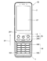
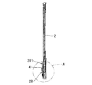
- FIG. 1 is a front view showing a slide type mobile phone according to an embodiment of the present invention.
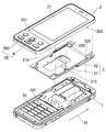
- FIG. 2 is an exploded perspective view of the slide type mobile phone.
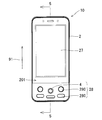
- FIG. 3 is a front view used for explaining the closed state of the device body of the slide type mobile phone.
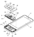
- FIG. 4 is an exploded perspective view of a second cabinet constituting the device main body.
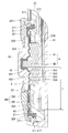
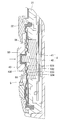
- FIG. 5 is a cross-sectional view of the second cabinet along line 5-5 shown in FIG.
- FIG. 6 is an enlarged view of a region A shown in FIG.
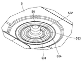
- FIG. 7 is an enlarged view showing a peripheral region including a bottomed cylindrical portion of the waterproof rubber provided in the slide type mobile phone.
- FIG. 1 is a front view showing a slide type mobile phone according to an embodiment of the present invention.
- FIG. 2 is an exploded perspective view of the slide type mobile phone.
- FIG. 3 is a front view used for explaining the closed state of the device body of the slide type mobile phone.
- FIG. 4 is an exploded perspective view of
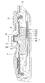
- FIG. 8 is a cross-sectional view used for explanation of a lever operation for sliding the lever portion upward of the lever switch provided in the slide type mobile phone.
- FIG. 9 is a cross-sectional view used for explanation of a lever operation for pushing the lever portion toward the switch body with respect to the lever switch provided in the slide type mobile phone.
- FIG. 1 is a front view showing a slide type mobile phone according to an embodiment of the present invention.
- the slide-type mobile phone includes a device body (10) configured by slidably connecting a first cabinet (1) and a second cabinet (2).
- a first operation section (18) constituted by a plurality of operation keys (180) to (180) is installed.
- a display unit composed of a liquid crystal display panel (27) is installed, while inside the second cabinet (2), there are a lever switch (4) and a plurality of switches.
- a second operation unit (28) composed of the operation keys (280) to (280) is provided.
- a part of the second operation unit (28), that is, the lever switch (4) is operated in a region different from the installation region of the liquid crystal display panel (27). The child (first key top (43) to be described later) and the operator (second key top (282) to be described later) of each operation key (280) are exposed.
- FIG. 2 is an exploded perspective view of the slide type mobile phone.
- a slide mechanism (3) is provided between the first cabinet (1) and the second cabinet (2) so as to be slidable.
- the slide mechanism (3) A slide body (31) and a slide defining portion (32) are included.
- the slide body (31) has an opposing surface on the second cabinet (2) side among the opposing surfaces of the first cabinet (1) and the second cabinet (2) (that is, the rear surface (202 of the second cabinet (2)). )).
- the slide defining portion (32) is a facing surface on the first cabinet (1) side (that is, the first cabinet (1)) among the facing surfaces of the first cabinet (1) and the second cabinet (2).
- the surface (101)) specifically, is fixed to an area different from the installation area of the first operating portion (18).
- the slide defining portion (32) is formed with a pair of left and right guide grooves (320) and (320) at both end positions, and the slide body (31) is formed in the pair of guide grooves (320) and (320).
- the left and right edges (310) and (310) are slidably engaged.
- the slide defining portion (32) defines the slide direction of the slide body (31) in the longitudinal direction (91) of the first cabinet (1).
- the device main body (10) of the slide type mobile phone moves both the first cabinet (1) and the second cabinet (2) relative to each other in the sliding direction, so that both cabinets (1) and (2) as shown in FIG. ) Is closed and the entire first operating section 18 is covered with the second cabinet 2, and both the cabinets 1, 2 are opened as shown in FIG. It is possible to change the state between the open state in which the entirety of) is exposed.
- the user of the slide type mobile phone uses the first operation unit (18) and the second operation unit (28) to slide. It is possible to operate a mobile phone. Further, even when the device main body (10) is set in the closed state as shown in FIG. 3, the user can operate the sliding mobile phone using the second operation unit (28). is there.
- FIG. 4 is an exploded perspective view of the second cabinet (2).
- 5 is a cross-sectional view of the second cabinet (2) taken along line 5-5 shown in FIG. 3, and
- FIG. 6 is an enlarged view of a region A shown in FIG.
- the lever switch (4) includes a rectangular parallelepiped switch body (41) and a lever portion (42) protruding from the switch body (41).
- the lever switch (4) of the present embodiment includes a lever operation that slides the lever portion (42) in a total of eight directions of four directions (up, down, left and right) and four oblique directions with respect to the switch body (41), and the switch body (41).
- the lever can be operated by pushing the lever part (42) toward.
- the lever switch (4) is mounted on a first board (61) provided inside the second cabinet (2).
- the second cabinet (2) includes a magnesium alloy chassis (21) and a cover member (22) joined to the chassis (21) to form a part of the surface (201) of the second cabinet (2). have.
- a rectangular opening (210) for accommodating the switch body (41) of the lever switch (4) is formed in an area covered by the cover member (22). Accordingly, the chassis (21) is used as a constituent member constituting the second cabinet (2), and also as an accommodating member provided with an opening (210) for accommodating the switch body (41) of the lever switch (4). It has been.
- the first board (61) is arranged on the rear side of the chassis (21), and the switch body (41) of the lever switch (4) mounted on the first board (61)
- the chassis (21) is inserted into the opening (210) from the rear side of the chassis (21).
- the switch body (41) is attached to the opening (210) of the chassis (21).
- the chassis (21) has a sheet-like second substrate (see FIG. 4) that extends in an area covered by the cover member (22) surrounding the opening (210) of the chassis (21). 62) is installed, and a dome switch (281) constituting each operation key (280) is mounted on the surface of the second substrate (62).
- the chassis (21) further includes a joining surface (211) to be expanded so as to surround the installation area of the second substrate (62) in an area covered by the cover member (22) and to which the cover member (22) is to be joined. Is formed.
- An annular groove (212) extending so as to surround the installation area of the second substrate (62) is recessed in the joint surface (211).
- a waterproof rubber (5) covering the opening (210) of the chassis (21) and the second substrate (62) is provided on the back side of the cover member (22).
- the waterproof rubber (5) is a waterproof elastic sheet.
- it may replace with a waterproof rubber (5) and may employ
- the waterproof rubber (5) has a shape that extends to a position where it overlaps the joint surface (211) of the chassis (21), and the outer edge (51) of the waterproof rubber (5) has an annular shape of the chassis (21).
- a seal portion (511) to be fitted into the groove (212) is provided so as to project toward the annular groove (212).
- the seal portion (511) of the waterproof rubber (5) is fitted into the annular groove (212) of the chassis (21) and the cover member. (22) is joined to the chassis (21), whereby the seal portion (511) is pressed into the annular groove (212) by the joining surface (220) of the cover member (22). Thereby, the seal portion (511) of the waterproof rubber (5) is fitted into the annular groove (212) without any gap.
- the outer edge portion (51) of the waterproof rubber (5) is interposed between the joint surfaces (211) (220) of the chassis (21) and the cover member (22).
- the waterproof rubber (5) is formed with a bottomed cylindrical portion (50) into which the tip of the lever portion (42) of the lever switch (4) is inserted.
- the bottomed cylindrical portion (50) opens to the back surface of the waterproof rubber (5) and protrudes from the surface of the waterproof rubber (5). Therefore, an operating force can be applied in various directions from the surface side of the waterproof rubber (5) to the bottomed cylindrical portion (50). Then, when an operating force is applied to the bottomed tubular portion (50), the lever portion (42) of the lever switch (4) moves in the operation direction together with the bottomed tubular portion (50). Therefore, it is possible to suppress the lever operation of the lever switch (4) from being hindered by the waterproof rubber (5).
- a protrusion (52) is formed in a region facing each dome switch (281).
- the protrusion (52) of the waterproof rubber (5) comes into contact with the dome switch (281).
- the corresponding dome switch (281) is connected via the protrusions (52). ) Is transmitted, and as a result, the dome switch (281) is pressed. Therefore, it is possible to suppress the pressing operation of the operation key (280) from being hindered by the waterproof rubber (5).
- a first key top (43) serving as an operator of the lever switch (4) is attached to the bottomed cylindrical portion (50) of the waterproof rubber (5).
- a fitting recess (431) is formed in the back part (430) of the first key top (43), and the bottomed tubular part (50) is fitted in the fitting recess (431).
- a second key top (282) serving as an operation key of the operation key (280) is adhered and fixed to the surface of the waterproof rubber (5) at a position overlapping with each projection (52) on the back side. .
- the cover member (22) includes a first window (221) for exposing the first key top (43) of the lever switch (4) to the surface of the cover member (22), and each operation key (280). And a second window (222) for exposing the second key top (282) to the surface of the cover member (22). Therefore, the user of the slide type mobile phone can execute the lever operation of the lever switch (4) by applying an operation force to the first key top (43), and each second key top (282). ), An operation of pressing the operation key (280) corresponding to the second key top (282) can be executed.
- FIG. 7 is an enlarged view showing a peripheral region of the waterproof rubber (5) including the bottomed cylindrical portion (50).
- the waterproof rubber (5) has a bottomed tubular portion by curving the waterproof rubber (5) around the bottomed tubular portion (50).
- a plurality of curved portions (531) to (534) are formed extending in an annular shape around (50) and surrounding the bottomed tubular portion (50).
- the waterproof rubber (5) has a first curved portion (531) curved in a dome shape from the bottomed cylindrical portion (50), and extends outward from the first curved portion (531) to be waterproof.
- a three-curved portion (533) and an annular fourth curved portion (534) extending outward from the third curved portion (533) and projecting to the back side of the waterproof rubber (5) are formed.
- the waterproof rubber (5) has a shape in which the area around the bottomed cylindrical portion (50) is undulated concentrically.
- the waterproof rubber (5) has a so-called bellows shape at least in the direction in which the lever portion (42) can be operated. Also, the length of the waterproof rubber (5) from the bottomed cylindrical part (50) to the outer edge part (51) is the same as the length of the waterproof rubber (5) being curved from the lever part (42). It is larger than the distance L to the joint surface (211) of the chassis (21). Here, the length dimension of the waterproof rubber (5) is set to be approximately the same as or larger than the width over which the lever portion (42) can slide.
- the waterproof rubber (5) has a shape in which the curved portions (531) to (534) are separated from the back portion (430) of the first key top (43).
- the water is waterproof rubber ( It is difficult to pass through 5). Accordingly, the infiltrated water stays on the surface of the waterproof rubber (5) or moves along the surface of the waterproof rubber (5).
- the outer edge portion (51) of the waterproof rubber (5) is interposed between the joint surfaces (211) (220) of the chassis (21) and the cover member (22), and the seal portion (511) is an annular groove. (212) is fitted with no gap.
- the slide type mobile phone has a waterproof structure that suppresses the intrusion of water on the surface of the second substrate (62) and the opening (210) that houses the lever switch (4).
- FIG. 6 the waterproof rubber (5) has a shape in which the area around the bottomed cylindrical portion (50) is undulated concentrically.
- an operating force is applied to the bottomed tubular portion (50) of the waterproof rubber (5) to slide the lever portion (42) of the lever switch (4) upward (the user is When the key top (43) is operated upward), as shown in FIG.
- the bottomed tubular portion (50) moves in the operation direction (upward), and accordingly the waterproof rubber (5)
- a compressive force is applied to the front region (54) existing in the moving direction of the bottomed cylindrical portion (50) to compress and compress the region (54), while the bottomed cylindrical portion (50)
- the rear region (55) existing in the direction opposite to the moving direction is applied with a tensile force for extending the region (55).
- the front region (54) and the rear region (55) of the waterproof rubber (5) are curved as shown in FIG. 6 even when no compressive force or tensile force is applied thereto. For this reason, the front region (54) of the waterproof rubber (5) is further curved only by applying a slight compressive force to the region (54), and therefore it is easily compressed. Further, the rear region (55) of the waterproof rubber (5) is stretched only by applying a slight tensile force to the region (55), and its curvature becomes small. Therefore, it is easily stretched. Even when an operation force is applied to the bottomed cylindrical portion (50) of the waterproof rubber (5) in the up / down / left / right and diagonal directions, the waterproof rubber (5) is deformed in the same manner as described above. Will do.
- the peripheral region (56) of the waterproof rubber (5) is curved as shown in FIG. 6 even when no compression force is applied thereto. For this reason, the peripheral region (56) of the waterproof rubber (5) is further curved only by applying a slight compressive force to the region (56), and is therefore easily compressed.
- the lever portion (42) receives a small repulsive force from the waterproof rubber (5) in the direction opposite to the operation direction. I just get it. Therefore, the lever operation of the lever switch (4) is not easily hindered by the waterproof rubber (5).
- the curved portions (531) to (534) of the waterproof rubber (5) have a shape surrounding the bottomed tubular portion (50). Therefore, the repulsive force that the lever portion (42) receives from the waterproof rubber (5) when the lever of the lever switch (4) is operated is very small.
- the bending portions (531) to (534) are unlikely to be hindered by the first key top (43) from being deformed to further increase the height. Therefore, the lever operation of the lever switch (4) is hardly hindered by the first key top (43) or the waterproof rubber (5).
- the configuration of each part of the present invention is not limited to the above embodiment, and various modifications can be made within the technical scope described in the claims.
- the shape of the waterproof rubber (5) shown in FIGS. 6 and 7 is an example, and the waterproof rubber (5) is curved around the bottomed tubular portion (50). Various shapes can be adopted. Further, the curved portions (531) to (534) formed in the waterproof sheet (5) are not limited to an annular shape, and have a polygonal shape according to the direction in which the lever operation of the lever portion (42) is possible. May be.
- the waterproof rubber (5) may adopt a shape in which the region between the bottomed tubular portion (50) and the outer edge portion (51) is loosened before assembly. .
- the bent portion is formed by bending the slack area of the waterproof rubber (5).
- the waterproof rubber (5) may be made of a highly stretchable material.
- the various configurations employed in the above-described slide type mobile phone can be applied to various mobile phones such as a foldable mobile phone and a straight type mobile phone.
- the various configurations employed in the slide type mobile phone are not limited to the mobile phone but can be applied to various electronic devices such as a PDA (Personal Digital Assistant), a digital camera, and a video camera.
- PDA Personal Digital Assistant
Landscapes
- Engineering & Computer Science (AREA)
- Signal Processing (AREA)
- Telephone Set Structure (AREA)
- Switches With Compound Operations (AREA)
- Switch Cases, Indication, And Locking (AREA)
Abstract
Disclosed is an electronic device wherein a waterproof structure is formed without hampering lever manipulation of a lever switch. The electronic device has a lever switch that is comprised of a switch body, and a lever section that enables lever manipulation in at least one direction. The device-body of the electronic device has formed on the surface thereof a window for exposing the lever section. The device body comprises a housing member that has formed thereon an opening for housing the switch body, and a cover member that is connected to the housing member and forms at least a portion of the surface of the device body. The window is formed on the cover member, is arranged at the back-face side of the cover member so as to cover the opening of the housing member, has a shape that broadens to a position where the connecting face of the housing member and the cover member overlaps thereto, and comprises an elastic sheet the outer edge of which intervenes in between the connection faces of the housing member and the cover member, and a closed-bottom cylinder-shaped section that protrudes from the surface of the elastic sheet and into which at least the front tip section of the lever section of the lever switch is inserted.
Description
本発明は、携帯電話機等、レバースイッチを具えた電子機器に関する。
The present invention relates to an electronic device having a lever switch such as a mobile phone.
この種の電子機器においては、機器本体の内部にレバースイッチが配備され、該レバースイッチは、スイッチ本体と、該スイッチ本体に対して多方向へのレバー操作が可能なレバー部とから構成されている。又、機器本体には、その表面にレバースイッチのレバー部を露出させる窓が形成されている(例えば、特許文献1参照)。
In this type of electronic device, a lever switch is provided inside the device main body, and the lever switch is composed of a switch main body and a lever portion that can operate a lever in multiple directions with respect to the switch main body. Yes. Further, a window for exposing the lever portion of the lever switch is formed on the surface of the device main body (see, for example, Patent Document 1).
ところで、近年、電子機器に防水構造を設けることが望まれている。防水構造として、機器本体に形成されている窓等の開口を、防水シートや防水ラバー等の防水部材によって覆った構成が考えられる。しかしながら、レバースイッチを具えた電子機器にこの構成を適用すると、レバー部が防水部材によって覆われ、その結果、レバースイッチのレバー操作が防水部材によって妨げられることになる。このため、従来は、レバースイッチを具えた電子機器に対して防水構造を設けることが困難であった。
Incidentally, in recent years, it has been desired to provide a waterproof structure for electronic devices. As a waterproof structure, a configuration in which an opening of a window or the like formed in the device main body is covered with a waterproof member such as a waterproof sheet or a waterproof rubber can be considered. However, when this configuration is applied to an electronic device having a lever switch, the lever portion is covered with the waterproof member, and as a result, the lever operation of the lever switch is hindered by the waterproof member. For this reason, conventionally, it has been difficult to provide a waterproof structure for an electronic device having a lever switch.
そこで本発明の目的は、レバースイッチによってレバー操作が妨げられることを抑制した防水構造が設けられた電子機器を提供することである。
Therefore, an object of the present invention is to provide an electronic device provided with a waterproof structure in which the lever operation is prevented from being hindered by a lever switch.
本発明に係る電子機器は、
機器本体と、
該機器本体の内部に配備されたレバースイッチと
を具え、
該レバースイッチは、
スイッチ本体と、
該スイッチ本体に対して少なくとも一方向へのレバー操作が可能なレバー部と、
から構成され、
前記機器本体には、その表面に前記レバースイッチのレバー部を露出させる窓が形成されている電子機器において、
前記機器本体は、
前記レバースイッチのスイッチ本体を収容する開口が設けられた収容部材と、
該収容部材に接合されて前記機器本体の表面の少なくとも一部を形成するカバー部材と、
を有し、
前記窓は、該カバー部材に形成され、
前記カバー部材の背面側に前記収容部材の開口を覆うよう配備され、前記収容部材とカバー部材との接合面と重なる位置まで拡がった形状を有し、外縁部が前記収容部材とカバー部材との接合面間に介在する弾性シートと、
前記弾性シートの表面から突出し、前記レバースイッチのレバー部の少なくとも先端部が挿入される有底筒状部と、
を有する。
尚、弾性シートには、防水性を有するシート状の弾性部材を用いることが出来る。 The electronic device according to the present invention is
The device body,
A lever switch arranged inside the device body,
The lever switch
The switch body,
A lever portion capable of lever operation in at least one direction with respect to the switch body;
Consisting of
In the electronic device in which the window for exposing the lever portion of the lever switch is formed on the surface of the device main body,
The device body is
A housing member provided with an opening for housing the switch body of the lever switch;
A cover member joined to the housing member to form at least a part of the surface of the device body;
Have
The window is formed in the cover member;
The rear surface of the cover member is disposed so as to cover the opening of the housing member, has a shape that extends to a position overlapping the joint surface between the housing member and the cover member, and an outer edge portion between the housing member and the cover member. An elastic sheet interposed between the joining surfaces;
A bottomed cylindrical portion that protrudes from the surface of the elastic sheet and into which at least the tip of the lever portion of the lever switch is inserted;
Have
A sheet-like elastic member having waterproofness can be used for the elastic sheet.
上記電子機器においては、カバー部材の窓からカバー部材の背面側へ水が浸入した場合でも、該水は弾性シートを通過し難い。従って、浸入した水は、弾性シートの表面に滞留し、或いは弾性シートの表面に沿って移動することになる。ここで、弾性シートの外縁部が収容部材とカバー部材との接合面間に介在している。従って、浸入した水が弾性シートの表面上を接合面の方へ向けて移動した場合でも、該水が弾性シートの背面へ回り込むことが、弾性シートの外縁部によって抑制されることになる。又、収容部材とカバー部材との接合面間を通じて機器本体の外部から内部へ水が浸入することが、該接合面間に介在した弾性シートの外縁部によって防止されることになる。よって、レバースイッチを収容する開口内には、機器本体の外部の水の浸入を防ぐことができる。即ち、上記電子機器は、レバースイッチを収容する開口内への水の浸入を防止する防水構造を有することになる。
In the above electronic device, even when water enters from the window of the cover member to the back side of the cover member, the water hardly passes through the elastic sheet. Therefore, the infiltrated water stays on the surface of the elastic sheet or moves along the surface of the elastic sheet. Here, the outer edge part of the elastic sheet is interposed between the joint surfaces of the housing member and the cover member. Therefore, even when the infiltrated water moves toward the joining surface on the surface of the elastic sheet, the outer edge portion of the elastic sheet prevents the water from entering the back surface of the elastic sheet. In addition, it is possible to prevent water from entering the inside of the apparatus main body through the space between the joint surfaces of the housing member and the cover member by the outer edge portion of the elastic sheet interposed between the joint surfaces. Therefore, intrusion of water outside the device main body can be prevented in the opening that accommodates the lever switch. That is, the electronic device has a waterproof structure that prevents water from entering the opening that houses the lever switch.
更に、上記電子機器においては、有底筒状部が弾性シートの表面から突出しているので、該弾性シートの表面側から有底筒状部に対して、様々な方向へ操作力を加えることが出来る。そして、有底筒状部に操作力が加えられることにより、レバースイッチのレバー部が有底筒状部と共に操作方向へ移動することになる。よって、レバースイッチのレバー操作が弾性シートによって妨げられることを抑制できる。
Furthermore, in the electronic device, since the bottomed cylindrical portion protrudes from the surface of the elastic sheet, an operating force can be applied in various directions to the bottomed cylindrical portion from the surface side of the elastic sheet. I can do it. Then, when an operating force is applied to the bottomed cylindrical portion, the lever portion of the lever switch moves in the operation direction together with the bottomed cylindrical portion. Therefore, it can suppress that the lever operation of a lever switch is prevented by an elastic sheet.
本発明に係る電子機器によれば、レバースイッチによってレバー操作が妨げられることを抑制することができる。
The electronic device according to the present invention can prevent the lever operation from being hindered by the lever switch.
以下、本発明をスライド式携帯電話機に実施した形態につき、図面に沿って具体的に説明する。
図1は、本発明の一実施形態に係るスライド式携帯電話機を示す正面図である。図1に示す様に、スライド式携帯電話機は、第1キャビネット(1)と第2キャビネット(2)とを互いにスライド可能に連結して構成された機器本体(10)を具えている。第1キャビネット(1)の表面(101)には、複数の操作キー(180)~(180)によって構成された第1操作部(18)が設置されている。 Hereinafter, the embodiment in which the present invention is applied to a slide-type mobile phone will be described in detail with reference to the drawings.
FIG. 1 is a front view showing a slide type mobile phone according to an embodiment of the present invention. As shown in FIG. 1, the slide-type mobile phone includes a device body (10) configured by slidably connecting a first cabinet (1) and a second cabinet (2). On the surface (101) of the first cabinet (1), a first operation section (18) constituted by a plurality of operation keys (180) to (180) is installed.
第2キャビネット(2)の表面(201)には、液晶表示パネル(27)によって構成された表示部が設置される一方、第2キャビネット(2)の内部には、レバースイッチ(4)と複数の操作キー(280)~(280)とから構成された第2操作部(28)が配備されている。そして、第2キャビネット(2)の表面(201)には、液晶表示パネル(27)の設置領域とは異なる領域に、第2操作部(28)の一部、即ちレバースイッチ(4)の操作子(後述する第1キートップ(43))と各操作キー(280)の操作子(後述する第2キートップ(282))とが露出している。
On the surface (201) of the second cabinet (2), a display unit composed of a liquid crystal display panel (27) is installed, while inside the second cabinet (2), there are a lever switch (4) and a plurality of switches. A second operation unit (28) composed of the operation keys (280) to (280) is provided. On the surface (201) of the second cabinet (2), a part of the second operation unit (28), that is, the lever switch (4) is operated in a region different from the installation region of the liquid crystal display panel (27). The child (first key top (43) to be described later) and the operator (second key top (282) to be described later) of each operation key (280) are exposed.
図2は、スライド式携帯電話機の分解斜視図である。図2に示す様に、第1キャビネット(1)と第2キャビネット(2)との間には、これらをスライド可能に連結するスライド機構(3)が設けられ、該スライド機構(3)は、スライド体(31)とスライド規定部(32)とから構成されている。スライド体(31)は、第1キャビネット(1)と第2キャビネット(2)との対向面の内、第2キャビネット(2)側の対向面(即ち、第2キャビネット(2)の背面(202))に固定される。一方、スライド規定部(32)は、第1キャビネット(1)と第2キャビネット(2)との対向面の内、第1キャビネット(1)側の対向面(即ち、第1キャビネット(1)の表面(101))、具体的には第1操作部(18)の設置領域とは異なる領域に固定される。
FIG. 2 is an exploded perspective view of the slide type mobile phone. As shown in FIG. 2, a slide mechanism (3) is provided between the first cabinet (1) and the second cabinet (2) so as to be slidable. The slide mechanism (3) A slide body (31) and a slide defining portion (32) are included. The slide body (31) has an opposing surface on the second cabinet (2) side among the opposing surfaces of the first cabinet (1) and the second cabinet (2) (that is, the rear surface (202 of the second cabinet (2)). )). On the other hand, the slide defining portion (32) is a facing surface on the first cabinet (1) side (that is, the first cabinet (1)) among the facing surfaces of the first cabinet (1) and the second cabinet (2). The surface (101)), specifically, is fixed to an area different from the installation area of the first operating portion (18).
又、スライド規定部(32)には、その両端位置に左右一対のガイド溝(320)(320)が形成されており、該一対のガイド溝(320)(320)に、スライド体(31)の左右の縁部(310)(310)が摺動自在に係合している。斯くして、スライド規定部(32)は、スライド体(31)のスライド方向を第1キャビネット(1)の長手方向(91)に規定している。
The slide defining portion (32) is formed with a pair of left and right guide grooves (320) and (320) at both end positions, and the slide body (31) is formed in the pair of guide grooves (320) and (320). The left and right edges (310) and (310) are slidably engaged. Thus, the slide defining portion (32) defines the slide direction of the slide body (31) in the longitudinal direction (91) of the first cabinet (1).
よって、上記スライド式携帯電話機の機器本体(10)は、第1キャビネット(1)と第2キャビネット(2)をスライド方向に相対移動させることにより、図3に示す如く両キャビネット(1)(2)が閉じて第1操作部(18)の全体が第2キャビネット(2)によって被覆された閉じ状態と、図1に示す如く両キャビネット(1)(2)が開いて第1操作部(18)の全体が露出した開き状態との間で状態を変更させることが可能である。
Therefore, the device main body (10) of the slide type mobile phone moves both the first cabinet (1) and the second cabinet (2) relative to each other in the sliding direction, so that both cabinets (1) and (2) as shown in FIG. ) Is closed and the entire first operating section 18 is covered with the second cabinet 2, and both the cabinets 1, 2 are opened as shown in FIG. It is possible to change the state between the open state in which the entirety of) is exposed.
上記スライド式携帯電話機のユーザは、図1に示す如く機器本体(10)が開き状態に設定されている場合、第1操作部(18)と第2操作部(28)とを用いてスライド式携帯電話機を操作することが可能である。又、図3に示す如く機器本体(10)が閉じ状態に設定されている場合であっても、ユーザは、第2操作部(28)を用いてスライド式携帯電話機を操作することが可能である。
When the device main body (10) is set to the open state as shown in FIG. 1, the user of the slide type mobile phone uses the first operation unit (18) and the second operation unit (28) to slide. It is possible to operate a mobile phone. Further, even when the device main body (10) is set in the closed state as shown in FIG. 3, the user can operate the sliding mobile phone using the second operation unit (28). is there.
図4は、第2キャビネット(2)の分解斜視図である。又、図5は、図3に示される5-5線に沿う第2キャビネット(2)の断面図であり、図6は、図5に示されるA領域の拡大図である。図4及び図6に示す様に、レバースイッチ(4)は、直方体状のスイッチ本体(41)と、該スイッチ本体(41)に突設されたレバー部(42)とを具えている。本実施形態のレバースイッチ(4)は、スイッチ本体(41)に対して上下左右の4方向と斜め4方向の計8方向へレバー部(42)をスライドさせるレバー操作と、スイッチ本体(41)へ向けてレバー部(42)を押し込むレバー操作とが可能である。又、レバースイッチ(4)は、第2キャビネット(2)の内部に配備された第1基板(61)に搭載されている。
FIG. 4 is an exploded perspective view of the second cabinet (2). 5 is a cross-sectional view of the second cabinet (2) taken along line 5-5 shown in FIG. 3, and FIG. 6 is an enlarged view of a region A shown in FIG. As shown in FIGS. 4 and 6, the lever switch (4) includes a rectangular parallelepiped switch body (41) and a lever portion (42) protruding from the switch body (41). The lever switch (4) of the present embodiment includes a lever operation that slides the lever portion (42) in a total of eight directions of four directions (up, down, left and right) and four oblique directions with respect to the switch body (41), and the switch body (41). The lever can be operated by pushing the lever part (42) toward. The lever switch (4) is mounted on a first board (61) provided inside the second cabinet (2).
第2キャビネット(2)は、マグネシウム合金製のシャーシ(21)と、該シャーシ(21)に接合されて第2キャビネット(2)の表面(201)の一部を形成するカバー部材(22)とを有している。シャーシ(21)には、カバー部材(22)によって覆われる領域に、レバースイッチ(4)のスイッチ本体(41)を収容する四角形の開口(210)が形成されている。従って、シャーシ(21)は、第2キャビネット(2)を構成する構成部材として用いられると共に、レバースイッチ(4)のスイッチ本体(41)を収容する開口(210)が設けられた収容部材として用いられている。
The second cabinet (2) includes a magnesium alloy chassis (21) and a cover member (22) joined to the chassis (21) to form a part of the surface (201) of the second cabinet (2). have. In the chassis (21), a rectangular opening (210) for accommodating the switch body (41) of the lever switch (4) is formed in an area covered by the cover member (22). Accordingly, the chassis (21) is used as a constituent member constituting the second cabinet (2), and also as an accommodating member provided with an opening (210) for accommodating the switch body (41) of the lever switch (4). It has been.
図6に示す様に、第1基板(61)は、シャーシ(21)の背面側に配置され、第1基板(61)に搭載されているレバースイッチ(4)のスイッチ本体(41)は、シャーシ(21)の開口(210)に、シャーシ(21)の背面側から挿入されている。そして、スイッチ本体(41)は、シャーシ(21)の開口(210)に取り付けられている。
As shown in FIG. 6, the first board (61) is arranged on the rear side of the chassis (21), and the switch body (41) of the lever switch (4) mounted on the first board (61) The chassis (21) is inserted into the opening (210) from the rear side of the chassis (21). The switch body (41) is attached to the opening (210) of the chassis (21).
図4及び図6に示す様に、シャーシ(21)には、カバー部材(22)によって覆われる領域に、シャーシ(21)の開口(210)を包囲して拡がったシート状の第2基板(62)が設置されており、該第2基板(62)の表面には、各操作キー(280)を構成するドームスイッチ(281)が搭載されている。
As shown in FIGS. 4 and 6, the chassis (21) has a sheet-like second substrate (see FIG. 4) that extends in an area covered by the cover member (22) surrounding the opening (210) of the chassis (21). 62) is installed, and a dome switch (281) constituting each operation key (280) is mounted on the surface of the second substrate (62).
シャーシ(21)には更に、カバー部材(22)によって覆われる領域に、第2基板(62)の設置領域を包囲して拡がると共にカバー部材(22)が接合されるべき接合面(211)が形成されている。該接合面(211)には、第2基板(62)の設置領域を包囲して延びた環状溝(212)が凹設されている。
The chassis (21) further includes a joining surface (211) to be expanded so as to surround the installation area of the second substrate (62) in an area covered by the cover member (22) and to which the cover member (22) is to be joined. Is formed. An annular groove (212) extending so as to surround the installation area of the second substrate (62) is recessed in the joint surface (211).
図4及び図6に示す様に、カバー部材(22)の背面側には、シャーシ(21)の開口(210)及び第2基板(62)を覆う防水ラバー(5)が配備されている。ここで、該防水ラバー(5)は、防水性を有する弾性シートである。尚、防水ラバー(5)に替えて、防水性を有する種々の弾性シートを採用してもよい。
As shown in FIGS. 4 and 6, a waterproof rubber (5) covering the opening (210) of the chassis (21) and the second substrate (62) is provided on the back side of the cover member (22). Here, the waterproof rubber (5) is a waterproof elastic sheet. In addition, it may replace with a waterproof rubber (5) and may employ | adopt various elastic sheets which have waterproofness.
防水ラバー(5)は、シャーシ(21)の接合面(211)と重なる位置まで拡がった形状を有しており、防水ラバー(5)の外縁部(51)には、シャーシ(21)の環状溝(212)に嵌合すべきシール部(511)が、環状溝(212)の方へ向けて突設されている。
The waterproof rubber (5) has a shape that extends to a position where it overlaps the joint surface (211) of the chassis (21), and the outer edge (51) of the waterproof rubber (5) has an annular shape of the chassis (21). A seal portion (511) to be fitted into the groove (212) is provided so as to project toward the annular groove (212).
従って、図6に示す様に第2キャビネット(2)の組み立て状態においては、防水ラバー(5)のシール部(511)がシャーシ(21)の環状溝(212)に嵌合すると共に、カバー部材(22)がシャーシ(21)に接合され、これにより、カバー部材(22)の接合面(220)によってシール部(511)が環状溝(212)内へ押圧されることになる。これにより、防水ラバー(5)のシール部(511)は、環状溝(212)内に隙間なく嵌合されることになる。又、このとき、防水ラバー(5)の外縁部(51)は、シャーシ(21)とカバー部材(22)との接合面(211)(220)間に介在することになる。
Therefore, as shown in FIG. 6, in the assembled state of the second cabinet (2), the seal portion (511) of the waterproof rubber (5) is fitted into the annular groove (212) of the chassis (21) and the cover member. (22) is joined to the chassis (21), whereby the seal portion (511) is pressed into the annular groove (212) by the joining surface (220) of the cover member (22). Thereby, the seal portion (511) of the waterproof rubber (5) is fitted into the annular groove (212) without any gap. At this time, the outer edge portion (51) of the waterproof rubber (5) is interposed between the joint surfaces (211) (220) of the chassis (21) and the cover member (22).
更に、防水ラバー(5)には、レバースイッチ(4)のレバー部(42)の先端部が挿入される有底筒状部(50)が形成されている。ここで、有底筒状部(50)は、防水ラバー(5)の背面に開口すると共に、防水ラバー(5)の表面から突出している。従って、防水ラバー(5)の表面側から有底筒状部(50)に対して、様々な方向へ操作力を加えることが出来る。そして、有底筒状部(50)に操作力が加えられることにより、レバースイッチ(4)のレバー部(42)が有底筒状部(50)と共に操作方向へ移動することになる。よって、レバースイッチ(4)のレバー操作が、防水ラバー(5)によって妨げられることを抑制できる。
Further, the waterproof rubber (5) is formed with a bottomed cylindrical portion (50) into which the tip of the lever portion (42) of the lever switch (4) is inserted. Here, the bottomed cylindrical portion (50) opens to the back surface of the waterproof rubber (5) and protrudes from the surface of the waterproof rubber (5). Therefore, an operating force can be applied in various directions from the surface side of the waterproof rubber (5) to the bottomed cylindrical portion (50). Then, when an operating force is applied to the bottomed tubular portion (50), the lever portion (42) of the lever switch (4) moves in the operation direction together with the bottomed tubular portion (50). Therefore, it is possible to suppress the lever operation of the lever switch (4) from being hindered by the waterproof rubber (5).
又、防水ラバー(5)の背面には、各ドームスイッチ(281)と対向することとなる領域に突起部(52)が形成されている。図6に示す様に第2キャビネット(2)の組み立て状態においては、防水ラバー(5)の突起部(52)は、ドームスイッチ(281)に当接することになる。そして、防水ラバー(5)の表面の内、背面側の各突起部(52)と重なる領域に押圧力が加えられることにより、該突起部(52)を介してこれに対応するドームスイッチ(281)に押圧力が伝わり、その結果、ドームスイッチ(281)が押圧されることになる。よって、操作キー(280)の押圧操作が、防水ラバー(5)によって妨げられることを抑制できる。
In addition, on the back surface of the waterproof rubber (5), a protrusion (52) is formed in a region facing each dome switch (281). As shown in FIG. 6, in the assembled state of the second cabinet (2), the protrusion (52) of the waterproof rubber (5) comes into contact with the dome switch (281). Then, when a pressing force is applied to a region of the surface of the waterproof rubber (5) that overlaps with the protrusions (52) on the back side, the corresponding dome switch (281) is connected via the protrusions (52). ) Is transmitted, and as a result, the dome switch (281) is pressed. Therefore, it is possible to suppress the pressing operation of the operation key (280) from being hindered by the waterproof rubber (5).
防水ラバー(5)の有底筒状部(50)には、レバースイッチ(4)の操作子となる第1キートップ(43)が取り付けられている。具体的には、第1キートップ(43)の背部(430)には、嵌合凹部(431)が形成されており、該嵌合凹部(431)に有底筒状部(50)が嵌合されている。又、防水ラバー(5)の表面には、背面側の各突起部(52)と重なる位置に、操作キー(280)の操作子となる第2キートップ(282)が貼着固定されている。
A first key top (43) serving as an operator of the lever switch (4) is attached to the bottomed cylindrical portion (50) of the waterproof rubber (5). Specifically, a fitting recess (431) is formed in the back part (430) of the first key top (43), and the bottomed tubular part (50) is fitted in the fitting recess (431). Are combined. Further, a second key top (282) serving as an operation key of the operation key (280) is adhered and fixed to the surface of the waterproof rubber (5) at a position overlapping with each projection (52) on the back side. .
ここで、カバー部材(22)には、レバースイッチ(4)の第1キートップ(43)をカバー部材(22)の表面に露出させる第1の窓(221)と、各操作キー(280)の第2キートップ(282)をカバー部材(22)の表面に露出させる第2の窓(222)とが形成されている。従って、上記スライド式携帯電話機のユーザは、第1キートップ(43)に操作力を加えることにより、レバースイッチ(4)のレバー操作を実行することが出来、又、各第2キートップ(282)に操作力を加えることにより、該第2キートップ(282)に対応する操作キー(280)の押圧操作を実行することが出来る。
Here, the cover member (22) includes a first window (221) for exposing the first key top (43) of the lever switch (4) to the surface of the cover member (22), and each operation key (280). And a second window (222) for exposing the second key top (282) to the surface of the cover member (22). Therefore, the user of the slide type mobile phone can execute the lever operation of the lever switch (4) by applying an operation force to the first key top (43), and each second key top (282). ), An operation of pressing the operation key (280) corresponding to the second key top (282) can be executed.
図7は、防水ラバー(5)について、有底筒状部(50)を含むその周辺領域を示した拡大図である。図7に示す様に(図6も参照)、防水ラバー(5)には、該防水ラバー(5)を有底筒状部(50)の周囲にて湾曲させることにより、有底筒状部(50)の周りを円環状に延びて該有底筒状部(50)を包囲した複数の湾曲部(531)~(534)が形成されている。
FIG. 7 is an enlarged view showing a peripheral region of the waterproof rubber (5) including the bottomed cylindrical portion (50). As shown in FIG. 7 (see also FIG. 6), the waterproof rubber (5) has a bottomed tubular portion by curving the waterproof rubber (5) around the bottomed tubular portion (50). A plurality of curved portions (531) to (534) are formed extending in an annular shape around (50) and surrounding the bottomed tubular portion (50).
具体的には、防水ラバー(5)には、有底筒状部(50)からドーム状に湾曲した第1湾曲部(531)と、該第1湾曲部(531)から外側へ拡がって防水ラバー(5)の背面側へ隆起した円環状の第2湾曲部(532)と、該第2湾曲部(532)から外側へ拡がって防水ラバー(5)の表面側へ隆起した円環状の第3湾曲部(533)と、該第3湾曲部(533)から外側へ拡がって防水ラバー(5)の背面側へ隆起した円環状の第4湾曲部(534)とが形成されている。斯くして、防水ラバー(5)は、有底筒状部(50)の周囲の領域が同心円状に波打った形状を有している。
Specifically, the waterproof rubber (5) has a first curved portion (531) curved in a dome shape from the bottomed cylindrical portion (50), and extends outward from the first curved portion (531) to be waterproof. An annular second curved portion (532) raised to the back side of the rubber (5), and an annular second curved portion extending outward from the second curved portion (532) and raised to the surface side of the waterproof rubber (5) A three-curved portion (533) and an annular fourth curved portion (534) extending outward from the third curved portion (533) and projecting to the back side of the waterproof rubber (5) are formed. Thus, the waterproof rubber (5) has a shape in which the area around the bottomed cylindrical portion (50) is undulated concentrically.
従って、図6に示す様に、少なくともレバー部(42)のレバー操作が可能な方向において、防水ラバー(5)は、所謂、蛇腹形状を有している。又、防水ラバー(5)の有底筒状部(50)から外縁部(51)までの長さ寸法が、防水ラバー(5)が湾曲している長さ分だけ、レバー部(42)からシャーシ(21)の接合面(211)までの距離Lよりも大きくなっている。ここで、防水ラバー(5)の前記長さ寸法は、レバー部(42)がスライド可能な幅と同程度か、若しくはそれより大きく設定されている。
Therefore, as shown in FIG. 6, the waterproof rubber (5) has a so-called bellows shape at least in the direction in which the lever portion (42) can be operated. Also, the length of the waterproof rubber (5) from the bottomed cylindrical part (50) to the outer edge part (51) is the same as the length of the waterproof rubber (5) being curved from the lever part (42). It is larger than the distance L to the joint surface (211) of the chassis (21). Here, the length dimension of the waterproof rubber (5) is set to be approximately the same as or larger than the width over which the lever portion (42) can slide.
更に、防水ラバー(5)は、図6に示す様に、その湾曲部(531)~(534)が第1キートップ(43)の背部(430)から離間した形状を有している。
Furthermore, as shown in FIG. 6, the waterproof rubber (5) has a shape in which the curved portions (531) to (534) are separated from the back portion (430) of the first key top (43).
上記スライド式携帯電話機においては、カバー部材(22)の第1及び第2の窓(221)(222)からカバー部材(22)の背面側へ水が浸入した場合でも、該水は防水ラバー(5)を通過し難い。従って、浸入した水は、防水ラバー(5)の表面に滞留し、或いは防水ラバー(5)の表面に沿って移動することになる。ここで、防水ラバー(5)の外縁部(51)がシャーシ(21)とカバー部材(22)との接合面(211)(220)間に介在し、又、シール部(511)が環状溝(212)に隙間なく嵌合されている。従って、浸入した水が防水ラバー(5)の表面上を接合面(211)(220)の方へ向けて移動した場合でも、該水が防水ラバー(5)の背面へ回り込むことが、防水ラバー(5)の外縁部(51)とシール部(511)とによって抑制されることになる。
In the above-described sliding type mobile phone, even when water enters the back side of the cover member (22) from the first and second windows (221) and (222) of the cover member (22), the water is waterproof rubber ( It is difficult to pass through 5). Accordingly, the infiltrated water stays on the surface of the waterproof rubber (5) or moves along the surface of the waterproof rubber (5). Here, the outer edge portion (51) of the waterproof rubber (5) is interposed between the joint surfaces (211) (220) of the chassis (21) and the cover member (22), and the seal portion (511) is an annular groove. (212) is fitted with no gap. Therefore, even if the invaded water moves on the surface of the waterproof rubber (5) toward the joint surfaces (211) (220), the water may wrap around to the back of the waterproof rubber (5). It is suppressed by the outer edge part (51) and the seal part (511) of (5).
又、シャーシ(21)とカバー部材(22)との接合面(211)(220)間を通じて機器本体(10)の外部から内部へ水が浸入することが、該接合面(211)(220)間に介在した防水ラバー(5)の外縁部(51)と、環状溝(212)に隙間なく嵌合されたシール部(511)とによって抑制されることになる。
In addition, it is possible for water to enter from the outside of the device main body (10) through the space between the joint surfaces (211) and (220) of the chassis (21) and the cover member (22), the joint surfaces (211) (220) It is restrained by the outer edge portion (51) of the waterproof rubber (5) interposed therebetween and the seal portion (511) fitted into the annular groove (212) without any gap.
よって、第2基板(62)の表面上、及びレバースイッチ(4)を収容する開口(210)内には、機器本体(10)の外部の水が浸入し難い。即ち、上記スライド式携帯電話機は、第2基板(62)の表面上、及びレバースイッチ(4)を収容する開口(210)内への水の浸入を抑制する防水構造を有することになる。
Therefore, it is difficult for water outside the device body (10) to enter the surface of the second substrate (62) and the opening (210) for accommodating the lever switch (4). That is, the slide type mobile phone has a waterproof structure that suppresses the intrusion of water on the surface of the second substrate (62) and the opening (210) that houses the lever switch (4).
上記スライド式携帯電話機においては、防水ラバー(5)の有底筒状部(50)に操作力が加えられていない場合(ユーザが第1キートップ(43)を操作していない場合)、図6に示す様に、防水ラバー(5)は、有底筒状部(50)の周囲の領域が同心円状に波打った形状を有している。一方、レバースイッチ(4)のレバー部(42)を上方へスライドさせるべく、防水ラバー(5)の有底筒状部(50)に対して上方へ操作力が加えられた場合(ユーザが第1キートップ(43)を上方へ操作した場合)、図8に示す様に、操作方向(上方)へ有底筒状部(50)が移動し、これに伴って防水ラバー(5)には、有底筒状部(50)の移動方向に存在する前方領域(54)に、該領域(54)を押し縮めようとする圧縮力が付与される一方、有底筒状部(50)の移動方向とは反対方向に存在する後方領域(55)に、該領域(55)を引き伸ばそうとする引張力が付与されることになる。
In the above slide type mobile phone, when the operating force is not applied to the bottomed cylindrical portion (50) of the waterproof rubber (5) (when the user does not operate the first key top (43)), FIG. As shown in FIG. 6, the waterproof rubber (5) has a shape in which the area around the bottomed cylindrical portion (50) is undulated concentrically. On the other hand, when an operating force is applied to the bottomed tubular portion (50) of the waterproof rubber (5) to slide the lever portion (42) of the lever switch (4) upward (the user is When the key top (43) is operated upward), as shown in FIG. 8, the bottomed tubular portion (50) moves in the operation direction (upward), and accordingly the waterproof rubber (5) A compressive force is applied to the front region (54) existing in the moving direction of the bottomed cylindrical portion (50) to compress and compress the region (54), while the bottomed cylindrical portion (50) The rear region (55) existing in the direction opposite to the moving direction is applied with a tensile force for extending the region (55).
ここで、防水ラバー(5)の前方領域(54)及び後方領域(55)は、これらに圧縮力又は引張力が付与されていないときであっても、図6に示す如く湾曲している。このため、防水ラバー(5)の前方領域(54)は、この領域(54)に僅かな圧縮力が付与されただけで更に湾曲し、従って容易に押し縮められることになる。又、防水ラバー(5)の後方領域(55)は、この領域(55)に僅かな引張力が付与されるだけで伸びてその湾曲が小さくなり、従って容易に引き伸ばされることになる。防水ラバー(5)の有底筒状部(50)に対して、上下左右、斜めの各方向へ操作力が加えられた場合においても、防水ラバー(5)は、上述したのと同様に変形することになる。
Here, the front region (54) and the rear region (55) of the waterproof rubber (5) are curved as shown in FIG. 6 even when no compressive force or tensile force is applied thereto. For this reason, the front region (54) of the waterproof rubber (5) is further curved only by applying a slight compressive force to the region (54), and therefore it is easily compressed. Further, the rear region (55) of the waterproof rubber (5) is stretched only by applying a slight tensile force to the region (55), and its curvature becomes small. Therefore, it is easily stretched. Even when an operation force is applied to the bottomed cylindrical portion (50) of the waterproof rubber (5) in the up / down / left / right and diagonal directions, the waterproof rubber (5) is deformed in the same manner as described above. Will do.
又、レバースイッチ(4)のレバー部(42)をスイッチ本体(41)へ向けて押し込むべく、防水ラバー(5)の有底筒状部(50)に押圧力が加えられた場合(ユーザが第1キートップ(43)を押圧した場合)、図9に示す様に、押圧方向へ有底筒状部(50)が移動し、これに伴って防水ラバー(5)には、有底筒状部(50)の周りに存在する周辺領域(56)に、該領域(56)を外側へ押し縮めようとする圧縮力が付与されることになる。
In addition, when pressing force is applied to the bottomed cylindrical part (50) of the waterproof rubber (5) to push the lever part (42) of the lever switch (4) toward the switch body (41) (the user When the first key top (43) is pressed), as shown in FIG. 9, the bottomed cylindrical portion (50) moves in the pressing direction, and accordingly the waterproof rubber (5) has a bottomed cylinder. A compressive force for compressing the region (56) outward is applied to the peripheral region (56) existing around the shape portion (50).
ここで、防水ラバー(5)の周辺領域(56)は、これに圧縮力が付与されていないときであっても、図6に示す如く湾曲している。このため、防水ラバー(5)の周辺領域(56)は、この領域(56)に僅かな圧縮力が付与されただけで更に湾曲し、従って容易に押し縮められることになる。
Here, the peripheral region (56) of the waterproof rubber (5) is curved as shown in FIG. 6 even when no compression force is applied thereto. For this reason, the peripheral region (56) of the waterproof rubber (5) is further curved only by applying a slight compressive force to the region (56), and is therefore easily compressed.
よって、上記スライド式携帯電話機によれば、レバースイッチ(4)のレバー操作時であっても、レバー部(42)は、防水ラバー(5)から、操作方向とは反対方向へ小さな反発力を受けるに過ぎない。従って、レバースイッチ(4)のレバー操作が防水ラバー(5)によって妨げられ難い。
Therefore, according to the slide type mobile phone, even when the lever of the lever switch (4) is operated, the lever portion (42) receives a small repulsive force from the waterproof rubber (5) in the direction opposite to the operation direction. I just get it. Therefore, the lever operation of the lever switch (4) is not easily hindered by the waterproof rubber (5).
上記スライド式携帯電話機においては、防水ラバー(5)の湾曲部(531)~(534)は、有底筒状部(50)を包囲した形状を有している。従って、レバースイッチ(4)のレバー操作時においてレバー部(42)が防水ラバー(5)から受ける反発力は、非常に小さくなっている。
In the slide type mobile phone, the curved portions (531) to (534) of the waterproof rubber (5) have a shape surrounding the bottomed tubular portion (50). Therefore, the repulsive force that the lever portion (42) receives from the waterproof rubber (5) when the lever of the lever switch (4) is operated is very small.
上記スライド式携帯電話機において湾曲部(531)~(534)が押し縮められたとき、これらの高さ寸法が大きくなる。ここで、湾曲部(531)~(534)が第1キートップ(43)の背部(430)に接触していると、湾曲部(531)~(534)は、その高さ寸法を更に大きくする変形が第1キートップ(43)によって妨げられることになる。これに対し、本実施形態のスライド式携帯電話機においては、図6に示す如く湾曲部(531)~(534)が第1キートップ(43)の背部(430)から離間して設けられている。従って、図8及び図9に示す様に、湾曲部(531)~(534)は、その高さ寸法を更に大きくする変形が第1キートップ(43)によって妨げられ難い。従って、レバースイッチ(4)のレバー操作が第1キートップ(43)又は防水ラバー(5)によって妨げられ難い。
¡When the curved portions (531) to (534) are compressed in the slide type mobile phone, these height dimensions become large. Here, when the curved portions (531) to (534) are in contact with the back portion (430) of the first key top (43), the curved portions (531) to (534) are further increased in height. The deformation to be prevented is prevented by the first key top (43). On the other hand, in the slide type mobile phone of the present embodiment, as shown in FIG. 6, the curved portions (531) to (534) are provided apart from the back portion (430) of the first key top (43). . Therefore, as shown in FIGS. 8 and 9, the bending portions (531) to (534) are unlikely to be hindered by the first key top (43) from being deformed to further increase the height. Therefore, the lever operation of the lever switch (4) is hardly hindered by the first key top (43) or the waterproof rubber (5).
尚、本発明の各部構成は上記実施の形態に限らず、請求の範囲に記載の技術的範囲内で種々の変形が可能である。図6及び図7に示す上記防水ラバー(5)の形状は一例であり、防水ラバー(5)には、該防水ラバー(5)を有底筒状部(50)の周囲にて湾曲させた様々な形状を採用することが出来る。又、防水シート(5)に形成されている湾曲部(531)~(534)は、円環状に限らず、レバー部(42)のレバー操作が可能な方向に応じて多角形状を有していてもよい。
The configuration of each part of the present invention is not limited to the above embodiment, and various modifications can be made within the technical scope described in the claims. The shape of the waterproof rubber (5) shown in FIGS. 6 and 7 is an example, and the waterproof rubber (5) is curved around the bottomed tubular portion (50). Various shapes can be adopted. Further, the curved portions (531) to (534) formed in the waterproof sheet (5) are not limited to an annular shape, and have a polygonal shape according to the direction in which the lever operation of the lever portion (42) is possible. May be.
更に、本発明において、防水ラバー(5)には、組み立て前の状態において有底筒状部(50)と外縁部(51)との間の領域が弛むこととなる形状を採用してもよい。この場合、防水ラバー(5)をシャーシ(21)に取り付ける際に、防水ラバー(5)の弛んだ領域を撓曲させることにより、上述した湾曲部が形成されることになる。又、防水ラバー(5)には、伸縮性の高い材質から形成されたものを採用してもよい。
Furthermore, in the present invention, the waterproof rubber (5) may adopt a shape in which the region between the bottomed tubular portion (50) and the outer edge portion (51) is loosened before assembly. . In this case, when the waterproof rubber (5) is attached to the chassis (21), the bent portion is formed by bending the slack area of the waterproof rubber (5). The waterproof rubber (5) may be made of a highly stretchable material.
上記スライド式携帯電話機に採用した各種構成は、折り畳み式携帯電話機、ストレートタイプの携帯電話機等、様々な携帯電話機に適用することが出来る。又、上記スライド式携帯電話機に採用した各種構成は、携帯電話機に限らず、PDA(Personal Digital Assistant)、デジタルカメラ、ビデオカメラ等、種々の電子機器に適用することが出来る。
The various configurations employed in the above-described slide type mobile phone can be applied to various mobile phones such as a foldable mobile phone and a straight type mobile phone. The various configurations employed in the slide type mobile phone are not limited to the mobile phone but can be applied to various electronic devices such as a PDA (Personal Digital Assistant), a digital camera, and a video camera.
(10) 機器本体
(1) 第1キャビネット
(2) 第2キャビネット
(201) 表面
(21) シャーシ(収容部材)
(210) 開口
(211) 接合面
(212) 環状溝
(22) カバー部材
(220) 接合面
(221) 第1の窓
(222) 第2の窓
(28) 第2操作部
(280) 操作キー
(281) ドームスイッチ
(282) 第2キートップ
(3) スライド機構
(4) レバースイッチ
(41) スイッチ本体
(42) レバー部
(43) 第1キートップ
(430) 背部
(5) 防水ラバー(弾性シート)
(50) 有底筒状部
(51) 外縁部
(511) シール部
(52) 突起部
(531) 第1湾曲部
(532) 第2湾曲部
(533) 第3湾曲部
(534) 第4湾曲部
(54) 前方領域
(55) 後方領域
(56) 周辺領域
(61) 第1基板
(62) 第2基板
(L) 距離 (10) Device body
(1) First cabinet
(2) Second cabinet
(201) Surface
(21) Chassis (housing member)
(210) Opening
(211) Joint surface
(212) Annular groove
(22) Cover member
(220) Joint surface
(221) First window
(222) Second window
(28) Second operation part
(280) Operation key
(281) Dome switch
(282) 2nd Key Top
(3) Slide mechanism
(4) Lever switch
(41) Switch body
(42) Lever part
(43) 1st key top
(430) Back
(5) Waterproof rubber (elastic sheet)
(50) Bottomed cylindrical part
(51) Outer edge
(511) Seal part
(52) Projection
(531) 1st bending part
(532) Second Curve
(533) Third Curve
(534) 4th Curve
(54) Front area
(55) Rear area
(56) Surrounding area
(61) First board
(62) Second board
(L) Distance
Claims (5)
- 機器本体と、
該機器本体の内部に配備されたレバースイッチと
を具え、
該レバースイッチは、
スイッチ本体と、
該スイッチ本体に対して少なくとも一方向へのレバー操作が可能なレバー部と、
から構成され、
前記機器本体には、その表面に前記レバースイッチのレバー部を露出させる窓が形成されている電子機器において、
前記機器本体は、
前記レバースイッチのスイッチ本体を収容する開口が設けられた収容部材と、
該収容部材に接合されて前記機器本体の表面の少なくとも一部を形成するカバー部材と、
を有し、
前記窓は、該カバー部材に形成され、
前記カバー部材の背面側に前記収容部材の開口を覆うよう配備され、前記収容部材とカバー部材との接合面と重なる位置まで拡がった形状を有し、外縁部が前記収容部材とカバー部材との接合面間に介在する弾性シートと、
前記弾性シートの表面から突出し、前記レバースイッチのレバー部の少なくとも先端部が挿入される有底筒状部と、
を有することを特徴とする電子機器。 The device body,
A lever switch arranged inside the device body,
The lever switch
The switch body,
A lever portion capable of lever operation in at least one direction with respect to the switch body;
Consisting of
In the electronic device in which the window for exposing the lever portion of the lever switch is formed on the surface of the device main body,
The device body is
A housing member provided with an opening for housing the switch body of the lever switch;
A cover member joined to the housing member to form at least a part of the surface of the device body;
Have
The window is formed in the cover member;
The rear surface of the cover member is disposed so as to cover the opening of the housing member, has a shape that extends to a position overlapping the joint surface between the housing member and the cover member, and an outer edge portion between the housing member and the cover member. An elastic sheet interposed between the joining surfaces;
A bottomed cylindrical portion that protrudes from the surface of the elastic sheet and into which at least the tip of the lever portion of the lever switch is inserted;
An electronic device comprising: - 前記弾性シートは、少なくとも前記レバー部のレバー操作が可能な方向において、前記有底筒状部から外縁部までの長さ寸法が、前記レバー部から前記接合面までの距離よりも大きい請求項1に記載の電子機器。 2. The elastic sheet has a length dimension from the bottomed cylindrical portion to an outer edge portion larger than a distance from the lever portion to the joining surface in at least a direction in which the lever operation of the lever portion is possible. The electronic device as described in.
- 前記弾性シートには、該弾性シートを前記有底筒状部の周囲にて湾曲させることにより、1又は複数の湾曲部が形成されている請求項2に記載の電子機器。 3. The electronic device according to claim 2, wherein the elastic sheet is formed with one or a plurality of curved portions by bending the elastic sheet around the bottomed cylindrical portion.
- 前記弾性シートの湾曲部は、前記有底筒状部を包囲した形状を有している請求項3に記載の電子機器。 4. The electronic apparatus according to claim 3, wherein the curved portion of the elastic sheet has a shape surrounding the bottomed cylindrical portion.
- 前記弾性シートの有底筒状部にはキートップが取り付けられており、前記弾性シートは、前記湾曲部が前記キートップの背部から離間した形状を有している請求項3又は請求項4に記載の電子機器。 The key top is attached to the bottomed cylindrical part of the elastic sheet, and the elastic sheet has a shape in which the curved part is separated from the back part of the key top. The electronic device described.
Priority Applications (1)
| Application Number | Priority Date | Filing Date | Title |
|---|---|---|---|
| US13/634,236 US8933354B2 (en) | 2010-03-25 | 2011-03-23 | Electronic device |
Applications Claiming Priority (2)
| Application Number | Priority Date | Filing Date | Title |
|---|---|---|---|
| JP2010070449A JP5554603B2 (en) | 2010-03-25 | 2010-03-25 | Electronics |
| JP2010-070449 | 2010-03-25 |
Publications (1)
| Publication Number | Publication Date |
|---|---|
| WO2011118609A1 true WO2011118609A1 (en) | 2011-09-29 |
Family
ID=44673160
Family Applications (1)
| Application Number | Title | Priority Date | Filing Date |
|---|---|---|---|
| PCT/JP2011/056922 WO2011118609A1 (en) | 2010-03-25 | 2011-03-23 | Electronic device |
Country Status (3)
| Country | Link |
|---|---|
| US (1) | US8933354B2 (en) |
| JP (1) | JP5554603B2 (en) |
| WO (1) | WO2011118609A1 (en) |
Families Citing this family (5)
| Publication number | Priority date | Publication date | Assignee | Title |
|---|---|---|---|---|
| KR101395358B1 (en) * | 2011-09-02 | 2014-05-14 | 주식회사 팬택 | Mobile terminal having waterproofing sheet and the manufacturing method of the same |
| JP2014086230A (en) | 2012-10-22 | 2014-05-12 | Fujitsu Ltd | Electronic apparatus |
| JP5973335B2 (en) * | 2012-12-13 | 2016-08-23 | 京セラ株式会社 | Electronic device having waterproof structure |
| CN203950241U (en) * | 2014-05-16 | 2014-11-19 | 光宝电子(广州)有限公司 | Knob cap and there is the electronic installation of this knob cap |
| KR102508823B1 (en) | 2018-10-25 | 2023-03-10 | 삼성전자주식회사 | Electronic device including a physical button structural |
Citations (5)
| Publication number | Priority date | Publication date | Assignee | Title |
|---|---|---|---|---|
| JPS6171924U (en) * | 1984-10-17 | 1986-05-16 | ||
| WO2002031848A1 (en) * | 2000-10-06 | 2002-04-18 | Mitsubishi Denki Kabushiki Kaisha | Multifunctional switch structure |
| JP2003289186A (en) * | 2002-01-25 | 2003-10-10 | Sony Corp | Electronic apparatus |
| JP2004288459A (en) * | 2003-03-20 | 2004-10-14 | Polymatech Co Ltd | Slide input keypad and slide input switch |
| JP2006100084A (en) * | 2004-09-29 | 2006-04-13 | Matsushita Electric Ind Co Ltd | Multi-direction operating device |
Family Cites Families (6)
| Publication number | Priority date | Publication date | Assignee | Title |
|---|---|---|---|---|
| US6956180B1 (en) * | 2004-10-22 | 2005-10-18 | Universal Scientific Industrial Co., Ltd. | Watertight key unit for an electronic device |
| JP5241130B2 (en) | 2007-04-26 | 2013-07-17 | キヤノン株式会社 | Switch mechanism and electronic device having switch mechanism |
| US20080302641A1 (en) * | 2007-06-08 | 2008-12-11 | Fei-Ming Su | Multifunctional key device for an electronic product |
| JP5496726B2 (en) * | 2010-03-24 | 2014-05-21 | 京セラ株式会社 | Sliding mobile electronic device |
| JP5567877B2 (en) * | 2010-03-29 | 2014-08-06 | 京セラ株式会社 | Electronics |
| JP5567879B2 (en) * | 2010-03-29 | 2014-08-06 | 京セラ株式会社 | Sliding mobile electronic device |
-
2010
- 2010-03-25 JP JP2010070449A patent/JP5554603B2/en not_active Expired - Fee Related
-
2011
- 2011-03-23 WO PCT/JP2011/056922 patent/WO2011118609A1/en active Application Filing
- 2011-03-23 US US13/634,236 patent/US8933354B2/en active Active
Patent Citations (5)
| Publication number | Priority date | Publication date | Assignee | Title |
|---|---|---|---|---|
| JPS6171924U (en) * | 1984-10-17 | 1986-05-16 | ||
| WO2002031848A1 (en) * | 2000-10-06 | 2002-04-18 | Mitsubishi Denki Kabushiki Kaisha | Multifunctional switch structure |
| JP2003289186A (en) * | 2002-01-25 | 2003-10-10 | Sony Corp | Electronic apparatus |
| JP2004288459A (en) * | 2003-03-20 | 2004-10-14 | Polymatech Co Ltd | Slide input keypad and slide input switch |
| JP2006100084A (en) * | 2004-09-29 | 2006-04-13 | Matsushita Electric Ind Co Ltd | Multi-direction operating device |
Also Published As
| Publication number | Publication date |
|---|---|
| US20130001055A1 (en) | 2013-01-03 |
| JP5554603B2 (en) | 2014-07-23 |
| JP2011204461A (en) | 2011-10-13 |
| US8933354B2 (en) | 2015-01-13 |
Similar Documents
| Publication | Publication Date | Title |
|---|---|---|
| JP4881465B2 (en) | Push button switch structure and electronic device equipped with the same | |
| JP4842223B2 (en) | Electronic equipment and slide module | |
| JP5094310B2 (en) | Sliding mobile electronic device | |
| WO2011118609A1 (en) | Electronic device | |
| JP2009503720A (en) | Image button input device and portable electronic device having the same | |
| US20130213781A1 (en) | Side key for portable terminal | |
| WO2010032864A1 (en) | Sliding-type electronic device | |
| JP5567877B2 (en) | Electronics | |
| US20110043452A1 (en) | Key button mechanism and electronic device using the same | |
| JP5567879B2 (en) | Sliding mobile electronic device | |
| JP5496726B2 (en) | Sliding mobile electronic device | |
| JP2006121221A (en) | Sliding operation component and portable electronic apparatus | |
| US20120238326A1 (en) | Electronic apparatus | |
| JP5945456B2 (en) | Portable electronic devices | |
| JP4900068B2 (en) | Press operation device | |
| CN101740244A (en) | Side key component and portable electronic device provided with same | |
| JP2006186655A (en) | Mobile terminal device | |
| JP4796973B2 (en) | Foldable mobile terminal | |
| JP4804434B2 (en) | Mobile terminal device | |
| JP4471905B2 (en) | Switch structure and portable communication device having the same | |
| JP4783766B2 (en) | Sliding mobile terminal | |
| JP2009171419A (en) | Mobile terminal device | |
| JP2013256965A (en) | Slide switch structure of waterproof portable equipment | |
| WO2010047009A1 (en) | Portable electronic device | |
| JP2009181816A (en) | Portable electronic apparatus |
Legal Events
| Date | Code | Title | Description |
|---|---|---|---|
| 121 | Ep: the epo has been informed by wipo that ep was designated in this application |
Ref document number: 11759414 Country of ref document: EP Kind code of ref document: A1 |
|
| WWE | Wipo information: entry into national phase |
Ref document number: 13634236 Country of ref document: US |
|
| NENP | Non-entry into the national phase |
Ref country code: DE |
|
| 122 | Ep: pct application non-entry in european phase |
Ref document number: 11759414 Country of ref document: EP Kind code of ref document: A1 |