WO2011111545A1 - ハイブリッド駆動装置 - Google Patents
ハイブリッド駆動装置 Download PDFInfo
- Publication number
- WO2011111545A1 WO2011111545A1 PCT/JP2011/054126 JP2011054126W WO2011111545A1 WO 2011111545 A1 WO2011111545 A1 WO 2011111545A1 JP 2011054126 W JP2011054126 W JP 2011054126W WO 2011111545 A1 WO2011111545 A1 WO 2011111545A1
- Authority
- WO
- WIPO (PCT)
- Prior art keywords
- axis
- friction wheel
- ring
- shaft
- electric motor
- Prior art date
- Legal status (The legal status is an assumption and is not a legal conclusion. Google has not performed a legal analysis and makes no representation as to the accuracy of the status listed.)
- Ceased
Links
Images




Classifications
-
- B—PERFORMING OPERATIONS; TRANSPORTING
- B60—VEHICLES IN GENERAL
- B60K—ARRANGEMENT OR MOUNTING OF PROPULSION UNITS OR OF TRANSMISSIONS IN VEHICLES; ARRANGEMENT OR MOUNTING OF PLURAL DIVERSE PRIME-MOVERS IN VEHICLES; AUXILIARY DRIVES FOR VEHICLES; INSTRUMENTATION OR DASHBOARDS FOR VEHICLES; ARRANGEMENTS IN CONNECTION WITH COOLING, AIR INTAKE, GAS EXHAUST OR FUEL SUPPLY OF PROPULSION UNITS IN VEHICLES
- B60K6/00—Arrangement or mounting of plural diverse prime-movers for mutual or common propulsion, e.g. hybrid propulsion systems comprising electric motors and internal combustion engines
- B60K6/20—Arrangement or mounting of plural diverse prime-movers for mutual or common propulsion, e.g. hybrid propulsion systems comprising electric motors and internal combustion engines the prime-movers consisting of electric motors and internal combustion engines, e.g. HEVs
- B60K6/42—Arrangement or mounting of plural diverse prime-movers for mutual or common propulsion, e.g. hybrid propulsion systems comprising electric motors and internal combustion engines the prime-movers consisting of electric motors and internal combustion engines, e.g. HEVs characterised by the architecture of the hybrid electric vehicle
- B60K6/48—Parallel type
-
- B—PERFORMING OPERATIONS; TRANSPORTING
- B60—VEHICLES IN GENERAL
- B60K—ARRANGEMENT OR MOUNTING OF PROPULSION UNITS OR OF TRANSMISSIONS IN VEHICLES; ARRANGEMENT OR MOUNTING OF PLURAL DIVERSE PRIME-MOVERS IN VEHICLES; AUXILIARY DRIVES FOR VEHICLES; INSTRUMENTATION OR DASHBOARDS FOR VEHICLES; ARRANGEMENTS IN CONNECTION WITH COOLING, AIR INTAKE, GAS EXHAUST OR FUEL SUPPLY OF PROPULSION UNITS IN VEHICLES
- B60K6/00—Arrangement or mounting of plural diverse prime-movers for mutual or common propulsion, e.g. hybrid propulsion systems comprising electric motors and internal combustion engines
- B60K6/20—Arrangement or mounting of plural diverse prime-movers for mutual or common propulsion, e.g. hybrid propulsion systems comprising electric motors and internal combustion engines the prime-movers consisting of electric motors and internal combustion engines, e.g. HEVs
- B60K6/22—Arrangement or mounting of plural diverse prime-movers for mutual or common propulsion, e.g. hybrid propulsion systems comprising electric motors and internal combustion engines the prime-movers consisting of electric motors and internal combustion engines, e.g. HEVs characterised by apparatus, components or means specially adapted for HEVs
- B60K6/40—Arrangement or mounting of plural diverse prime-movers for mutual or common propulsion, e.g. hybrid propulsion systems comprising electric motors and internal combustion engines the prime-movers consisting of electric motors and internal combustion engines, e.g. HEVs characterised by apparatus, components or means specially adapted for HEVs characterised by the assembly or relative disposition of components
-
- B—PERFORMING OPERATIONS; TRANSPORTING
- B60—VEHICLES IN GENERAL
- B60K—ARRANGEMENT OR MOUNTING OF PROPULSION UNITS OR OF TRANSMISSIONS IN VEHICLES; ARRANGEMENT OR MOUNTING OF PLURAL DIVERSE PRIME-MOVERS IN VEHICLES; AUXILIARY DRIVES FOR VEHICLES; INSTRUMENTATION OR DASHBOARDS FOR VEHICLES; ARRANGEMENTS IN CONNECTION WITH COOLING, AIR INTAKE, GAS EXHAUST OR FUEL SUPPLY OF PROPULSION UNITS IN VEHICLES
- B60K6/00—Arrangement or mounting of plural diverse prime-movers for mutual or common propulsion, e.g. hybrid propulsion systems comprising electric motors and internal combustion engines
- B60K6/20—Arrangement or mounting of plural diverse prime-movers for mutual or common propulsion, e.g. hybrid propulsion systems comprising electric motors and internal combustion engines the prime-movers consisting of electric motors and internal combustion engines, e.g. HEVs
- B60K6/50—Architecture of the driveline characterised by arrangement or kind of transmission units
- B60K6/54—Transmission for changing ratio
- B60K6/543—Transmission for changing ratio the transmission being a continuously variable transmission
-
- F—MECHANICAL ENGINEERING; LIGHTING; HEATING; WEAPONS; BLASTING
- F16—ENGINEERING ELEMENTS AND UNITS; GENERAL MEASURES FOR PRODUCING AND MAINTAINING EFFECTIVE FUNCTIONING OF MACHINES OR INSTALLATIONS; THERMAL INSULATION IN GENERAL
- F16H—GEARING
- F16H15/00—Gearings for conveying rotary motion with variable gear ratio, or for reversing rotary motion, by friction between rotary members
- F16H15/02—Gearings for conveying rotary motion with variable gear ratio, or for reversing rotary motion, by friction between rotary members without members having orbital motion
- F16H15/04—Gearings providing a continuous range of gear ratios
- F16H15/42—Gearings providing a continuous range of gear ratios in which two members co-operate by means of rings or by means of parts of endless flexible members pressed between the first mentioned members
-
- Y—GENERAL TAGGING OF NEW TECHNOLOGICAL DEVELOPMENTS; GENERAL TAGGING OF CROSS-SECTIONAL TECHNOLOGIES SPANNING OVER SEVERAL SECTIONS OF THE IPC; TECHNICAL SUBJECTS COVERED BY FORMER USPC CROSS-REFERENCE ART COLLECTIONS [XRACs] AND DIGESTS
- Y02—TECHNOLOGIES OR APPLICATIONS FOR MITIGATION OR ADAPTATION AGAINST CLIMATE CHANGE
- Y02T—CLIMATE CHANGE MITIGATION TECHNOLOGIES RELATED TO TRANSPORTATION
- Y02T10/00—Road transport of goods or passengers
- Y02T10/60—Other road transportation technologies with climate change mitigation effect
- Y02T10/62—Hybrid vehicles
Definitions
- the present invention relates to a hybrid drive device capable of driving wheels with an engine and an electric motor, and more specifically, a hybrid in which an electric motor and a conical friction wheel ring type continuously variable transmission (cone ring type CVT) are integrated.
- the present invention relates to a driving device.
- a hybrid drive device that drives wheels by an engine and an electric motor, in which one electric motor and a continuously variable transmission are combined.
- a continuously variable transmission for the hybrid drive device is composed of a pair of pulleys and a metal belt (or chain) wound around the pulleys, and the belt continuously variable by changing the effective diameter of the pulleys.
- a continuously variable transmission is used.
- Patent Document 2 a patent document using the cone ring type CVT in a hybrid drive device has been released (see Patent Document 2).
- a cone-shaped friction wheel on the input side of the cone ring CVT is disposed on a first shaft coaxial with an output shaft of the internal combustion engine, and the electric motor is mounted on the first shaft or It is arranged on another axis.
- JP 2006-501425 A JP 2006-501425A
- JP-T 2010-519470 WO2008 / 104142A1
- an electric motor and a primary pulley of a belt type continuously variable transmission are arranged on a first shaft that is coaxial with the engine output shaft.
- the cone-shaped friction wheel of the cone ring type CVT has a relatively long configuration in the axial direction, and has a first axis coaxial with the engine output shaft. Arranging the input side friction wheel together with the electric motor on the shaft is not preferable in terms of vehicle mounting because the first shaft becomes long.
- the electric motor does not overlap with the cone ring CVT in the axial direction. It is placed in position and requires a dedicated axial space for the electric motor.
- a hybrid drive device combining a cone ring CVT and an electric motor, it is required to have a compact configuration and to improve vehicle mountability.
- an object of the present invention is to provide a hybrid drive device with improved vehicle mountability by compactly arranging a cone ring type continuously variable transmission and an electric motor.
- the present invention comprises an input shaft (6) coupled to an engine output shaft (54), An electric motor (2); A conical input side friction wheel (22) and an output side friction wheel which are arranged on mutually parallel axes (ll) (nn) and arranged so that the large diameter side and the small diameter side are reversed. (23), a ring (25) sandwiched between the opposing inclined surfaces of the two friction wheels so as to surround one of the two friction wheels, and a speed change operating means (60) for moving the ring and performing a speed change operation.
- a conical friction wheel ring type continuously variable transmission (cone ring type CVT) (3), The rotation of the input shaft (6) is transmitted to the output section (391, 39r) via the conical friction wheel ring type continuously variable transmission (3), and the power of the electric motor (2) is transmitted to the output section ( 391, 39r) in the hybrid drive device (1),
- the input friction wheel (22) and the input shaft (6) are disposed on a first shaft (I) coaxial with the engine output shaft,
- the output side friction wheel (23) is disposed on a second axis (II) positioned parallel to the first axis (I) and above the first axis, Placing the electric motor (2) on a third axis (III) parallel to the first axis (I) and the second axis (II);
- the conical friction wheel ring type driving device (cone ring type CVT) (3) and the electric motor (2) are arranged so as to at least partially overlap in the axial direction when viewed from the radial direction (see, for example, FIG
- the hybrid drive apparatus is characterized by the above.
- the first axis, the second axis, and the third axis mean independent dedicated axes (not including those that are shared), and each axis has its axis. means.
- the electric motor (2) can be directly connected to the output unit (39l, 39r) via the cone ring type CVT (3) or directly without passing through the cone ring type CVT. It may be connected to the drive.
- the third axis (III) passes through the first axis (I) and the first axis (I) and the second axis (II) when viewed from the axial direction.
- the outer periphery (2c) of the case of the electric motor (2) passes through the upper end (u) of the maximum diameter portion of the output friction wheel (h) -H) and arranged so as to intersect.
- the power from the output shaft (24) connected to the output friction wheel (23) is input and output to the left and right output sections (39l, 39r).
- the differential device (5) is disposed on a fourth axis (IV) parallel to the first axis (I), the second axis (II) and the third axis (III), When viewed from the axial direction, the fourth axis (IV) is lower than the second axis (II) and is perpendicular to the vertical line (vv) passing through the second axis (II). ) Is arranged on the opposite side.
- the ring (25) is arranged so as to surround the input side friction wheel (22).
- the ring (25) is arranged so as to surround the output side friction wheel (23).
- the electric motor is arranged on the third axis parallel to the first axis and the second axis on which the cone ring type CVT is arranged, and the cone ring type CVT and the electric motor are in the axial direction.
- the shaft such as the first shaft coaxial with the engine output shaft
- the second shaft on which the output side friction wheel is disposed is disposed above the first shaft on which the input shaft friction wheel is disposed
- the third shaft is located above the second shaft.
- the electric motor is disposed closer to the first axis than the vertical line (vv) passing through the second axis. It is possible to make it more compact in the radial direction. , They I phase ⁇ , in a compact construction with respect to the axial direction and the vertical (height) direction, it is possible to provide a hybrid drive device having an improved mobile machine performance.
- the third axis passes through the first axis, and the second axis from a line (ww) perpendicular to a line (pp) passing through the first axis and the second axis.
- a line (ww) perpendicular to a line (pp) passing through the first axis and the second axis On the side, ie above the second axis II, between the vertical line (v ⁇ v) and the vertical line (w ⁇ w), so that the electric motor is close to the cone ring type CVT Therefore, the left and right (width) directions can be made compact.
- the electric motor since the outer periphery of the case of the electric motor is arranged so as to intersect the horizontal line (hh) passing through the upper end of the maximum diameter portion of the output side friction wheel, the electric motor is connected to the cone ring. It becomes possible to arrange as close as possible to the formula CVT, and the compactness of the hybrid drive device can be ensured.
- the fourth shaft on which the differential device is disposed, the third shaft III on which the electric motor is disposed, and the first shaft on which the input friction wheel is disposed pass through the second shaft. Since the 4th axis is arranged on the opposite side of the vertical line (vv) and below the 2nd axis, the height from the differential unit to the electric motor is suppressed, and the entire hybrid drive unit is compact. can do.
- the electric motor is disposed on the input side friction wheel side surrounded by the ring with respect to the output side friction wheel, and the first shaft on which the input shaft friction wheel is disposed. Is positioned below the second shaft on which the output friction wheel is disposed, the ring is prevented from interfering with the electric motor in its entire movable range, and radial reduction in size is achieved.
- the electric motor is arranged on the input side friction wheel side from the vertical line (vv) passing through the axis of the output side friction wheel surrounded by the ring. Even if the second shaft on which the side friction wheel is disposed is located above the input side friction wheel, the upward movement of the ring is away from the vertical line, and the ring is in the entire movable range. Interference with the electric motor can be prevented, and radial compactness can be achieved.
- the hybrid drive device 1 includes an electric motor 2, a conical friction wheel ring type continuously variable transmission (cone ring type CVT) 3, a differential device 5, and an output shaft of an engine (not shown). 54 and an input shaft 6 connected via a clutch 4 and a gear transmission 7.
- Each of the above devices and shafts is housed in a case 11 configured by combining two case members 9 and 10, and the case 11 is divided into a first space A and a second space B by a partition wall 12. It is partitioned in an oil-tight manner.
- the electric motor 2 has a stator 2 a fixed to the first case member 9 and a rotor 2 b provided on the output shaft 8, and the output shaft 8 has a bearing on the first case member 9 at one end. 13, and the other end is rotatably supported by the second case member 10 via a bearing 15.
- An output gear 16 composed of a gear (pinion) is formed on one side of the output shaft 8, and the output gear 16 meshes with an intermediate gear (gear) 19 provided on the input shaft 6 via an idler gear 17.
- the stator 2a of the electric motor 2 is covered with a bottomed cylindrical motor case 9a formed by the first case member 9, and the output gear 16 portion is, as shown in FIG. 3, the motor case 9a. And is covered with a motor portion 10 d of the second case member 10 that is cut out for meshing with the idler gear 17.
- the cone ring type CVT 3 includes a conical (one conical) friction wheel 22 on the input side, a conical (other conical) friction wheel 23 on the output side, and a metal ring 25.
- the friction wheels 22 and 23 are arranged such that their shafts l 1 and nn are parallel to each other and the large diameter side and the small diameter side are opposite in the axial direction. It is arranged so as to be sandwiched between the opposed inclined surfaces of the wheels 22 and 23 and so as to surround one of the two friction wheels, for example, the input side friction wheel 22.
- a large thrust force acts on at least one of the two friction wheels, and the ring 25 is clamped by a relatively large clamping pressure based on the thrust force.
- an axial force applying means 28 (see FIG. 1) comprising an inclined cam mechanism in which a ball is interposed between the output-side friction wheel 23 and the continuously variable transmission output shaft 24 in an axially opposed surface.
- the axial force applying means (cam mechanism) 28 is formed in the output side friction wheel 23 so that a thrust force in the direction of arrow D corresponding to the transmission torque is generated, and is supported in a direction opposite to the thrust force. A large pinching pressure is generated in the ring 25 with the input side friction wheel 22.
- One end (large diameter side) end of the input side friction wheel 22 is supported by the first case member 9 via the roller bearing 26, and the other side (small diameter side) end is a tapered roller bearing 27. Is supported by the partition wall 12.
- the output side friction wheel 23 has one end (small diameter side) end supported by the first case member 9 via a roller (radial) bearing 29 and the other side (large diameter side) end positioned as a roller.
- a (radial) bearing 30 supports the partition 12.
- the other end of the output shaft 24 in which the thrust force in the direction of arrow D is applied to the output side friction wheel 23 is supported by the second case member 10 via the tapered roller bearing 31.
- the other end of the input side friction wheel 22 is sandwiched between the inner race of the bearing 27 by a stepped portion and a nut 32, and from the output side friction wheel 23 acting on the input side friction wheel 22 via the ring 25.
- a thrust force is carried by the tapered roller bearing 27.
- the reaction force of the thrust force acting on the output side friction wheel 23 acts on the output shaft 24 in the counter arrow D direction, and the thrust reaction force is carried by the tapered roller bearing 31.
- the ring 25 is moved in the axial direction by a shift operation means (described later) to change the contact position between the input side friction wheel 22 and the output side friction wheel 23, and to rotate between the input member 22 and the output member 23.
- the ratio is continuously variable.
- the thrust force D corresponding to the transmission torque is canceled out in the integrated case 11 via the tapered roller bearings 27 and 31 and does not require an equilibrium force as an external force such as hydraulic pressure.
- the differential device 5 has a differential case 33.
- One end of the differential case 33 is supported by the first case member 9 via a bearing 35, and the other end is a second case member. 10 through a bearing 36.
- a shaft orthogonal to the axial direction is mounted inside the differential case 33, bevel gears 37 and 37 serving as differential carriers are engaged with the shaft, and left and right axle shafts (output portions) 39l and 39r are supported.
- the bevel gears 40, 40 that mesh with the differential carrier are fixed to the axle shafts.
- a large-diameter differential ring gear (input portion) 41 is attached to the outside of the differential case 33.
- a gear (pinion) 44 is formed on the continuously variable transmission output shaft 24, and the differential ring gear 41 is engaged with the gear 44.
- the motor output gear (pinion) 16, idler gear 17 and intermediate gear (gear) 19, continuously variable transmission output gear (pinion) 44, and diff ring gear (gear) 41 constitute the gear transmission 7.
- the motor output gear 16 and the diff ring gear 41 are arranged so as to overlap in the axial direction, and the intermediate gear 19 and the continuously variable transmission output gear 44 are further in the axial direction with the motor output gear 16 and the diff ring gear 41.
- the gear 45 that is spline-engaged with the continuously variable transmission output shaft 24 is a parking gear that locks the output shaft at the parking position of the shift lever.
- the gear means a meshing rotation transmission means including a gear and a sprocket.
- the gear transmission is a gear transmission composed entirely of gears.
- a chain and a sprocket may be used for the gear transmission, and the output gear 16 of the electric motor 2 is transmitted to the output gear 44 only through the gear transmission 7 (and not through the cone ring CVT 3). Also good.
- the input shaft 6 is supported by the second case member 10 by a ball bearing 46, and is engaged (drive coupled) to the input member 22 of the continuously variable transmission 3 by a spline S at one end thereof, and The other end side is interlocked with the output shaft 54 of the engine via the clutch 4 housed in the third space C formed by the second case member 10.
- the third space C side of the second case member 10 is open and connected to an engine (not shown).
- the gear transmission 7 is accommodated in the electric motor 2 and a second space B which is a portion between the first space A and the third space C in the axial direction, and the second space B is
- the second case member 10 and the partition wall 12 are formed.
- the shaft support portions (27, 30) of the partition wall 12 are oil-tightly partitioned by oil seals 47a, 47b, and the shaft support portions of the second case member 10 and the first case member 9 are also oil seals.
- the second space B is sealed with a shaft by 47c, 47d, and 47e, and is configured to be oil-tight.
- the second space B is filled with a predetermined amount of lubricating oil such as ATF.
- the first space A formed by the first case member 9 and the partition wall 12 is similarly configured to be oil-tight, and the first space A has a shearing force, particularly a shearing force in an extreme pressure state. Is filled with a predetermined amount of large traction oil.
- the stator 2a and the cone ring type CVT 3 of the electric motor 2 are accommodated in the same first case member 9 and arranged so as to overlap in the axial direction (as viewed from the radial direction) as shown in FIG.
- the stator 2a of the electric motor 2 is completely overlapped so as to be included in the axial range of the cone ring type CVT 3.
- the electric motor 2 and the cone ring type CVT 3 are at least one. The part should just overlap in the axial direction.
- the clutch 4 is formed of a dry single-plate clutch, and is connected to the clutch disk 4 a connected to the engine output shaft 54 and the input shaft 6 via a damper spring 55.
- the pressure plate 4b is urged so as to be always connected to the clutch disk by a diaphragm spring 56.
- a release bearing 57 is rotatably in contact with the central portion of the pressure plate. When the bearing 57 is pressed by a release fork 58, the clutch 4 is turned off.
- the release fork 58 is connected to a worm wheel 50 via a rod 53, and a worm 52 interlocked with an output shaft of an electric motor A1 that is an electric actuator meshes with the wheel.
- the electric motor A1, the worm 52, the worm wheel 50 and the rod 53 constitute a clutch operating means 51, and the clutch 4 is connected / disconnected by the operation of the clutch operating means 51 based on the electric actuator (electric motor) A1.
- the worm 52 and the worm wheel 50 made of the nonreciprocal mechanism are interposed, and the clutch 4 is held at the operation position (connected or disconnected) with the electric motor A1 stopped.
- the hybrid drive device 1 is used in such a manner that the third space C side of the case 11 is coupled to the internal combustion engine, and the output shaft of the engine is linked to the input shaft 6 via the clutch 4.
- the rotation of the input shaft 6 to which power from the engine is transmitted is transmitted to the input side friction wheel 22 of the cone ring type CVT 3 via the spline S, and further transmitted to the output side friction wheel 23 via the ring 25.
- the rotation of the continuously variable speed output side friction wheel 23 is transmitted to the differential case 33 of the differential device 5 through the output shaft 24, the output gear 44 and the differential ring gear 41, and power is distributed to the left and right axle shafts 39l and 39r. Then, the wheel (front wheel) is driven.
- the power of the electric motor 2 is transmitted to the input shaft 6 via the output gear 16, the idler gear 17 and the intermediate gear 19.
- the rotation of the input shaft 6 is continuously variable via the cone ring type CVT 3 and further transmitted to the differential device 5 via the output gear 44 and the differential ring gear 41 as described above.
- the gear transmission 7 comprising the gears 16, 17, 19, 44, 41, 37, 40 is housed in the second space B filled with lubricating oil, and the lubricating oil is engaged when the gears are engaged. Smoothly transmits power.
- the differential ring gear 41 disposed at the lower position of the second space B is combined with the large-diameter gear to scoop up the lubricating oil and other gears (gears) 16, 17, 19 , 44 and the bearings 27, 30, 20, 21, 31, 46 are reliably and sufficiently supplied with lubricating oil.
- the gears 41, 16, 17, 19, and 44 are arranged in the second space B as follows.
- the diff ring gear 41 is located at the lowest position. That is, the central axis IV of the differential device 5 is located below the motor shaft III and the input shaft I, and further the output shaft II and the idler shaft V.
- the diff ring gear 41 is disposed so that a part thereof is immersed in the oil reservoir 48 of the lubricating oil and a part thereof protrudes above the oil surface 48 a of the oil reservoir 48.
- the motor output gear 16 and the plurality of gears 17, 19, 44 are disposed above the oil level 48 a, and the motor output gear 16 is located at the uppermost position. Therefore, the motor output gear 16 is the uppermost gear located at the uppermost position among the gears 16, 17, 19, 44.
- the oil level 48a is preferably below the rotation axis IV of the diff ring gear 41 in order to reduce the rotational resistance of the diff ring gear 41. That is, a portion below the horizontal line N passing through the rotation axis IV of the diff ring gear 41 is immersed in the oil reservoir 48.
- the diff ring gear 41 is located on the left side of FIG. 3 with respect to the gears 16, 17, 19, and 44, and rotates in a direction of an arrow ⁇ that is a predetermined rotation direction when the vehicle moves forward.
- the motor output gear 16, the idler gear 17 and the intermediate gear 19 constitute a gear train Y.
- the idler gear 17 and the intermediate gear 19 are sequentially arranged below the motor output gear 16, and the central axes (the idler shaft V and the input shaft I) of the gears 17 and 19 are the central axes of the motor output gear 16 (the motor shaft). It is located on the opposite side of the diff ring gear 41 with respect to a vertical line (vertical line) ⁇ passing through (III).
- the motor shaft III is disposed between the input shaft I and the central shaft IV of the differential device 5 in the horizontal direction (left-right direction in FIG. 3) when viewed from the axial direction.
- the output gear 44 is disposed above the diff ring gear 41 on the diff ring gear 41 side of the intermediate gear 19. Further, among these gears 41, 16, 17, 19, 44, the gear having the largest outer diameter is the diff ring gear 41. On the other hand, the outer diameter of the output gear 44 is sufficiently smaller than the gears 41, 17, 19 (small diameter).
- the arrangement of the gears 41, 16, 17, 19, and 44 in the radial direction is as described above. However, in the axial direction, as shown in FIG. 1, the respective tooth portions are arranged so as to overlap in the axial direction.
- the diff ring gear 41 is arranged so that at least a part thereof overlaps the motor output gear 16 and the plurality of gears 17, 19, 44 in the axial direction.
- all or most of the axial widths of the tooth portions of the gears 16, 17, 19, and 44 exist within the range of the axial width of the tooth portions of the differential ring gear 41. ing.
- a space surrounded by the differential ring gear 41, the gear train Y, and the guide wall surface g is defined as a space portion X. Therefore, the output gear 44 is disposed in the space portion X.
- the diff ring gear 41 is rotated in the forward rotation direction ⁇ , and the lubricating oil is scraped up from the differential side wall surface e along the guide wall surface f, and the motor output gear 16 and The plurality of gears 17, 19, 44, and further, the bearings 15, 20, 21, 46, 31, 27, 30 existing in the second space B can be supplied.
- the diff ring gear 41 has a larger diameter than the other gears, and the lubricating oil present in the recesses between the teeth formed on the outer peripheral surface by rotation is blown away with a large centrifugal force, and the centrifugal force
- the lubricating oil acted by is swept along the guide wall surface g and flies along the guide wall surface g or in the space portion X inside the guide wall surface g.
- a part of the lubricating oil flying through the space portion X is also supplied to the gears 17, 19, 44, and the lubricating oil that has reached the motor output gear 16 flows downward, and the motor output gear
- the gears 17, 19, 44 located below 16 are also supplied.
- the lubricating oil scraped up by the diff ring gear 41 as described above is also supplied to the bearings 15, 20, 21, 46, 31, 27, 30 existing in the second space B.
- the bearings 35 and 36 that support the differential case 33 are at least partially immersed in lubricating oil.
- the operation modes of the engine and the electric motor that is, the operation modes of the hybrid drive device 1 can be variously adopted as necessary.
- the clutch 4 is disconnected and the engine is stopped, and the engine is started only by the torque of the electric motor 2.
- the vehicle reaches a predetermined speed, the engine is started and the clutch 4 is connected to connect the engine and the electric motor.
- the electric motor is set in a free rotation or regenerative mode and travels only with the engine.
- the electric motor is regenerated to charge the battery.
- the clutch 4 may be used as a starting clutch, and may be used so as to start using the motor torque as an assist by the power of the engine.
- the conical friction wheel ring type continuously variable transmission (cone ring type CVT) 3 will be described with reference to FIG.
- the continuously variable transmission 3 includes the input side friction wheel 22, the output side friction wheel 23, and the ring 25.
- Both the friction wheel and the ring are made of metal such as steel.
- the friction wheels 22 and 23 are arranged so that their axes 11 and nn (see FIG. 2) are parallel to each other in the horizontal direction, and are inclined in a conical shape with straight lines.
- a ring 25 is sandwiched between the two inclined surfaces.
- the ring 25 is disposed so as to surround either one of the two friction wheels, specifically, the input side (one conical) friction wheel 22 and has a substantially quadrilateral cross section in a plane perpendicular to the circumferential direction thereof.
- the rotation plane mm is set so as to be substantially orthogonal to the axis l-1 (see FIG. 7).
- the cone ring type CVT 3 is covered at one end side and the entire circumference thereof with a bottomed cylindrical first case member 9, and the opening side of the first case member 9 is covered with a partition wall 12.
- the first space A is stored in an oil-tight manner.
- the two friction wheels are arranged obliquely so that the shaft 23a of the output side (the other conical shape) friction wheel 23 is positioned a predetermined amount above the shaft 22a of the input side (the one conical shape) friction wheel 22.
- the input side friction wheel 22 is arranged with a margin between the input side friction wheel 22 and the case member 9 on the upper side, the lower side, and the side opposite to the output side friction wheel 23.
- a ring 25 surrounding the input side friction wheel 22 is disposed in a space between the input side friction wheel and the case member 9 and is a speed change operation means (device) 60 for moving the ring 25 in the axial direction.
- a speed change operation means (device) 60 for moving the ring 25 in the axial direction.
- an upper portion 9A of the case member 9 is a portion where the electric motor 2 is disposed
- 9B is a portion where the differential device 5 is disposed
- the upper portion 9A is the motor case 9a.
- the lower surface outer periphery 2c constitutes a part of a bowl shape which is a storage portion of the cone ring type CVT 3.
- a space J below the input side friction wheel 22 between the case member 9 is an oil reservoir 59 (oil level is indicated by 59a) for traction oil.
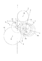
- FIG. 5 is a diagram of the electric motor 2, the cone ring CVT 3, and the differential device 5 as seen from the axial direction.
- the input side friction wheel 22 of the cone ring type CVT 3 is disposed on the first shaft I coaxial with the engine output shaft and the input shaft 6, and the output side friction wheel 23 is disposed on the second shaft II.
- the second axis II is arranged above the first axis I, and the differential device 5 (denoted as a differential gear 41) is a vertical line below the second axis II and passing through the second axis II. It is arranged on the opposite side to the first axis I with respect to vv.
- the input side friction wheel 23 on the first shaft I is disposed so as to surround the ring 25, and the ring 25 is the outermost UD that contacts the minimum diameter portion of the input side friction wheel 22 and the maximum diameter portion of the output side friction wheel 23.
- (underdrive) position (25 2 hereinafter) the highest OD in contact with the minimum diameter portion of the maximum diameter portion and the output-side friction wheel 23 on the input side friction wheel 22 (overdrive) positions (25 1 hereinafter) Is moved in the axial direction so that the center of the ring 25 coincides with the line pp passing through the axes I and II of the friction wheels 22 and 23.
- axes such as the first axis, the second axis, the third axis, and the fourth axis mean axis centers (the same applies to the fifth axis). Further, the first axis, the second axis, the third axis, the fourth axis, and the fifth axis are all arranged in parallel and mean different independent axes (lines).
- the third shaft III on which the electric motor 2 is disposed is above the second shaft II, preferably above a horizontal line hh passing through the upper end u of the maximum diameter portion of the output side friction wheel 23, and It is arranged on the first axis I side with respect to the vertical line vv passing through the two axes II.
- the outer periphery 2c of the motor case 9a of the electric motor 2 is arranged so as to intersect a horizontal line hh passing through the upper end u of the maximum diameter portion of the output friction wheel 23.
- the electric motor 2 is arranged so as to overlap the cone-ring type CVT 3, particularly the input side friction wheel that is coaxial (I) with the engine output shaft, and is compact in the axial direction.
- the third axis III is arranged on the first axis I side with respect to the vertical line vv passing through the second axis II above the first axis I, and therefore surrounds the input side friction wheel 22 on the first axis I.
- the electric motor 2 is arranged above the ring 25.
- the ring 25 moves in parallel with a line pp passing through both axes I and II over the entire movable range. Can be disposed near the cone ring type CVT 3 without interfering with the ring over the entire movable range of the ring 25.
- the electric motor 2 can be arranged as close as possible to the cone ring type CVT 3 by arranging the outer circumference 2c of the motor case 9a of the electric motor 2 to intersect the horizontal line hh.
- the hybrid drive device can be made compact.
- the fourth axis IV on which the differential device 5 is arranged is below the second axis II and on a vertical line vv passing through the second axis II.
- the electric motor 2 is disposed on the input side friction wheel 22 side positioned below the second axis II, and the differential device 5 is disposed on the opposite side of the input side friction wheel 22 with respect to the vertical line vv. It will be.
- the differential device 5 is also arranged close to the cone ring type CVT 3, in particular, the ring 25 so as not to interfere with the ring 25, and the electric motor 2, the cone ring type CVT 3 and the differential device are viewed from the axial direction. It becomes a compact and rational arrangement structure that is arranged together, and can be made into a compact configuration that suppresses the height of the entire hybrid drive device.
- the third axis III on which the electric motor 2 is arranged has a second axis from a vertical line ww passing through the first axis I and perpendicular to the line pp passing through the first axis I and the second axis II. Arranged on the II side. That is, the third axis III is disposed above the second axis II and between the vertical line vv and the vertical line ww.
- the electric motor 2 is also accommodated in the range of the cone ring type CVT 3 also in the left and right (width) direction, and the size reduction is achieved.
- FIG. 6 is a diagram showing an arrangement structure viewed from the axial direction in which the ring 25 of the cone ring type CVT 3 is arranged so as to surround the output side friction wheel 23.
- the third shaft III on which the electric motor 2 is arranged is above the second shaft II, preferably the maximum diameter of the output side friction wheel 23. It is disposed above the horizontal line hh passing through the upper end u of the part and on the first axis I side with respect to the vertical line vv passing through the second axis II.
- the ring 25 is disposed so as to surround the output-side friction wheel 23, the most OD (overdrive) position (denoted as 25 3 ) where the ring 25 approaches the axis I of the input-side friction wheel 22, and the output-side friction wheel 23. between the outermost UD closer to the axis II (underdrive) position (25 4 hereinafter), the both axes I, but moves in parallel to the line p-p through the II, all the movable of the ring 25 Since the position facing the upper side of the range is exclusively on the side opposite to the input side friction wheel 22 with respect to the vertical line vv, the electric motor 22 should be arranged at a close position above the cone ring type CVT 3. Is possible.
- the electric motor 2 is prevented from interfering with the ring 25 and can be disposed near the cone ring type CVT 3, so that the hybrid drive device can be made compact. be able to.
- the fourth axis IV on which the differential device 5 is arranged is first in that it is located below the second axis II and on the opposite side of the first axis I with respect to the vertical line vv passing through the second axis II.
- the distance between the electric motor 2 and the differential device 5, that is, the overall height of the hybrid drive device can be reduced to achieve a compact size.
- the differential device 5 is arranged on the output side friction wheel 23 side surrounded by the ring 25.
- the ring gear 41 having the largest diameter of the differential device 5 is as shown in FIG.
- the hybrid drive device can be compactly assembled as a whole in a position different from the cone ring type CVT 3 in the axial direction without interfering with the CVT.
- the outer periphery of the case 2c of the electric motor 2 intersects the horizontal line hh passing through the upper end u of the large-diameter portion of the output side friction wheel.
- the electric motor can be arranged as close as possible to the cone-ring CVT 3 without interfering with the ring 25.
- the third axis III is above the second axis II and between the vertical line vv and a line ww perpendicular to the line pp connecting the first axis I and the second axis II.
- the electric motor 2 can be arranged close to the top of the cone ring type CVT 3 without interfering with the ring 25, and the lateral width of the entire hybrid drive device can be made compact.
- the speed change operation means 60 includes a feed screw shaft 61 disposed in the upper space F of the input side friction wheel 22 and a guide disposed in the lower space J serving as the oil reservoir 59.
- the rail 62 and the moving member 63 arrange
- the feed screw shaft 61 and the guide rail 62 are arranged in a vertical position with the input side friction wheel 22 in between, and are arranged in parallel to each other, and in parallel so that the two conical friction wheels 22 and 23 are along the opposing inclined surfaces.
- the feed screw shaft 61 is rotatably supported by the case member 9, and an electric motor A 2 that is an electric actuator is interlocked with the outside of the case member 9. It is appropriately rotated by a drive signal from the control unit according to the traveling state of the vehicle.
- the moving member 63 is supported so as to be movable in the axial direction across the feed screw shaft 61 and the guide rail 62, and a ball nut portion 65 that is screwed to the feed screw shaft 61 is fixed to the upper portion of the moving member 63.
- a slide portion 66 supported by the guide rail 62 so as to be movable in the axial direction is fixed to the lower portion.
- An upper (first) support member 67 is installed on the inner surface side opposite to the ball nut portion 65 of the moving member 63, and lower (second) on the inner surface side opposite to the slide portion. )
- a support member 69 is installed.
- the upper support member 67 and the lower support member 69 are arranged on different sides with respect to the plane including the axes l-l and n-n of the friction wheels 22 and 23 on both the input side and the output side. However, both support members 67 and 69 are arranged so as to support the ring 25 at a position farthest from the plane.
- the axial movement for shifting the ring 25 is a direction in which the moving member 63 moves along the feed screw shaft 61 and the guide rail 62 that are parallel to each other, that is, the friction wheels 22 and 23 in contact with the rings. It means the direction along the opposite slope and is different from the axis of both friction wheels.
- the ring 25 is positioned so that its central axis is parallel to the above-mentioned opposing slope, and therefore the upper and lower ends of the ring are parallel to the plane (pp) including the axial centers I and II of both friction wheels. Move along the plane.
- the upper support member 67 and the lower support member 69 can support the ring 25 so as to sandwich the ring 25, and move integrally with the moving member 63 to move the ring 25 in the axial direction.
- the members 67 and 69 support the ring 25 from both sides when the ring 25 is on the upstream side in the rotational direction where the ring 25 is drawn into the contact portion with the two friction wheels 22 and 23, so that the members are defined in the axial direction.
- it has a structure that allows the axial movement (swing) of the ring 25 on the downstream side in the rotational direction pushed out from the contact portion.
- the ring 25 is supported so as to be picked by the upper or lower support member 67 or 69 located upstream of the friction wheel regardless of whether the friction wheel is rotating forward or backward, and the position based on the movement or stop of the moving member 63. Accordingly, either the upper or lower support member 69 or 67 allows the swing of the ring 25 in the above movement or stop at that time, and the ring 25 is autonomously supported.
- the ring 25 has an inclination angle (including an inclination angle 0 orthogonal to the axis) determined by the contact portion between the friction member and the support member 67 or 69 on the upstream side of the rotation that regulates axial movement. Since the ring is supported at a position farthest from the contact portion, the inclination angle of the ring is stable, an accurate gear shifting operation and a constant speed maintaining operation can be easily performed, and the moving member 63 The angle of inclination of the ring according to the moving speed can be set easily and reliably, and a shift with a quick response speed is possible.
- the moving member 63 has a connecting portion extending in an arc shape along the outside of the input side friction wheel 22 over a ball nut portion 65 located at the upper end and a slide portion 66 located at the lower end, A concave groove 71 having a predetermined width and a predetermined depth is formed on the inner peripheral surface of the connecting portion so as to receive the ring 25.
- An oil guide 72 is fixed to the tip of the lower end of the moving member 63.
- the oil guide 72 has a U-shaped cross section and a circular arc shape with a predetermined angle, and is made of a sheet metal member that receives the ring 25 in the recess.
- the tip of the oil guide 72 is a free end at a position approaching the contact portion between the ring and the friction wheel within a range not interfering with the output side friction wheel 23, and extends along the outer periphery of the ring 25. .
- the recesses 71 and the recesses of the oil guide 72 are set to a width that does not interfere with the ring 25 even if the ring 25 is tilted during a shifting operation.
- the moving member 63 has the recessed groove 71 which receives the ring 25 in the inner peripheral surface, the dimension which protrudes to the ring outer-diameter side can be made small, and the compactness of cone ring type CVT3 can be improved.
- the guide rail 62 and the slide portion 66 are immersed in the oil reservoir 59 over the entire movable range in the axial direction (movement direction). Further, the lower support member 69 is also immersed in the oil reservoir 59 over the entire movable range in the axial direction (moving direction) of the moving member 63. On the other hand, the ball nut portion 65 and the feed screw shaft 61 positioned above the moving member 63 are positioned above the oil level 59a over the entire movable range in the axial direction (moving direction).
- the upper support member 67 is also positioned above the oil level 59 a over the entire movable range of the moving member 63 in the axial direction (moving direction) and does not immerse in the oil reservoir 59.
- the input side friction wheel 22 rotates in the direction of arrow K in FIG. 4
- the ring 25 is oil in the entire movable range in its axial direction (moving direction). From the state immersed in the reservoir 59, it rotates upward toward the contact portion between the friction wheels 22 and 23.
- the guide rail 62 and the slide portion 66 are immersed in the oil reservoir 59 over the entire movable range in the moving direction.
- the guide rail 62 and the slide portion 66 do not necessarily have to be immersed in the entire movable range. You may arrange
- the speed change operation means 60 always has its guide rail 62 and slide portion 66 in the oil reservoir 59.
- the feed screw mechanism including the feed screw shaft 61 and the ball nut portion 65 is located above the oil level 59a.
- the moving member 63 is smoothly translated in parallel, but the feed screw mechanism is always located above the oil level 59a and does not stir the oil in the oil reservoir 59, and no energy loss is caused by the oil stirring. .
- the ring 25 also rotates in the direction of arrow K in FIG. 4, and the ring 25 scoops up oil in the oil reservoir 59, and the oil drawn by the ring is guided to the oil guide 72. However, it is guided to the contact portion with the friction wheels 22 and 23. A sufficient amount of traction oil by the oil guide 72 is interposed in the contact portion between the ring 25 and the two friction wheels 22 and 23, whereby reliable frictional power transmission by the above-described shearing force is performed and accompanying rotation.
- the smooth movement of the ring 25 in the axial direction is performed, and an accurate and quick shifting operation is performed. Further, a part of the oil is accompanied with the ring 25 and supplied to the upper support member 67, and is scattered by centrifugal force and supplied to the feed screw shaft 61 and the ball nut portion 65. Further, a part of the oil adhering to the ring 25 is guided to the concave groove 71 of the moving member 63 and returned to the oil reservoir 59.
- the oil splashed from the ring 25 and supplied to the feed screw shaft 61 is supplied to the screw shaft 61 where the screwing with the ball nut portion 65 is about to proceed, and the feed screw is moved in accordance with the movement of the ring 25.
- the feed screw shaft portion that requires lubrication consisting of a portion where the shaft and the nut portion are screwed together is properly supplied, and even if the feed screw shaft is above the oil level 59a, the movable member can be smoothly moved by appropriate lubrication. 63 can be moved.
- the guide rail 62 and the slide portion 66 are immersed in the oil reservoir 59 to smoothly guide the moving member 63 by sufficient lubrication, and the slide operation of the slide portion 66 can be performed even if immersed in the oil reservoir 59. There is little influence on the stirring of the pool.
- the lower support member 69 immersed in the oil reservoir 59 serves as an operating portion that regulates the axial movement of the ring 25, and the operating portion smoothens the ring 25 in the oil reservoir 59.
- the axial movement can be defined.
- the upper support member 67 allows the ring 25 to move in the axial direction, the upper support member 67 is sufficiently lubricated by the oil attached to the ring 25 and does not impair the rotation of the ring 25.
- the ring 25 rotates in the direction of the opposite arrow K, and the oil scooped up by the ring 25 immersed in the oil sump 59 is guided to the concave groove 71 of the moving member 63. It is turned and guided to the upper support member 67.
- the upper support member 67 serves as an operating part that regulates the axial movement of the ring.
- the ring 25 is lubricated by a relatively sufficient oil guided in the concave groove 71. The movement in the axial direction is defined while smoothly rotating.
- the oil further accompanied by the rotation of the ring 25 is supplied to the contact portion between the ring and the friction wheel, and the frictional transmission by the shearing force and the axial movement of the ring 25 are performed.
- the amount of oil in the contact portion between the upper support member 67 and the ring and the friction wheel which is the axial positioning operation portion of the ring is small in the reverse rotation as compared with the normal rotation, but the reverse drive state of the vehicle is Compared to the time of forward movement, the usage time is overwhelmingly small, and the required torque capacity and the speed change range are also small. Therefore, even if the oil amount is relatively small, the frictional power transmission and the speed change operation are not hindered. Thus, power transmission and speed change operation can be performed accurately and smoothly.
- the speed change operation means 60 moves in the axial direction so as to grip the rotation upstream side of the contact portion of the ring 25, and is not limited to this, but is operated to incline the ring 25 to incline the ring. It may move in the axial direction along a corner (see, for example, WO 2005/061928).
- the present invention relates to a hybrid drive system using an internal combustion engine and an electric motor as drive sources, and is applicable to all automobiles such as passenger cars, buses and trucks, agricultural work vehicles such as tractors, and construction work vehicles such as bulldozers. It can be used for vehicles.
Landscapes
- Engineering & Computer Science (AREA)
- Chemical & Material Sciences (AREA)
- Combustion & Propulsion (AREA)
- Transportation (AREA)
- Mechanical Engineering (AREA)
- Hybrid Electric Vehicles (AREA)
- Friction Gearing (AREA)
Abstract
コーンリング式CVTをハイブリッド駆動装置に適用し、装置全体としてコンパクトな配置とする。入力側摩擦車(22)をエンジン出力軸と同軸の第1軸(I)に配置し、出力側摩擦車(23)を第2軸(II)に配置し、電気モータ(2)を第1軸、第2軸に平行な第3軸(III)に配置する。電気モータ(2)とコーンリング式CVT(3)を軸方向に一部が重なるように配置する。第3軸(III)は、第2軸(II)の上方で、かつ該第2軸を通る鉛直線(v-v)より第1軸(I)側に配置される。
Description
本発明は、エンジンと電気モータとで車輪を駆動し得るハイブリッド駆動装置に係り、詳しくは電気モータと、円錐摩擦車リング式無段変速装置(コーンリング式CVT)とを一体に組込んだハイブリッド駆動装置に関する。
従来、エンジンと電気モータとで車輪を駆動するハイブリッド駆動装置にあって、1個の電気モータと無段変速装置とを組合せたものが知られている。一般に、該ハイブリッド駆動装置用の無段変速装置として、1対のプーリとこれらプーリに巻掛けられる金属製ベルト(又はチェーン)からなり、プーリの有効径を変更することにより無段に変速するベルト式無段変速装置が用いられている。
一方、1対の円錐状の摩擦車とこれら摩擦車の間に介在する金属製のリングとからなり、リングを、前記両摩擦車との接触部を変更するように移動することにより無段に変速するコーンリング式CVTが知られている(例えば特許文献1参照)。
最近、上記コーンリング式CVTをハイブリッド駆動装置に用いた特許文献が公開された(特許文献2参照)。該ハイブリッド駆動装置は、内燃エンジンの出力軸と同軸の第1軸上に、前記コーンリング式CVTの入力側の円錐形状の摩擦車が配置されており、電気モータは、上記第1軸上又は他の軸上に配置されている。
一般に、ハイブリッド駆動装置は、エンジン出力軸と同軸の第1軸上に、電気モータ及びベルト式無段変速装置のプライマリプーリが配置されている。上記コーンリング式CVTをハイブリッド駆動装置に適用することも考えられるが、該コーンリング式CVTの円錐形状の摩擦車は、軸方向に比較的長い構成からなり、前記エンジン出力軸と同軸の第1軸上に、電気モータと共に入力側摩擦車を配置することは、第1軸が長くなって、車輌搭載上好ましくない。また、上記特許文献2には、電気モータを第1軸以外の軸に配置された実施の形態も記載されているが、いずれも、電気モータは、コーンリング式CVTとは軸方向に重ならない位置に配置されており、電気モータ用としての専用の軸方向スペースを必要としている。コーンリング式CVTと電気モータを組合せたハイブリッド駆動装置として、コンパクトに構成され、車輌搭載性を向上することが求められている。
そこで、本発明は、コーンリング式無段変速機と電気モータとを、コンパクトに配置することにより、車輌搭載性を向上したハイブリッド駆動装置を提供することを目的とするものである。
本発明は、エンジン出力軸(54)に連結する入力軸(6)と、
電気モータ(2)と、
互いに平行な軸(l-l)(n-n)上に配置されかつ大径側と小径側とが逆になるように配置された円錐形状の入力側摩擦車(22)及び出力側摩擦車(23)と、これら両摩擦車の一方を囲むようにして両摩擦車の対向する傾斜面に挟持されるリング(25)と、該リングを移動して変速操作する変速操作手段(60)と、を有する円錐摩擦車リング式無段変速装置(コーンリング式CVT)(3)と、を備え、
前記入力軸(6)の回転を前記円錐摩擦車リング式無段変速装置(3)を介して出力部(39l,39r)に伝達すると共に、前記電気モータ(2)の動力を前記出力部(39l,39r)に伝達してなるハイブリッド駆動装置(1)において、
エンジン出力軸と同軸の第1軸(I)上に、前記入力側摩擦車(22)及び前記入力軸(6)を配置し、
前記第1軸(I)に平行でかつ該第1軸より上方に位置する第2軸(II)上に、前記出力側摩擦車(23)を配置し、
前記第1軸(I)及び第2軸(II)に平行な第3軸(III)上に、前記電気モータ(2)を配置し、
前記円錐摩擦車リング式駆動装置(コーンリング式CVT)(3)と前記電気モータ(2)とが、径方向からみて、軸方向に少なくとも一部が重なるように配置され(例えば図2参照)、
軸方向からみて(例えば図5及び図6参照)、前記第3軸(III)は、前記第2軸(II)より上方で、かつ該第2軸(II)を通る鉛直線(v-v)より前記第1軸(I)側に配置されてなる、
ことを特徴とするハイブリッド駆動装置にある。
電気モータ(2)と、
互いに平行な軸(l-l)(n-n)上に配置されかつ大径側と小径側とが逆になるように配置された円錐形状の入力側摩擦車(22)及び出力側摩擦車(23)と、これら両摩擦車の一方を囲むようにして両摩擦車の対向する傾斜面に挟持されるリング(25)と、該リングを移動して変速操作する変速操作手段(60)と、を有する円錐摩擦車リング式無段変速装置(コーンリング式CVT)(3)と、を備え、
前記入力軸(6)の回転を前記円錐摩擦車リング式無段変速装置(3)を介して出力部(39l,39r)に伝達すると共に、前記電気モータ(2)の動力を前記出力部(39l,39r)に伝達してなるハイブリッド駆動装置(1)において、
エンジン出力軸と同軸の第1軸(I)上に、前記入力側摩擦車(22)及び前記入力軸(6)を配置し、
前記第1軸(I)に平行でかつ該第1軸より上方に位置する第2軸(II)上に、前記出力側摩擦車(23)を配置し、
前記第1軸(I)及び第2軸(II)に平行な第3軸(III)上に、前記電気モータ(2)を配置し、
前記円錐摩擦車リング式駆動装置(コーンリング式CVT)(3)と前記電気モータ(2)とが、径方向からみて、軸方向に少なくとも一部が重なるように配置され(例えば図2参照)、
軸方向からみて(例えば図5及び図6参照)、前記第3軸(III)は、前記第2軸(II)より上方で、かつ該第2軸(II)を通る鉛直線(v-v)より前記第1軸(I)側に配置されてなる、
ことを特徴とするハイブリッド駆動装置にある。
なお、第1軸、第2軸及び第3軸は(後述の第4軸も含む)、それぞれ独立した専用の軸を意味し(共用するものは含まない)、各軸は、その軸心を意味する。また、電気モータ(2)は、前記コーンリング式CVT(3)を介して前記出力部(39l,39r)に駆動連結しても、また該コーンリング式CVTを介することなく、直接前記出力部に駆動連結してもよい。
例えば図5及び図6を参照して、軸方向からみて、前記第3軸(III)は、前記第1軸(I)を通り、かつ前記第1軸(I)と第2軸(II)とを通る線(p-p)に垂直な線(w-w)より前記第2軸(II)側に配置されてなる。
例えば図5及び図6を参照して、軸方向からみて、前記電気モータ(2)のケースの外周(2c)が、前記出力側摩擦車の最大径部の上端(u)を通る水平線(h-h)と交わるように配置されてなる。
例えば図2,図5及び図6を参照して、前記出力側摩擦車(23)に連結する出力軸(24)からの動力を入力して左右の前記出力部(39l,39r)に出力するディファレンシャル装置(5)を備え、
前記第1軸(I)、第2軸(II)及び第3軸(III)に平行な第4軸(IV)上に、前記ディファレンシャル装置(5)を配置し、
軸方向からみて、前記第4軸(IV)は、前記第2軸(II)の下方でかつ該第2軸(II)を通る鉛直線(v-v)に対して前記第1軸(I)の反対側に配置されてなる。
前記第1軸(I)、第2軸(II)及び第3軸(III)に平行な第4軸(IV)上に、前記ディファレンシャル装置(5)を配置し、
軸方向からみて、前記第4軸(IV)は、前記第2軸(II)の下方でかつ該第2軸(II)を通る鉛直線(v-v)に対して前記第1軸(I)の反対側に配置されてなる。
例えば図5に示すように、前記リング(25)が、前記入力側摩擦車(22)を囲むように配置されてなる。
例えば図6に示すように、前記リング(25)が、前記出力側摩擦車(23)を囲むように配置されてなる。
なお、上記カッコ内の符号は、図面と対照するためのものであるが、これにより特許請求の範囲記載の構成に何等影響を及ぼすものではない。
請求項1に係る本発明によると、コーンリング式CVTが配置される第1軸及び第2軸と平行な第3軸に電気モータが配置され、かつコーンリング式CVTと電気モータとが軸方向に少なくとも一部が重なるように配置されているので、例えばエンジン出力軸と同軸の第1軸等の一部の軸が長くなることを防止して、軸方向のコンパクト化を図ることができるものでありながら、軸方向からみて、入力軸摩擦車が配置される第1軸より上方に出力側摩擦車が配置される第2軸が配置され、かつ第3軸が、上記第2軸の上方で、かつ該第2軸を通る鉛直線(v-v)より第1軸側に配置されるので、電気モータは、リングとの干渉を防止されて、コーンリング式CVT近くに配置することが可能となり、径方向のコンパクト化も図ることができ、これらが相俟って、軸方向及び上下(高さ)方向に対してコンパクトな構成で、車輌搭載性能を向上したハイブリッド駆動装置を提供することができる。
請求項2に係る本発明によると、第3軸は、第1軸を通り、第1軸と第2軸とを通る線(p-p)に垂直な線(w-w)より第2軸側、即ち第2軸IIの上方で、上記鉛直線(v―v)と、上記垂直線(w-w)との間に配置されるので、電気モータは、コーンリング式CVTの上方で近接して配置され、左右(幅)方向のコンパクト化も図ることができる。
請求項3に係る本発明によると、電気モータのケースの外周が、出力側摩擦車の最大径部の上端を通る水平線(h-h)に交わるように配置されるので、電気モータをコーンリング式CVTに可及的に近接して配置することが可能となり、ハイブリッド駆動装置のコンパクト化を確実化することができる。
請求項4に係る本発明によると、ディファレンシャル装置が配置される第4軸と、電気モータが配置される第3軸III及び入力摩擦車が配置される第1軸とは、第2軸を通る鉛直線(v-v)に対して反対側でかつ第4軸が第2軸の下方に配置されるので、ディファレンシャル装置から電気モータまでの高さを抑えて、ハイブリッド駆動装置全体をコンパクトに構成することができる。
請求項5に係る本発明によると、電気モータは、出力側摩擦車に対してリングに囲まれている入力側摩擦車側に配置されるが、該入力軸摩擦車が配置される第1軸が出力側摩擦車が配置される第2軸の下方に位置するため、該リングは、その全可動範囲において上記電気モータとの干渉が防止され、径方向のコンパクト化が達成される。
請求項6に係る本発明によると、電気モータは、リングに囲まれている出力側摩擦車の軸心を通る鉛直線(v-v)より入力側摩擦車側に配置されているので、出力側摩擦車が配置される第2軸が入力側摩擦車より上方に位置しても、上記リングの斜め上方側への移動は、上記鉛直線から離れる方向となって、リングの全可動範囲において上記電気モータとの干渉が防止され、径方向のコンパクト化を達成することができる。
図面に沿って、本発明を適用したハイブリッド駆動装置を説明する。ハイブリッド駆動装置1は、図1及び図2に示すように、電気モータ2と、円錐摩擦車リング式無段変速装置(コーンリング式CVT)3と、ディファレンシャル装置5と、図示しないエンジンの出力軸54とクラッチ4を介して連結する入力軸6と、ギヤ伝動装置7とを有する。上記各装置及び軸は、2個のケース部材9,10を合せて構成されるケース11に収納されており、かつ該ケース11は、隔壁12により第1の空間Aと第2の空間Bとに油密状に区画されている。
電気モータ2は、第1のケース部材9に固定されたステータ2aと出力軸8に設けられたロータ2bとを有し、出力軸8は、一方側端部が第1のケース部材9にベアリング13を介して回転自在に支持されていると共に他方側端部が第2のケース部材10にベアリング15を介して回転自在に支持される。出力軸8の一方側には歯車(ピニオン)からなる出力ギヤ16が形成されており、該出力ギヤ16はアイドラ歯車17を介して入力軸6に設けられた中間ギヤ(歯車)19に噛合している。電気モータ2のステータ2aは、第1のケース部材9により形成される有底円筒状のモータケース9aにより覆われており、かつ出力ギヤ16部分は、図3に示すように、上記モータケース9aの端面に接合し、かつアイドラギヤ17との噛合用に切欠かれた、第2のケース部材10のモータ部10dにより覆われている。
コーンリング式CVT3は、入力側である円錐形状の(一方の円錐形)摩擦車22と、出力側である同じく円錐形状の(他方の円錐形)摩擦車23と、金属製のリング25とからなる。前記両摩擦車22,23は、その軸l-l,n-nが互いに平行にかつ大径側と小径側が軸方向に逆になるように配置されており、上記リング25が、これら両摩擦車22,23の対向する傾斜面に挟持されるようにかつ両摩擦車のいずれか一方例えば入力側摩擦車22を取囲むように配置されている。両摩擦車の少なくとも一方には大きなスラスト力が作用しており、上記リング25は上記スラスト力に基づく比較的大きな挟圧力により挟持されている。具体的には、出力側摩擦車23と無段変速装置出力軸24との間には軸方向で対向する面にボールを介在した傾斜カム機構からなる軸力付与手段28(図1参照)が形成されており、該軸力付与手段(カム機構)28は、出力側摩擦車23に、伝達トルクに応じた矢印D方向のスラスト力が発生し、該スラスト力に対抗する方向に支持されている入力側摩擦車22との間でリング25に大きな挟圧力が生じる。
入力側摩擦車22は、その一方側(大径側)端部がローラベアリング26を介して第1のケース部材9に支持されると共に、その他方側(小径側)端部がテーパードローラベアリング27を介して隔壁12に支持されている。出力側摩擦車23は、その一方側(小径側)端部がローラ(ラジアル)ベアリング29を介して第1のケース部材9に支持されると共に、その他方側(大径側)端部がローラ(ラジアル)ベアリング30を介して隔壁12に支持されている。該出力側摩擦車23に上述した矢印D方向のスラスト力を付与した出力軸24は、その他方側端がテーパードローラベアリング31を介して第2のケース部材10に支持されている。入力側摩擦車22の他方側端部は、ベアリング27のインナレースを段部及びナット32により挟持されており、該入力側摩擦車22にリング25を介して作用する出力側摩擦車23からのスラスト力が、上記テーパードローラベアリング27により担持される。一方、出力軸24には、出力側摩擦車23に作用するスラスト力の反力が反矢印D方向に作用し、該スラスト反力が上記テーパードローラベアリング31により担持される。
上記リング25は、変速操作手段(後述)により軸方向に移動して、入力側摩擦車22及び出力側摩擦車23の接触位置を変更して、入力部材22と出力部材23との間の回転比を無段に変速する。上記伝達トルクに応じたスラスト力Dは、上記両テーパードローラベアリング27,31を介して一体的なケース11内にて互いに打消され油圧等の外力としての平衡力を必要としない。
ディファレンシャル装置5はデフケース33を有しており、該デフケース33は、その一方側端部が第1のケース部材9にベアリング35を介して支持されていると共に他方側端部が第2のケース部材10にベアリング36を介して支持されている。該デフケース33の内部には軸方向に直交するシャフトが取付けられており、該シャフトにデフキャリヤとなるベベルギヤ37,37が係合されており、また左右のアクスル軸(出力部)39l,39rが支持され、これらアクスル軸に上記デフキャリヤと噛合するベベルギヤ40,40が固定されている。更に、上記デフケース33の外部には大径のデフリングギヤ(入力部)41が取付けられている。
前記無段変速装置出力軸24にギヤ(ピニオン)44が形成されており、該ギヤ44に前記デフリングギヤ41が噛合している。前記モータ出力ギヤ(ピニオン)16、アイドラ歯車17及び中間ギヤ(歯車)19、並びに無段変速装置出力ギヤ(ピニオン)44及びデフリングギヤ(歯車)41が前記ギヤ伝動装置7を構成している。上記モータ出力ギヤ16とデフリングギヤ41とが、軸方向でオーバラップするように配置されており、更に中間ギヤ19及び無段変速装置出力ギヤ44が、モータ出力ギヤ16及びデフリングギヤ41と軸方向でオーバラップするように配置されている。なお、無段変速装置出力軸24にスプライン係合されているギヤ45は、シフトレバーのパーキング位置にて出力軸をロックするパーキングギヤである。また、ギヤとは、歯車及びスプロケットを含む噛合回転伝達手段を意味するが、本実施の形態においては、ギヤ伝動装置は、すべて歯車からなる歯車伝動装置である。なお、ギヤ伝動装置にチェーン及びスプロケットを用いてもよく、また電気モータ2の出力ギヤ16をギヤ伝動装置7のみを介して(従ってコーンリング式CVT3を介することなく)出力ギヤ44に伝達してもよい。
前記入力軸6は、ボールベアリング46にて第2のケース部材10に支持され、かつその一端にて無段変速装置3の入力部材22にスプラインSにより係合(駆動連結)しており、かつその他端側は、第2のケース部材10により形成される第3の空間C内に収納されるクラッチ4を介してエンジンの出力軸54に連動している。第2のケース部材10の上記第3の空間C側は開放されており、図示しないエンジンに連結される。
前記ギヤ伝動装置7は、電気モータ2及び前記第1の空間Aと第3の空間Cとの軸方向間部分となる第2の空間B内に収納されており、該第2の空間Bは、第2のケース部材10と隔壁12とにより形成される。前記隔壁12の軸支持部分(27,30)は、オイルシール47a,47bにより油密状に区画されていると共に、第2のケース部材10及び第1のケース部材9の軸支持部分もオイルシール47c,47d,47eにより軸封されて、上記第2の空間Bは油密状に構成されており、該第2の空間BにはATF等の潤滑用オイルが所定量充填されている。第1のケース部材9及び隔壁12で形成される第1の空間Aも、同様に油密状に構成されており、該第1の空間Aには、剪断力、特に極圧状態における剪断力の大きなトラクション用オイルが所定量充填されている。
前記電気モータ2のステータ2a及びコーンリング式CVT3は、同じ第1のケース部材9に収納されて、図2に示すように、(径方向からみて)軸方向に重なるように配置されている。なお、図2にあっては、電気モータ2のステータ2aが、コーンリング式CVT3の軸方向範囲に含まれるように完全に重なっているが、電気モータ2とコーンリング式CVT3とは、少なくとも一部が軸方向に重なっていればよい。
クラッチ4は、図1に概略を示すように、乾式単板クラッチからなり、エンジン出力軸54に連結されているクラッチディスク4a及び前記入力軸6にダンパスプリング55を介して連結されている出力側となるプレッシャプレート4bを有し、プレッシャプレートは、ダイヤフラムスプリング56により常時クラッチディスクに接続するように付勢されている。また、レリーズベアリング57が上記プレッシャプレートの中心部分に回転自在に当接しており、該ベアリング57がレリーズフォーク58により押圧されることにより、上記クラッチ4が切操作される。レリーズフォーク58は、ロッド53を介してウォームホイール50に連結されており、該ホイールには電動アクチュエータである電気モータA1の出力軸に連動されているウォーム52が噛合している。
上記電気モータA1、ウォーム52、ウォームホイール50及びロッド53は、クラッチ操作手段51を構成しており、前記電動アクチュエータ(電気モータ)A1に基づく該クラッチ操作手段51の操作により上記クラッチ4を断接操作すると共に、上記非可逆機構からなるウォーム52及びウォームホイール50が介在して、電気モータA1が停止した状態でのクラッチ4の操作位置(接続又は切断)に保持される。
ついで、上述したハイブリッド駆動装置1の作動について説明する。本ハイブリッド駆動装置1は、ケース11の第3の空間C側を内燃エンジンに結合され、かつ該エンジンの出力軸をクラッチ4を介して入力軸6に連動して用いられる。エンジンからの動力が伝達される入力軸6の回転は、スプラインSを介してコーンリング式CVT3の入力側摩擦車22に伝達され、更にリング25を介して出力側摩擦車23に伝達される。
この際、両摩擦車22,23とリング25との間は、出力側摩擦車23に作用する矢印D方向のスラスト力により大きな接触圧が作用し、かつ第1の空間Aはトラクション用オイルが充填されているので、上記両摩擦車とリングとの間には、該トラクション用オイルの油膜が介在した極圧状態となる。この状態では、トラクション用オイルは大きな剪断力を有するので、該油膜の剪断力により両摩擦車とリングとの間に動力伝達が行われる。これにより、金属同士の接触でありながら、摩擦車及びリングが摩耗することなく、所定のトルクを滑ることなく伝達し得、かつリング25を軸方向に滑らかに移動することにより、両摩擦車との接触位置を変更して無段に変速する。
該無段変速された出力側摩擦車23の回転は、その出力軸24、出力ギヤ44及びデフリングギヤ41を介してディファレンシャル装置5のデフケース33に伝達され、左右のアクスル軸39l,39rに動力分配されて、車輪(前輪)を駆動する。
一方、電気モータ2の動力は、出力ギヤ16、アイドラ歯車17及び中間ギヤ19を介して入力軸6に伝達される。該入力軸6の回転は、先の説明と同様に、コーンリング式CVT3を介して無段に変速され、更に出力ギヤ44、デフリングギヤ41を介してディファレンシャル装置5に伝達される。上記各ギヤ16,17,19,44,41,37,40からなるギヤ伝動装置7は、潤滑用オイルが充填される第2の空間Bに収納されており、各ギヤの噛合に際して潤滑用オイルが介在して滑らかに動力伝達される。この際、第2の空間Bの下方位置に配置されたデフリングギヤ41は、大径ギヤからなることと相俟って、潤滑用オイルをかき上げ、他のギヤ(歯車)16,17,19,44並びベアリング27,30,20,21,31,46に確実にかつ充分な量の潤滑用オイルを供給する。
この点について、図3に沿って詳しく説明する。各ギヤ41,16,17,19,44は、第2の空間B内で、次のように配置されている。モータ出力ギヤ16、デフリングギヤ41及びギヤ伝動装置7を構成する複数のギヤ17,19,44のうち、デフリングギヤ41が最も下方に位置する。即ち、ディファレンシャル装置5の中心軸IVは、モータ軸III及び入力軸I、更には出力軸II及びアイドラ軸Vよりも下方に位置する。また、デフリングギヤ41は、その一部が潤滑用オイルのオイル溜り48に浸され、かつ、その一部がオイル溜り48の油面48aよりも上方に突出するように配置されている。また、モータ出力ギヤ16及び複数のギヤ17,19,44は、油面48aよりも上方に配置されており、このうちのモータ出力ギヤ16が最も上方に位置する。したがって、モータ出力ギヤ16が、各ギヤ16,17,19,44のうちの最も上方に位置する最上方ギヤである。なお、油面48aは、デフリングギヤ41の回転抵抗を低減すべく、デフリングギヤ41の回転軸IVよりも下方とすることが好ましい。即ち、デフリングギヤ41の回転軸IVを通る水平線Nよりも下の部分がオイル溜り48に浸かるようにする。
また、デフリングギヤ41は、各ギヤ16,17,19,44よりも図3の左方に位置し、車輌の前進時に所定の回転方向である矢印β方向に回転する。また、モータ出力ギヤ16とアイドラギヤ17と中間ギヤ19とでギヤ列Yを構成している。アイドラギヤ17及び中間ギヤ19は、モータ出力ギヤ16の下方に順番に配置されており、各ギヤ17,19の中心軸(アイドラ軸V、入力軸I)がモータ出力ギヤ16の中心軸(モータ軸III)を通る垂線(鉛直方向の線)γよりもデフリングギヤ41と反対側に位置するようにしている。モータ軸IIIは、軸方向から見て水平方向(図3の左右方向)に関して入力軸Iとディファレンシャル装置5の中心軸IVとの間に配置される。また、出力ギヤ44は、中間ギヤ19よりもデフリングギヤ41側で該デフリングギヤ41の上方に配置されている。更に、これら各ギヤ41,16,17,19,44のうち、最も外径が大きいギヤはデフリングギヤ41である。一方、出力ギヤ44の外径は、各ギヤ41,17,19よりも十分に小さい(小径である)。
各ギヤ41,16,17,19,44の径方向に関する配置は上述の通りであるが、軸方向に関しては、図1に示すように、それぞれの歯部分が軸方向にオーバラップするように配置されている。即ち、デフリングギヤ41は、少なくとも一部がモータ出力ギヤ16及び複数のギヤ17,19,44と軸方向に重なるように配置されている。本実施形態の場合、デフリングギヤ41の歯部分の軸方向の幅の範囲内に、各ギヤ16,17,19,44の歯部分の軸方向の幅の全部又は殆どの部分が存在するようにしている。
デフリングギヤ41とギヤ列Yと案内壁面gとで囲まれる空間を空間部分Xとしている。したがって、出力ギヤ44はこの空間部分X内に配置される。このように構成される本実施形態の場合、デフリングギヤ41を正転回転方向βに回転させて、潤滑用オイルを、デフ側壁面eから案内壁面fに沿って掻上げ、モータ出力ギヤ16及び複数のギヤ17,19,44、更には、第2の空間B内に存在する各ベアリング15,20,21,46,31,27,30にも供給可能としている。即ち、デフリングギヤ41は、他のギヤに比べて大径であり、回転により外周面に形成された歯と歯の間の凹部内に存在する潤滑用オイルが大きな遠心力で飛ばされ、遠心力が作用した潤滑用オイルが案内壁面gに沿って掻き揚げられ、この案内壁面gに沿って、或は、この案内壁面gの内側の空間部分X内を飛翔する。空間部分Xを介して飛翔した潤滑用オイルの一部は、各ギヤ17,19,44にも供給されると共に、モータ出力ギヤ16に到達した潤滑用オイルは、下方に流れて、モータ出力ギヤ16の下方に位置する各ギヤ17,19,44にも供給される。また、上述のようにデフリングギヤ41により掻上げられる潤滑用オイルは、第2の空間B内に存在する各ベアリング15,20,21,46,31,27,30にも供給される。なお、デフケース33を支持するベアリング35,36は、少なくとも一部が潤滑用オイルに浸かっている。
上記エンジン及び電気モータの作動形態、即ちハイブリッド駆動装置1として作動形態は、必要に応じて各種採用可能である。一例として、車輌発進時、クラッチ4を切断すると共にエンジンを停止し、電気モータ2のトルクのみにより発進し、所定速度になると、エンジンを始動すると共にクラッチ4を接続して、エンジン及び電気モータの動力により加速し、巡航速度になると、電気モータをフリー回転又は回生モードとして、エンジンのみにより走行する。減速、制動時は、電気モータを回生してバッテリを充電する。また、クラッチ4を発進クラッチとして使用し、エンジンの動力により、モータトルクをアシストとして用いつつ発進するように用いてもよい。
リバース時は、クラッチ4を切断すると共にエンジンを停止し、かつ電気モータ2を逆方向に回転駆動する。これにより、モータ出力軸8の逆回転は、ギヤ16,17,19及び低速状態にあるコーンリング式CVT3を介して出力軸24に伝達される。更に、ギヤ44、41を介してディファレンシャル装置5に伝達され、左右のアクスル軸39l,39rを逆回転して、車輌を後進する。
ついで、図4に沿って、円錐摩擦車リング式無段変速装置(コーンリング式CVT)3について説明する。該無段変速装置3は、前述したように、入力側摩擦車22、出力側摩擦車23及びリング25からなり、これら両摩擦車及びリングが鋼等の金属からなる。両摩擦車22,23は、その軸l-l、n-n(図2参照)が水平方向にあって互いに平行になるように配置され、かつ傾斜面が直線からなる円錐形状からなり、対向する両傾斜面の間にリング25が挟持される。リング25は、両摩擦車のいずれか一方、具体的には入力側(一方の円錐形)摩擦車22を囲むように配置され、その周方向に垂直な面での断面が略々平行四辺形からなり、その回転面m-mは、軸l-lに対して略々直交するように設定されている(図7参照)。
上記コーンリング式CVT3は、有底筒状の第1のケース部材9により一端側及びその全周側を覆われており、上記第1のケース部材9の開口側は隔壁12により蓋されて、第1の空間Aに油密状に収納されている。出力側(他方の円錐形)摩擦車23の軸23aが入力側(一方の円錐形)摩擦車22の軸22aより所定量上方に位置するように、両摩擦車は斜めに配置されており、入力側摩擦車22は、その上方、下方及び出力側摩擦車23と反対方向側方においてケース部材9との間に余裕をもって配置されている。上記入力側摩擦車22を囲んでいるリング25は、該入力側摩擦車とケース部材9との間の空間に配置されると共に、該リング25を軸方向に移動する変速操作手段(装置)60が配置されている。なお、図4において、ケース部材9の上方部分9Aは、電気モータ2が配置される部分、9Bは、ディファレンシャル装置5が配置される部分であり、上記上方部分9Aには前記モータケース9aとなって、その下面外周2cがコーンリング式CVT3の収納部分である瓢箪形の一部を構成している。また、上記ケース部材9との間の上記入力側摩擦車22の下方空間Jはトラクション用オイルのオイル溜り59(オイルレベルを59aで表記)となっている。
図5は、電気モータ2、コーンリング式CVT3及びディファレンシャル装置5を軸方向からみた図である。コーンリング式CVT3の入力側摩擦車22は、エンジン出力軸及び入力軸6と同軸の第1軸I上に配置され、出力側摩擦車23が第2軸II上に配置されている。上記第2軸IIは、第1軸Iに対して上方に配置されており、ディファレンシャル装置5(デフリングギヤ41と表記)は、第2軸IIの下方でかつ該第2軸IIを通る鉛直線v-vに対して第1軸Iと反対側に配置されている。上記第1軸I上の入力側摩擦車23にリング25が囲むように配置され、かつリング25は、入力側摩擦車22の最小径部及び出力側摩擦車23の最大径部に接する最UD(アンダドライブ)位置(252と表記)と、入力側摩擦車22の最大径部及び出力側摩擦車23の最小径部に接する最OD(オーバードライブ)位置(251と表記)との間を、両摩擦車22,23の軸I,IIを通る線p-pに該リング25の中心を一致して軸方向に移動する。なお、第1軸、第2軸、第3軸、第4軸等の軸とは、軸心を意味する(第5軸も同様)。また、第1軸、第2軸、第3軸、第4軸及び第5軸は、すべては平行に配置されており、かつそれぞれ独立した各別の軸(線)を意味する。
そして、電気モータ2が配置されている第3軸IIIは、第2軸IIの上方、好ましくは出力側摩擦車23の最大径部の上端uを通る水平線h-hより上方で、かつ上記第2軸IIを通る鉛直線v-vに対して第1軸I側に配置されている。
好ましくは、電気モータ2の前記モータケース9aの外周2cが、上記出力側摩擦車23の最大径部の上端uを通る水平線h-hに交差するように配置されている。
以上の配置構成により、電気モータ2がコーンリング式CVT3、特にエンジン出力軸と同軸(I)である入力側摩擦車と軸方向に重なるように配置され、軸方向にコンパクトに構成されている。また、第3軸IIIは、第1軸Iより上方の第2軸IIを通る鉛直線v-vより第1軸I側に配置され、従って第1軸I上の入力側摩擦車22を囲むリング25の上方に電気モータ2が配置されることになるが、該リング25は、その全可動範囲に亘って両軸I,IIを通る線p-pに平行に移動するので、電気モータ2は、上記リング25の全可動範囲に亘ってリングに干渉することなく、コーンリング式CVT3の近くに配置することが可能となる。特に、上記水平線h-hに電気モータ2のモータケース9aの外周2cが交差するように配置することにより、電気モータ2は、コーンリング式CVT3に可及的近接して配置することが可能となり、ハイブリッド駆動装置のコンパクト化を図ることができる。
更に、図5に示す実施の形態にあっては、ディファレンシャル装置5が配置されている第4軸IVは、第2軸IIの下方で、かつ該第2軸IIを通る鉛直線v-vに対して第1軸I及び第3軸IIIの反対側に配置される。従って電気モータ2は、第2軸IIに対して下方に位置する入力側摩擦車22側、ディファレンシャル装置5は、上記鉛直線v-vに対して入力側摩擦車22と反対側に配置されることになる。
これにより、ディファレンシャル装置5も、コーンリング式CVT3、特にリング25と干渉しないように、コーンリング式CVTに近接して配置され、軸方向からみて、電気モータ2、コーンリング式CVT3及びディファレンシャル装置がまとまって配置されるコンパクトで合理的な配置構造となって、ハイブリッド駆動装置全体で高さを抑えたコンパクトな構成にすることができる。
好ましくは、電気モータ2を配置する第3軸IIIは、第1軸Iを通り、かつ第1軸I及び第2軸IIを通る線p-pに垂直な垂直線w-wより第2軸II側に配置される。即ち、第3軸IIIは、前記第2軸IIより上方で、かつ前記鉛直線v-vと垂直線w-wとの間に配置される。これにより、電気モータ2は、左右(幅)方向においてもコーンリング式CVT3の範囲内に納められ、コンパクト化が図られる。
図6は、コーンリング式CVT3のリング25が出力側摩擦車23を囲むように配置された、軸方向からみた配置構造を示す図である。該実施の形態にあっても、図5に示す実施の形態と同様に、電気モータ2が配置される第3軸IIIは、第2軸IIの上方、好ましくは出力側摩擦車23の最大径部の上端uを通る水平線h-hより上方で、かつ上記第2軸IIを通る鉛直線v-vに対して第1軸I側に配置されている。
リング25は、出力側摩擦車23を囲むように配置され、リング25が入力側摩擦車22の軸心Iに近づく最OD(オーバドライブ)位置(253と表記)と、出力側摩擦車23の軸心IIに近づく最UD(アンダドライブ)位置(254と表記)との間で、上記両軸I,IIを通る線p-pに平行して移動するが、該リング25の全可動範囲の斜め上方に向う位置は、専ら上記鉛直線v-vに対して入力側摩擦車22と反対側にあるので、電気モータ22は、コーンリング式CVT3の上方における近接した位置に配置することが可能となる。
これにより、図5に示す実施例においても、電気モータ2は、リング25との干渉を防止されてコーンリング式CVT3の近くに配置することが可能となって、ハイブリッド駆動装置のコンパクト化を図ることができる。
ディファレンシャル装置5が配置される第4軸IVが、第2軸IIの下方で、かつ該第2軸IIを通る鉛直線v-vに対して第1軸Iの反対側に位置する点で先の実施の形態と同じであり、電気モータ2とディファレンシャル装置5との間隔、即ちハイブリッド駆動装置全体の高さを低くしてコンパクト化を図ることができる。本実施の形態にあっては、ディファレンシャル装置5が、リング25に囲まれた出力側摩擦車23側に配置されるが、ディファレンシャル装置5の最も径の大きいリングギヤ41は、図2に示すように、コーンリング式CVT3と軸方向において異なる位置にあって、該CVTと干渉することはなく、ハイブリッド駆動装置全体としてコンパクトにまとめることが可能である。
なお、本実施の形態にあっても、先の実施の形態と同様に、電気モータ2のケース2cの外周が、出力側摩擦車の大径部の上端uを通る水平線h-hに交わるように配置されることが好ましく、これにより電気モータが、リング25に干渉することなく、コーンリング式CVT3に可及的に近接して配置することができる。また、第3軸IIIは、第2軸IIの上方で、かつ上記鉛直線v-vと、第1軸I及び第2軸IIを結ぶ線p-pの垂直な線w-wとの間に配置されることが好ましく、これにより電気モータ2が、リング25に干渉することなく、コーンリング式CVT3の上方に近接して配置して、ハイブリッド駆動装置全体の横幅もコンパクトに構成できる。
前記変速操作手段60は、図4及び図7に示すように、入力側摩擦車22の上方空間Fに配置された送りねじ軸61と、前記オイル溜り59となる下方空間Jに配置されたガイドレール62と、入力側摩擦車22の出力側摩擦車23反対面を囲むように側方空間Gに配置された移動部材63と、を有する。送りねじ軸61及びガイドレール62は前記入力側摩擦車22を挟んだ上下位置にあって互いに平行に配置されており、かつ両円錐形摩擦車22,23が対向する斜面に沿うように平行に配置されている。送りねじ軸61は、ケース部材9に回転自在に支持されていると共に、該ケース部材9の外側にて、電動アクチュエータである電気モータA2が連動されており、アクセルペダル等の運転者の意思及び車輌の走行状況に応じた制御部からの駆動信号により適宜回転駆動される。
移動部材63は、前記送りねじ軸61及びガイドレール62に亘って軸方向移動自在に支持されており、その上部に送りねじ軸61に螺合するボールナット部65が固定されていると共に、その下部に前記ガイドレール62に軸方向移動自在に支持されるスライド部66が固定されている。そして、上記移動部材63におけるボールナット部65と反対面である内面側に上(第1の)支持部材67が設置されており、上記スライド部の反対側である内面側に下(第2の)支持部材69が設置されている。上記上支持部材67と下支持部材69とは、入力側及び出力側の両摩擦車22,23の軸l-l,n-nを含む平面に対して、異なる側に配置されることになるが、両支持部材67,69は、それぞれ上記平面から最も離れた位置にてリング25を支持するように配置されている。なお、上記リング25を変速操作する軸方向移動とは、互いに平行な上記送りねじ軸61及びガイドレール62に沿って移動部材63が移動する方向、即ちリングが接触する両摩擦車22,23の対向する斜面に沿う方向を意味し、両摩擦車の軸とは異なる。リング25は、その中心軸が、上記対向する斜面に平行するように位置し、従って該リングの上端及び下端が、両摩擦車の軸心I,IIを含む平面(p-p)に平行な面に沿って移動する。
前記上支持部材67及び下支持部材69は、リング25を挟むように支持し得ると共に、移動部材63と一体に移動して、リング25を軸方向に移動するものであるが、上及び下支持部材67,69は、リング25が両摩擦車22,23との接触部に引込まれる回転方向上流側にあってはリング25を両面から支持して軸方向に規定するように(摘むように)連動するが、上記接触部から押出される回転方向下流側にあってはリング25の軸方向移動(振れ)を許容する構造からなる。従って、リング25は、摩擦車の正逆どちらの回転にあっても、その上流側に位置する上下いずれかの支持部材67又は69により摘むように支持され、移動部材63の移動又は停止に基づく位置に応じて位置決めされ、上下いずれか他方の支持部材69又は67は、その際の上記移動又は停止におけるリング25の振れを許容して、リング25は自律的に支持される。
リング25は、軸方向移動を規定する回転上流側の支持部材67又は69と両摩擦車との接触部とでその傾斜角(軸に直交する傾斜角0も含む)が定まるが、上記支持部材は、接触部と最も離れた位置にてリングを支持するので、リングの傾斜角は安定して、正確な変速操作並びに一定速の速度維持操作を容易に行うことができ、かつ移動部材63の移動速度に応じたリングの傾斜角が容易かつ確実に設定でき、素速い応答速度での変速が可能となる。
前記移動部材63は、上端に位置するボールナット部65と下端に位置するスライド部66に亘って、入力側摩擦車22の外側に沿うように円弧状に延びる連結部を有しており、該連結部の内周面には、前記リング25を受入れるように、所定幅及び所定深さの凹溝71が形成されている。また、上記移動部材63の下端部先端にはオイルガイド72が固定されている。オイルガイド72は、断面コ字状でかつ所定角度の円弧状からなり、その凹部に上記リング25を受入れる板金部材からなる。該オイルガイド72の先端は、出力側摩擦車23と干渉しない範囲でリングと摩擦車との接触部に近づく位置にあって自由端となっており、上記リング25の外周に沿って延びている。なお、上記凹溝71及びオイルガイド72の凹部は、変速操作に際してリング25が傾動しても、該リングと干渉しない幅に設定されている。また、移動部材63は、その内周面にリング25を受入れる凹溝71を有するので、その分リング外径側に突出する寸法を小さくでき、コーンリング式CVT3のコンパクト性を向上し得る。
そして、前記変速操作手段60は、そのガイドレール62及びスライド部66がその軸方向(移動方向)全可動範囲に亘って前記オイル溜り59に浸っている。更に、下支持部材69も、移動部材63の軸方向(移動方向)全可動範囲に亘って上記オイル溜り59に浸っている。一方、移動部材63の上部に位置するボールナット部65及び送りねじ軸61は、その軸方向(移動方向)全可動範囲に亘ってオイルレベル59aの上方に位置している。更に、上支持部材67も、移動部材63の軸方向(移動方向)全可動範囲に亘ってオイルレベル59aの上方に位置して、オイル溜り59に浸ることはない。なお、車輌前進時におけるコーンリング式CVT3の正回転時、入力側摩擦車22は、図4の矢印K方向に回転し、上記リング25は、その軸方向(移動方向)全可動範囲において、オイル溜り59に浸っている状態から両摩擦車22,23との接触部に向って上方に回転する。また、上記実施の形態では、ガイドレール62及びスライド部66が、その移動方向全可動範囲に亘ってオイル溜り59に浸っているが、必ずしも全可動範囲に亘って浸っていなくてもよく、ガイドレール62の軸方向一部がオイルレベル59aの上方に位置するように配置してもよい。
従って、コーンリング式CVT3の正逆転にかかわらず、最高速位置から最低速位置に亘るどの変速位置にあっても、常に変速操作手段60は、そのガイドレール62及びスライド部66がオイル溜り59に浸っており、送りねじ軸61及びボールナット部65からなる送りねじ機構は、オイルレベル59aの上方に位置する。送りねじ軸61の回転により、移動部材63を両摩擦車22,23の対向傾斜面に沿って平行に移動する際、ガイドレール62及びスライド部66からなるスライド機構は、常にオイル溜りに位置して、移動部材63を滑らかに平行移動するが、送りねじ機構は、常にオイルレベル59aの上方に位置して、オイル溜り59のオイルを攪拌することはなく、該オイル攪拌によるエネルギロスを生じない。そして、車輌の前進時、リング25も図4の矢印K方向に回転し、該リング25は、オイル溜り59内においてオイルを掻上げ、該リングに引きづられたオイルは、オイルガイド72に案内されながら、上記両摩擦車22,23との接触部に導かれる。該オイルガイド72による充分な量のトラクションオイルが、リング25と両摩擦車22,23との接触部に介在し、これにより前述した剪断力による確実な摩擦動力伝達が行われると共に、回転に伴う滑らかなリング25の軸方向移動が行われ、正確で素速い変速操作が行われる。更に、オイルの一部は、リング25と共に連れ回って、上支持部材67に供給され、また遠心力により飛散されて送りねじ軸61及びボールナット部65に供給される。そして、リング25に付着している更に一部のオイルは、移動部材63の凹溝71に案内されて、オイル溜り59に戻される。
前記リング25から飛散されて送りねじ軸61に供給されるオイルは、ボールナット部65との螺合が進行しようとする上記ねじ軸61に供給され、上記リング25の移動に合せて、送りねじ軸とナット部とが螺合する箇所からなる潤滑を必要とする上記送りねじ軸部分に適格に供給されて、送りねじ軸がオイルレベル59aの上方にあっても適切な潤滑により滑らかに移動部材63を移動し得る。また、ガイドレール62とスライド部66とはオイル溜り59に浸って、充分な潤滑により滑らかに移動部材63を案内すると共に、上記スライド部66のスライド作動は、オイル溜り59に浸っていてもオイル溜りの攪拌への影響は少ない。
コーンリング式CVT3の正転時にあっては、オイル溜り59に浸っている下支持部材69がリング25の軸方向移動を規定する作動部となり、該作動部はオイル溜り59内においてリング25を滑らかに回転しつつ、その軸方向移動を規定し得る。一方、上支持部材67は、リング25の軸方向移動を許容するため、リング25に付着したオイルにより充分に潤滑されて、リング25の回転を損うことはない。
一方、車輌の後進時にあっては、リング25が反矢印K方向に回転し、オイル溜り59に浸っているリング25に掻上げられたオイルは、移動部材63の凹溝71に案内されて連れ回られ、上支持部材67に導かれる。コーンリング式CVT3の逆転時にあっては、上支持部材67がリングの軸方向移動を規定する作動部となるが、上記凹溝71に案内された比較的充分なオイルにより潤滑されて、リング25を滑らかに回転しつつ、その軸方向移動を規定する。そして、リング25の回転に伴って更に連れ回られたオイルは、リングと摩擦車との接触部に供給され、前記剪断力による摩擦伝動及びリング25の軸方向移動が行われる。この際、正転時に比較して逆転時にあっては、リングの軸方向位置決め作動部となる上支持部材67及びリングと摩擦車との接触部におけるオイル量は少ないが、車輌の後進状態は、前進時に比して圧倒的にその使用時間が少なく、かつその必要トルク容量及び変速域も小さいので、上記比較的少ないオイル量であっても、摩擦動力伝達及び変速操作に支障を来たすことはなく、正確かつ滑らかに動力伝達及び変速操作を行うことができる。
なお、変速操作手段60は、リング25の接触部回転上流側を摘むようにして、軸方向に移動して変速操作するが、これに限らず、リング25を傾斜するように操作し、該リングを傾斜角に沿って軸方向に移動するものでもよい(例えば、WO2005/061928号公報参照)。
本発明は、内燃エンジンと電気モータを駆動源とするハイブリッド駆動装置に係り、乗用自動車、バス、トラック等のあらゆる自動車、並びにトラクタ等の農業用作業車、ブルドーザ等の建築用作業車のあらゆる作業車輌に利用可能である。
1 ハイブリッド駆動装置
2 電気モータ
3 円錐摩擦車リング式無段変速装置(コーンリング式CVT)
5 ディファレンシャル装置
6 入力軸
22 入力側摩擦車
23 出力側摩擦車
25 リング
39l,39r 出力部
41 デフリングギヤ
54 エンジン出力軸
60 変速操作手段
I 第1軸
II 第2軸
III 第3軸
IV 第4軸
u 出力側摩擦車の最大径部の上端
h-h 上端uを通る水平線
v-v 第2軸を通る鉛直線
p-p 第1軸及び第2軸を通る線
w-w p-pの垂直線
l-l,n-n 軸
2 電気モータ
3 円錐摩擦車リング式無段変速装置(コーンリング式CVT)
5 ディファレンシャル装置
6 入力軸
22 入力側摩擦車
23 出力側摩擦車
25 リング
39l,39r 出力部
41 デフリングギヤ
54 エンジン出力軸
60 変速操作手段
I 第1軸
II 第2軸
III 第3軸
IV 第4軸
u 出力側摩擦車の最大径部の上端
h-h 上端uを通る水平線
v-v 第2軸を通る鉛直線
p-p 第1軸及び第2軸を通る線
w-w p-pの垂直線
l-l,n-n 軸
Claims (6)
- エンジン出力軸に連結する入力軸と、
電気モータと、
互いに平行な軸上に配置されかつ大径側と小径側とが逆になるように配置された円錐形状の入力側摩擦車及び出力側摩擦車と、これら両摩擦車の一方を囲むようにして両摩擦車の対向する傾斜面に挟持されるリングと、該リングを移動して変速操作する変速操作手段と、を有する円錐摩擦車リング式無段変速装置と、を備え、
前記入力軸の回転を前記円錐摩擦車リング式無段変速装置を介して出力部に伝達すると共に、前記電気モータの動力を前記出力部に伝達してなるハイブリッド駆動装置において、
エンジン出力軸と同軸の第1軸上に、前記入力側摩擦車及び前記入力軸を配置し、
前記第1軸に平行でかつ該第1軸より上方に位置する第2軸上に、前記出力側摩擦車を配置し、
前記第1軸及び第2軸に平行な第3軸上に、前記電気モータを配置し、
前記円錐摩擦車リング式駆動装置と前記電気モータとが、径方向からみて、軸方向に少なくとも一部が重なるように配置され、
軸方向からみて、前記第3軸は、前記第2軸より上方で、かつ該第2軸を通る鉛直線より前記第1軸側に配置されてなる、
ことを特徴とするハイブリッド駆動装置。 - 軸方向からみて、前記第3軸は、前記第1軸を通り、かつ前記第1軸と第2軸とを通る線に垂直な線より前記第2軸側に配置されてなる、
請求項1記載のハイブリッド駆動装置。 - 軸方向からみて、前記電気モータのケースの外周が、前記出力側摩擦車の最大径部の上端を通る水平線と交わるように配置されてなる、
請求項1又は2記載のハイブリッド駆動装置。 - 前記出力側摩擦車に連結する出力軸からの動力を入力して左右の前記出力部に出力するディファレンシャル装置を備え、
前記第1軸、第2軸及び第3軸に平行な第4軸上に、前記ディファレンシャル装置を配置し、
軸方向からみて、前記第4軸は、前記第2軸の下方でかつ該第2軸を通る鉛直線に対して前記第1軸の反対側に配置されてなる、
請求項1ないし3のいずれか記載のハイブリッド駆動装置。 - 前記リングが、前記入力側摩擦車を囲むように配置されてなる、
請求項1ないし4のいずれか記載のハイブリッド駆動装置。 - 前記リングが、前記出力側摩擦車を囲むように配置されてなる、
請求項1ないし4のいずれか記載のハイブリッド駆動装置。
Priority Applications (2)
| Application Number | Priority Date | Filing Date | Title |
|---|---|---|---|
| CN201180005459.5A CN102695625B (zh) | 2010-03-08 | 2011-02-24 | 混合动力驱动装置 |
| DE112011100121.5T DE112011100121B4 (de) | 2010-03-08 | 2011-02-24 | Hybridantriebssystem |
Applications Claiming Priority (12)
| Application Number | Priority Date | Filing Date | Title |
|---|---|---|---|
| JP2010-050645 | 2010-03-08 | ||
| JP2010050645A JP5099154B2 (ja) | 2010-03-08 | 2010-03-08 | 円錐摩擦車リング式無段変速装置 |
| JP2010051486A JP5051254B2 (ja) | 2010-03-09 | 2010-03-09 | ハイブリッド駆動装置 |
| JP2010-051486 | 2010-03-09 | ||
| JP2010053764A JP5029716B2 (ja) | 2010-03-10 | 2010-03-10 | 円錐摩擦車リング式無段変速装置 |
| JP2010-053764 | 2010-03-10 | ||
| JP2010-077894 | 2010-03-30 | ||
| JP2010077895 | 2010-03-30 | ||
| JP2010-077895 | 2010-03-30 | ||
| JP2010077894 | 2010-03-30 | ||
| JP2011-019177 | 2011-01-31 | ||
| JP2011019177A JP5212495B2 (ja) | 2010-03-30 | 2011-01-31 | ハイブリッド駆動装置 |
Publications (1)
| Publication Number | Publication Date |
|---|---|
| WO2011111545A1 true WO2011111545A1 (ja) | 2011-09-15 |
Family
ID=44563353
Family Applications (1)
| Application Number | Title | Priority Date | Filing Date |
|---|---|---|---|
| PCT/JP2011/054126 Ceased WO2011111545A1 (ja) | 2010-03-08 | 2011-02-24 | ハイブリッド駆動装置 |
Country Status (2)
| Country | Link |
|---|---|
| DE (1) | DE112011100121B4 (ja) |
| WO (1) | WO2011111545A1 (ja) |
Cited By (2)
| Publication number | Priority date | Publication date | Assignee | Title |
|---|---|---|---|---|
| US9006568B2 (en) | 2012-02-15 | 2015-04-14 | Phillips 66 Company | Synthesis of photovoltaic conjugated polymers |
| US9691986B2 (en) | 2012-12-03 | 2017-06-27 | Solarmer Energy, Inc. | Furan and selenophene derivatized benzo [1,2-b:4,5-b′] dithiophene-thienothiophene based conjugated polymers for high-efficiency organic solar cells |
Citations (4)
| Publication number | Priority date | Publication date | Assignee | Title |
|---|---|---|---|---|
| JP2007303678A (ja) * | 2006-05-11 | 2007-11-22 | Getrag Ford Transmissions Gmbh | 最適化された摩擦リングを有する円錐リング変速機 |
| WO2008104142A1 (de) * | 2007-02-26 | 2008-09-04 | GIF Gesellschaft für Industrieforschung mbH | Antriebsanordnung mit einem stufenlos einstellbaren teilgetriebe |
| JP2009101729A (ja) * | 2007-10-19 | 2009-05-14 | Aisin Aw Co Ltd | ハイブリッド駆動装置 |
| JP2009243559A (ja) * | 2008-03-31 | 2009-10-22 | Aisin Aw Co Ltd | 動力伝達装置 |
Family Cites Families (2)
| Publication number | Priority date | Publication date | Assignee | Title |
|---|---|---|---|---|
| JP4699206B2 (ja) | 2002-09-30 | 2011-06-08 | ロース,ウルリヒ | 歯車装置 |
| KR101139182B1 (ko) | 2003-12-23 | 2012-04-26 | 울리히 로스 | 무단 변속장치 |
-
2011
- 2011-02-24 WO PCT/JP2011/054126 patent/WO2011111545A1/ja not_active Ceased
- 2011-02-24 DE DE112011100121.5T patent/DE112011100121B4/de not_active Expired - Fee Related
Patent Citations (4)
| Publication number | Priority date | Publication date | Assignee | Title |
|---|---|---|---|---|
| JP2007303678A (ja) * | 2006-05-11 | 2007-11-22 | Getrag Ford Transmissions Gmbh | 最適化された摩擦リングを有する円錐リング変速機 |
| WO2008104142A1 (de) * | 2007-02-26 | 2008-09-04 | GIF Gesellschaft für Industrieforschung mbH | Antriebsanordnung mit einem stufenlos einstellbaren teilgetriebe |
| JP2009101729A (ja) * | 2007-10-19 | 2009-05-14 | Aisin Aw Co Ltd | ハイブリッド駆動装置 |
| JP2009243559A (ja) * | 2008-03-31 | 2009-10-22 | Aisin Aw Co Ltd | 動力伝達装置 |
Cited By (2)
| Publication number | Priority date | Publication date | Assignee | Title |
|---|---|---|---|---|
| US9006568B2 (en) | 2012-02-15 | 2015-04-14 | Phillips 66 Company | Synthesis of photovoltaic conjugated polymers |
| US9691986B2 (en) | 2012-12-03 | 2017-06-27 | Solarmer Energy, Inc. | Furan and selenophene derivatized benzo [1,2-b:4,5-b′] dithiophene-thienothiophene based conjugated polymers for high-efficiency organic solar cells |
Also Published As
| Publication number | Publication date |
|---|---|
| DE112011100121B4 (de) | 2017-03-30 |
| DE112011100121T5 (de) | 2012-09-13 |
Similar Documents
| Publication | Publication Date | Title |
|---|---|---|
| JP5120432B2 (ja) | ハイブリッド駆動装置 | |
| CN102725162B (zh) | 混合动力驱动装置 | |
| JP2019502059A (ja) | Cvt差動装置 | |
| WO2013076878A1 (ja) | 車両用電動駆動装置 | |
| CN104364558A (zh) | 车辆用动力传递装置 | |
| JP2019158121A (ja) | 車両用動力伝達装置 | |
| WO2011033721A1 (ja) | 駆動装置 | |
| JP5212495B2 (ja) | ハイブリッド駆動装置 | |
| CN102695625B (zh) | 混合动力驱动装置 | |
| JP5877730B2 (ja) | 軸受止め構造 | |
| JP5099110B2 (ja) | 円錐摩擦リング式無段変速装置 | |
| JP5136529B2 (ja) | 円錐摩擦車式無段変速装置 | |
| WO2011111544A1 (ja) | ハイブリッド駆動装置 | |
| JP5051254B2 (ja) | ハイブリッド駆動装置 | |
| JP2012247042A (ja) | 駆動装置 | |
| WO2012117501A1 (ja) | ハイブリッド駆動装置 | |
| JP2011207296A (ja) | ハイブリッド駆動装置 | |
| JP5018874B2 (ja) | 円錐摩擦リング式無段変速装置 | |
| JP5029716B2 (ja) | 円錐摩擦車リング式無段変速装置 | |
| JP2011207295A (ja) | ハイブリッド駆動装置 | |
| JP5099154B2 (ja) | 円錐摩擦車リング式無段変速装置 | |
| JP2012180866A (ja) | 円錐摩擦車リング式無段変速装置 | |
| JP2012180865A (ja) | 円錐摩擦車リング式無段変速装置 |
Legal Events
| Date | Code | Title | Description |
|---|---|---|---|
| 121 | Ep: the epo has been informed by wipo that ep was designated in this application |
Ref document number: 11753205 Country of ref document: EP Kind code of ref document: A1 |
|
| WWE | Wipo information: entry into national phase |
Ref document number: 1120111001215 Country of ref document: DE Ref document number: 112011100121 Country of ref document: DE |
|
| 122 | Ep: pct application non-entry in european phase |
Ref document number: 11753205 Country of ref document: EP Kind code of ref document: A1 |