WO2011108592A1 - 撮像装置 - Google Patents
撮像装置 Download PDFInfo
- Publication number
- WO2011108592A1 WO2011108592A1 PCT/JP2011/054774 JP2011054774W WO2011108592A1 WO 2011108592 A1 WO2011108592 A1 WO 2011108592A1 JP 2011054774 W JP2011054774 W JP 2011054774W WO 2011108592 A1 WO2011108592 A1 WO 2011108592A1
- Authority
- WO
- WIPO (PCT)
- Prior art keywords
- image
- viewpoint
- image data
- imaging
- unit
- Prior art date
- Legal status (The legal status is an assumption and is not a legal conclusion. Google has not performed a legal analysis and makes no representation as to the accuracy of the status listed.)
- Ceased
Links
Images





Classifications
-
- G—PHYSICS
- G03—PHOTOGRAPHY; CINEMATOGRAPHY; ANALOGOUS TECHNIQUES USING WAVES OTHER THAN OPTICAL WAVES; ELECTROGRAPHY; HOLOGRAPHY
- G03B—APPARATUS OR ARRANGEMENTS FOR TAKING PHOTOGRAPHS OR FOR PROJECTING OR VIEWING THEM; APPARATUS OR ARRANGEMENTS EMPLOYING ANALOGOUS TECHNIQUES USING WAVES OTHER THAN OPTICAL WAVES; ACCESSORIES THEREFOR
- G03B35/00—Stereoscopic photography
- G03B35/08—Stereoscopic photography by simultaneous recording
-
- G—PHYSICS
- G02—OPTICS
- G02B—OPTICAL ELEMENTS, SYSTEMS OR APPARATUS
- G02B30/00—Optical systems or apparatus for producing three-dimensional [3D] effects, e.g. stereoscopic images
- G02B30/20—Optical systems or apparatus for producing three-dimensional [3D] effects, e.g. stereoscopic images by providing first and second parallax images to an observer's left and right eyes
- G02B30/26—Optical systems or apparatus for producing three-dimensional [3D] effects, e.g. stereoscopic images by providing first and second parallax images to an observer's left and right eyes of the autostereoscopic type
- G02B30/30—Optical systems or apparatus for producing three-dimensional [3D] effects, e.g. stereoscopic images by providing first and second parallax images to an observer's left and right eyes of the autostereoscopic type involving parallax barriers
-
- G—PHYSICS
- G03—PHOTOGRAPHY; CINEMATOGRAPHY; ANALOGOUS TECHNIQUES USING WAVES OTHER THAN OPTICAL WAVES; ELECTROGRAPHY; HOLOGRAPHY
- G03B—APPARATUS OR ARRANGEMENTS FOR TAKING PHOTOGRAPHS OR FOR PROJECTING OR VIEWING THEM; APPARATUS OR ARRANGEMENTS EMPLOYING ANALOGOUS TECHNIQUES USING WAVES OTHER THAN OPTICAL WAVES; ACCESSORIES THEREFOR
- G03B35/00—Stereoscopic photography
- G03B35/08—Stereoscopic photography by simultaneous recording
- G03B35/10—Stereoscopic photography by simultaneous recording having single camera with stereoscopic-base-defining system
-
- H—ELECTRICITY
- H04—ELECTRIC COMMUNICATION TECHNIQUE
- H04N—PICTORIAL COMMUNICATION, e.g. TELEVISION
- H04N13/00—Stereoscopic video systems; Multi-view video systems; Details thereof
- H04N13/10—Processing, recording or transmission of stereoscopic or multi-view image signals
- H04N13/189—Recording image signals; Reproducing recorded image signals
-
- H—ELECTRICITY
- H04—ELECTRIC COMMUNICATION TECHNIQUE
- H04N—PICTORIAL COMMUNICATION, e.g. TELEVISION
- H04N13/00—Stereoscopic video systems; Multi-view video systems; Details thereof
- H04N13/20—Image signal generators
- H04N13/204—Image signal generators using stereoscopic image cameras
- H04N13/207—Image signal generators using stereoscopic image cameras using a single two-dimensional [2D] image sensor
- H04N13/211—Image signal generators using stereoscopic image cameras using a single two-dimensional [2D] image sensor using temporal multiplexing
-
- H—ELECTRICITY
- H04—ELECTRIC COMMUNICATION TECHNIQUE
- H04N—PICTORIAL COMMUNICATION, e.g. TELEVISION
- H04N13/00—Stereoscopic video systems; Multi-view video systems; Details thereof
- H04N13/20—Image signal generators
- H04N13/204—Image signal generators using stereoscopic image cameras
- H04N13/207—Image signal generators using stereoscopic image cameras using a single two-dimensional [2D] image sensor
- H04N13/229—Image signal generators using stereoscopic image cameras using a single two-dimensional [2D] image sensor using lenticular lenses, e.g. arrangements of cylindrical lenses
-
- H—ELECTRICITY
- H04—ELECTRIC COMMUNICATION TECHNIQUE
- H04N—PICTORIAL COMMUNICATION, e.g. TELEVISION
- H04N13/00—Stereoscopic video systems; Multi-view video systems; Details thereof
- H04N13/20—Image signal generators
- H04N13/204—Image signal generators using stereoscopic image cameras
- H04N13/207—Image signal generators using stereoscopic image cameras using a single two-dimensional [2D] image sensor
- H04N13/232—Image signal generators using stereoscopic image cameras using a single two-dimensional [2D] image sensor using fly-eye lenses, e.g. arrangements of circular lenses
-
- H—ELECTRICITY
- H04—ELECTRIC COMMUNICATION TECHNIQUE
- H04N—PICTORIAL COMMUNICATION, e.g. TELEVISION
- H04N13/00—Stereoscopic video systems; Multi-view video systems; Details thereof
- H04N13/20—Image signal generators
- H04N13/204—Image signal generators using stereoscopic image cameras
- H04N13/239—Image signal generators using stereoscopic image cameras using two two-dimensional [2D] image sensors having a relative position equal to or related to the interocular distance
-
- H—ELECTRICITY
- H04—ELECTRIC COMMUNICATION TECHNIQUE
- H04N—PICTORIAL COMMUNICATION, e.g. TELEVISION
- H04N13/00—Stereoscopic video systems; Multi-view video systems; Details thereof
- H04N13/30—Image reproducers
- H04N13/398—Synchronisation thereof; Control thereof
-
- G—PHYSICS
- G02—OPTICS
- G02B—OPTICAL ELEMENTS, SYSTEMS OR APPARATUS
- G02B30/00—Optical systems or apparatus for producing three-dimensional [3D] effects, e.g. stereoscopic images
- G02B30/20—Optical systems or apparatus for producing three-dimensional [3D] effects, e.g. stereoscopic images by providing first and second parallax images to an observer's left and right eyes
- G02B30/26—Optical systems or apparatus for producing three-dimensional [3D] effects, e.g. stereoscopic images by providing first and second parallax images to an observer's left and right eyes of the autostereoscopic type
- G02B30/27—Optical systems or apparatus for producing three-dimensional [3D] effects, e.g. stereoscopic images by providing first and second parallax images to an observer's left and right eyes of the autostereoscopic type involving lenticular arrays
Definitions
- the present invention relates to an imaging device that generates a multi-viewpoint image.
- a stereo imaging device that captures a stereo image including a right-eye image and a left-eye image using two imaging optical systems is known (for example, Patent Document 1).
- Such a stereo imaging device causes parallax to occur in two images obtained by imaging the same subject by arranging two imaging optical systems at a predetermined interval.
- Patent Document 2 An imaging device that synthesizes image data of an image on an arbitrary image plane is known (for example, Patent Document 2).
- This imaging apparatus is focused on a subject located at an arbitrary shooting distance by taking out an output of a predetermined photoelectric conversion element from a pixel array arranged behind each microlens constituting the microlens array. It has a function to synthesize image data.
- an imaging apparatus includes a plurality of microlenses arranged two-dimensionally in the vicinity of a focal plane of a photographing optical system, and a microlens that emits a light beam from a subject that has passed through the photographing optical system.
- a plurality of element groups including a plurality of photoelectric conversion elements that receive light and output an image signal are included in the two-dimensionally arranged image pickup elements corresponding to the microlenses and the plurality of element groups, respectively.
- a plurality of region image signals corresponding to each of a plurality of different partial regions on the pupil plane of the photographing optical system are extracted from the image signals output from the plurality of photoelectric conversion elements, and each of the partial regions is based on the region image signal.
- a generating unit that generates a plurality of pieces of image data corresponding to a plurality of viewpoint image data having different viewpoint positions, and a receiving unit that receives a viewpoint number selection operation for selecting the number of viewpoints. Extracts the same number of area image signals and the number of viewpoints selected by the number of viewpoints selection operation, generates viewpoint image data.
- the generation unit extracts region images extracted from different element groups among the plurality of region image signals extracted from each of the plurality of element groups. It is preferable to generate one viewpoint image data by combining region image signals corresponding to the same partial region.
- the imaging device according to the first or second aspect further includes a setting unit that sets an extraction region for extracting the region image signal, and the setting unit includes the number of selected viewpoints. It is preferable that the same number of extraction regions are set at different positions in the element group, and the generation unit extracts a region image signal for each extraction region set by the setting unit.
- the reception unit receives a parallax selection operation for selecting a parallax indicating the amount of change in viewpoint between the plurality of viewpoint image data
- the setting unit includes Preferably, the preceding area is set at a position interval corresponding to the parallax selected by the parallax selection operation, and the generation unit extracts the area image signal from the extraction area for each position interval to generate viewpoint image data.
- the reception unit receives a depth selection operation for selecting the depth of field of the image, and the setting unit performs the depth selection operation.
- the generation unit synthesizes a plurality of image signals and extracts them as one region image signal according to the set size of the extraction region.
- viewpoint image data it is preferable to generate viewpoint image data.
- the reception unit further receives a viewpoint position selection operation for changing the viewpoint position in a two-dimensional direction, and the setting unit Sets the direction to extract the same number of extraction regions as the number of viewpoints according to the viewpoint position selection operation, and the generation unit extracts viewpoint image data along the direction set by the setting unit to generate viewpoint image data It is preferable to do.
- the generation unit is configured so that the extraction region set by the setting unit is a part of one photoelectric conversion element. In the case of overlapping, it is preferable that the image signals output from the overlapping photoelectric conversion elements are subjected to weighting determined according to the overlapping ratio and extracted as area image signals.
- the posture detection unit that detects the posture of the imaging device is provided, and the setting unit is detected by the posture detection unit.
- the direction for extracting the same number of extraction regions as the number of viewpoints is set so that the positions of the viewpoints differ according to the posture, and the generation unit extracts region image signals along the direction set by the setting unit, and generates viewpoint image data. Is preferably generated.
- display image data is generated based on the plurality of viewpoint image data generated by the generation unit, and the display image data is displayed. It is preferable to further include a display control unit that displays an image corresponding to the image data on the display as a stereoscopic image.
- the same number of viewpoint image data as the number of viewpoints selected by the viewpoint number selection operation can be generated.
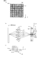
- FIG. 2A is a diagram illustrating an example of the arrangement of microlenses and image pickup devices
- FIG. 2A shows the arrangement of microlenses in the xy plane
- FIG. 2B is a photographic lens, microlens, and image pickup device in the optical axis direction
- FIG. 2C is a diagram showing the arrangement of the imaging pixels on one pixel array.
- FIG. 3A is a diagram for explaining the relationship between the size of a block and the number of viewpoints.
- FIG. 3A shows the arrangement of imaging pixels on one pixel array
- FIG. 3B shows the image data of five viewpoints to be generated. It is a figure which shows an example.
- FIG. 4A is a diagram for explaining the relationship between the size of a block and the number of viewpoints.
- FIG. 4A shows the arrangement relationship between imaging pixels and blocks in one pixel array
- FIG. 4B shows the generated four viewpoints. It is a figure which shows an example of image data.
- FIG. 5A is a diagram for explaining the principle when no parallax occurs between multi-viewpoint images.
- FIG. 5A shows a light beam when generating five viewpoint images
- FIG. Is an enlarged view in the vicinity of the focal plane
- FIG. 5C is an enlarged view of FIG. 5B in the vicinity of the microlens array and the image sensor.
- FIGS. 6A and 6B are views for explaining the principle when no parallax occurs between multi-viewpoint images, FIG.
- FIGS. 7A and 7B are diagrams for explaining the principle when parallax occurs between multi-viewpoint images.
- FIG. 7A shows a viewpoint image corresponding to viewpoint image data
- FIG. 7B shows a state of a light beam incident on an image sensor.
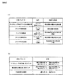
- FIG. 8A is a diagram illustrating an example of a variable parameter and a fixed parameter.
- FIG. 8A illustrates a variable parameter and characteristics that can be controlled by the variable parameter
- FIG. 8B illustrates an example of a fixed parameter.
- FIGS. 9A and 9B are diagrams illustrating calculation processing when generating a multi-viewpoint image.
- FIG. 9A and 9B are diagrams illustrating calculation processing when generating a multi-viewpoint image.
- FIG. 9A illustrates a coordinate system of a microlens in the xy plane
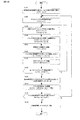
- FIG. 9B illustrates a coordinate system of an image sensor in the xy plane. It is a flowchart explaining the process of the digital camera in 1st Embodiment.
- FIG. 11A is a diagram illustrating an example of a configuration of a display of a digital camera in the embodiment
- FIG. 11A illustrates an example of a lenticular lens
- FIG. 11B illustrates a relationship between the display and a light beam in the xz plane.
- FIG. 13 (a) shows arrangement
- FIG.13 (b) is shown.
- FIG. 13C schematically shows the movement of the block according to the calculation result.
- FIG. 13C shows the arrangement of the microlens and the image sensor on the xy plane when the block is generalized. It is a flowchart explaining the process of the digital camera in 2nd Embodiment. It is a figure explaining the structure of the digital camera in 3rd Embodiment.
- the digital camera according to the present embodiment is configured to be able to generate images of a plurality of viewpoints (parallax) numbers for one object scene.
- This digital camera can create a multi-viewpoint image according to the user's selection by selecting the number of viewpoints desired by the user, parallax, viewpoint change direction, depth of field, and the like. Details will be described below.
- FIG. 1 is a diagram showing a configuration of a digital camera according to the first embodiment.
- the digital camera 1 is configured so that an interchangeable lens 2 having a photographing lens L1 can be attached and detached.
- the digital camera 1 includes an imaging unit 100, a control circuit 101, an A / D conversion circuit 102, a memory 103, a drive unit 104, a memory card interface 107, an operation unit 108, a display 109, and an LCD drive circuit 110.
- the imaging unit 100 includes a microlens array 12 and an imaging element 13 in which a large number of microlenses 120 are arranged two-dimensionally.
- the z-axis is set to be parallel to the optical axis of the photographic lens L1
- the x-axis and the y-axis are set to be orthogonal to each other in a plane orthogonal to the z-axis.
- the photographing lens L1 is composed of a plurality of optical lens groups, and forms an image of a light flux from the object field in the vicinity of the focal plane.
- the taking lens L1 is represented by a single lens for convenience of explanation.
- the microlens array 12 and the image sensor 13 are arranged in order.
- the image sensor 13 is configured by a CCD or CMOS image sensor including a plurality of photoelectric conversion elements.
- the imaging element 13 captures a subject image formed on the imaging surface, and outputs a photoelectric conversion signal (image signal) corresponding to the subject image to the A / D conversion circuit 102 under the control of the driving unit 104.
- the details of the imaging unit 100 will be described later.
- the drive unit 104 outputs a timing signal to the image sensor 13 in accordance with a command from the control circuit 101, and controls the drive timing of the image sensor 13.
- the A / D conversion circuit 102 is a circuit that performs analog processing on the image signal output from the image sensor 13 and then converts it to a digital image signal. Based on the control program, the control circuit 101 performs a predetermined calculation using signals input from each unit constituting the digital camera 1 and sends a control signal to each unit of the digital camera 1 to control the photographing operation. .
- the control circuit 101 functionally includes an image processing unit 105 and a calculation unit 106.
- the image processing 105 performs various image processing on the image signal digitally converted by the A / D conversion circuit 102 to generate image data. Then, the image processing unit 105 performs JPEG compression processing on the generated image data and records it in the memory card 107a in a format such as EXIF.
- the calculation unit 106 performs calculation processing for various image processing performed by the image processing unit 105 described above.
- the memory 103 is used to temporarily store the image signal digitally converted by the A / D conversion circuit 102, and data during or after the image processing, image compression processing, and display image data creation processing. It is a volatile storage medium.
- the memory card interface 107 is an interface to which the memory card 107a can be attached and detached.
- the memory card interface 107 is an interface circuit that writes image data to the memory card 107a and reads image data recorded on the memory card 107a under the control of the control circuit 101.
- the memory card 107a is a semiconductor memory card such as a compact flash (registered trademark) or an SD card.
- the LCD drive circuit 110 is a circuit that drives the display 109 based on a command from the control circuit 101.
- the display 109 is composed of, for example, a liquid crystal or the like, and displays display data created by the control circuit 101 based on image data recorded on the memory card 107a in the reproduction mode.
- the display 109 displays a menu screen for setting various operations of the digital camera 1. Details of the LCD drive circuit 110 and the display 109 will be described later.
- the operation unit 108 receives a user operation and outputs various operation signals corresponding to the operation content to the control circuit 101.
- the operation unit 108 includes a power button, a release button, a mode selection button, other setting menu display switching buttons, a setting menu determination button, and the like.
- the mode selection button is used when an operation for switching the operation of the digital camera 1 between the photographing mode and the reproduction mode is performed.
- the digital camera 1 also includes a multi-viewpoint image generation mode for shooting images with a plurality of viewpoints (multi-viewpoint images) as a shooting mode.
- the multi-viewpoint image generation mode is configured to allow the user to select viewpoint conditions such as the number of viewpoints, parallax, viewpoint change direction, depth of field, and the like of an image captured by the user. Selection of viewpoint conditions in the multi-viewpoint image generation mode is performed by operating the operation unit 108 from the above-described menu screen.
- the imaging unit 100 includes the microlens array 12 and the imaging element 13 as described above.
- the microlens array 12 includes a plurality of microlenses 120 arranged in a two-dimensional manner.
- a pixel array 130 that receives light that has passed through each of the microlenses 120 is arranged in an arrangement pattern corresponding to the microlens 120.
- Each pixel array 130 includes a plurality of photoelectric conversion elements 131 (hereinafter referred to as imaging pixels 131) arranged in a two-dimensional manner.
- FIG. 2 shows an example of the arrangement of the microlens 120 and the image sensor 13.
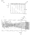
- FIG. 2A is a diagram illustrating an example of the arrangement of the microlens 120 and the imaging pixels 131 of the imaging element 13 in a direction (xy plane) orthogonal to the optical axis direction of the photographing lens L1.
- the microlens array 12 shown in FIG. 2A six microlenses 120 in the x-axis direction and six microlenses 120 in the y-axis direction, that is, 6 ⁇ 6 microlenses 120 are arranged.
- One microlens 120 is provided with one pixel array 130 correspondingly.
- Each pixel array 130 includes, for example, five imaging pixels 131 in the x-axis direction and five imaging pixels 131 in the y-axis direction, that is, 5 ⁇ 5 imaging pixels 131. That is, 5 ⁇ 5 imaging pixels 131 are arranged for one microlens 120. As a result, in the present embodiment, the imaging element 13 has 30 ⁇ 30 imaging pixels 131.
- FIG. 2B is a diagram for explaining the positional relationship among the photographing lens L1, the microlens 120, and the imaging element 13 in the optical axis direction (z-axis direction) of the photographing lens L1.
- the microlens 120 is arranged at a focal position (imaging plane) of the photographing lens L1 that captures an image of the subject (object plane), that is, a position conjugate with the object plane.
- the image sensor 13 is disposed at a position separated by the focal length of the microlens 120.
- the imaging surface of the imaging element 13 is conjugate with the photographing lens L1.
- FIG. 2B shows a case where the photographing lens L1 is focused on the object plane, that is, a case where a light beam from the photographing lens L1 is imaged on the microlens 120.
- the region occupied by the projection image on the pupil plane of the photographing lens L1 by the microlens 120 corresponding to the imaging pixel 131ai is a partial region P1 on the pupil of the photographing lens L1.
- the partial areas P2, P3,... correspond to the imaging pixels 131bi, 131ci,.
- On the pupil of the photographing lens L1 are transmitted through the microlenses and are incident on the imaging pixels 131ai, 131bi, 131ci,. .
- FIG. 1 the region occupied by the projection image on the pupil plane of the photographing lens L1 by the microlens 120 corresponding to the imaging pixel 131ai.
- the light beams r1 to r5 incident on the microlens 120 disposed on the optical axis of the photographing lens L1 are shown as representatives, but the microbeams provided at positions away from the optical axis are shown.
- the light beams r 1 to r 5 are incident on the lens 120 and guided to the corresponding imaging pixel 131.
- the partial areas P1, P2, P3,... Actually exist two-dimensionally, that is, in the y-axis direction, but only the arrangement in the x-axis direction is considered here for the sake of simplicity.
- FIG. 2C shows the positional relationship of the imaging pixels 131ai to 131di on one pixel array 130i.
- the partial regions P1 to P5 of the photographing lens L1 in the x-axis direction are taken as an example, so that the light beams r1 to r5 are respectively incident on the imaging pixels 131ai to 131di arranged side by side in the x-axis direction.
- each imaging pixel 131ai, 131bi, 131ci, ... outputs the image signal ai, bi, ci, ..., respectively.
- the image processing unit 105 of the digital camera 1 performs processing for generating a multi-viewpoint (multi-parallax) image using the image signal output from the imaging unit 100 configured as described above. Further, the LCD drive circuit 110 and the display device 109 of the digital camera 1 according to the present embodiment are configured to be able to display the generated multi-viewpoint (multi-parallax) image as a stereoscopic image (3D image).
- a multi-viewpoint (multi-parallax) image generation principle (B) a multi-viewpoint image generation principle, (C) a multi-viewpoint image generation process, and (D) stereoscopic display will be described.
- A Generation Principle of Multi-viewpoint (Multi-Parallax) Image
- the position and direction of the light beam from the subject are detected independently.
- the direction of the viewpoint is detected according to the number of imaging pixels 131 provided corresponding to one microlens 120.
- the image processing unit 105 generates image data for each image signal corresponding to the light beam r that has passed through each partial region P.
- the image processing unit 105 generates the same number of image data as the number of partial regions P having different viewpoints for the same subject, that is, the same number as the number of imaging pixels 131 included in one pixel array 130.
- FIG. 2A when 5 ⁇ 5 imaging pixels 131 are arranged for one microlens 120, 5 ⁇ 5 viewpoints can be detected.
- the unit 105 generates 5 ⁇ 5 image data with different viewpoints.
- the image processing unit 105 divides an area defined by one pixel array 130 into a plurality of extraction areas (for example, rectangular areas), and uses pixel signals output from the plurality of imaging pixels 131 included in the extraction area. To generate image data.
- the image processing unit 105 generates image data with the same number of viewpoints as the number of extraction regions.
- the same number of partial areas P as the number of extraction areas are divided by the pupil plane of the photographic lens L1, and the image processing unit 105 performs image signal corresponding to the luminous flux r that has passed through each partial area P.
- the extraction area is called a block.
- the block size is configured to be set by performing selection and setting processing by the user using the operation unit 108 on the menu screen. Details of the setting process will be described later.
- FIG. 3 shows a case where the size of the block Blo is set to 1 by the user, that is, a case where one imaging pixel 131 is included in one block Blo.
- FIG. 3A shows one pixel array 130 i of the plurality of pixel arrays 130 included in the image sensor 13 as an example.
- the image processing unit 15 extracts the image signal ai output from the imaging pixel 131ai included in the pixel array 130i illustrated in FIG. 3A from the image signal output from the imaging element 13. Further, the image processing unit 105 extracts the image signal a output from each imaging pixel 131 a of all the pixel arrays 130 included in the imaging element 13. Then, the image processing unit 105 generates one image data Im_a using all the extracted image signals a. Similarly, the image processing unit 105 uses the image signals b,..., E output from the respective imaging pixels 131b,. , Im_e. As a result, as shown in FIG. 3B, the image processing unit 105 generates five (5 viewpoints) image data Im_a, Im_b,... Im_e.
- FIG. 4 also shows only the number of viewpoints in the x-axis direction for convenience of explanation, as in FIG. FIG. 4A illustrates one pixel array 130 i of the plurality of pixel arrays 130 included in the image sensor 13 as an example.
- the block Blo_bi vertical line area in FIG. 4A
- Blo_ci dot area in FIG. 4A
- Blo_di horizontal line area in FIG. 4A
- FIG. 4A FIG. 4A
- the image processing unit 15 adds the image signals output from 6 (2 ⁇ 3) imaging pixels 131 included in the block Blo_ai of the pixel array 130 i from the image signals output from the imaging element 13. Then, one image signal ai is extracted. Further, the image processing unit 105 extracts the image signal a output from the imaging pixels 131 in each block Blo_a of all the pixel arrays 130 included in the imaging element 13. Then, the image processing unit 105 generates one image data Im_a using all the extracted image signals a. Similarly, the image processing unit 105 performs the same processing on the output from the imaging pixels 131 in each block Blo_b,..., Blo_di included in each pixel array 130 to perform image data Im_b,. Im_d is generated. As a result, as shown in FIG. 4B, the image processing unit 105 generates four (four viewpoints) image data Im_a, Im_b,... Im_d.
- each pixel of the image sensor 13 (that is, the size of the block Blo) defines the size of the partial region P of the photographing lens L1 that is conjugate with the image sensor 13, that is, the size (diameter) of the light beam. become. Therefore, the size of the set block Blo corresponds to the F value of the photographic lens L1, and the F value increases as the size of the block Blo decreases.
- the image processing unit 105 is output from one imaging pixel 131 to one microlens 120.
- Five image data Im_a to Im_e are generated based on the image signal. Therefore, when the size of the block Blo is set to 1, the F value increases, so that the depth of field of the image corresponding to each of the generated image data Im_a to Im_e becomes deep.
- the image processing unit 105 uses six imaging pixels 131 for one microlens 120. Image data is generated based on the output image signal. Since the partial area P of the photographing lens L1 in this case has a size six times larger than the partial area P of the photographing lens L1 in the case of FIG. 3, the luminous flux incident on the imaging pixel 131 in the block Blo is 6 Double the size (diameter). Therefore, when the size of the block Blo is set to 2 ⁇ 3, the F value becomes small, so that the depth of field of the image corresponding to each of the generated image data Im_a to Im_d becomes shallow.
- the viewpoint movement direction has been described as the x-axis direction.
- the viewpoint may move in the y-axis direction or in the two-dimensional direction on the xy plane.
- the shape of the block Blo is not limited to a rectangle.
- FIG. 5A is a diagram illustrating the light beams r1 to r5 when five viewpoint images are generated on the imaging side.
- FIG. 5B is an enlarged view of the light beams r1 to r5 in the vicinity of the photographing lens L1 and the focal plane (imaging plane) among the light beams r1 to r5 shown in FIG.
- FIG. 5C is an enlarged view of the light beams in the vicinity of the microlens array 12 and the imaging element 13 among the light beams r1 to r5 illustrated in FIG.
- the positions of the five viewpoints are the same as those of the imaging pixels 131ai to 131ei shown in FIGS.
- the light rays incident on each of the imaging pixels 131ai to 131ei provided corresponding to one microlens 120 intersect at the same point on the object plane Q1. Therefore, no parallax occurs on the image corresponding to each of the viewpoint image data Im_a to Im_e for the subject existing on the object plane Q1.
- the light beams r1 to r5 that intersect at the surface Q2 deviated from the object surface Q1 are guided to different microlenses 120.
- parallax occurs on the images corresponding to the viewpoint image data Im_a to Im_e.
- a case where parallax occurs and a case where parallax does not occur will be described in detail.
- FIG. 6A shows viewpoint images Ai to Ei corresponding to five viewpoint image data Im_a to Im_e generated by photographing an image of the subject “A” formed on the focal plane. That is, the viewpoint images Ai to Ei correspond to the image signals output from the imaging pixels 131ai to 131ei, respectively.
- Light beam r1 ⁇ r5 forming the formed image to the position of X5, respectively incident on the imaging pixel 131a5 ⁇ 131e5 through the microlens 120 5. Further, the light beam r1 ⁇ r5 forming the image formed at the position of X6, respectively incident on the imaging pixel 131a6 ⁇ 131e6 through the microlens 120 6. That is, the imaging pixels 131a1, 131a2, 131a3,... On the imaging element 13 receive the light beam r1 and output an image signal. As a result, the imaging pixels 131a1, 131a2,... Capture images of the positions X1, X2,.
- the imaging pixels 131b1, 131b2,... Receive the light beam r2, the imaging pixels 131c1, 131c2,... Receive the light beam r3, and the imaging pixels 131d1, 131d2,.
- the imaging pixels 131e1, 131e2,... Receive the light beam r5.
- images captured by the imaging pixels 131a1, 131a2,..., Images captured by the imaging pixels 131b1, 131b2,..., Images captured by the imaging pixels 131c1, 131c2,. ,... And the images captured by the imaging pixels 131e1, 131e2,... Are images at positions X1, X2,. Therefore, as shown in FIG. 6 (a), the five viewpoint images Ai to Ei generated based on the respective image signals output from the imaging pixels 131ai to 131ei are the same image, so that no parallax occurs. .
- FIG. 7A shows five viewpoint images Ai to Ei generated by photographing an image of the subject “A” formed on a plane different from the focal plane.
- the viewpoint images Ai to Ei correspond to the image signals output from the imaging pixels 131ai to 131ei, respectively.
- the light beam r1 is directed to the imaging pixel 131a4
- the light beam r2 is directed to the imaging pixel 131b5
- the light flux r3 is directed to the imaging pixel 131c6, and the light beam r4 is captured to the imaging pixel.
- the light beam r5 enters the imaging pixel 131e8 to 131d7.
- each of the light beams r1 to r5 that form images formed at different positions enters the image sensor 13 via different microlenses 120.
- the imaging pixels 131a1, 131a2, 131a3,... On the imaging element 13 receive the light beam r1 and output an image signal. That is, the imaging pixels 131a1, 131a2, 131a3,... Capture images of positions X3, X4, X5,. Further, since the imaging pixels 131b1, 131b2, 131b3,... On the imaging element 13 receive the light beam r2, the images at the positions X2, X3, X4,. Similarly, the imaging pixels 131c1, 131c2, 131c3,... Receive the light beam r3 and capture images at positions X1, X2, X3,..., And the imaging pixels 131d1, 131d2, 131d3,. , And images of positions X0 (not shown), X1, X2... Are taken, and the imaging pixels 131e1, 131e2, 131e3,. ), X0 (not shown), X1,...
- the multi-viewpoint (multi-parallax) image generation processing by the digital camera 1 in the first embodiment that is, the operation of the digital camera 1 when the multi-viewpoint image generation mode is set.
- the multi-viewpoint image generation mode is set by the control circuit 101 when the multi-viewpoint image generation mode is selected according to the operation of the mode selection button by the user and an operation signal is input from the operation unit 108.
- the characteristics of the viewpoint image that is, the three-dimensional image
- the selectable characteristics include the direction of viewpoint change, the number of viewpoints, the amount of viewpoint change, and the number of pixels for viewpoint generation (the size of block Bl). These characteristics are set when the user performs a selection operation using the operation unit 108 on the menu screen displayed on the display 109 described above.
- the calculation unit 106 uses a parameter corresponding to the above characteristic as a variable parameter for calculation processing when generating viewpoint image data.
- Fig. 8 (a) shows various variable parameters and the characteristics that can be controlled by the variable parameters.
- “Number of pixels (imaging pixels 131) u, v” in the block shown in FIG. 8A is a variable parameter for determining the size of the block Blo, and depends on the number of pixels in the set block Blo. As described above, the depth of field of the viewpoint image is determined. Note that u represents the number of pixels in the x-axis direction in the block Blo, and v represents the number of pixels in the y-axis direction in the block Blo.
- the number of times the block moves Kx, Ky is a variable parameter for determining the number of viewpoints of the multi-viewpoint image.
- the image processing unit 105 sets the same number of different blocks Blo as the set number of times Kx and Ky on the pixel array 130, and extracts an image signal from the imaging pixels 131 included in each block Blo. As shown in FIGS. 3 and 4, if the block Bl moves 5 times, an image of 5 viewpoints is generated, and if the block Bl moves 4 times, an image of 4 viewpoints is generated.
- Block movement amounts Sx, Sy are variable parameters for determining the amount of change in viewpoint between a plurality of viewpoint images. The larger the amount that the block Blo moves, the greater the parallax that occurs between the viewpoint images.
- the image processing unit 105 extracts an image signal from the blocks Bl arranged on the pixel array 130 at position intervals corresponding to the set movement amounts Sx and Sy.
- “Block movement direction Arctan (Sy / Sx)” is a variable parameter for determining the direction of the viewpoint change of the viewpoint image.
- the image processing unit 105 extracts an image signal from the block Blo set on the pixel array 130 along the selected moving direction. In the example described with reference to FIGS. 3 and 4, the case where the x-axis direction is set as the movement direction is shown.
- “Block initial positions U0, V0” are variable parameters for determining the initial position of the viewpoint of the viewpoint image.
- the resolutions M and N are set as fixed parameters. These fixed parameters are values determined depending on the structure of the microlens 120 and the image sensor 13.
- the values of the variable parameter and the fixed parameter are as follows.
- Number of arrangement of microlenses 120 in the x-axis direction M 6
- Number of arrangement of microlenses 120 in the y-axis direction N 6
- Cx 30
- Cy 30
- the values of the variable parameter and the fixed parameter are as follows.
- Number of arrangement of microlenses 120 in the x-axis direction M 6
- Number of arrangement of microlenses 120 in the y-axis direction N 6
- Cx 30
- Cy 30
- the image processing unit 105 When the various parameters described above are set, the image processing unit 105 generates a plurality of viewpoint image data using an image signal acquired by photographing one subject and stored in the memory 103. As described above, the image processing unit 105 is output from the imaging pixels 131 included in the set block Bl among the image signals output from the imaging pixels 131 in the pixel array 130 corresponding to one microlens 120. The extracted pixel signal is extracted. Then, the image processing unit 105 extracts pixel signals in the same manner for all the pixel arrays 130, and generates one viewpoint image data Im using the plurality of extracted pixel signals.
- the image processing unit 105 generates a plurality of viewpoint image data Im by performing the above-described processing by the number of movements Kx and Ky of the set block Blo while moving the set block Blo by the movement amounts Sx and Sy. To do. At this time, the image processing unit 105 extracts an image signal based on the calculation result by the calculation unit 106. That is, the calculation unit 106 determines an image signal that the image processing unit 105 extracts to generate the viewpoint image data Im.
- FIG. 9A shows a coordinate system (m, n) of the microlens array 12 in the xy plane.
- FIG. 9A 0 ⁇ m ⁇ 6, 0 ⁇ n ⁇ 6.
- FIG. 9B shows a coordinate system (i, j) of the image sensor 13 in the xy plane.
- a pixel value from the image pickup pixel 131 arranged at (i, j), that is, an image signal is represented by I (i, j).
- the coefficient p is a fixed parameter indicating the arrangement pitch of the microlenses 120 in the x-axis direction as described above
- the coefficient q is a fixed parameter indicating the arrangement pitch of the microlenses 120 in the y-axis direction.
- the calculation unit 106 calculates the initial position (lower left corner) (X, Y) of the block in the microlens 120 using the following equation (2).
- the coefficient s is a fixed parameter indicating the arrangement pitch of the imaging pixels 131 in the x-axis direction
- the coefficient t is a fixed parameter indicating the arrangement pitch of the imaging pixels 131 in the y-axis direction.
- the coefficient Nx is a parameter indicating the number of viewpoint image data Im generated in the x-axis direction, and 0 ⁇ Nx ⁇ Kx.
- the coefficient Ny is a parameter indicating the number of viewpoint image data Im generated in the y-axis direction, and 0 ⁇ Ny ⁇ Ky.
- the initial position (X, Y) of the block Blo is expressed by the following equation (2) ′.
- the coefficient v is the number of imaging pixels 131 in the y-axis direction included in the block Blo as described above.
- the image processing unit 105 extracts the image signal I using the initial position of the block Blo calculated by the above equation (3). That is, the image processing unit 105 uses the image signal corresponding to the initial position (i, j) calculated by Expression (3) as a reference, and the sum of the image signals included in the block Blo (block signal Ib (i, j )) Is calculated. In this case, the image processing unit 105 calculates the block signal Ib (i, j) using the following equation (4).
- the block signal Ib (i, j) has a value represented by the following expression (4) ′.
- the block signal Ib (i, j) has a value represented by the following expression (4) ′′.
- the image processing unit 105 generates one viewpoint image data Im using the block signal Ib (i, j) generated by performing the above processing on all the microlenses 120. That is, the image processing unit 105 adds each block signal Ib so that the block signal Ib (i, j) represents one pixel value in the viewpoint image data Im. Thereafter, the calculation unit 106 newly sets the initial position (i, j) of the block Bl when the block Bl is moved by the set movement direction (the movement amounts Sx and Sy set in Arctan (Sy / Sx)).
- the image processing unit 105 newly calculates a block signal Ib (i, j) using Expression (4) based on the newly calculated initial position (i, j) of the block Blo, One different viewpoint image data Im is generated, and the image processing unit 105 repeats the above process for the set number of movements Kx and Ky to generate a plurality of viewpoint image data Im.
- the image processing unit 105 generates a multi-viewpoint image file using the plurality of viewpoint image data Im generated as described above, and records it in the memory card 107a. Note that the image processing unit 105 may associate the generated viewpoint image data Im with each of the generated viewpoint image data Im and record them in the memory card 107a.
- step S101 the number of viewpoint images to be generated (Nx, Ny) is set to 0, which is an initial value, and the process proceeds to step S102.
- step S102 the values of m and n are set to 0 as the initial position of the microlens 120, and the process proceeds to step S103.
- step S103 the center position of the target microlens 120 is calculated using equation (1), and the process proceeds to step S104.
- step S104 using Equation (2), the initial position of the block Blo in the coordinate system of the microlens 120, that is, the coordinates of the lower left end is calculated, and the process proceeds to step S105.
- step S105 the coordinate value calculated in step S104 is converted into the coordinate system (i, j) of the image sensor 13 using equation (3), and the process proceeds to step S106.
- Step S106 the image signal output from the photoelectric conversion signal 131 included in the block is added using Expression (4) to generate the block signal Ib, and the process proceeds to Step S107.
- step S109 the block signals Ib generated for each pixel array 130 are combined to generate one viewpoint image data Im, and the process proceeds to step S110.
- step S111 it is determined whether viewpoint image data Im for the set number of viewpoints (Kx, Ky) has been generated.
- an affirmative determination is made in step S111 and the process proceeds to step S112.
- viewpoint image data Im having the set number of viewpoints has not been generated, a negative determination is made in step S1111 and the process returns to step S102.
- step S112 a multi-viewpoint image file is generated using the generated Kx ⁇ Ky viewpoint image data Im, recorded in the memory card 107a, and the process ends.
- the display device 109 includes a lenticular lens 150 having a plurality of convex lenses 151 having a shape obtained by cutting a cylindrical shape in the axial direction on the surface thereof. That is, the display 109 displays a plurality of viewpoint images as a stereoscopic image by a known lenticular method.
- the long sides of the individual convex lenses 151 of the lenticular lens 150 are arranged in the y-axis direction. In the following description, processing in the x-axis direction is mainly performed as a representative.
- FIG. 11B shows a cross-sectional view of the display 109 on the xz plane.
- Each convex lens 151 of the lenticular lens 150 condenses light from a plurality of pixel rows Co that constitutes the display unit 109 along the y-axis direction and guides it to the user.
- one convex lens 151a condenses the light emitted from the pixel columns Co1_1 to Co1_5 of the display 109.
- light from the pixel columns Co1_1, Co2_1, Co3_1,... formss an image at a point W1.
- light from the pixel columns Co1_2, Co2_2, Co3_2,... Is at the point W2, and light from the pixel columns Co1_3, Co2_3, Co3_3,.
- the right eye observes the image of the point W1, that is, the light from the pixel columns Co1_1, Co2_1, Co3_1,.
- the left eye observes the image of the point W2, that is, the light from the pixel columns Co1_2, Co2_2, Co3_2,.
- the right eye observes the image of the point W4 (light from the pixel columns Co1_4, Co2_4, Co3_4,...), And the left eye observes the image of the point W5 (pixel column). (Light from Co1_5, Co2_5, Co3_5,).
- the display device 109 may display a plurality of viewpoint images as a stereoscopic image by a parallax barrier method.
- a mask (barrier) having a plurality of elongated openings with long sides aligned in the y-axis direction may be disposed at a position where the lenticular lens 150 of FIG. 11 is disposed.
- FIG. Im5 A process for generating display data to be output to the display 109 capable of displaying a stereoscopic image as described above will be described using the conceptual diagram shown in FIG. Im5, Im2,..., Im5 are viewpoint image data corresponding to multi-viewpoint images with parallax (for example, five viewpoints) obtained by photographing the same object scene.
- the image processing unit 105 extracts the image data corresponding to the same pixel column Co1 from Im1, Im2,... create. Further, the image processing unit 105 extracts image data corresponding to the pixel column Co2 from each of the viewpoint image data Im1, Im2,... Im5, and creates one display image data Id2. Similarly, the image processing unit 105 generates display image data Id3 to Id5.
- the image processing unit 105 When each of the display image data Id1 to Id5 is created, the image processing unit 105 outputs the display image data Id1 to the LCD drive control unit 110, and corresponds to the display image data Id1 in Co1 of the display 109. Display an image. Similarly, the image processing unit 105 outputs display image data Id2 to Id5 to the LCD drive control unit 110, and displays images corresponding to the display image data Id2 to Id5 on Co2 to Co5 of the display unit 109, respectively. .
- an image corresponding to the viewpoint image data Im1 is observed at the point W1.
- the image corresponding to the viewpoint image data Im2 is observed at the point W2
- the image corresponding to the viewpoint image data Id3 is observed at the point W3
- the image corresponding to the viewpoint image data Im4 is observed at the point W4.
- An image corresponding to the data Im5 is observed at a point W5.
- the user located at H1 observes the point W1 with the right eye and observes the point W2 with the left eye.
- the user of H1 observes the image corresponding to the viewpoint image data Im1 with the right eye, and observes the image corresponding to the viewpoint image data Im2 with the left eye.
- There is parallax between the viewpoint image data Im1 and Im2 and the user observes images corresponding to the viewpoint image data Im1 and Im2 with different eyes.
- an image obtained by photographing the same scene is observed as a stereoscopic image by the user.
- the user When the user is located at H1, the user observes an image corresponding to the viewpoint image data Im4 with the right eye, and observes an image corresponding to the viewpoint image data Im5 with the left eye, thereby photographing the same scene. Observe the image as a stereoscopic image.
- a plurality of microlenses 120 are two-dimensionally arranged near the focal plane of the taking lens L1.
- the imaging device 13 includes a plurality of pixel arrays 130 arranged in a two-dimensional manner having a plurality of photoelectric conversion elements (imaging pixels) 131 for each of the plurality of microlenses 120.
- the imaging pixel 131 receives the light beam from the subject that has passed through the photographing lens L1 through the microlens 120 and outputs an image signal.
- the image processing unit 105 outputs a plurality of block signals Ib corresponding to each of a plurality of different partial regions P of the photographing lens L1 from the image signals output from the plurality of imaging pixels 131 included in each of the plurality of pixel arrays 130. Based on the extracted block signal Ib, a plurality of image data Im corresponding to each of the partial areas P is generated as viewpoint image data Im having different viewpoint positions. That is, the image processing unit 105 is a block signal Ib extracted from a different pixel array 130 among a plurality of block signals Ib extracted from each of the plurality of pixel arrays 130, and blocks corresponding to the same partial region P. The signal Ib is synthesized to generate one viewpoint image data Im.
- the operation unit 108 accepts an operation for selecting the number of viewpoints by the user.
- the image processing unit 105 extracts the block signal Ib of the number of viewpoints selected by the user's operation, and generates viewpoint image data Im.
- the digital camera 1 Since the digital camera 1 according to the present embodiment has the above-described configuration, it is possible to acquire viewpoint image data of the number of viewpoints desired by the user using one camera according to the characteristics of the display. Convenience is improved. Furthermore, as with normal single-lens reflex photography, the lens can be freely exchanged, and the focus adjustment function can be used to focus on an arbitrary position of the subject. In this case, the convergence and the focal position are always the same for changes in focal length such as lens replacement and zoom lens, and changes in the focal position of the subject. Images can be taken. In other words, it is possible to create a stereoscopic image with the subject focused on the front and back from an image captured by adjusting the focus in the same way as a normal camera, so the user can shoot using a normal camera. 3D images can be taken without feeling uncomfortable.
- the computing unit 106 calculates the same number of blocks Blo as the number of viewpoints selected by the user as an extraction region for extracting the block signal Ib, and sets each block on the pixel array 130. Then, the image processing unit 105 adds the image signal I output from the imaging pixel 131 included in the block Bl for each set block Bl and extracts the block signal Ib. Accordingly, since the viewpoint image data Im having the number of viewpoints desired by the user can be generated, stereoscopic image shooting according to characteristics of a monitor or the like for displaying a stereoscopic image can be performed with one camera.
- the operation unit 108 receives an operation by the user for selecting a parallax indicating the amount of change in viewpoint between the plurality of viewpoint image data Im.
- the calculation unit 106 sets the blocks Blo on the pixel array 130 at position intervals corresponding to the parallax selected by the user. That is, the calculation unit 106 calculates the movement amount of the block Bl.
- the image processing unit 105 extracts the block signal Ib for each block Blo at a plurality of positions, and generates the viewpoint image data Im. Therefore, since a stereoscopic image having a parallax desired by the user can be performed with one camera, convenience is improved.
- the operation unit 108 receives an operation by the user for selecting the depth of field of the image.
- the calculation 106 calculates and sets the size of the block Blo according to the depth of field selected by the user.
- the image processing unit 105 synthesizes a plurality of image signals I from the imaging pixels 131 included in the block Bl in accordance with the calculated size of the block Blo, and extracts them as one block signal Ib. Im was generated. Therefore, the depth of field desired by the user can be obtained as a stereoscopic image with a simple operation.
- the operation unit 108 receives an operation by the user for changing the viewpoint position in the two-dimensional direction.
- the calculation unit 106 calculates and sets directions for extracting the block Bl for the number of viewpoints according to the operation by the user.
- the image processing unit 105 generates the viewpoint image data Im by extracting the block signal Ib from the block Blo along the calculated direction. Accordingly, the viewpoint image data Im having different viewpoints in the direction desired by the user can be generated, so that one camera can shoot a three-dimensional image according to the characteristics of a monitor or the like that displays a three-dimensional image.
- the image processing unit 105 generates display image data Id based on the generated plurality of viewpoint image data Im, and causes the display 109 to display an image corresponding to the display image data Id as a stereoscopic image. did. Therefore, the user can immediately observe an image corresponding to the captured viewpoint image data as a stereoscopic image.
- Embodiment- A digital camera according to a second embodiment of the present invention will be described with reference to the drawings.
- the same components as those in the first embodiment are denoted by the same reference numerals, and differences will mainly be described. Points that are not particularly described are the same as those in the first embodiment.
- This embodiment is different from the first embodiment in that the size of one microlens 120 is not an integral multiple of the size of the imaging pixel 131.
- the calculation processing by the calculation unit 106 and the calculation processing of the block signal Ib by the image processing unit 105 are different from the case of the first embodiment.
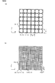
- FIG. 13 shows the size relationship between the microlens 120 and the imaging pixel 131 in the coordinate system (i, j) of the imaging device 13 on the xy plane.
- the diameter of the microlens 120 of the second embodiment in the direction parallel to the x-axis or y-axis direction is an integral multiple of the size of the imaging pixel 131. It is not. That is, in the x-axis direction, the x-axis direction of the microlens 120 includes a part of the imaging pixels 131u and 131v. Note that the cross-shaped index in FIG. 13 indicates the center position of the microlens 120.
- the block Blo has a size in which the area includes a part of each of the four imaging pixels 131a to 131d.
- the calculation unit 106 calculates a ratio (hereinafter referred to as occupancy ratio) that the area where the imaging pixel 131a and the block Bl overlap is occupied with respect to the entire area of the imaging pixel 131a.
- the image processing unit 105 adds the occupancy calculated by the calculation unit 106 to the image signal output from the imaging pixel 131a.
- the above processing is performed on the imaging pixels 131b to 131d included in the block Bl, and the image processing unit 105 adds the calculated image signals to calculate the block signal Ib of the block Bl.
- FIG. 13B shows a case where the size of the block Blo is generalized as u ⁇ v.
- the block Blo includes a part of each of the 14 imaging pixels 131a to 131n and the entire area of the 6 imaging pixels 131o to 131t.
- the image processing unit 105 interpolates the occupancy calculated by the calculation unit 106 by adding it to the image signals from the corresponding imaging pixels 131a to 131n. Calculate as a signal. Then, the image processing unit 105 calculates the block signal Ib by adding the calculated interpolation signals of the imaging pixels 131a to 131n and the image signals output from the imaging pixels 131o to 131t. That is, the image processing unit 105 calculates the block signal Ib by weighting the image signal according to the occupation ratio. Details will be described below.
- the coefficient p is a fixed parameter indicating the arrangement pitch of the microlenses 120 in the x-axis direction as described above
- the coefficient q is a fixed parameter indicating the arrangement pitch of the microlenses 120 in the y-axis direction.
- the calculation unit 106 calculates the initial position (lower left corner) (X, Y) of the block Bl in the microlens 120 using the following equation (6).
- the coefficient s is a fixed parameter indicating the arrangement pitch of the imaging pixels 131 in the x-axis direction
- the coefficient t is a fixed parameter indicating the arrangement pitch of the imaging pixels 131 in the y-axis direction.
- the coefficient Nx is a parameter indicating the number of viewpoint image data Im generated in the x-axis direction, and 0 ⁇ Nx ⁇ Kx.
- the coefficient Ny is a parameter indicating the number of viewpoint image data Im generated in the y-axis direction, and 0 ⁇ Ny ⁇ Ky.
- the values of a and b shown in Expression (7) are the amounts by which the lower left corner of the block Bl shown in FIG. 13B is shifted from the lower left corner of the imaging pixel 131s in the x-axis direction and the y-axis direction, respectively. Show. In other words, the values of a and b indicate the above-described occupation ratio.
- the image processing unit 105 extracts the image signal I using the initial position of the block Blo calculated by the above equation (7). That is, the image processing unit 105 uses the image signal corresponding to the initial position (i, j) calculated by Expression (7) as a reference, and the sum of the image signals included in the block Blo (block signal Ib (i, j )) Is calculated. In this case, the image processing unit 105 calculates the block signal Ib (i, j) using the following equation (8).
- Ib (i, j) (1-a) * (1-b) * I (i, j) + (1-a) * b * I (i + u, j) + a * b * I (i + u, j + v) + (1-a) ⁇ ⁇ I (i, j + 1) +... + I (i, j + v ⁇ 1) ⁇ + A ⁇ ⁇ I (i + u, j + 1) +... I (i + u, j + v ⁇ 1) ⁇ + (1-b) ⁇ ⁇ I (i + 1, j) +... + I (i + u ⁇ 1, j) ⁇ + B ⁇ ⁇ I (i + 1, j) +...
- the block signal Ib (i, j) of the block Blo shown in FIG. 13A has a value represented by the following equation (8) ′.
- Ib (i, j) (1-a) * (1-b) * I (i, j) + (1-a) * b * I (i, j + 1) + A ⁇ (1 ⁇ b) ⁇ I (i + 1, j) + a ⁇ b ⁇ I (i + 1, j + 1) (8) ′
- the image processing unit 105 blocks the block Blo at a position moved by the set movement amounts Sx and Sy.
- the signal Ib is calculated.
- FIG. 13C shows how the block Blo moves according to the calculation result of the calculation unit 106.
- the image processing unit 105 can calculate the block signal Ib even when the diameter of the microlens 120 is not an integral multiple of the size of the imaging pixel 131. Therefore, even when the movement amounts Sx and Sy of the block Blo are not integer multiples, the image processing unit 105 can calculate the block signal Ib at the position of the block Blo after movement. In other words, the movement amount of the block Blo can be set to an arbitrary real value desired by the user.
- step S201 the number of viewpoint images to be generated (Nx, Ny) is set to 0, which is an initial value, and the process proceeds to step S202.
- step S202 the values of m and n are set to 0 as the initial position of the microlens 120, and the process proceeds to step S203.
- step S203 the center position of the target microlens 120 is calculated using equation (5), and the process proceeds to step S204.
- step S204 using Equation (6), the initial position of the block Blo in the coordinate system of the microlens 120, that is, the coordinates of the lower left end is calculated, and the process proceeds to step S205.
- step S205 the coordinate value calculated in step S204 is converted into the coordinate system (i, j) of the image sensor 13 using equation (7), and the process proceeds to step S206.
- step S206 using the equation (8), the image signals output from the imaging pixels 131 included in the block Blo are added to generate the block signal Ib, and the process proceeds to step S207.
- step S207 movement to the next microlens
- step S212 generation and recording of a multi-viewpoint image file
- step S107 moving to the next microlens shown in FIG. 14
- step S112 multi-viewpoint image
- the image processing unit 105 determines the degree of overlapping with respect to the image signals output from the overlapping imaging pixels 131.
- the block signal Ib is extracted by performing weighting determined according to the above. Therefore, even if the installation accuracy of the imaging pixel 131 and the microlens 120 is low, a stereoscopic image desired by the user can be generated. Furthermore, since the size and movement amount of the block Bl are not restricted by the imaging pixel 131, it is possible to realize the viewpoint condition desired by the user.
- a digital camera according to a third embodiment of the present invention will be described with reference to the drawings.
- the same components as those in the first and second embodiments are denoted by the same reference numerals, and different points will be mainly described. Points that are not particularly described are the same as those in the first or second embodiment.
- the first and second points are configured in such a way that a multi-viewpoint (multi-parallax) image can be generated even when the user takes an image while holding the digital camera in a vertical position. Different from the embodiment.
- FIG. 15 shows a block diagram of a control system of the digital camera 1 according to the third embodiment.
- the posture sensor 300 is constituted by, for example, an inclination sensor or a gyro sensor, detects the direction of gravity of the digital camera 1, and outputs a detection signal to the control circuit 101.
- the control circuit 101 determines the attitude of the digital camera 1, that is, the horizontal position or vertical position of the digital camera 1 based on the input detection signal.
- the posture of the digital camera 1 determined by the detection signal from the posture sensor 300 when acquiring the image data is stored in the memory 103 in association with the image data as posture information.
- the control circuit 101 refers to the posture information stored in the memory 103 in association with the target image data.
- the calculation unit 106 sets fixed parameters (M, Cx, p, s) and variable parameters (U0, Kx, Sx, u) in the x-axis direction in the y-axis direction.
- the first and second implementations are regarded as set values, and the fixed parameters (N, Cy, q, t) and variable parameters (V0, Ky, Sy, v) in the y-axis direction are regarded as set values in the x-axis direction.
- the arithmetic processing described in the form is performed.
- the image processing unit 105 generates viewpoint image data Im having a different number of viewpoints in the y-axis direction.
- the attitude sensor 300 detects the attitude of the digital camera 1.
- the calculation unit 106 blocks so that the viewpoint position is in the y-axis direction on the image sensor 13, that is, different from horizontal position shooting. Set the movement direction of Blo.
- the image processing unit 105 generates the viewpoint image data Im by extracting the block signal Ib along the set direction, that is, the y-axis direction. Accordingly, since a stereoscopic image can be generated with either one of the vertical position shooting and the horizontal position shooting with one camera, convenience is improved.
- the digital camera 1 according to the first to third embodiments described above can be modified as follows.
- An external display device different from the digital camera 1 is used instead of the one that causes the display 109 to display the image corresponding to the display image data Id generated by the image processing unit 105 using the multi-viewpoint image data.
- You may display on the monitor with which (for example, a personal computer, television, etc.) is provided.
- the external display device reads the multi-viewpoint image file generated by the digital camera 1 and recorded on the memory card 107a. Then, the display device performs the same processing as the image processing unit 105 using the viewpoint image data Im in the read multi-viewpoint image file, generates display image data Id, and outputs it to the monitor.
- the monitor included in the display device needs to be configured to display a stereoscopic image by a lenticular method, a parallax barrier method, or the like, similarly to the display device 109 of the embodiment.
- the display device reads the multi-viewpoint image file from the digital camera 1, for example, an interface such as a LAN cable or wireless communication may be used.
- the image data generated by the digital camera 1 may be read by an external display device, and the display device may perform the same processing as the image processing unit 105 to generate the viewpoint image data Im.
- viewpoint image data Im having a predetermined number of viewpoints is generated in advance. May be.
- the image processing unit 105 uses the image signal stored in the memory 103 to generate 100 viewpoint image data Im so as to obtain 100 viewpoint images, for example, and stores the generated viewpoint image data Im in the memory 103. Then, the image processing unit 105 selects the same number of viewpoint image data Im as the number of viewpoints selected by the user according to the variable parameter set in the memory 103 and set from among the 100 viewpoint image data Im.
- a viewpoint image file is generated and recorded in the memory card 107a.
- the present invention is not limited to the above-described embodiment as long as the characteristics of the present invention are not impaired, and other forms conceivable within the scope of the technical idea of the present invention are also within the scope of the present invention. included.
- the embodiments and modifications used in the description may be configured by appropriately combining them.
Landscapes
- Engineering & Computer Science (AREA)
- Multimedia (AREA)
- Signal Processing (AREA)
- Physics & Mathematics (AREA)
- General Physics & Mathematics (AREA)
- Optics & Photonics (AREA)
- Testing, Inspecting, Measuring Of Stereoscopic Televisions And Televisions (AREA)
- Studio Devices (AREA)
- Cameras In General (AREA)
- Stereoscopic And Panoramic Photography (AREA)
- Transforming Light Signals Into Electric Signals (AREA)
Abstract
Description
本発明の第2の態様によれば、第1の態様による撮像装置において、生成部は、複数の素子群のそれぞれから抽出した複数の領域画像信号のうち、異なる素子群から抽出された領域画像信号であって、同一の部分領域に対応する領域画像信号を合成して1つの視点画像データを生成することが好ましい。
本発明の第3の態様によれば、第1または第2の態様による撮像装置において、領域画像信号を抽出するための抽出領域を設定する設定部を備え、設定部は、選択された視点数と同数の抽出領域を、素子群の異なる位置に設定し、生成部は、設定部により設定された抽出領域ごとに領域画像信号を抽出することが好ましい。
本発明の第4の態様によれば、第3の態様による撮像装置において、受付部は、複数の視点画像データ間における視点の変化量を示す視差を選択する視差選択操作を受け付け、設定部は、視差選択操作によって選択された視差に応じた位置間隔で前出領域を設定し、生成部は、位置間隔ごとに抽出領域から領域画像信号を抽出して、視点画像データを生成することが好ましい。
本発明の第5の態様によれば、第3または第4の態様による撮像装置において、受付部は、画像の被写界深度を選択する深度選択操作を受け付け、設定部は、深度選択操作によって選択された被写界深度に応じて抽出領域の大きさを設定し、生成部は、設定された抽出領域の大きさに応じて、複数の画像信号を合成して1つの領域画像信号として抽出し、視点画像データを生成することが好ましい。
本発明の第6の態様によれば、第3乃至第5のいずれかの態様による撮像装置において、受付部は、視点の位置を二次元方向に異ならせる視点位置選択操作をさらに受け付け、設定部は、視点位置選択操作に応じて視点数と同数の抽出領域を抽出する方向を設定し、生成部は、設定部により設定された方向に沿って領域画像信号を抽出して視点画像データを生成することが好ましい。
本発明の第7の態様によれば、第3乃至第6のいずれかの態様による撮像装置において、生成部は、設定部により設定された抽出領域が1つの光電変換素子のうちの一部と重複する場合には、重複する光電変換素子から出力された画像信号に対して重複する割合に応じて決まる重み付けを行って領域画像信号として抽出することが好ましい。
本発明の第8の態様によれば、第3乃至第7のいずれかの態様による撮像装置において、撮像装置の姿勢を検出する姿勢検出部を備え、設定部は、姿勢検出部により検出された姿勢に応じて視点の位置が異なるように視点数と同数の抽出領域を抽出する方向を設定し、生成部は、設定部により設定された方向に沿って領域画像信号を抽出して視点画像データを生成することが好ましい。
本発明の第9の態様によれば、第1乃至第8のいずれかの態様による撮像装置において、生成部により生成された複数の視点画像データに基づいて表示用画像データを生成し、表示用画像データに対応する画像を立体画像として表示器に表示させる表示制御部をさらに備えることが好ましい。
本実施の形態のデジタルカメラは、1つの被写界について複数の視点(視差)数の画像が生成可能に構成されている。このデジタルカメラは、ユーザが所望する視点数、視差、視点変化の方向、被写界深度等を選択すると、ユーザの選択に応じた多視点の画像を作成することができる。以下、詳細に説明する。
撮像ユニット100に含まれる各撮像画素131から出力される画像信号を用いて、被写体からの光束の位置と方向とがそれぞれ独立に検出される。被写体からの光束の位置はマイクロレンズ120の数に応じて検出できる。そのため、画像信号に基づいて生成される画像データの画素数、すなわち解像度はマイクロレンズ120の数によって制限されることになる。図2(a)に示すように、マイクロレンズアレイ12が6×6個のマイクロレンズ120を有している場合には、画像データの解像度は36(=6×6)となる。
上記のようにして生成された複数の視点画像のそれぞれについて視差が生じる場合と生じない場合について説明する。まず、図5を用いて、複数の視点画像のそれぞれについて視差が生じない場合について説明する。図5(a)は撮像側で5つの視点画像を生成する場合の光束r1~r5を説明する図である。図5(b)は、図5(a)に示す光束r1~r5のうち、撮影レンズL1と焦点面(結像面)付近での光束r1~r5を拡大して示す図である。さらに、図5(c)は、図5(b)に示す光束r1~r5のうち、マイクロレンズアレイ12および撮像素子13付近での光束を拡大して示す図である。
図6を参照しながら、複数の視点画像のそれぞれについて視差が生じない場合について説明する。図6(a)は、焦点面に結像した被写体「A」の像を撮影して生成された5つの視点画像データIm_a~Im_eに対応する視点画像Ai~Eiを示す。すなわち、視点画像Ai~Eiは、撮像画素131ai~131eiから出力された画像信号にそれぞれ対応している。図6(b)は撮像素子13に入射する光束の様子を示す。図6(b)では、紙面の上下方向をz軸方向とし、z=0をマイクロレンズ120の面、すなわち焦点面に設定している。焦点面(z=0)に結像した被写体「A」の像の位置をX1~X9として表す。
図7を参照しながら、複数の視点画像のそれぞれについて視差が生じない場合について説明する。図7(a)は、焦点面とは異なる面に結像した被写体「A」の像を撮影して生成された5つの視点画像Ai~Eiを示す。図6(a)の場合と同様に、視点画像Ai~Eiは、撮像画素131ai~131eiから出力された画像信号にそれぞれ対応している。図7(b)は撮像素子13に入射する光束の様子を示す。図7(b)においても、紙面の上下方向をz軸方向とし、z=0をマイクロレンズ120の面、すなわち焦点面に設定している。焦点面とは異なる面(z=h1)に結像した被写体「A」の像の位置をX1~X9として表す。
以下、第1の実施の形態におけるデジタルカメラ1による多視点(多視差)画像の生成処理、すなわち多視点画像生成モードが設定された場合のデジタルカメラ1の動作について説明する。なお、多視点画像生成モードは、ユーザによるモード選択ボタンの操作に応じて多視点画像生成モードが選択され、操作部108から操作信号が入力されると、制御回路101により設定される。
マイクロレンズ120のx軸方向の配列数M=6
マイクロレンズ120のy軸方向の配列数N=6
撮像素子13のx軸方向の画素数Cx=30
撮像素子13のy軸方向の画素数Cy=30
ブロックの初期位置U0=0、V0=0
ブロックの移動する回数Kx=5、Ky=1
ブロックの移動量Sx=1、Sy=0
ブロック内の画素数u=1、v=1
なお、この場合の視点画像の解像度は36(=6×6=M×N)である。
マイクロレンズ120のx軸方向の配列数M=6
マイクロレンズ120のy軸方向の配列数N=6
撮像素子13のx軸方向の画素数Cx=30
撮像素子13のy軸方向の画素数Cy=30
ブロックの初期位置U0=0、V0=0
ブロックの移動する回数Kx=4、Ky=1
ブロックの移動量Sx=1、Sy=0
ブロック内の画素数u=2、v=3
なお、この場合の視点画像の解像度は36(=6×6=M×N)である。
図9(a)にxy平面におけるマイクロレンズアレイ12の座標系(m,n)を示す。この座標系では、図の左下端のマイクロレンズ120の位置を(m,n)=(0,0)として示す。なお、図9(a)においては、0≦m<6,0≦n<6である。さらに、図9(b)にxy平面における撮像素子13の座標系(i,j)を示す。図9(b)の撮像素子13の座標系において、(i,j)に配置された撮像画素131からの画素値、すなわち画像信号をI(i,j)で表す。
X0=mp+p/2
Y0=nq+q/2 ・・・(1)
X=X0+U0+s・Nx・Sx
Y=Y0+V0+t・Ny・Sy ・・・(2)
X=mp+s・Nx
Y=(n+1/2)q-tv/2 ・・・(2)’
i=X/s
j=Y/t ・・・(3)
i=X/s=mp/s+Nx=5m+Nx
j=Y/t=(n+1/2)q/t-v/2=5n+2 ・・・(3)’
i=X/s=mp/s+Nx=5m+Nx
j=Y/t=(n+1/2)q/t-v/2=5n+1 ・・・(3)”
Ib(i,j)=ΣI(i+k-1,j+l-1)
=I(i,j)+I(i,j+1)+・・・+I(i,j+v-1)
+I(i+1,j)+I(i+1,j+1)+・・・+I(i+1,j+v-1)
+I(i+2,j)+I(i+2,j+1)+・・・+I(i+2,j+v-1)
+ ・・・・
+I(i+u-1,j)+I(i+u-1,j+1)+・・・+I(i+u-1,j+v-1) ・・・(4)
Ib(i,j)=I(i,j)=I(5m+Nx,5n+2) ・・・(4)’
Ib(i,j)=I(i,j)+I(i,j+1)+I(i,j+2)+I(i+1,j)+I(i+1,j+1)+I(i+1,j+2) ・・・(4)”
ステップS101では、視点画像を生成する個数(Nx,Ny)の値を初期値である0に設定してステップS102へ進む。ステップS102では、マイクロレンズ120の初期位置としてm,nの値を0に設定してステップS103へ進む。
上述のようにして生成された複数の視点画像データImのそれぞれに対応する視点画像を表示器109に立体画像として表示させるための処理について説明する。
図11に示すように表示器109は、その表面に、円筒形を軸方向に切断したような形状を有する凸レンズ151を複数有するレンチキュラーレンズ150を備える。すなわち表示器109は、公知のレンチキュラー方式により複数の視点画像を立体画像として表示する。図11(a)に示すように、本実施の形態においては、レンチキュラーレンズ150の個々の凸レンズ151の長辺方向をy軸方向に揃えて配置されている。なお、以下の説明においても、代表してx軸方向の処理を中心に行う。
(1)マイクロレンズ120は、撮影レンズL1の焦点面近傍に二次元状に複数個配置される。撮像素子13は複数のマイクロレンズ120のそれぞれに対して、複数の光電変換素子(撮像画素)131を有する二次元状に配置された複数の画素配列130を備える。この撮像画素131は撮影レンズL1を通過した被写体からの光束をマイクロレンズ120を介して受光して画像信号を出力する。画像処理部105は、複数の画素配列130のそれぞれに含まれる複数の撮像画素131から出力された画像信号から、撮影レンズL1の複数の異なる部分領域Pのそれぞれに対応する複数のブロック信号Ibを抽出し、抽出したブロック信号Ibに基づいて部分領域Pのそれぞれに対応する複数の画像データImを、視点位置がそれぞれ異なる視点画像データImとして生成する。すなわち、画像処理部105は、複数の画素配列130のそれぞれから抽出した複数のブロック信号Ibのうち、異なる画素配列130から抽出されたブロック信号Ibであって、同一の部分領域Pに対応するブロック信号Ibを合成して1つの視点画像データImを生成する。操作部108はユーザによる視点数を選択する操作を受け付ける。そして、画像処理部105は、ユーザによる操作によって選択された視点数のブロック信号Ibを抽出して、視点画像データImを生成するようにした。
図面を参照して、本発明による第2の実施の形態におけるデジタルカメラを説明する。以下の説明では、第1の実施の形態と同じ構成要素には同じ符号を付して相違点を主に説明する。特に説明しない点については、第1の実施の形態と同じである。本実施の形態では、1つのマイクロレンズ120の大きさが撮像画素131の大きさの整数倍ではない点で、第1の実施の形態と異なる。この場合、演算部106による演算処理と、画像処理部105によるブロック信号Ibの算出処理とが第1の実施の形態の場合とは異なることになる。
X0=mp+p/2
Y0=nq+q/2 ・・・(5)
X=X0+U0-u/2+s・Nx・Sx
Y=Y0+V0-v/2+t・Ny・Sy ・・・(6)
i+a=X/s
j+b=Y/t ・・・(7)
Ib(i,j)=
(1-a)・(1-b)・I(i,j)+(1-a)・b・I(i+u,j)+a・b・I(i+u,j+v)
+(1-a)・{I(i,j+1)+・・・+I(i,j+v-1)}
+a・{I(i+u,j+1)+・・・I(i+u,j+v-1)}
+(1-b)・{I(i+1,j)+・・・+I(i+u-1,j)}
+b・{I(i+1,j)+・・・+I(i+u-1,j)}
+I(i+1,j+1)+・・・+I(i+u-1,j+1)
+I(i+1,j+v-1)+・・・+I(i+u-1,j+v-1) ・・・(8)
Ib(i,j)=
(1-a)・(1-b)・I(i,j)+(1-a)・b・I(i,j+1)
+a・(1-b)・I(i+1,j)+a・b・I(i+1,j+1) ・・・(8)’
ステップS201では、視点画像を生成する個数(Nx,Ny)の値を初期値である0に設定してステップS202へ進む。ステップS202では、マイクロレンズ120の初期位置としてm,nの値を0に設定してステップS203へ進む。
画像処理部105は、演算部106により算出されたブロックBloが1つの撮像画素131のうちの一部と重複する場合には、重複する撮像画素131から出力された画像信号に対して重複する度合に応じて決まる重み付けを行ってブロック信号Ibを抽出するようにした。したがって、撮像画素131とマイクロレンズ120との据付精度が低い場合であってもユーザが所望する立体画像を生成することができる。さらには、ブロックBloの大きさや移動量等が撮像画素131によって規制されることがなくなるので、ユーザが所望する視点条件を実現することができる。
図面を参照して、本発明による第3の実施の形態におけるデジタルカメラを説明する。以下の説明では、第1および第2の実施の形態と同じ構成要素には同じ符号を付して相違点を主に説明する。特に説明しない点については、第1または第2の実施の形態と同じである。本実施の形態では、ユーザがデジタルカメラを縦位置に構えて画像撮影を行った場合であっても多視点(多視差)画像を生成可能に構成されている点で、第1および第2の実施の形態と異なる。
姿勢センサ300はデジタルカメラ1の姿勢を検出するようにした。演算部106は、姿勢センサ300により検出された姿勢が縦位置撮影である場合には、視点の位置が撮像素子13上でy軸方向となるように、すなわち横位置撮影とは異なるようにブロックBloの移動方向を設定する。そして、画像処理部105は、設定された方向、すなわちy軸方向に沿ってブロック信号Ibを抽出して視点画像データImを生成するようにした。したがって、1台のカメラで縦位置撮影および横位置撮影のいずれの場合であっても立体画像を生成できるので、利便性が向上する。
(1)多視点画像データを用いて画像処理部105により生成された表示用画像データIdに対応する画像を表示器109に立体表示させるものに代えて、デジタルカメラ1とは異なる外部の表示装置(たとえばパーソナルコンピュータ、テレビ等)が備えるモニタに表示させてもよい。この場合、外部の表示装置は、デジタルカメラ1で生成され、メモリカード107aに記録された多視点画像ファイルを読み込む。そして、表示装置は、読み込んだ多視点画像ファイル内の視点画像データImを用いて、画像処理部105と同様の処理を行って表示用画像データIdを生成し、モニタに出力する。
日本国特許出願2010年第046733号(2010年3月3日出願)
Claims (9)
- 撮像装置であって、
撮影光学系の焦点面近傍に二次元状に配置された複数のマイクロレンズと、
前記撮影光学系を通過した被写体からの光束を前記マイクロレンズを介して受光して画像信号を出力する複数の光電変換素子を含む複数の素子群が、前記マイクロレンズにそれぞれ対応して二次元状に配置された撮像素子と、
前記複数の素子群のそれぞれに含まれる前記複数の光電変換素子から出力された前記画像信号から、前記撮影光学系の瞳面上の複数の異なる部分領域のそれぞれに対応する複数の領域画像信号を抽出し、前記領域画像信号に基づいて前記部分領域のそれぞれに対応する複数の画像データを、視点位置がそれぞれ異なる複数の視点画像データとして生成する生成部と、
視点数を選択する視点数選択操作を受け付ける受付部とを備え、
前記生成部は、前記視点数選択操作によって選択された前記視点数と同数の前記領域画像信号を抽出して、前記視点画像データを生成する撮像装置。 - 請求項1に記載の撮像装置において、
前記生成部は、前記複数の素子群のそれぞれから抽出した複数の前記領域画像信号のうち、異なる前記素子群から抽出された前記領域画像信号であって、同一の前記部分領域に対応する前記領域画像信号を合成して1つの前記視点画像データを生成する撮像装置。 - 請求項1または2に記載の撮像装置において、
前記領域画像信号を抽出するための抽出領域を設定する設定部を備え、
前記設定部は、前記選択された前記視点数と同数の前記抽出領域を、前記素子群の異なる位置に設定し、
前記生成部は、前記設定部により設定された前記抽出領域ごとに前記領域画像信号を抽出する撮像装置。 - 請求項3に記載の撮像装置において、
前記受付部は、前記複数の視点画像データ間における視点の変化量を示す視差を選択する視差選択操作を受け付け、
前記設定部は、前記視差選択操作によって選択された前記視差に応じた位置間隔で前記抽出領域を設定し、
前記生成部は、前記位置間隔ごとに前記抽出領域から前記領域画像信号を抽出して、前記視点画像データを生成する撮像装置。 - 請求項3または4に記載の撮像装置において、
前記受付部は、画像の被写界深度を選択する深度選択操作を受け付け、
前記設定部は、前記深度選択操作によって選択された前記被写界深度に応じて前記抽出領域の大きさを設定し、
前記生成部は、前記設定された前記抽出領域の大きさに応じて、複数の前記画像信号を合成して1つの領域画像信号として抽出し、前記視点画像データを生成する撮像装置。 - 請求項3乃至5のいずれか一項に記載の撮像装置において、
前記受付部は、前記視点の位置を二次元方向に異ならせる視点位置選択操作をさらに受け付け、
前記設定部は、前記視点位置選択操作に応じて前記視点数と同数の前記抽出領域を抽出する方向を設定し、
前記生成部は、前記設定部により設定された方向に沿って前記領域画像信号を抽出して前記視点画像データを生成する撮像装置。 - 請求項3乃至6のいずれか一項に記載の撮像装置において、
前記生成部は、前記設定部により設定された前記抽出領域が1つの前記光電変換素子のうちの一部と重複する場合には、前記重複する光電変換素子から出力された画像信号に対して重複する割合に応じて決まる重み付けを行って前記領域画像信号として抽出する撮像装置。 - 請求項3乃至7のいずれか一項に記載の撮像装置において、
前記撮像装置の姿勢を検出する姿勢検出部を備え、
前記設定部は、前記姿勢検出部により検出された姿勢に応じて前記視点の位置が異なるように前記視点数と同数の前記抽出領域を抽出する方向を設定し、
前記生成部は、前記設定部により設定された方向に沿って前記領域画像信号を抽出して前記視点画像データを生成する撮像装置。 - 請求項1乃至8のいずれか一項に記載の撮像装置において、
前記生成部により生成された複数の前記視点画像データに基づいて表示用画像データを生成し、前記表示用画像データに対応する画像を立体画像として表示器に表示させる表示制御部をさらに備える撮像装置。
Priority Applications (2)
| Application Number | Priority Date | Filing Date | Title |
|---|---|---|---|
| CN201180012101.5A CN102783162B (zh) | 2010-03-03 | 2011-03-02 | 摄像装置 |
| US13/520,873 US9341935B2 (en) | 2010-03-03 | 2011-03-02 | Image capturing device |
Applications Claiming Priority (2)
| Application Number | Priority Date | Filing Date | Title |
|---|---|---|---|
| JP2010046733A JP5499778B2 (ja) | 2010-03-03 | 2010-03-03 | 撮像装置 |
| JP2010-046733 | 2010-03-03 |
Publications (1)
| Publication Number | Publication Date |
|---|---|
| WO2011108592A1 true WO2011108592A1 (ja) | 2011-09-09 |
Family
ID=44542239
Family Applications (1)
| Application Number | Title | Priority Date | Filing Date |
|---|---|---|---|
| PCT/JP2011/054774 Ceased WO2011108592A1 (ja) | 2010-03-03 | 2011-03-02 | 撮像装置 |
Country Status (4)
| Country | Link |
|---|---|
| US (1) | US9341935B2 (ja) |
| JP (1) | JP5499778B2 (ja) |
| CN (1) | CN102783162B (ja) |
| WO (1) | WO2011108592A1 (ja) |
Cited By (2)
| Publication number | Priority date | Publication date | Assignee | Title |
|---|---|---|---|---|
| JP2013134654A (ja) * | 2011-12-27 | 2013-07-08 | Casio Comput Co Ltd | 画像処理装置、画像処理方法およびプログラム |
| CN103797415A (zh) * | 2011-09-13 | 2014-05-14 | 佳能株式会社 | 摄像设备及其控制方法 |
Families Citing this family (27)
| Publication number | Priority date | Publication date | Assignee | Title |
|---|---|---|---|---|
| JP5671842B2 (ja) | 2010-06-03 | 2015-02-18 | 株式会社ニコン | 画像処理装置および撮像装置 |
| US20120056987A1 (en) * | 2010-09-03 | 2012-03-08 | Luke Fedoroff | 3d camera system and method |
| KR101852811B1 (ko) * | 2011-01-05 | 2018-04-27 | 엘지전자 주식회사 | 영상표시 장치 및 그 제어방법 |
| CN102959939A (zh) * | 2011-06-27 | 2013-03-06 | 松下电器产业株式会社 | 摄像装置 |
| JP6080417B2 (ja) * | 2011-08-19 | 2017-02-15 | キヤノン株式会社 | 画像処理装置、及び画像処理方法 |
| JP5871535B2 (ja) * | 2011-09-22 | 2016-03-01 | キヤノン株式会社 | 撮像装置及び撮像装置の制御方法 |
| JP5874334B2 (ja) * | 2011-11-15 | 2016-03-02 | 株式会社ニコン | 画像処理装置、撮像装置、画像処理プログラムおよび撮像装置の制御プログラム |
| WO2013080551A1 (ja) * | 2011-11-30 | 2013-06-06 | パナソニック株式会社 | 撮像装置 |
| JP5917125B2 (ja) * | 2011-12-16 | 2016-05-11 | キヤノン株式会社 | 画像処理装置、画像処理方法、撮像装置および表示装置 |
| JP5911291B2 (ja) * | 2011-12-19 | 2016-04-27 | キヤノン株式会社 | 撮像装置およびその制御方法 |
| JP5991461B2 (ja) * | 2012-02-06 | 2016-09-14 | 株式会社ニコン | 撮像装置およびその撮像プログラム |
| JP5984422B2 (ja) * | 2012-02-23 | 2016-09-06 | キヤノン株式会社 | 撮像装置及び撮像制御方法 |
| WO2013136819A1 (ja) * | 2012-03-16 | 2013-09-19 | 株式会社ニコン | 撮像素子、撮像装置および撮像システム |
| JP6344236B2 (ja) * | 2012-07-12 | 2018-06-20 | 株式会社ニコン | 画像処理装置および撮像装置 |
| EP2757772A3 (en) * | 2013-01-17 | 2017-08-16 | Canon Kabushiki Kaisha | Image pickup apparatus, remote control apparatus, and methods of controlling image pickup apparatus and remote control apparatus |
| JP6253380B2 (ja) * | 2013-12-11 | 2017-12-27 | キヤノン株式会社 | 画像処理方法、画像処理装置および撮像装置 |
| JP6263024B2 (ja) * | 2013-12-25 | 2018-01-17 | キヤノン株式会社 | 画像処理装置、画像処理方法および、プログラム、並びに画像再生装置 |
| JP6613554B2 (ja) * | 2014-09-30 | 2019-12-04 | 株式会社ニコン | 画像処理装置およびプログラム |
| JP6486149B2 (ja) * | 2015-03-03 | 2019-03-20 | キヤノン株式会社 | 画像処理装置、撮像装置、画像処理方法、プログラム、および、記憶媒体 |
| EP3144888A1 (en) * | 2015-09-17 | 2017-03-22 | Thomson Licensing | An apparatus and a method for generating data representing a pixel beam |
| US10070118B2 (en) * | 2015-09-17 | 2018-09-04 | Lumii, Inc. | Multi-view displays and associated systems and methods |
| JP6289515B2 (ja) * | 2016-01-12 | 2018-03-07 | キヤノン株式会社 | 撮像装置及び撮像装置の制御方法 |
| JP6263221B2 (ja) * | 2016-04-06 | 2018-01-17 | キヤノン株式会社 | 画像処理装置、画像処理方法、撮像装置および表示装置 |
| JP7285824B2 (ja) | 2017-08-09 | 2023-06-02 | ファゾム・オプティクス・インコーポレイテッド | ライトフィールドプリントの製造 |
| CN108323208A (zh) * | 2018-02-12 | 2018-07-24 | 深圳市汇顶科技股份有限公司 | 图像获取方法和装置 |
| WO2020188929A1 (ja) * | 2019-03-18 | 2020-09-24 | ソニー株式会社 | 撮像装置、情報処理方法、およびプログラム |
| KR20240045876A (ko) * | 2022-09-30 | 2024-04-08 | 삼성전자주식회사 | 오토 포커싱을 위한 이미징 장치 및 방법 |
Citations (3)
| Publication number | Priority date | Publication date | Assignee | Title |
|---|---|---|---|---|
| JP2010026332A (ja) * | 2008-07-22 | 2010-02-04 | National Institute Of Information & Communication Technology | 撮影カメラ、画像表示装置及び画像表示システム |
| EP2157801A2 (en) * | 2008-08-21 | 2010-02-24 | Sony Corporation | Image pickup apparatus, display and image processing apparatus |
| JP2010263572A (ja) * | 2009-05-11 | 2010-11-18 | Sony Corp | 撮像装置 |
Family Cites Families (10)
| Publication number | Priority date | Publication date | Assignee | Title |
|---|---|---|---|---|
| US5687307A (en) * | 1993-09-21 | 1997-11-11 | Canon Kabushiki Kaisha | Computer graphic animation in which texture animation is independently performed on a plurality of objects in three-dimensional space |
| JP3186448B2 (ja) | 1994-08-01 | 2001-07-11 | ミノルタ株式会社 | 立体テレビカメラ |
| JP3647376B2 (ja) * | 2001-01-31 | 2005-05-11 | キヤノン株式会社 | 視点位置検出装置、視点位置検出方法及び立体画像表示システム |
| CA2364601A1 (en) * | 2001-12-03 | 2003-06-03 | Utar Scientific Inc. | Computer-assisted hologram forming method and apparatus |
| CN101841728B (zh) * | 2003-04-17 | 2012-08-08 | 夏普株式会社 | 三维图像处理装置 |
| JP4440067B2 (ja) * | 2004-10-15 | 2010-03-24 | キヤノン株式会社 | 立体表示のための画像処理プログラム、画像処理装置および立体表示システム |
| WO2006064770A1 (ja) * | 2004-12-16 | 2006-06-22 | Matsushita Electric Industrial Co., Ltd. | 撮像装置 |
| JP4826152B2 (ja) | 2005-06-23 | 2011-11-30 | 株式会社ニコン | 画像合成方法及び撮像装置 |
| JP4745077B2 (ja) * | 2006-02-14 | 2011-08-10 | オリンパスイメージング株式会社 | 撮像装置 |
| JP4791852B2 (ja) * | 2006-02-27 | 2011-10-12 | 任天堂株式会社 | ゲーム装置、ゲームプログラムおよびゲーム制御方法 |
-
2010
- 2010-03-03 JP JP2010046733A patent/JP5499778B2/ja active Active
-
2011
- 2011-03-02 CN CN201180012101.5A patent/CN102783162B/zh active Active
- 2011-03-02 WO PCT/JP2011/054774 patent/WO2011108592A1/ja not_active Ceased
- 2011-03-02 US US13/520,873 patent/US9341935B2/en active Active
Patent Citations (3)
| Publication number | Priority date | Publication date | Assignee | Title |
|---|---|---|---|---|
| JP2010026332A (ja) * | 2008-07-22 | 2010-02-04 | National Institute Of Information & Communication Technology | 撮影カメラ、画像表示装置及び画像表示システム |
| EP2157801A2 (en) * | 2008-08-21 | 2010-02-24 | Sony Corporation | Image pickup apparatus, display and image processing apparatus |
| JP2010263572A (ja) * | 2009-05-11 | 2010-11-18 | Sony Corp | 撮像装置 |
Cited By (3)
| Publication number | Priority date | Publication date | Assignee | Title |
|---|---|---|---|---|
| CN103797415A (zh) * | 2011-09-13 | 2014-05-14 | 佳能株式会社 | 摄像设备及其控制方法 |
| CN103797415B (zh) * | 2011-09-13 | 2017-03-15 | 佳能株式会社 | 摄像设备及其控制方法 |
| JP2013134654A (ja) * | 2011-12-27 | 2013-07-08 | Casio Comput Co Ltd | 画像処理装置、画像処理方法およびプログラム |
Also Published As
| Publication number | Publication date |
|---|---|
| US20120300041A1 (en) | 2012-11-29 |
| JP2011182317A (ja) | 2011-09-15 |
| US9341935B2 (en) | 2016-05-17 |
| JP5499778B2 (ja) | 2014-05-21 |
| CN102783162B (zh) | 2015-12-16 |
| CN102783162A (zh) | 2012-11-14 |
Similar Documents
| Publication | Publication Date | Title |
|---|---|---|
| JP5499778B2 (ja) | 撮像装置 | |
| JP5456020B2 (ja) | 情報処理装置および方法 | |
| JP5425554B2 (ja) | 立体撮像装置及び立体撮像方法 | |
| CN101636747B (zh) | 二维/三维数字信息获取和显示设备 | |
| CN103444192B (zh) | 立体成像装置和立体成像方法 | |
| CN101883215A (zh) | 成像设备 | |
| JP2013009274A (ja) | 画像処理装置および画像処理方法、プログラム | |
| WO2011136191A1 (ja) | 立体画像再生装置及び方法、立体撮像装置、立体ディスプレイ装置 | |
| US10587860B2 (en) | Imaging apparatus and method for controlling same | |
| JP2008310696A (ja) | 撮像装置、立体画像再生装置及び立体画像再生プログラム | |
| WO2013065543A1 (ja) | 視差調節装置及び方法、撮影装置、再生表示装置 | |
| RU2567438C1 (ru) | Устройство формирования изображений и способ управления им | |
| JPWO2014064946A1 (ja) | 撮像装置、画像処理装置、撮像装置の制御プログラムおよび画像処理装置の制御プログラム | |
| JP2012175194A (ja) | 撮像装置及び画像信号処理装置 | |
| JPWO2012043003A1 (ja) | 立体画像表示装置および立体画像表示方法 | |
| JP5924943B2 (ja) | 撮像装置および撮像装置の制御方法 | |
| JP2009021708A (ja) | 要素画像群変換装置、立体像表示装置及び要素画像群変換プログラム | |
| JP6004741B2 (ja) | 画像処理装置およびその制御方法、撮像装置 | |
| KR20220116183A (ko) | 촬상 장치, 정보 처리 방법, 및 프로그램 | |
| JP2014022888A (ja) | 撮像装置および撮像装置の制御方法 | |
| WO2015163350A1 (ja) | 画像処理装置、撮像装置及び画像処理プログラム | |
| JP6172949B2 (ja) | 撮像装置、撮像装置の制御方法、画像処理装置および画像処理装置の制御方法 | |
| WO2013136832A1 (ja) | 立体画像表示制御装置および立体画像表示制御方法 | |
| JP2014204299A (ja) | 撮像装置および撮像装置の制御方法 | |
| JP2014090252A (ja) | 画像処理装置およびその制御方法、撮像装置およびその制御方法、並びに画像処理プログラム |
Legal Events
| Date | Code | Title | Description |
|---|---|---|---|
| WWE | Wipo information: entry into national phase |
Ref document number: 201180012101.5 Country of ref document: CN |
|
| 121 | Ep: the epo has been informed by wipo that ep was designated in this application |
Ref document number: 11750701 Country of ref document: EP Kind code of ref document: A1 |
|
| WWE | Wipo information: entry into national phase |
Ref document number: 13520873 Country of ref document: US |
|
| NENP | Non-entry into the national phase |
Ref country code: DE |
|
| 122 | Ep: pct application non-entry in european phase |
Ref document number: 11750701 Country of ref document: EP Kind code of ref document: A1 |