WO2011108408A1 - Hybrid drive device - Google Patents
Hybrid drive device Download PDFInfo
- Publication number
- WO2011108408A1 WO2011108408A1 PCT/JP2011/053903 JP2011053903W WO2011108408A1 WO 2011108408 A1 WO2011108408 A1 WO 2011108408A1 JP 2011053903 W JP2011053903 W JP 2011053903W WO 2011108408 A1 WO2011108408 A1 WO 2011108408A1
- Authority
- WO
- WIPO (PCT)
- Prior art keywords
- shaft
- motor generator
- speed
- mode
- transmission
- Prior art date
Links
Images


Classifications
-
- B—PERFORMING OPERATIONS; TRANSPORTING
- B60—VEHICLES IN GENERAL
- B60W—CONJOINT CONTROL OF VEHICLE SUB-UNITS OF DIFFERENT TYPE OR DIFFERENT FUNCTION; CONTROL SYSTEMS SPECIALLY ADAPTED FOR HYBRID VEHICLES; ROAD VEHICLE DRIVE CONTROL SYSTEMS FOR PURPOSES NOT RELATED TO THE CONTROL OF A PARTICULAR SUB-UNIT
- B60W20/00—Control systems specially adapted for hybrid vehicles
- B60W20/10—Controlling the power contribution of each of the prime movers to meet required power demand
-
- B—PERFORMING OPERATIONS; TRANSPORTING
- B60—VEHICLES IN GENERAL
- B60K—ARRANGEMENT OR MOUNTING OF PROPULSION UNITS OR OF TRANSMISSIONS IN VEHICLES; ARRANGEMENT OR MOUNTING OF PLURAL DIVERSE PRIME-MOVERS IN VEHICLES; AUXILIARY DRIVES FOR VEHICLES; INSTRUMENTATION OR DASHBOARDS FOR VEHICLES; ARRANGEMENTS IN CONNECTION WITH COOLING, AIR INTAKE, GAS EXHAUST OR FUEL SUPPLY OF PROPULSION UNITS IN VEHICLES
- B60K6/00—Arrangement or mounting of plural diverse prime-movers for mutual or common propulsion, e.g. hybrid propulsion systems comprising electric motors and internal combustion engines ; Control systems therefor, i.e. systems controlling two or more prime movers, or controlling one of these prime movers and any of the transmission, drive or drive units Informative references: mechanical gearings with secondary electric drive F16H3/72; arrangements for handling mechanical energy structurally associated with the dynamo-electric machine H02K7/00; machines comprising structurally interrelated motor and generator parts H02K51/00; dynamo-electric machines not otherwise provided for in H02K see H02K99/00
- B60K6/20—Arrangement or mounting of plural diverse prime-movers for mutual or common propulsion, e.g. hybrid propulsion systems comprising electric motors and internal combustion engines ; Control systems therefor, i.e. systems controlling two or more prime movers, or controlling one of these prime movers and any of the transmission, drive or drive units Informative references: mechanical gearings with secondary electric drive F16H3/72; arrangements for handling mechanical energy structurally associated with the dynamo-electric machine H02K7/00; machines comprising structurally interrelated motor and generator parts H02K51/00; dynamo-electric machines not otherwise provided for in H02K see H02K99/00 the prime-movers consisting of electric motors and internal combustion engines, e.g. HEVs
- B60K6/42—Arrangement or mounting of plural diverse prime-movers for mutual or common propulsion, e.g. hybrid propulsion systems comprising electric motors and internal combustion engines ; Control systems therefor, i.e. systems controlling two or more prime movers, or controlling one of these prime movers and any of the transmission, drive or drive units Informative references: mechanical gearings with secondary electric drive F16H3/72; arrangements for handling mechanical energy structurally associated with the dynamo-electric machine H02K7/00; machines comprising structurally interrelated motor and generator parts H02K51/00; dynamo-electric machines not otherwise provided for in H02K see H02K99/00 the prime-movers consisting of electric motors and internal combustion engines, e.g. HEVs characterised by the architecture of the hybrid electric vehicle
- B60K6/44—Series-parallel type
- B60K6/445—Differential gearing distribution type
-
- B—PERFORMING OPERATIONS; TRANSPORTING
- B60—VEHICLES IN GENERAL
- B60L—PROPULSION OF ELECTRICALLY-PROPELLED VEHICLES; SUPPLYING ELECTRIC POWER FOR AUXILIARY EQUIPMENT OF ELECTRICALLY-PROPELLED VEHICLES; ELECTRODYNAMIC BRAKE SYSTEMS FOR VEHICLES IN GENERAL; MAGNETIC SUSPENSION OR LEVITATION FOR VEHICLES; MONITORING OPERATING VARIABLES OF ELECTRICALLY-PROPELLED VEHICLES; ELECTRIC SAFETY DEVICES FOR ELECTRICALLY-PROPELLED VEHICLES
- B60L15/00—Methods, circuits, or devices for controlling the traction-motor speed of electrically-propelled vehicles
- B60L15/20—Methods, circuits, or devices for controlling the traction-motor speed of electrically-propelled vehicles for control of the vehicle or its driving motor to achieve a desired performance, e.g. speed, torque, programmed variation of speed
-
- B—PERFORMING OPERATIONS; TRANSPORTING
- B60—VEHICLES IN GENERAL
- B60L—PROPULSION OF ELECTRICALLY-PROPELLED VEHICLES; SUPPLYING ELECTRIC POWER FOR AUXILIARY EQUIPMENT OF ELECTRICALLY-PROPELLED VEHICLES; ELECTRODYNAMIC BRAKE SYSTEMS FOR VEHICLES IN GENERAL; MAGNETIC SUSPENSION OR LEVITATION FOR VEHICLES; MONITORING OPERATING VARIABLES OF ELECTRICALLY-PROPELLED VEHICLES; ELECTRIC SAFETY DEVICES FOR ELECTRICALLY-PROPELLED VEHICLES
- B60L50/00—Electric propulsion with power supplied within the vehicle
- B60L50/10—Electric propulsion with power supplied within the vehicle using propulsion power supplied by engine-driven generators, e.g. generators driven by combustion engines
- B60L50/16—Electric propulsion with power supplied within the vehicle using propulsion power supplied by engine-driven generators, e.g. generators driven by combustion engines with provision for separate direct mechanical propulsion
-
- B—PERFORMING OPERATIONS; TRANSPORTING
- B60—VEHICLES IN GENERAL
- B60L—PROPULSION OF ELECTRICALLY-PROPELLED VEHICLES; SUPPLYING ELECTRIC POWER FOR AUXILIARY EQUIPMENT OF ELECTRICALLY-PROPELLED VEHICLES; ELECTRODYNAMIC BRAKE SYSTEMS FOR VEHICLES IN GENERAL; MAGNETIC SUSPENSION OR LEVITATION FOR VEHICLES; MONITORING OPERATING VARIABLES OF ELECTRICALLY-PROPELLED VEHICLES; ELECTRIC SAFETY DEVICES FOR ELECTRICALLY-PROPELLED VEHICLES
- B60L50/00—Electric propulsion with power supplied within the vehicle
- B60L50/50—Electric propulsion with power supplied within the vehicle using propulsion power supplied by batteries or fuel cells
- B60L50/60—Electric propulsion with power supplied within the vehicle using propulsion power supplied by batteries or fuel cells using power supplied by batteries
- B60L50/61—Electric propulsion with power supplied within the vehicle using propulsion power supplied by batteries or fuel cells using power supplied by batteries by batteries charged by engine-driven generators, e.g. series hybrid electric vehicles
-
- B—PERFORMING OPERATIONS; TRANSPORTING
- B60—VEHICLES IN GENERAL
- B60W—CONJOINT CONTROL OF VEHICLE SUB-UNITS OF DIFFERENT TYPE OR DIFFERENT FUNCTION; CONTROL SYSTEMS SPECIALLY ADAPTED FOR HYBRID VEHICLES; ROAD VEHICLE DRIVE CONTROL SYSTEMS FOR PURPOSES NOT RELATED TO THE CONTROL OF A PARTICULAR SUB-UNIT
- B60W10/00—Conjoint control of vehicle sub-units of different type or different function
- B60W10/04—Conjoint control of vehicle sub-units of different type or different function including control of propulsion units
- B60W10/06—Conjoint control of vehicle sub-units of different type or different function including control of propulsion units including control of combustion engines
-
- B—PERFORMING OPERATIONS; TRANSPORTING
- B60—VEHICLES IN GENERAL
- B60W—CONJOINT CONTROL OF VEHICLE SUB-UNITS OF DIFFERENT TYPE OR DIFFERENT FUNCTION; CONTROL SYSTEMS SPECIALLY ADAPTED FOR HYBRID VEHICLES; ROAD VEHICLE DRIVE CONTROL SYSTEMS FOR PURPOSES NOT RELATED TO THE CONTROL OF A PARTICULAR SUB-UNIT
- B60W10/00—Conjoint control of vehicle sub-units of different type or different function
- B60W10/04—Conjoint control of vehicle sub-units of different type or different function including control of propulsion units
- B60W10/08—Conjoint control of vehicle sub-units of different type or different function including control of propulsion units including control of electric propulsion units, e.g. motors or generators
-
- B—PERFORMING OPERATIONS; TRANSPORTING
- B60—VEHICLES IN GENERAL
- B60W—CONJOINT CONTROL OF VEHICLE SUB-UNITS OF DIFFERENT TYPE OR DIFFERENT FUNCTION; CONTROL SYSTEMS SPECIALLY ADAPTED FOR HYBRID VEHICLES; ROAD VEHICLE DRIVE CONTROL SYSTEMS FOR PURPOSES NOT RELATED TO THE CONTROL OF A PARTICULAR SUB-UNIT
- B60W10/00—Conjoint control of vehicle sub-units of different type or different function
- B60W10/10—Conjoint control of vehicle sub-units of different type or different function including control of change-speed gearings
- B60W10/11—Stepped gearings
- B60W10/115—Stepped gearings with planetary gears
-
- B—PERFORMING OPERATIONS; TRANSPORTING
- B60—VEHICLES IN GENERAL
- B60W—CONJOINT CONTROL OF VEHICLE SUB-UNITS OF DIFFERENT TYPE OR DIFFERENT FUNCTION; CONTROL SYSTEMS SPECIALLY ADAPTED FOR HYBRID VEHICLES; ROAD VEHICLE DRIVE CONTROL SYSTEMS FOR PURPOSES NOT RELATED TO THE CONTROL OF A PARTICULAR SUB-UNIT
- B60W20/00—Control systems specially adapted for hybrid vehicles
-
- F—MECHANICAL ENGINEERING; LIGHTING; HEATING; WEAPONS; BLASTING
- F16—ENGINEERING ELEMENTS AND UNITS; GENERAL MEASURES FOR PRODUCING AND MAINTAINING EFFECTIVE FUNCTIONING OF MACHINES OR INSTALLATIONS; THERMAL INSULATION IN GENERAL
- F16H—GEARING
- F16H3/00—Toothed gearings for conveying rotary motion with variable gear ratio or for reversing rotary motion
- F16H3/44—Toothed gearings for conveying rotary motion with variable gear ratio or for reversing rotary motion using gears having orbital motion
- F16H3/72—Toothed gearings for conveying rotary motion with variable gear ratio or for reversing rotary motion using gears having orbital motion with a secondary drive, e.g. regulating motor, in order to vary speed continuously
- F16H3/727—Toothed gearings for conveying rotary motion with variable gear ratio or for reversing rotary motion using gears having orbital motion with a secondary drive, e.g. regulating motor, in order to vary speed continuously with at least two dynamo electric machines for creating an electric power path inside the gearing, e.g. using generator and motor for a variable power torque path
- F16H3/728—Toothed gearings for conveying rotary motion with variable gear ratio or for reversing rotary motion using gears having orbital motion with a secondary drive, e.g. regulating motor, in order to vary speed continuously with at least two dynamo electric machines for creating an electric power path inside the gearing, e.g. using generator and motor for a variable power torque path with means to change ratio in the mechanical gearing
-
- F—MECHANICAL ENGINEERING; LIGHTING; HEATING; WEAPONS; BLASTING
- F16—ENGINEERING ELEMENTS AND UNITS; GENERAL MEASURES FOR PRODUCING AND MAINTAINING EFFECTIVE FUNCTIONING OF MACHINES OR INSTALLATIONS; THERMAL INSULATION IN GENERAL
- F16H—GEARING
- F16H37/00—Combinations of mechanical gearings, not provided for in groups F16H1/00 - F16H35/00
- F16H37/02—Combinations of mechanical gearings, not provided for in groups F16H1/00 - F16H35/00 comprising essentially only toothed or friction gearings
- F16H37/06—Combinations of mechanical gearings, not provided for in groups F16H1/00 - F16H35/00 comprising essentially only toothed or friction gearings with a plurality of driving or driven shafts; with arrangements for dividing torque between two or more intermediate shafts
-
- B—PERFORMING OPERATIONS; TRANSPORTING
- B60—VEHICLES IN GENERAL
- B60L—PROPULSION OF ELECTRICALLY-PROPELLED VEHICLES; SUPPLYING ELECTRIC POWER FOR AUXILIARY EQUIPMENT OF ELECTRICALLY-PROPELLED VEHICLES; ELECTRODYNAMIC BRAKE SYSTEMS FOR VEHICLES IN GENERAL; MAGNETIC SUSPENSION OR LEVITATION FOR VEHICLES; MONITORING OPERATING VARIABLES OF ELECTRICALLY-PROPELLED VEHICLES; ELECTRIC SAFETY DEVICES FOR ELECTRICALLY-PROPELLED VEHICLES
- B60L2210/00—Converter types
- B60L2210/40—DC to AC converters
-
- B—PERFORMING OPERATIONS; TRANSPORTING
- B60—VEHICLES IN GENERAL
- B60L—PROPULSION OF ELECTRICALLY-PROPELLED VEHICLES; SUPPLYING ELECTRIC POWER FOR AUXILIARY EQUIPMENT OF ELECTRICALLY-PROPELLED VEHICLES; ELECTRODYNAMIC BRAKE SYSTEMS FOR VEHICLES IN GENERAL; MAGNETIC SUSPENSION OR LEVITATION FOR VEHICLES; MONITORING OPERATING VARIABLES OF ELECTRICALLY-PROPELLED VEHICLES; ELECTRIC SAFETY DEVICES FOR ELECTRICALLY-PROPELLED VEHICLES
- B60L2220/00—Electrical machine types; Structures or applications thereof
- B60L2220/10—Electrical machine types
- B60L2220/14—Synchronous machines
-
- B—PERFORMING OPERATIONS; TRANSPORTING
- B60—VEHICLES IN GENERAL
- B60L—PROPULSION OF ELECTRICALLY-PROPELLED VEHICLES; SUPPLYING ELECTRIC POWER FOR AUXILIARY EQUIPMENT OF ELECTRICALLY-PROPELLED VEHICLES; ELECTRODYNAMIC BRAKE SYSTEMS FOR VEHICLES IN GENERAL; MAGNETIC SUSPENSION OR LEVITATION FOR VEHICLES; MONITORING OPERATING VARIABLES OF ELECTRICALLY-PROPELLED VEHICLES; ELECTRIC SAFETY DEVICES FOR ELECTRICALLY-PROPELLED VEHICLES
- B60L2240/00—Control parameters of input or output; Target parameters
- B60L2240/10—Vehicle control parameters
- B60L2240/12—Speed
-
- B—PERFORMING OPERATIONS; TRANSPORTING
- B60—VEHICLES IN GENERAL
- B60L—PROPULSION OF ELECTRICALLY-PROPELLED VEHICLES; SUPPLYING ELECTRIC POWER FOR AUXILIARY EQUIPMENT OF ELECTRICALLY-PROPELLED VEHICLES; ELECTRODYNAMIC BRAKE SYSTEMS FOR VEHICLES IN GENERAL; MAGNETIC SUSPENSION OR LEVITATION FOR VEHICLES; MONITORING OPERATING VARIABLES OF ELECTRICALLY-PROPELLED VEHICLES; ELECTRIC SAFETY DEVICES FOR ELECTRICALLY-PROPELLED VEHICLES
- B60L2240/00—Control parameters of input or output; Target parameters
- B60L2240/40—Drive Train control parameters
- B60L2240/42—Drive Train control parameters related to electric machines
- B60L2240/421—Speed
-
- B—PERFORMING OPERATIONS; TRANSPORTING
- B60—VEHICLES IN GENERAL
- B60L—PROPULSION OF ELECTRICALLY-PROPELLED VEHICLES; SUPPLYING ELECTRIC POWER FOR AUXILIARY EQUIPMENT OF ELECTRICALLY-PROPELLED VEHICLES; ELECTRODYNAMIC BRAKE SYSTEMS FOR VEHICLES IN GENERAL; MAGNETIC SUSPENSION OR LEVITATION FOR VEHICLES; MONITORING OPERATING VARIABLES OF ELECTRICALLY-PROPELLED VEHICLES; ELECTRIC SAFETY DEVICES FOR ELECTRICALLY-PROPELLED VEHICLES
- B60L2240/00—Control parameters of input or output; Target parameters
- B60L2240/40—Drive Train control parameters
- B60L2240/44—Drive Train control parameters related to combustion engines
- B60L2240/441—Speed
-
- B—PERFORMING OPERATIONS; TRANSPORTING
- B60—VEHICLES IN GENERAL
- B60L—PROPULSION OF ELECTRICALLY-PROPELLED VEHICLES; SUPPLYING ELECTRIC POWER FOR AUXILIARY EQUIPMENT OF ELECTRICALLY-PROPELLED VEHICLES; ELECTRODYNAMIC BRAKE SYSTEMS FOR VEHICLES IN GENERAL; MAGNETIC SUSPENSION OR LEVITATION FOR VEHICLES; MONITORING OPERATING VARIABLES OF ELECTRICALLY-PROPELLED VEHICLES; ELECTRIC SAFETY DEVICES FOR ELECTRICALLY-PROPELLED VEHICLES
- B60L2270/00—Problem solutions or means not otherwise provided for
- B60L2270/10—Emission reduction
- B60L2270/14—Emission reduction of noise
- B60L2270/145—Structure borne vibrations
-
- F—MECHANICAL ENGINEERING; LIGHTING; HEATING; WEAPONS; BLASTING
- F16—ENGINEERING ELEMENTS AND UNITS; GENERAL MEASURES FOR PRODUCING AND MAINTAINING EFFECTIVE FUNCTIONING OF MACHINES OR INSTALLATIONS; THERMAL INSULATION IN GENERAL
- F16H—GEARING
- F16H37/00—Combinations of mechanical gearings, not provided for in groups F16H1/00 - F16H35/00
- F16H37/02—Combinations of mechanical gearings, not provided for in groups F16H1/00 - F16H35/00 comprising essentially only toothed or friction gearings
- F16H37/06—Combinations of mechanical gearings, not provided for in groups F16H1/00 - F16H35/00 comprising essentially only toothed or friction gearings with a plurality of driving or driven shafts; with arrangements for dividing torque between two or more intermediate shafts
- F16H37/08—Combinations of mechanical gearings, not provided for in groups F16H1/00 - F16H35/00 comprising essentially only toothed or friction gearings with a plurality of driving or driven shafts; with arrangements for dividing torque between two or more intermediate shafts with differential gearing
- F16H37/0833—Combinations of mechanical gearings, not provided for in groups F16H1/00 - F16H35/00 comprising essentially only toothed or friction gearings with a plurality of driving or driven shafts; with arrangements for dividing torque between two or more intermediate shafts with differential gearing with arrangements for dividing torque between two or more intermediate shafts, i.e. with two or more internal power paths
- F16H37/084—Combinations of mechanical gearings, not provided for in groups F16H1/00 - F16H35/00 comprising essentially only toothed or friction gearings with a plurality of driving or driven shafts; with arrangements for dividing torque between two or more intermediate shafts with differential gearing with arrangements for dividing torque between two or more intermediate shafts, i.e. with two or more internal power paths at least one power path being a continuously variable transmission, i.e. CVT
- F16H2037/0866—Power split variators with distributing differentials, with the output of the CVT connected or connectable to the output shaft
- F16H2037/0873—Power split variators with distributing differentials, with the output of the CVT connected or connectable to the output shaft with switching, e.g. to change ranges
-
- F—MECHANICAL ENGINEERING; LIGHTING; HEATING; WEAPONS; BLASTING
- F16—ENGINEERING ELEMENTS AND UNITS; GENERAL MEASURES FOR PRODUCING AND MAINTAINING EFFECTIVE FUNCTIONING OF MACHINES OR INSTALLATIONS; THERMAL INSULATION IN GENERAL
- F16H—GEARING
- F16H2200/00—Transmissions for multiple ratios
- F16H2200/20—Transmissions using gears with orbital motion
- F16H2200/2002—Transmissions using gears with orbital motion characterised by the number of sets of orbital gears
- F16H2200/2005—Transmissions using gears with orbital motion characterised by the number of sets of orbital gears with one sets of orbital gears
-
- F—MECHANICAL ENGINEERING; LIGHTING; HEATING; WEAPONS; BLASTING
- F16—ENGINEERING ELEMENTS AND UNITS; GENERAL MEASURES FOR PRODUCING AND MAINTAINING EFFECTIVE FUNCTIONING OF MACHINES OR INSTALLATIONS; THERMAL INSULATION IN GENERAL
- F16H—GEARING
- F16H2200/00—Transmissions for multiple ratios
- F16H2200/20—Transmissions using gears with orbital motion
- F16H2200/203—Transmissions using gears with orbital motion characterised by the engaging friction means not of the freewheel type, e.g. friction clutches or brakes
- F16H2200/2064—Transmissions using gears with orbital motion characterised by the engaging friction means not of the freewheel type, e.g. friction clutches or brakes using at least one positive clutch, e.g. dog clutch
-
- Y—GENERAL TAGGING OF NEW TECHNOLOGICAL DEVELOPMENTS; GENERAL TAGGING OF CROSS-SECTIONAL TECHNOLOGIES SPANNING OVER SEVERAL SECTIONS OF THE IPC; TECHNICAL SUBJECTS COVERED BY FORMER USPC CROSS-REFERENCE ART COLLECTIONS [XRACs] AND DIGESTS
- Y02—TECHNOLOGIES OR APPLICATIONS FOR MITIGATION OR ADAPTATION AGAINST CLIMATE CHANGE
- Y02T—CLIMATE CHANGE MITIGATION TECHNOLOGIES RELATED TO TRANSPORTATION
- Y02T10/00—Road transport of goods or passengers
- Y02T10/60—Other road transportation technologies with climate change mitigation effect
- Y02T10/62—Hybrid vehicles
-
- Y—GENERAL TAGGING OF NEW TECHNOLOGICAL DEVELOPMENTS; GENERAL TAGGING OF CROSS-SECTIONAL TECHNOLOGIES SPANNING OVER SEVERAL SECTIONS OF THE IPC; TECHNICAL SUBJECTS COVERED BY FORMER USPC CROSS-REFERENCE ART COLLECTIONS [XRACs] AND DIGESTS
- Y02—TECHNOLOGIES OR APPLICATIONS FOR MITIGATION OR ADAPTATION AGAINST CLIMATE CHANGE
- Y02T—CLIMATE CHANGE MITIGATION TECHNOLOGIES RELATED TO TRANSPORTATION
- Y02T10/00—Road transport of goods or passengers
- Y02T10/60—Other road transportation technologies with climate change mitigation effect
- Y02T10/64—Electric machine technologies in electromobility
-
- Y—GENERAL TAGGING OF NEW TECHNOLOGICAL DEVELOPMENTS; GENERAL TAGGING OF CROSS-SECTIONAL TECHNOLOGIES SPANNING OVER SEVERAL SECTIONS OF THE IPC; TECHNICAL SUBJECTS COVERED BY FORMER USPC CROSS-REFERENCE ART COLLECTIONS [XRACs] AND DIGESTS
- Y02—TECHNOLOGIES OR APPLICATIONS FOR MITIGATION OR ADAPTATION AGAINST CLIMATE CHANGE
- Y02T—CLIMATE CHANGE MITIGATION TECHNOLOGIES RELATED TO TRANSPORTATION
- Y02T10/00—Road transport of goods or passengers
- Y02T10/60—Other road transportation technologies with climate change mitigation effect
- Y02T10/70—Energy storage systems for electromobility, e.g. batteries
-
- Y—GENERAL TAGGING OF NEW TECHNOLOGICAL DEVELOPMENTS; GENERAL TAGGING OF CROSS-SECTIONAL TECHNOLOGIES SPANNING OVER SEVERAL SECTIONS OF THE IPC; TECHNICAL SUBJECTS COVERED BY FORMER USPC CROSS-REFERENCE ART COLLECTIONS [XRACs] AND DIGESTS
- Y02—TECHNOLOGIES OR APPLICATIONS FOR MITIGATION OR ADAPTATION AGAINST CLIMATE CHANGE
- Y02T—CLIMATE CHANGE MITIGATION TECHNOLOGIES RELATED TO TRANSPORTATION
- Y02T10/00—Road transport of goods or passengers
- Y02T10/60—Other road transportation technologies with climate change mitigation effect
- Y02T10/7072—Electromobility specific charging systems or methods for batteries, ultracapacitors, supercapacitors or double-layer capacitors
-
- Y—GENERAL TAGGING OF NEW TECHNOLOGICAL DEVELOPMENTS; GENERAL TAGGING OF CROSS-SECTIONAL TECHNOLOGIES SPANNING OVER SEVERAL SECTIONS OF THE IPC; TECHNICAL SUBJECTS COVERED BY FORMER USPC CROSS-REFERENCE ART COLLECTIONS [XRACs] AND DIGESTS
- Y02—TECHNOLOGIES OR APPLICATIONS FOR MITIGATION OR ADAPTATION AGAINST CLIMATE CHANGE
- Y02T—CLIMATE CHANGE MITIGATION TECHNOLOGIES RELATED TO TRANSPORTATION
- Y02T10/00—Road transport of goods or passengers
- Y02T10/60—Other road transportation technologies with climate change mitigation effect
- Y02T10/72—Electric energy management in electromobility
-
- Y—GENERAL TAGGING OF NEW TECHNOLOGICAL DEVELOPMENTS; GENERAL TAGGING OF CROSS-SECTIONAL TECHNOLOGIES SPANNING OVER SEVERAL SECTIONS OF THE IPC; TECHNICAL SUBJECTS COVERED BY FORMER USPC CROSS-REFERENCE ART COLLECTIONS [XRACs] AND DIGESTS
- Y10—TECHNICAL SUBJECTS COVERED BY FORMER USPC
- Y10T—TECHNICAL SUBJECTS COVERED BY FORMER US CLASSIFICATION
- Y10T74/00—Machine element or mechanism
- Y10T74/19—Gearing
- Y10T74/19023—Plural power paths to and/or from gearing
- Y10T74/19074—Single drive plural driven
Definitions
- the present invention relates to a hybrid drive device that drives wheels via a gear mechanism by the rotational power of a plurality of power sources.
- the rotational power of the engine is divided by the power split mechanism and transmitted to the axle and the first motor generator or the second motor generator, and one motor of the first motor generator and the second motor generator is transmitted. Some are regenerated by a generator and the other motor generator drives a wheel.
- an input member for receiving power from a prime mover power source, an output member for sending output from the transmission, first and second motors / generators, and the first and first Energy storage means for exchanging power between the two motors / generators, and adjusting power exchange between the energy storage means and the first and second motor / generators;
- Control means for adjusting the mutual power exchange between the first and second motors / generators and three planetary gear units coaxially aligned, each planetary gear unit comprising first and second planetary gear units;
- Two planetary gear members wherein the first and second gear members of each planetary gear device are in meshing engagement with a plurality of planetary gears attached to a carrier incorporated in each of the corresponding planetary gear devices;
- the first and second The motor / generator is coaxially aligned with each other and the three planetary gear devices, and at least one of the gear members of the first or second planetary gear device is connected to the first motor / generator.
- At least one of the gear members of the first or second planetary gear device is connected to the second motor / generator and is associated with the first, second, and third planetary gear devices.
- Means for operatively connecting the carriers to each other and to the output member, one of the gear members of the first or second planetary gear unit not connected to the first motor / generator Is continuously connected to one of the gear members of the third planetary gear device, and is connected to the first motor / generator of the first or second planetary gear device.
- the other gear member that is not connected is An electromechanical transmission that is operatively connected to the input member and that is selectively connected to the ground of the third planetary gear device not connected to the first or second planetary gear device. Is disclosed.
- the rotation speed of the engine can be set to a rotation speed at which the fuel efficiency is optimal.
- the first motor / generator generates electric power
- the second motor / generator is driven by the electric power, so that the output shaft torque of the entire apparatus can be made necessary and sufficient.
- a mode for traveling forward a first mode set in a relatively low speed state immediately after starting and a second mode set in a state in which the vehicle speed is increased to some extent. It is said that two driving modes are possible.
- the planetary gear mechanism in the first mode that requires a relatively large driving torque, is functioned as a speed reducer by fixing the ring gear of the planetary gear mechanism provided on the output shaft side.
- the sun gear and the carrier in the planetary gear mechanism are connected and integrated as a whole so that the speed increasing / decreasing action is not performed in the planetary gear mechanism.
- Patent Document 2 in a hybrid drive device in which an internal combustion engine and a first motor and a second motor having a power generation function are connected to an output member via a gear mechanism including a planetary gear mechanism, two sets of the planetary gear mechanisms are provided.
- the planetary gear mechanism includes three rotating elements that perform a differential action with respect to each other, and at least three mechanisms that switch a power transmission path to the output member via the two sets of planetary gear mechanisms. And the interrelationship between the operating states of the first electric motor and the second electric motor for setting the ratio between the rotational speed of the internal combustion engine and the rotational speed of the output member to a predetermined value.
- a hybrid drive device is disclosed that is configured such that three or more types of power transmission paths are set depending on the engagement and release states of the two engagement devices.
- the mutual relationship between the operating states of the respective motors when a predetermined gear ratio is set differs for each power transmission path. Accordingly, by selecting an appropriate power transmission path according to each of the low vehicle speed, the medium vehicle speed, and the high vehicle speed when mounted on a vehicle, it becomes possible to operate the internal combustion engine in an efficient state, The transmission of power via electric power by the electric motor is suppressed, and as a result, the power transmission efficiency to the output member can be improved at any vehicle speed, and the fuel consumption can be improved.
- Patent Documents 1 and 2 are incorporated herein by reference. The following analysis is given by the present invention.
- the first mode is set at a low vehicle speed
- the second mode is set at a high vehicle speed.
- either motor / The generator functions as a generator
- the other motor / generator functions as a motor when electricity is supplied from the one motor / generator. That is, in addition to the transmission of power from the engine to an output member such as an output shaft through a gear mechanism, a part of the power is temporarily converted into electric power, and the electric motor is driven by this electric power. The power passing through the path is transmitted to the output member. In such transmission of power accompanied by conversion between electric power and mechanical power, inevitable loss occurs in the process of changing the form of the power.
- the driving mode is switched according to the vehicle speed, but the number of modes that can be selected is limited to two. For example, when the vehicle speed greatly increases in the second mode, The ratio of power transmission accompanied by conversion to electric power will increase. Therefore, the electromechanical transmission described in Patent Document 1 has room for improvement in terms of power transmission efficiency or fuel consumption as a whole of the vehicle.
- the electromechanical transmission described in Patent Literature 1 has two motors and three planetary gear trains, so that there is a problem in that the total length of the transmission becomes long and mountability on a vehicle is reduced.
- the hybrid drive device described in Patent Document 2 is configured so that three or more types of power transmission paths are set, the power transmission path is one more than the electromechanical transmission described in Patent Document 1, Even when the vehicle speed greatly increases, the ratio of power transmission accompanying conversion to electric power can be suppressed.
- the hybrid drive device described in Patent Document 2 when the speed is changed from the low speed mode to the medium speed mode (direct connection mode), the ring gear of the second row planetary gear mechanism is fixed. It is necessary to reduce the sun gear rotation speed of the first row planetary gear mechanism to 0, and there is a problem that it takes time for shifting.
- each component of the planetary gear mechanism needs to be arranged in a horizontal row on the collinear chart, but in the low speed mode. Since the nomograph always has an inclination angle, it is considered that a large shock occurs at the time of shifting.
- the main problem of the present invention is to provide a hybrid drive device that can improve the power transmission efficiency and the fuel efficiency, and can improve the mountability to a vehicle and the speed change performance.
- a gear mechanism that distributes and transmits the rotational power of the internal combustion engine to the first motor generator and the second motor generator, and the rotational power of the first motor generator is transmitted.
- a first shaft, a rotating element, a second shaft to which the rotational power of the rotating element is transmitted, a third shaft for transmitting the rotational power of the second shaft and driving a wheel, and the second Between a state where transmission of rotational power of the motor generator to the rotating element is allowed, a state where transmission to the third shaft is allowed, and a state where transmission to the rotating element and the third shaft is prohibited.
- a switchable first power transmission switching mechanism a state allowing transmission of rotational power of the first shaft to the second shaft, and the second shaft
- a second power transmission switching mechanism that can switch between a state that prohibits the transmission, characterized in that it comprises a.
- the gear mechanism includes a sun gear to which rotational power of the internal combustion engine is input, a pinion gear that meshes with the sun gear, meshes with the pinion gear, and directs rotational power to the second motor generator. And a ring gear that rotatably supports the pinion gear and that outputs rotational power to the first motor generator.
- an electronic control device that controls operations of the internal combustion engine, the first motor generator, the second motor generator, the first power transmission switching mechanism, and the second power transmission switching mechanism. It is preferable to provide.
- the electronic control device controls the first motor generator so as to allow regeneration of the first motor generator, and allows driving of the second motor generator. Controlling the second motor generator so as to control the first power transmission switching mechanism so as to prohibit transmission of the rotational power of the first shaft to the second shaft, and rotating the second motor generator.
- the second power transmission switching mechanism is controlled so as to allow power to be transmitted to the rotating element, and the first motor generator is allowed to be driven in the second mode used when the vehicle speed is faster than the first mode.
- the second motor generator is controlled so as to allow the second motor generator to regenerate.
- the first power transmission switching mechanism so as to allow transmission of the rotational power of the first shaft to the second shaft, and the rotational element of the rotational power of the second motor generator;
- the second power transmission switching mechanism is controlled so as to prohibit transmission to the third shaft, and the regeneration of the first motor generator is permitted in the third mode used when the vehicle speed is higher than the second mode.
- the first motor generator is controlled, the second motor generator is controlled to allow the second motor generator to be driven, and the transmission of the rotational power of the first shaft to the second shaft is prohibited. So as to control the first power transmission switching mechanism to allow transmission of the rotational power of the second motor generator to the third shaft. It is preferable to control the serial second power transmission switching mechanism.
- the electronic control unit is configured to perform the first mode, the second mode, and the third mode based on the rotational speed of the internal combustion engine and the rotational speed of the third shaft. It is preferable to perform mode switching between the two.
- the electronic control unit is configured to determine the rotation speed of the first shaft and the second shaft during acceleration based on the rotation speed of the internal combustion engine and the rotation speed of the third shaft.
- the mode switching from the first mode to the second mode is performed, and the rotation speed of the second motor generator matches the rotation speed of the third shaft during acceleration.
- the hybrid drive device is used in a vehicle, and the vehicle has a first speed, a second speed faster than the first speed, and a second speed.
- the electronic control unit has a first mode used when the vehicle travels at the first speed, and in the first mode, the first motor generator
- the first motor generator is controlled to allow regeneration
- the second motor generator is controlled to allow drive of the second motor generator
- the rotational power of the first shaft to the second shaft is controlled.
- the first power transmission switching mechanism is controlled so as to prohibit transmission
- the second motion is permitted so as to allow transmission of rotational power of the second motor generator to the rotating element. It is preferable to control the transmission mechanism.
- the hybrid drive device is used in a vehicle, and the vehicle has a first speed, a second speed faster than the first speed, and a second speed.
- the electronic control unit has a second mode used when the vehicle travels at the second speed, and in the second mode, the electronic control unit has a second mode.
- the first motor generator is controlled to allow driving
- the second motor generator is controlled to allow regeneration of the second motor generator
- the rotational power of the first shaft is applied to the second shaft.
- the first power transmission switching mechanism is controlled to allow transmission, and the transmission of the rotational power of the second motor generator to the rotating element and the third shaft is prohibited. It is preferable to control the second power transmission mechanism so that.
- the hybrid drive device is used in a vehicle, and the vehicle has a first speed, a second speed faster than the first speed, and a second speed.
- the electronic control unit has a third mode used when the vehicle travels at the third speed, and in the third mode, the electronic control unit has a third mode.
- the first motor generator is controlled to allow regeneration
- the second motor generator is controlled to allow drive of the second motor generator
- the rotational power of the first shaft to the second shaft is controlled.
- the first power transmission switching mechanism is controlled so as to prohibit transmission, and the first motor transmission switching mechanism is allowed to transmit the rotational power of the second motor generator to the third shaft. It is preferable to control the power transmission mechanism.
- the present invention there is no so-called power circulation state in which the first motor generator operates in the reverse rotational power running state / the second motor generator is in the forced regeneration state, and the reduction ratio can be widened. Since it is possible to operate under optimum fuel consumption conditions, power transmission efficiency and fuel consumption can be improved. In addition, since there is only one row of gear mechanisms (planetary gear mechanisms) in the hybrid drive device, the overall length of the transmission is shortened, and the mountability to the vehicle can be improved. Furthermore, since the mode can be switched smoothly without reducing the rotational speed of the internal combustion engine in the process of accelerating the vehicle, it does not take a long time to shift, and a shift shock does not occur even if the internal combustion engine is driven to accelerate. can do.
- the rotational power of the internal combustion engine (1 in FIG. 1) is distributed to the first motor generator (3 in FIG. 1) and the second motor generator (4 in FIG. 1).
- a state allowing transmission of the rotational power of the second motor generator to the rotating element, a state allowing transmission to the third shaft, and a transmission to the rotating element and the third shaft are prohibited.
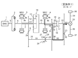
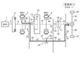
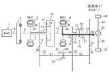
- FIG. 1 is a skeleton diagram schematically showing the configuration of a hybrid drive apparatus according to Embodiment 1 of the present invention.
- the hybrid drive device divides the rotational power of the engine 1 by the planetary gear mechanism 10 and transmits it to the axle and the first motor generator 3 or the second motor generator 4, as well as the first motor generator 3 and the second motor generator 4.
- One of the motor generators is used for regeneration, and the other motor generator is used to drive the wheels 36 and 37.
- the hybrid drive device includes an engine 1, a torque transmission device 2, a first motor generator 3 (MG1), a second motor generator 4 (MG2), a crankshaft 5, a shaft 6, a shaft 7, and a drive gear. 8
- the planetary gear mechanism 10 the shaft 15, the synchronization device 16, the drive gear 20, the shaft 22 (S3), the driven gear 23, the driven gear 24, the shaft 25 (S1), and the synchronization device 26.
- the engine 1 is an internal combustion engine that explodes and burns fuel in a cylinder and outputs rotational power by its thermal energy, an injector actuator (not shown) that adjusts the amount of fuel ejection, and an igniter that adjusts the ignition timing of the fuel It has an actuator etc.
- the rotational power of the engine 1 is transmitted to the torque transmission device 2 via the crankshaft 5.
- the engine 1 is communicably connected to the engine control device 40 and is controlled by the engine control device 40.
- the torque transmission device 2 is a device that transmits the rotational power of the crankshaft 5 to the shaft 6 in an intermittent manner.
- a torque converter, a clutch, a fluid coupling, etc. can be used for the torque transmission device 2.
- the rotational power of the torque transmission device 2 is transmitted to the carrier 14 of the planetary gear mechanism 10 via the shaft 6.
- the first motor generator 3 (MG1) is a synchronous generator motor that can be driven as a generator and also as a motor.
- the first motor generator 3 includes a stator 3b fixed to a transmission housing (not shown) and a rotor 3a that rotates on the inner periphery of the stator 3b.
- a coil is wound around the stator 3 b, and the coil is electrically connected to the power storage device 46 via the inverter 44.
- the rotor 3 a is coupled to the shaft 7 and rotates integrally with the sun gear 11 and the drive gear 8 of the planetary gear mechanism 10 via the shaft 7.
- the first motor generator 3 is controlled by a motor generator control device 41 via an inverter 44.
- the second motor generator 4 (MG2) is a synchronous generator motor that can be driven as a generator as well as a generator.
- the second motor generator 4 has a stator 4b fixed to a transmission housing (not shown) and a rotor 4a that rotates on the inner periphery of the stator 4b.
- a coil is wound around the stator 4 b, and the coil is electrically connected to the power storage device 46 via the inverter 45.
- the rotor 4 a is connected to the shaft 15 and rotates integrally with the ring gear 13 of the planetary gear mechanism 10 and the drive gear 17 of the synchronization device 16 via the shaft 15.
- Second motor generator 4 is controlled by motor generator control device 41 via inverter 45.
- the shaft 7 is a rotating shaft that rotates integrally with the rotor 3 a of the first motor generator 3, the sun gear 11 of the planetary gear mechanism 10, and the drive gear 8.
- the rotation speed of the shaft 7 corresponds to the rotation speed of the first motor generator 3 (MG1).
- the drive gear 8 meshes with the driven gear 24 with a predetermined gear ratio (for example, 1: 1). If the gear ratio between the drive gear 8 and the driven gear 24 is 1: 1, when the shaft 7 rotates once in the forward direction, the shaft 25 (S1) rotates once in the opposite direction.
- the planetary gear mechanism 10 is a power split mechanism that splits the rotational power of the engine 1 and transmits it to the first motor generator 3 or the second motor generator 4.
- the planetary gear mechanism 10 includes a sun gear 11, a pinion gear 12, a ring gear 13, and a carrier 14.
- the sun gear 11 meshes with the pinion gear 12 and rotates integrally with the rotor 3 a of the first motor generator 3 and the drive gear 8 via the shaft 7.
- the pinion gear 12 meshes with the sun gear 11 and the ring gear 13 and is rotatably supported by the carrier 14.
- Ring gear 13 meshes with pinion gear 12 and rotates integrally with rotor 4 a of second motor generator 4 and drive gear 17 of synchronization device 16 via shaft 15.
- the carrier 14 rotatably supports the pinion gear 12, and rotates when the pinion gear 12 revolves around the outer periphery of the sun gear 11.
- the rotational power of the engine 1 is transmitted to the carrier 14 via the crankshaft 5, the torque transmission device 2, and the shaft 6.
- the rotation ratio of the sun gear 11 and the ring gear 13 when the carrier 14 is fixed is set to 1: ⁇ (0 ⁇ ⁇ 1).
- the shaft 15 is a rotating shaft that rotates integrally with the ring gear 13 of the planetary gear mechanism 10, the rotor 4 a of the second motor generator 4, and the drive gear 17 of the synchronization device 16.
- the rotational speed of the shaft 15 corresponds to the rotational speed of the second motor generator 4 (MG2).
- the synchronization device 16 is a device that can selectively transmit the rotational power of the shaft 15 to the drive gear 20 or the shaft 22 by synchronizing the rotational speeds of the shaft 15 and the drive gear 20 or the shaft 22.
- the synchronization device 16 includes a drive gear 17, a sleeve 18, a driven gear 19, and a driven gear 21.
- the drive gear 17 rotates integrally with the ring gear 13 of the planetary gear mechanism 10 and the rotor 4 a of the second motor generator 4 via the shaft 15.
- the sleeve 18 is a cylindrical member that selectively connects the drive gear 17 and the driven gear 19 or the driven gear 21, and slides in the axial direction in response to the operation of the actuator 47.
- the sleeve 18 has a gear formed on the inner peripheral surface, and in the neutral state, meshes with only the drive gear 17, slides toward the driven gear 19, meshes with the drive gear 17 and the driven gear 19, and slides toward the driven gear 21.
- the driven gear 19 rotates integrally with the drive gear 20.
- the driven gear 21 rotates integrally with the driven gear 23 via the shaft 22.
- the drive gear 20 is a gear to which the rotational power of the shaft 15 is transmitted when the drive gear 17 and the driven gear 19 are connected via the sleeve 18 in the synchronization device 16.
- the drive gear 20 meshes with the driven gear 31 with a predetermined gear ratio (for example, 1: 3). If the gear ratio between the drive gear 20 and the driven gear 31 is 1: 3, when the drive gear 20 rotates three times in the forward direction, the shaft 30 (S2) rotates once in the reverse direction.
- the shaft 22 (S3) is a rotating shaft that rotates integrally with the driven gear 21 and the driven gear 23 of the synchronization device 16.
- the rotational power of the shaft 22 is differentially transmitted to the wheels 36 and 37 through the differential device 33 and the shafts 34 and 35.
- the driving gear 17 and the driven gear 21 are connected to each other through the sleeve 18 in the synchronization device 16, the rotational power of the shaft 15 is transmitted to the shaft 22.
- the driven gear 23 meshes with the drive gear 32 with a predetermined gear ratio (for example, 2: 1). If the gear ratio between the driven gear 23 and the drive gear 32 is 2: 1, when the shaft 30 (S2) rotates twice in the forward direction, the shaft 22 (S3) rotates once in the reverse direction.
- the shaft 25 (S 1) is a rotating shaft that rotates integrally with the driven gear 24 and the drive gear 27 of the synchronization device 26.
- the driven gear 24 meshes with the drive gear 8 with a predetermined gear ratio (for example, 1: 1).
- the synchronization device 26 is a device that can intermittently transmit the rotational power of the shaft 15 to the shaft 30 (S2) by synchronizing the rotational speeds of the shaft 25 (S1) and the shaft 30 (S2).
- the synchronization device 26 includes a drive gear 27, a sleeve 28, and a driven gear 29.
- the drive gear 27 rotates integrally with the driven gear 24 via the shaft 25.
- the sleeve 28 is a cylindrical member that intermittently connects the drive gear 27 and the driven gear 29, and slides in the axial direction in response to the operation of the actuator 48.
- the sleeve 28 has a gear formed on the inner peripheral surface, and meshes with only the drive gear 27 in the neutral state, and meshes with the drive gear 27 and the driven gear 29 by sliding toward the driven gear 29 side.
- the driven gear 29 rotates integrally with the driven gear 31 and the drive gear 32 via the shaft 30 (S2).
- the synchronization device 26 is used as an intermittent power transmission means between the shaft 25 (S1) and the shaft 30 (S2), but a clutch device may be used instead of the synchronization device 26. .
- the shaft 30 (S2) is a rotating shaft that rotates integrally with the driven gear 29, the driven gear 31, and the drive gear 32 of the synchronization device 26.
- the driven gear 31 meshes with the drive gear 20 with a predetermined gear ratio (for example, 3: 1).
- the drive gear 32 meshes with the driven gear 23 with a predetermined gear ratio (for example, 1: 2).
- the engine control device 40 is a computer (electronic control device) that controls the operation of the engine 1.
- the engine control device 40 includes various actuators (not shown; for example, an injector actuator, an igniter actuator, etc.) and various sensors (not shown; for example, an accelerator opening sensor, a shift position sensor, a rotation sensor, etc.) built in the engine 1. )
- the hybrid control device 43 are communicably connected.
- the engine control device 40 performs control processing based on a predetermined program (including a database, a map, and the like) in accordance with a control signal from the hybrid control device 43.
- the motor generator control device 41 is a computer (electronic control device) that controls the operation of the motor generators 3 and 4 via inverters 44 and 45.
- the motor generator control device 41 is communicably connected to the inverters 44 and 45, various sensors (not shown; for example, a rotation sensor) and the hybrid control device 43.
- the motor generator control device 41 performs control processing based on a predetermined program (including a database, a map, etc.) in response to a control signal from the hybrid control device 43.
- the transmission control device 42 is a computer (electronic control device) that controls the operation of the synchronization devices 16 and 26 via actuators 47 and 48.
- the transmission control device 42 is communicably connected to the actuators 47 and 48, various sensors (not shown; for example, a rotation sensor) and the hybrid control device 43.
- the transmission control device 42 performs control processing based on a predetermined program (including a database, a map, etc.) in response to a control signal from the hybrid control device 43.
- the hybrid control device 43 is a computer (electronic control device) that controls operations of the engine control device 40, the motor generator control device 41, and the transmission control device 42.
- the hybrid control device 43 is communicably connected to various sensors (not shown; for example, a rotation sensor), an engine control device 40, a motor generator control device 41, and a transmission control device 42.
- the hybrid control device 43 sends an engine control device 40, a motor generator control device 41, and a transmission control device 42 to the engine control device 40, the motor generator control device 41, and the transmission control device 42 based on a predetermined program (including a database, a map, etc.) according to a predetermined situation of the hybrid drive device. In response, a control signal is output.
- a predetermined program including a database, a map, etc.
- the inverters 44 and 45 control the operation (drive operation and regenerative operation) of the motor generators 3 and 4 in accordance with a control signal from the motor generator control device 41.
- the power storage device 46 is a device that stores electric power, and for example, a secondary battery or a capacitor that can be charged and discharged can be used. Power storage device 46 is electrically connected to motor generators 3 and 4 via inverters 44 and 45.
- Actuator 47 is a device that slides sleeve 18 of synchronizer 16 via a fork member (not shown) in response to a control signal from transmission control device 42.
- the actuator 48 is a device that slides the sleeve 28 of the synchronization device 26 via a fork member (not shown) in response to a control signal from the transmission control device 42.
- FIG. 2 is a schematic diagram illustrating a power transmission path in a first mode (low speed mode) in the hybrid drive device according to the first embodiment of the present invention.
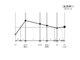
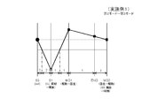
- FIG. 3 is a collinear diagram regarding the number of rotations showing the operation state of the first mode (low speed mode) in the hybrid drive apparatus according to Embodiment 1 of the present invention.
- FIG. 4 is a schematic diagram illustrating a power transmission path in a second mode (medium speed mode) in the hybrid drive device according to the first embodiment of the present invention.
- FIG. 5 is a collinear diagram with respect to the number of rotations showing an operation state when changing from the first mode to the second mode in the hybrid drive apparatus according to Embodiment 1 of the present invention.
- FIG. 6 is a schematic diagram illustrating a third mode (high-speed mode) power transmission path in the hybrid drive apparatus according to the first embodiment of the present invention.
- FIG. 7 is a collinear diagram with respect to the number of revolutions showing an operation state when changing from the second mode to the third mode in the hybrid drive apparatus according to Embodiment 1 of the present invention.
- a first mode in which the rotational power of the second motor generator 4 (MG2) is transmitted to the shaft 22 (S3) via the shaft 30 (S2)
- a second mode in which the rotational power of one motor generator 3 (MG1) is transmitted to the shaft 22 (S3) via the shaft 25 (S1) and the shaft 30 (S2) (see FIG. 4), and the second motor generator 4
- There is a third mode in which the rotational power of MG2) is directly transmitted to the shaft 22 (S3).
- the rotational power of the second motor generator 4 is transmitted to the drive gear 20 via the shaft 15 and the synchronization device 16, and is decelerated between the drive gear 20 and the driven gear 31 (here, the reduction ratio 1 / 3) and transmitted to the shaft 30 (S2), decelerated between the drive gear 32 and the driven gear 23 (here, a reduction ratio of 1/2) and transmitted to the shaft 22 (S3), the differential device 33 and the shaft It is transmitted to wheels 36 and 37 via 34 and 35.
- the rotational speed of shaft 22 (S3) is 1/6 of the rotational speed of second motor generator 4 (MG2).
- the first motor generator 3 (MG1) drives, the second motor generator 4 (MG2) regenerates, and the synchronizing device 16 has the shaft 15, the drive gear 20, and the shaft 22 (S3). And the shaft 25 (S1) and the shaft 30 (S2) are connected in the synchronization device 26. Therefore, the rotational power of the first motor generator 3 (MG1) is transmitted from the shaft 7 to the shaft 25 (S1) without being decelerated between the drive gear 8 and the driven gear 24 (here, the reduction ratio 1/1).
- the motor 15 is regenerated by the first motor generator 3 (MG1) and driven by the second motor generator 4 (MG2), and the shaft 15 and the shaft 22 (S3) are connected in the synchronization device 16.
- the shaft 25 (S1) and the shaft 30 (S2) are opened. Therefore, the rotational power of the second motor generator 4 (MG2) is transmitted to the shaft 22 (S3) via the shaft 7 and the synchronizer 16 without being decelerated, and the wheels 36 via the differential device 33 and the shafts 34 and 35. , 37.
- the rotation speed of the shaft 22 (S3) is the same as the rotation speed of the second motor generator 4 (MG2).
- the first mode (see Fig. 2; reduction ratio 1/6) that can take a large reduction ratio among the three output modes is selected and used to increase the speed.
- the third mode (see FIG. 6; reduction ratio 1/1), which is the minimum reduction ratio, is selected and used from the three output modes.
- the second mode (see FIG. 4; reduction ratio 1/2) having an intermediate reduction ratio is selected and used.
- each mode a continuously variable transmission operation is performed, but in the first mode (see FIG. 2), at the initial stage of the start, the rotation speed of the first motor generator 3 (MG1) is the first while the engine 1 is being accelerated. 2
- the motor generator 4 (MG2) is likely to increase in number of rotations (see FIG. 3), so that the vehicle is efficiently regenerated by the first motor generator 3 (MG1) and driven by the second motor generator 4 (MG2). Can be accelerated.
- the rotational speed of the second motor generator 4 (MG2) exceeds the rotational speed of the first motor generator 3 (MG1), and the rotational speed of the shaft 25 (S1) The point at which the rotational speed of the shaft 30 (S2) matches is reached (see FIG. 5).
- the first motor generator 3 (MG1) is switched from regeneration to driving
- the second motor generator 4 (MG2) is switched from driving.
- Switching to regeneration switching from the state in which the shaft 15 and the drive gear 20 are connected in the synchronization device 16 to the state in which the shaft 15, the drive gear 20 and the shaft 22 (S3) are opened, and in the synchronization device 26, the shaft 25 (S1 ) And the shaft 30 (S2) are switched from the opened state to the connected state.
- Such switching is performed under the control of the electronic control unit (40 to 43 in FIG. 1), and the first mode (see FIG. 2) is monitored by monitoring the rotational speeds of the engine 1 and the shaft 22 (S3).
- a switching point to two modes (see FIG. 4) can be detected.
- the first motor generator 3 (MG1) is in a state where the engine 1 is accelerated. Is lower than the rotational speed of the second motor generator 4 (MG2) (see FIG. 5), and is driven by the first motor generator 3 (MG1) and regenerated by the second motor generator 4 (MG2).
- the vehicle can be accelerated efficiently.
- the rotational speed of the first motor generator 3 (MG1) exceeds the rotational speed of the second motor generator 4 (MG2), and the second motor generator 4 (MG2) The point at which the rotational speed matches the rotational speed of the shaft 30 (S2) is reached (see FIG. 7).
- the first motor generator 3 (MG1) is switched from driving to regeneration, and the second motor generator 4 (MG2) is switched from regeneration.
- Switching to driving the shaft 15 and the driving gear 20 and the shaft 22 (S3) in the synchronization device 16 are switched from the opened state to the state in which the shaft 15 and the shaft 22 (S3) are connected, and the shaft 25 (S1) is switched in the synchronization device 26.
- And the shaft 30 (S2) are switched from the connected state to the opened state.
- Such switching is performed by the control of the electronic control unit (40 to 43 in FIG. 1), and the second mode (see FIG. 4) is monitored by monitoring the rotational speeds of the engine 1 and the shaft 22 (S3).
- a switching point to the 3 mode can be detected.
- the second motor generator 4 (MG2) is in a state where the engine 1 is accelerated. Is lower than the rotational speed of the first motor generator 3 (MG1) (see FIG. 7), and is regenerated by the first motor generator 3 (MG1) and driven by the second motor generator 4 (MG2). The vehicle can be accelerated efficiently.
- the first motor generator 3 does not enter a so-called power circulation state in which the reverse rotational power running state / the second motor generator 4 (MG2) operates in the forced regeneration state, and the reduction ratio is increased. Since it is possible to take a wide range, the internal combustion engine can be operated under optimum fuel consumption conditions, so that power transmission efficiency and fuel consumption can be improved. Further, since there is only one row of planetary gear mechanisms in the hybrid drive device, the overall length of the transmission can be shortened, and the mountability to the vehicle can be improved. Furthermore, in the process of accelerating the vehicle, the mode can be switched smoothly without lowering the rotational speed of the engine 1, so that no shift time is required and no shift shock occurs even when the engine 1 is driven to accelerate. can do.
Abstract
Description
本発明は、日本国特許出願:特願2010-045443号(2010年3月2日出願)の優先権主張に基づくものであり、同出願の全記載内容は引用をもって本書に組み込み記載されているものとする。 [Description of related applications]
The present invention is based on the priority claim of Japanese patent application: Japanese Patent Application No. 2010-054443 (filed on March 2, 2010), the entire contents of which are incorporated herein by reference. Shall.
2 トルク伝動装置
3 第1モータジェネレータ(MG1)
3a ロータ
3b ステータ
4 第2モータジェネレータ(MG2)
4a ロータ
4b ステータ
5 クランクシャフト
6、7 シャフト
8 駆動ギヤ
10 遊星歯車機構(歯車機構)
11 サンギヤ
12 ピニオンギヤ
13 リングギヤ
14 キャリヤ
15 シャフト
16 同期装置(第1動力伝達切替機構)
17 駆動ギヤ
18 スリーブ
19 従動ギヤ
20 駆動ギヤ(回転要素)
21 従動ギヤ
22 シャフト(S3、第3シャフト)
23 従動ギヤ
24 従動ギヤ
25 シャフト(S1、第1シャフト)
26 同期装置(第2動力伝達切替機構)
27 駆動ギヤ
28 スリーブ
29 従動ギヤ
30 シャフト(S2、第2シャフト)
31 従動ギヤ
32 駆動ギヤ
33 ディファレンシャル装置
34、35 シャフト
36、37 車輪
40 エンジン制御装置(電子制御装置)
41 モータジェネレータ制御装置(電子制御装置)
42 変速機制御装置(電子制御装置)
43 ハイブリッド制御装置(電子制御装置)
44、45 インバータ
46 蓄電装置
47、48 アクチュエータ 1 Engine (ENG, internal combustion engine)
2
11
17
21 driven
23 driven
26 Synchronizer (second power transmission switching mechanism)
27
31
41 Motor generator control device (electronic control device)
42 Transmission control device (electronic control device)
43 Hybrid controller (electronic controller)
44, 45
Claims (9)
- 内燃機関の回転動力を、第1モータジェネレータ及び第2モータジェネレータに分配して伝達する歯車機構と、
前記第1モータジェネレータの回転動力が伝達される第1シャフトと、
回転要素と、
前記回転要素の回転動力が伝達される第2シャフトと、
前記第2シャフトの回転動力が伝達されるとともに、車輪を駆動する第3シャフトと、
前記第2モータジェネレータの回転動力の前記回転要素への伝達を許容する状態と、前記第3シャフトへの伝達を許容する状態と、前記回転要素及び前記第3シャフトへの伝達を禁止する状態との間を切り替え可能な第1動力伝達切替機構と、
前記第1シャフトの回転動力の前記第2シャフトへの伝達を許容する状態と、前記第2シャフトへの伝達を禁止する状態との間を切り替え可能な第2動力伝達切替機構と、
を備えるハイブリッド駆動装置。 A gear mechanism that distributes and transmits the rotational power of the internal combustion engine to the first motor generator and the second motor generator;
A first shaft to which the rotational power of the first motor generator is transmitted;
A rotating element;
A second shaft to which the rotational power of the rotating element is transmitted;
A third shaft for transmitting rotational power of the second shaft and driving a wheel;
A state allowing transmission of rotational power of the second motor generator to the rotating element, a state allowing transmission to the third shaft, and a state prohibiting transmission to the rotating element and the third shaft. A first power transmission switching mechanism capable of switching between,
A second power transmission switching mechanism capable of switching between a state in which transmission of rotational power of the first shaft to the second shaft is allowed and a state in which transmission to the second shaft is prohibited;
A hybrid drive device comprising: - 前記歯車機構は、
前記内燃機関の回転動力が入力されるサンギヤと、
前記サンギヤと噛み合うピニオンギヤと、
前記ピニオンギヤと噛み合うとともに、回転動力を前記第2モータジェネレータに向けて出力するリングギヤと、
前記ピニオンギヤを回転可能に支持するとともに、回転動力を前記第1モータジェネレータに向けて出力するキャリヤと、
を備える請求項1記載のハイブリッド駆動装置。 The gear mechanism is
A sun gear to which the rotational power of the internal combustion engine is input;
A pinion gear meshing with the sun gear;
A ring gear that meshes with the pinion gear and outputs rotational power to the second motor generator;
A carrier that rotatably supports the pinion gear and outputs rotational power to the first motor generator;
The hybrid drive device according to claim 1, comprising: - 前記内燃機関、前記第1モータジェネレータ、前記第2モータジェネレータ、前記第1動力伝達切替機構、及び前記第2動力伝達切替機構の動作を制御する電子制御装置を備える請求項1又は2記載のハイブリッド駆動装置。 The hybrid according to claim 1, further comprising: an electronic control unit that controls operations of the internal combustion engine, the first motor generator, the second motor generator, the first power transmission switching mechanism, and the second power transmission switching mechanism. Drive device.
- 前記電子制御装置は、
第1モードにおいて、前記第1モータジェネレータの回生を許容するように前記第1モータジェネレータを制御し、前記第2モータジェネレータの駆動を許容するように前記第2モータジェネレータを制御し、前記第1シャフトの回転動力の前記第2シャフトへの伝達を禁止するように前記第1動力伝達切替機構を制御し、前記第2モータジェネレータの回転動力の前記回転要素への伝達を許容するように前記第2動力伝達切替機構を制御し、
前記第1モードよりも車速が速いときに用いる第2モードにおいて、前記第1モータジェネレータの駆動を許容するように前記第1モータジェネレータを制御し、前記第2モータジェネレータの回生を許容するように前記第2モータジェネレータを制御し、前記第1シャフトの回転動力の前記第2シャフトへの伝達を許容するように前記第1動力伝達切替機構を制御し、前記第2モータジェネレータの回転動力の前記回転要素及び前記第3シャフトへの伝達を禁止するように前記第2動力伝達切替機構を制御し、
前記第2モードよりも車速が速いときに用いる第3モードにおいて、前記第1モータジェネレータの回生を許容するように前記第1モータジェネレータを制御し、前記第2モータジェネレータの駆動を許容するように前記第2モータジェネレータを制御し、前記第1シャフトの回転動力の前記第2シャフトへの伝達を禁止するように前記第1動力伝達切替機構を制御し、前記第2モータジェネレータの回転動力の前記第3シャフトへの伝達を許容するように前記第2動力伝達切替機構を制御する請求項3記載のハイブリッド駆動装置。 The electronic control device
In the first mode, the first motor generator is controlled to allow regeneration of the first motor generator, the second motor generator is controlled to allow driving of the second motor generator, and the first motor generator is controlled. The first power transmission switching mechanism is controlled to prohibit transmission of rotational power of the shaft to the second shaft, and transmission of the rotational power of the second motor generator to the rotational element is allowed. 2 Control the power transmission switching mechanism,
In the second mode used when the vehicle speed is faster than the first mode, the first motor generator is controlled so as to allow the driving of the first motor generator, and the regeneration of the second motor generator is allowed. Controlling the second motor generator, controlling the first power transmission switching mechanism to allow transmission of the rotational power of the first shaft to the second shaft, and controlling the rotational power of the second motor generator Controlling the second power transmission switching mechanism to prohibit transmission to the rotating element and the third shaft;
In the third mode used when the vehicle speed is faster than the second mode, the first motor generator is controlled so as to allow regeneration of the first motor generator, and the driving of the second motor generator is allowed. The second motor generator is controlled, the first power transmission switching mechanism is controlled so as to prohibit transmission of the rotational power of the first shaft to the second shaft, and the rotational power of the second motor generator is controlled. The hybrid drive device according to claim 3, wherein the second power transmission switching mechanism is controlled to allow transmission to the third shaft. - 前記電子制御装置は、前記内燃機関の回転数と、前記第3シャフトの回転数とに基づいて、前記第1モード、前記第2モード、及び前記第3モードの間におけるモード切り替えを行う請求項4記載のハイブリッド駆動装置。 The electronic control unit performs mode switching among the first mode, the second mode, and the third mode based on the rotational speed of the internal combustion engine and the rotational speed of the third shaft. 4. The hybrid drive device according to 4.
- 前記電子制御装置は、前記内燃機関の回転数と、前記第3シャフトの回転数とに基づいて、
加速時において前記第1シャフトの回転数と前記第2シャフトの回転数とが一致すると判断したときに、前記第1モードから前記第2モードへのモード切り替えを行い、
加速時において前記第2モータジェネレータの回転数と前記第3シャフトの回転数とが一致すると判断したときに、前記第2モードから前記第3モードへのモード切り替えを行う請求項5記載のハイブリッド駆動装置。 The electronic control unit is based on the rotational speed of the internal combustion engine and the rotational speed of the third shaft.
When it is determined that the rotation speed of the first shaft and the rotation speed of the second shaft coincide with each other during acceleration, mode switching from the first mode to the second mode is performed.
6. The hybrid drive according to claim 5, wherein mode switching from the second mode to the third mode is performed when it is determined that the rotational speed of the second motor generator coincides with the rotational speed of the third shaft during acceleration. apparatus. - 前記ハイブリッド駆動装置は、車両に用いられ、
前記車両は、第1の速度と、前記第1の速度よりも速い第2の速度と、前記第2の速度よりも速い第3の速度により走行し、
前記電子制御装置は、前記車両が前記第1の速度で走行するときに用いられる第1モードを有し、前記第1モードにおいて、前記第1モータジェネレータの回生を許容するように前記第1モータジェネレータを制御し、前記第2モータジェネレータの駆動を許容するように前記第2モータジェネレータを制御し、前記第1シャフトの回転動力の前記第2シャフトへの伝達を禁止するように前記第1動力伝達切替機構を制御し、前記第2モータジェネレータの回転動力の前記回転要素への伝達を許容するように前記第2動力伝達機構を制御する請求項3記載のハイブリッド駆動装置。 The hybrid drive device is used in a vehicle,
The vehicle travels at a first speed, a second speed that is faster than the first speed, and a third speed that is faster than the second speed,
The electronic control unit has a first mode used when the vehicle travels at the first speed, and the first motor is configured to allow regeneration of the first motor generator in the first mode. Controlling the generator, controlling the second motor generator to permit driving of the second motor generator, and prohibiting transmission of rotational power of the first shaft to the second shaft. 4. The hybrid drive device according to claim 3, wherein a transmission switching mechanism is controlled to control the second power transmission mechanism so as to allow transmission of rotational power of the second motor generator to the rotating element. 5. - 前記ハイブリッド駆動装置は、車両に用いられ、
前記車両は、第1の速度と、前記第1の速度よりも速い第2の速度と、前記第2の速度よりも速い第3の速度により走行し、
前記電子制御装置は、前記車両が前記第2の速度で走行するときに用いられる第2モードを有し、前記第2モードにおいて、前記第1モータジェネレータの駆動を許容するように前記第1モータジェネレータを制御し、前記第2モータジェネレータの回生を許容するように前記第2モータジェネレータを制御し、前記第1シャフトの回転動力の前記第2シャフトへの伝達を許容するように前記第1動力伝達切替機構を制御し、前記第2モータジェネレータの回転動力の前記回転要素及び前記第3シャフトへの伝達を禁止するように前記第2動力伝達機構を制御する請求項3記載のハイブリッド駆動装置。 The hybrid drive device is used in a vehicle,
The vehicle travels at a first speed, a second speed that is faster than the first speed, and a third speed that is faster than the second speed,
The electronic control unit has a second mode used when the vehicle travels at the second speed, and the first motor is allowed to permit driving of the first motor generator in the second mode. Controlling the generator, controlling the second motor generator so as to allow regeneration of the second motor generator, and allowing the first power to transmit the rotational power of the first shaft to the second shaft. The hybrid drive device according to claim 3, wherein a transmission switching mechanism is controlled to control the second power transmission mechanism so as to prohibit transmission of rotational power of the second motor generator to the rotating element and the third shaft. - 前記ハイブリッド駆動装置は、車両に用いられ、
前記車両は、第1の速度と、前記第1の速度よりも速い第2の速度と、前記第2の速度よりも速い第3の速度により走行し、
前記電子制御装置は、前記車両が前記第3の速度で走行するときに用いられる第3モードを有し、前記第3モードにおいて、前記第1モータジェネレータの回生を許容するように前記第1モータジェネレータを制御し、前記第2モータジェネレータの駆動を許容するように前記第2モータジェネレータを制御し、前記第1シャフトの回転動力の前記第2シャフトへの伝達を禁止するように前記第1動力伝達切替機構を制御し、前記第2モータジェネレータの回転動力の前記第3シャフトへの伝達を許容するように前記第2動力伝達機構を制御する請求項3記載のハイブリッド駆動装置。 The hybrid drive device is used in a vehicle,
The vehicle travels at a first speed, a second speed that is faster than the first speed, and a third speed that is faster than the second speed,
The electronic control unit has a third mode used when the vehicle travels at the third speed, and the first motor is configured to allow regeneration of the first motor generator in the third mode. Controlling the generator, controlling the second motor generator to permit driving of the second motor generator, and prohibiting transmission of rotational power of the first shaft to the second shaft. The hybrid drive device according to claim 3, wherein a transmission switching mechanism is controlled to control the second power transmission mechanism so as to allow transmission of rotational power of the second motor generator to the third shaft.
Priority Applications (3)
| Application Number | Priority Date | Filing Date | Title |
|---|---|---|---|
| CN201180012190.3A CN102781698B (en) | 2010-03-02 | 2011-02-23 | Hybrid drive device |
| DE112011100753T DE112011100753T5 (en) | 2010-03-02 | 2011-02-23 | Hybridanrtiebsvorrichtung |
| US13/576,236 US9046156B2 (en) | 2010-03-02 | 2011-02-23 | Hybrid drive device |
Applications Claiming Priority (2)
| Application Number | Priority Date | Filing Date | Title |
|---|---|---|---|
| JP2010045443A JP5273069B2 (en) | 2010-03-02 | 2010-03-02 | Hybrid drive device |
| JP2010-045443 | 2010-03-02 |
Publications (1)
| Publication Number | Publication Date |
|---|---|
| WO2011108408A1 true WO2011108408A1 (en) | 2011-09-09 |
Family
ID=44542062
Family Applications (1)
| Application Number | Title | Priority Date | Filing Date |
|---|---|---|---|
| PCT/JP2011/053903 WO2011108408A1 (en) | 2010-03-02 | 2011-02-23 | Hybrid drive device |
Country Status (5)
| Country | Link |
|---|---|
| US (1) | US9046156B2 (en) |
| JP (1) | JP5273069B2 (en) |
| CN (1) | CN102781698B (en) |
| DE (1) | DE112011100753T5 (en) |
| WO (1) | WO2011108408A1 (en) |
Cited By (2)
| Publication number | Priority date | Publication date | Assignee | Title |
|---|---|---|---|---|
| WO2012037013A1 (en) * | 2010-09-15 | 2012-03-22 | Chrysler Llc | Multi-mode drive unit |
| CN104203690A (en) * | 2012-03-21 | 2014-12-10 | 丰田自动车株式会社 | Drive control device for hybrid vehicle |
Families Citing this family (30)
| Publication number | Priority date | Publication date | Assignee | Title |
|---|---|---|---|---|
| DE102011087995A1 (en) * | 2011-12-08 | 2013-06-13 | Zf Friedrichshafen Ag | Transmission and drive train with a transmission |
| DE102013011566A1 (en) * | 2013-06-22 | 2014-12-24 | Daimler Ag | Transmission device for a motor vehicle |
| WO2014208568A1 (en) * | 2013-06-26 | 2014-12-31 | 日立建機株式会社 | Hybrid work machine |
| KR101550986B1 (en) * | 2013-11-25 | 2015-09-07 | 현대자동차주식회사 | Hybrid power train for vehicle |
| WO2015113415A1 (en) | 2014-01-30 | 2015-08-06 | Byd Company Limited | Power transmission system for vehicle and vehicle comprising the same |
| US9568080B2 (en) | 2014-01-30 | 2017-02-14 | Byd Company Limited | Power transmission system for vehicle and vehicle comprising the same |
| WO2015113414A1 (en) | 2014-01-30 | 2015-08-06 | Byd Company Limited | Power transmission system for vehicle and vehicle comprising the same |
| CN104276031B (en) | 2014-01-30 | 2016-01-13 | 比亚迪股份有限公司 | Vehicle and drived control method thereof |
| WO2015113416A1 (en) | 2014-01-30 | 2015-08-06 | Byd Company Limited | Power transmission system for vehicle and vehicle comprising the same |
| US10670123B2 (en) | 2014-01-30 | 2020-06-02 | Byd Company Limited | Power transmission system for vehicle and vehicle comprising the same |
| WO2015113425A1 (en) * | 2014-01-30 | 2015-08-06 | 比亚迪股份有限公司 | Vehicle and power transmission system thereof |
| CN104279311B (en) | 2014-01-30 | 2015-11-25 | 比亚迪股份有限公司 | The controlling method of synchronizer and vehicle in vehicle |
| EP3100886B1 (en) | 2014-01-30 | 2022-06-01 | BYD Company Limited | Vehicle and power transmission system thereof |
| US9464713B2 (en) | 2014-06-24 | 2016-10-11 | Deere & Company | Modular assembly for power train |
| EP2995489B1 (en) | 2014-09-10 | 2020-01-22 | BYD Company Limited | Transmission unit, power transmission system and vehicle comprising the same |
| US9874266B2 (en) | 2014-09-10 | 2018-01-23 | Byd Company Limited | Power transmission system and vehicle comprising the same |
| US9568066B2 (en) | 2014-09-10 | 2017-02-14 | Byd Company Limited | Power transmission system and vehicle comprising the same |
| US10166973B2 (en) | 2014-10-20 | 2019-01-01 | Byd Company Limited | Vehicle and shifting control method and power transmission system thereof |
| CN104608760B (en) | 2014-10-20 | 2016-05-25 | 比亚迪股份有限公司 | Hybrid vehicle and shift control method thereof, power drive system |
| KR101584012B1 (en) * | 2014-11-25 | 2016-01-11 | 현대자동차주식회사 | Powertrain for hybrid vehicle |
| KR101637743B1 (en) | 2014-11-25 | 2016-07-21 | 현대자동차주식회사 | Powertrain for hybrid vehicle |
| KR101584013B1 (en) | 2014-11-25 | 2016-01-20 | 현대자동차주식회사 | Powertrain for hybrid vehicle |
| US9889734B2 (en) | 2015-01-16 | 2018-02-13 | Byd Company Limited | Power transmission system and vehicle comprising the same |
| CN104773063B (en) | 2015-01-16 | 2015-12-02 | 比亚迪股份有限公司 | Change-speed box, Power Train are unified vehicle |
| WO2016112652A1 (en) | 2015-01-16 | 2016-07-21 | Byd Company Limited | Power transmission system and vehicle comprising the same |
| WO2016112653A1 (en) | 2015-01-16 | 2016-07-21 | Byd Company Limited | Transmission unit, power transmission system and vehicle comprising the same |
| EP3386789A1 (en) * | 2015-12-07 | 2018-10-17 | Dana Heavy Vehicle Systems Group, LLC | Distributed drivetrain architectures for commercial vehicles with a hybrid electric powertrain and dual range disconnect axles |
| JP6830053B2 (en) * | 2017-12-05 | 2021-02-17 | 株式会社豊田中央研究所 | Series hybrid car |
| DE102019202966A1 (en) * | 2019-03-05 | 2020-09-10 | Zf Friedrichshafen Ag | Hybrid drive train for a motor vehicle and a method for operating a hybrid drive train |
| CN114407639B (en) * | 2022-03-11 | 2022-08-19 | 深圳市悦成汽车技术有限公司 | Multi-mode gearbox assembly of hybrid electric vehicle |
Citations (5)
| Publication number | Priority date | Publication date | Assignee | Title |
|---|---|---|---|---|
| JP2005001564A (en) * | 2003-06-12 | 2005-01-06 | Honda Motor Co Ltd | Power transmission device for hybrid vehicle |
| JP2005138692A (en) * | 2003-11-06 | 2005-06-02 | Honda Motor Co Ltd | Power transmission device of hybrid vehicle |
| JP2006282069A (en) * | 2005-04-01 | 2006-10-19 | Toyota Motor Corp | Hybrid drive device |
| JP2007326422A (en) * | 2006-06-06 | 2007-12-20 | Toyota Motor Corp | Hybrid vehicle driving device |
| JP2009067091A (en) * | 2007-09-10 | 2009-04-02 | Toyota Motor Corp | Hybrid drive |
Family Cites Families (5)
| Publication number | Priority date | Publication date | Assignee | Title |
|---|---|---|---|---|
| US5931757A (en) | 1998-06-24 | 1999-08-03 | General Motors Corporation | Two-mode, compound-split electro-mechanical vehicular transmission |
| US6672415B1 (en) | 1999-05-26 | 2004-01-06 | Toyota Jidosha Kabushiki Kaisha | Moving object with fuel cells incorporated therein and method of controlling the same |
| JP3569210B2 (en) * | 2000-08-11 | 2004-09-22 | 本田技研工業株式会社 | Power transmission device for hybrid vehicle and control method therefor |
| US7108087B2 (en) * | 2003-06-12 | 2006-09-19 | Honda Motor Co., Ltd. | Power transmitting apparatus for hybrid vehicle |
| JP2010045443A (en) | 2008-08-08 | 2010-02-25 | Japan Radio Co Ltd | Carrier wave generation circuit |
-
2010
- 2010-03-02 JP JP2010045443A patent/JP5273069B2/en active Active
-
2011
- 2011-02-23 WO PCT/JP2011/053903 patent/WO2011108408A1/en active Application Filing
- 2011-02-23 US US13/576,236 patent/US9046156B2/en active Active
- 2011-02-23 CN CN201180012190.3A patent/CN102781698B/en active Active
- 2011-02-23 DE DE112011100753T patent/DE112011100753T5/en not_active Withdrawn
Patent Citations (5)
| Publication number | Priority date | Publication date | Assignee | Title |
|---|---|---|---|---|
| JP2005001564A (en) * | 2003-06-12 | 2005-01-06 | Honda Motor Co Ltd | Power transmission device for hybrid vehicle |
| JP2005138692A (en) * | 2003-11-06 | 2005-06-02 | Honda Motor Co Ltd | Power transmission device of hybrid vehicle |
| JP2006282069A (en) * | 2005-04-01 | 2006-10-19 | Toyota Motor Corp | Hybrid drive device |
| JP2007326422A (en) * | 2006-06-06 | 2007-12-20 | Toyota Motor Corp | Hybrid vehicle driving device |
| JP2009067091A (en) * | 2007-09-10 | 2009-04-02 | Toyota Motor Corp | Hybrid drive |
Cited By (3)
| Publication number | Priority date | Publication date | Assignee | Title |
|---|---|---|---|---|
| WO2012037013A1 (en) * | 2010-09-15 | 2012-03-22 | Chrysler Llc | Multi-mode drive unit |
| US8512187B2 (en) | 2010-09-15 | 2013-08-20 | Chrysler Group Llc | Multi-mode drive unit |
| CN104203690A (en) * | 2012-03-21 | 2014-12-10 | 丰田自动车株式会社 | Drive control device for hybrid vehicle |
Also Published As
| Publication number | Publication date |
|---|---|
| JP5273069B2 (en) | 2013-08-28 |
| DE112011100753T5 (en) | 2013-03-21 |
| US20120310461A1 (en) | 2012-12-06 |
| JP2011178307A (en) | 2011-09-15 |
| CN102781698A (en) | 2012-11-14 |
| US9046156B2 (en) | 2015-06-02 |
| CN102781698B (en) | 2015-07-22 |
Similar Documents
| Publication | Publication Date | Title |
|---|---|---|
| JP5273069B2 (en) | Hybrid drive device | |
| RU2585501C2 (en) | Actuator for hybrid vehicle | |
| JP4274268B2 (en) | Power transmission device | |
| JP4331228B2 (en) | Power transmission device for vehicle | |
| JP4140647B2 (en) | Power output device and hybrid vehicle | |
| US8177671B2 (en) | Control system for hybrid drive unit | |
| US20100048353A1 (en) | Starting control system for engines | |
| JP5874812B2 (en) | Drive control apparatus for hybrid vehicle | |
| JP2008105496A (en) | Power output device and hybrid automobile | |
| JP2008105531A (en) | Power output device and hybrid automobile | |
| JP2008308012A (en) | Power output device, and hybrid automobile equipped with the same | |
| EP2399795A2 (en) | Shift controller and shift controlling method for a hybrid vehicle | |
| JP2007326422A (en) | Hybrid vehicle driving device | |
| JP4329749B2 (en) | Control device for vehicle drive device | |
| JP4919080B2 (en) | Power output device | |
| JP2008256075A (en) | Power transmission device | |
| JP2006282070A (en) | Hybrid driving device | |
| JP2011110966A (en) | Hybrid vehicle | |
| JP2009166793A (en) | Hybrid driving device | |
| JP2008120139A (en) | Hybrid drive system | |
| JP2010269717A (en) | Drive device for vehicle | |
| JP2012056510A (en) | Drive device of hybrid vehicle | |
| JP2014019328A (en) | Control device for hybrid vehicle | |
| JP2008062679A (en) | Automotive drive device | |
| JP2013159212A (en) | Power transmission device |
Legal Events
| Date | Code | Title | Description |
|---|---|---|---|
| WWE | Wipo information: entry into national phase |
Ref document number: 201180012190.3 Country of ref document: CN |
|
| 121 | Ep: the epo has been informed by wipo that ep was designated in this application |
Ref document number: 11750518 Country of ref document: EP Kind code of ref document: A1 |
|
| WWE | Wipo information: entry into national phase |
Ref document number: 13576236 Country of ref document: US |
|
| WWE | Wipo information: entry into national phase |
Ref document number: 112011100753 Country of ref document: DE Ref document number: 1120111007531 Country of ref document: DE |
|
| 122 | Ep: pct application non-entry in european phase |
Ref document number: 11750518 Country of ref document: EP Kind code of ref document: A1 |