WO2011108291A1 - 表示装置 - Google Patents
表示装置 Download PDFInfo
- Publication number
- WO2011108291A1 WO2011108291A1 PCT/JP2011/050287 JP2011050287W WO2011108291A1 WO 2011108291 A1 WO2011108291 A1 WO 2011108291A1 JP 2011050287 W JP2011050287 W JP 2011050287W WO 2011108291 A1 WO2011108291 A1 WO 2011108291A1
- Authority
- WO
- WIPO (PCT)
- Prior art keywords
- input
- sensor
- state
- input button
- operator
- Prior art date
- Legal status (The legal status is an assumption and is not a legal conclusion. Google has not performed a legal analysis and makes no representation as to the accuracy of the status listed.)
- Ceased
Links
Images







Classifications
-
- G—PHYSICS
- G06—COMPUTING OR CALCULATING; COUNTING
- G06F—ELECTRIC DIGITAL DATA PROCESSING
- G06F3/00—Input arrangements for transferring data to be processed into a form capable of being handled by the computer; Output arrangements for transferring data from processing unit to output unit, e.g. interface arrangements
- G06F3/01—Input arrangements or combined input and output arrangements for interaction between user and computer
- G06F3/048—Interaction techniques based on graphical user interfaces [GUI]
- G06F3/0487—Interaction techniques based on graphical user interfaces [GUI] using specific features provided by the input device, e.g. functions controlled by the rotation of a mouse with dual sensing arrangements, or of the nature of the input device, e.g. tap gestures based on pressure sensed by a digitiser
- G06F3/0488—Interaction techniques based on graphical user interfaces [GUI] using specific features provided by the input device, e.g. functions controlled by the rotation of a mouse with dual sensing arrangements, or of the nature of the input device, e.g. tap gestures based on pressure sensed by a digitiser using a touch-screen or digitiser, e.g. input of commands through traced gestures
- G06F3/04886—Interaction techniques based on graphical user interfaces [GUI] using specific features provided by the input device, e.g. functions controlled by the rotation of a mouse with dual sensing arrangements, or of the nature of the input device, e.g. tap gestures based on pressure sensed by a digitiser using a touch-screen or digitiser, e.g. input of commands through traced gestures by partitioning the display area of the touch-screen or the surface of the digitising tablet into independently controllable areas, e.g. virtual keyboards or menus
-
- G—PHYSICS
- G06—COMPUTING OR CALCULATING; COUNTING
- G06F—ELECTRIC DIGITAL DATA PROCESSING
- G06F3/00—Input arrangements for transferring data to be processed into a form capable of being handled by the computer; Output arrangements for transferring data from processing unit to output unit, e.g. interface arrangements
- G06F3/01—Input arrangements or combined input and output arrangements for interaction between user and computer
- G06F3/03—Arrangements for converting the position or the displacement of a member into a coded form
- G06F3/041—Digitisers, e.g. for touch screens or touch pads, characterised by the transducing means
- G06F3/042—Digitisers, e.g. for touch screens or touch pads, characterised by the transducing means by opto-electronic means
-
- G—PHYSICS
- G06—COMPUTING OR CALCULATING; COUNTING
- G06F—ELECTRIC DIGITAL DATA PROCESSING
- G06F2203/00—Indexing scheme relating to G06F3/00 - G06F3/048
- G06F2203/041—Indexing scheme relating to G06F3/041 - G06F3/045
- G06F2203/04101—2.5D-digitiser, i.e. digitiser detecting the X/Y position of the input means, finger or stylus, also when it does not touch, but is proximate to the digitiser's interaction surface and also measures the distance of the input means within a short range in the Z direction, possibly with a separate measurement setup
-
- G—PHYSICS
- G06—COMPUTING OR CALCULATING; COUNTING
- G06F—ELECTRIC DIGITAL DATA PROCESSING
- G06F2203/00—Indexing scheme relating to G06F3/00 - G06F3/048
- G06F2203/048—Indexing scheme relating to G06F3/048
- G06F2203/04805—Virtual magnifying lens, i.e. window or frame movable on top of displayed information to enlarge it for better reading or selection
Definitions
- the present invention relates to a display device having a touch panel function.
- a display device in which a display unit and an input unit are integrated is widely used in order to reduce the size of the device.
- mobile terminals such as mobile phones, PDAs (Personal Digital Assistants), and notebook PCs (personal computers)
- touch panels that can be operated by touching the display screen with a finger or a touch pen are becoming mainstream. is there.
- Such a display device includes a touch panel as an input unit, and the operator touches various input buttons displayed on the display screen of the touch panel, thereby executing a function associated with the touched input button.
- the input button using software is called a soft key
- a mechanical input button provided in hardware separately from the display unit is called a hard key.
- the display unit is also relatively small. For this reason, the size of each input button displayed on the display screen is naturally reduced.
- the touch panel when the touch panel is operated with a finger, if the displayed input button is smaller than the finger, it is difficult to confirm the input button that is actually pressed. For this reason, the operator may be concerned about whether he or she has actually pressed the desired input button, or has not pressed another input button that is in proximity, and may not be able to operate smoothly.
- the input button of a push button type mobile phone using hard keys is generally provided with irregularities.
- the operator recognizes the unevenness of each input button with a light press that is not input, and pushes after confirming the desired input button.
- the touch panel type portable information terminal has no unevenness as in the case of using a hard key as an input button. For this reason, the input button cannot be recognized before the input button is pressed, and the user feels uncomfortable. In particular, for an operator unfamiliar with touch panel operation, there is a great sense of discomfort.
- Patent Document 1 discloses performing input by touching a touch panel with a finger twice. In Patent Document 1, it is determined that the input buttons around the touch coordinates are rearranged and displayed in an enlarged manner by the first touch, and the touch coordinate input buttons are pressed by the second touch.
- Patent Documents 2 to 4 disclose that an input button around a touch coordinate is enlarged by touching a touch panel, and input is performed by releasing a finger.
- the input button of the coordinate data touched immediately before is displayed based on the coordinate data touched immediately before and the display position of the input button enlarged on the display screen. It is determined that is pressed.
- Patent Document 5 a sensor for detecting the position of a finger or the like is provided in the display input unit, and processing performed when an input button on the display panel corresponding to the position of the finger or the like detected by the sensor is touched. It is disclosed that contents are provided by display or sound before an operator touches an input button.
- a display button is selected and information is provided in a non-contact state, and an operator touches the input button to execute processing using the input button.
- Patent Document 1 always requires two touches for input confirmation. In addition, after touching the touch panel once, it is necessary to wait for the enlarged display and touch again. For this reason, it becomes troublesome twice and operability is bad.
- Patent Document 5 an input is executed if the input button is touched even a little. For this reason, even if the tip of the touch panel touches the touch panel in an attempt to bring a finger, a touch pen, or the like closer, the input is executed.
- the present invention has been made in view of the above problems, and its purpose is to execute a function different from that when the input button is normally touched by bringing a finger or an object close to or slightly touching the display screen.
- An object of the present invention is to provide a highly convenient display device.
- the display device determines that the input state is a display panel that displays the input button on the display screen, and when the operator's finger or object is in contact with the input button over a certain area. , When the operator's finger or object is in contact with the input button less than the predetermined area, and the normal direction distance between the operator's finger or object and the input button is within a certain distance and non-contact A state determination unit that determines a certain time as a half-input state, and determines that the operator's finger or object is away from the input button in the normal direction to the non-input state, and the state determination unit And an information processing unit that executes a function associated with the state of the input button in accordance with the state of the input button determined in step (b).
- the input button is in a half-input state not only when the operator brings a finger or the like close to the input button but also when the operator touches the input button lightly.
- a function associated with the input button that is executed when it is determined that the input button is in the input state is referred to as an input function, and the execution is referred to as input processing.
- a function associated with the input button that is executed when it is determined that the input button is in the half-input state is referred to as a half-input function, and the execution thereof is referred to as a half-input process.
- execution of a function here means execution of the processing program for performing the function matched with the input button.
- Patent Documents 2 to 4 when an operator's finger touches the input button, the operator's finger touches the input button, or after the operator's finger touches the input button. Input processing is executed by releasing it. For this reason, in Patent Documents 2 to 4, the input process is always executed after the half-input process. However, according to the above configuration, only the half-input process can be executed even after the operator's finger or the like touches the input button. For this reason, convenience is high.
- a half input process can be executed before the input process of the input button is performed by bringing a finger or the like closer to the input button or lightly touching the input button. Therefore, it is not necessary to repeat the same operation in order to perform input processing as in Patent Document 1. For this reason, operativity can be improved.
- the half-input processing can be executed simply by bringing a finger or the like close to or touching the input button, the operator can input the half-input associated with the input button to the input button to be input. After confirming the execution result of the function, the input function can be executed by pressing the input button. For this reason, it is possible to perform an accurate input process, and it is possible to smoothly check the half-input process by the operator and the subsequent input process.
- a highly convenient display device that can execute a function different from that when the input button is normally touched by bringing a finger or object close to or slightly touching the display screen. Can be provided.
- the state determination unit determines that the operator's finger or object is in contact with the input button over a certain area as an input state, and the operator's finger or object is input.
- the button is in contact with less than the specified area, and when the normal direction distance between the operator's finger or object and the input button is within a certain distance and is not in contact, it is determined as a half-input state.
- the half-input function equivalent to half-pressing with a hard key It can be realized with the input button.
- the operation can be performed in the same manner as the half pressing of the hard keys. Further, only the half-input process can be executed even after the operator's finger touches the input button. For this reason, convenience is high.
- the half-input processing can be executed simply by bringing a finger or the like close to or touching the input button, the operator can input the half-input associated with the input button to the input button to be input. After confirming the execution result of the function, the input function can be executed by pressing the input button. For this reason, it is possible to perform an accurate input process, and it is possible to smoothly check the half-input process by the operator and the subsequent input process.
- FIG. 5 is a plan view illustrating a configuration of one pixel of the liquid crystal panel illustrated in FIG. 4. It is a top view which shows typically arrangement
- FIG. 1 It is sectional drawing which shows schematic structure of the principal part of a liquid crystal panel when a visible light sensor is used as an optical sensor. It is sectional drawing which shows schematic structure of the principal part of a liquid crystal panel when an infrared sensor is used as an optical sensor. It is another sectional view showing the schematic structure of the principal part of the liquid crystal panel when an infrared sensor is used as the optical sensor.
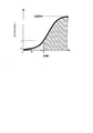
- (A)-(c) is a figure which shows the relationship between the distance between the display screen of a display part, and an operator's fingertip, and the shading of a shadow produced according to this distance. It is a graph which shows the relationship between the distance between the display screen of a display part, and an operator's fingertip, and the light reception amount of an optical sensor.
- FIG. 1 It is a flowchart which shows the flow of a process of touch operation by a state discrimination
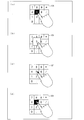
- (A)-(d) is a figure which shows an example of a half input process. It is another top view which shows typically arrangement
- a display device according to an embodiment will be described below with reference to FIGS.
- a mobile phone will be described as an example of the display device.
- FIGS. 3A and 3B are schematic configuration diagrams showing the appearance of the mobile phone according to the present embodiment.
- FIG. 3A is a non-input state of the input button
- FIG. 3B is a half-input state of the input button. Is shown.
- the non-input state indicates a normal state
- the half-input state indicates a state corresponding to half-pressing by a hard key.
- a numeric keypad is displayed as an input button 101 (function button, selection button) made up of soft keys.
- the display unit 11 displays an input result display unit 102 that performs display associated with the input button 101.
- the display screen 110 of the display unit 11 is formed to be full flat, for example.
- the display unit 11 is composed of a display panel such as a liquid crystal panel.
- the display panel is a touch panel integrated display panel having a touch panel function, and the display screen 110 is used as a touch panel (operation input unit). For this reason, the display unit 11 is used as a display unit / operation input unit.
- the mobile phone 100 has a half-input function corresponding to half-pressing with a hard key.
- the operator touches the input button 101 displayed on the display unit 11 with an object such as a finger or a touch pen in the mobile phone 100, the input of the input button 101 is executed, and the function associated with the input button 101 Is executed.
- functions other than input (half-input function) associated with the input button 101 are provided. Executed.
- FIG. 2 is a block diagram showing a schematic configuration of the mobile phone according to the present embodiment.
- the mobile phone 100 includes a control unit 1, a display unit 11, an audio output unit 12, an imaging unit 13, a sensor unit 14, a storage unit 15, an antenna unit 16, and a communication unit 17.
- a voice input unit (not shown) is provided.
- the control unit 1 comprehensively controls various components in the mobile phone 100.
- the function of the control unit 1 is realized by, for example, a CPU (Central Processing Unit) executing a program stored in the storage unit 15.
- a CPU Central Processing Unit
- the display unit 11 displays contents such as an image, text, and a moving image based on the display signal from the control unit 1. As described above, a display panel such as a liquid crystal panel is used for the display unit 11.
- a liquid crystal panel using liquid crystal as a display medium has an advantage that it is thin, lightweight, and consumes less power among various display panels. Therefore, it is particularly suitable for a display unit in a small portable terminal such as a cellular phone.
- the display mode of the liquid crystal panel is not particularly limited, and any display mode such as a TN (Twisted Nematic) mode, an IPS (In Plane Switching) mode, or a VA (VerticalmentAlignment) mode is applied. Can do.
- TN Transmission Nematic
- IPS In Plane Switching
- VA Very SelfAlignment
- a backlight (not shown) is provided on the back side of the liquid crystal panel as necessary.
- the audio output unit 12 converts the audio signal sent from the control unit 1 into a sound wave and outputs it to the outside.
- the audio output unit 12 includes, for example, a speaker, an earphone, an audio output connector, and the like.
- the imaging unit 13 performs imaging using a camera or the like based on a control signal from the control unit 1 and generates data such as an image and a moving image. In addition, the imaging unit 13 transmits the generated data to the control unit 1. Photo data and the like captured by the imaging unit 13 are stored in the storage unit 15, for example.
- an imaging element such as a CCD (Charge Coupled Device) or a CMOS (Complementary Metal-oxide Semiconductor) is used.
- CCD Charge Coupled Device
- CMOS Complementary Metal-oxide Semiconductor
- the sensor unit 14 is provided for providing the touch panel function in the liquid crystal panel.
- the sensor unit 14 is provided with a plurality of optical sensors corresponding to the respective pixels of the display unit 11.
- the storage unit 15 includes a memory for storing various data and programs.
- the storage unit 15 stores processing programs for executing functions associated with the input state and the half-input state of the input button 101, respectively.
- a display area when each input button 101 is displayed for each input button 101 is defined by XY coordinates on the display screen 110.
- the storage unit 15 includes a coordinate storage unit, an application information storage unit, and the like.
- the storage unit 15 may be a ROM (Read Only Memory), a RAM (Random Access Memory), or a flash ROM.
- the processing program may be rewritable via the communication unit 17, for example.
- the storage unit 15 also includes a rewritable nonvolatile memory such as a flash memory or an EEPROM that stores photographic data captured by the imaging unit 13.
- the antenna unit 16 sends out radio waves to the outside and receives radio waves from the outside.
- the communication unit 17 performs data communication with the outside via the antenna unit 16. Note that the communication may be wired communication or wireless communication.
- the communication unit 17 performs various processes such as baseband signal processing, data modulation / demodulation processing, and RF (Radio-Frequency) processing.
- control unit 1 [Schematic configuration of control unit 1] Next, a schematic configuration of the control unit 1 will be described below with reference to FIG.
- FIG. 1 is a block diagram showing a schematic configuration of a mobile phone 100 according to the present embodiment.
- control unit 1 includes a state determination unit 2, an information processing unit 3, and a function execution unit 4.
- the state determination unit 2 detects (calculates) corresponding coordinates on the display screen 110 such as an operator's finger or object in accordance with the output from the sensor unit 14, and an input button that is to be touched from the detected coordinates 101 is detected, and the detected state of the input button 101 is determined in three stages: (1) input state, (2) half-input state, and (3) non-input state.
- the information processing unit 3 executes a processing program for executing a function associated with the state determined by the state determining unit 2.
- the information processing unit 3 includes a first information processing unit 31 and a second information processing unit 32.
- the first information processing unit 31 reads a processing program for executing a function (input processing) associated with the input state from the storage unit 15 and executes the processing program. Then, the execution result of this processing program is output to the function execution unit 4 as the processing result.
- the second information processing unit 32 reads a processing program for executing a function associated with the half-input state from the storage unit 15 and executes the processing program. Then, the execution result of this processing program is output to the function execution unit 4 as the processing result.
- the function associated with the half-input state (that is, the half-input process performed in the half-input state) is not particularly limited as long as it is different from the function associated with the input state. .
- the half input process will be specifically described later.
- the function execution unit 4 When the execution result of the processing program by the information processing unit 3 is input as the processing result from the information processing unit 3, the function execution unit 4 outputs a control signal according to the processing result of the information processing unit 3. Thereby, the function execution unit 4 controls the execution of the function in each unit connected to the control unit 1.
- the function execution unit 4 includes, for example, a display processing unit 41, an audio processing unit 42, an imaging processing unit 43, a communication processing unit (not shown), and the like.
- the display processing unit 41 outputs a control signal for causing the display unit 11 to perform display according to the processing result of the first information processing unit 31 or the second information processing unit 32.
- the execution result of the processing program by the first information processing unit 31 or the second information processing unit 32 is input to the display processing unit 41 as the processing result from the information processing unit 3.
- the display processing unit 41 causes the display unit 11 to use a video signal for performing display according to the processing result of the first information processing unit 31 or the second information processing unit 32 as a control signal. Output.
- the sound processing unit 42 outputs a sound signal for outputting sound according to the processing result of the first information processing unit 31 or the second information processing unit 32 to the sound output unit 12 as a control signal.
- the audio signal is also input to the audio processing unit 42 from the audio input unit.
- the voice input unit includes a microphone or the like, converts sound waves input from the outside into a voice signal that is an electrical signal, and transmits the voice signal to the voice processing unit 42.
- the audio processing unit 42 includes an A / D converter, a D / A converter, an amplifier, and the like, and an audio signal input from the audio input unit is transmitted via the audio processing unit 42 to the audio output unit 12, the communication unit 17, and the like. Sent to.
- the imaging processing unit 43 outputs a control signal for imaging according to the processing result of the first information processing unit 31 or the second information processing unit 32 to the imaging unit 13.
- the function execution unit 4 may output a control signal for performing communication according to the processing result from the information processing unit 3 to the communication unit 17 via a communication processing unit (not shown). That is, the communication processing unit may output a signal for executing a function according to the processing result from the first information processing unit 31 to the outside via the communication unit 17.
- FIG. 4 is a plan view showing a schematic configuration of a main part of a liquid crystal panel used in the mobile phone 100.
- FIG. 5 is a plan view showing the configuration of one pixel of the liquid crystal panel shown in FIG.
- a liquid crystal panel 200 shown in FIG. 4 is an active matrix type liquid crystal panel, and has a configuration in which a plurality of pixels 210 are arranged in a matrix. As shown in FIGS. 4 and 5, each pixel 210 is formed with a pixel portion 220 in which a pixel electrode 221 made of a transparent electrode material such as ITO (Indium Tin Oxide) is formed, and an optical sensor 231. The sensor unit 230 is provided. The sensor unit 230 is provided adjacent to the pixel unit 220.
- ITO Indium Tin Oxide
- the pixel portion 220 is provided with a TFT (Thin Film Transistor) 222 as a switching element.
- TFT Thin Film Transistor
- the liquid crystal panel 200 is provided with a gate line 201, a source line 202, and an auxiliary capacitance line 203 as display lines.
- the gate wiring 201 and the source wiring 202 are provided so as to cross each other.
- the auxiliary capacitance line 203 is arranged between the adjacent gate lines 201 in parallel with the gate line 201.
- the pixel electrode 221 is provided in a region surrounded by the gate wiring 201 and the source wiring 202.
- the TFT 222 is provided at each intersection between the gate wiring 201 and the source wiring 202.
- the TFT 222 is connected to the gate wiring 201, the source wiring 202, and the pixel electrode 221.
- the liquid crystal panel 200 is provided with a plurality of wirings connected to the optical sensor 231 such as a reset wiring and an output wiring of the optical sensor 231 as the sensing wiring 232.
- FIGS. 4 and 5 The configuration shown in FIGS. 4 and 5 is the same as the configuration of an existing liquid crystal panel (in-cell photo sensor panel) having a so-called in-cell photo sensor structure in which an optical sensor is provided inside the liquid crystal panel. Therefore, detailed description thereof is omitted here.
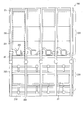
- FIG. 6 is a plan view schematically showing the arrangement of each optical sensor 231 when two types of optical sensors 231 are used as the optical sensor 231 shown in FIG.
- the liquid crystal panel 200 shown in FIG. 6 includes a half-input recognition optical sensor (hereinafter referred to as “half-input sensor”) 233 and an input recognition optical sensor (hereinafter “input”) as the optical sensor 231 in one pixel. 234) (denoted as “sensor for use”).
- half-input sensor hereinafter referred to as “half-input sensor”
- input input recognition optical sensor
- optical sensor 231 when the half-input sensor 233 and the input sensor 234 are not distinguished, the half-input sensor 233 and the input sensor 234 are collectively referred to as “optical sensor 231”.
- the half-input sensor 233 and the input sensor 234 are mixed in an appropriate distribution in the display area of the liquid crystal panel 200.
- the half-input sensor 233 and the input sensor 234 are alternately (checked) so that the pixel 210 provided with the half-input sensor 233 and the pixel 210 provided with the input sensor 234 are adjacent to each other.
- Example are arranged differently from each other.
- the transmittance can be kept equal to that of an existing in-cell photosensor panel.
- the liquid crystal panel 200 can be manufactured without increasing the number of steps compared to the existing manufacturing process of the in-cell photosensor panel. Therefore, the liquid crystal panel 200 can be manufactured without increasing tact time and cost.
- the half-input sensor 233 and the input sensor 234 can be optical sensors having the same structure. Further, as the half-input sensor 233 dedicated to recognition of half-input, an optical sensor having the same film structure as the input sensor 234 and having a different shape and thickness of each film may be used as a pixel parameter.
- the difference between the half-input sensor 233 and the input sensor 234 is that the thresholds at which sensing is turned on are different.
- the determination of the ON state of each optical sensor 231 may be performed by calculation from the photocurrent in each optical sensor 231 or may be performed by outputting an ON signal from each optical sensor 231.
- the operator side is described as the front side (upper side), and the opposite side is described as the back side (lower side).
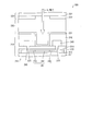
- FIG. 7 is a cross-sectional view showing a schematic configuration of a main part of the liquid crystal panel 200 when a visible light sensor is used as the optical sensor 231.
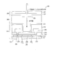
- FIG. 8 and FIG. 9 are cross-sectional views each showing a schematic configuration of a main part of the liquid crystal panel 200 when an infrared sensor is used as the optical sensor 231.
- the liquid crystal panel 200 has a configuration in which a liquid crystal layer 330 is sandwiched as a display medium layer between an active matrix substrate 310 and a counter substrate 320.
- the active matrix substrate 310 has a configuration in which an optical sensor 231, a pixel electrode 221, a switching element (not shown) (see TFT 222) and the like are provided on an insulating substrate 311 such as a glass substrate.
- polarizing plates (a front-side polarizing plate and a back-side polarizing plate) (not shown) are provided on the surfaces of the active matrix substrate 310 and the counter substrate 320 opposite to each other, as necessary.
- a retardation plate (not shown) may be provided between at least one of the front side polarizing plate and the active matrix substrate 310 and between the back side polarizing plate and the counter substrate 320 as necessary.
- the front side polarizing plate When the front side polarizing plate is provided on the surface side of the liquid crystal panel 200, the front side polarizing plate can function as a touch panel. However, it is not limited to this, You may provide another light-guide plate on a front side polarizing plate.
- a protective plate (not shown) may be provided on the surface side of the liquid crystal panel 200, and the surface of the protective plate may be used as the touch surface of the touch panel.
- a protective plate for example, a protective plate made of transparent resin, glass or the like is used.
- the liquid crystal panel 200 includes the optical sensor 231 for each pixel as an in-cell photo sensor.
- the liquid crystal panel 200 detects the coordinate position of the operator's finger on the display screen 110 (see FIG. 5) by detecting the intensity (light reception amount) of the light received by the optical sensor 231.
- the optical sensor 231 a case where a photodiode including a thin film diode having a PIN structure as a semiconductor layer is used as the optical sensor 231 will be described as an example.
- the present embodiment is not limited to this, and various existing optical sensors can be used.
- a case where a top gate type TFT is used as the TFT 222 will be described as an example.
- this embodiment is not limited to this, and a bottom-gate TFT may be used.
- a light shielding layer 312 is partially provided on the insulating substrate 311.
- a base insulating film (not shown) is provided on the insulating substrate 311 as needed so as to cover the light shielding layer 312.
- the semiconductor layer 241 of the optical sensor 231 is disposed on the insulating substrate 311 via the light shielding layer 312 and a base insulating film (not shown).
- the light shielding layer 312 and the semiconductor layer 241 are formed in an island shape.
- the semiconductor layer 241 includes a p-layer 242 (p-type semiconductor layer) and an n-layer 243 (n-type semiconductor layer), and an i-layer 244 (a semiconductor layer or intrinsic semiconductor layer having a lower impurity concentration than the p-type semiconductor and the n-type semiconductor). ) Is sandwiched.
- the semiconductor layer 241 has the PIN structure as described above, the photosensitivity of the photosensor 231 can be improved. Therefore, the sensing accuracy of the optical sensor 231 can be further improved.
- the optical sensor 231 generates a current (photocurrent) corresponding to the intensity (light quantity) of light incident on the i layer 244. That is, in the optical sensor 231, the i layer 244 functions as a light receiving region.
- the light shielding layer 312 is preferably formed on the back side of the optical sensor 231 so as to cover at least the i layer 244. Thereby, it can prevent that the optical sensor 231 detects the light emitted from the backlight.
- the semiconductor layer 241 of the optical sensor 231 is formed in the same layer as the semiconductor layer (not shown) of the TFT 222. That is, the TFT 222 is stacked on the insulating substrate 311 in a region where the light shielding layer 312 is not provided via the base insulating film.
- the semiconductor layer 241 of the optical sensor 231 and the semiconductor layer of the TFT 222 are covered with the same gate insulating film 313.
- a gate electrode On the gate insulating film 313, a gate electrode, a gate wiring 201 (see FIG. 4), a storage capacitor wiring 203 (see FIG. 4), and the like (not shown) are formed.
- the semiconductor layer 241 and the gate electrode are covered with a first interlayer insulating film 314 formed on the gate insulating film 313.
- the first interlayer insulating film 314 is an inorganic insulating film such as a silicon oxide film or a silicon nitride film.
- the p layer 242 and the n layer 243 are connected to the electrode 245 through the contact hole 315 provided in the first interlayer insulating film 314.
- the source region and the drain region of the TFT 222 are connected to a source electrode and a drain electrode (not shown) through contact holes (not shown) provided in the first interlayer insulating film 314.
- the source electrode and the drain electrode are covered with a second interlayer insulating film 316 formed on the first interlayer insulating film 314.
- An organic insulating film such as an acrylic resin is used for the second interlayer insulating film 316.
- the pixel electrode 221 is patterned as shown in FIG.
- the counter substrate 320 has a configuration in which a light shielding film 322, a display color filter and black matrix (not shown), a counter electrode, and the like are provided on a surface of the insulating substrate 321 such as a glass substrate facing the active matrix substrate 310. Have.
- the light shielding film 322 is formed of the same material as a black matrix (not shown) provided in the pixel unit 220 at the same time.
- the light shielding film 322 is formed in a shape corresponding to the position of the pixel electrode 221 and the optical sensor 231 formed on the active matrix substrate 310 side and the pattern shape of each wiring.
- the light shielding film 322 is provided in a region excluding the i layer 244 serving as a light receiving region, so that visible light can be prevented from being incident on portions other than the i layer 244.
- the optical sensor 231 when the optical sensor 231 is a visible light sensor, the optical sensor 231 is formed as a light receiving element having sensitivity to visible light. When the optical sensor 231 is a visible light sensor, the optical sensor 231 senses all visible light. Such an optical sensor 231 is inferior in sensing ability in an environment where ambient light is dark such as indoors.
- the optical sensor 231 is formed as a light receiving element having sensitivity to infrared light.
- Such an optical sensor 231 senses reflected light of infrared light included in the backlight. For this reason, it is preferably used in an environment where ambient light is dark.
- a light shielding body that shields (reflects) light having a specific frequency component at least at a position facing the i layer 244 of the optical sensor 231. 323 is formed.
- the light shield 323 may be disposed on the optical sensor 231 in the active matrix substrate 310, or may be provided on the counter substrate 320 as shown in FIGS.
- FIG. 8 shows an example in which an optical filter having a stacked structure of a red (R) color filter 324R and a blue (B) color filter 324B is used as the light shielding body 323.
- the visible light component visible light wavelength
- the optical sensor 231 photoelectrically converts infrared light transmitted through the light shielding body 323.
- FIG. 8 illustrates the case where the light shield 323 includes the RB color filters 324R and 324B as described above, the present embodiment is not limited to this.
- the light-shielding body 323 only needs to be able to block visible light components, and may have a laminated structure of an R color filter 324R and a green (G) color filter (not shown). You may have a laminated structure of the filter 324B and the G color filter (not shown). Moreover, it is not limited to a two-layer structure, and may have a three-layer structure of RGB. When the light shield 323 has a three-layer structure of RGB color filters, the average visible light transmittance can be suppressed to less than 1%.
- the light shielding body 323 is not limited to the optical filter formed of the color filter laminate as described above, and may be an IR resist that transmits only infrared light as shown in FIG.
- a thermoresist is known as an IR resist.
- a resist of a fourth color that is, a color other than RGB that blocks visible light and transmits only infrared light is used.
- the light shield 323 when the light shield 323 is an optical filter formed by stacking a plurality of color filters, the light shield 323 can be simultaneously formed using the same material as the display color filter of the pixel portion 220. It becomes. For this reason, cost can be reduced compared with the case where the light-shielding body 323 is manufactured by another material and another process.
- the light sensor 231 has been described as an example.
- the present embodiment is not limited thereto. is not.
- the optical sensor 231 may be designed to be sensitive to ultraviolet light.
- the optical sensor 231 and the liquid crystal panel 200 an existing optical sensor and an in-cell photo panel can be used as described above. Therefore, the material and film thickness of each layer can be set in the same manner as in the past. Therefore, in the present embodiment, description of the manufacturing method of the liquid crystal panel 200 and the optical sensor 231 and the material and film thickness of each layer are omitted.
- the state determination unit 2 determines that the input state is when the operator's finger or object is in contact with the display screen 110 over a certain area. Further, when the operator's finger or object is in contact with the display screen 110 less than the predetermined area and the distance in the normal direction (Z-axis direction) between the operator's finger or object and the display screen 110 is When the operator's finger or object is not in contact with the display screen 110 within a certain distance, it is determined as a half-input state. Then, it is determined as a non-input state when the operator's finger or object is separated from the display screen 110 in the normal direction by more than the predetermined distance.
- the display screen 110 is in contact with the display screen 110 more than or less than a certain area is associated with the input button 101 displayed on the display screen 110 (that is, the display area of the input button 101 or the like). It is shown that it is in contact with more than a certain area or less than a certain area.
- the normal direction indicates a direction perpendicular to the display screen 110 (that is, a direction perpendicular to the substrate surface of the liquid crystal panel 200).
- 10A to 10C are diagrams showing the relationship between the distance between the display screen 110 of the display unit 11 and the fingertip of the operator, and the shade of the shade that can be generated according to the distance.
- FIG. 11 is a graph showing the relationship between the distance Q and the amount of light entering the optical sensor 231 (the amount of received light).
- the input button 101 that the operator is trying to touch can be detected.
- the distance between the input button 101 and the fingertip of the operator that is, the distance Q between the display screen 110 in the display area of the input button 101 and the fingertip of the operator) can be detected.
- the area where the operator's finger pad contacts the display screen 110 differs depending on whether the operator touches the display screen 110 lightly with a fingertip or strongly.
- the distance from the display screen 110 at which a part of the fingertip of the operator contacts the display screen 110 is B (0 ⁇ B ⁇ A)
- the display screen 110 of the display unit 11 and the fingertip of the operator When the distance Q is within B (B ⁇ Q), the amount of light entering the half input sensor 233 and the input sensor 234 in the region where B ⁇ Q is L2 (L2 ⁇ L1) as shown in FIG. It becomes as follows.
- the threshold value at which the half-input sensor 233 is turned on is L1 (first threshold value)
- the threshold value at which the input sensor 234 is turned on is L2 (second threshold value)
- the photocurrent output from each photosensor 231 or The state of the input button 101 can be detected by detecting (extracting) the optical sensor 231 in the ON state based on the ON signal.
- the slope of the curve shown in FIG. 11, that is, the threshold value is entered into each optical sensor 231 by changing pixel parameters such as the shape and thickness of each film constituting the half-input sensor 233 and the input sensor 234. It can be changed by manipulating the amount of light.
- Examples of the pixel parameters include the shape of a semiconductor pattern (Si shape) of the optical sensor 231; the shape of a light shielding film 322 or a light shielding body 323, a light shielding black matrix, a color filter, a light shielding resist pattern, or the like; Examples include the shape and thickness of (especially the second interlayer insulating film 316). By changing such pixel parameters, the light receiving area of the optical sensor 231 can be changed.
- the pixel parameters include the TFT channel length (L length), channel width (W length), Lov region length in the channel length direction (Lov length), and Loff region.
- the Loff region is a region where an LDD (Lightly doped drain) region is not disposed so as to overlap the gate electrode through the gate insulating film
- the Lov region is the gate electrode through which the LDD region is disposed through the gate insulating film. Indicates an area that overlaps with.
- the sensitivity increases when the amount of light entering the optical sensor 231 increases, but the noise also increases, so it is desirable to adjust the balance.
- the pixel parameter is, for example, when the sensing of the half-input sensor 233 is ON when it is as dark as the shadow of a hand, and the input sensor 234 is finally dark when the display screen 110 is touched. It is preferable to adjust so that the sensing of is turned on.
- FIG. 12 is a flowchart showing the flow of touch operation processing by the state determination unit 2 and the information processing unit 3.
- the state determination unit 2 extracts the optical sensor 231 whose light amount entering the optical sensor 231 is equal to or less than L1 (first threshold) in the display unit 11, and compares it with the ambient illuminance by the shadow 401 of the finger or hand. Then, a region where the illuminance is low is sensed, and coordinates on the display screen 110 such as a finger in the sensing region are detected (calculated) (step S1).
- L1 first threshold
- the extraction of the optical sensor 231 in which the amount of light entering the optical sensor 231 is equal to or less than L1 (first threshold) is performed by extracting the ON-state optical sensor 231 (that is, the ON-state half-input sensor 233). .
- a display area when each input button 101 is displayed for each input button 101 is defined by XY coordinates on the display screen 110.
- the coordinate value indicating the display area of each input button 101 is stored in the storage unit 15, and it is determined that the input button 101 in the area corresponding to the detected coordinate is the input button 101 to be touched. Is done.
- the coordinate values stored in the storage unit 15 need only be able to determine the display area of each input button 101, and it is not necessary to store all the coordinates in the display area of each input button 101.
- it may be a coordinate value indicating the outer frame (ruled line frame) of each input button 101, or the upper left and lower right coordinates of the ruled line frame.
- the state determination unit 2 includes an input button 101 including coordinates detected from the coordinate data stored in the storage unit 15 (that is, the input button 101 corresponding to a region where the illuminance is lower than the ambient illuminance). Is detected (step S2).
- the amount of received light is equal to or less than L2 (second threshold) in the display area corresponding to the detected half-input sensor 233 (that is, in the display area of the detected input button 101).
- L2 second threshold
- the number of optical sensors 231 (input sensors 234) is extracted (step S3).
- the state determination unit 2 determines whether or not the number of optical sensors 231 (input sensors 234) extracted in step S3 is a predetermined number (for example, N or more, 0 ⁇ N) or more (step). S4). When it is determined that the number is N or more, the information processing section 3 performs input processing on the input button 101 (step S5).
- step S4 when it is determined in step S4 that the number is less than N, the number of half-input sensors 233 in which the amount of received light is equal to or less than L1 (first threshold) in the display area of the input button 101 detected in step S2. Is extracted (step S6).
- step S6 it is determined whether or not the number of half-input sensors 233 extracted in step S6 is a predetermined number (for example, M, 0 ⁇ M) or more (step S7).
- a predetermined number for example, M, 0 ⁇ M
- step S8 half-input processing for the input button 101 is performed.
- step S7 when it is determined in step S7 that the number is less than M, the process proceeds to step S1.
- N and M are the size of the input button 101, the type of coordinate detection object on the display screen 110 (that is, the input button 101 such as an operator's finger, touch pen, etc.), the input button 101 is appropriately set according to the half-input / input function associated with 101.
- the operator confirms the input button 101 on which the half-input processing is performed, if the finger is moved away from the display screen 110 or is slid, the operator returns to the non-input state or another input is performed. A new half-input process for the button 101 is performed. Further, while the operator confirms the input button 101 on which the half-input process is being performed, the half-input process on the input button 101 being confirmed is repeatedly performed. For this reason, the half-input processing state is maintained (continued).
- the state determination unit 2 first, the number of the half-input sensors 233 and the input sensors 234 that are turned on when the operator's finger or the like is brought close to or in contact with the display screen 110, and From the coordinates, a region where the illuminance is lower than the ambient illuminance (region where the half-input sensor 233 is turned on) is sensed, and the coordinates of the fingertip and the like are calculated by the program in the sensing region.
- the input button 101 to be touched is detected from these coordinates, and when it is determined that the input button 101 is in a half-input state, the input button 101 is associated with the input button 101 such as enlarging the input button 101. Execute half-input function (half-input processing).
- an area where the illuminance is lower than that of the surrounding illuminance due to the shadow of the fingertip or the like (area where the input sensor 234 is turned on by a predetermined number or more) is detected, and the input button 101 to be touched is determined to be in the input state
- the display area of the input button is recognized as a signal input area.
- a half-input process can be executed before the input process by bringing a finger or the like close to or lightly touching the input button 101. For this reason, the operator can perform input processing after confirming the type or function of the input button 101 to be input. For this reason, accurate input processing can be performed. Further, it is possible to avoid erroneous input when an operator or an object accidentally touches the display screen 110 as in Patent Documents 2 to 5. In particular, in Patent Documents 2 to 4, the input process is always executed after the half-input process is performed. However, according to the present embodiment, only the half-input process can be executed. For this reason, convenience is high.
- each state described above is recognized according to the amount of light entering the optical sensor 231 and the contact area with respect to the display screen 110. It is not necessary to repeat the same operation. For this reason, operativity can be improved rather than before.
- a half-input function such as enlargement of the input button 101 and explanation of functions can be executed simply by bringing a finger close to or touching the display screen 110, an input operation can be performed smoothly.
- the number of photosensors 231 (input sensor 234) that is equal to or less than the second threshold is extracted from the number of photosensors 231 that are equal to or less than the first threshold (for half-input). Prior to the extraction of the number of sensors 233). That is, the determination of the input state is performed prior to the determination of the half-input state.
- the half-input process does not necessarily have to be executed. It is also possible for an operator who does not need to explain the input keys or an operator familiar with soft keys to execute only the input process by pressing the input button 101 before the half-input process is executed.
- the distances A and B in other words, the light amounts L1 and L2
- desired processing according to the pressing speed of the operator it is possible to perform desired processing according to the pressing speed of the operator by appropriately adjusting the time until the half-input processing is executed using a timer or the like (not shown). Needless to say.
- the input state and the half-input state are temporarily pressed. Even if the pressure is constant, the input state and the half-input state can be distinguished.
- each state described above can be recognized from the amount of light entering the optical sensor 231 and the contact area with respect to the display screen 110. In order to make a determination, it is not necessary to provide a separate sensor outside the display panel.
- Patent Document 5 an optical sensor is provided on a frame surrounding the upper surface of the touch panel.
- the optical sensor is provided outside the display panel as described above, there are problems that the thickness of the product is increased and the design of the product is restricted.
- a separate process for attaching the optical sensor to the outside of the display panel is necessary, which leads to an increase in the number of parts, resulting in an increase in manufacturing costs.
- the liquid sensor panel 200 can be used as an optical sensor.
- the above state can be determined using only the optical sensor 231. Therefore, the product can be made thinner and lighter, and sensor parts other than the optical sensor 231 need not be purchased and attached, so that an increase in manufacturing time and cost can be avoided.
- a sensor element such as an optical sensor
- a demerit such as an increase in the outer shape of the panel
- it has an auxiliary role (for example, S / N ratio improvement).
- a sensor element such as an optical sensor may be separately provided outside the liquid crystal panel 200.
- the function associated with the input state indicates, for example, execution of input of the touched input button 101.
- the input button 101 is a numeric keypad
- the input corresponding to the touched numeric keypad is a display of numbers, operators, computations, computation results, and the like.
- the input button 101 is an icon, it is touched. For example, starting and executing a program indicated by an icon.
- the function associated with the half-input state may be a function other than the function associated with the input state of the input button 101, and different processing results are obtained between the input state and the half-input state. It only has to be done.
- the functions associated with the half-input state mainly include functions other than execution of input.
- FIG. 13 are diagrams showing an example of half-input processing.
- FIG. 13 shows a case where the color of the input button 101 is reversed in the half-input state.
- FIG. 13B shows a case where the input button 101 is enlarged in a half-input state.
- FIG. 13C illustrates a case where the pointer is displayed in a half-input state.
- FIG. 13D shows a case where the color of the input button 101 is reversed and a pointer is displayed in the half-input state.
- the half-input function includes, for example, (a) color inversion and marking of the input button 101 that is currently pointing, and (b) zoom (enlarged / reduced display of the input button 101 to be executed, such as numbers and characters). (Enlargement / reduction processing), (c) display of a pointer indicating the input button 101 to be input, (d) provision of information associated with the input button 101 to be input by voice or message, (e) game
- the input button 101 may be input or output in a musical instrument application or the like.
- the input button 101 to be input refers to the input button 101 determined (determined) by the state determining unit 2 as a half-input state.
- the input strength of the input button 101 indicates that the input button 101 is input with a weaker input strength than the input strength of the input button 101 performed in the input processing in the half-input processing. As a result, for example, in musical instrument applications, it is possible to perform performances with strengths.
- the information associated with the input button 101 to be input may be the type of the input button 101 to be input, or may be an explanation accompanying the input button 101 to be input.
- the numeric keypad to be input may be read aloud as voice provision of information associated with the input button 101 to be input.
- the input button 101 is an icon, it may be a notification of the type of icon to be input, or may be a detailed description of the function or the like of the icon to be input.
- the pointer when the pointer is displayed on the display screen 110 as a function associated with the half-input state, the pointer is displayed so as not to overlap the operator's finger. Further, when a pointer is displayed on the display screen 110, the pointer selection area indicating the input location may be set smaller as the operator's finger or object approaches the display screen 110.
- an image displayed on the display screen 110 with a certain size may be enlarged around a position where a signal is input in a half-input state. Then, when a finger or the like is brought close to or slightly touched the display screen 110 so that the input button 101 to be executed can be selected smoothly, an image near the finger or object is compared with the ambient illuminance. Thus, the input button 101 and the surrounding input buttons 101 may be displayed in an enlarged manner with the input button 101 in the region with the lowest illuminance as the center.
- the number of input buttons 101 that are enlarged and displayed as the operator's finger or object approaches the display screen 110 may be set in accordance with the magnitude of the photocurrent output from the display screen 110.
- half-input processing for example, processing that makes it easy to determine or select an input location by changing the display of a certain region including the detected input button 101 to be distinguishable from other regions. Is mentioned.
- the state determination unit 2 (A) does not contact the input button 101 (non-contact within a certain distance A), and (B) Different signals may be output to the second information processing unit 32 depending on the contact state within a certain area.
- the second information processing unit 32 may execute different half-input processes associated with each state depending on whether the state is the state (A) or the state (B). it can.
- the second information processing unit 32 may add a different function depending on the elapsed time since it is determined as the half-input state, such as switching from color reversal of the input button 101 to explanation display.
- a contact state within a certain area or less can be determined as a half-input state, and thus the display device has the same function as a half-press by a conventional hard key. be able to.
- a known half-press function using a hard key is replaced with the half-input function as a half-input function executed by the second information processing unit according to the determination result of the state determination unit 2. Or may be additionally executed.
- the present embodiment as described above, the case where the half-input sensor 233 is provided separately from the input sensor 234 has been described as an example. However, the present embodiment is not limited to this.
- FIG. 14 is another plan view schematically showing the arrangement of each optical sensor 231 when two types of optical sensors 231 are used as the optical sensor 231 shown in FIG. 4, that is, a half-input sensor 233 and an input sensor 234. is there.
- two optical sensors 231, that is, a half-input sensor 233 and an input sensor 234 are arranged as one optical sensor 231.
- the pixels 210 are all formed in the same pattern as shown in FIG.
- the resolution of the optical sensor 231 can be increased.
- optical sensor 231 the case where two types of optical sensors (half-input sensor 233 and input sensor 234) having different threshold values for sensing are used as the optical sensor 231 has been described as an example.
- the present embodiment is not limited to this.
- an existing optical sensor is used as the optical sensor 231, and the light reception amount of the optical sensor 231 is compared with the first threshold value (L1) and the second threshold value (L2) to perform a non-input state, a half-pressed state, an input
- the state may be determined by the state determination unit 2. That is, the value of the photocurrent output according to the amount of light received by the optical sensor 231 and the value of the photocurrent output when the amount of light received by the optical sensor 231 is the first threshold (L1) and the second threshold (L2), respectively.
- the above state may be determined by performing a comparison operation.
- the distance Q> the distance A that is, the amount of received light> L1
- the distance B that is, L1 ⁇ the amount of received light> L2
- the distance B ⁇ distance Q that is, L2 ⁇ the amount of received light
- a mobile phone has been described as an example of a display device.
- the display device is not limited to a mobile phone, and can be applied to various display devices in which a display unit and an input unit are integrated, or an electronic apparatus including such a display device.
- Examples of such display devices and electronic devices include various mobile terminals such as mobile phones, PHS (Personal Handyphone System), and PDA (Personal Digital Assistants).
- PHS Personal Handyphone System
- PDA Personal Digital Assistants
- an in-car car navigation device an audio device, a DVD (Digital Versatile Disc) playback device, a television device, a game machine, a music player device, or a composite electronic device that combines the functions of these devices.
- the present invention can also be suitably applied.
- a touch panel integrated display panel is used as the display unit 11
- this embodiment is not limited to this, and may include a display panel and a touch panel provided over the display panel.
- a liquid crystal panel has been described as an example of a display panel.
- this embodiment is not limited to this, and may be a display panel using electroluminescence (EL), for example. That is, the display device according to the present embodiment is not limited to the liquid crystal display device, and may be an EL display device or the like.
- EL electroluminescence
- liquid crystal panel having features such as thinness and light weight as the display panel can improve portability.
- the display device described above determines the input state when the display panel that displays the input button on the display screen, and when the operator's finger or object is in contact with the input button for a certain area or more.
- the state determination unit determines whether the operator's finger or object is in contact with the input button below the specified area, and when the normal direction distance between the operator's finger or object and the input button is within a certain distance and is not in contact.
- the state determination unit And an information processing unit that executes a function associated with the state of the input button according to the state of the input button.
- the display device includes an optical sensor for each pixel in the display panel, and a distance in a normal direction between an operator's finger or object and the input button is the fixed distance.
- the state determination unit The number of photosensors in which the amount of light received by the photosensor in the region associated with the input button including the finger or object coordinates of the operator is L1 or less is M (where 0 ⁇ M) or more, and When the number of photosensors in which the amount of light received by the photosensors in the region is less than or equal to L2 is less than N (however, 0 ⁇ N), it is determined as a half-input state, and the amount of light received by the photosensors in the region is L2. When the number of optical sensors below is N or more It is determined that the input state.
- the information processing unit includes M or more photosensors in which the amount of light received by the photosensor in the region associated with the input button including the operator's finger or object coordinates on the display screen is L1 or less.
- the execution of the function associated with the half-input state of the input button is started, and the amount of light received by the photosensor in the region associated with the input button for which the half-input function is performed is L2 or less.
- the number of photosensors becomes N or more, the function associated with the input state of the input button is executed.
- each state described above can be recognized from the amount of light received by the optical sensor provided in the display panel and the contact area of the operator's finger or object with the display screen. Therefore, it is possible to determine the above state without providing a separate sensor outside the display panel. For this reason, it is possible to reduce the thickness and weight of the product, and it is not necessary to purchase and attach sensor parts other than the above-described optical sensor, so that an increase in manufacturing time and cost can be avoided.
- the display device includes, as the optical sensor, an input sensor for determining that the amount of received light is L2 or less and a half-input sensor for determining that the amount of received light is L1 or less.
- the optical sensor an input sensor for determining that the amount of received light is L2 or less and a half-input sensor for determining that the amount of received light is L1 or less.
- the transmittance can be kept equal to that of the existing display panel.
- the liquid crystal panel can be manufactured without increasing the number of steps with respect to an existing display panel manufacturing process in which an optical sensor is provided in the display panel. For this reason, the display device can be manufactured without increasing the tact time and cost.
- the display device has, as the optical sensor, an input sensor for determining that the amount of received light is L2 or less and a half input for determining that the amount of received light is L1 or less in one pixel. It is preferable that a sensor is provided.
- the resolution of the optical sensor can be increased by providing the input sensor and the half-input sensor in one pixel.
- the display device includes, as the optical sensor, an input sensor for determining that the amount of received light is L2 or less, and a half-input sensor for determining that the amount of received light is L1 or less.
- a pixel in which only one of the input sensor and the half-input sensor is provided in one pixel and a pixel in which the input sensor and the half-input sensor are provided in one pixel are mixed. It is preferable that
- the present invention relates to various portable terminals, in-vehicle car navigation devices, audio devices, DVD (Digital Versatile Disc) playback devices, television devices, game machines, music player devices, or a combination of these devices. It can be suitably used for a display device having a touch panel function, such as a type electronic device, and an electronic device using the display device.
- a display device having a touch panel function such as a type electronic device, and an electronic device using the display device.
Landscapes
- Engineering & Computer Science (AREA)
- General Engineering & Computer Science (AREA)
- Theoretical Computer Science (AREA)
- Human Computer Interaction (AREA)
- Physics & Mathematics (AREA)
- General Physics & Mathematics (AREA)
- Position Input By Displaying (AREA)
Abstract
携帯電話機(100)は、表示パネルを表示部(11)として備えているとともに、状態判別部(2)と情報処理部(3)とを備えている。状態判別部(2)は、操作者の指または物体が入力ボタンに一定面積以上接触しているときを入力状態と判別し、操作者の指または物体が入力ボタンに上記一定面積未満接触しているとき、および、操作者の指または物体と入力ボタンとの間の法線方向の距離が一定距離以内でかつ非接触であるときを半入力状態と判別し、操作者の指または物体が入力ボタンに対し法線方向に上記一定距離よりも離れているときを非入力状態と判別する。情報処理部(3)は、状態判別部(2)で判別された入力ボタンの状態に応じて、該入力ボタンの状態に対応付けられた機能を実行する。
Description
本発明はタッチパネル機能を備えた表示装置に関するものである。
近年、装置の小型化を図るため、表示部と入力部とが一体化された表示装置が広く普及している。特に、携帯電話機、PDA(Personal Digital Assistants)、ノート型PC(personal computer)等の携帯端末では、指やタッチペン等で表示画面に触れることにより操作可能なタッチパネル付きの表示装置の搭載が主流となりつつある。
このような表示装置は、入力部としてタッチパネルを備え、操作者が、タッチパネルの表示画面に表示された種々の入力ボタンをタッチすることで、タッチされた入力ボタンに対応付けられた機能を実行する。このようにソフトウェアを用いた入力ボタンは、表示部とは別にハードウェアに設けられた機構的な入力ボタンをハードキーと呼ぶのに対し、ソフトキーと呼ばれている。
しかしながら、携帯電話機やPDA等の小型の携帯情報端末に用いられる表示装置では、表示部も比較的小さくなる。このため、表示画面に表示される個々の入力ボタンの大きさも自ずと小さくなる。
しかしながら、例えばタッチパネルを指で操作する場合、表示された入力ボタンが指と比較して小さいと、実際に押される入力ボタンの確認が困難になる。このため、操作者は、本当に所望の入力ボタンを押せたのか、誤って近接した別の入力ボタンを押していないか、が気になり、スムーズに操作できないことがある。
ハードキーを用いたプッシュボタン方式の携帯電話機の入力ボタンには一般的に凹凸が設けられている。操作者は、入力されない程度の軽い押圧によってそれぞれの入力ボタンの凹凸を認識し、所望の入力ボタンを確認した後プッシュする。
ところが、タッチパネル式の携帯情報端末には、入力ボタンにハードキーを用いた場合のような凹凸がない。このため、入力ボタンを押す前に入力ボタンの認識ができず、違和感を覚える。特に、タッチパネル操作に不慣れな操作者にとっては、違和感が大きい。
そこで、このような問題点に対し、種々の提案がなされている。
特許文献1には、タッチパネルを2度指でタッチすることにより入力を行うことが開示されている。特許文献1では、1回目のタッチでタッチ座標の周辺の入力ボタンを再配列して拡大表示し、2度目のタッチでタッチ座標の入力ボタンが押下されたものと判定する。
また、特許文献2~4には、タッチパネルをタッチすることでタッチ座標の周辺の入力ボタンを拡大表示し、指を離すことで入力を行うことが開示されている。特許文献2~4では、指を離すと、直前にタッチされていた座標データと表示画面に拡大表示されている入力ボタンの表示位置とに基づいて、直前にタッチされていた座標データの入力ボタンが押下されたものと判定する。
また、特許文献5には、表示入力部に指等の位置を検出するセンサを設け、該センサで検出された指等の位置に対応する表示パネル上の入力ボタンに触れたときに行う処理の内容を、操作者が入力ボタンに触れる前に表示や音声で提供することが開示されている。特許文献5では、非接触状態で表示ボタンの選択および情報提供を行い、操作者が入力ボタンに触れることで、入力ボタンによる処理の実行が行われる。
しかしながら、特許文献1に記載の技術は、入力の確定のためには必ず2度のタッチを必要とする。しかも、1度タッチパネルにタッチした後、拡大表示されるのを待って再度タッチする必要がある。このため、二度手間になって操作性が悪い。
また、特許文献2~4に記載の技術では、タッチで拡大表示した後は、タッチパネルから指を離すと入力が実行されてしまう。このため、誤って一瞬だけタッチパネルに触れてしまったような場合でも、入力が実行されてしまう。また、一旦タッチパネルに触れてしまうと、指を離すと入力が確定されてしまうため、タッチパネルに触れたまま指を移動させる必要がある。
逆に、特許文献5では、入力ボタンに少しでも触れてしまうと入力が実行されてしまう。このため、指やタッチペン等を近づけるつもりでその先端がうっかりタッチパネルに触れてしまったような場合でも、入力が実行されてしまう。
本発明は、上記問題点に鑑みなされたものであり、その目的は、表示画面に指や物体を近づけたり若干触れたりすることで入力ボタンを通常通りタッチしたときとは異なる機能を実行させることができる、利便性の高い表示装置を提供することを目的とする。
上記の課題を解決するために、表示装置は、入力ボタンを表示画面に表示させる表示パネルと、操作者の指または物体が上記入力ボタンに一定面積以上接触しているときを入力状態と判別し、操作者の指または物体が入力ボタンに上記一定面積未満接触しているとき、および、操作者の指または物体と入力ボタンとの間の法線方向の距離が一定距離以内でかつ非接触であるときを半入力状態と判別し、操作者の指または物体が入力ボタンに対し法線方向に上記一定距離よりも離れているときを非入力状態と判別する状態判別部と、上記状態判別部で判別された入力ボタンの状態に応じて、該入力ボタンの状態に対応付けられた機能を実行する情報処理部とを備えている構成を有している。
上記の構成によれば、操作者が入力ボタンに指等を近づけた場合だけでなく、入力ボタンに軽く接触した場合にも、上記入力ボタンは半入力状態にあると判別される。
このため、操作者は、ソフトキーに慣れていない場合であっても、ハードキーの半押しと同様に操作を行うことができる。
ここで、入力ボタンが入力状態であると判別されたときに実行される上記入力ボタンに対応付けられた機能を入力機能と称し、その実行を入力処理と称する。また、入力ボタンが半入力状態であると判別されたときに実行される上記入力ボタンに対応付けられた機能を半入力機能と称し、その実行を半入力処理と称する。また、ここでいう機能の実行とは、入力ボタンに対応付けられた機能を実行するための処理プログラムの実行を意味する。
特許文献2~4では、入力ボタンに操作者の指等が触れた場合、入力ボタンに操作者の指等が触れることで、あるいは、入力ボタンに操作者の指等が触れた後で指を離すことで入力処理が実行される。このため、特許文献2~4では、半入力処理を行った後は必ず入力処理が実行されてしまう。しかしながら、上記の構成によれば、入力ボタンに操作者の指等が触れた後でも半入力処理のみを実行することができる。このため、利便性が高い。
また、上記の構成によれば、入力ボタンに指等を近づけたり軽く接触させたりすることで、入力ボタンの入力処理が行われる前に半入力処理を実行させることができる。したがって、特許文献1のように入力処理を行うために同じ動作を繰り返し行う必要はない。このため、操作性を向上させることができる。
また、入力ボタンに指等を近づけたり少し触れたりするだけで半入力処理を実行させることができるので、操作者は、入力しようとしている入力ボタンに対し、該入力ボタンに対応付けられた半入力機能の実行結果を確認した後に入力ボタンを押下して入力機能を実行させることができる。このため、正確な入力処理を行うことができるとともに、操作者による半入力処理の確認、並びに、その後の入力処理をスムーズに行うことができる。
したがって、上記の構成によれば、表示画面に指や物体を近づけたり若干触れたりすることで入力ボタンを通常通りタッチしたときとは異なる機能を実行させることができる、利便性の高い表示装置を提供することができる。
以上のように、上記表示装置では、上記状態判別部が、操作者の指または物体が上記入力ボタンに一定面積以上接触しているときを入力状態と判別し、操作者の指または物体が入力ボタンに上記一定面積未満接触しているとき、および、操作者の指または物体と入力ボタンとの間の法線方向の距離が一定距離以内でかつ非接触であるときを半入力状態と判別し、操作者の指または物体が入力ボタンに対し法線方向に上記一定距離よりも離れているときを非入力状態と判別することで、ハードキーによる半押しに相当する半入力機能を、ソフトキーによる入力ボタンで実現させることができる。
したがって、上記表示装置によれば、操作者がソフトキーに慣れていない場合であっても、ハードキーの半押しと同様に操作を行うことができる。また、入力ボタンに操作者の指等が触れた後でも半入力処理のみを実行することができる。このため、利便性が高い。
また、入力処理を行うために同じ動作を繰り返し行う必要はない。このため、操作性を向上させることができる。
また、入力ボタンに指等を近づけたり少し触れたりするだけで半入力処理を実行させることができるので、操作者は、入力しようとしている入力ボタンに対し、該入力ボタンに対応付けられた半入力機能の実行結果を確認した後に入力ボタンを押下して入力機能を実行させることができる。このため、正確な入力処理を行うことができるとともに、操作者による半入力処理の確認、並びに、その後の入力処理をスムーズに行うことができる。
したがって、上記表示装置によれば、表示画面に指や物体を近づけたり若干触れたりすることで入力ボタンを通常通りタッチしたときとは異なる機能を実行させることができ、ハードキーによる利点とソフトキーによる利点を併せ持つ、従来にない、極めて利便性が高い表示装置を提供することができる。
実施の一形態にかかる表示装置について図1~図14に基づいて説明すれば、以下の通りである。
本実施の形態では、上記表示装置として携帯電話機を例に挙げて説明する。
〔携帯電話機の外観〕
図3の(a)・(b)は本実施の形態にかかる携帯電話機の外観を示す概略構成図であり、(a)は入力ボタンの非入力状態、(b)は入力ボタンの半入力状態を示している。なお、非入力状態とは通常状態を示し、半入力状態とは、ハードキーによる半押しに相当する状態を示す。
図3の(a)・(b)は本実施の形態にかかる携帯電話機の外観を示す概略構成図であり、(a)は入力ボタンの非入力状態、(b)は入力ボタンの半入力状態を示している。なお、非入力状態とは通常状態を示し、半入力状態とは、ハードキーによる半押しに相当する状態を示す。
図3の(a)・(b)に示す携帯電話機100の表示部11には、ソフトキーからなる入力ボタン101(機能ボタン、選択ボタン)としてテンキーが表示されている。また、上記表示部11には、入力ボタン101と併せて、入力ボタン101に対応付けられた表示を行う入力結果表示部102が表示されている。上記表示部11の表示画面110は、例えばフルフラットに形成されている。
上記表示部11は、例えば液晶パネル等の表示パネルによって構成されている。上記表示パネルは、タッチパネル機能を有するタッチパネル一体型の表示パネルであり、上記表示画面110が、タッチパネル(操作入力部)として用いられる。このため、上記表示部11は、表示部兼操作入力部として用いられる。
上記携帯電話機100は、ハードキーによる半押しに相当する半入力機能を有している。上記携帯電話機100において操作者が上記表示部11に表示された入力ボタン101を指やタッチペン等の物体でタッチすると、上記入力ボタン101の入力が実行され、上記入力ボタン101に対応付けられた機能が実行される。一方、上記入力ボタン101に指やタッチペン等の物体を近づけたり、入力が実行されない程度に軽く触れたりすることで、上記入力ボタン101に対応付けられた、入力以外の機能(半入力機能)が実行される。
以下に、上記半入力機能を実現するための構成について詳細に説明する。
なお、以下の説明では、説明の便宜上、操作者が、表示画面110を指でタッチすることで入力ボタンによる入力が行われる場合を例に挙げて説明する。
〔携帯電話機の概略構成〕
図2は、本実施の形態にかかる携帯電話機の概略構成を示すブロック図である。
図2は、本実施の形態にかかる携帯電話機の概略構成を示すブロック図である。
図2に示すように、本実施の形態にかかる携帯電話機100は、制御部1、表示部11、音声出力部12、撮像部13、センサ部14、記憶部15、アンテナ部16、通信部17、図示しない音声入力部等を備えている。
制御部1は、携帯電話機100内の各種構成を統括的に制御する。制御部1の機能は、例えば、記憶部15に記憶されたプログラムをCPU(Central Processing Unit)が実行することによって実現される。
表示部11は、制御部1からの表示信号に基づいて、画像、テキスト、動画等の内容を表示する。表示部11には、前記したように、液晶パネル等の表示パネルが用いられる。
以下、本実施の形態では、表示パネルとして、液晶パネルを用いた場合を例に挙げて説明する。表示媒体に液晶を用いた液晶パネルは、各種表示パネルのなかでも薄型で軽量かつ消費電力が小さいといった利点を有している。このため、携帯電話機等の小型の携帯端末における表示部に特に適している。
なお、本実施の形態において、上記液晶パネルの表示モードは特に限定されず、TN(Twisted Nematic)モード、IPS(In Plane Switching)モード、VA(Vertical Alignment)モード等のあらゆる表示モードを適用することができる。
液晶パネルの背面側には、必要に応じて、図示しないバックライトが設けられる。
音声出力部12は、制御部1から送られた音声信号を音波に変換して外部に出力する。音声出力部12は、例えば、スピーカ、イヤホン、音声出力用コネクタ等を備えている。
撮像部13は、制御部1からの制御信号に基づいてカメラ等による撮像を行い、画像、動画等のデータを生成する。また、撮像部13は、生成したデータを制御部1に送信する。撮像部13により撮像された写真データ等は、例えば記憶部15に記憶される。
撮像部13には、例えば、CCD(Charge Coupled Device)、CMOS(Complementary Metal-oxide Semiconductor)等の撮像素子が用いられる。
センサ部14は、タッチパネルの機能を上記液晶パネル内に持たせるためのものである。センサ部14には、表示部11の各画素に対応する複数の光センサが設けられている。
記憶部15は、各種データおよびプログラムを記憶するメモリからなる。記憶部15には、入力ボタン101の入力状態、半入力状態にそれぞれ対応付けられた機能を実行するための処理プログラムが記憶されている。
また、記憶部15には、各々の入力ボタン101に対してその入力ボタン101が表示された場合の表示領域が、表示画面110上のXY座標で定義されている。
記憶部15は、具体的には、座標記憶部、アプリケーション情報記憶部等を含んでいる。
記憶部15は、ROM(Read Only Memory)、RAM(Random Access Memory)、フラッシュROMであってもよい。上記処理プログラムは、例えば通信部17を介して書き換え可能であってもよい。
ROMには、例えば、制御部1が動作する際に必要なプログラムや制御データ等の固定データが記憶される。RAMには、例えば、通信に関するデータ、演算に使用するデータ、および演算結果等が一時的に記憶される。記憶部15には、撮像部13により撮像された写真データ等を記憶するフラッシュメモリやEEPROM等の書き換え可能な不揮発性メモリ等も含まれる。
アンテナ部16は、電波を外部に送り出すとともに外部から電波を受け取る。
通信部17は、アンテナ部16を介して外部とのデータ通信を行う。なお、上記通信は、有線による通信であってもよく、無線による通信であってもよい。通信部17では、ベースバンド信号処理、データの変復調処理、RF(Radio Frequency)処理等の各種処理が行われる。
〔制御部1の概略構成〕
次に、制御部1の概略構成について、図1を参照して以下に説明する。
次に、制御部1の概略構成について、図1を参照して以下に説明する。
図1は、本実施の形態にかかる携帯電話機100の概略構成を示すブロック図である。
制御部1は、図1に示すように、状態判別部2、情報処理部3、および機能実行部4を備えている。
状態判別部2は、センサ部14からの出力に応じて、操作者の指または物体等の対応する表示画面110上の座標を検出(算出)し、この検出した座標からタッチしようとしている入力ボタン101を検出し、検出した入力ボタン101の状態を、(1)入力状態、(2)半入力状態、(3)非入力状態の3段階で判別する。
情報処理部3は、状態判別部2で判別された状態に対応付けられた機能を実行するための処理プログラムを実行する。
情報処理部3は、第1情報処理部31および第2情報処理部32を備えている。
第1情報処理部31は、記憶部15から入力状態に対応付けられた機能(入力処理)を実行するための処理プログラムを読み込み、該処理プログラムを実行する。そして、この処理プログラムの実行結果を、処理結果として機能実行部4に出力する。
第2情報処理部32は、記憶部15から半入力状態に対応付けられた機能を実行するための処理プログラムを読み込み、該処理プログラムを実行する。そして、この処理プログラムの実行結果を、処理結果として機能実行部4に出力する。
ここで、半入力状態に対応付けられた機能(すなわち、半入力状態で行われる半入力処理)とは、入力状態に対応付けられた機能とは異なるものであれば特に限定されるものではない。なお、半入力処理については、後に具体的に説明する。
機能実行部4は、情報処理部3から処理結果として、情報処理部3による処理プログラムの実行結果が入力されると、情報処理部3の処理結果に応じた制御信号を出力する。これにより、機能実行部4は、制御部1に接続された各部における機能の実行を制御する。
機能実行部4は、例えば、表示処理部41、音声処理部42、撮像処理部43、および図示しない通信処理部等を備えている。
表示処理部41は、第1情報処理部31または第2情報処理部32の処理結果に応じた表示を行わせるための制御信号を表示部11に出力する。
つまり、表示処理部41には、情報処理部3からの処理結果として、第1情報処理部31または第2情報処理部32による処理プログラムの実行結果が入力される。
表示処理部41は、上記処理結果が入力されると、第1情報処理部31または第2情報処理部32の処理結果に応じた表示を行わせるための映像信号を制御信号として表示部11に出力する。
音声処理部42は、第1情報処理部31または第2情報処理部32の処理結果に応じた音声を出力させるための音声信号を制御信号として音声出力部12に出力する。
なお、音声処理部42には、音声入力部からの音声信号も入力される。音声入力部は、マイクロホン等を備え、外部から入力された音波を、電気信号である音声信号に変換して音声処理部42に送信する。音声処理部42は、A/D変換器、D/A変換器、アンプ等を備え、音声入力部から入力された音声信号は、音声処理部42を介して音声出力部12、通信部17等に送られる。
撮像処理部43は、第1情報処理部31または第2情報処理部32の処理結果に応じた撮像を行うための制御信号を撮像部13に出力する。
なお、上記機能実行部4は、図示しない通信処理部を介して、情報処理部3からの処理結果に応じた通信を行うための制御信号を通信部17に出力してもよい。つまり、上記通信処理部は、例えば、第1情報処理部31からの処理結果に応じた機能を実行するための信号を、通信部17を介して外部に出力させてもよい。
〔液晶表示パネルの概略構成〕
次に、上記液晶パネルの概略構成について説明する。
次に、上記液晶パネルの概略構成について説明する。
図4は、上記携帯電話機100に用いられる液晶パネルの要部の概略構成を示す平面図である。また、図5は、図4に示す液晶パネルの1画素の構成を示す平面図である。
図4に示す液晶パネル200は、アクティブマトリクス型の液晶パネルであり、複数の画素210がマトリクス状に配置された構成を有している。図4および図5に示すように、各画素210には、ITO(Indium Tin Oxide;酸化インジウム錫)等の透明電極材料からなる画素電極221が形成された画素部220と、光センサ231が形成されたセンサ部230とが設けられている。センサ部230は、画素部220に隣接して設けられている。
また、図4に示すように、画素部220には、スイッチング素子としてのTFT(Thin Film Transistor;薄膜トランジスタ)222が設けられている。
上記液晶パネル200には、表示用の配線として、ゲート配線201、ソース配線202、補助容量配線203が設けられている。ゲート配線201とソース配線202とは、互いに交差して設けられている。補助容量配線203は、隣り合うゲート配線201間に、ゲート配線201に平行に配置されている。
画素電極221は、上記ゲート配線201とソース配線202とで囲まれた領域に設けられている。また、TFT222は、ゲート配線201とソース配線202との交差部毎に設けられている。TFT222は、ゲート配線201、ソース配線202、画素電極221に、それぞれ接続されている。
また、上記液晶パネル200には、センシング用の配線232として、光センサ231のリセット用配線、出力用配線等、光センサ231に接続された複数の配線が設けられている。
なお、図4および図5に示す構成は、液晶パネルの内部に光センサが設けられた、いわゆるインセルフォトセンサ構造を有する既存の液晶パネル(インセルフォトセンサパネル)の構成と同じである。したがって、ここでは、その詳細な説明については省略する。
図6は、図4に示す光センサ231として半入力用センサおよび入力用センサの2種類の光センサ231を用いたときの各光センサ231の配置を模式的に示す平面図である。
図6に示す液晶パネル200は、1画素に、光センサ231として、半入力認識用の光センサ(以下、「半入力用センサ」と記す)233および入力認識用の光センサ(以下、「入力用センサ」と記す)234の何れか一方が設けられている。
なお、以下の説明において、半入力用センサ233と入力用センサ234とを区別しない場合は、これら半入力用センサ233および入力用センサ234を総称して「光センサ231」と記す。
半入力用センサ233と入力用センサ234とは、液晶パネル200の表示領域内に、適当な配分で混在される。図6は、半入力用センサ233が設けられた画素210と入力用センサ234が設けられた画素210とが互いに隣接するように、半入力用センサ233と入力用センサ234とを、交互(市松状)に互いに違いに配置した例を示している。
図6に示すように、1つの画素210に、光センサ231として半入力用センサ233または入力用センサ234を1つだけ設ける場合、透過率を既存のインセルフォトセンサパネルと同等に保つことができる。また、既存のインセルフォトセンサパネルの製造プロセスに対し、工程数を増加させることなく、上記液晶パネル200を製造することができる。このため、タクトタイムやコストを増加させることなく、上記液晶パネル200を製造することができる。
なお、半入力用センサ233および入力用センサ234には、同じ構造を有する光センサを用いることができる。また、半入力の認識専用の半入力用センサ233として、入力用センサ234と同じ膜構造を有し、画素パラメータとして各膜の形状や厚みが異なる光センサを用いてもよい。
半入力用センサ233と入力用センサ234との違いは、センシングがON(オン)となる閾値が異なることである。なお、各光センサ231のON状態の判断は、各光センサ231における光電流から演算で行ってもよく、各光センサ231からON信号を出力させることで行ってもよい。
〔光センサの概略構成〕
ここで、半入力用センサ233および入力用センサ234に用いられる光センサの概略構成について、液晶パネル200の断面の概略構成と併せて説明する。
ここで、半入力用センサ233および入力用センサ234に用いられる光センサの概略構成について、液晶パネル200の断面の概略構成と併せて説明する。
なお、以下の説明では、操作者側を表面側(上側)とし、その反対側を背面側(下側)として説明する。
図7は、光センサ231として可視光センサを用いたときの、液晶パネル200の要部の概略構成を示す断面図である。図8および図9は、それぞれ、光センサ231として赤外線センサを用いたときの、液晶パネル200の要部の概略構成を示す断面図である。
液晶パネル200は、図7に示すように、アクティブマトリクス基板310と、対向基板320との間に、表示媒体層として液晶層330が挟持された構成を有している。
アクティブマトリクス基板310は、ガラス基板等の絶縁基板311上に、光センサ231、画素電極221、および図示しないスイッチング素子(図4参照、TFT222)等が設けられた構成を有している。
なお、これらアクティブマトリクス基板310および対向基板320における互いの対向面とは反対側の面には、必要に応じて、図示しない偏光板(表側偏光板、裏側偏光板)がそれぞれ設けられる。また、表側偏光板とアクティブマトリクス基板310との間並びに裏側偏光板と対向基板320との間の少なくとも一方には、必要に応じて、図示しない位相差板が設けられていてもよい。
液晶パネル200の表面側に表側偏光板が設けられている場合、表側偏光板をタッチパネルとして機能させることができる。但し、これに限定されるものではなく、表側偏光板の上に別の導光板を設けてもよい。
例えば、液晶パネル200の表面側に図示しない保護板を設け、保護板の表面をタッチパネルのタッチ面として用いてもよい。保護板には、例えば、透明な樹脂やガラス等からなる保護板が用いられる。
上記液晶パネル200は、前記したように、インセルフォトセンサとして、画素毎に光センサ231を備えている。液晶パネル200は、光センサ231で受光した光の強度(受光量)を検知することで、表示画面110(図5参照)における操作者の指の座標位置を検出する。
なお、図7では、光センサ231として、半導体層がPIN構造を有する薄膜ダイオードからなるフォトダイオードを用いる場合を例に挙げて説明する。しかしながら、本実施の形態は、これに限定されるものではなく、既存の各種光センサを用いることができる。
また、以下の説明では、TFT222として、トップゲート型のTFTを用いた場合を例に挙げて説明する。但し、本実施の形態はこれに限定されるものではなく、ボトムゲート型のTFTを用いても構わない。
上記絶縁基板311上には、図7に示すように、遮光層312が部分的に設けられている。また、上記絶縁基板311上には、上記遮光層312を覆うように、図示しない下地絶縁膜が、必要に応じて設けられている。
光センサ231の半導体層241は、上記絶縁基板311上に、上記遮光層312および図示しない下地絶縁膜を介して配置されている。上記遮光層312および半導体層241は、島状に形成されている。
半導体層241は、p層242(p型半導体層)とn層243(n型半導体層)とで、i層244(p型半導体およびn型半導体よりも不純物濃度が低い半導体層または真性半導体層)を挟持したPIN構造を有している。
半導体層241が上記したようにPIN構造を有していることで、上記光センサ231の光感度を向上させることができる。したがって、上記光センサ231のセンシング精度をさらに向上させることができる。
光センサ231は、i層244に入射した光の強度(光量)に応じた電流(光電流)を発生する。すなわち、上記光センサ231では、i層244が受光領域として機能する。
したがって、上記遮光層312は、上記光センサ231の背面側に、少なくともi層244を覆うように形成されていることが好ましい。これにより、バックライトから発せられた光を光センサ231が検出することを防ぐことができる。
光センサ231の半導体層241は、TFT222の半導体層(図示せず)と同一層に形成されている。すなわち、TFT222は、絶縁基板311上の遮光層312が設けられていない領域に、上記下地絶縁膜を介して積層されている。
光センサ231の半導体層241およびTFT222の半導体層は、同じゲート絶縁膜313で覆われている。
また、上記ゲート絶縁膜313上には、図示しないゲート電極、ゲート配線201(図4参照)、および補助容量配線203(図4参照)等が形成されている。
これら半導体層241およびゲート電極等は、上記ゲート絶縁膜313上に形成された第1層間絶縁膜314で覆われている。なお、上記第1層間絶縁膜314には、シリコン酸化膜あるいはシリコン窒化膜等の無機絶縁膜が用いられる。
p層242およびn層243は、上記第1層間絶縁膜314に設けられたコンタクトホール315を介して電極245に接続されている。
一方、TFT222のソース領域およびドレイン領域は、上記第1層間絶縁膜314に設けられた図示しないコンタクトホールを介して図示しないソース電極およびドレイン電極に接続されている。
上記ソース電極およびドレイン電極は、第1層間絶縁膜314上に形成された第2層間絶縁膜316で覆われている。第2層間絶縁膜316には、アクリル樹脂等の有機絶縁膜が用いられる。第2層間絶縁膜316上には、画素電極221が、図4に示すようにパターン形成されている。
一方、対向基板320は、ガラス基板等の絶縁基板321におけるアクティブマトリクス基板310との対向面上に、遮光膜322、図示しない表示用のカラーフィルタおよびブラックマトリクス、対向電極等が設けられた構成を有している。
上記遮光膜322は、画素部220に設けられる図示しないブラックマトリクスと同じ材料により同時に形成される。上記遮光膜322は、アクティブマトリクス基板310側に形成されている画素電極221や光センサ231の位置並びに各配線のパターン形状に応じた形状に形成される。
このとき、図7に示すように遮光膜322が受光領域となるi層244を除く領域に設けられていることで、i層244以外の部分に可視光が入射することを防ぐことができる。
なお、上記光センサ231が可視光センサである場合、上記光センサ231は可視光に対して感度を有する受光素子として形成されている。上記光センサ231が可視光センサである場合、光センサ231は、可視光全てをセンシングする。このような光センサ231は、室内のように周囲光が暗い環境ではセンシング能力が劣る。
一方、上記光センサ231として図8および図9に示すように赤外線センサを用いる場合、光センサ231は、赤外光に対して感度を有する受光素子として形成されている。
このような光センサ231は、バックライトに含まれる赤外光の反射光をセンシングする。このため、周囲光が暗い環境において好適に用いられる。
上記光センサ231として赤外線センサを用いる場合、図8および図9に示すように、光センサ231の少なくともi層244に対向する位置には、特定の周波数成分の光を遮光(反射)する遮光体323が形成される。
なお、上記遮光体323は、アクティブマトリクス基板310における光センサ231上に配置されていてもよく、図8および図9に示すように対向基板320に設けられていてもよい。
図8は、遮光体323に、赤色(R)のカラーフィルタ324Rと青色(B)のカラーフィルタ324Bとの積層構造を有する光学フィルタを用いた例を示している。これにより、光センサ231に入射する光の成分のうち可視光成分(可視光波長)を遮断することができる。光センサ231は、上記遮光体323を透過した赤外光を光電変換する。
上記構成によれば、上記したように光センサ231への外光(可視光)の入射を抑制することができる。したがって、装置外部の環境(外光強度等)に影響されない、幅広い環境下で安定したセンシング動作が可能となる。
なお、図8では、遮光体323が上記したようにRBのカラーフィルタ324R・324Bからなる場合について図示したが、本実施の形態はこれに限定されるものではない。
上記遮光体323は、可視光成分を遮断することができればよく、Rのカラーフィルタ324Rと緑色(G)のカラーフィルタ(図示せず)との積層構造を有していてもよく、Bのカラーフィルタ324BとGのカラーフィルタ(図示せず)との積層構造を有していてもよい。また、2層構造に限らず、RGBの3層構造を有していてもよい。遮光体323がRGBのカラーフィルタの3層構造を有することで、可視光の平均透過率を1%未満に抑えることができる。
また、上記遮光体323は、上記したようにカラーフィルタの積層体からなる光学フィルタに限定されず、図9に示すように、赤外光のみを透過するIRレジストであってもよい。一般的にサーモレジストはIRレジストとして知られている。このようなレジストには、可視光を遮断し、赤外光のみを透過する第4色(つまり、RGB以外の色)のレジストが用いられる。
上記したように遮光体323が複数のカラーフィルタを積層してなる光学フィルタである場合、上記遮光体323を、画素部220の表示用のカラーフィルタと同じ材料を用いて同時に形成することが可能となる。このため、遮光体323を別の材料および別工程で製造する場合よりもコストを削減することができる。
一方、遮光体323が上記したようにIRレジストからなる場合、千鳥ムラを完全に防止することができる。
なお、上記説明では、光センサ231として、可視光あるいは赤外光に感度を有する可視光センサあるいは赤外線センサを用いる場合を例に挙げて説明したが、本実施の形態はこれに限定されるものではない。例えばバックライトが紫外光を発光する場合には、上記光センサ231は、紫外光に対して感度を有する設計とすればよい。
また、上記光センサ231および液晶パネル200には、前記したように既存の光センサおよびインセルフォトパネルを用いることができる。したがって、各層の材質および膜厚については、従来と同様に設定することができる。したがって、本実施の形態では、上記液晶パネル200および光センサ231の製造方法、および各層の材質や膜厚については、説明を省略する。
〔入力ボタンの状態の判別〕
状態判別部2は、操作者の指または物体が表示画面110に一定面積以上接触しているときを入力状態と判別する。また、操作者の指または物体が表示画面110に上記一定面積未満接触しているとき、および、操作者の指または物体と表示画面110との間の法線方向(Z軸方向)の距離が一定距離以内でかつ操作者の指または物体が表示画面110に非接触であるときを半入力状態と判別する。そして、操作者の指または物体が表示画面110に対し法線方向に上記一定距離よりも離れているときを非入力状態と判別する。
状態判別部2は、操作者の指または物体が表示画面110に一定面積以上接触しているときを入力状態と判別する。また、操作者の指または物体が表示画面110に上記一定面積未満接触しているとき、および、操作者の指または物体と表示画面110との間の法線方向(Z軸方向)の距離が一定距離以内でかつ操作者の指または物体が表示画面110に非接触であるときを半入力状態と判別する。そして、操作者の指または物体が表示画面110に対し法線方向に上記一定距離よりも離れているときを非入力状態と判別する。
なお、ここで、表示画面110に一定面積以上もしくは一定面積未満接触しているとは、表示画面110に表示された入力ボタン101(つまり、入力ボタン101の表示領域等、入力ボタン101に対応付けられた領域)に一定面積以上もしくは一定面積未満接触していることを示す。また、法線方向とは、表示画面110に対し垂直な方向(つまり、液晶パネル200の基板面に垂直な方向)を示す。
以下に、上記状態判別部2による入力ボタンの状態の判別方法について具体的に説明する。
図10の(a)~(c)は、表示部11の表示画面110と操作者の指先との間の距離と、該距離に応じてできる影の濃淡との関係を示す図である。
図10の(a)~(c)に示すように、表示部11の表示画面110と操作者の指先との間の距離をQとすると、距離Qが小さくなるほど、操作者の指先によって表示画面110上にできる影401の濃度が濃くなる。
図11は、距離Qと光センサ231に入る光量(受光量)との関係を示すグラフである。
図11に示すように、距離Qが小さくなると、操作者の指や手によってできる影401の影響で、光センサ231に入る光量が低下する。
そこで、ONする閾値が異なる半入力用センサ233および入力用センサ234を、それぞれのセンサに入る光量に応じてONさせることで、操作者がタッチしようとしている入力ボタン101を検出することができるとともに、該入力ボタン101と操作者の指先との間の距離(すなわち、該入力ボタン101の表示領域における表示画面110と操作者の指先との間の距離Q)を検出することができる。
また、操作者が表示画面110に指先で軽く接触する場合と強く接触する場合とでは、操作者の指腹が表示画面110に接触する面積が異なる。
そこで、ONする閾値が異なる複数の半入力用センサ233および入力用センサ234を、それぞれのセンサに入る光量に応じてONさせることで、この接触面積の違いを、ON状態にある半入力用センサ233および入力用センサ234の数から認識することができる。
図10の(b)および図11に示すように、半入力処理を開始する表示画面110からの距離をA(0<A)とすると、表示部11の表示画面110と操作者の指先との間の距離QがA以内(A≧Q)であるとき、A≧Qとなる領域の半入力用センサ233および入力用センサ234に入る光量は、図11に示すようにL1以下となる。
また、操作者の指先の一部が表示画面110に例えばぎりぎり接触する表示画面110からの距離をB(0<B≪A)とすると、表示部11の表示画面110と操作者の指先との間の距離QがB以内(B≧Q)であるとき、B≧Qとなる領域の半入力用センサ233および入力用センサ234に入る光量は、図11に示すようにL2(L2<L1)以下となる。
そこで、半入力用センサ233がONとなる閾値をL1(第1閾値)とし、入力用センサ234がONとなる閾値をL2(第2閾値)とし、各光センサ231から出力される光電流またはON信号により、ON状態の光センサ231を検出(抽出)することで、入力ボタン101の状態を検出することができる。
なお、図11に示す曲線の傾斜、つまり、上記閾値は、上記半入力用センサ233および入力用センサ234を構成する各膜の形状や厚み等の画素パラメータを変更して各光センサ231に入る光量を操作することで変更することができる。
上記画素パラメータとしては、例えば、光センサ231の半導体パターン形状(Si形状);遮光膜322あるいは遮光体323等、遮光用のブラックマトリクスやカラーフィルタ、遮光用のレジストパターン等の形状;層間絶縁膜(特に第2層間絶縁膜316)の形状・厚み等が挙げられる。このような画素パラメータを変更することで、光センサ231の受光面積を変更することができる。
また、光センサ231にTFTを使用する場合、上記画素パラメータとしては、TFTのチャネル長(L長)、チャネル幅(W長)、Lov領域のチャネル長方向の長さ(Lov長)、Loff領域のチャネル長方向の長さ(Loff長);各ドーピングレイヤーのドーズ量;ゲートチャネル数等のTFTパラメータが挙げられる。
なお、Loff領域とは、LDD(Lightly doped drain)領域がゲート絶縁膜を介してゲート電極と重なって配置していない領域を示し、Lov領域とは、LDD領域がゲート絶縁膜を介してゲート電極と重なって配置している領域を示す。
なお、光センサ231に入る光が多いと感度が高くなるが、ノイズも多くなるので、そのバランスを調整することが望ましい。
上記曲線の傾斜、言い換えれば、上記画素パラメータは、例えば、手の影程度の暗さで半入力用センサ233のセンシングがONとなり、表示画面110にタッチするくらいの暗さでやっと入力用センサ234のセンシングがONとなるように調整されていることが好ましい。
〔タッチ操作の処理〕
次に、上記状態判別部2および情報処理部3によるタッチ操作の処理の流れについて説明する。
次に、上記状態判別部2および情報処理部3によるタッチ操作の処理の流れについて説明する。
図12は、状態判別部2および情報処理部3によるタッチ操作の処理の流れを示すフローチャートである。
状態判別部2は、まず、表示部11において、光センサ231に入る光量がL1(第1閾値)以下となる光センサ231を抽出することで、指や手の影401によって周囲照度と比較して照度が低くなっている領域をセンシングし、センシング領域における指等の表示画面110上の座標を検出(算出)する(ステップS1)。
ここで、光センサ231に入る光量がL1(第1閾値)以下となる光センサ231の抽出は、ON状態の光センサ231(つまりON状態の半入力用センサ233)を抽出することにより行われる。
記憶部15には、各々の入力ボタン101に対してその入力ボタン101が表示された場合の表示領域が、表示画面110上のXY座標で定義されている。
例えば、記憶部15には、各入力ボタン101の表示領域を示す座標値が格納されており、検出された座標に対応する領域の入力ボタン101が、タッチしようとしている入力ボタン101であると判断される。
なお記憶部15に格納される座標値は、各入力ボタン101の表示領域を判別することができればよく、各入力ボタン101の表示領域内の全ての座標が格納されている必要はない。例えば、各入力ボタン101の外枠(罫線枠)を示す座標値、あるいは、罫線枠の左上および右下の座標等であってもよい。
状態判別部2は、上記記憶部15に格納された座標データ等から、検出した座標を含む入力ボタン101(つまり、周囲照度と比較して照度が低くなっている領域に対応する入力ボタン101)を検出する(ステップS2)。
次いで、上記状態判別部2は、検出した半入力用センサ233に対応する表示領域内(すなわち、検出された入力ボタン101の表示領域内)において、受光量がL2(第2閾値)以下となる光センサ231(入力用センサ234)の数を抽出する(ステップS3)。
次に、上記状態判別部2は、ステップS3において抽出した光センサ231(入力用センサ234)の数が所定数(例えばN個以上、0<N)以上であるか否かを判断する(ステップS4)。ここでN個以上であると判断されたとき、情報処理部3は、上記入力ボタン101に対して入力処理を行う(ステップS5)。
一方、ステップS4でN個未満であると判断されたときは、ステップS2で検出された入力ボタン101の表示領域内において受光量がL1(第1閾値)以下となる半入力用センサ233の数を抽出する(ステップS6)。
次に、ステップS6において抽出した半入力用センサ233の数が所定数(例えばM個、0<M)以上であるか否かを判断する(ステップS7)。ここで、M個以上であると判断されたとき、上記入力ボタン101に対する半入力処理を行う(ステップS8)。
一方、ステップS7でM個未満であると判断されたときは、ステップS1に移行する。
これにより、入力ボタン101の表示領域においてONしている半入力用センサ233の数をF、ONしている入力用センサ234の数をJとすると、M≦FかつJ<Nのときは半入力処理が行われ、N≦Jのときは入力処理が行われる。すなわち、入力処理は、N≦Jを満足していれば、半入力用センサ233の数に拘らず実行される。
なお、上記NおよびMの値は、入力ボタン101の大きさ、表示画面110における座標検出対象物の種類(つまり、操作者の指、タッチペン等、入力ボタン101を何でタッチするか)、入力ボタン101に対応付けられた半入力・入力機能等に応じて適宜設定される。
また、操作者が、半入力処理が行われている入力ボタン101を確認した結果、指を表示画面110から遠ざけたり、スライド移動させたりした場合には、非入力状態に戻るかあるいは別の入力ボタン101に対する新たな半入力処理が行われる。また、操作者が、半入力処理が行われている入力ボタン101を確認している間は、確認中の入力ボタン101に対する半入力処理が繰り返し行われる。このため、半入力処理状態が維持(継続)される。
以上のように、上記状態判別部2では、まず、操作者の指等を表示画面110に近づけるかまたは接触させたときにセンシングがONになる半入力用センサ233および入力用センサ234の数およびその座標から、周囲照度と比較して照度が低い領域(半入力用センサ233がONする領域)をセンシングし、そのセンシング領域において指先等の座標をプログラムで算出する。
そして、この座標から、タッチしようとしている入力ボタン101を検出し、該入力ボタン101が半入力状態であると判断されたときには該入力ボタン101を拡大する等の、該入力ボタン101に対応付けられた半入力機能(半入力処理)を実行する。
一方、周囲照度と比較して指先等の影によりさらに照度が低い領域(入力用センサ234が所定数以上ONする領域)をセンシングし、タッチしようとしている入力ボタン101が入力状態であると判断されたときには、該入力ボタンの表示領域を信号インプット領域として認識する。
本実施の形態では、このように、入力状態、半入力状態、非入力状態を、操作者の指等を表示画面110に近づけるかまたは接触させたときの光センサ231に入る光量および表示画面110に対する接触面積に応じて認識する。
このため、本実施の形態によれば、操作者が表示画面110に指等を近づけた場合だけでなく、操作者が表示画面110に軽く接触した場合にも、入力機能ではなく、半入力機能を実行することができる。
このため、操作者は、ソフトキーに慣れていない場合であっても、ハードキーの半押しと同様に操作を行うことができる。また、入力ボタン101に指等を近づけたり軽く接触させたりすることで、入力処理の前に半入力処理を実行することができる。このため、操作者は、入力しようとしている入力ボタン101の種類あるいは機能等を確認した後に入力処理を行うことができる。このため、正確な入力処理を行うことができる。また、特許文献2~5のように操作者や物が表示画面110に誤って触れてしまった場合に誤入力が行われてしまうことを回避することができる。特に、上記特許文献2~4では半入力処理を行った後は必ず入力処理が実行されてしまうが、本実施の形態によれば、半入力処理のみを実行することができる。このため、利便性が高い。
また、本実施の形態によれば、上記したように、光センサ231に入る光量および表示画面110に対する接触面積に応じて上記した各状態を認識するため、特許文献1のように入力確定のために同じ動作を繰り返し行う必要はない。このため、従来よりも操作性を向上させることができる。また、表示画面110に指を近づけたり少し触れたりするだけで入力ボタン101の拡大、機能説明等の半入力機能を実行させることができるため、スムーズに入力動作を行うことができる。
また、本実施の形態によれば、図12に示したように、第2閾値以下の光センサ231(入力用センサ234)の数の抽出は、第1閾値以下の光センサ231(半入力用センサ233)の数の抽出に先立って行われる。すなわち、入力状態の判別は、半入力状態の判別に先立って行われる。
したがって、本実施の形態によれば、半入力処理は、必ずしも実行される必要はない。入力キーの説明を必要としない操作者やソフトキーに慣れた操作者が、半入力処理が実行される前に入力ボタン101を押下することで、入力処理のみを実行させることも可能である。
すなわち、本実施の形態によれば、上記したように半入力処理のみを実行させることも、入力処理のみを実行させることも、半入力処理を実行させた後に入力処理を実行させることも可能である。
本実施の形態によれば、例えば、距離AおよびB(言い換えれば光量L1およびL2)、入力用センサ234の数Nおよび半入力用センサ233の数Mの値等を適切に設定することで、操作者の押下速度等に応じた所望の処理を行わせることが可能である。なお、勿論、図示しないタイマ等を用いて半入力処理が実行されるまでの時間を適宜調節することで、操作者の押下速度等に応じた所望の処理を行わせることが可能であることは、言うまでもない。
また、本実施の形態によれば、上記したように光センサ231に入る光量および表示画面110に対する接触面積に応じて上記した各状態を認識することで、仮に入力状態と半入力状態とで押圧力が一定だとしても入力状態と半入力状態とを判別することができる。
また、本実施の形態によれば、上記したように、光センサ231に入る光量および表示画面110に対する接触面積から上記した各状態を認識することができるため、特許文献5のように上記状態を判別するために表示パネルの外側に別途センサを設ける必要はない。
特許文献5は、タッチパネルの上面を取り囲むフレームに光センサを設けている。しかしながら、このように、表示パネルの外側に光センサを設ける場合、製品の厚みが増加したり、製品のデザインに制約がかかったりするといった問題点がある。また、光センサを表示パネルの外側に取り付けるための工程が別途必要であり、部品の増加にも繋がるため、製造にかかる費用が増加することになる。
これに対し、本実施の形態によれば、上記したように液晶パネル200内に配置した光センサ231とは別に液晶パネル200の外側に光センサを設ける必要はなく、光センサとして液晶パネル200内の光センサ231のみを用いて上記状態を判別することができる。したがって、製品の薄型化および軽量化が可能であり、光センサ231以外のセンサ部品の購入・取り付けを必要としないので、製造にかかる時間やコストの増大を回避することができる。
なお、本実施の形態は、上記状態を判別するために液晶パネル200の外側に光センサを設ける必要は必ずしもないが、液晶パネル200の外側に光センサ等のセンサ素子を設けることを否定するものではない。
上記したように液晶パネル200の外側に光センサ等のセンサ素子を設ける場合、パネル外形が大きくなる等のデメリットはあるものの、補助的な役割(例えばS/N比改善等)を持たせるために液晶パネル200の外側に別途光センサ等のセンサ素子を設けても構わない。
〔入力処理および半入力処理〕
次に、上記情報処理部3によって実行される入力処理および半入力処理について説明する。
次に、上記情報処理部3によって実行される入力処理および半入力処理について説明する。
前記したように、本実施の形態においては、入力状態と半入力状態とでは、異なる機能が実行される。
ここで、入力状態に対応付けられた機能とは、例えば、タッチされた入力ボタン101の入力の実行を示す。例えば入力ボタン101がテンキーである場合には、タッチされたテンキーに対応する数字や演算子の入力、演算、演算結果等の表示であり、入力ボタン101がアイコンである場合には、タッチされたアイコンで示されるプログラムの起動、実行等である。
半入力状態に対応付けられた機能としては、前記したように、入力ボタン101の入力状態に対応付けられた機能以外の機能であればよく、入力状態と半入力状態とで異なる処理結果が得られればよい。半入力状態に対応付けられた機能としては、主には、入力の実行以外の機能が挙げられる。
図13の(a)~(d)は、半入力処理の一例を示す図である。
図13の(a)は、半入力状態で入力ボタン101の色が反転する場合を示している。また、図13の(b)は、半入力状態で入力ボタン101が拡大される場合を示している。図13の(c)は、半入力状態でポインタが表示される場合を示している。図13の(d)は、半入力状態で入力ボタン101の色が反転するとともにポインタが表示される場合を示している。
上記半入力機能としては、例えば、(a)現在ポインティングしている入力ボタン101の色反転やマーキング、(b)実行しようとしている入力ボタン101のズーム(拡大・縮小表示、例えば数字や文字等の拡大・縮小処理)、(c)入力しようとしている入力ボタン101を示すポインタの表示、(d)入力しようとしている入力ボタン101に対応付けられた情報の音声またはメッセージ等による提供、(e)ゲームや楽器のアプリケーション等における入力ボタン101の入力の強弱付け等が挙げられる。
また、上記機能以外にも、例えば、(f)カメラのシャッタの半押し(焦点調整)、(g)カメラの焦点変更(焦点を示す焦点枠移動)等が挙げられる。
なお、ここで、入力(実行)しようとしている入力ボタン101とは、状態判別部2で半入力状態と判断(判別)された入力ボタン101を示す。
また、入力ボタン101の入力の強弱付けとは、半入力処理では、入力処理において行われる入力ボタン101の入力強度よりも弱い入力強度で入力ボタン101の入力を行うことを示す。これにより、例えば楽器のアプリケーションにおいては、強弱をつけた演奏が可能になる。
また、入力しようとしている入力ボタン101に対応付けられた情報とは、入力しようとしている入力ボタン101の種類であってもよく、入力しようとしている入力ボタン101に付随する説明であってもよい。
例えば入力ボタン101がテンキーである場合、入力しようとしている入力ボタン101に対応付けられた情報の音声による提供として、入力しようとしているテンキーの読み上げを行ってもよい。また、例えば入力ボタン101がアイコンである場合、入力しようとしているアイコンの種類の報知であってもよく、入力しようとしているアイコンの機能等の詳細な説明であってもよい。
なお、半入力状態に対応付けられた機能として表示画面110にポインタを表示させる場合、ポインタは、操作者の指と重ならないように表示される。また、表示画面110にポインタを表示させる場合、表示画面110に操作者の指や物体が近づくにつれて、入力箇所を示すポインタの選択領域が小さくなるように設定されていてもよい。
また、実行しようとしている入力ボタン101の拡大表示を行う場合、半入力状態で信号が入力されている箇所を中心として、一定の大きさで表示画面110に表示された画像を拡大してもよいし、実行しようとしている入力ボタン101の選択をスムーズに行うことができるように、表示画面110に指等を近づけたり若干触れたりすると、その指や物体の近傍の画像として、周囲照度と比較して照度が最も低い領域の入力ボタン101を中心として、該入力ボタン101およびその周囲の入力ボタン101が拡大表示されるようにしてもよい。
また、前記ステップS4およびステップS6で抽出されるON状態の半入力用センサ233および入力用センサ234の数、あるいは検出された入力ボタン101の表示領域内の半入力用センサ233および入力用センサ234から出力される光電流の大きさ等に応じて、表示画面110に操作者の指や物体が近づくにつれて拡大表示される入力ボタン101の数が減るように設定されていてもよい。
このように、半入力処理としては、例えば、検出された入力ボタン101を含む一定領域の表示を、他の領域と判別可能に変更することで、入力箇所が判別もしくは選択し易くなるような処理が挙げられる。
また、上記状態判別部2は、検出された入力ボタン101が半入力状態と判別したときに、(A)入力ボタン101に非接触の状態(一定距離A以内の非接触)と、(B)一定面積以下での接触状態とで、異なる信号を第2情報処理部32に出力してもよい。この場合、第2情報処理部32により、上記(A)の状態であるか(B)の状態であるかに応じて、それぞれの状態に対応付けられた、異なる半入力処理を実行させることができる。
また、状態判別部2で半入力状態と判別されてからの経過時間をタイマ等で測定することで、同じ入力ボタン101に対して一定時間以上、半入力状態が維持されている場合には、上記第2情報処理部32で、入力ボタン101の色反転から説明表示に切り替える等、半入力状態と判別されてからの経過時間に応じて異なる機能を付加してもよい。
なお、これらの半入力処理に関する技術は、特許文献1~5に開示されているように公知であり、上記状態判別部2の判別結果に応じて上記第2情報処理部で実行する半入力機能として、これらの公知の半入力機能を単独でもしくは組み合わせたり付加的に実行させたりしてもよい。
また、本実施の形態では、上記したように、一定面積以下での接触状態を半入力状態として判別させることができるので、従来のハードキーによる半押しと同様の機能を上記表示装置に持たせることができる。
したがって、本実施の形態によれば、例えば上記(e)~(g)のように従来ソフトキーでは実行が困難あるいは不可能であった、ハードキーによる半押しに相当する半入力機能をソフトキーにより実現させることができる。
すなわち、本実施の形態によれば、上記状態判別部2の判別結果に応じて上記第2情報処理部で実行する半入力機能として、ハードキーを用いた公知の半押し機能を上記半入力機能に組み合わせたり付加的に実行させたりしてもよい。
なお、本実施の形態では、上記したように、入力用センサ234とは別に半入力用センサ233を設ける場合を例に挙げて説明した。しかしながら、本実施の形態は、これに限定されるものではない。
図14は、図4に示す光センサ231として半入力用センサ233および入力用センサ234の2種類の光センサ231を用いたときの各光センサ231の配置を模式的に示す他の平面図である。
図14に示す例では、1画素に、光センサ231として、半入力用センサ233および入力用センサ234の2つの光センサ231が配置されている。この場合、画素210は、図14に示すように全て同一のパターンにて形成される。
このように1画素内に半入力用センサ233および入力用センサ234の2つの光センサ231を配置することで、光センサ231の分解能を高めることができる。
また、図6に示すように1画素内に半入力用センサ233および入力用センサ234の何れか一方の光センサ231が設けられている画素210と、1画素内に半入力用センサ233および入力用センサ234の2つの光センサ231が配置された画素210とを混在させることで、透過率の低下を抑制するとともに、光センサ231の分解能を高めることができる。
また、本実施の形態では、光センサ231として、センシングがONする閾値が異なる2種類の光センサ(半入力用センサ233および入力用センサ234)を用いる場合を例に挙げて説明した。しかしながら、本実施の形態はこれに限定されるものではない。
例えば、光センサ231として既存の光センサを使用し、光センサ231の受光量と第1閾値(L1)および第2閾値(L2)とを比較演算することで非入力状態、半押し状態、入力状態を、状態判別部2で判別しても構わない。つまり、光センサ231の受光量に応じて出力される光電流の値と、光センサ231の受光量が第1閾値(L1)および第2閾値(L2)のときにそれぞれ出力される光電流値とを比較演算することで上記状態を判別しても構わない。
この場合、距離Q>距離A(つまり、受光量>L1)であるときを光センサOFF状態(非入力状態)と判断し、距離A≧距離Q>距離B(つまり、L1≧受光量>L2)であるときを半入力センサON状態と判断し、距離B≧距離Q(つまり、L2≧受光量)であるときを入力センサON状態と判断すればよい。
以上のように、本実施の形態では、表示装置として携帯電話機を例に挙げて説明した。しかしながら、上記表示装置は、携帯電話機に限定されず、表示部と入力部とが一体化された各種表示装置、あるいはそのような表示装置を備えた電子機器に適用することが可能である。
このような表示装置および電子機器としては、例えば、携帯電話機、PHS(Personal Handyphone System)、PDA(Personal Digital Assistants)等の各種携帯端末等が挙げられる。また、例えば、車載用のカーナビゲーション装置、オーディオ装置、DVD(Digital Versatile Disc)再生装置、テレビジョン装置、ゲーム機器、ミュージックプレイヤー装置、あるいはこれらの装置が有する機能を組み合わせてなる複合型の電子装置等にも好適に適用することができる。
また、本実施の形態では、表示部11に、タッチパネル一体型の表示パネルを用いる場合を例に挙げて説明した。しかしながら、本実施の形態はこれに限定されるものではなく、表示パネルと、その上に重ねて設けられたタッチパネルとを有していてもよい。
また、本実施の形態では、表示パネルとして、液晶パネルを例に挙げて説明した。しかしながら、本実施の形態はこれに限定されるものではなく、例えば、エレクトロルミネッセンス(EL;Electroluminescence)を用いた表示パネルであってもよい。すなわち、本実施形態にかかる表示装置は、液晶表示装置に限定されるものではなく、EL表示装置等であってもよい。
なお、上記表示パネルとして、薄型、軽量等の特長を有する液晶パネルを使用することで、携帯性の向上を図ることができる。
以上のように、上述した表示装置は、入力ボタンを表示画面に表示させる表示パネルと、操作者の指または物体が上記入力ボタンに一定面積以上接触しているときを入力状態と判別し、操作者の指または物体が入力ボタンに上記一定面積未満接触しているとき、および、操作者の指または物体と入力ボタンとの間の法線方向の距離が一定距離以内でかつ非接触であるときを半入力状態と判別し、操作者の指または物体が入力ボタンに対し法線方向に上記一定距離よりも離れているときを非入力状態と判別する状態判別部と、上記状態判別部で判別された入力ボタンの状態に応じて、該入力ボタンの状態に対応付けられた機能を実行する情報処理部とを備えている構成を有している。
より具体的には、上記表示装置は、上記表示パネル内に画素毎に光センサが設けられており、操作者の指または物体と入力ボタンとの間の法線方向の距離が上記一定距離のときの光センサの受光量をL1とし、操作者の指または物体が表示画面に上記一定面積以上接触しているときの光センサの受光量をL2とすると、上記状態判別部は、表示画面上の操作者の指または物体の座標を含む入力ボタンに対応付けられた領域内における光センサの受光量がL1以下となる光センサの数がM個(但し0<M)以上であり、かつ、上記領域内における光センサの受光量がL2以下となる光センサの数がN個(但し、0<N)未満のときを半入力状態と判別し、上記領域内における光センサの受光量がL2以下となる光センサの数がN個以上のときを入力状態と判別する。
また、上記情報処理部は、表示画面上の操作者の指または物体の座標を含む入力ボタンに対応付けられた領域内における光センサの受光量がL1以下となる光センサの数がM個以上になったときに上記入力ボタンの半入力状態に対応付けられた機能の実行を開始し、半入力機能が実行されている入力ボタンに対応付けられた領域内における光センサの受光量がL2以下となる光センサの数がN個以上になったときに、上記入力ボタンの入力状態に対応付けられた機能の実行を行う。
上記の各構成によれば、表示パネル内に設けられた光センサの受光量および操作者の指または物体の表示画面に対する接触面積から上記した各状態を認識することができる。このため、表示パネルの外側に別途センサを設けることなく、上記状態を判別することができる。このため、製品の薄型化および軽量化が可能であり、上記光センサ以外のセンサ部品の購入・取り付けを必要としないので、製造にかかる時間やコストの増大を回避することができる。
また、上記表示装置は、上記光センサとして、受光量がL2以下であることを判別するための入力用センサと、受光量がL1以下であることを判別するための半入力用センサとを備え、上記入力用センサと半入力用センサとは、1画素内に、何れか一方のみが設けられていることが好ましい。
上記の構成によれば、1画素内に、半入力用センサおよび入力用センサの何れか一方のみが設けられていることで、透過率を既存の表示パネルと同等に保つことができる。また、表示パネル内に光センサが設けられた既存の表示パネルの製造プロセスに対し、工程数を増加させることなく、上記液晶パネルを製造することができる。このため、タクトタイムやコストを増加させることなく、上記表示装置を製造することができる。
また、上記表示装置は、上記光センサとして、1画素内に、受光量がL2以下であることを判別するための入力用センサと、受光量がL1以下であることを判別するための半入力用センサとが設けられていることが好ましい。
上記の構成によれば、1画素内に上記入力用センサと半入力用センサとがそれぞれ設けられていることで、光センサの分解能を高めることができる。
また、上記表示装置は、上記光センサとして、受光量がL2以下であることを判別するための入力用センサと、受光量がL1以下であることを判別するための半入力用センサとを備えるとともに、1画素内に入力用センサと半入力用センサの何れか一方のみが設けられた画素と、1画素内に入力用センサと半入力用センサとが設けられた画素とが混在して設けられていることが好ましい。
上記の構成によれば、透過率の低下を抑制するとともに、光センサの分解能を高めることができる。
本発明は上述した各実施形態に限定されるものではなく、請求項に示した範囲で種々の変更が可能であり、異なる実施形態にそれぞれ開示された技術的手段を適宜組み合わせて得られる実施形態についても本発明の技術的範囲に含まれる。
本発明は、各種携帯端末、車載用のカーナビゲーション装置、オーディオ装置、DVD(Digital Versatile Disc)再生装置、テレビジョン装置、ゲーム機器、ミュージックプレイヤー装置、あるいはこれらの装置が有する機能を組み合わせてなる複合型の電子装置等、タッチパネル機能を備えた表示装置および該表示装置を用いた電子機器に好適に利用することができる。
1 制御部
2 状態判別部
3 情報処理部
4 機能実行部
11 表示部
12 音声出力部
13 撮像部
14 センサ部
15 記憶部
16 アンテナ部
17 通信部
21 画素
31 第1情報処理部
32 第2情報処理部
41 表示処理部
42 音声処理部
43 撮像処理部
100 携帯電話機
101 入力ボタン
110 表示画面
200 液晶パネル
210 画素
220 画素部
230 センサ部
231 光センサ
233 半入力用センサ
234 入力用センサ
2 状態判別部
3 情報処理部
4 機能実行部
11 表示部
12 音声出力部
13 撮像部
14 センサ部
15 記憶部
16 アンテナ部
17 通信部
21 画素
31 第1情報処理部
32 第2情報処理部
41 表示処理部
42 音声処理部
43 撮像処理部
100 携帯電話機
101 入力ボタン
110 表示画面
200 液晶パネル
210 画素
220 画素部
230 センサ部
231 光センサ
233 半入力用センサ
234 入力用センサ
Claims (6)
- 入力ボタンを表示画面に表示させる表示パネルと、
操作者の指または物体が上記入力ボタンに一定面積以上接触しているときを入力状態と判別し、操作者の指または物体が入力ボタンに上記一定面積未満接触しているとき、および、操作者の指または物体と入力ボタンとの間の法線方向の距離が一定距離以内でかつ非接触であるときを半入力状態と判別し、操作者の指または物体が入力ボタンに対し法線方向に上記一定距離よりも離れているときを非入力状態と判別する状態判別部と、
上記状態判別部で判別された入力ボタンの状態に応じて、該入力ボタンの状態に対応付けられた機能を実行する情報処理部とを備えていることを特徴とする表示装置。 - 上記表示パネル内に画素毎に光センサが設けられており、
操作者の指または物体と入力ボタンとの間の法線方向の距離が上記一定距離のときの光センサの受光量をL1とし、操作者の指または物体が表示画面に上記一定面積以上接触しているときの光センサの受光量をL2とすると、
上記状態判別部は、表示画面上の操作者の指または物体の座標を含む入力ボタンに対応付けられた領域内における光センサの受光量がL1以下となる光センサの数がM個(但し0<M)以上であり、かつ、上記領域内における光センサの受光量がL2以下となる光センサの数がN個(但し、0<N)未満のときを半入力状態と判別し、上記領域内における光センサの受光量がL2以下となる光センサの数がN個以上のときを入力状態と判別することを特徴とする請求項1に記載の表示装置。 - 上記情報処理部は、表示画面上の操作者の指または物体の座標を含む入力ボタンに対応付けられた領域内における光センサの受光量がL1以下となる光センサの数がM個以上になったときに上記入力ボタンの半入力状態に対応付けられた機能の実行を開始し、半入力機能が実行されている入力ボタンに対応付けられた領域内における光センサの受光量がL2以下となる光センサの数がN個以上になったときに、上記入力ボタンの入力状態に対応付けられた機能の実行を行うことを特徴とする請求項2に記載の表示装置。
- 上記光センサとして、受光量がL2以下であることを判別するための入力用センサと、受光量がL1以下であることを判別するための半入力用センサとを備え、
上記入力用センサと半入力用センサとは、1画素内に、何れか一方のみが設けられていることを特徴とする請求項2または3に記載の表示装置。 - 上記光センサとして、1画素内に、受光量がL2以下であることを判別するための入力用センサと、受光量がL1以下であることを判別するための半入力用センサとが設けられていることを特徴とする請求項2または3に記載の表示装置。
- 上記光センサとして、受光量がL2以下であることを判別するための入力用センサと、受光量がL1以下であることを判別するための半入力用センサとを備えるとともに、
1画素内に入力用センサと半入力用センサの何れか一方のみが設けられた画素と、1画素内に入力用センサと半入力用センサとが設けられた画素とが混在して設けられていることを特徴とする請求項2または3に記載の表示装置。
Priority Applications (1)
| Application Number | Priority Date | Filing Date | Title |
|---|---|---|---|
| US13/581,899 US20120326973A1 (en) | 2010-03-01 | 2011-01-11 | Display device |
Applications Claiming Priority (2)
| Application Number | Priority Date | Filing Date | Title |
|---|---|---|---|
| JP2010-044511 | 2010-03-01 | ||
| JP2010044511 | 2010-03-01 |
Publications (1)
| Publication Number | Publication Date |
|---|---|
| WO2011108291A1 true WO2011108291A1 (ja) | 2011-09-09 |
Family
ID=44541959
Family Applications (1)
| Application Number | Title | Priority Date | Filing Date |
|---|---|---|---|
| PCT/JP2011/050287 Ceased WO2011108291A1 (ja) | 2010-03-01 | 2011-01-11 | 表示装置 |
Country Status (2)
| Country | Link |
|---|---|
| US (1) | US20120326973A1 (ja) |
| WO (1) | WO2011108291A1 (ja) |
Cited By (2)
| Publication number | Priority date | Publication date | Assignee | Title |
|---|---|---|---|---|
| JP2014089522A (ja) * | 2012-10-29 | 2014-05-15 | Kyocera Corp | 電子機器及び制御プログラム並びに電子機器の動作方法 |
| EP2761415A1 (fr) * | 2011-09-27 | 2014-08-06 | Isorg | Interface utilisateur sans contact |
Families Citing this family (4)
| Publication number | Priority date | Publication date | Assignee | Title |
|---|---|---|---|---|
| WO2011065362A1 (ja) * | 2009-11-27 | 2011-06-03 | シャープ株式会社 | 半導体装置およびその製造方法 |
| US20130070056A1 (en) * | 2011-09-20 | 2013-03-21 | Nexus Environmental, LLC | Method and apparatus to monitor and control workflow |
| KR20140110137A (ko) * | 2013-03-04 | 2014-09-17 | 삼성디스플레이 주식회사 | 터치 표시 장치 및 이의 제조 방법 |
| US20180294294A1 (en) * | 2015-11-06 | 2018-10-11 | Silicon Display Technology | Flat plate type of image sensor |
Citations (2)
| Publication number | Priority date | Publication date | Assignee | Title |
|---|---|---|---|---|
| JP2007093967A (ja) * | 2005-09-28 | 2007-04-12 | Fujifilm Corp | 撮影装置 |
| JP2009116769A (ja) * | 2007-11-09 | 2009-05-28 | Sony Corp | 入力装置、入力装置の制御方法、及びプログラム |
Family Cites Families (3)
| Publication number | Priority date | Publication date | Assignee | Title |
|---|---|---|---|---|
| JP4752887B2 (ja) * | 2008-09-12 | 2011-08-17 | ソニー株式会社 | 情報処理装置、情報処理方法およびコンピュータプログラム |
| KR101274154B1 (ko) * | 2008-12-19 | 2013-06-13 | 엘지디스플레이 주식회사 | 광센서를 이용한 터치방식의 전기영동 표시장치 |
| JP2010157189A (ja) * | 2009-01-05 | 2010-07-15 | Sony Corp | 情報処理装置、情報処理方法およびプログラム |
-
2011
- 2011-01-11 US US13/581,899 patent/US20120326973A1/en not_active Abandoned
- 2011-01-11 WO PCT/JP2011/050287 patent/WO2011108291A1/ja not_active Ceased
Patent Citations (2)
| Publication number | Priority date | Publication date | Assignee | Title |
|---|---|---|---|---|
| JP2007093967A (ja) * | 2005-09-28 | 2007-04-12 | Fujifilm Corp | 撮影装置 |
| JP2009116769A (ja) * | 2007-11-09 | 2009-05-28 | Sony Corp | 入力装置、入力装置の制御方法、及びプログラム |
Cited By (3)
| Publication number | Priority date | Publication date | Assignee | Title |
|---|---|---|---|---|
| EP2761415A1 (fr) * | 2011-09-27 | 2014-08-06 | Isorg | Interface utilisateur sans contact |
| JP2014089522A (ja) * | 2012-10-29 | 2014-05-15 | Kyocera Corp | 電子機器及び制御プログラム並びに電子機器の動作方法 |
| US10073585B2 (en) | 2012-10-29 | 2018-09-11 | Kyocera Corporation | Electronic device, storage medium and method for operating electronic device |
Also Published As
| Publication number | Publication date |
|---|---|
| US20120326973A1 (en) | 2012-12-27 |
Similar Documents
| Publication | Publication Date | Title |
|---|---|---|
| US20180076256A1 (en) | Array Substrate, Display Panel, and Display Apparatus | |
| US20180096660A1 (en) | Display Apparatus, Control Method thereof, and Electronic Device | |
| US9665197B2 (en) | Apparatus and method for enabling user input | |
| TWI390283B (zh) | 觸控式面板 | |
| US8600450B2 (en) | Receiving user input on a graphical user interface | |
| JP5154365B2 (ja) | 表示装置 | |
| JP5743847B2 (ja) | 携帯端末および低感度領域設定プログラム | |
| CN107886038B (zh) | 显示装置和电子设备 | |
| US20120075211A1 (en) | Touch detector, display unit with touch detection function, touched-position detecting method, and electronic device | |
| CN107886037B (zh) | 显示装置和电子设备 | |
| CN101510037B (zh) | 液晶显示面板 | |
| WO2011108291A1 (ja) | 表示装置 | |
| JPWO2010084641A1 (ja) | 光強度センサ付き液晶表示装置 | |
| JP2008305087A (ja) | 表示装置 | |
| US9348471B2 (en) | Method and apparatus for improving touch sensitivity of touch screen panel | |
| KR100941858B1 (ko) | 유기전계 발광 표시장치 | |
| JP2009251592A (ja) | 有機電界発光表示装置 | |
| CN107885002A (zh) | 显示面板、显示装置、阵列基板的制作方法和电子设备 | |
| CN107886031A (zh) | 显示装置和电子设备 | |
| JP5016896B2 (ja) | 表示装置 | |
| WO2015060279A1 (ja) | 携帯端末用表示装置 | |
| TWI409533B (zh) | 觸控螢幕結構 | |
| JP4946424B2 (ja) | 液晶装置及び電子機器 | |
| JP2010171817A (ja) | 通信端末装置 | |
| CN113641024B (zh) | 显示面板及其制备方法 |
Legal Events
| Date | Code | Title | Description |
|---|---|---|---|
| 121 | Ep: the epo has been informed by wipo that ep was designated in this application |
Ref document number: 11750404 Country of ref document: EP Kind code of ref document: A1 |
|
| WWE | Wipo information: entry into national phase |
Ref document number: 13581899 Country of ref document: US |
|
| NENP | Non-entry into the national phase |
Ref country code: DE |
|
| 122 | Ep: pct application non-entry in european phase |
Ref document number: 11750404 Country of ref document: EP Kind code of ref document: A1 |
|
| NENP | Non-entry into the national phase |
Ref country code: JP |