WO2011108163A1 - Cover opening and closing support mechanism using gas spring, and automatic transaction device - Google Patents
Cover opening and closing support mechanism using gas spring, and automatic transaction device Download PDFInfo
- Publication number
- WO2011108163A1 WO2011108163A1 PCT/JP2010/071498 JP2010071498W WO2011108163A1 WO 2011108163 A1 WO2011108163 A1 WO 2011108163A1 JP 2010071498 W JP2010071498 W JP 2010071498W WO 2011108163 A1 WO2011108163 A1 WO 2011108163A1
- Authority
- WO
- WIPO (PCT)
- Prior art keywords
- gas spring
- stopper
- support mechanism
- cover opening
- closing support
- Prior art date
Links
Images


Classifications
-
- E—FIXED CONSTRUCTIONS
- E05—LOCKS; KEYS; WINDOW OR DOOR FITTINGS; SAFES
- E05F—DEVICES FOR MOVING WINGS INTO OPEN OR CLOSED POSITION; CHECKS FOR WINGS; WING FITTINGS NOT OTHERWISE PROVIDED FOR, CONCERNED WITH THE FUNCTIONING OF THE WING
- E05F1/00—Closers or openers for wings, not otherwise provided for in this subclass
- E05F1/08—Closers or openers for wings, not otherwise provided for in this subclass spring-actuated, e.g. for horizontally sliding wings
- E05F1/10—Closers or openers for wings, not otherwise provided for in this subclass spring-actuated, e.g. for horizontally sliding wings for swinging wings, e.g. counterbalance
- E05F1/1091—Closers or openers for wings, not otherwise provided for in this subclass spring-actuated, e.g. for horizontally sliding wings for swinging wings, e.g. counterbalance with a gas spring
-
- E—FIXED CONSTRUCTIONS
- E05—LOCKS; KEYS; WINDOW OR DOOR FITTINGS; SAFES
- E05C—BOLTS OR FASTENING DEVICES FOR WINGS, SPECIALLY FOR DOORS OR WINDOWS
- E05C17/00—Devices for holding wings open; Devices for limiting opening of wings or for holding wings open by a movable member extending between frame and wing; Braking devices, stops or buffers, combined therewith
- E05C17/02—Devices for holding wings open; Devices for limiting opening of wings or for holding wings open by a movable member extending between frame and wing; Braking devices, stops or buffers, combined therewith by mechanical means
- E05C17/04—Devices for holding wings open; Devices for limiting opening of wings or for holding wings open by a movable member extending between frame and wing; Braking devices, stops or buffers, combined therewith by mechanical means with a movable bar or equivalent member extending between frame and wing
- E05C17/30—Devices for holding wings open; Devices for limiting opening of wings or for holding wings open by a movable member extending between frame and wing; Braking devices, stops or buffers, combined therewith by mechanical means with a movable bar or equivalent member extending between frame and wing of extensible, e.g. telescopic, construction
-
- E—FIXED CONSTRUCTIONS
- E05—LOCKS; KEYS; WINDOW OR DOOR FITTINGS; SAFES
- E05G—SAFES OR STRONG-ROOMS FOR VALUABLES; BANK PROTECTION DEVICES; SAFETY TRANSACTION PARTITIONS
- E05G1/00—Safes or strong-rooms for valuables
-
- E—FIXED CONSTRUCTIONS
- E05—LOCKS; KEYS; WINDOW OR DOOR FITTINGS; SAFES
- E05G—SAFES OR STRONG-ROOMS FOR VALUABLES; BANK PROTECTION DEVICES; SAFETY TRANSACTION PARTITIONS
- E05G1/00—Safes or strong-rooms for valuables
- E05G1/02—Details
- E05G1/026—Closures
-
- F—MECHANICAL ENGINEERING; LIGHTING; HEATING; WEAPONS; BLASTING
- F16—ENGINEERING ELEMENTS AND UNITS; GENERAL MEASURES FOR PRODUCING AND MAINTAINING EFFECTIVE FUNCTIONING OF MACHINES OR INSTALLATIONS; THERMAL INSULATION IN GENERAL
- F16F—SPRINGS; SHOCK-ABSORBERS; MEANS FOR DAMPING VIBRATION
- F16F9/00—Springs, vibration-dampers, shock-absorbers, or similarly-constructed movement-dampers using a fluid or the equivalent as damping medium
- F16F9/02—Springs, vibration-dampers, shock-absorbers, or similarly-constructed movement-dampers using a fluid or the equivalent as damping medium using gas only or vacuum
- F16F9/0209—Telescopic
- F16F9/0245—Means for adjusting the length of, or for locking, the spring or dampers
- F16F9/0254—Means for adjusting the length of, or for locking, the spring or dampers mechanically lockable, e.g. by use of friction collar
-
- E—FIXED CONSTRUCTIONS
- E05—LOCKS; KEYS; WINDOW OR DOOR FITTINGS; SAFES
- E05D—HINGES OR SUSPENSION DEVICES FOR DOORS, WINDOWS OR WINGS
- E05D11/00—Additional features or accessories of hinges
- E05D11/10—Devices for preventing movement between relatively-movable hinge parts
- E05D11/1007—Devices for preventing movement between relatively-movable hinge parts with positive locking
-
- E—FIXED CONSTRUCTIONS
- E05—LOCKS; KEYS; WINDOW OR DOOR FITTINGS; SAFES
- E05Y—INDEXING SCHEME RELATING TO HINGES OR OTHER SUSPENSION DEVICES FOR DOORS, WINDOWS OR WINGS AND DEVICES FOR MOVING WINGS INTO OPEN OR CLOSED POSITION, CHECKS FOR WINGS AND WING FITTINGS NOT OTHERWISE PROVIDED FOR, CONCERNED WITH THE FUNCTIONING OF THE WING
- E05Y2800/00—Details, accessories and auxiliary operations not otherwise provided for
- E05Y2800/74—Specific positions
- E05Y2800/742—Specific positions abnormal
- E05Y2800/744—Specific positions abnormal cleaning or service
Definitions
- the present invention relates to a cover opening / closing support mechanism using a gas spring in an automatic transaction apparatus such as an automatic teller machine.
- an automatic transaction apparatus such as an automatic teller machine is provided with an operation panel or the like by unlocking and opening the rear door 102 and removing screws from behind.
- the open / close cover 101 is opened so that the internal unit and the like can be maintained.
- automatic transaction apparatuses such as an automatic teller machine are provided with a cover opening / closing support mechanism so that the heavy opening / closing cover 101 can be easily opened during maintenance.
- the gas spring 91 shown in FIG. 5B assists the raising of the opening / closing cover 101.
- a gas spring stopper 92 described later locks the gas spring 91 so that the opening / closing cover 101 is not closed.
- the cover open / close support mechanism is configured to slowly close by pushing the gas spring stopper 92 and removing the stopper.
- the cover opening / closing support mechanism of the conventional automatic transaction apparatus 100 includes a gas spring 91 and a gas spring stopper 92 as shown in FIG.
- the gas spring 91 is composed of a cylinder portion 91c and a rod portion 91d.
- the gas spring 91 includes a gas spring fulcrum 91a at the upper end of the cylinder portion 91c on the opening / closing cover 101 side, and a gas spring fulcrum 91b at the lower end of the rod portion 91d on the cabinet fixing side of the automatic transaction apparatus 100. .
- the gas spring stopper 92 includes a stopper portion 92a, a limiter portion 92b, and a spring 93.
- the stopper portion 92a locks the gas spring 91.
- the limiter 92b prevents the stopper 92a from coming into contact with the rod 91d of the gas spring 91 and damaging the rod 91d.
- the spring 93 is an urging member for bringing the gas spring stopper 92 toward the gas spring 91 as indicated by an arrow A and bringing the stopper 92a into contact with the gas spring 91 as indicated by a broken line a.
- the gas spring attached to the opening / closing cover that opens and closes against gravity or the like prevents the reaction force due to the gas pressure from decreasing due to the secular change of the gas spring 91 and prevents the opening / closing cover 101 from hanging down.
- a gas spring stopper 92 is provided.
- the gas spring stopper 92 is provided with a stopper shape that utilizes the difference in outer shape between the cylinder portion 91c and the rod portion 91d of the gas spring 91.
- the urging member uses a tension coil spring, a compression coil spring that similarly presses the gas spring stopper 92 in the direction of arrow A, and a torsion spring that supports a gas spring fulcrum 91a.
- a tension coil spring for example, see Japanese Patent Laid-Open No. 10-115340.
- a gas spring provided with a fulcrum at both ends and a cylinder part and a rod part is provided rotatably by the fulcrum of the one end, and when the gas spring is fully extended,
- a cover opening / closing support mechanism comprising: a stopper portion that contacts the cylinder portion to lock the gas spring; and a gas spring stopper that includes a limiter portion that contacts the cylinder portion before the stopper portion contacts the rod portion.
- a release handle portion for releasing the lock is provided on a side substantially opposite to the stopper portion of the gas spring stopper, and the gas spring stopper rotates to a side substantially opposite to the stopper portion by the weight of the release handle portion. I tried to do it.
- the gas spring can be reliably locked without providing a member such as a spring, and the stopper portion contacts the rod portion of the gas spring and damages the rod portion. There is nothing.
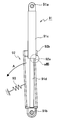
- FIG. 1 is a side view showing the configuration of the cover opening / closing support mechanism of the first exemplary embodiment, and FIGS. 2A and 2B are top views thereof.
- the cover opening / closing support mechanism of the first exemplary embodiment includes a gas spring 1 and a gas spring stopper 2.
- the gas spring 1 consists of a cylinder part 1c and a rod part 1d.
- the gas spring 1 further includes a gas spring fulcrum 1a at the upper end of the cylinder portion 1c on the opening / closing cover 101 side, and a gas spring fulcrum 1b at the lower end of the rod portion 1d on the cabinet fixing side of the automatic transaction apparatus 100.
- the gas spring stopper 2 includes a stopper portion 2a, a limiter portion 2b, and a release handle portion 2c.
- the stopper portion 2a locks the gas spring 1.
- the limiter 2b prevents the stopper 2a from coming into contact with the rod 1d of the gas spring 1 and damaging the rod 1d.
- the release handle 2c is for releasing the stopper.
- the center of gravity of the gas spring stopper 2 is located on the release handle portion 2c side as shown in FIG. The position is 2 g. As a result, a moment in the direction of arrow A is generated by the weight of the release handle 2c.
- the positional relationship between the stopper portion 2a and the limiter portion 2b is shown as a state when the opening / closing cover of FIG. 2B is opened, and before the stopper portion 2a contacts the rod portion 1d, the limiter portion 2b is connected to the gas spring 1. This is a positional relationship in contact with the cylinder portion 1c.
- the cover opening / closing support mechanism of the first exemplary embodiment operates as follows. This operation will be described in detail below with reference to the configuration diagram of the cover opening / closing support mechanism of FIGS. 1, 2A and 2B, and the external perspective view and the operation explanatory view of the automatic transaction apparatus of FIGS. 5A and 5B.
- the rear door 102 When checking the internal unit of the automatic transaction apparatus 100, the rear door 102 is unlocked and opened, and the screw is removed from the rear. Next, when the opening / closing cover 101 provided with the operation panel is opened as shown in FIG. 5B, the gas spring 1 is gradually extended. At this time, the stopper portion 2a for stopping the gas spring 1 from dropping is in a state parallel to the gas spring 1 as shown in the top view of FIG. 2A.
- the cover opening / closing support mechanism of the first exemplary embodiment does not rotate the gas spring stopper 2 strongly by the urging portion as in the prior art, so that the limiter portion 2b becomes the thin lid portion 1c of the gas spring 1.
- the stopper portion 2a does not come into contact with the rod portion 1d of the gas spring 1 as shown in FIG. 2B.
- the opening / closing cover 101 does not hang down from its open position due to its own weight or is not closed carelessly.
- the release handle 2c is pushed in the direction opposite to the arrow A direction to release the contact between the stopper 2a and the cylinder 1c of the gas spring 1, and the locked state Is released.
- the opening / closing cover 101 is closed, screwed from the rear, the rear door 102 is locked, and the maintenance work is completed.
- the release handle is provided on the substantially opposite side of the stopper of the gas spring stopper, and the center of gravity of the gas spring stopper is The spring stopper is rotated from the center axis to the opposite side of the stopper by its own weight. Therefore, the cover opening / closing support mechanism of the automatic transaction apparatus according to the first exemplary embodiment can reliably lock the gas spring without providing an urging member such as a spring, and the stopper portion is attached to the rod portion of the gas spring. It does not touch and damage the rod part.
- FIGS. 3A and 3B show the top surface of the cover opening and closing support mechanism of the second exemplary embodiment.
- a space 12f into which the rod portion 1d of the gas spring 1 can enter is provided and opposed to each other with the space 12f interposed therebetween.
- Two portions 12a are provided on both sides. Since other configurations are the same as those of the first exemplary embodiment, detailed description thereof is omitted for the sake of brevity.
- the side view of the cover opening / closing support mechanism of the second exemplary embodiment is substantially the same as FIG.
- the cover opening / closing support mechanism of the second exemplary embodiment operates as follows. This operation will be described in detail using the cover opening / closing support mechanism shown in FIGS. 3A and 3B.
- the rear door 102 is unlocked and opened as in the first exemplary embodiment.
- the gas spring 1 is gradually extended.
- the stopper portion 12a for stopping the fall of the gas spring 1 is in a state parallel to the gas spring 1 as shown in FIG. 3A.
- the cover opening / closing support mechanism of the second exemplary embodiment does not rotate the gas spring stopper 2 more strongly by the urging portion as in the prior art, and further, by providing a space 12f, the stopper portion 12a can be provided.
- the accuracy of the positional relationship between the limiter portion 2b and the stopper portion 12a is lowered by increasing the width. Therefore, in the cover opening / closing support mechanism of the second exemplary embodiment, since the limiter portion 2b always comes into contact with the cylinder portion 1c of the gas spring 1 first, the stopper portion 12a is in contact with the rod portion 1d of the gas spring 1. Can be eliminated.
- the opening / closing cover 101 does not hang down from its open position due to its own weight or is not closed carelessly.
- the release handle 2c is pushed in the direction opposite to the direction of the arrow C to release the contact between the stopper 12a and the cylinder 1c of the gas spring 1.
- the opening / closing cover 101 is closed, screwed from the rear, the rear door 102 is locked, and the maintenance work is completed.
- the space for allowing the rod portion of the gas spring to enter can be provided, and the stopper portion can be provided so as to face the space and contact the cylinder portion.
- the range of the stopper is widened. Therefore, in addition to the effects of the first exemplary embodiment, the cover opening / closing support mechanism of the second exemplary embodiment can more reliably lock the gas spring and there is variation in the positional accuracy of the stopper portion and the limiter portion. However, the contact between the stopper portion and the rod portion can be reliably prevented.
- cover opening / closing support mechanism for opening and closing the cover opening / closing support mechanism in the vertical direction
- cover opening / closing support mechanism of the present invention can also be applied to a cover that opens and closes in a diagonally up / down direction or a substantially horizontal direction.
- the present invention can be widely used in an automatic transaction apparatus such as an automatic teller machine equipped with a cover opening / closing support mechanism using a gas spring.
Landscapes
- Engineering & Computer Science (AREA)
- Mechanical Engineering (AREA)
- General Engineering & Computer Science (AREA)
- Fluid-Damping Devices (AREA)
- Closing And Opening Devices For Wings, And Checks For Wings (AREA)
- Air-Flow Control Members (AREA)
Abstract
Description
図1は、第1の例示的実施形態のカバー開閉支持機構の構成を示す側面図あり、図2A、及び図2Bは、その上面図である。図1に示したように、第1の例示的実施形態のカバー開閉支持機構は、ガススプリング1と、ガススプリングストッパ2とからなる。 [First exemplary embodiment]
FIG. 1 is a side view showing the configuration of the cover opening / closing support mechanism of the first exemplary embodiment, and FIGS. 2A and 2B are top views thereof. As shown in FIG. 1, the cover opening / closing support mechanism of the first exemplary embodiment includes a gas spring 1 and a
図3A及び図3Bは、第2の例示的実施形態のカバー開閉支持機構の上面部を示す。図3A及び図3Bに示されるように、第2の例示的実施形態のカバー開閉支持機構では、ガススプリング1のロッド部1dが入り込める空間12fを設け、当該空間12fを挟んで対向して、ストッパ部12aを両側2ヶ所設けている。その他の構成は第1の例示的実施形態の構成と同様であるので、簡略化のために、その詳細な説明は省略する。なお、第2の例示的実施形態のカバー開閉支持機構の側面図は、図1とほぼ同様となっている。 [Second exemplary embodiment]
3A and 3B show the top surface of the cover opening and closing support mechanism of the second exemplary embodiment. As shown in FIGS. 3A and 3B, in the cover opening / closing support mechanism of the second exemplary embodiment, a
以上の実施例の説明では、カバー開閉支持機構を上下方向に開閉する開閉カバーに備えた例を説明した。しかしながら、本発明のカバー開閉支持機構は、斜め上下方向や略水平方向に開閉するカバーにも適用できる。 [Other exemplary embodiments]
In the description of the above embodiment, the example in which the cover opening / closing support mechanism for opening and closing the cover opening / closing support mechanism in the vertical direction has been described. However, the cover opening / closing support mechanism of the present invention can also be applied to a cover that opens and closes in a diagonally up / down direction or a substantially horizontal direction.
Claims (4)
- 両端部に支点を備えシリンダ部とロッド部を具備したガススプリングと、
前記一方端部の支点により回動自在に設け、前記ガススプリングが伸びきったときに前記シリンダ部と当接してガススプリングをロックさせるストッパ部と、
当該ストッパ部が前記ロッド部と当接する前に前記シリンダ部と当接するリミッタ部を具備したガススプリングストッパと、
を備えた、カバー開閉支持機構であって、
前記ガススプリングストッパのストッパ部と略反対側に前記ロックを解除する解除取っ手部を設け、前記解除取手部の重さにより前記ガススプリングストッパが前記ストッパ部と略反対側に回動するようにした、
カバー開閉支持機構。 A gas spring having a fulcrum at both ends and a cylinder part and a rod part;
A stopper part that is provided so as to be rotatable by a fulcrum of the one end part, and locks the gas spring by contacting the cylinder part when the gas spring is fully extended;
A gas spring stopper provided with a limiter part that comes into contact with the cylinder part before the stopper part comes into contact with the rod part;
A cover opening / closing support mechanism comprising:
A release handle for releasing the lock is provided on the substantially opposite side of the stopper of the gas spring stopper, and the gas spring stopper is rotated substantially on the opposite side of the stopper by the weight of the release handle. ,
Cover opening / closing support mechanism. - 前記ストッパ部は、前記ガススプリングのロッド部が入り込める空間を備え、当該空間を挟んで対向して設けられた、請求項1に記載のカバー開閉支持機構。 The cover opening / closing support mechanism according to claim 1, wherein the stopper portion includes a space in which the rod portion of the gas spring can enter, and is provided to face the space.
- 請求項1のカバー開閉支持機構を備えた、自動取引装置。 An automatic transaction apparatus comprising the cover opening / closing support mechanism according to claim 1.
- 請求項2記載のカバー開閉支持機構を備えた、自動取引装置。 An automatic transaction apparatus comprising the cover opening / closing support mechanism according to claim 2.
Priority Applications (2)
| Application Number | Priority Date | Filing Date | Title |
|---|---|---|---|
| US13/510,002 US9109387B2 (en) | 2010-03-02 | 2010-12-01 | Cover opening-and-closing support mechanism employing gas spring, and automatic transaction apparatus |
| CN201080051241.9A CN102667226B (en) | 2010-03-02 | 2010-12-01 | Cover opening and closing support mechanism using gas spring, and automatic transaction device |
Applications Claiming Priority (2)
| Application Number | Priority Date | Filing Date | Title |
|---|---|---|---|
| JP2010044927A JP5473676B2 (en) | 2010-03-02 | 2010-03-02 | Cover opening / closing support mechanism using gas spring and automatic transaction apparatus |
| JP2010-044927 | 2010-03-02 |
Publications (1)
| Publication Number | Publication Date |
|---|---|
| WO2011108163A1 true WO2011108163A1 (en) | 2011-09-09 |
Family
ID=44541836
Family Applications (1)
| Application Number | Title | Priority Date | Filing Date |
|---|---|---|---|
| PCT/JP2010/071498 WO2011108163A1 (en) | 2010-03-02 | 2010-12-01 | Cover opening and closing support mechanism using gas spring, and automatic transaction device |
Country Status (4)
| Country | Link |
|---|---|
| US (1) | US9109387B2 (en) |
| JP (1) | JP5473676B2 (en) |
| CN (2) | CN103867631B (en) |
| WO (1) | WO2011108163A1 (en) |
Cited By (1)
| Publication number | Priority date | Publication date | Assignee | Title |
|---|---|---|---|---|
| US8724711B2 (en) | 2011-07-12 | 2014-05-13 | Intel Corporation | Luma-based chroma intra prediction |
Families Citing this family (7)
| Publication number | Priority date | Publication date | Assignee | Title |
|---|---|---|---|---|
| KR101253450B1 (en) | 2011-11-25 | 2013-04-11 | 주식회사 엘지씨엔에스 | Financial device |
| US9387985B2 (en) * | 2013-12-24 | 2016-07-12 | Oshkosh Corporation | Tailgate assembly for a refuse vehicle |
| US9746014B1 (en) * | 2014-01-15 | 2017-08-29 | Nicholas C. Cassaro | Strut retention device |
| CN106567633A (en) * | 2016-11-16 | 2017-04-19 | 广西柳工机械股份有限公司 | Loader cab door locking device easy to unlock |
| US20220042359A1 (en) * | 2020-08-04 | 2022-02-10 | Timothy B. Bothwell | Lift support bracing device and method |
| US11551503B1 (en) * | 2022-03-28 | 2023-01-10 | Laith Ismail Alniami | Sanitizing system |
| WO2023192690A1 (en) * | 2022-03-28 | 2023-10-05 | Alniami Laith | Sanitizing system |
Citations (7)
| Publication number | Priority date | Publication date | Assignee | Title |
|---|---|---|---|---|
| JPS5614636A (en) * | 1979-07-11 | 1981-02-12 | Kayaba Ind Co Ltd | Holding mechanism of stay damper at its extreme extension |
| JPS60192137A (en) * | 1984-02-21 | 1985-09-30 | フイヒテル・アンド・ザツクス・インダストリーズ・インコーポレイテツド | Gas spring unit |
| JPH04109239U (en) * | 1991-03-05 | 1992-09-22 | 甲府日本電気株式会社 | gas spring |
| JPH08153265A (en) * | 1994-11-29 | 1996-06-11 | Fujitsu Ltd | Device with door drop preventing mechanism |
| JPH10115340A (en) * | 1996-10-11 | 1998-05-06 | Kayaba Ind Co Ltd | Stay damper |
| JPH11201210A (en) * | 1998-01-12 | 1999-07-27 | Tokiko Fukushima Kk | Cylinder device |
| JP2000303736A (en) * | 1999-04-16 | 2000-10-31 | White House:Kk | Trap door fixing member, and trap door fixing device |
Family Cites Families (11)
| Publication number | Priority date | Publication date | Assignee | Title |
|---|---|---|---|---|
| US4811983A (en) * | 1986-11-17 | 1989-03-14 | Clark Equipment Company | Gas spring with latching stop mechanism for use on skid-steer loaders |
| US5740744A (en) | 1994-11-29 | 1998-04-21 | Fujitsu Limited | Through-wall type automatic customer service apparatus |
| US5575513A (en) * | 1995-04-03 | 1996-11-19 | Tuttle; Willis A. | Automobile hood strut lock |
| US5659925A (en) * | 1996-02-21 | 1997-08-26 | Patterson; E. Ennalls | Door closer holding mechanism |
| DE19714646A1 (en) * | 1997-04-09 | 1998-10-15 | Suspa Compart Ag | Adjustable gas spring |
| JP2001159442A (en) * | 1999-12-01 | 2001-06-12 | Unisia Jecs Corp | Stay damper |
| AT502943B1 (en) * | 2005-04-01 | 2011-07-15 | Blum Gmbh Julius | DAMPING DEVICE FOR MOVABLE FURNITURE PARTS |
| DE202005021617U1 (en) * | 2005-04-05 | 2008-11-27 | Stabilus Gmbh | Bending resistant piston-cylinder unit |
| US7730579B2 (en) * | 2006-09-19 | 2010-06-08 | Thomas Edward Coe | Door closure apparatus |
| JP2008190691A (en) * | 2007-02-07 | 2008-08-21 | Hitachi Ltd | Hydraulic shock absorber |
| US7731165B2 (en) * | 2007-08-17 | 2010-06-08 | Paccar Inc | Hood support |
-
2010
- 2010-03-02 JP JP2010044927A patent/JP5473676B2/en active Active
- 2010-12-01 WO PCT/JP2010/071498 patent/WO2011108163A1/en active Application Filing
- 2010-12-01 US US13/510,002 patent/US9109387B2/en active Active
- 2010-12-01 CN CN201410090282.9A patent/CN103867631B/en active Active
- 2010-12-01 CN CN201080051241.9A patent/CN102667226B/en not_active Ceased
Patent Citations (7)
| Publication number | Priority date | Publication date | Assignee | Title |
|---|---|---|---|---|
| JPS5614636A (en) * | 1979-07-11 | 1981-02-12 | Kayaba Ind Co Ltd | Holding mechanism of stay damper at its extreme extension |
| JPS60192137A (en) * | 1984-02-21 | 1985-09-30 | フイヒテル・アンド・ザツクス・インダストリーズ・インコーポレイテツド | Gas spring unit |
| JPH04109239U (en) * | 1991-03-05 | 1992-09-22 | 甲府日本電気株式会社 | gas spring |
| JPH08153265A (en) * | 1994-11-29 | 1996-06-11 | Fujitsu Ltd | Device with door drop preventing mechanism |
| JPH10115340A (en) * | 1996-10-11 | 1998-05-06 | Kayaba Ind Co Ltd | Stay damper |
| JPH11201210A (en) * | 1998-01-12 | 1999-07-27 | Tokiko Fukushima Kk | Cylinder device |
| JP2000303736A (en) * | 1999-04-16 | 2000-10-31 | White House:Kk | Trap door fixing member, and trap door fixing device |
Cited By (1)
| Publication number | Priority date | Publication date | Assignee | Title |
|---|---|---|---|---|
| US8724711B2 (en) | 2011-07-12 | 2014-05-13 | Intel Corporation | Luma-based chroma intra prediction |
Also Published As
| Publication number | Publication date |
|---|---|
| JP2011179602A (en) | 2011-09-15 |
| JP5473676B2 (en) | 2014-04-16 |
| CN102667226B (en) | 2015-07-01 |
| CN102667226A (en) | 2012-09-12 |
| CN103867631A (en) | 2014-06-18 |
| US20120228812A1 (en) | 2012-09-13 |
| CN103867631B (en) | 2017-01-04 |
| US9109387B2 (en) | 2015-08-18 |
Similar Documents
| Publication | Publication Date | Title |
|---|---|---|
| WO2011108163A1 (en) | Cover opening and closing support mechanism using gas spring, and automatic transaction device | |
| KR200409014Y1 (en) | An auto locking device for windows | |
| CA2901255A1 (en) | Reinforced strike assembly | |
| KR200465812Y1 (en) | Automatic locking device for sliding windows | |
| FR2916007A1 (en) | PERFECT HANDLE SQUARE FOR ANY OPENING ELEMENT | |
| KR200439303Y1 (en) | Window handle lock | |
| US10323438B2 (en) | Two-point lock | |
| JP5700082B2 (en) | Cover opening / closing support structure using gas spring and automatic transaction apparatus | |
| KR101003821B1 (en) | One touch - type open device for counter | |
| JP7206208B2 (en) | collet latch | |
| JP2012237323A (en) | Hinge mechanism | |
| JP5069420B2 (en) | Door device | |
| JP5644583B2 (en) | Lock mechanism and automatic transaction apparatus equipped with the same | |
| JP5838623B2 (en) | Locking device | |
| JP2019173474A (en) | Door including openable/closable opening for decompression and panel opening/closing operation device | |
| JP2008144432A (en) | Panel door stopper structure | |
| KR100722532B1 (en) | Lock device of noise-proof door | |
| US20040040821A1 (en) | Drop safe having a gas spring control system | |
| JP2022080914A (en) | Fire door locking device | |
| EP3489442B1 (en) | Window or door including a locking system | |
| JP2011153458A (en) | Finger pinching prevention device of door | |
| JP6605235B2 (en) | Money storage device | |
| KR20230149443A (en) | Panel door lock that can be used in a narrow space | |
| JP4746408B2 (en) | Locking device and folding door using the same | |
| EP3653817A1 (en) | Locking device for compressed closing of a door |
Legal Events
| Date | Code | Title | Description |
|---|---|---|---|
| WWE | Wipo information: entry into national phase |
Ref document number: 201080051241.9 Country of ref document: CN |
|
| 121 | Ep: the epo has been informed by wipo that ep was designated in this application |
Ref document number: 10847059 Country of ref document: EP Kind code of ref document: A1 |
|
| WWE | Wipo information: entry into national phase |
Ref document number: 13510002 Country of ref document: US |
|
| NENP | Non-entry into the national phase |
Ref country code: DE |
|
| 122 | Ep: pct application non-entry in european phase |
Ref document number: 10847059 Country of ref document: EP Kind code of ref document: A1 |