WO2011105231A1 - フィルタ係数符号化装置、フィルタ係数復号装置、動画像符号化装置、動画像復号装置、および、データ構造 - Google Patents
フィルタ係数符号化装置、フィルタ係数復号装置、動画像符号化装置、動画像復号装置、および、データ構造 Download PDFInfo
- Publication number
- WO2011105231A1 WO2011105231A1 PCT/JP2011/052923 JP2011052923W WO2011105231A1 WO 2011105231 A1 WO2011105231 A1 WO 2011105231A1 JP 2011052923 W JP2011052923 W JP 2011052923W WO 2011105231 A1 WO2011105231 A1 WO 2011105231A1
- Authority
- WO
- WIPO (PCT)
- Prior art keywords
- filter
- filter coefficient
- coefficient
- prediction
- value
- Prior art date
- Legal status (The legal status is an assumption and is not a legal conclusion. Google has not performed a legal analysis and makes no representation as to the accuracy of the status listed.)
- Ceased
Links
Images







Classifications
-
- H—ELECTRICITY
- H04—ELECTRIC COMMUNICATION TECHNIQUE
- H04N—PICTORIAL COMMUNICATION, e.g. TELEVISION
- H04N19/00—Methods or arrangements for coding, decoding, compressing or decompressing digital video signals
- H04N19/10—Methods or arrangements for coding, decoding, compressing or decompressing digital video signals using adaptive coding
- H04N19/134—Methods or arrangements for coding, decoding, compressing or decompressing digital video signals using adaptive coding characterised by the element, parameter or criterion affecting or controlling the adaptive coding
- H04N19/136—Incoming video signal characteristics or properties
- H04N19/14—Coding unit complexity, e.g. amount of activity or edge presence estimation
-
- H—ELECTRICITY
- H04—ELECTRIC COMMUNICATION TECHNIQUE
- H04N—PICTORIAL COMMUNICATION, e.g. TELEVISION
- H04N19/00—Methods or arrangements for coding, decoding, compressing or decompressing digital video signals
- H04N19/10—Methods or arrangements for coding, decoding, compressing or decompressing digital video signals using adaptive coding
- H04N19/102—Methods or arrangements for coding, decoding, compressing or decompressing digital video signals using adaptive coding characterised by the element, parameter or selection affected or controlled by the adaptive coding
- H04N19/117—Filters, e.g. for pre-processing or post-processing
-
- H—ELECTRICITY
- H04—ELECTRIC COMMUNICATION TECHNIQUE
- H04N—PICTORIAL COMMUNICATION, e.g. TELEVISION
- H04N19/00—Methods or arrangements for coding, decoding, compressing or decompressing digital video signals
- H04N19/10—Methods or arrangements for coding, decoding, compressing or decompressing digital video signals using adaptive coding
- H04N19/169—Methods or arrangements for coding, decoding, compressing or decompressing digital video signals using adaptive coding characterised by the coding unit, i.e. the structural portion or semantic portion of the video signal being the object or the subject of the adaptive coding
- H04N19/17—Methods or arrangements for coding, decoding, compressing or decompressing digital video signals using adaptive coding characterised by the coding unit, i.e. the structural portion or semantic portion of the video signal being the object or the subject of the adaptive coding the unit being an image region, e.g. an object
- H04N19/176—Methods or arrangements for coding, decoding, compressing or decompressing digital video signals using adaptive coding characterised by the coding unit, i.e. the structural portion or semantic portion of the video signal being the object or the subject of the adaptive coding the unit being an image region, e.g. an object the region being a block, e.g. a macroblock
-
- H—ELECTRICITY
- H04—ELECTRIC COMMUNICATION TECHNIQUE
- H04N—PICTORIAL COMMUNICATION, e.g. TELEVISION
- H04N19/00—Methods or arrangements for coding, decoding, compressing or decompressing digital video signals
- H04N19/60—Methods or arrangements for coding, decoding, compressing or decompressing digital video signals using transform coding
- H04N19/61—Methods or arrangements for coding, decoding, compressing or decompressing digital video signals using transform coding in combination with predictive coding
Definitions
- the present invention relates to a moving image encoding apparatus that encodes a moving image and generates encoded data.
- the present invention also relates to a moving picture decoding apparatus that decodes encoded data generated using such a moving picture encoding apparatus.
- the present invention also relates to a filter coefficient encoding apparatus that encodes a filter coefficient and a filter coefficient decoding apparatus that decodes the encoded filter coefficient.
- the present invention also relates to a data structure of encoded data generated by such a filter coefficient encoding device and referred to by such a filter coefficient decoding device.
- a moving image encoding device In order to efficiently transmit or record moving images, a moving image encoding device is used.
- a specific moving picture encoding method for example, H.264 is used.
- an image (picture) constituting a moving image is obtained by dividing a slice obtained by dividing an image, a macroblock obtained by dividing the slice, and a macroblock.
- a slice obtained by dividing an image
- a macroblock obtained by dividing the slice
- a macroblock obtained by dividing the slice
- a macroblock obtained by dividing the slice
- a macroblock is managed by a hierarchical structure composed of sub-blocks, and are usually encoded for each macroblock.
- AVC employs a configuration in which a deblocking filter that acts on a (local) decoded image is provided and a predicted image is generated with reference to the (local) decoded image with reduced block noise.
- the KTA software employs a configuration in which an ALF (Adaptive Loop Filter) is provided after the deblocking filter and a predicted image is generated with reference to the (local) decoded image after application of ALF (Non-patent Document 1). reference).
- the filter coefficient of ALF is adaptively determined so that the error between the decoded image to which ALF is applied and the original image is minimized for each frame or slice on the decoded image.
- the KTA software adopts a configuration that predictively encodes ALF filter coefficients. That is, the difference between the filter coefficient group used for filtering of the encoding / decoding target frame and the prediction filter coefficient group predicted from the filter coefficient group used for filtering of the encoded / decoded frame is encoded.
- a configuration provided to the image decoding apparatus is employed.
- KTA a filter coefficient group used for filtering of encoded / decoded frames is used as it is as a prediction filter coefficient group.
- the filter coefficient group used for filtering of the encoded / decoded frame is the prediction filter coefficient group
- the encoding efficiency does not increase as expected even if predictive encoding is performed, or On the contrary, there is a problem that encoding efficiency is lowered when predictive encoding is performed.
- the present invention has been made in view of the above-described problems, and an object of the present invention is to improve encoding efficiency compared to a conventional configuration in which a filter coefficient group used for filtering of encoded / decoded frames is a prediction filter coefficient group. It is to implement
- the filter coefficient of the peripheral part (filter coefficient multiplied by the pixel value of the peripheral part of the input image) is a frame compared with the filter coefficient of central part (the filter coefficient multiplied by the pixel value of the central part of the input image).
- the correlation was small. Even if predictive encoding is performed, the encoding efficiency does not increase as expected, or the predictive encoding is rather deteriorated. This is also considered to be because predictive coding was performed in the same manner as the filter coefficient at the center of the high correlation between frames.
- the present invention has been made based on this finding.
- the filter coefficient encoding apparatus encodes a difference between a filter coefficient of a target filter acting on a target image and a predicted value of the filter coefficient.
- a prediction value generating means for generating the predicted value by multiplying each filter coefficient of the reference filter acting on the reference image by a weighting coefficient.
- the weighting factor to be multiplied is configured to be closer to 0 than the weighting factor to be multiplied by the filter coefficient at the center.
- the predicted value of the filter coefficient h of the target filter is generated by multiplying the filter coefficient h ′ of the reference filter by the weight coefficient a, and the difference h ⁇ between the filter coefficient h of the target filter and the predicted value ah ′.
- ah ′ is encoded.
- the weighting coefficient a (peripheral part) multiplied by the peripheral coefficient h ′ having a low inter-frame correlation is closer to 0 than the weighting coefficient a (center part) multiplying the peripheral coefficient h ′ having a high inter-frame correlation. I am doing so. For this reason, it is possible to effectively avoid a situation in which the coding efficiency of predictive coding decreases due to
- Another filter coefficient encoding apparatus is a filter coefficient encoding apparatus that encodes a residual of a filter coefficient of a target filter acting on a target image with a predicted value for the filter coefficient.
- 1 is a first predicted value generation means for generating a first predicted value by multiplying each filter coefficient of the reference filter acting on the filter coefficient of the peripheral part, and the weighting coefficient to be multiplied by the filter coefficient of the peripheral part is the filter of the central part
- a first prediction value generating means configured to be smaller than a weighting coefficient to be multiplied by the coefficient; a second prediction value generating means for setting each filter coefficient of the reference filter to a second prediction value; and the weight
- the serial second predicted value is characterized by comprising a prediction value setting means for setting to the predicted value.
- the filter coefficient itself of the reference filter can be used as the predicted value, so that the amount of calculation required to decode the filter coefficient residual is reduced. There is an effect that can be.
- Another filter coefficient encoding apparatus is a filter coefficient encoding apparatus that encodes a residual of a filter coefficient of a target filter acting on a target image with a predicted value for the filter coefficient.
- 1 is a first predicted value generation means for generating a first predicted value by multiplying each filter coefficient of the reference filter acting on the filter coefficient of the peripheral part, and the weighting coefficient to be multiplied by the filter coefficient of the peripheral part is the filter of the central part
- a first prediction value generation unit configured to be smaller than a weighting factor to be multiplied by the coefficient
- a second prediction value generation unit that sets each filter coefficient of the reference filter to a second prediction value
- the first Prediction value setting means for setting one of the predicted values or the second predicted value having a smaller residual with the filter coefficient as the predicted value. It is characterized.
- the residual of the filter coefficient generated by using the first predicted value or the second predicted value having a smaller residual with the filter coefficient as the predicted value is encoded. Therefore, there is an effect that the code amount of the filter coefficient residual can be further reduced.
- the moving picture coding apparatus includes the filter coefficient coding apparatus, and performs filtering using the filter coefficient of the target filter on a locally decoded image.
- the above moving picture coding apparatus has the same effects as the filter coefficient coding apparatus.
- the filter coefficient decoding apparatus restores the filter coefficient of the target filter acting on the target image by adding a prediction value to the filter coefficient residual obtained by decoding the encoded data.
- the coefficient decoding apparatus includes a predicted value generating unit that generates the predicted value by multiplying each filter coefficient of the reference filter that acts on the reference image by a weighting coefficient, and the predicted value generating unit includes a filter coefficient in a peripheral portion.
- the weighting factor to be multiplied by is configured to be closer to 0 than the weighting factor to be multiplied by the filter coefficient at the center.
- the filter coefficient encoding device having a configuration corresponding to the above configuration generates a prediction value of the filter coefficient h of the target filter by multiplying the filter coefficient h ′ of the reference filter by the weight coefficient a, and the filter coefficient of the target filter
- the difference h ⁇ ah ′ between h and the predicted value ah ′ can be encoded, and the weight coefficient a (peripheral part) multiplied by the peripheral coefficient h ′ with low inter-frame correlation is represented as the peripheral part with high inter-frame correlation. It is possible to make it closer to 0 than the weighting coefficient a (center part) multiplied by the coefficient h ′. For this reason, it is possible to effectively avoid a situation in which the coding efficiency of predictive coding decreases due to
- the filter coefficient decoding apparatus having the above-described configuration can decode the encoded data with a small code amount generated as described above.
- Another filter coefficient decoding apparatus adds a predicted value to a filter coefficient residual obtained by decoding encoded data, with a filter coefficient of the target filter acting on the target image.
- a first prediction value generation means for generating a first prediction value by multiplying each filter coefficient of a reference filter acting on a reference image by a weighting coefficient, the filter coefficient of a peripheral portion
- a first prediction value generating means configured to make the weighting coefficient to be multiplied by a weighting coefficient to be multiplied by the filter coefficient in the central portion, and a second prediction value for setting each filter coefficient of the reference filter to a second prediction value.
- the first predicted value is set as the predicted value, and the weighted coefficient If the value is above a predetermined value or more, and the second predicted value and characterized by comprising a prediction value setting means for setting to the predicted value.
- the filter coefficient encoding device having a configuration corresponding to the above configuration, when the value of the weighting factor is smaller than a predetermined value, the weighting factor is calculated as the predicted value. If the weight coefficient value is equal to or greater than a predetermined value, the filter coefficient of the reference filter itself can be used as the predicted value, so that the filter coefficient residual is decoded. It is possible to reduce the amount of calculation required to do.
- the filter coefficient decoding apparatus having the above configuration has an effect of being able to decode encoded data with a small code amount generated as described above.
- Another filter coefficient decoding apparatus adds a predicted value to a filter coefficient residual obtained by decoding encoded data, with a filter coefficient of the target filter acting on the target image.
- a first prediction value generation means for generating a first prediction value by multiplying each filter coefficient of a reference filter acting on a reference image by a weighting coefficient, the filter coefficient of a peripheral portion
- a first prediction value generating means configured to make the weighting coefficient to be multiplied by a weighting coefficient to be multiplied by the filter coefficient in the central portion, and a second prediction value for setting each filter coefficient of the reference filter to a second prediction value.
- the two predicted value generation means and the first predicted value or the second predicted value the one having a smaller residual with the filter coefficient is the predicted value. It is characterized by comprising a prediction value setting means for setting.
- the first predicted value or the second predicted value that has a smaller residual with the filter coefficient is the predicted value. Since the residual of the filter coefficient generated as can be encoded, the code amount of the residual of the filter coefficient can be further reduced.
- the filter coefficient decoding apparatus having the above configuration has an effect of being able to decode encoded data with a small code amount generated as described above.
- the moving picture decoding apparatus includes the filter coefficient decoding apparatus, and performs filtering using the filter coefficient of the target filter on the local decoded image.
- the above moving picture decoding apparatus has the same effects as the filter coefficient decoding apparatus.
- the data structure of the encoded data according to the present invention is encoded data data obtained by encoding a residual of a filter coefficient of a target filter acting on a target image with a predicted value for the filter coefficient.
- the structure includes weight coefficient information that specifies weight coefficients to be multiplied by each filter coefficient of the reference filter that acts on the reference image, and multiplies the peripheral filter coefficients. It is characterized in that the weighting factor is smaller than the weighting factor by which the filter coefficient at the center is multiplied.
- the filter coefficient in the peripheral part tends to have a smaller correlation between frames than the filter coefficient in the central part.
- the code amount of the filter coefficient residual can be reduced by making the weight coefficient multiplied by the filter coefficient in the peripheral part smaller than the weight coefficient multiplied by the filter coefficient in the central part.
- the encoded data having the above configuration is encoded data with a small code amount including such a weight coefficient.
- the filter coefficient decoding apparatus that decodes the encoded data having the above configuration can decode the encoded data with a small code amount of the filter coefficient residual by referring to the weight coefficient information.
- the filter coefficient encoding apparatus is a filter coefficient encoding apparatus that encodes a residual between a filter coefficient of a target filter acting on a target image and a prediction value for the filter coefficient.
- a prediction value generating unit configured to generate the prediction value by multiplying each filter coefficient of the reference filter acting on the image by a weighting coefficient, and the prediction value generating unit includes a weighting coefficient to be multiplied by a filter coefficient in a peripheral portion; It is characterized by being configured so as to be smaller than the weighting coefficient multiplied by the filter coefficient at the center.
- the filter coefficient encoding apparatus configured as described above, the filter coefficient having higher encoding efficiency than the conventional configuration in which the filter coefficient group used for filtering of the encoded / decoded frame is the prediction filter coefficient group.
- An encoding device can be realized.
- Embodiment 1 (Moving picture decoding apparatus 1)
- the moving picture decoding apparatus 1 includes H.264 as a part thereof. H.264 / MPEG-4 AVC, and a decoding device including technology adopted in KTA software.
- FIG. 1 is a block diagram showing a configuration of the moving picture decoding apparatus 1.
- the moving picture decoding apparatus 1 includes a variable length code decoding unit 13, a motion vector restoration unit 14, a buffer memory 15, an inter prediction image generation unit 16, an intra prediction image generation unit 17, and a prediction method determination unit 18. , An inverse quantization / inverse transform unit 19, an adder 20, a deblocking filter 50, and an adaptive filter 100.
- the video decoding device 1 generates and outputs a decoded image # 2 by decoding the encoded data # 1.
- the generation of decoded image # 2 by the moving image decoding apparatus 1 is performed in units of macroblocks or subblocks constituting a frame.
- variable length code decoding unit 13 performs variable length decoding on the encoded data # 1, and performs differential motion vector # 13a, side information # 13b, quantized prediction residual data # 13c, filter coefficient residual # 13d, and filter parameters. Information # 13e is output.
- the side information # 13b includes a prediction mode, a motion vector, a reference image index, a quantization parameter, and the like.
- the filter parameter information # 13e includes a parameter indicating the number of reference pixels for filtering (the number of taps) and information related to a parameter for specifying on / off of filtering.
- the filter parameter information # 13e may include a weighting coefficient used for prediction of the filter coefficient, as will be described later.
- the motion vector restoration unit 14 decodes the motion vector # 14 for the target sub-block from the difference motion vector # 13a and the motion vector # 15a that has already been decoded and stored in the buffer memory 15.
- the buffer memory 15 stores output image data # 100 output from the adaptive filter 100, motion vector # 14, and side information # 13b.
- the inter prediction image generation unit 16 is decoded by the motion vector restoration unit 14 and based on the motion vector # 15c that has passed through the buffer memory 15 and the reference image # 15d stored in the buffer memory 15, the inter prediction image # 16. Is generated.
- the generation of the inter prediction image # 16 is performed in units of macroblocks or subblocks, for example.
- the motion vector # 15c may be the same motion vector as the motion vector # 14.
- the reference image # 15d corresponds to output image data # 100 output from an application filter 100 described later.
- the intra-predicted image generation unit 17 generates an intra-predicted image # 17 from the local decoded image # 15b stored in the buffer memory 15. More specifically, the intra predicted image generation unit 17 generates an image on the prediction target macroblock of the intra predicted image # 17 using the local decoded image # 15b in the same frame as the prediction target macroblock.
- the prediction method determination unit 18 selects one of the intra prediction image # 17 and the inter prediction image # 16 based on the prediction mode information included in the side information # 13b, and outputs the selected prediction image # 18. To do.
- Quantization prediction residual data # 13c is supplied to the inverse quantization / inverse transform unit 19 in units of sub-blocks.
- the inverse quantization / inverse transform unit 19 transforms the quantized prediction residual data # 13c into a frequency component by performing inverse quantization, and further performs inverse DCT (Discrete Cosine Transform) transform on the frequency component. As a result, a prediction residual # 19 is generated and output.
- inverse DCT Discrete Cosine Transform
- the adder 20 generates a decoded image # 2 by adding the prediction residual # 19 and the prediction image # 18, and outputs the decoded image # 2.
- the output decoded image # 2 is also supplied to the deblocking filter 50.
- the deblocking filter 50 performs deblocking processing for reducing block distortion at the block boundary or macroblock boundary on the decoded image # 2.
- the image data subjected to the deblocking process is output as a deblocked image # 50.
- the adaptive filter 100 calculates a filter coefficient based on the filter coefficient residual # 13d decoded from the encoded data # 1, and performs filtering using the filter coefficient on the deblocked image # 50, thereby outputting an output image.
- Data # 100 is generated.
- the output image data # 100 is supplied to the buffer memory 15.
- the filtering process in adaptive filter 100 is performed based on side information # 13b decoded from encoded data # 1 and parameters included in filter parameter information # 13e.
- FIG. 2 is a block diagram showing the configuration of the adaptive filter 100.
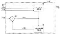
- the adaptive filter 100 includes a filter processing unit 110, a filter coefficient prediction unit 140, and an adder 101.
- the adder 101 generates the filter coefficient # 101 by adding the filter coefficient residual # 13d decoded from the encoded data # 1 and the prediction filter coefficient # 140 output from the filter coefficient prediction unit 140, Output.
- the filter processing unit 110 generates output image data # 100 by filtering the deblocked image # 50 using the filter coefficient # 101 based on the side information # 13b and the filter parameter information # 13e. And output.
- the filter processing unit 110 for example, each pixel value of the deblocked image # 50 and the filter coefficient # of each pixel value included in the filter reference area specified by the filter parameter information # 13e.
- Each pixel value of output image data # 100 is calculated and output by taking a weighted linear sum based on 101 and further adding an offset based on filter coefficient # 101.
- the filter processing unit 110 calculates the pixel value S0 (x ′, y ′) at the coordinates (x ′, y ′) of the output image data # 100 by a weighted linear sum represented by Expression (1). To do.
- SI (x, y) represents the pixel value at the coordinates (x, y) of the deblocked image # 50, and h (i, j) is multiplied by the pixel value SI (x + i, y + j). It represents the filter coefficient.
- O represents an offset value.
- the filter coefficient h (i, j) corresponds to the filter coefficient # 101.
- R represents a filter reference area that is a set of relative coordinates to be subjected to the weighted linear sum. As described above, the filter reference region R is determined based on, for example, the filter parameter information # 13e. Also, the coordinates (x ′, y ′) and the coordinates (x, y) may be the same coordinates or different coordinates.
- Output image data # 100 composed of the pixel value S0 (x ′, y ′) calculated using the above equation (1) is supplied to the buffer memory 15.
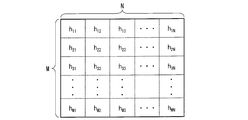
- the filtering process in the filter processing unit 110 is generally performed when the filter reference region R is M ⁇ N taps, and the filter coefficient matrix H is an M ⁇ N matrix having filter coefficients h (i, j) as components.
- hij corresponds to the filter coefficient h (i, j) (the same applies hereinafter).
- FIG. 3 is a diagram showing each pixel included in the filter reference region R and a filter coefficient h (i, j) corresponding to each pixel when the filter reference region R is M ⁇ N taps. . As shown in FIG. 3, a filter coefficient h (i, j) is assigned to each pixel in the M ⁇ N tap filter reference region R.
- the filter coefficient prediction unit 140 calculates the prediction filter coefficient # 140 based on the filter coefficient already decoded in the decoded frame or the filter coefficient already decoded in the frame being decoded among the filter coefficients # 101. .
- the prediction filter coefficient # 140 is output to the adder 101.
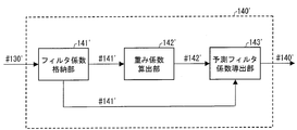
- FIG. 4 is a block diagram showing a configuration of the filter coefficient prediction unit 140.
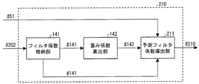
- the filter coefficient prediction unit 140 includes a filter coefficient storage unit 141, a weight coefficient calculation unit 142, and a prediction filter coefficient derivation unit 143.
- the filter coefficient storage unit 141 stores the filter coefficient # 101 output from the adder 101. Further, the filter coefficient storage unit 141 is supplied with the filter coefficient # 141, which is a decoded filter coefficient, to the weighting coefficient calculation unit 142.
- filter coefficients # 141 are filter coefficients # 141a
- filter coefficients already decoded in the frame being decoded are filter coefficients # This is expressed as 141b.
- the filter coefficient matrix H ′ having the filter coefficient # 141 as a component can be expressed by the following equation (3).
- the filter coefficient h ′ (i, j) corresponds to the filter coefficient # 141.
- the weight coefficient calculation unit 142 calculates a weight coefficient a (i, j) to be multiplied by each component h ′ (i, j) of the filter coefficient matrix H ′. More specifically, the weighting factor calculation unit 142 divides the filter reference region R into a plurality of subregions, and calculates a weighting factor a (i, j) for each subregion. The calculated weighting coefficient # 142 is output to the prediction filter coefficient deriving unit 143.
- the weighting coefficient matrix A having the weighting coefficient a (i, j) in each component can be expressed by the following equation (4) when the filter reference region R is M ⁇ N taps.
- the prediction filter coefficient deriving unit 143 includes a filter coefficient h ′ (i, j) already used in the filtering process for the decoded frame among the filter coefficients stored in the filter coefficient storage unit 141, and a weight coefficient calculation unit. Based on the weighting coefficient a (i, j) calculated by 142, the prediction filter coefficient p (i, j) is derived.
- the prediction filter coefficient matrix P having the prediction filter coefficient p (i, j) as a component can be expressed by the following equation (5), for example.
- the prediction filter coefficient deriving unit 143 calculates the prediction filter coefficient p (i, j), and the product of the weight coefficient a (i, j) and the filter coefficient h ′ (i, j). Derived by taking
- the prediction filter coefficient corresponding to the center pixel of the filter reference region R is the filter coefficient # 141b already decoded for the pixels other than the center of the filter reference region R. It is good also as a structure derived
- the prediction filter coefficient deriving unit 143 derives the prediction filter coefficient p_center for the center pixel of the filter reference region R among the prediction filter coefficients p (i, j) using the following equation (6). It is good.
- the sum regarding i and j is the sum for the region R ′ excluding the central pixel in the filter reference region R.
- the prediction accuracy of the prediction filter coefficient is increased by using the tendency that the sum of the filter coefficients h (i, j) in the filter reference region R is close to 1. It can be improved effectively.
- a value corresponding to the quantized coefficients may be used instead of taking a difference from 1. For example, since the filter coefficient quantized with 1/256 as a step has been multiplied by 256, the difference from 256 may be taken.
- the prediction filter coefficient p_center for the center pixel is derived by taking the difference from the value corresponding to the quantization step, instead of taking the difference from 1. What is necessary is just to be the structure to do.
- the prediction filter coefficient p_center for the center pixel can be derived. With such a configuration, the code amount of the filter coefficient residual # 13d included in the encoded data # 1 can be reduced.
- the filter coefficient residual # included in the encoded data # 1 is generated by generating the prediction filter coefficient using the same expression as Expression (6).
- the code amount of 13d can be reduced.
- the moving picture decoding apparatus 1 can decode the encoded data # 1 with a small code amount of the filter coefficient residual # 13d by adopting the above configuration.
- the prediction filter coefficient p (i, j) derived by the prediction filter coefficient deriving unit 143 is supplied to the adder 101 as the prediction filter coefficient # 140.
- the variable length decoding unit 13, the adder 101, and the filter coefficient prediction unit 140 are based on the filter coefficient residual # 13d included in the encoded data # 1.
- a filter coefficient decoding device that decodes the filter coefficient # 101 includes such a filter coefficient decoding device, and is a video decoding device that performs filtering using the filter coefficient # 101 on the deblocked image # 50. It can also be expressed.
- the filter coefficient prediction unit 140 performs any one of the following calculation processes (specific example 1-1) to (specific example 1-5) according to the configuration of the encoded data # 1.
- the calculation process in this example can be suitably applied, for example, when decoding encoded data # 1 configured as described later (Configuration Example 1-1).
- the weight coefficient calculation unit 142 first divides the filter reference region R into a plurality of groups (sub-regions) from the center of the filter reference region R toward the periphery.
- FIG. 5 is a diagram illustrating an example of an arrangement of each group constituting the filter reference region R divided by the weight coefficient calculation unit 142 when the filter reference region R is 9 ⁇ 9 taps.
- the weighting coefficient calculation unit 142 moves the filter reference region R to group 5, group 4, group 3, group 2, and group 1 from the center of the filter reference region R to the periphery. To divide.
- the group 5 includes a pixel at the center of the filter reference region R (hereinafter referred to as a pixel Pc).
- Group 4 is composed of pixels inscribed in the outer edge of the 3 ⁇ 3 tap region centered on pixel Pc
- Group 3 is a pixel inscribed in the outer edge of the 5 ⁇ 5 tap region centered on pixel Pc.
- Group 2 is composed of pixels inscribed in the outer edge of the 7 ⁇ 7 tap area centered on the pixel Pc
- Group 1 is located on the outer edge of the 9 ⁇ 9 tap area centered on the pixel Pc. It consists of pixels in contact.
- the weighting factor calculation unit 142 sets the weighting factor a (i, j) for each group to the value of the weighting factor included in the filter parameter information # 13e.
- the weighting factor a_gr1 for group 1 is 1/4
- the weighting factor a_gr2 for group 2 is 1/2
- the weighting factor a_gr3 for group 3 is 5 /. 8.
- the weight coefficient for group 1 is set to 1/4
- the weight coefficient for group 2 is set to 1/2
- the weight coefficient for group 3 is set to 5 / 8
- the weighting factor for group 4 is set to 3/4
- the weighting factor for group 5 is set to 1.
- the weighting factor calculation unit 142 outputs the weighting factor for each group set in this way as the weighting factor # 142 to the prediction filter factor deriving unit 143, and the prediction filter factor deriving unit 143 outputs the weighting factor # 142.
- predictive filter coefficient # 140 is derived. As described above, when each weighting factor is a multiple of 1/8, the weighting factor calculation unit 142 multiplies each group by 2, 4, 5, 6, and 8 and adds 4 for rounding. However, the weight coefficient # 142 may be calculated using integer arithmetic that shifts right by 3 bits.
- the value of the weighting factor included in the filter parameter information # 13e is not limited to the above example, but in the moving picture encoding device that generates the encoded data # 1, the code of the filter coefficient residual # 13d It is preferably a value calculated so as to reduce the amount.
- the prediction filter coefficient # 140 can be derived based on the filter coefficient residual # 13d with a small code amount in this way.
- the prediction filter coefficient deriving unit 143 may be configured to derive the prediction filter coefficient for the center pixel of the filter reference region R using Expression (6).
- the prediction filter coefficient # 140 can be derived based on the encoded data # 1 having a smaller code amount by using the equation (6).
- the moving picture decoding apparatus 1 uses the tendency that the sum of the filter coefficients h (i, j) in the filter reference region R is close to 1 as described above by using Equation (6). Since the prediction accuracy of the filter coefficient can be effectively improved, it is possible to decode the encoded data # 1 with a small code amount of the filter coefficient residual # 13d.
- the weighting factor calculation unit 142 sets the weighting factor a (i, j) for each group to the value of the weighting factor included in the filter parameter information # 13e. It is not limited to.
- the weight coefficient calculation unit 142 may be configured to set the weight coefficient a (i, j) for each group to the value of the weight coefficient recorded in advance in the memory.
- the prediction filter coefficient # 140 can be derived even when the filter parameter information # 13e does not include the value of the weighting coefficient.
- the weight coefficient value recorded in the memory in advance is preferably the same value as the weight coefficient value used in the moving picture encoding apparatus that generates the encoded data # 1.
- the filter reference region R is 9 ⁇ 9 taps.
- the present invention is not limited to this, and in general, the filter reference region R is It can be applied to the case of M ⁇ N taps.
- the method of dividing the filter reference region R by the weight coefficient calculation unit 142 is not limited to the above example, and an optimal dividing method may be adopted according to the characteristics of the filter coefficient. For example, it is also preferable to divide the weight coefficient for each filter coefficient.
- the filter coefficient prediction unit 140 may divide the filter reference region R into a plurality of sub-regions and derive the prediction filter coefficient # 140 using the weighting factor set for each sub-region. Therefore, the moving image decoding apparatus 1 can generate the decoded image # 2 based on the encoded data # 1 with a small code amount of the filter coefficient residual # 13d.
- the calculation process in this example can be suitably applied, for example, when decoding encoded data # 1 configured as described later (Configuration Example 1-2).
- the weight coefficient calculation unit 142 first divides the filter reference region R into a plurality of groups from the center of the filter reference region R toward the peripheral part, as in (Specific example 1-1).
- the weighting factor calculation unit 142 first calculates the weighting factor a_grG ′ (s) for the region on the decoded frame and the region of the group G using the already decoded filter coefficients.
- the index s in a_grG ′ (s) indicates that the frame is s frames before counting from the prediction target frame.
- the frame before s frames counted from the prediction target frame is referred to as a frame s.
- the weight coefficient calculation unit 142 uses the weight coefficient a_grG ′ (s) for the frame s and the filter referred to for calculating the predicted value of the filter coefficient h (i, j) (s) for the frame s.
- the coefficient h (i, j) (s_prev) and the filter coefficient h (i, j) (s) for the frame s the following equation (7) is used for calculation.
- the sum regarding i and j is the sum for the reference region G corresponding to the group G in the filter reference region R.
- the weighting factor calculation unit 142 calculates the weighting factor a_grG using the representative value of the calculated weighting factor a_grG ′ (s).
- the representative value for example, a median value of the weighting coefficients a_grG ′ (s) calculated for a plurality of frames can be used.
- the weighting factor calculation unit 142 calculates the weighting factor a_grG by the following equation (8).
- a_grG median (a_grG ′ (1), a_grG ′ (2),..., a_grG ′ (F))
- median represents taking the median of the values in parentheses.
- the weighting factor calculation unit 142 is a weighting factor calculated for each frame from one frame before to F frames before counting from the prediction target frame, and the weighting factor a_grG ′ (1) ⁇
- the median value of a_grG ′ (F) is set to the weight coefficient a_grG.
- F a predetermined value may be used, or for example, a different value may be used depending on the position of the filter reference region R in the frame.
- the weighting coefficient used for the prediction of the filter coefficient h (i, j) (s) for the frame s may be used as it is.
- the weighting factor calculation unit 142 outputs the weighting factor a_grG for each group set in this way as the weighting factor # 142 to the prediction filter factor deriving unit 143.
- the prediction filter factor deriving unit 143 outputs the weighting factor # 143. 142 is used to derive prediction filter coefficient # 140.
- the weight coefficient for each group constituting the filter reference region R has a correlation between frames. That is, the weighting coefficient already calculated for each region on the decoded frame tends to be an appropriate value for deriving the prediction filter coefficient for the prediction target frame. Therefore, in the moving picture encoding apparatus that generates the encoded data # 1, the filter coefficient residual # included in the encoded data # 1 is generated by generating a prediction filter coefficient using an expression similar to the expression (8). The code amount of 13d can be reduced. In addition, the filter coefficient prediction unit 140 in the moving image decoding apparatus 1 performs the operation of this example, thereby calculating the prediction filter coefficient # 140 based on the filter coefficient residual # 13d generated in this way with a small code amount. Can be derived.
- the prediction filter coefficient deriving unit 143 may be configured to derive the prediction filter coefficient for the center pixel of the filter reference region R using Expression (6).
- the weighting factor calculation unit 142 includes a memory that stores a weighting factor that has already been calculated for each region on a decoded frame. It becomes.
- the calculation processing in this example can be suitably applied to, for example, decoding encoded data # 1 configured as described later (Configuration Example 1-3).
- the weighting factor calculation unit 142 calculates the weighting factor for each group constituting the filter reference region R by using the average value as the representative value in the above-described (specific example 1-2).
- the weighting factor calculation unit 142 calculates the weighting factor a_grG by the following equation (9) instead of the equation (8).
- Other operations of the weight coefficient calculating unit 142 are the same as those described in the specific example 1-2.
- the index s in a_grG ′ (s) indicates the frame before s frames, counted from the prediction target frame, as in (Specific Example 1-2).
- the weighting factor calculation unit 142 is a weighting factor calculated for each frame from one frame before to F frames before counting from the prediction target frame, and the weighting factor a_grG ′ (1) ⁇
- the average value of a_grG ′ (F) is set to the weight coefficient a_grG.
- the weight coefficient for each group constituting the filter reference region R has a correlation between frames. That is, the weighting coefficient already calculated for each region on the decoded frame tends to be an appropriate value for deriving the prediction filter coefficient for the prediction target frame. Therefore, in the moving picture encoding apparatus that generates the encoded data # 1, the filter coefficient residual # included in the encoded data # 1 is generated by generating a prediction filter coefficient using an expression similar to the expression (9). The code amount of 13d can be reduced. In addition, the filter coefficient prediction unit 140 in the moving image decoding apparatus 1 performs the operation of this example, thereby calculating the prediction filter coefficient # 140 based on the filter coefficient residual # 13d generated in this way with a small code amount. Can be derived.
- the weighting factor calculation unit 142 includes a memory that stores a weighting factor that has already been calculated for each region on a decoded frame. It becomes.
- the calculation process in this example can be suitably applied, for example, when decoding encoded data # 1 configured as described later (Configuration Example 1-4).
- the weight coefficient calculation unit 142 first divides the filter reference region R into a plurality of groups from the center of the filter reference region R toward the peripheral part, as in (Specific example 1-1).
- the weighting factor calculation unit 142 calculates the weighting factor a (i, j) by the least square method.
- the weighting factor calculation unit 142 calculates the weighting factor a (i, j) so as to minimize the square error E1 represented by the following equation (10).
- the variable t represents the frame number associated with each frame. That is, the filter coefficient h (i, j) (t) represents a filter coefficient used for filtering a frame whose frame number is t. O represents an offset.
- h (i, j) (t_prev) is a decoded filter coefficient, which is a filter coefficient referred to for calculation of a prediction filter coefficient corresponding to the filter coefficient h (i, j) (t). Represents.
- the weight coefficient a (i, j) may be calculated so as to minimize the square error E1 obtained by taking the sum of -1.
- the weight coefficient calculation unit 142 minimizes the square error E1 obtained by summing the frames from the smallest frame interval to the prediction target frame to the current frame among the decoded intra-frame encoded frames (intra frames).
- the weighting factor calculation unit 142 averages the weighting factor a (i, j) calculated using the least square method for each group constituting the filter reference region, thereby obtaining the weighting factor a_grG for each group. Calculated and output to the prediction filter coefficient deriving unit 143 as the weight coefficient # 142.
- the prediction filter coefficient deriving unit 143 derives the prediction filter coefficient # 140 using the weighting coefficient # 142.
- the prediction filter coefficient is calculated based on the least square method using the same equation as the equation (10), so that it is included in the encoded data # 1.
- the code amount of the filter coefficient residual # 13d can be reduced.
- the filter coefficient prediction unit 140 in the moving image decoding apparatus 1 performs the operation of this example, thereby calculating the prediction filter coefficient # 140 based on the filter coefficient residual # 13d generated in this way with a small code amount. Can be derived.
- the weighting coefficient calculation unit 142 takes the median value of the weighting coefficient a (i, j) calculated by using the least square method for each group constituting the filter reference region, so that the weighting coefficient a_grG for each group is obtained. It is good also as a structure which calculates.
- the weight coefficient calculation unit 142 may be configured to apply the least square method directly to each group without taking the average value or the median value.
- the weighting factor calculation unit 142 may be configured to calculate the weighting factor a_grG of the group G so as to minimize the square error E2 represented by the following equation (11).
- the sum regarding i and j represents the sum for the reference region G corresponding to the group G in the filter reference region R.
- O represents an offset.
- the prediction filter coefficient deriving unit 143 may be configured to derive the prediction filter coefficient for the center pixel of the filter reference region R using Expression (6).
- the calculation process in this example can be suitably applied to, for example, decoding encoded data # 1 configured as described later (Configuration Example 1-5).
- the weight coefficient calculation unit 142 first sets the filter reference region R to the first sub region that is the peripheral portion of the filter reference region R and the second sub region that is a region other than the first sub region. Divide into areas.
- the peripheral part of the filter reference region R is a region in the filter reference region R, which is in contact with the outer edge of the filter reference region R or in the vicinity of the outer edge of the filter reference region R (hereinafter referred to as “the reference region”). The same).
- the weighting factor calculation unit 142 sets the value of the weighting factor for the first subregion to 0, and sets the value of the weighting factor for the second subregion to 1. Further, the value of the weighting factor for the second sub-region is not limited to 1, and a weighting factor calculated by any of the methods described in specific examples 1-1 to 1-4 may be used.
- the weighting coefficient matrix A1 composed of the weighting coefficients a (i, j) calculated by the weighting coefficient calculating unit 142 in this way is shown in the following formula (12).
- a component having a value of 0 in the weighting coefficient matrix A1 represents a weighting factor for the first sub-region
- a component having a value of 1 represents a weighting factor for the second sub-region.
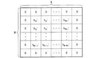
- each component of the prediction filter coefficient matrix P calculated by the prediction filter coefficient deriving unit 143 becomes 0 for each pixel corresponding to the first group,
- the filter coefficient h ′ (i, j) is a value as it is.
- FIG. 6 is a diagram illustrating each component of the prediction filter coefficient P corresponding to each pixel in the filter reference region R of M ⁇ N taps.
- the value of the prediction filter coefficient corresponding to each pixel in the peripheral part of the filter reference region R (that is, the prediction filter coefficient corresponding to the first group) is 0, and the peripheral part of the filter reference region R
- the values of the prediction filter coefficients corresponding to the other pixels are the values of the filter coefficients h ′ (i, j) as they are.
- the filter coefficient corresponding to each pixel in the periphery of the filter reference region R tends to be a value close to zero.
- the filter coefficient prediction unit 140 in the moving image decoding apparatus 1 performs the operation of this example, thereby calculating the prediction filter coefficient # 140 based on the filter coefficient residual # 13d generated in this way with a small code amount. Can be derived.
- prediction filter coefficient deriving unit 143 in this example may be configured to derive the prediction filter coefficient for the center pixel of the filter reference region R using Expression (6).
- the moving picture encoding apparatus 2 includes H.264 as a part thereof. H.264 / MPEG-4 AVC, and a decoding device including technology adopted in KTA software.
- FIG. 7 is a block diagram showing a configuration of the moving picture encoding apparatus 2.
- the moving image encoding device 2 includes a transform / quantization unit 21, a variable length encoding unit 22, an inverse quantization / inverse transform unit 23, a buffer memory 24, an intra predicted image generation unit 25, an inter prediction image generation unit 25, and an inter prediction image generation unit 25.
- a prediction image generation unit 26, a prediction scheme control unit 28, a motion vector redundancy reduction unit 29, an adder 31, a subtractor 32, a deblocking filter 50, and an adaptive filter 100 ′ are provided.
- the input image # 10 divided into macro blocks is input to the moving image encoding device 2.
- the moving image encoding device 2 performs an encoding process on the input image # 10 and outputs encoded data # 1.
- the transform / quantization unit 21 converts the difference image # 32 between the input image # 10 divided into macroblocks and a prediction image # 28a output from the prediction scheme control unit 28, which will be described later, into frequency components by DCT conversion. After conversion, the frequency component is quantized to generate quantized prediction residual data # 21.
- the quantization is an operation for associating the frequency component with an integer value.
- the DCT transform and quantization are performed in units of blocks obtained by dividing a macroblock.
- a macro block to be processed is referred to as a “target macro block”
- a block to be processed is referred to as a “target block”.
- the inverse quantization / inverse transform unit 23 decodes the quantized prediction residual data # 21 and generates a prediction residual # 23. Specifically, the inverse quantization / inverse transform unit 23 performs inverse quantization of the quantized prediction residual data # 21, that is, associates integer values constituting the quantized prediction residual data # 21 with frequency components. Then, inverse DCT transformation of the frequency component, that is, inverse transformation to the pixel component of the target macroblock based on the frequency component is performed to generate prediction residual # 23.
- the adder 31 adds the prediction residual # 23 and the prediction image # 28a to generate a decoded image # 31.
- the generated decoded image # 31 is supplied to the deblocking filter 50.
- the deblocking filter 50 performs a deblocking process on the block boundary or the macroblock boundary in the decoded image # 31.
- the image data subjected to the deblocking process is output as a deblocked image # 50.
- the deblocking filter 50 has the same configuration as the deblocking filter 50 included in the video decoding device 1.
- the adaptive filter 100 ′ performs filtering on the deblocked image # 50 and outputs output image data # 100 ′ to the buffer memory 24.
- the adaptive filter 100 ′ also outputs a filter coefficient residual # 102 that is a residual between the filter coefficient used for filtering and the predicted filter coefficient to the variable length coding unit 22.
- the adaptive filter 100 ′ is a variable-length encoding unit for filtering parameter information, which is information related to a parameter indicating an area to be filtered, a parameter indicating the number of taps for filtering, and a parameter for specifying on / off of filtering. 22 is output. Since the configuration of the adaptive filter 100 ′ will be described later, the description thereof is omitted here.
- the intra-predicted image generation unit 25 extracts the local decoded image # 24a (the already decoded region in the same frame as the target macroblock) from the output image data # 100 ′ stored in the buffer memory 24, and based on the local decoded image # 24a Intra-frame prediction is performed to generate intra-predicted image # 25.
- the inter prediction image generation unit 26 calculates and assigns a motion vector # 27 to the target block on the input image # 10 by using the reference image # 24b in which the entire frame has already been decoded and stored in the buffer memory 24. .
- the calculated motion vector # 27 is output to the inter prediction image generation unit 26 and the motion vector redundancy reduction unit 29 and is stored in the buffer memory 24.
- the inter predicted image generation unit 26 performs motion compensation on the reference image # 24b based on the motion vector # 27 for each block, and generates an inter predicted image # 26.
- the prediction method control unit 28 compares the intra prediction image # 25, the inter prediction image # 26, and the input image # 10 in units of macro blocks, and the intra prediction image # 25 or the inter prediction image # 26. Any one of them is selected and output as a predicted image # 28a. In addition, the prediction method control unit 28 outputs a prediction mode # 28b that is information indicating which one of the intra prediction image # 25 or the inter prediction image # 26 is selected. The predicted image # 28a is input to the subtracter 32.
- the prediction mode # 28b is stored in the buffer memory 24 and input to the variable length encoding unit 22.
- the motion vector redundancy reduction unit 29 assigns the motion vector # 27 to the target block in the inter predicted image generation unit 26, and then assigns the motion vector # 27c to the other block and stored in the buffer memory 24. Based on this, a prediction vector is calculated. In addition, the motion vector redundancy reduction unit 29 takes the difference between the prediction vector and the motion vector # 27, and generates a difference motion vector # 29. The generated difference motion vector # 29 is output to the variable length coding unit 22.
- variable length encoding unit 22 performs variable length encoding on the quantized prediction residual data # 21, the differential motion vector # 29, the prediction mode # 28b, the filter coefficient residual # 102, and the filter parameter information, Coded data # 1 is generated.
- the subtractor 32 takes the difference between the input image # 10 and the predicted image # 28a for the target macroblock, and outputs a difference image # 32.
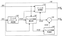
- FIG. 8 is a block diagram showing a configuration of the adaptive filter 100 ′.
- the adaptive filter 100 ′ includes a filter processing unit 110 ′, a filter parameter determination unit 120 ′, a filter coefficient derivation unit 130 ′, a filter coefficient prediction unit 140 ′, and a subtractor 102.
- the filter parameter determination unit 120 ′ based on the side information of the input image # 10, sets a parameter indicating the number of reference pixels for filtering (number of taps), a parameter group that specifies filtering on / off, and the like (hereinafter referred to as filter parameters).
- the filter parameter information # 120 ′ which is information including the filter parameter group, is output.
- the side information of the input image # 10 includes a prediction mode, a motion vector, a reference image index indicating a reference frame, a quantization parameter, and the like.
- the filter parameter group determination method does not limit the present invention.
- the filter parameter determination unit 120 ′ determines the block size of the blocks constituting the input image # 10 or the input image # 10.
- a configuration may be adopted in which the filter parameter group is determined according to the number of hierarchies when hierarchically divided by a quad-tree.
- the subtractor 102 generates and outputs a filter coefficient residual # 102 by taking the difference between the filter coefficient # 130 'and the prediction filter coefficient # 140'.
- the filter processing unit 110 ′ generates and outputs output image data # 100 ′ by filtering the deblocked image # 50 using the filter coefficient # 130 ′.
- the filtering process in the filter processing unit 110 ′ is almost the same as the filtering process in the filter processing unit 110 in the moving image decoding apparatus 1 described above.
- the filter processing unit 110 represents the pixel value S0 (x ′, y ′) at the coordinates (x ′, y ′) of the output image data # 100 ′ by the above equation (1), and the filter coefficient # It is calculated by taking a weighted linear sum with 130 ′ and adding an offset based on filter coefficient # 101.
- the filter coefficient h (i, j) in Expression (1) corresponds to the filter coefficient # 130'.
- the filter coefficient deriving unit 130 ′ derives the filter coefficient # 130 ′ using the input image # 10 and the deblocked image # 50 based on the filter parameter information # 120 ′ output from the filter parameter determining unit 120 ′. .
- the derived filter coefficient # 130 ′ is output to the filter coefficient prediction unit 140 ′, the subtractor 102, and the filter processing unit 110 ′.
- the filter coefficient deriving unit 130 ′ determines the value of the filter coefficient h (i, j) by, for example, the following expression (13), each pixel value of the input image # 10 and each pixel of the output image data # 100 ′. Derived so as to minimize the square error E3 with the value.
- S (x, y) represents the pixel value at the coordinates (x, y) of the input image # 10
- SI (x, y) represents the coordinates (x, y) of the deblocked image # 50.
- O represents an offset.
- the filter coefficient h (i, j) derived in this way (1 ⁇ i ⁇ M, 1 ⁇ j ⁇ N) is output as filter coefficient # 130 ′ from the filter coefficient deriving unit 130 ′, and the filter processing unit Used for filtering at 110 '.
- the filter coefficient prediction unit 140 ′ performs substantially the same operation as the filter coefficient prediction unit 140 included in the video decoding device 1. However, in the moving picture coding apparatus 2, the filter coefficient supplied to the filter coefficient prediction unit 140 ′ is the filter coefficient # 130 ′, and the prediction filter coefficient output from the filter coefficient prediction unit 140 ′ is the prediction filter coefficient. # 140 '.
- FIG. 9 is a block diagram showing the configuration of the filter coefficient prediction unit 140 '.
- the filter coefficient prediction unit 140 ' includes a filter coefficient storage unit 141', a weight coefficient calculation unit 142 ', and a prediction filter coefficient derivation unit 143'.
- the filter coefficient storage unit 141 ′ performs substantially the same operation as the filter coefficient storage unit 141 in the video decoding device 1. However, the filter coefficient stored in the filter coefficient storage unit 141 ′ includes the filter coefficient # 141 ′ already used in the filtering process for the encoded frame.
- the filter coefficient matrix that is stored in the filter coefficient storage unit 141 ′ and that is configured by the filter coefficient # 141 ′ that has already been used in the filtering process for the encoded frame is expressed as in Expression (2) already described. be able to.
- the filter coefficient h ′ (i, j) corresponds to the filter coefficient # 141 ′ already used in the filtering process for the encoded frame.
- the weight coefficient calculation unit 142 ′ calculates the weight coefficient a (i, j) by which each component h ′ (i, j) of the filter coefficient matrix H ′ is multiplied. To do. Since a specific example of the calculation processing of the weighting factor a (i, j) by the weighting factor calculating unit 142 ′ will be described later, the description thereof is omitted here.
- the prediction filter coefficient derivation unit 143 ′ Similar to the prediction filter coefficient derivation unit 143 in the video decoding device 1, the prediction filter coefficient derivation unit 143 ′ performs filtering processing on an encoded frame among the filter coefficients stored in the filter coefficient storage unit 141 ′. Based on the already used filter coefficient h ′ (i, j) and the weight coefficient a (i, j) calculated by the weight coefficient calculation unit 142 ′, the prediction filter coefficient p (i, j) is derived. . The derived prediction filter coefficient p (i, j) is output as prediction filter coefficient # 140 '.
- the prediction filter coefficient matrix P having the prediction filter coefficient p (i, j) as a component can be expressed, for example, as already described in Expression (5).
- the prediction filter coefficient deriving unit 143 ′ uses the filter for pixels other than the center of the filter reference region R for prediction filter coefficients corresponding to the center pixel of the filter reference region R among the prediction filter coefficients p (i, j). It is good also as a structure derived
- the prediction filter coefficient deriving unit 143 ′ derives the prediction filter coefficient p_center for the center pixel of the filter reference region R among the filter coefficients h (i, j) using the already-described expression (6). It is good also as a structure.
- the prediction accuracy of the prediction filter coefficient is increased by using the tendency that the sum of the filter coefficients h (i, j) in the filter reference region R is close to 1. It can be improved effectively.
- the sum of filter coefficients in the filter reference region R tends to be close to 1. Therefore, according to the above configuration, the code amount of the filter coefficient residual # 102 can be reduced.
- the variable length coding unit 22, the subtractor 102, and the filter coefficient prediction unit 140 ′ are filter coefficient # 130 supplied from the filter coefficient deriving unit 130 ′.
- a filter coefficient encoding apparatus that encodes a filter coefficient residual # 102 that is a residual between 'and a prediction filter coefficient # 140' predicted based on the filter coefficient # 130 'is configured. it can. Therefore, the moving picture coding apparatus 2 according to the present embodiment can also be expressed as a moving picture coding apparatus including such a filter coefficient coding apparatus.
- the filter coefficient prediction unit 140 'performs an operation corresponding to the calculation process of the prediction filter coefficient # 140 by the filter coefficient prediction unit 140 described in (Specific example 1-1).
- the weight coefficient calculation unit 142 ′ first divides the filter reference region R into a plurality of groups (subregions) from the center of the filter reference region R toward the periphery (see FIG. 5).
- the weighting factor calculation unit 142 sets the weighting factor a (i, j) for each group to a predetermined value.
- a predetermined value for example, a value determined in advance by the method of least squares may be used.
- FIG. 10 shows weighting factors a (i, j) corresponding to groups 1 to 4 constituting the filter reference region R shown in FIG. 5 by using four different sequences and four different quantization parameters. It is a graph which shows the result computed beforehand by applying the least squares method to the frame for 200 frames.
- the square error to be minimized in the least square method the square error E1 represented by the already described formula (10) was taken.
- the optimum weighting coefficient obtained by the least square method has a larger value in a region closer to the center of the filter reference region R. This is because the correlation between the frames of the filter coefficients becomes larger as the region is closer to the center of the filter reference region R.
- the weighting factor calculation unit 142 ′ sets the optimum weighting factor value for each group obtained in advance by the least square method or an approximate value thereof as the weighting factor for each pixel belonging to each group. .
- the weighting factor calculation unit 142 ′ multiplies 2, 4, 5, 6, and 8 for each group to round 4 for rounding.
- the weight coefficient # 142 may be calculated using integer arithmetic that adds 3 and shifts right by 3 bits.
- the weighting coefficient calculation unit 142 ′ outputs the weighting coefficient a_grG for each group set in this way as the weighting coefficient # 142 ′ to the prediction filter coefficient derivation unit 143 ′, and the prediction filter coefficient derivation unit 143 ′
- the prediction filter coefficient # 140 ′ is derived using the weight coefficient # 142 ′.
- the value of the weight coefficient a_gr5 for the group 5 may be determined according to the values of the weight coefficients a_gr1 to a_gr4, or a predetermined value (for example, 1) may be used.
- the prediction filter coefficient deriving unit 143 ′ may be configured to derive the prediction filter coefficient for the central pixel of the filter reference region R among the prediction filter coefficients # 140 ′ using the already-described formula (6). Good.
- the filter coefficient prediction unit 140 ′ divides the filter reference region R into a plurality of sub-regions, and derives a prediction filter coefficient # 140 ′ using the weighting factor set for each sub-region. Therefore, the code amount of the filter coefficient residual # 102 can be reduced as compared with the conventional method in which the filter reference region R is not divided.
- the weighting factor calculation unit 142 ′ stores the value of the weighting factor in a memory, so that the optimum weighting factor can be obtained without performing the weighting factor calculation process using the least square method. Therefore, it is possible to output an optimum weight coefficient while reducing the amount of calculation compared to the case where the least square method is used for each frame.
- the code amount of the filter coefficient residual # 102 can be reduced with a small amount of calculation.
- the weighting factor calculation unit 142 ′ performs grouping from the center of the filter reference region R of M ⁇ N taps toward the peripheral part, and the weighting factor for each group is determined by an optimal method obtained in advance by the least square method. It can be set as a structure which sets to a weighting coefficient or its approximate value.
- the method of dividing the filter reference region R by the weight coefficient calculating unit 142 ′ is not limited to the above example, and an optimal dividing method may be adopted according to the characteristics of the filter coefficient. For example, it is also preferable to divide the weight coefficient for each filter coefficient.
- the filter coefficient prediction unit 140 'performs an operation corresponding to the calculation process of the prediction filter coefficient # 140 by the filter coefficient prediction unit 140 described in (Specific example 1-2).
- the weight coefficient calculation unit 142 ′ first divides the filter reference region R into a plurality of groups from the center of the filter reference region R toward the peripheral part, as in (Specific example 1-1 ′).
- the weighting factor calculation unit 142 ′ first calculates the weighting factor a_grG ′ (s) for the region on the decoded frame and the region of the group G using the already encoded filter coefficients. To do.
- the index s in a_grG ′ (s) indicates that the frame is s frames before counting from the prediction target frame.
- the frame before s frames counted from the prediction target frame is referred to as a frame s.
- the weight coefficient calculation unit 142 ′ is referred to calculate the weight coefficient a_grG ′ (s) for the frame s and the predicted value of the filter coefficient h (i, j) (s) for the frame s. Using the filter coefficient h (i, j) (s_prev) and the filter coefficient h (i, j) (s) for the frame s, the calculation is performed according to the equation (7) already described.
- the weighting factor calculation unit 142 ′ calculates the weighting factor a_grG using the representative value of the calculated weighting factor a_grG ′ (s).
- the representative value for example, the median value of the weighting coefficient a_grG ′ (s) calculated for a plurality of frames can be used.
- the weighting factor calculation unit 142 calculates the weighting factor a_grG by the equation (8) already described.
- the weighting factor calculation unit 142 ′ is a weighting factor calculated for each frame from one frame before to F frames before counting from the prediction target frame, and the weighting factor a_grG ′ (1) for the group G Set the median value of a_grG ′ (F) to the weight coefficient a_grG.
- the specific value of F may be a predetermined value as in (Specific Example 1-2), or determined according to the position of the filter reference region R in the frame, for example. The value to be used may be used.
- the weighting coefficient used for the prediction of the filter coefficient h (i, j) (s) for the frame s may be used as it is.
- the weighting coefficient calculation unit 142 ′ outputs the weighting coefficient a_grG for each group set in this way as the weighting coefficient # 142 ′ to the prediction filter coefficient derivation unit 143 ′, and the prediction filter coefficient derivation unit 143 ′
- the prediction filter coefficient # 140 ′ is derived using the weight coefficient # 142 ′.
- the filter coefficient prediction unit 140 ′ can reduce the code amount of the filter coefficient residual # 102 by performing the operation as in this example.
- prediction filter coefficient deriving unit 143 may be configured to derive the prediction filter coefficient for the center pixel of the filter reference region R using Expression (6).
- the above-described operation by the weighting factor calculation unit 142 ′ is performed, for example, by including a memory in which the weighting factor calculation unit 142 stores a weighting factor that has already been calculated for each region on the decoded frame. It becomes possible.
- the filter coefficient prediction unit 140 'performs an operation corresponding to the calculation process of the prediction filter coefficient # 140 by the filter coefficient prediction unit 140 described in (Specific Example 1-3).
- the weighting factor calculation unit 142 ′ calculates the weighting factor for each group constituting the filter reference region R by using the average value as the representative value in the above-described (specific example 1-2 ′). .
- the weighting factor calculation unit 142 ′ calculates the weighting factor a_grG according to Expression (9).
- the weighting factor calculation unit 142 ′ is a weighting factor calculated for each frame from one frame before to F frames before counting from the prediction target frame, and the weighting factor a_grG ′ (1) for the group G
- the average value of .about.a_grG ′ (F) is set to the weighting coefficient a_grG.
- the filter coefficient prediction unit 140 ′ can reduce the code amount of the filter coefficient residual # 102 by performing the operation as in this example.
- the filter coefficient prediction unit 140 'performs an operation corresponding to the calculation process of the prediction filter coefficient # 140 by the filter coefficient prediction unit 140 described in (Specific Example 1-4).
- the weight coefficient calculation unit 142 ′ first divides the filter reference region R into a plurality of groups from the center of the filter reference region R toward the peripheral part, as in (Specific example 1-1 ′).
- the weighting factor calculation unit 142 calculates the weighting factor a (i, j) by the least square method.
- the weighting factor calculating unit 142 calculates the weighting factor a (i, j) so as to minimize the square error E1 represented by the already described formula (10).
- h (i, j) (t_prev) in the equation (10) is an encoded filter coefficient in this example, and is a prediction filter coefficient corresponding to the filter coefficient h (i, j) (t). It shall represent the filter coefficient referred for calculation.
- the specific calculation processing of the weighting factor a (i, j) by the weighting factor calculation unit 142 'in this example is the same as (Specific example 1-4).
- the weighting coefficient calculation unit 142 ′ calculates the weighting coefficient a_grG for each group by averaging the weighting coefficient a (i, j) calculated using the least square method for each group constituting the filter reference region. It is calculated and output to the prediction filter coefficient deriving unit 143 ′ as the weight coefficient # 142 ′.
- the prediction filter coefficient deriving unit 143 ' uses the weighting coefficient # 142' to derive the prediction filter coefficient # 140 '.
- the weight coefficient calculation unit 142 ′ calculates the weight coefficient for each group using the least square method, so that the code amount of the filter coefficient residual # 102 can be reduced.
- the weighting factor calculation unit 142 ′ calculates the weighting factor a (i, j) calculated using the least squares method for each group constituting the filter reference region. It is good also as a structure which calculates weighting coefficient a_grG with respect to each group by taking a value.
- the weighting factor calculation unit 142 ′ may be configured to calculate the weighting factor a_grG for each group by the least square method using Equation (11), as in (Specific Example 1-4).
- the prediction filter coefficient deriving unit 143 ' may be configured to derive the prediction filter coefficient for the center pixel of the filter reference region R using Expression (6).
- the filter coefficient prediction unit 140 'performs an operation corresponding to the calculation process of the prediction filter coefficient # 140 by the filter coefficient prediction unit 140 described in (Specific example 1-5).
- the weight coefficient calculation unit 142 ′ divides the filter reference region R into a first sub-region that is a peripheral portion of the filter reference region R and a second sub-region that is a region other than the first sub-region.
- the peripheral part of the filter reference region R is a region in the filter reference region R, which is in contact with the outer edge of the filter reference region R or in the vicinity of the outer edge of the filter reference region R (hereinafter referred to as “the reference region”). The same).
- the weighting factor calculation unit 142 sets the value of the weighting factor for the first subregion to 0, and sets the value of the weighting factor for the second subregion to 1.
- the weighting coefficient matrix A1 composed of the weighting coefficients a (i, j) calculated by the weighting coefficient calculating unit 142 in this way can be expressed as in Expression (12).
- a component having a value of 0 in the weighting coefficient matrix A1 represents a weighting factor for the first sub-region
- a component having a value of 1 represents a weighting factor for the second sub-region.
- each component of the prediction filter coefficient matrix P calculated by the prediction filter coefficient deriving unit 143 ′ becomes 0 for each pixel corresponding to the first group.
- the filter coefficient h ′ (i, j) is a value as it is (see FIG. 6).
- the filter coefficient corresponding to each pixel in the periphery of the filter reference region R tends to be a value close to zero.
- the amount of calculation related to calculation of the prediction filter coefficient can be reduced.
- the code amount of the filter coefficient residual # 101 can be reduced.
- the value of the filter coefficient corresponding to the peripheral pixels of the filter reference region R is 0.1.
- the filter coefficient h ′ (i, j) when the value of the filter coefficient corresponding to the peripheral pixel of the filter reference region R is ⁇ 0.1, the filter coefficient h ′ (i, j) If the filter coefficient residual is generated with the prediction filter coefficient as is, the value of the filter coefficient residual corresponding to the above pixel becomes 0.2, but this corresponds to the peripheral pixel of the filter reference region R as in this example.
- a filter coefficient residual is generated by setting the value of the prediction filter coefficient to be 0, the value of the filter coefficient residual corresponding to the pixel is 0.1.
- the code amount of the filter coefficient residual # 102 can be reduced.
- prediction filter coefficient deriving unit 143 in this example may be configured to derive the prediction filter coefficient for the center pixel of the filter reference region R using Expression (6).
- FIG. 11A shows a bit stream #BS for each slice of the encoded data # 1 generated by the video encoding device 2 and referred to by the video decoding device 1.
- the bitstream #BS includes filter parameter information FP, filter coefficient residual information RC, and macroblock information MB1 to MBN.
- the filter coefficient residual information RC is information including the filter coefficient residual # 102 generated in the video encoding device 2.
- Macroblock information MB1 to MBN is information used for decoding macroblocks existing in a slice. N represents the number of macroblocks present in the slice.
- the macroblock information includes a prediction mode, a motion vector, a reference image index, a quantization parameter, quantized prediction residual data, and the like.
- (B) of FIG. 11 shows an example of the configuration of the filter parameter information FP.
- the filter parameter information FP includes a parameter (number of taps) indicating the number of reference pixels for filtering and on / off designation information for designating filtering on / off.
- the filter parameter information FP may be configured to include weight coefficient information indicating the weight coefficient # 142 'calculated in the video encoding device 2.
- the filter coefficient residual includes the filter coefficient residual # 102 generated using the prediction filter coefficient # 140 'calculated by the process described in (Specific example 1-1').
- the weight coefficient information of the filter parameter information FP in the encoded data # 1 may be configured to include the weight coefficient # 142 ′ calculated in (Specific example 1-1 ′). Further, the weight coefficient information may include a parameter indicating the weight coefficient # 142 ′ instead of the weight coefficient # 142 ′ itself. For example, if the weighting factor of each group is a multiple of 1/8, such as 2/8, 4/8, 5/8, 6/8, 8/8, the numerator (2, 4, 5, 6, 8) and denominator (8) as parameters are included in the weight coefficient information. Further, when the weight coefficient # 142 ′ is recorded in advance in the memory included in the video decoding device 1, the weight coefficient information of the filter parameter information FP may not be included.
- the filter target region information may include information indicating how the filter reference region R is divided, for example, information indicating that the filter reference region R is grouped as illustrated in FIG. .
- the filter coefficient residual includes the filter coefficient residual # 102 generated using the prediction filter coefficient # 140 'calculated by the process described in (Specific example 1-2').
- the filter parameter information FP in the encoded data # 1 does not include weighting coefficient information. good.
- the filter target region information may include information indicating how the filter reference region R is divided, for example, information indicating that the filter reference region R is grouped as illustrated in FIG. .
- the filter coefficient residual includes the filter coefficient residual # 102 generated using the prediction filter coefficient # 140 'calculated by the processing described in (Specific Example 1-3').
- the filter parameter information FP in the encoded data # 1 does not include weighting coefficient information. good.
- the filter target region information may include information indicating how the filter reference region R is divided, for example, information indicating that the filter reference region R is grouped as illustrated in FIG. .
- the filter coefficient residual includes the filter coefficient residual # 102 generated using the prediction filter coefficient # 140 'calculated by the process described in (Specific Example 1-4').
- the filter parameter information FP in the encoded data # 1 does not include weighting coefficient information. good.
- the filter target region information may include information indicating how the filter reference region R is divided, for example, information indicating that the filter reference region R is grouped as illustrated in FIG. .
- the filter coefficient residual includes the filter coefficient residual # 102 generated using the prediction filter coefficient # 140 'calculated by the processing described in (Specific example 1-5').
- the filter parameter information FP in the encoded data # 1 does not include weighting coefficient information. good.
- the filter target region information may include information indicating how the filter reference region R is divided, for example, information indicating that the filter reference region R is grouped as illustrated in FIG. .
- FIG. 12 is a block diagram illustrating a configuration of the moving image decoding apparatus 3.
- the same blocks as those shown in FIG. 1 are denoted by the same reference numerals, and the description thereof is omitted.
- the moving image decoding apparatus 3 includes a variable length code decoding unit 51, a motion vector restoration unit 14, a buffer memory 15, an inter prediction image generation unit 16, an intra prediction image generation unit 17, and a prediction method determination unit 18. , An inverse quantization / inverse transform unit 19, an adder 20, a deblocking filter 50, and an adaptive filter 200.
- the video decoding device 3 receives the encoded data # 5 and outputs a decoded image # 6.
- variable-length code decoding unit 51 performs variable-length decoding on the encoded data # 5, performs differential motion vector # 13a, side information # 13b, quantized prediction residual data # 13c, filter coefficient residual # 13d, filter parameter information # 13e and flag # 51 indicating the filter coefficient calculation method are output.
- the adaptive filter 200 calculates a filter coefficient based on the filter coefficient residual # 13d according to the filter coefficient calculation method indicated by the flag # 51 decoded from the encoded data # 5, and applies the filter coefficient to the deblocked image # 50.
- Output image data # 200 is generated by performing filtering using.
- the output image data # 200 is supplied to the buffer memory 15.
- the filtering process in adaptive filter 200 is performed based on side information # 13b decoded from encoded data # 5 and parameters included in filter parameter information # 13e.
- FIG. 13 is a block diagram showing the configuration of the adaptive filter 200.
- the same reference numerals are assigned to the same blocks as those shown in FIG. 2, and the description thereof is omitted.
- the adaptive filter 200 includes a filter processing unit 110, a filter coefficient prediction unit 210, and an adder 202.
- the adder 202 generates the filter coefficient # 202 by adding the filter coefficient residual # 13d decoded from the encoded data # 5 and the prediction filter coefficient # 210 output from the filter coefficient prediction unit 210, Output.
- the filter coefficient prediction unit 210 follows the method indicated by the flag # 51 indicating the filter coefficient calculation method, and based on the filter coefficient already used in the filtering process for the decoded frame of the filter coefficient # 202, the prediction filter coefficient # 210 is calculated. Prediction filter coefficient # 210 is output to adder 202.
- FIG. 14 is a block diagram illustrating a configuration of the filter coefficient prediction unit 210.
- the same blocks as those shown in FIG. 4 are denoted by the same reference numerals, and the description thereof is omitted.
- the filter coefficient prediction unit 210 includes a filter coefficient storage unit 141, a weight coefficient calculation unit 142, and a prediction filter coefficient derivation unit 211.
- the filter coefficient prediction unit 210 outputs a prediction filter coefficient # 210 similar to the prediction filter coefficient # 140 described in (Specific example 1-1) to (Specific example 1-5) according to the flag # 51, or Alternatively, the filter coefficient # 141 already used in the filtering process for the decoded frame is output as the prediction filter coefficient # 210.
- the prediction filter coefficient derivation unit 211 included in the filter coefficient prediction unit 210 is calculated by the decoded filter coefficient # 141 and the weighting coefficient calculation unit 142. Based on the weighting coefficient # 142, each component of the prediction filter coefficient matrix P expressed by Expression (5) is derived and output as the prediction filter coefficient # 210.
- the calculation method of the weighting factor in the weighting factor calculation unit 142 any one of (Specific Example 1-1) to (Specific Example 1-5) described above may be used.
- the prediction filter coefficient deriving unit 211 outputs the decoded filter coefficient # 141 as the prediction filter coefficient # 210.
- the filter coefficient prediction unit 210 outputs the decoded filter coefficient # 141 as the prediction filter coefficient # 210 according to the flag # 51, or individually calculates for each group in the filter reference region R.
- the filter coefficient derived using the weighted coefficient is output as prediction filter coefficient # 210.
- the filter coefficient prediction unit 210 can decode the encoded data # 5 including the filter coefficient residual # 13d with a smaller code amount by performing such an operation.
- the filter coefficient prediction unit 210 outputs the decoded filter coefficient # 141 as the prediction filter coefficient # 210 without referring to the flag # 51, or is calculated individually for each group in the filter reference region R
- the filter coefficient derived using the weighting coefficient may be output as the prediction filter coefficient # 210.
- the weighting factor calculation unit 142 calculates the weighting factor # 142 by the method described in (Specific Example 1-2) of the first embodiment for each group constituting the 9 ⁇ 9 tap filter reference region
- the prediction filter is used in accordance with the same method as that shown in (Specific example 1-2) of the first embodiment using the weight coefficient a_grG.
- the coefficient # 210 may be derived, and if not, the decoded filter coefficient # 141 may be output as the prediction filter coefficient # 210.
- the weight coefficient # 142 calculated by the weight coefficient calculation unit 142 represents the correlation between frames.
- the region to which the smaller weight coefficient # 142 is assigned has a lower correlation between the filter coefficients in that region.
- the moving picture coding apparatus having a configuration corresponding to the above configuration, it is possible to more effectively reduce the code amount of the filter coefficient residual for the region where the correlation between the filter coefficient frames is lower. Moreover, according to said structure, the encoded data produced
- variable-length code decoding unit 51, the adder 202, and the filter coefficient prediction unit 210 are filter coefficient decoding devices that decode the filter coefficient # 202 based on the filter coefficient residual # 13d. It can be understood that it is composed.
- FIG. 15 is a block diagram illustrating a configuration of the moving image encoding device 4.
- the same blocks as those shown in FIG. 7 are denoted by the same reference numerals, and the description thereof is omitted.
- the moving image encoding device 4 includes a transform / quantization unit 21, an inverse quantization / inverse transform unit 23, a buffer memory 24, an intra predicted image generation unit 25, an inter predicted image generation unit 26, and a prediction.
- a system control unit 28, a motion vector redundancy reduction unit 29, an adder 31, a subtractor 32, a deblocking filter 50, a variable length coding unit 41, and an adaptive filter 200 ′ are provided.
- the input image # 4 divided into block images composed of a plurality of adjacent pixels is input to the moving image encoding device 4.
- the moving image encoding device 4 performs an encoding process on the input image # 4 and outputs encoded data # 5.
- variable-length encoding unit 41 applies the quantized prediction residual data # 21, the difference motion vector # 29, the prediction mode # 28b, the flag # 220 indicating the filter coefficient prediction method, and the filter coefficient residual # 102. Variable length encoding is performed to generate encoded data # 5.
- the adaptive filter 200 ′ generates output image data # 200 ′ by filtering the deblocked image # 50 and outputs the output image data # 200 ′ to the buffer memory 24.
- the adaptive filter 200 ′ also outputs a filter coefficient residual # 102 that is a residual between the filter coefficient used for filtering and the predicted filter coefficient to the variable length coding unit 41.
- the adaptive filter 200 ′ also outputs a flag # 220 indicating the filter coefficient prediction method to the variable length coding unit 41.
- FIG. 16A shows a first configuration example of the adaptive filter 200 ′.
- the adaptive filter 200 ′ outputs the prediction filter coefficient selected according to the value of the weighting coefficient calculated by the filter coefficient prediction unit 210 ′.
- the adaptive filter 200 ′ includes a filter processing unit 110 ′, a filter parameter determination unit 120 ′, a filter coefficient derivation unit 130 ′, a filter coefficient prediction unit 210 ′, a subtractor 201a, and A prediction means selection unit 220a is provided.
- the subtractor 201a generates a filter coefficient residual # 102 by taking the difference between the filter coefficient # 130 'and the prediction filter coefficient # 210', and outputs the filter coefficient residual # 102 to the variable length coding unit 41.
- FIG. 17 is a block diagram illustrating a configuration of the filter coefficient prediction unit 210 ′.
- the same blocks as those shown in FIG. 9 are denoted by the same reference numerals, and the description thereof is omitted.
- the filter coefficient prediction unit 210 ′ includes a filter coefficient storage unit 141 ′, a weight coefficient calculation unit 142 ′, and a prediction filter coefficient derivation unit 211 ′.
- weighting coefficient # 142 'calculated by the weighting coefficient calculation unit 142' in the filter coefficient prediction unit 210 ' is also supplied to the prediction means selection unit 220a.
- the prediction filter coefficient deriving unit 211 ′ is configured according to the value of the flag # 220 supplied from the prediction unit selection unit 220a (specific example 1). -1 ′) to (prediction example 1-5 ′) in which the prediction filter coefficient # 210 ′ similar to the prediction filter coefficient # 140 ′ described above is output, or in the filtering process for the encoded frame
- the filter coefficient # 141 ′ already used is output as the prediction filter coefficient # 210 ′.
- the prediction means selection unit 220a outputs the flag # 220 depending on whether the value of the weight coefficient # 142 ′ is equal to or greater than a predetermined value.
- the weighting factor calculating unit 142 ′ calculates the weighting factor # 142 ′ by the method described in the first embodiment (specific example 1-2 ′) for each group constituting the 9 ⁇ 9 tap filter reference region.
- a flag # 220 indicating that a prediction filter coefficient is derived using the weight coefficient a_grG is output.
- the prediction means selection unit 220a uses the filter coefficient # 141 ′ already used in the filtering process for the encoded frame. A flag # 220 indicating output is output.
- any one of groups 1 to 4 may be taken.
- an average value of the weight coefficients a_gr1 to a_gr4 for each group may be used.
- the flag # 220 is output to the variable length coding unit 41 and is referred to by the prediction filter coefficient deriving unit 211.
- the weighting coefficient # 142 'calculated by the weighting coefficient calculation unit 142' represents a correlation between frames.
- the region to which the smaller weight coefficient # 142 'is assigned has a lower correlation between the filter coefficient frames in the region.
- the filter coefficient prediction unit 210 ′ derives the prediction filter coefficient # 210 ′ using the weighting coefficient # 142 ′, so that the filter coefficient residual # 102 for the region where the correlation between the frames of the filter coefficient is lower is obtained. Can be more effectively reduced. For regions where the correlation between the filter coefficient frames is higher, the calculation amount can be reduced by outputting the prediction filter coefficient # 210 'without using the weighting coefficient # 142'.
- the filter coefficient prediction unit 210 can effectively reduce the code amount of the filter coefficient residual # 102 while reducing the calculation amount.
- the weight coefficient calculation unit 142 ′ uses the weight coefficient # 142 by the method described in (Specific example 1-1 ′) to (Specific example 1-5 ′) of the first embodiment. It can be applied to the case where 'is calculated.
- the moving picture decoding apparatus that decodes the encoded data # 5 generated by the present configuration example sets the weight coefficient value calculated by the configuration corresponding to the weight coefficient calculation unit 142 ′ to the predetermined threshold th. By comparing the decoded filter coefficients with the predicted filter coefficients without referring to the flag # 220, or the weight coefficients calculated individually for each group in the filter reference region R. It is also possible to perform decoding processing using the filter coefficient derived by using the prediction filter coefficient.
- the prediction means selection unit 220a may be configured not to supply the flag # 220 to the variable length coding unit 41.
- FIG. 16B shows a second configuration example of the adaptive filter 200 ′.
- the adaptive filter 200 ′ is replaced with the prediction means selection section 220b described in (Configuration example 1 of the adaptive filter 200 ′), instead of the prediction means selection section 220b. It has.
- the prediction filter coefficient deriving unit 211 in this example uses the same prediction filter coefficient as the prediction filter coefficient # 140 ′ described in any one of (Specific example 1-1 ′) to (Specific example 1-5 ′), and performs encoding.
- the filter coefficient # 141 ′ already used in the filtering process for the already-completed frame is output as the prediction filter coefficient # 210 ′.
- the subtractor 201b generates a filter coefficient residual # 201b by taking the difference between the filter coefficient # 130 'and the prediction filter coefficient # 210' and outputs it to the prediction means selection unit 220b.
- the filter coefficient residual # 201b is already used in the filtering process for the filter coefficient residual # RC1 calculated using the prediction filter coefficient derived using the weighting coefficient # 142 ′ and the encoded frame.
- the filter coefficient residual # RC2 calculated using the obtained filter coefficient.
- the prediction means selection unit 220b compares the filter coefficient residual # RC1 with the filter coefficient residual # RC2, and outputs a smaller filter coefficient residual as the filter coefficient residual # 102.
- the input to the predictor selection unit 220b is used as the code amount of the filter coefficient residual, the two are compared, and the filter coefficient residual corresponding to the smaller code amount is set as the filter coefficient residual # 102. It may be configured to output.
- the prediction means selection unit 220b when outputting the filter coefficient residual # RC1, the prediction means selection unit 220b outputs a flag # 220 indicating that the prediction filter coefficient is derived using the weight coefficient # 142 ′, and the filter coefficient residual # RC1.
- a flag # 220 indicating that the prediction filter coefficient is calculated using the filter coefficient already used in the filtering process for the encoded frame is output.
- the adaptive filter 200 ′ can output the filter coefficient residual # 102 with a smaller code amount.
- variable-length encoding unit 41, the subtractor 201a (or subtractor 201b), and the filter coefficient prediction unit 210 ′ are filter coefficient encoding devices that encode the filter coefficient # 130 ′. It can be understood that it is composed.
- the data structure of the encoded data # 5 is almost the same as the data structure of the encoded data # 1 already described with reference to (a) to (b) of FIG. 11, but differs in the following points.
- the filter parameter information FP in the encoded data # 5 has a prediction filter coefficient derived using a weighting coefficient or filtering for an encoded frame A flag indicating whether the calculation has been performed using the filter coefficient already used in the processing is included. Further, the flag is included in the filter parameter information FP in the encoded data # 5.
- the video decoding device 3 that decodes the encoded data # 5 can derive the prediction filter coefficient by using the same method as that used in the video encoding device 4 by referring to the flag. Therefore, the moving picture decoding apparatus 3 that decodes the encoded data # 5 can decode the encoded data # 5 including the filter coefficient residual # 102 with a smaller code amount by referring to the flag.
- the encoded data # 5 includes the weight coefficient information. It can be set as the structure which does not contain.
- the code amount of the encoded data # 5 can be further reduced.
- the filter coefficient residual included in the encoded data # 5 corresponds to the filter coefficient residual derived using the filter coefficient already used in the filtering process for the encoded frame.
- the filter coefficient of the peripheral part (filter coefficient multiplied by the pixel value of the peripheral part of the input image) is a frame compared with the filter coefficient of central part (the filter coefficient multiplied by the pixel value of the central part of the input image).
- the correlation was small. Even if predictive encoding is performed, the encoding efficiency does not increase as expected, or the predictive encoding is rather deteriorated. This is also considered to be because predictive coding was performed in the same manner as the filter coefficient at the center of the high correlation between frames.
- the present invention has been made based on this finding.
- the filter coefficient encoding apparatus encodes a difference between a filter coefficient of a target filter acting on a target image and a predicted value of the filter coefficient.
- a prediction value generating means for generating the predicted value by multiplying each filter coefficient of the reference filter acting on the reference image by a weighting coefficient.
- the weighting factor to be multiplied is configured to be closer to 0 than the weighting factor to be multiplied by the filter coefficient at the center.
- the predicted value of the filter coefficient h of the target filter is generated by multiplying the filter coefficient h ′ of the reference filter by the weight coefficient a, and the difference h ⁇ between the filter coefficient h of the target filter and the predicted value ah ′.
- ah ′ is encoded.
- the weighting coefficient a (peripheral part) multiplied by the peripheral coefficient h ′ having a low inter-frame correlation is closer to 0 than the weighting coefficient a (center part) multiplying the peripheral coefficient h ′ having a high inter-frame correlation. I am doing so. For this reason, it is possible to effectively avoid a situation in which the coding efficiency of predictive coding decreases due to
- the filter coefficient encoding apparatus further includes storage means for storing the weight coefficient, and the predicted value generation means receives a weight coefficient multiplied by the filter coefficient of the target filter in the storage means. It is preferably configured to be the median value of the accumulated weight coefficients.
- the weight coefficient multiplied by each filter coefficient of the reference filter has a correlation between images. That is, the weighting coefficient used for generating the predicted value of the encoded filter coefficient tends to be an appropriate value for deriving the predicted value for the filter coefficient of the target filter.
- the filter coefficient encoding device further includes storage means for storing the weight coefficient, and the prediction value generation means multiplies the filter coefficient of the target filter by a weight coefficient.
- the prediction value generation means multiplies the filter coefficient of the target filter by a weight coefficient.
- the weighting factor accumulated in the accumulating unit since the median value of the weighting factors accumulated in the accumulating unit is used, the weighting factor that is significantly different from other weighting factors in the weighting factor accumulated in the accumulating unit. Even if a coefficient is included, a filter coefficient residual that is hardly affected by such a weight coefficient can be encoded.
- the filter coefficient encoding apparatus further includes storage means for storing the weight coefficient, and the predicted value generation means receives a weight coefficient multiplied by the filter coefficient of the target filter in the storage means. It is preferable to be configured to be an average value of the accumulated weight coefficients.
- the weight coefficient multiplied by each filter coefficient of the reference filter has a correlation between images. That is, the weighting coefficient used for generating the predicted value of the encoded filter coefficient tends to be an appropriate value for deriving the predicted value for the filter coefficient of the target filter.
- the filter coefficient encoding device further includes storage means for storing the weight coefficient, and the prediction value generation means multiplies the filter coefficient of the target filter by a weight coefficient.
- the prediction value generation means multiplies the filter coefficient of the target filter by a weight coefficient.
- the target filter since the average value of the weighting factors accumulated in the accumulating unit is used, even if the variation in the weighting factors accumulated in the accumulating unit is large, the target filter It is possible to generate appropriate prediction values for the filter coefficients.
- the filter coefficient encoding device sequentially encodes the filter coefficients of the target filter acting on the target image while switching between the target image and the reference image.
- a weighting factor setting that sets a common weighting factor that minimizes the sum of squares of differences between the filter coefficient of each reference filter and a common weighting factor to a weighting factor that multiplies the filter coefficient of the current reference filter
- Preferably further means are provided.
- the predicted value generation means subtracts the predicted value for the filter coefficient to be multiplied by the center pixel of the input image from the predetermined value by subtracting the sum of the other filter coefficients. It is preferable to calculate.
- the sum of filter coefficients before quantization tends to be close to 1.
- the sum of the filter coefficients after quantization tends to be close to the inverse of the quantization step.
- the prediction value for the filter coefficient to be multiplied by the center pixel of the input image can be calculated by subtracting the sum of the other filter coefficients from the predetermined value. There is a further effect that the amount can be more effectively reduced.
- Another filter coefficient encoding apparatus is a filter coefficient encoding apparatus that encodes a residual of a filter coefficient of a target filter acting on a target image with a predicted value for the filter coefficient.
- 1 is a first predicted value generation means for generating a first predicted value by multiplying each filter coefficient of the reference filter acting on the filter coefficient of the peripheral part, and the weighting coefficient to be multiplied by the filter coefficient of the peripheral part is the filter of the central part
- a first prediction value generating means configured to be smaller than a weighting coefficient to be multiplied by the coefficient; a second prediction value generating means for setting each filter coefficient of the reference filter to a second prediction value; and the weight
- the serial second predicted value is characterized by comprising a prediction value setting means for setting to the predicted value.
- the filter coefficient itself of the reference filter can be used as the predicted value, so that the amount of calculation required to decode the filter coefficient residual is reduced. There is an effect that can be.
- Another filter coefficient encoding apparatus is a filter coefficient encoding apparatus that encodes a residual of a filter coefficient of a target filter acting on a target image with a predicted value for the filter coefficient.
- 1 is a first predicted value generation means for generating a first predicted value by multiplying each filter coefficient of the reference filter acting on the filter coefficient of the peripheral part, and the weighting coefficient to be multiplied by the filter coefficient of the peripheral part is the filter of the central part
- a first prediction value generation unit configured to be smaller than a weighting factor to be multiplied by the coefficient
- a second prediction value generation unit that sets each filter coefficient of the reference filter to a second prediction value
- the first Prediction value setting means for setting one of the predicted values or the second predicted value having a smaller residual with the filter coefficient as the predicted value. It is characterized.
- the residual of the filter coefficient generated by using the first predicted value or the second predicted value having a smaller residual with the filter coefficient as the predicted value is encoded. Therefore, there is an effect that the code amount of the filter coefficient residual can be further reduced.
- the moving picture coding apparatus includes the filter coefficient coding apparatus, and performs filtering using the filter coefficient of the target filter on a locally decoded image.
- the above moving picture coding apparatus has the same effects as the filter coefficient coding apparatus.
- the filter coefficient decoding apparatus restores the filter coefficient of the target filter acting on the target image by adding a prediction value to the filter coefficient residual obtained by decoding the encoded data.
- the coefficient decoding apparatus includes a predicted value generating unit that generates the predicted value by multiplying each filter coefficient of the reference filter that acts on the reference image by a weighting coefficient, and the predicted value generating unit includes a filter coefficient in a peripheral portion.
- the weighting factor to be multiplied by is configured to be closer to 0 than the weighting factor to be multiplied by the filter coefficient at the center.
- the filter coefficient encoding device having a configuration corresponding to the above configuration generates a prediction value of the filter coefficient h of the target filter by multiplying the filter coefficient h ′ of the reference filter by the weight coefficient a, and the filter coefficient of the target filter
- the difference h ⁇ ah ′ between h and the predicted value ah ′ can be encoded, and the weight coefficient a (peripheral part) multiplied by the peripheral coefficient h ′ with low inter-frame correlation is represented as the peripheral part with high inter-frame correlation. It is possible to make it closer to 0 than the weighting coefficient a (center part) multiplied by the coefficient h ′. For this reason, it is possible to effectively avoid a situation in which the coding efficiency of predictive coding decreases due to
- the filter coefficient decoding apparatus having the above-described configuration can decode the encoded data with a small code amount generated as described above.
- the filter coefficient decoding apparatus further comprises storage means for storing the weight coefficient, and the prediction value generation means stores a weight coefficient to be multiplied by the filter coefficient of the target filter in the storage means. It is preferable that the weight value is set to be the median value.
- the weight coefficient multiplied by each filter coefficient of the reference filter has a correlation between images. That is, the weighting coefficient used for generating the predicted value of the decoded filter coefficient tends to be an appropriate value for deriving the predicted value for the filter coefficient of the target filter.
- the filter coefficient encoding device further includes storage means for storing the weight coefficient, and the predicted value generation means is a weight multiplied by the filter coefficient of the target filter. Since the coefficient is configured to be the median value of the weighting coefficients stored in the storage unit, the code amount of the filter coefficient residual can be more effectively reduced.
- the filter coefficient decoding apparatus having the above configuration has an effect of being able to decode encoded data with a small code amount generated as described above.
- the weighting factor accumulated in the accumulating unit since the median value of the weighting factors accumulated in the accumulating unit is used, the weighting factor that is significantly different from other weighting factors in the weighting factor accumulated in the accumulating unit. Even if the coefficient is included, the residual of the filter coefficient that is hardly affected by such a weighting coefficient can be decoded.
- the filter coefficient decoding apparatus further comprises storage means for storing the weight coefficient, and the prediction value generation means stores a weight coefficient to be multiplied by the filter coefficient of the target filter in the storage means. It is preferable that the average value of the weighted coefficients is set.
- the weight coefficient multiplied by each filter coefficient of the reference filter has a correlation between images. That is, the weighting coefficient used for generating the predicted value of the decoded filter coefficient tends to be an appropriate value for deriving the predicted value for the filter coefficient of the target filter.
- the filter coefficient encoding device further includes storage means for storing the weight coefficient, and the predicted value generation means is a weight multiplied by the filter coefficient of the target filter. Since the coefficient is configured to be the average value of the weighting coefficients stored in the storage unit, the code amount of the filter coefficient residual can be more effectively reduced.
- the filter coefficient decoding apparatus having the above configuration has an effect of being able to decode encoded data with a small code amount generated as described above.
- the target filter since the average value of the weighting factors accumulated in the accumulating unit is used, even if the variation in the weighting factors accumulated in the accumulating unit is large, the target filter It is possible to generate appropriate prediction values for the filter coefficients.
- the filter coefficient decoding device sequentially encodes the filter coefficients of the target filter acting on the target image while switching between the target image and the reference image.
- Weighting factor setting means for setting a common weighting factor that minimizes the sum of squares of differences between the filter coefficient of each reference filter and a common weighting factor to a weighting factor that multiplies the filter coefficient of the current reference filter It is preferable to further comprise.
- the predicted value generation means calculates a predicted value for the filter coefficient to be multiplied by the center pixel of the input image by subtracting the sum of other filter coefficients from a predetermined value. It is preferable to do.
- the sum of filter coefficients before quantization tends to be close to 1.
- the sum of the filter coefficients after quantization tends to be close to the inverse of the quantization step.
- the predicted value for the filter coefficient to be multiplied by the center pixel of the input image is calculated by subtracting the sum of the other filter coefficients from the predetermined value. Therefore, the code amount of the filter coefficient residual can be reduced more effectively.
- the filter coefficient decoding apparatus having the above configuration has an effect of being able to decode encoded data with a small code amount generated as described above.
- the predetermined value is, as described above, (1) whether or not the filter coefficient is quantized, and (2) if the filter coefficient is quantized. It can be determined according to the size of the quantization step.
- Another filter coefficient decoding apparatus adds a predicted value to a filter coefficient residual obtained by decoding encoded data, with a filter coefficient of the target filter acting on the target image.
- a first prediction value generation means for generating a first prediction value by multiplying each filter coefficient of a reference filter acting on a reference image by a weighting coefficient, the filter coefficient of a peripheral portion
- a first prediction value generating means configured to make the weighting coefficient to be multiplied by a weighting coefficient to be multiplied by the filter coefficient in the central portion, and a second prediction value for setting each filter coefficient of the reference filter to a second prediction value.
- the first predicted value is set as the predicted value, and the weighted coefficient If the value is above a predetermined value or more, and the second predicted value and characterized by comprising a prediction value setting means for setting to the predicted value.
- the filter coefficient encoding device having a configuration corresponding to the above configuration, when the value of the weighting factor is smaller than a predetermined value, the weighting factor is calculated as the predicted value. If the weight coefficient value is equal to or greater than a predetermined value, the filter coefficient of the reference filter itself can be used as the predicted value, so that the filter coefficient residual is decoded. It is possible to reduce the amount of calculation required to do.
- the filter coefficient decoding apparatus having the above configuration has an effect of being able to decode encoded data with a small code amount generated as described above.
- Another filter coefficient decoding apparatus adds a predicted value to a filter coefficient residual obtained by decoding encoded data, with a filter coefficient of the target filter acting on the target image.
- a first prediction value generation means for generating a first prediction value by multiplying each filter coefficient of a reference filter acting on a reference image by a weighting coefficient, the filter coefficient of a peripheral portion
- a first prediction value generating means configured to make the weighting coefficient to be multiplied by a weighting coefficient to be multiplied by the filter coefficient in the central portion, and a second prediction value for setting each filter coefficient of the reference filter to a second prediction value.
- the two predicted value generation means and the first predicted value or the second predicted value the one having a smaller residual with the filter coefficient is the predicted value. It is characterized by comprising a prediction value setting means for setting.
- the first predicted value or the second predicted value that has a smaller residual with the filter coefficient is the predicted value. Since the residual of the filter coefficient generated as can be encoded, the code amount of the residual of the filter coefficient can be further reduced.
- the filter coefficient decoding apparatus having the above configuration has an effect of being able to decode encoded data with a small code amount generated as described above.
- the moving picture decoding apparatus includes the filter coefficient decoding apparatus, and performs filtering using the filter coefficient of the target filter on the local decoded image.
- the above moving picture decoding apparatus has the same effects as the filter coefficient decoding apparatus.
- the data structure of the encoded data according to the present invention is encoded data data obtained by encoding a residual of a filter coefficient of a target filter acting on a target image with a predicted value for the filter coefficient.
- the structure includes weight coefficient information that specifies weight coefficients to be multiplied by each filter coefficient of the reference filter that acts on the reference image, and multiplies the peripheral filter coefficients. It is characterized in that the weighting factor is smaller than the weighting factor by which the filter coefficient at the center is multiplied.
- the filter coefficient in the peripheral part tends to have a smaller correlation between frames than the filter coefficient in the central part.
- the code amount of the filter coefficient residual can be reduced by making the weight coefficient multiplied by the filter coefficient in the peripheral part smaller than the weight coefficient multiplied by the filter coefficient in the central part.
- the encoded data having the above configuration is encoded data with a small code amount including such a weight coefficient.
- the filter coefficient decoding apparatus that decodes the encoded data having the above configuration can decode the encoded data with a small code amount of the filter coefficient residual by referring to the weight coefficient information.
- the present invention is suitably applied to a moving image encoding device that encodes a moving image and generates encoded data, and a moving image decoding device that decodes encoded data generated using such a moving image encoding device.
- a moving image decoding device that decodes encoded data generated using such a moving image encoding device.
- it can be suitably applied to, for example, a broadcast receiving terminal and an HDD recorder.
- 1 moving picture decoding apparatus 100 adaptive filter 110 filter processing unit 140 filter coefficient prediction unit (prediction value generation means) 141 Filter coefficient storage unit 142 Weight coefficient calculation unit 143 Prediction filter coefficient derivation unit 2 Video encoding device 100 ′ Adaptive filter 110 ′ Filter processing unit 120 ′ Filter parameter determination unit 130 ′ Filter coefficient derivation unit 140 ′ Filter coefficient prediction unit ( Predicted value generation means) 141 ′ filter coefficient storage section 142 ′ weight coefficient calculation section 143 ′ prediction filter coefficient derivation section
Landscapes
- Engineering & Computer Science (AREA)
- Multimedia (AREA)
- Signal Processing (AREA)
- Compression Or Coding Systems Of Tv Signals (AREA)
Abstract
対象画像に作用する対象フィルタのフィルタ係数の、当該フィルタ係数に対する予測値との残差を符号化するフィルタ係数符号化装置において、参照画像に作用する参照フィルタの各フィルタ係数に重み係数を乗じることによって上記予測値を生成するフィルタ係数予測部(140')を備えており、フィルタ係数予測部(140')は、周辺部のフィルタ係数に乗じる重み係数が、中心部のフィルタ係数に乗じる重み係数よりも小さくなるように構成されている。
Description
本発明は、動画像を符号化し符号化データを生成する動画像符号化装置に関する。また、そのような動画像符号化装置を用いて生成された符号化データを復号する動画像復号装置に関する。また、本発明は、フィルタ係数を符号化するフィルタ係数符号化装置、および、符号化されたフィルタ係数を復号するフィルタ係数復号装置に関する。また、そのようなフィルタ係数符号化装置によって生成され、そのようなフィルタ係数復号装置によって参照される符号化データのデータ構造に関する。
動画像を効率的に伝送または記録するために、動画像符号化装置が用いられている。具体的な動画像符号化方式としては、例えば、H.264/MPEG-4.AVC、および、KTAソフトウェアに採用されている方式などが挙げられる。
このような符号化方式において、動画像を構成する画像(ピクチャ)は、画像を分割することにより得られるスライス、スライスを分割することにより得られるマクロブロック、及び、マクロブロックを分割することより得られるサブブロックからなる階層構造により管理され、普通、マクロブロックごとに符号化される。
予測符号化を採用する動画像符号化方式において符号化効率を上げるためには、原画像(符号化済みフレーム)を精度良く近似する参照画像を参照し、原画像(符号化対象フレーム)を精度良く近似する予測画像を生成することが重要である。このため、H.264/MPEG-4.AVCにおいては、(局所)復号画像に作用するデブロッキングフィルタを設け、ブロックノイズが低減された(局所)復号画像を参照して予測画像を生成する構成が採用されている。
さらに、KTAソフトウェアでは、デブロッキングフィルタの後段にALF(Adaptive Loop Filter)を設け、ALF適用後の(局所)復号画像を参照して予測画像を生成する構成が採用されている(非特許文献1参照)。ALFのフィルタ係数は、復号画像上のフレームごと、もしくは、スライスごとに、ALFが適用された復号画像と原画像との誤差が最小となるように、適応的に決定される。
また、KTAソフトウェアにおいては、ALFのフィルタ係数も予測符号化する構成が採用される。すなわち、符号化/復号化対象フレームのフィルタリングに用いたフィルタ係数群と、符号化/復号化済みフレームのフィルタリングに用いたフィルタ係数群から予測された予測フィルタ係数群との差を符号化し、動画像復号装置に提供する構成が採用される。KTAにおいては、予測フィルタ係数群として、符号化/復号化済みフレームのフィルタリングに用いたフィルタ係数群がそのまま用いられる。
ITU-T Telecommunication Standardization Sector VCEG-AI18、2008(2008年7月公開)
しかしながら、符号化/復号化済みフレームのフィルタリングに用いたフィルタ係数群を予測フィルタ係数群とする従来の構成においては、予測符号化を行っても期待されるほど符号化効率が上がらない、あるいは、予測符号化を行うとかえって符号化効率が低下するという問題が生じていた。
本発明は、上記の問題に鑑みてなされたものであり、その目的は、符号化/復号化済みフレームのフィルタリングに用いたフィルタ係数群を予測フィルタ係数群とする従来の構成よりも符号化効率の高いフィルタ係数符号化装置、及び、これに対応するフィルタ係数復号装置を実現することにある。
発明者は、周辺部のフィルタ係数(入力画像の周辺部の画素値に乗ぜられるフィルタ係数)は、中心部のフィルタ係数(入力画像の中心部の画素値に乗ぜられるフィルタ係数)と比べてフレーム間相関が小さいことを見出した。予測符号化を行っても期待されるほど符号化効率が上がらない、あるいは、予測符号化を行うとかえって符号化効率が低下するといった問題が生じるのは、フレーム間相関の低い周辺部のフィルタ係数についても、フレーム間相関の高い中心部のフィルタ係数と同様に予測符号化を行っていたからであると考えられる。本発明は、この知見に基づいてなされたものである。
すなわち、本発明に係るフィルタ係数符号化装置は、上記課題を解決するために、対象画像に作用する対象フィルタの各フィルタ係数と、該フィルタ係数の予測値との差を符号化するフィルタ係数符号化装置において、参照画像に作用する参照フィルタの各フィルタ係数に重み係数を乗じることによって上記予測値を生成する予測値生成手段を備えており、上記予測値生成手段は、周辺部のフィルタ係数に乗じる重み係数が、中心部のフィルタ係数に乗じる重み係数よりも0に近くなるように構成されている、ことを特徴としている。
上記の構成では、対象フィルタのフィルタ係数hの予測値を、参照フィルタのフィルタ係数h’に重み係数aを乗じることによって生成し、対象フィルタのフィルタ係数hと予測値ah’との差h-ah’を符号化するようにしている。そして、フレーム間相関の低い周辺部の係数h’に乗じる重み係数a(周辺部)を、フレーム間相関の高い周辺部の係数h’に乗じる重み係数a(中心部)よりも0に近くなるようにしている。このため、フレーム間相関の低い周辺部のフィルタ係数hについて、|h-ah’|<|h-h’|となって予測符号化の符号化効率が低下する事態を有効に回避することができる。
また、本発明に係る他のフィルタ係数符号化装置は、対象画像に作用する対象フィルタのフィルタ係数の、当該フィルタ係数に対する予測値との残差を符号化するフィルタ係数符号化装置において、参照画像に作用する参照フィルタの各フィルタ係数に重み係数を乗じることによって第1の予測値を生成する第1の予測値生成手段であって、周辺部のフィルタ係数に乗じる重み係数が、中心部のフィルタ係数に乗じる重み係数よりも小さくなるように構成された第1の予測値生成手段と、上記参照フィルタの各フィルタ係数を第2の予測値に設定する第2の予測値生成手段と、上記重み係数の値が予め定められた値より小さい場合に、上記第1の予測値を上記予測値に設定し、上記重み係数の値が上記予め定められた値以上である場合に、上記第2の予測値を上記予測値に設定する予測値設定手段と、を備えていることを特徴としている。
上記の構成によれば、上記重み係数の値が、予め定められた値よりも小さい場合には、上記予測値として、上記重み係数を用いて算出された値を用い、上記重み係数の値が、予め定められた値以上である場合には、上記予測値として、上記参照フィルタのフィルタ係数そのものを用いることができるので、上記フィルタ係数残差を復号するために必要な計算量を削減することができるという効果を奏する。
また、本発明に係る他のフィルタ係数符号化装置は、対象画像に作用する対象フィルタのフィルタ係数の、当該フィルタ係数に対する予測値との残差を符号化するフィルタ係数符号化装置において、参照画像に作用する参照フィルタの各フィルタ係数に重み係数を乗じることによって第1の予測値を生成する第1の予測値生成手段であって、周辺部のフィルタ係数に乗じる重み係数が、中心部のフィルタ係数に乗じる重み係数よりも小さくなるように構成された第1の予測値生成手段と、上記参照フィルタの各フィルタ係数を第2の予測値に設定する第2の予測値生成手段と、上記第1の予測値、または、上記第2の予測値のうち、上記フィルタ係数との残差がより小さいものを上記予測値に設定する予測値設定手段と、を備えていることを特徴としている。
上記の構成によれば、上記第1の予測値、または、上記第2の予測値のうち、上記フィルタ係数との残差がより小さいものを予測値として生成されたフィルタ係数の残差を符号化することができるので、フィルタ係数の残差の符号量をより少なくすることができるという効果を奏する。
また、本発明に係る動画像符号化装置は、上記フィルタ係数符号化装置を備え、局所復号画像に対して上記対象フィルタのフィルタ係数を用いたフィルタリングを行う、ことを特徴としている。
本発明に係る上記の動画像符号化装置によれば、上記フィルタ係数符号化装置と同様の効果を奏する。
また、本発明に係るフィルタ係数復号装置は、対象画像に作用する対象フィルタのフィルタ係数を、符号化データを復号することにより得られたフィルタ係数残差に予測値を加算することによって復元するフィルタ係数復号装置において、参照画像に作用する参照フィルタの各フィルタ係数に重み係数を乗じることによって上記予測値を生成する予測値生成手段を備えており、上記予測値生成手段は、周辺部のフィルタ係数に乗じる重み係数が、中心部のフィルタ係数に乗じる重み係数よりも0に近くなるように構成されている、ことを特徴としている。
上記の構成に対応する構成を有するフィルタ係数符号化装置は、対象フィルタのフィルタ係数hの予測値を、参照フィルタのフィルタ係数h’に重み係数aを乗じることによって生成し、対象フィルタのフィルタ係数hと予測値ah’との差h-ah’を符号化することができ、フレーム間相関の低い周辺部の係数h’に乗じる重み係数a(周辺部)を、フレーム間相関の高い周辺部の係数h’に乗じる重み係数a(中心部)よりも0に近くなるようにすることができる。このため、フレーム間相関の低い周辺部のフィルタ係数hについて、|h-ah’|<|h-h’|となって予測符号化の符号化効率が低下する事態を有効に回避することができる。
上記の構成を有するフィルタ係数復号装置は、そのように生成された符号量の少ない符号化データを復号することができる。
また、本発明に係る他の上記フィルタ係数復号装置は、対象画像に作用する対象フィルタのフィルタ係数を、符号化データを復号することにより得られたフィルタ係数残差に予測値を加算することによって復元するフィルタ係数復号装置において、参照画像に作用する参照フィルタの各フィルタ係数に重み係数を乗じることによって第1の予測値を生成する第1の予測値生成手段であって、周辺部のフィルタ係数に乗じる重み係数が、中心部のフィルタ係数に乗じる重み係数よりも小さくなるように構成された第1の予測値生成手段と、上記参照フィルタの各フィルタ係数を第2の予測値に設定する第2の予測値生成手段と、上記重み係数の値が予め定められた値より小さい場合に、上記第1の予測値を上記予測値に設定し、上記重み係数の値が上記予め定められた値以上である場合に、上記第2の予測値を上記予測値に設定する予測値設定手段と、を備えていることを特徴としている。
上記の構成に対応する構成を有するフィルタ係数符号化装置によれば、上記重み係数の値が、予め定められた値よりも小さい場合には、上記予測値として、上記重み係数を用いて算出された値を用い、上記重み係数の値が、予め定められた値以上である場合には、上記予測値として、上記参照フィルタのフィルタ係数そのものを用いることができるので、上記フィルタ係数残差を復号するために必要な計算量を削減することができる。
上記の構成を有するフィルタ係数復号装置は、そのように生成された符号量の少ない符号化データを復号することができるという効果を奏する。
また、本発明に係る他の上記フィルタ係数復号装置は、対象画像に作用する対象フィルタのフィルタ係数を、符号化データを復号することにより得られたフィルタ係数残差に予測値を加算することによって復元するフィルタ係数復号装置において、参照画像に作用する参照フィルタの各フィルタ係数に重み係数を乗じることによって第1の予測値を生成する第1の予測値生成手段であって、周辺部のフィルタ係数に乗じる重み係数が、中心部のフィルタ係数に乗じる重み係数よりも小さくなるように構成された第1の予測値生成手段と、上記参照フィルタの各フィルタ係数を第2の予測値に設定する第2の予測値生成手段と、上記第1の予測値、または、上記第2の予測値のうち、上記フィルタ係数との残差がより小さいものを上記予測値に設定する予測値設定手段と、を備えていることを特徴としている。
上記の構成に対応する構成を有するフィルタ係数符号化装置によれば、上記第1の予測値、または、上記第2の予測値のうち、上記フィルタ係数との残差がより小さいものを予測値として生成されたフィルタ係数の残差を符号化することができるので、フィルタ係数の残差の符号量をより少なくすることができる。
上記の構成を有するフィルタ係数復号装置は、そのように生成された符号量の少ない符号化データを復号することができるという効果を奏する。
また、本発明に係る動画像復号装置は、上記フィルタ係数復号装置を備え、局所復号画像に対して上記対象フィルタのフィルタ係数を用いたフィルタリングを行う、ことを特徴としている。
本発明に係る上記の動画像復号装置によれば、上記フィルタ係数復号装置と同様の効果を奏する。
また、本発明に係る符号化データのデータ構造は、対象画像に作用する対象フィルタのフィルタ係数の、当該フィルタ係数に対する予測値との残差を符号化することによって得られた符号化データのデータ構造であって、当該符号化データを復号するフィルタ係数復号装置において、参照画像に作用する参照フィルタの各フィルタ係数に乗ぜられる重み係数を指定する重み係数情報を含み、周辺部のフィルタ係数に乗じる重み係数が、中心部のフィルタ係数に乗じる重み係数よりも小さい、ことを特徴としている。
本発明者は、一般に、周辺部のフィルタ係数は、中心部のフィルタ係数よりも、フレーム間の相関が小さくなる傾向があることを見出した。
したがって、周辺部のフィルタ係数に乗ぜられる重み係数を、中心部のフィルタ係数に乗ぜられる重み係数よりも小さくすることによって、フィルタ係数の残差の符号量を少なくすることができる。
上記の構成を有する符号化データは、そのような重み係数を含む符号量の少ない符号化データである。また、上記の構成を有する符号化データを復号するフィルタ係数復号装置は、上記重み係数情報を参照することによって、フィルタ係数残差の符号量の少ない上記符号化データを復号することができる。
以上のように、本発明に係るフィルタ係数符号化装置は、対象画像に作用する対象フィルタのフィルタ係数の、当該フィルタ係数に対する予測値との残差を符号化するフィルタ係数符号化装置において、参照画像に作用する参照フィルタの各フィルタ係数に重み係数を乗じることによって上記予測値を生成する予測値生成手段を備えており、上記予測値生成手段は、周辺部のフィルタ係数に乗じる重み係数が、中心部のフィルタ係数に乗じる重み係数よりも小さくなるように構成されている、ことを特徴としている。
上記のように構成されたフィルタ係数符号化装置によれば、符号化/復号化済みフレームのフィルタリングに用いたフィルタ係数群を予測フィルタ係数群とする従来の構成よりも符号化効率の高いフィルタ係数符号化装置を実現することができる。
〔実施形態1〕
(動画像復号装置1)
以下では、本実施形態に係る動画像復号装置1について図1~図6を参照して説明する。動画像復号装置1は、その一部に、H.264/MPEG-4 AVC、および、KTAソフトウェアに採用されている技術を含む復号装置である。
(動画像復号装置1)
以下では、本実施形態に係る動画像復号装置1について図1~図6を参照して説明する。動画像復号装置1は、その一部に、H.264/MPEG-4 AVC、および、KTAソフトウェアに採用されている技術を含む復号装置である。
図1は、動画像復号装置1の構成を示すブロック図である。図1に示すように、動画像復号装置1は、可変長符号復号部13、動きベクトル復元部14、バッファメモリ15、インター予測画像生成部16、イントラ予測画像生成部17、予測方式決定部18、逆量子化・逆変換部19、加算器20、デブロッキングフィルタ50、および、適応フィルタ100を備えている。
動画像復号装置1は、符号化データ#1を復号することによって復号画像#2を生成し、出力する。動画像復号装置1による復号画像#2の生成は、フレームを構成するマクロブロック単位、または、サブブロック単位で行われる。
可変長符号復号部13は、符号化データ#1を可変長復号し、差分動きベクトル#13a、サイド情報#13b、量子化予測残差データ#13c、フィルタ係数残差#13d、および、フィルタパラメータ情報#13eを出力する。
ここで、サイド情報#13bには、予測モード、動きベクトル、参照画像インデクス、量子化パラメータなどが含まれる。
また、フィルタパラメータ情報#13eには、フィルタリングの参照画素数を示すパラメータ(タップ数)、および、フィルタリングのオン/オフを指定するパラメータに関する情報が含まれる。また、フィルタパラメータ情報#13eには、後述するように、フィルタ係数の予測に用いられる重み係数が含まれていてもよい。
動きベクトル復元部14は、差分動きベクトル#13a、および、すでに復号され、バッファメモリ15に格納された動きベクトル#15aから、対象サブブロックに対する動きベクトル#14を復号する。
バッファメモリ15には、適応フィルタ100から出力される出力画像データ#100、動きベクトル#14、および、サイド情報#13bが格納される。
インター予測画像生成部16は、動きベクトル復元部14によって復号され、バッファメモリ15を経由した動きベクトル#15c、および、バッファメモリ15に格納された参照画像#15dに基づいて、インター予測画像#16を生成する。ここで、インター予測画像#16の生成は、例えば、マクロブロック単位、または、サブブロック単位で行われる。なお、動きベクトル#15cは、動きベクトル#14と同一の動きベクトルであってもよい。また、参照画像#15dは、後述する適用フィルタ100から出力される出力画像データ#100に対応している。
イントラ予測画像生成部17は、バッファメモリ15に格納された局所復号画像#15bから、イントラ予測画像#17を生成する。より具体的には、イントラ予測画像生成部17は、イントラ予測画像#17の予測対象マクロブロック上の画像を、当該予測対象マクロブロックと同じフレーム内の局所復号画像#15bを用いて生成する。
予測方式決定部18は、サイド情報#13bに含まれる予測モード情報に基づいて、イントラ予測画像#17、または、インター予測画像#16のうち、何れか一方を選択し、予測画像#18として出力する。
逆量子化・逆変換部19には、量子化予測残差データ#13cが、サブブロック単位で供給される。
逆量子化・逆変換部19は、量子化予測残差データ#13cを逆量子化することによって、周波数成分へ変換し、さらに、当該周波数成分に対して逆DCT(Discrete Cosine Transform)変換を施すことによって、予測残差#19を生成し、出力する。
加算器20は、予測残差#19と予測画像#18とを加算することによって復号画像#2を生成し、出力する。また、出力された復号画像#2は、デブロッキングフィルタ50に対しても供給される。
デブロッキングフィルタ50は、復号画像#2に対して、ブロック境界またはマクロブロック境界におけるブロック歪を低減するためのデブロッキング処理を施す。デブロッキング処理が施された画像データは、デブロック画像#50として出力される。
適応フィルタ100は、符号化データ#1から復号されたフィルタ係数残差#13dに基づいてフィルタ係数を算出し、デブロック画像#50に対して当該フィルタ係数を用いたフィルタリングを行うことによって出力画像データ#100を生成する。出力画像データ#100は、バッファメモリ15に対して供給される。なお、適応フィルタ100におけるフィルタリング処理は、符号化データ#1から復号されたサイド情報#13b、および、フィルタパラメータ情報#13eに含まれるパラメータに基づいて行われる。
以下では、図2を参照して、適応フィルタ100の構成について説明する。
(適応フィルタ100)
図2は、適応フィルタ100の構成を示すブロック図である。図2に示すように、適応フィルタ100は、フィルタ処理部110、フィルタ係数予測部140、および、加算器101を備えている。
図2は、適応フィルタ100の構成を示すブロック図である。図2に示すように、適応フィルタ100は、フィルタ処理部110、フィルタ係数予測部140、および、加算器101を備えている。
加算器101は、符号化データ#1から復号されたフィルタ係数残差#13dとフィルタ係数予測部140より出力された予測フィルタ係数#140とを加算することによって、フィルタ係数#101を生成し、出力する。
(フィルタ処理部110)
フィルタ処理部110は、サイド情報#13b、および、フィルタパラメータ情報#13eに基づき、デブロック画像#50に対して、上記フィルタ係数#101を用いたフィルタリングを施すことによって出力画像データ#100を生成し、出力する。
フィルタ処理部110は、サイド情報#13b、および、フィルタパラメータ情報#13eに基づき、デブロック画像#50に対して、上記フィルタ係数#101を用いたフィルタリングを施すことによって出力画像データ#100を生成し、出力する。
より具体的には、フィルタ処理部110は、例えば、デブロック画像#50の各画素値であって、フィルタパラメータ情報#13eによって指定されるフィルタ参照領域に含まれる各画素値の、フィルタ係数#101に基づいた加重線形和を取り、さらにフィルタ係数#101に基づいたオフセットを加算することによって、出力画像データ#100の各画素値を算出し、出力する。具体的には、フィルタ処理部110は、出力画像データ#100の座標(x’、y’)における画素値S0(x’、y’)を式(1)によって表される加重線形和によって算出する。

ここで、SI(x、y)は、デブロック画像#50の座標(x、y)における画素値を表しており、h(i、j)は、画素値SI(x+i、y+j)に乗ぜられるフィルタ係数を表している。また、oはオフセット値を示す。なお、フィルタ係数h(i、j)は、フィルタ係数#101に対応している。また、Rは、上記加重線形和の対象となる相対座標のセットであるフィルタ参照領域を表している。上述のように、フィルタ参照領域Rは、例えば、フィルタパラメータ情報#13eに基づいて決定される。また、座標(x’、y’)と座標(x、y)とは同一の座標であってもよいし、異なった座標であってもよい。
上記式(1)を用いて算出された画素値S0(x’、y’)から構成される出力画像データ#100は、バッファメモリ15に対して供給される。
なお、フィルタ処理部110におけるフィルタリング処理は、フィルタ参照領域Rを、一般に、M×Nタップとすると、フィルタ係数h(i,j)を各成分とするM×N行列であるフィルタ係数行列H

を用いて特徴付けることができる。ここで、hijは、フィルタ係数h(i、j)に対応している(以下同様)。
また、図3は、フィルタ参照領域Rが、M×Nタップである場合の、フィルタ参照領域Rに含まれる各画素と、各画素に対応するフィルタ係数h(i、j)を示す図である。図3に示すように、M×Nタップのフィルタ参照領域Rにおける各画素に対して、フィルタ係数h(i、j)が割り当てられている。
(フィルタ係数予測部140)
フィルタ係数予測部140は、フィルタ係数#101のうち、復号済みのフレームにおいてすでに復号されたフィルタ係数、もしくは復号中のフレームにおいてすでに復号されたフィルタ係数に基づいて、予測フィルタ係数#140を算出する。予測フィルタ係数#140は加算器101に対して出力される。
フィルタ係数予測部140は、フィルタ係数#101のうち、復号済みのフレームにおいてすでに復号されたフィルタ係数、もしくは復号中のフレームにおいてすでに復号されたフィルタ係数に基づいて、予測フィルタ係数#140を算出する。予測フィルタ係数#140は加算器101に対して出力される。
以下では、図4を参照してフィルタ係数予測部140の構成について説明する。
図4は、フィルタ係数予測部140の構成を示すブロック図である。図4に示すように、フィルタ係数予測部140は、フィルタ係数格納部141、重み係数算出部142、および、予測フィルタ係数導出部143を備えている。
フィルタ係数格納部141には、加算器101から出力されたフィルタ係数#101が格納される。また、フィルタ係数格納部141には、復号済みフィルタ係数であるフィルタ係数#141を重み係数算出部142に対して供給される。以下、復号済みフィルタ係数#141のうち復号済みのフレームにおいてすでに復号されたフィルタ係数をフィルタ係数#141a、復号済みフィルタ係数#141のうち復号中のフレームにおいてすでに復号されたフィルタ係数をフィルタ係数#141bと表記する。ここで、フィルタ係数#141を成分とするフィルタ係数行列H’は、以下の式(3)によって表すことができる。

ここで、フィルタ係数h’(i、j)は、フィルタ係数#141に対応している。
重み係数算出部142は、フィルタ係数行列H’の各成分h’(i、j)に乗じる重み係数a(i、j)を算出する。より具体的には、重み係数算出部142は、フィルタ参照領域Rを複数のサブ領域に分割し、各サブ領域ごとに、重み係数a(i、j)を算出する。算出された重み係数#142は、予測フィルタ係数導出部143に出力される。重み係数a(i、j)を各成分にもつ重み係数行列Aは、フィルタ参照領域RがM×Nタップである場合に、以下の式(4)によって表すことができる。

重み係数算出部142による重み係数a(i、j)の算出処理の具体例については、後述するためここでは説明を省略する。
予測フィルタ係数導出部143は、フィルタ係数格納部141に格納されているフィルタ係数のうち、復号済みのフレームに対するフィルタリング処理においてすでに用いられたフィルタ係数h’(i、j)と、重み係数算出部142によって算出された重み係数a(i、j)とに基づいて、予測フィルタ係数p(i、j)を導出する。
予測フィルタ係数p(i、j)を成分とする予測フィルタ係数行列Pは、例えば、以下の式(5)によって表すことができる。

式(5)に示すように、予測フィルタ係数導出部143は、予測フィルタ係数p(i、j)を、重み係数a(i、j)とフィルタ係数h’(i、j)との積をとることによって導出する。
なお、予測フィルタ係数p(i、j)のうち、フィルタ参照領域Rの中心画素に対応する予測フィルタ係数については、フィルタ参照領域Rの中心以外の画素に対する、すでに復号されたフィルタ係数#141bの値に基づいて導出するような構成としてもよい。
例えば、予測フィルタ係数導出部143は、予測フィルタ係数p(i、j)のうち、フィルタ参照領域Rの中心画素に対する予測フィルタ係数p_centerを、以下の式(6)を用いて導出するような構成としてもよい。

ここで、i、jに関する和は、フィルタ参照領域Rのうち、中心画素を除く領域R’に対する和である。
式(6)を用いて予測フィルタ係数p_centerを算出することによって、フィルタ参照領域Rにおけるフィルタ係数h(i、j)の総和が1に近いという傾向を利用して、予測フィルタ係数の予測精度を効果的に向上させることができる。なお、量子化されたフィルタ係数を用いる場合には、1からの差をとるのではなく、量子化係数に応じた値とすればよい。例えば、1/256をステップとして量子化されたフィルタ係数は256倍されているので、256からの差分をとるような構成とすればよい。
換言すれば、量子化されたフィルタ係数を用いる場合には、1からの差をとるのではなく、量子化ステップに応じた値からの差をとることによって、中心画素に対する予測フィルタ係数p_centerを導出する構成とすればよい。一般に、1/Nstep(Nstep=2n、nは自然数)を量子化ステップとして量子化されたフィルタ係数は、量子化前のフィルタ係数をNstep倍したものであるので、Nstepからの差をとることによって、中心画素に対する予測フィルタ係数p_centerを導出する構成とすることができる。このような構成によって、符号化データ#1に含まれるフィルタ係数残差#13dの符号量を削減することができる。
また、一般に、量子化前のフィルタ参照領域Rにおけるフィルタ係数の総和は、1に近い傾向がある。従って、符号化データ#1を生成する動画像符号化装置において、式(6)と同様の式を用いて予測フィルタ係数を生成することによって、符号化データ#1に含まれるフィルタ係数残差#13dの符号量を削減することができる。また、動画像復号装置1は、上記のような構成をとることによって、フィルタ係数残差#13dの符号量の少ない符号化データ#1を復号することができる。
予測フィルタ係数導出部143によって導出された予測フィルタ係数p(i、j)は、予測フィルタ係数#140として、加算器101に対して供給される。
以上のような各部を有する動画像復号装置1において、可変長復号部13、加算器101、および、フィルタ係数予測部140は、符号化データ#1に含まれるフィルタ係数残差#13dに基づいて、フィルタ係数#101を復号するフィルタ係数復号装置として捉えることができる。したがって、本実施形態に係る動画像復号装置1は、そのようなフィルタ係数復号装置を備え、デブロック画像#50に対して、フィルタ係数#101を用いたフィルタリングを行う動画像復号装置であると表現することもできる。
(予測フィルタ係数の算出処理の具体例)
以下では、フィルタ係数予測部140による、予測フィルタ係数#140の算出処理の具体例について、図5~図6を参照して説明する。
以下では、フィルタ係数予測部140による、予測フィルタ係数#140の算出処理の具体例について、図5~図6を参照して説明する。
フィルタ係数予測部140は、符号化データ#1の構成に応じて、以下の(具体例1-1)~(具体例1-5)に挙げる算出処理のうち、何れかの算出処理を行う。
(具体例1-1)
以下では、フィルタ係数予測部140による、予測フィルタ係数#140の算出処理の第1の例について説明する。
以下では、フィルタ係数予測部140による、予測フィルタ係数#140の算出処理の第1の例について説明する。
本例における算出処理は、例えば、後述する(構成例1-1)のように構成されている符号化データ#1を復号する場合に、好適に適用することができる。
重み係数算出部142は、まず、フィルタ参照領域Rを、フィルタ参照領域Rの中心から周辺部に向かって、複数のグループ(サブ領域)に分割する。
図5は、フィルタ参照領域Rが9×9タップの場合に、重み係数算出部142によって分割されたフィルタ参照領域Rを構成する各グループの配置の例を示す図である。図5に示すように、重み係数算出部142は、例えば、フィルタ参照領域Rを、フィルタ参照領域Rの中心から周辺部に向かって、グループ5、グループ4、グループ3、グループ2、グループ1に分割する。
図5に示すように、グループ5は、フィルタ参照領域Rの中心の画素(以下、画素Pcと呼ぶ)から構成されている。また、グループ4は、画素Pcを中心とする3×3タップの領域の外縁に内接する画素から構成され、グループ3は、画素Pcを中心とする5×5タップの領域の外縁に内接する画素から構成され、グループ2は、画素Pcを中心とする7×7タップの領域の外縁に内接する画素から構成され、グループ1は、画素Pcを中心とする9×9タップの領域の外縁に内接する画素から構成されている。
続いて、重み係数算出部142は、各グループに対する重み係数a(i、j)を、フィルタパラメータ情報#13eに含まれる重み係数の値に設定する。
例えば、フィルタパラメータ情報#13eに含まれる重み係数のうち、グループ1に対する重み係数a_gr1が1/4であり、グループ2に対する重み係数a_gr2が1/2であり、グループ3に対する重み係数a_gr3が5/8であり、グループ4に対する重み係数a_gr4が3/4であり、グループ5に対する重み係数a_gr5が1であるような場合には、フィルタ係数予測部142は、M=N=9とおいた式(4)に表された各重み係数a(i、j)のうち、グループ1に対する重み係数を1/4に設定し、グループ2に対する重み係数を1/2に設定し、グループ3に対する重み係数を5/8に設定し、グループ4に対する重み係数を3/4に設定し、グループ5に対する重み係数を1に設定する。
重み係数算出部142は、このようにして設定された各グループに対する重み係数を重み係数#142として予測フィルタ係数導出部143に対して出力し、予測フィルタ係数導出部143は、重み係数#142を用いて、予測フィルタ係数#140を導出する。なお、上記のように、各重み係数を1/8の倍数とする場合、重み係数算出部142は、グループ毎に、2、4、5、6、8を掛けて、丸め用の4を加算し3ビット右シフトするような整数演算を用いて上記重み係数#142を計算するような構成とすればよい。
なお、フィルタパラメータ情報#13eに含まれる重み係数の値は上記の例に限定されるものではないが、符号化データ#1を生成する動画像符号化装置において、フィルタ係数残差#13dの符号量を低減するように算出された値であることが好ましい。本例においては、このように、符号量の少ないフィルタ係数残差#13dに基づいて、予測フィルタ係数#140を導出することができる。
また、予測フィルタ係数導出部143は、式(6)を用いてフィルタ参照領域Rの中心画素に対する予測フィルタ係数を導出するような構成としてもよい。そのような構成とすることにより、フィルタパラメータ情報#13eに、中心画素に対する重み係数が含まれていない場合であっても、予測フィルタ係数#140を導出することができる。したがって、式(6)を用いることによって、より符号量の少ない符号化データ#1に基づいて、予測フィルタ係数#140を導出することができる。また、動画像復号装置1は、式(6)を用いることによって、上述のように、フィルタ参照領域Rにおけるフィルタ係数h(i、j)の総和が1に近いという傾向を利用して、予測フィルタ係数の予測精度を効果的に向上させることができるので、フィルタ係数残差#13dの符号量の少ない符号化データ#1を復号することができる。
また、上記の説明では、重み係数算出部142は、各グループに対する重み係数a(i、j)を、フィルタパラメータ情報#13eに含まれる重み係数の値に設定するとしたが、本発明は、これに限定されるものではない。
例えば、重み係数算出部142は、各グループに対する重み係数a(i、j)を、予めメモリに記録された重み係数の値に設定するような構成としてもよい。そのような構成とすることにより、フィルタパラメータ情報#13eに、重み係数の値が含まれていない場合であっても、予測フィルタ係数#140を導出することができる。なお、上記予めメモリに記録された重み係数の値は、符号化データ#1を生成する動画像符号化装置において用いられた重み係数の値と同じ値であることが好ましい。
なお、上記の説明では、フィルタ参照領域Rが9×9タップである場合を例に挙げ説明を行ったが、本発明は、これに限定されるものではなく、一般に、フィルタ参照領域Rが、M×Nタップの場合に対して適用することができる。
また、重み係数算出部142によるフィルタ参照領域Rの分割の方法は、上記の例に限定されるものではなく、フィルタ係数の特性などに応じて、最適な分割方法を採用すればよい。例えば、フィルタ係数毎に重み係数を分割することも好適である。
フィルタ係数予測部140は、以上のように、フィルタ参照領域Rを複数のサブ領域に分割し、それぞれのサブ領域に対して設定された重み係数を用いて予測フィルタ係数#140を導出することができるので、動画像復号装置1は、フィルタ係数残差#13dの符号量の少ない符号化データ#1に基づいて、復号画像#2を生成することができる。
(具体例1-2)
以下では、フィルタ係数予測部140による、予測フィルタ係数#140の算出処理の第2の例について説明する。
以下では、フィルタ係数予測部140による、予測フィルタ係数#140の算出処理の第2の例について説明する。
本例における算出処理は、例えば、後述する(構成例1-2)のように構成されている符号化データ#1を復号する場合に、好適に適用することができる。
重み係数算出部142は、(具体例1-1)と同様に、まず、フィルタ参照領域Rを、フィルタ参照領域Rの中心から周辺部に向かって、複数のグループに分割する。
フィルタ参照領域Rが9×9タップである場合の、重み係数算出部142によるフィルタ参照領域Rの分割例は、図5に示したとおりである。
続いて、重み係数算出部142は、フィルタ参照領域Rを構成する各グループに対する重み係数a_grG(G=1~Ng、Ngはフィルタ参照領域Rを構成するグループの総数、以下同様)を、当該フィルタ参照領域Rを構成する各グループに対応する領域であって、すでに復号済みのフィルタ係数を用いて算出された重み係数を用いて算出する。
例えば、重み係数算出部142は、まず、上記復号済みのフレーム上の領域であって、上記グループGの領域に対する重み係数a_grG’(s)を、すでに復号されたフィルタ係数を用いて算出する。ここで、a_grG’(s)におけるインデックスsは、予測対象フレームから数えて、sフレーム前のフレームであることを示している。以下では、予測対象フレームから数えて、sフレーム前のフレームをフレームsと表記する。
具体的には、重み係数算出部142は、フレームsに対する重み係数a_grG’(s)を、フレームsに対するフィルタ係数h(i、j)(s)の予測値を算出するために参照されたフィルタ係数h(i、j)(s_prev)と、フレームsに対するフィルタ係数h(i、j)(s)とを用いて、以下の式(7)によって、算出する。

ここで、i、jに関する和は、フィルタ参照領域Rのうち、グループGに対応する参照領域Gに対する和である。
続いて、重み係数算出部142は、重み係数a_grGを、算出した重み係数a_grG’(s)の代表値を用いて算出する。ここで、当該代表値としては、例えば、複数のフレームについて算出した重み係数a_grG’(s)の中央値を用いることができる。
本例においては、重み係数算出部142は、重み係数a_grGを、以下の式(8)によって算出する。
a_grG=median(a_grG’(1)、a_grG’(2)、・・・、a_grG’(F)) (8)
ここで、median(…)は、括弧内の値の中央値をとることを表している。
本例においては、重み係数算出部142は、重み係数a_grGを、以下の式(8)によって算出する。
a_grG=median(a_grG’(1)、a_grG’(2)、・・・、a_grG’(F)) (8)
ここで、median(…)は、括弧内の値の中央値をとることを表している。
すなわち、重み係数算出部142は、予測対象フレームから数えて1フレーム前からFフレーム前までのフレームの各々に対して算出された重み係数であって、グループGに対する重み係数a_grG’(1)~a_grG’(F)の中央値を、重み係数a_grGに設定する。なお、Fの具体的な値は、予め定められている値を用いてもよいし、例えば、フィルタ参照領域Rのフレーム内の位置などに応じて異なった値を用いてもよい。
また、重み係数a_grG’(s)として、フレームsに対するフィルタ係数h(i、j)(s)の予測に用いた重み係数をそのまま用いるような構成としてもよい。
重み係数算出部142は、このようにして設定された各グループに対する重み係数a_grGを重み係数#142として、予測フィルタ係数導出部143に対して出力し、予測フィルタ係数導出部143は、重み係数#142を用いて、予測フィルタ係数#140を導出する。
一般に、フィルタ参照領域Rを構成する各グループに対する重み係数には、フレーム間の相関がある。すなわち、復号済みのフレーム上の各領域に対してすでに算出された重み係数は、予測対象フレームに対する予測フィルタ係数の導出に対しても適切な値であるという傾向がある。したがって、符号化データ#1を生成する動画像符号化装置において、式(8)と同様の式を用いて予測フィルタ係数を生成することによって、符号化データ#1に含まれるフィルタ係数残差#13dの符号量を削減することができる。また、動画像復号装置1におけるフィルタ係数予測部140は、本例の動作を行うことによって、そのように生成された符号量の少ないフィルタ係数残差#13dに基づいて、予測フィルタ係数#140を導出することができる。
また、本例においては、復号済みのフレーム上の各領域に対してすでに算出された重み係数の中央値を用いているため、各領域において、他のフレームに対する重み係数と大きく異なるような重み係数が存在するような場合であっても、そのような重み係数の影響をほとんど受けることのない予測フィルタ係数#140を導出することができる。
また、予測フィルタ係数導出部143は、式(6)を用いてフィルタ参照領域Rの中心画素に対する予測フィルタ係数を導出するような構成としてもよい。
なお、重み係数算出部142による上記の動作は、例えば、重み係数算出部142が、復号済みのフレーム上の各領域に対してすでに算出された重み係数を格納しておくメモリを備えることによって可能となる。
(具体例1-3)
以下では、フィルタ係数予測部140による、予測フィルタ係数#140の算出処理の第3の例について説明する。
以下では、フィルタ係数予測部140による、予測フィルタ係数#140の算出処理の第3の例について説明する。
本例における算出処理は、例えば、後述する(構成例1-3)のように構成されている符号化データ#1を復号する場合に、好適に適用することができる。
本例においては、重み係数算出部142は、上述した(具体例1-2)における代表値として、平均値を用いることによって、フィルタ参照領域Rを構成する各グループに対する重み係数を算出する。
すなわち、本例においては、重み係数算出部142は、重み係数a_grGを、式(8)に代えて、以下の式(9)によって算出する。重み係数算出部142の他の動作は、具体例1-2で説明した動作と同様である。

ここで、a_grG’(s)におけるインデックスsは、(具体例1-2)と同様に、予測対象フレームから数えて、sフレーム前のフレームを示している。
すなわち、重み係数算出部142は、予測対象フレームから数えて1フレーム前からFフレーム前までのフレームの各々に対して算出された重み係数であって、グループGに対する重み係数a_grG’(1)~a_grG’(F)の平均値を、重み係数a_grGに設定する。
具体例1-2で述べたように、フィルタ参照領域Rを構成する各グループに対する重み係数には、フレーム間の相関がある。すなわち、復号済みのフレーム上の各領域に対してすでに算出された重み係数は、予測対象フレームに対する予測フィルタ係数の導出に対しても適切な値であるという傾向がある。したがって、符号化データ#1を生成する動画像符号化装置において、式(9)と同様の式を用いて予測フィルタ係数を生成することによって、符号化データ#1に含まれるフィルタ係数残差#13dの符号量を削減することができる。また、動画像復号装置1におけるフィルタ係数予測部140は、本例の動作を行うことによって、そのように生成された符号量の少ないフィルタ係数残差#13dに基づいて、予測フィルタ係数#140を導出することができる。
また、本例においては、復号済みのフレーム上の各領域に対してすでに算出された重み係数の平均値を用いているため、各領域における重み係数の値のばらつきが大きいような場合であっても、適切な予測フィルタ係数#140を導出することができる。
なお、重み係数算出部142による上記の動作は、例えば、重み係数算出部142が、復号済みのフレーム上の各領域に対してすでに算出された重み係数を格納しておくメモリを備えることによって可能となる。
また、(具体例1-2),および、(具体例1-3)においては、代表値として中央値、および、平均値を用いる構成について説明を行ったが、本発明はこれに限定されるものではない。例えば、代表値として、重み係数のセットから最大値および最小値を除いた後に平均をとることによって得られる値や、重み付きの平均値、すなわち、重み係数の加重平均を用いても良い。
(具体例1-4)
以下では、フィルタ係数予測部140による、予測フィルタ係数#140の算出処理の第4の例について説明する。
以下では、フィルタ係数予測部140による、予測フィルタ係数#140の算出処理の第4の例について説明する。
本例における算出処理は、例えば、後述する(構成例1-4)のように構成されている符号化データ#1を復号する場合に、好適に適用することができる。
重み係数算出部142は、(具体例1-1)と同様に、まず、フィルタ参照領域Rを、フィルタ参照領域Rの中心から周辺部に向かって、複数のグループに分割する。
フィルタ参照領域Rが9×9タップである場合の、重み係数算出部142によるフィルタ参照領域Rの分割例は、図5に示したとおりである。
続いて、重み係数算出部142は、最小二乗法によって、重み係数a(i、j)を算出する。
具体的には、重み係数算出部142は、以下の式(10)によって表される二乗誤差E1を最小にするように、重み係数a(i、j)を算出する。

ここで、変数tは、各フレームに対応付けられたフレーム番号を表している。すなわち、フィルタ係数h(i、j)(t)は、フレーム番号がtであるフレームのフィルタリングに用いられるフィルタ係数を表している。また、oはオフセットを表している。
また、h(i、j)(t_prev)は、復号済みのフィルタ係数であって、フィルタ係数h(i、j)(t)に対応する予測フィルタ係数の算出のために参照されるフィルタ係数を表している。
また、式(10)におけるtに関する和Σは、複数の復号済みフレームのフレーム番号に関する和を表している。例えば、予測対象フレームのフレーム番号がTであり、フレーム番号がT未満であるフレームが、復号済みであるとすると、重み係数算出部142は、例えば、式(10)において、t=0~T-1に関する和をとった二乗誤差E1を最小にするように、重み係数a(i、j)を算出するような構成とすることができる。
また、重み係数算出部142は、所定の枚数の復号済みフレームに関する和をとった二乗誤差E1を最小にするように、重み係数a(i、j)を算出してもよい。例えば、上記所定の枚数を3枚とすると、重み係数算出部142は、式(10)において、t=T-3~T-1に関する和をとった二乗誤差E1を最小にするように、重み係数a(i、j)を算出してもよい。
また、重み係数算出部142は、復号済みの画面内符号化フレーム(イントラフレーム)のうち、予測対象フレームとのフレーム間隔が最も小さいフレームから現在のフレームまでの和をとった二乗誤差E1を最小にするように、重み係数a(i、j)を算出してもよい。例えば、復号済みのイントラフレームのうち、予測対象フレームとのフレーム間隔が最も小さいフレームのフレーム番号をTIとすると、重み係数算出部142は、式(10)において、t=TI~T-1に関する和をとった二乗誤差E1を最小にするように、重み係数a(i、j)を算出してもよい。なお、上記TIに替えて、バッファメモリのリフレッシュを行ったフレームを起点として用いても良い。
また、重み係数算出部142は、二乗誤差E1を、式(10)に示すtに関する和をとることなく、算出するような構成としてもよい。すなわち、重み係数算出部142は、式(10)における和をとらずに、t=T-1とすることによって得られる二乗誤差を最小とするように、重み係数a(i、j)を算出してもよい。
続いて、重み係数算出部142は、最小二乗法を用いて算出された重み係数a(i、j)を、フィルタ参照領域を構成するグループ毎に平均することによって、各グループに対する重み係数a_grGを算出し、重み係数#142として予測フィルタ係数導出部143に出力する。
予測フィルタ係数導出部143は、重み係数#142を用いて、予測フィルタ係数#140を導出する。
符号化データ#1を生成する動画像符号化装置においても、式(10)と同様の式を用いた最小二乗法に基づいて予測フィルタ係数を算出することによって、符号化データ#1に含まれるフィルタ係数残差#13dの符号量を削減することができる。また、動画像復号装置1におけるフィルタ係数予測部140は、本例の動作を行うことによって、そのように生成された符号量の少ないフィルタ係数残差#13dに基づいて、予測フィルタ係数#140を導出することができる。
なお、重み係数算出部142は、最小二乗法を用いて算出された重み係数a(i、j)の、フィルタ参照領域を構成するグループ毎に中央値をとることによって、各グループに対する重み係数a_grGを算出するような構成としてもよい。
また、重み係数算出部142は、上述のように、平均値や中央値をとることなく、グループ毎に直接的に最小二乗法を適用するような構成としてもよい。
具体的には、重み係数算出部142は、以下の式(11)によって表される二乗誤差E2を最小にするように、グループGの重み係数a_grGを算出するような構成としてもよい。

ここで、i、jに関する和は、フィルタ参照領域Rのうち、グループGに対応する参照領域Gに対する和を表している。また、oはオフセットを表している。
このような構成とすることによって、予測精度のより高い重み係数を算出することができる。
また、予測フィルタ係数導出部143は、式(6)を用いてフィルタ参照領域Rの中心画素に対する予測フィルタ係数を導出するような構成としてもよい。
(具体例1-5)
以下では、フィルタ係数予測部140による、予測フィルタ係数#140の算出処理の第5の例について説明する。
以下では、フィルタ係数予測部140による、予測フィルタ係数#140の算出処理の第5の例について説明する。
本例における算出処理は、例えば、後述する(構成例1-5)のように構成されている符号化データ#1を復号する場合に、好適に適用することができる。
本例においては、重み係数算出部142は、まず、フィルタ参照領域Rを、フィルタ参照領域Rの周辺部である第1のサブ領域と、第1のサブ領域以外の領域である第2のサブ領域とに分割する。ここで、フィルタ参照領域Rの周辺部とは、フィルタ参照領域R内の領域であって、フィルタ参照領域Rの外縁に接するか、または、フィルタ参照領域Rの外縁の近傍の領域である(以下同様)。
続いて、重み係数算出部142は、第1のサブ領域に対する重み係数の値を0に設定し、第2のサブ領域に対する重み係数の値を1に設定する。また、第2のサブ領域に対する重み係数の値は1に限らず、具体例1-1から1-4に記載のいずれかの手法により算出された重み係数を用いても良い。
このようにして重み係数算出部142によって算出された重み係数a(i、j)から構成される重み係数行列A1を以下の式(12)に示す。
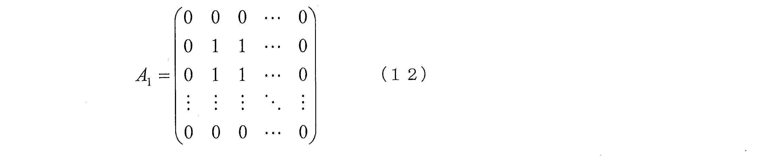
ここで、上記重み係数行列A1における値が0である成分は、第1のサブ領域に対する重み係数を示しており、値が1である成分は、第2のサブ領域に対する重み係数を表している。
上記式(12)のような重み係数行列A1を用いることによって、予測フィルタ係数導出部143が算出する予測フィルタ係数行列Pの各成分は、第1グループに対応する各画素に対して0となり、第2グループに対応する各画素に対しては、フィルタ係数h’(i、j)そのままの値となる。
図6は、M×Nタップのフィルタ参照領域Rの各画素に対応する、予測フィルタ係数Pの各成分を示す図である。
図6に示すように、フィルタ参照領域Rの周辺部の各画素に対応する予測フィルタ係数(すなわち上記第1グループに対応する予測フィルタ係数)の値は0であり、フィルタ参照領域Rの周辺部以外の各画素に対応する予測フィルタ係数(すなわち上記第2グループに対応する予測フィルタ係数)の値は、フィルタ係数h’(i、j)そのままの値である。
一般に、フィルタ参照領域Rの周辺部の各画素に対応するフィルタ係数は、0に近い値になる傾向がある。このような場合、符号化データ#1を生成する動画像符号化装置において、フィルタ参照領域Rの周辺部に対する重み係数を0として予測フィルタ係数を生成することによって、予測フィルタ係数算出に関わる演算量を削減することができ、また、符号化データ#1に含まれるフィルタ係数残差#13dの符号量を削減することができる。また、動画像復号装置1におけるフィルタ係数予測部140は、本例の動作を行うことによって、そのように生成された符号量の少ないフィルタ係数残差#13dに基づいて、予測フィルタ係数#140を導出することができる。
なお、本例における予測フィルタ係数導出部143は、式(6)を用いてフィルタ参照領域Rの中心画素に対する予測フィルタ係数を導出するような構成としてもよい。
(動画像符号化装置2)
本実施形態に係る動画像符号化装置2の構成について図7~図11を参照して説明する。動画像符号化装置2は、その一部に、H.264/MPEG-4 AVC、および、KTAソフトウェアに採用されている技術を含む復号装置である。
本実施形態に係る動画像符号化装置2の構成について図7~図11を参照して説明する。動画像符号化装置2は、その一部に、H.264/MPEG-4 AVC、および、KTAソフトウェアに採用されている技術を含む復号装置である。
図7は、動画像符号化装置2の構成を示すブロック図である。図7に示すように、動画像符号化装置2は、変換・量子化部21、可変長符号化部22、逆量子化・逆変換部23、バッファメモリ24、イントラ予測画像生成部25、インター予測画像生成部26、予測方式制御部28、動きベクトル冗長性削減部29、加算器31、減算器32、デブロッキングフィルタ50、および、適応フィルタ100’を備えている。
動画像符号化装置2には、マクロブロックに分割された入力画像#10が入力される。
動画像符号化装置2は、入力画像#10の符号化処理を行い、符号化データ#1を出力する。
変換・量子化部21は、マクロブロックに分割された入力画像#10と、後述する予測方式制御部28から出力される予測画像#28aとの差分画像#32を、DCT変換により、周波数成分へ変換した後、当該周波数成分の量子化を行い、量子化予測残差データ#21を生成する。ここで、上記量子化とは、上記周波数成分を整数値に対応付ける演算のことである。また、上記DCT変換、および、量子化は、マクロブロックを分割したブロック単位で行われる。以下では、処理の対象となるマクロブロックを「対象マクロブロック」と呼び、処理の対象となるブロックを「対象ブロック」と呼ぶ。
逆量子化・逆変換部23は、量子化予測残差データ#21の復号を行い、予測残差#23を生成する。具体的には、逆量子化・逆変換部23は、量子化予測残差データ#21の逆量子化、すなわち、量子化予測残差データ#21を構成する整数値の周波数成分への対応付け、および、当該周波数成分の逆DCT変換、すなわち、当該周波数成分に基づいた対象マクロブロックの画素成分への逆変換を行い、予測残差#23を生成する。
加算器31は、予測残差#23と、予測画像#28aとを加算し、復号画像#31を生成する。生成された復号画像#31は、デブロッキングフィルタ50に供給される。
デブロッキングフィルタ50は、復号画像#31における当該ブロック境界、またはマクロブロック境界に対してデブロッキング処理を施す。デブロッキング処理が施された画像データは、デブロック画像#50として出力される。デブロッキングフィルタ50は、動画像復号装置1の備えるデブロッキングフィルタ50と同様の構成である。
適応フィルタ100’は、デブロック画像#50に対してフィルタリングを施し、出力画像データ#100’をバッファメモリ24に対して出力する。また、適応フィルタ100’は、フィルタリングに用いたフィルタ係数と、予測されたフィルタ係数との残差であるフィルタ係数残差#102を可変長符号化部22に対して出力する。
また、適応フィルタ100’は、フィルタリングの対象となる領域を示すパラメータ、フィルタリングのタップ数を示すパラメータ、および、フィルタリングのオン/オフを指定するパラメータに関する情報であるフィルタパラメータ情報を可変長符号化部22に対して出力する。適応フィルタ100’の構成については、後述するため、ここでは説明を省略する。
イントラ予測画像生成部25は、バッファメモリ24に格納された出力画像データ#100’から局所復号画像#24a(対象マクロブロックと同じフレームの既復号領域)を抽出し、局所復号画像#24aに基づいてフレーム内予測を行い、イントラ予測画像#25を生成する。
インター予測画像生成部26は、入力画像#10上の対象ブロックに対し、既にフレーム全体が復号され、バッファメモリ24に格納された参照画像#24bを用いて、動きベクトル#27を算出し、割り付ける。算出された動きベクトル#27は、インター予測画像生成部26、動きベクトル冗長性削減部29に対して出力されると共に、バッファメモリ24に格納される。また、インター予測画像生成部26は、参照画像#24bに対し、ブロックごとに、動きベクトル#27に基づいた動き補償を行い、インター予測画像#26を生成する。
予測方式制御部28は、マクロブロック単位で、イントラ予測画像#25と、インター予測画像#26と、入力画像#10とを比較し、イントラ予測画像#25、または、インター予測画像#26のうち、何れか一方を選択し、予測画像#28aとして出力する。また、予測方式制御部28は、イントラ予測画像#25、または、インター予測画像#26のうち、何れを選択したのかを表す情報である予測モード#28bを出力する。予測画像#28aは減算器32に入力される。
予測モード#28bは、バッファメモリ24に格納されると共に、可変長符号化部22に入力される。
動きベクトル冗長性削減部29は、インター予測画像生成部26において上記対象ブロックに動きベクトル#27が割り付けられた後、他のブロックに割り付けられ、バッファメモリ24に格納された動きベクトル群#24cに基づいて予測ベクトルを算出する。また、動きベクトル冗長性削減部29は、当該予測ベクトルと、動きベクトル#27との差分をとり、差分動きベクトル#29を生成する。生成された差分動きベクトル#29は、可変長符号化部22に出力される。
可変長符号化部22は、量子化予測残差データ#21、差分動きベクトル#29、予測モード#28b、フィルタ係数残差#102、および、フィルタパラメータ情報に対して可変長符号化を行い、符号化データ#1を生成する。
減算器32は、対象マクロブロックに対し、入力画像#10と、予測画像#28aとの差分をとり、差分画像#32を出力する。
(適応フィルタ100’)
以下では、図8~図10を参照して、適応フィルタ100’の構成について説明する。図8は、適応フィルタ100’の構成を示すブロック図である。図8に示すように、適応フィルタ100’は、フィルタ処理部110’、フィルタパラメータ決定部120’、フィルタ係数導出部130’、フィルタ係数予測部140’、および、減算器102を備えている。
以下では、図8~図10を参照して、適応フィルタ100’の構成について説明する。図8は、適応フィルタ100’の構成を示すブロック図である。図8に示すように、適応フィルタ100’は、フィルタ処理部110’、フィルタパラメータ決定部120’、フィルタ係数導出部130’、フィルタ係数予測部140’、および、減算器102を備えている。
フィルタパラメータ決定部120’は、入力画像#10のサイド情報に基づいて、フィルタリングの参照画素数を示すパラメータ(タップ数)、および、フィルタリングのオン/オフ等を指定するパラメータ群(以下、フィルタパラメータ群と呼ぶ)を決定し、当該フィルタパラメータ群を含む情報であるフィルタパラメータ情報#120’を出力する。ここで、入力画像#10のサイド情報には、予測モード、動きベクトル、参照フレームを示す参照画像インデクス、および、量子化パラメータ、などが含まれる。
また、上記フィルタパラメータ群の決定方法は、本発明を限定するものではないが、例えば、フィルタパラメータ決定部120’は、入力画像#10を構成するブロックのブロックサイズ、または、入力画像#10を四分木(Quad-tree)により階層的に分割した場合の階層数などに応じて、上記フィルタパラメータ群を決定するような構成をとすることができる。
減算器102は、フィルタ係数#130’と、予測フィルタ係数#140’との差分をとることによって、フィルタ係数残差#102を生成し、出力する。
(フィルタ処理部110’)
フィルタ処理部110’は、デブロック画像#50に対して、フィルタ係数#130’を用いてフィルタリングを施すことによって、出力画像データ#100’を生成し、出力する。
フィルタ処理部110’は、デブロック画像#50に対して、フィルタ係数#130’を用いてフィルタリングを施すことによって、出力画像データ#100’を生成し、出力する。
フィルタ処理部110’におけるフィルタリング処理は、上述した動画像復号装置1におけるフィルタ処理部110におけるフィルタリング処理とほぼ同様である。
具体的には、フィルタ処理部110は、出力画像データ#100’の座標(x’、y’)における画素値S0(x’、y’)を上記式(1)によって表され、フィルタ係数#130’との加重線形和をとり、さらにフィルタ係数#101に基づいたオフセットを加算することよって算出する。ただし、フィルタ処理部110’においては、式(1)におけるフィルタ係数h(i、j)は、フィルタ係数#130’に対応しているものとする。
(フィルタ係数導出部130’)
フィルタ係数導出部130’は、フィルタパラメータ決定部120’から出力されたフィルタパラメータ情報#120’に基づき、入力画像#10とデブロック画像#50とを用いて、フィルタ係数#130’を導出する。導出されたフィルタ係数#130’は、フィルタ係数予測部140’、減算機102、および、フィルタ処理部110’に対して出力される。
フィルタ係数導出部130’は、フィルタパラメータ決定部120’から出力されたフィルタパラメータ情報#120’に基づき、入力画像#10とデブロック画像#50とを用いて、フィルタ係数#130’を導出する。導出されたフィルタ係数#130’は、フィルタ係数予測部140’、減算機102、および、フィルタ処理部110’に対して出力される。
フィルタ係数導出部130’は、フィルタ係数h(i、j)の値を、例えば、以下の式(13)によって与えられる、入力画像#10の各画素値と出力画像データ#100’の各画素値との二乗誤差E3を最小にするように導出する。

ここで、S(x、y)は、入力画像#10の座標(x、y)における画素値を表しており、SI(x、y)は、デブロック画像#50の座標(x、y)における画素値を表している。また、oはオフセットを表している。
このようにして導出されたフィルタ係数h(i、j)(1≦i≦M、1≦j≦N)は、フィルタ係数導出部130’から、フィルタ係数#130’として出力され、フィルタ処理部110’におけるフィルタリングに用いられる。
(フィルタ係数予測部140’)
フィルタ係数予測部140’は、動画像復号装置1の備えるフィルタ係数予測部140とほぼ同様の動作を行う。ただし、動画像符号化装置2においては、フィルタ係数予測部140’に供給されるフィルタ係数は、フィルタ係数#130’であり、フィルタ係数予測部140’が出力する予測フィルタ係数は、予測フィルタ係数#140’である。
フィルタ係数予測部140’は、動画像復号装置1の備えるフィルタ係数予測部140とほぼ同様の動作を行う。ただし、動画像符号化装置2においては、フィルタ係数予測部140’に供給されるフィルタ係数は、フィルタ係数#130’であり、フィルタ係数予測部140’が出力する予測フィルタ係数は、予測フィルタ係数#140’である。
図9は、フィルタ係数予測部140’の構成を示すブロック図である。図9に示すように、フィルタ係数予測部140’は、フィルタ係数格納部141’、重み係数算出部142’、および、予測フィルタ係数導出部143’を備えている。
フィルタ係数格納部141’は、動画像復号装置1におけるフィルタ係数格納部141とほぼ同様の動作を行う。ただし、フィルタ係数格納部141’に格納されているフィルタ係数には、符号化済みのフレームに対するフィルタリング処理においてすでに用いられたフィルタ係数#141’が含まれる。
フィルタ係数格納部141’に格納されている、符号化済みのフレームに対するフィルタリング処理においてすでに用いられたフィルタ係数#141’から構成されるフィルタ係数行列は、すでに説明した式(2)のように表すことができる。ただし、ここでは、フィルタ係数h’(i、j)は、符号化済みのフレームに対するフィルタリング処理においてすでに用いられたフィルタ係数#141’に対応している。
重み係数算出部142’は、動画像復号装置1における重み係数算出部142と同様に、フィルタ係数行列H’の各成分h’(i、j)に乗じる重み係数a(i、j)を算出する。重み係数算出部142’による重み係数a(i、j)の算出処理の具体例については、後述するためここでは説明を省略する。
予測フィルタ係数導出部143’は、動画像復号装置1における予測フィルタ係数導出部143と同様に、フィルタ係数格納部141’に格納されているフィルタ係数のうち、符号化済みのフレームに対するフィルタリング処理においてすでに用いられたフィルタ係数h’(i、j)と、重み係数算出部142’によって算出された重み係数a(i、j)とに基づいて、予測フィルタ係数p(i、j)を導出する。導出された予測フィルタ係数p(i、j)は、予測フィルタ係数#140’として出力される。
予測フィルタ係数p(i、j)を成分とする予測フィルタ係数行列Pは、例えば、すでに説明した式(5)のように表すことができる。
また、予測フィルタ係数導出部143’は、予測フィルタ係数p(i、j)のうち、フィルタ参照領域Rの中心画素に対応する予測フィルタ係数については、フィルタ参照領域Rの中心以外の画素に対するフィルタ係数の値に基づいて導出するような構成としてもよい。
例えば、予測フィルタ係数導出部143’は、フィルタ係数h(i、j)のうち、フィルタ参照領域Rの中心画素に対する予測フィルタ係数p_centerを、すでに説明した式(6)を用いて導出するような構成としてもよい。
式(6)を用いて予測フィルタ係数p_centerを算出することによって、フィルタ参照領域Rにおけるフィルタ係数h(i、j)の総和が1に近いという傾向を利用して、予測フィルタ係数の予測精度を効果的に向上させることができる。
一般に、フィルタ参照領域Rにおけるフィルタ係数の総和は、1に近い傾向がある。従って、上記の構成によれば、フィルタ係数残差#102の符号量を削減することができる。
以上のような各部を有する動画像符号化装置2において、可変長符号化部22、減算器102、および、フィルタ係数予測部140’は、フィルタ係数導出部130’から供給されるフィルタ係数#130’と、フィルタ係数#130’に基づいて予測された予測フィルタ係数#140’との残差であるフィルタ係数残差#102を符号化するフィルタ係数符号化装置を構成していると捉えることができる。したがって、本実施形態に係る動画像符号化装置2は、そのようなフィルタ係数符号化装置を備えている動画像符号化装置であると表現することもできる。
(予測フィルタ係数の算出処理の具体例)
以下では、フィルタ係数予測部140’による、予測フィルタ係数#140’の算出処理の具体例(具体例1-1’~具体例1-5’)について説明する。
以下では、フィルタ係数予測部140’による、予測フィルタ係数#140’の算出処理の具体例(具体例1-1’~具体例1-5’)について説明する。
(具体例1-1’)
以下では、フィルタ係数予測部140’による、予測フィルタ係数#140’の算出処理の第1の例について説明する。
以下では、フィルタ係数予測部140’による、予測フィルタ係数#140’の算出処理の第1の例について説明する。
本例では、フィルタ係数予測部140’は、(具体例1-1)において説明したフィルタ係数予測部140による予測フィルタ係数#140の算出処理に対応する動作を行う。
まず、重み係数算出部142’は、まず、フィルタ参照領域Rを、フィルタ参照領域Rの中心から周辺部に向かって、複数のグループ(サブ領域)に分割する(図5参照)。
続いて、重み係数算出部142’は、各グループに対する重み係数a(i、j)を、予め定められた値に設定する。ここで、上記予め定められた値としては、例えば、予め最小二乗法によって決定された値を用いればよい。
図10は、図5に示すフィルタ参照領域Rを構成するグループ1~グループ4に対応する重み係数a(i、j)を、異なる4つのシーケンス、および、異なる4つの量子化パラメータを用いて、200フレーム分のフレームに対して最小二乗法を適用することによって予め算出した結果を示すグラフである。ここで、当該最小二乗法において最小化すべき二乗誤差としては、すでに説明した式(10)によって表される二乗誤差E1をとった。
図10に示すように、最小二乗法によって求められた最適な重み係数は、フィルタ参照領域Rの中心により近い領域ほど、より大きな値となっている。これは、フィルタ参照領域Rの中心により近い領域ほど、フィルタ係数のフレーム間の相関がより大きくなるためである。
本例においては、重み係数算出部142’は、上記最小二乗法によって予め求められた各グループに対する最適な重み係数の値、またはその近似値を、各グループに属する各画素に対する重み係数に設定する。
すなわち、重み係数算出部142’は、例えば、グループ1に属する各画素に対する重み係数a_gr1を、a_gr1=1/4によって設定し、グループ2に属する各画素に対する重み係数a_gr2を、a_gr2=1/2によって設定し、グループ3に属する各画素に対する重み係数a_gr3を、a_gr3=5/8によって設定し、グループ4に属する各画素に対する重み係数a_gr4を、a_gr4=3/4によって設定する。
なお、上記のように各重み係数を1/8の倍数とするような場合、重み係数算出部142’は、グループ毎に、2、4、5、6、8を掛けて、丸め用の4を加算し3ビット右シフトするような整数演算を用いて上記重み係数#142を計算するような構成とすればよい。
重み係数算出部142’は、このようにして設定された各グループに対する重み係数a_grGを重み係数#142’として、予測フィルタ係数導出部143’に対して出力し、予測フィルタ係数導出部143’は、重み係数#142’を用いて、予測フィルタ係数#140’を導出する。
なお、グループ5に対する重み係数a_gr5の値は、重み係数a_gr1~a_gr4の値に応じて決定するような構成としてもよいし、予め定められた値(例えば1)を用いてもよい。
また、予測フィルタ係数導出部143’は、予測フィルタ係数#140’のうち、フィルタ参照領域Rの中心画素に対する予測フィルタ係数を、すでに説明した式(6)を用いて導出するような構成としてもよい。
フィルタ係数予測部140’は、以上のように、フィルタ参照領域Rを複数のサブ領域に分割し、それぞれのサブ領域に対して設定された重み係数を用いて予測フィルタ係数#140’を導出することができるので、フィルタ参照領域Rを分割しない従来の方法に比べて、フィルタ係数残差#102の符号量を削減することができる。
また、本例においては、重み係数算出部142’は、上記重み係数の値をメモリに格納しておくことにより、最小二乗法を用いた重み係数の算出処理を行うことなく、最適な重み係数を出力することができるので、最小二乗法を各フレームに対して用いる場合に比べて、計算量を削減しつつ、最適な重み係数を出力することができる。
したがって、本例においては、少ない計算量によって、フィルタ係数残差#102の符号量を削減することができる。
なお、上記の説明では、フィルタ参照領域Rが9×9タップである場合を例に挙げ説明を行ったが、本発明は、これに限定されるものではない。一般に、重み係数算出部142’は、M×Nタップのフィルタ参照領域Rの中心から周辺部に向かってグループ分けを行い、それぞれのグループに対する重み係数を、予め最小二乗法によって求められた最適な重み係数、または、その近似値に設定するような構成とすることができる。
また、重み係数算出部142’によるフィルタ参照領域Rの分割の方法は、上記の例に限定されるものではなく、フィルタ係数の特性などに応じて、最適な分割方法を採用すればよい。例えば、フィルタ係数毎に重み係数を分割することも好適である。
(具体例1-2’)
以下では、フィルタ係数予測部140’による、予測フィルタ係数#140’の算出処理の第2の例について説明する。
以下では、フィルタ係数予測部140’による、予測フィルタ係数#140’の算出処理の第2の例について説明する。
本例では、フィルタ係数予測部140’は、(具体例1-2)において説明したフィルタ係数予測部140による予測フィルタ係数#140の算出処理に対応する動作を行う。
重み係数算出部142’は、(具体例1-1’)と同様に、まず、フィルタ参照領域Rを、フィルタ参照領域Rの中心から周辺部に向かって、複数のグループに分割する。
フィルタ参照領域Rが9×9タップである場合の、重み係数算出部142’によるフィルタ参照領域Rの分割例は、図5に示したとおりである。
続いて、重み係数算出部142’は、フィルタ参照領域Rを構成する各グループに対する重み係数a_grG(G=1~Ng、Ngはフィルタ参照領域Rを構成するグループの総数、以下同様)を、当該フィルタ参照領域Rを構成する各グループに対応する領域であって、符号化済みのフィルタ係数を用いて算出する。
例えば、重み係数算出部142’は、まず、上記復号済みのフレーム上の領域であって、上記グループGの領域に対する重み係数a_grG’(s)を、すでに符号化されたフィルタ係数を用いて算出する。ここで、a_grG’(s)におけるインデックスsは、予測対象フレームから数えて、sフレーム前のフレームであることを示している。以下では、予測対象フレームから数えて、sフレーム前のフレームをフレームsと表記する。
具体的には、重み係数算出部142’は、フレームsに対する重み係数a_grG’(s)を、フレームsに対するフィルタ係数h(i、j)(s)の予測値を算出するために参照されたフィルタ係数h(i、j)(s_prev)と、フレームsに対するフィルタ係数h(i、j)(s)とを用いて、すでに説明した式(7)によって、算出する。
続いて、重み係数算出部142’は、重み係数a_grGを、算出した重み係数a_grG’(s)の代表値を用いて算出する。ここで、当該代表値としては、例えば、複数のフレームについて算出した重み係数a_grG’(s)の中央値を用いることができる。
本例においては、重み係数算出部142’は、重み係数a_grGを、すでに説明した式(8)によって算出する。
すなわち、重み係数算出部142’は、予測対象フレームから数えて1フレーム前からFフレーム前までのフレームの各々に対して算出された重み係数であって、グループGに対する重み係数a_grG’(1)~a_grG’(F)の中央値を、重み係数a_grGに設定する。なお、Fの具体的な値は、(具体例1-2)と同様に、予め定められている値を用いてもよいし、例えば、フィルタ参照領域Rのフレーム内の位置などに応じて決定される値を用いてもよい。
また、重み係数a_grG’(s)として、フレームsに対するフィルタ係数h(i、j)(s)の予測に用いた重み係数をそのまま用いるような構成としてもよい。
重み係数算出部142’は、このようにして設定された各グループに対する重み係数a_grGを重み係数#142’として、予測フィルタ係数導出部143’に対して出力し、予測フィルタ係数導出部143’は、重み係数#142’を用いて、予測フィルタ係数#140’を導出する。
一般に、フィルタ参照領域Rを構成する各グループに対する重み係数には、フレーム間の相関がある。すなわち、符号化済みのフレーム上の各領域に対してすでに算出された重み係数は、予測対象フレームに対する予測フィルタ係数の導出に対しても適切な値であるという傾向がある。したがって、フィルタ係数予測部140’は、本例のような動作を行うことによって、フィルタ係数残差#102の符号量を削減することができる。
また、本例においては、符号化済みのフレーム上の各領域に対してすでに算出された重み係数の中央値を用いているため、各領域において、他のフレームに対する重み係数と大きく異なるような重み係数が存在するような場合であっても、そのような重み係数の影響をほとんど受けない予測フィルタ係数#140’を導出することができる。
なお、予測フィルタ係数導出部143’は、式(6)を用いてフィルタ参照領域Rの中心画素に対する予測フィルタ係数を導出するような構成としてもよい。
なお、重み係数算出部142’による上記の動作は、例えば、重み係数算出部142が、復号済みのフレーム上の各領域に対してすでに算出された重み係数を格納しておくメモリを備えることによって可能となる。
(具体例1-3’)
以下では、フィルタ係数予測部140’による、予測フィルタ係数#140’の算出処理の第3の例について説明する。
以下では、フィルタ係数予測部140’による、予測フィルタ係数#140’の算出処理の第3の例について説明する。
本例では、フィルタ係数予測部140’は、(具体例1-3)において説明したフィルタ係数予測部140による予測フィルタ係数#140の算出処理に対応する動作を行う。
本例においては、重み係数算出部142’は、上述した(具体例1-2’)における代表値として、平均値を用いることによって、フィルタ参照領域Rを構成する各グループに対する重み係数を算出する。
すなわち、本例においては、重み係数算出部142’は、重み係数a_grGを、式(9)によって算出する。
すなわち、重み係数算出部142’は、予測対象フレームから数えて1フレーム前からFフレーム前までのフレームの各々に対して算出された重み係数であって、グループGに対する重み係数a_grG’(1)~a_grG’(F)の平均値を、重み係数a_grGに設定する。
重み係数算出部142’の他の動作は、(具体例1-2’)で説明した動作と同様である。
(具体例1-2’)で述べたように、フィルタ参照領域Rを構成する各グループに対する重み係数には、フレーム間の相関がある。すなわち、符号化済みのフレーム上の各領域に対してすでに算出された重み係数は、予測対象フレームに対する予測フィルタ係数の導出に対しても適切な値であるという傾向がある。したがって、フィルタ係数予測部140’は、本例のような動作を行うことによって、フィルタ係数残差#102の符号量を削減することができる。
また、本例においては、符号化済みのフレーム上の各領域に対してすでに算出された重み係数の平均値を用いているため、各領域における重み係数の値のばらつきが大きいような場合であっても、適切な予測フィルタ係数#140’を導出することができる。
また、(具体例1-2’),および、(具体例1-3’)においては、代表値として中央値、および、平均値を用いる構成について説明を行ったが、本発明はこれに限定されるものではない。例えば、代表値として、重み係数のセットから最大値および最小値を除いた後に平均をとることによって得られる値や、重み付きの平均値、すなわち、重み係数の加重平均を用いても良い。
(具体例1-4’)
以下では、フィルタ係数予測部140’による、予測フィルタ係数#140’の算出処理の第4の例について説明する。
以下では、フィルタ係数予測部140’による、予測フィルタ係数#140’の算出処理の第4の例について説明する。
本例では、フィルタ係数予測部140’は、(具体例1-4)において説明したフィルタ係数予測部140による予測フィルタ係数#140の算出処理に対応する動作を行う。
重み係数算出部142’は、(具体例1-1’)と同様に、まず、フィルタ参照領域Rを、フィルタ参照領域Rの中心から周辺部に向かって、複数のグループに分割する。
フィルタ参照領域Rが9×9タップである場合の、重み係数算出部142’によるフィルタ参照領域Rの分割例は、図5に示したとおりである。
続いて、重み係数算出部142’は、最小二乗法によって、重み係数a(i、j)を算出する。
具体的には、重み係数算出部142’は、すでに説明した式(10)によって表される二乗誤差E1を最小にするように、重み係数a(i、j)を算出する。ただし、式(10)におけるh(i、j)(t_prev)は、本例においては、符号化済みフィルタ係数であって、フィルタ係数h(i、j)(t)に対応する予測フィルタ係数の算出のために参照されるフィルタ係数を表すものとする。
本例における重み係数算出部142’による重み係数a(i、j)の具体的な算出処理は、(具体例1-4)と同様である。
また、重み係数算出部142’は、最小二乗法を用いて算出された重み係数a(i、j)を、フィルタ参照領域を構成するグループ毎に平均することによって、各グループに対する重み係数a_grGを算出し、重み係数#142’として予測フィルタ係数導出部143’に出力する。
予測フィルタ係数導出部143’は、重み係数#142’を用いて、予測フィルタ係数#140’を導出する。
このように、重み係数算出部142’が、最小二乗法を用いて、各グループに対する重み係数を算出することによって、フィルタ係数残差#102の符号量を削減することができる。
なお、重み係数算出部142’は、(具体例1-4)と同様に、最小二乗法を用いて算出された重み係数a(i、j)の、フィルタ参照領域を構成するグループ毎に中央値をとることによって、各グループに対する重み係数a_grGを算出するような構成としてもよい。
また、重み係数算出部142’は、(具体例1-4)と同様に、各グループに対する重み係数a_grGを、式(11)を用いて、最小二乗法によって算出するような構成としてもよい。
また、予測フィルタ係数導出部143’は、式(6)を用いてフィルタ参照領域Rの中心画素に対する予測フィルタ係数を導出するような構成としてもよい。
(具体例1-5’)
以下では、フィルタ係数予測部140’による、予測フィルタ係数#140’の算出処理の第5の例について説明する。
以下では、フィルタ係数予測部140’による、予測フィルタ係数#140’の算出処理の第5の例について説明する。
本例では、フィルタ係数予測部140’は、(具体例1-5)において説明したフィルタ係数予測部140による予測フィルタ係数#140の算出処理に対応する動作を行う。
重み係数算出部142’は、まず、フィルタ参照領域Rを、フィルタ参照領域Rの周辺部である第1のサブ領域と、第1のサブ領域以外の領域である第2のサブ領域とに分割する。ここで、フィルタ参照領域Rの周辺部とは、フィルタ参照領域R内の領域であって、フィルタ参照領域Rの外縁に接するか、または、フィルタ参照領域Rの外縁の近傍の領域である(以下同様)。
続いて、重み係数算出部142’は、第1のサブ領域に対する重み係数の値を0に設定し、第2のサブ領域に対する重み係数の値を1に設定する。
このようにして重み係数算出部142によって算出された重み係数a(i、j)から構成される重み係数行列A1は、式(12)のように表すことができる。
ここで、上記重み係数行列A1における値が0である成分は、第1のサブ領域に対する重み係数を示しており、値が1である成分は、第2のサブ領域に対する重み係数を表している。
上記式(12)のような重み係数行列A1を用いることによって、予測フィルタ係数導出部143’が算出する予測フィルタ係数行列Pの各成分は、第1グループに対応する各画素に対して0となり、第2グループに対応する各画素に対しては、フィルタ係数h’(i、j)そのままの値となる(図6参照)。
一般に、フィルタ参照領域Rの周辺部の各画素に対応するフィルタ係数は、0に近い値になる傾向がある。このような場合、本例のように、フィルタ参照領域の周辺部Rに対応する予測フィルタ係数の値を0とすることによって、予測フィルタ係数算出に関わる演算量を削減することができ、また、フィルタ係数残差#101の符号量を削減することができる。
例えば、予測対象フレームに対するフィルタ係数h(i、j)のうち、フィルタ参照領域Rの周辺部の画素に対応するフィルタ係数の値が0.1であり、符号化済みのフレームに対するフィルタリング処理においてすでに用いられたフィルタ係数h’(i、j)のうち、上記フィルタ参照領域Rの周辺部の画素に対応するフィルタ係数の値が-0.1である場合、フィルタ係数h’(i、j)をそのまま予測フィルタ係数としてフィルタ係数残差を生成すると、上記画素に対応するフィルタ係数残差の値は0.2となるが、本例のように、フィルタ参照領域Rの周辺部の画素に対応する予測フィルタ係数の値を0としてフィルタ係数残差を生成すると、上記画素に対応するフィルタ係数残差の値は0.1となる。
このように、フィルタ参照領域Rの周辺部の画素に対応する予測フィルタ係数を0とすることによって、フィルタ係数残差#102の符号量を削減することができる。
なお、本例における予測フィルタ係数導出部143は、式(6)を用いてフィルタ参照領域Rの中心画素に対する予測フィルタ係数を導出するような構成としてもよい。
(符号化データ#1のデータ構造)
以下では、動画像符号化装置2によって生成され、動画像復号装置1によって復号される符号化データ#1のデータ構造について、図11の(a)~(b)を参照して説明する。
以下では、動画像符号化装置2によって生成され、動画像復号装置1によって復号される符号化データ#1のデータ構造について、図11の(a)~(b)を参照して説明する。
図11の(a)は、動画像符号化装置2によって生成され、動画像復号装置1に参照される符号化データ#1のスライスごとのビットストリーム#BSを示している。図11の(a)に示すように、ビットストリーム#BSは、フィルタパラメータ情報FP、フィルタ係数残差情報RC、マクロブロック情報MB1~MBNを含んでいる。ここで、フィルタ係数残差情報RCは、動画像符号化装置2において生成されたフィルタ係数残差#102を含む情報である。マクロブロック情報MB1~MBNは、スライス内に存在するマクロブロックの復号に用いられる情報である。Nはスライス内に存在するマクロブロックの数を表している。なお、マクロブロック情報は、予測モード、動きベクトル、参照画像インデクス、量子化パラメータ、量子化予測残差データなどを含む。
図11の(b)は、フィルタパラメータ情報FPの構成の一例を示している。
図11の(b)に示すように、フィルタパラメータ情報FPは、フィルタリングの参照画素数を示すパラメータ(タップ数)、および、フィルタリングのオン/オフを指定するオン/オフ指定情報を含む。
また、フィルタパラメータ情報FPは、動画像符号化装置2において算出された重み係数#142’を示す重み係数情報を含むような構成としてもよい。
以下では、動画像符号化装置2において説明した具体例に対応する符号化データ#1の構成について説明する。
(構成例1-1)
動画像符号化装置2の備えるフィルタ係数予測部140’が、(具体例1-1’)のように動作する場合の、符号化データ#1の構成例は以下の通りである。
動画像符号化装置2の備えるフィルタ係数予測部140’が、(具体例1-1’)のように動作する場合の、符号化データ#1の構成例は以下の通りである。
本例においては、フィルタ係数残差は、(具体例1-1’)に説明した処理によって算出された予測フィルタ係数#140’を用いて生成されたフィルタ係数残差#102を含む。
また、符号化データ#1におけるフィルタパラメータ情報FPの重み係数情報には、(具体例1-1’)において算出された重み係数#142’を含むような構成としてもよい。また、重み係数情報には、重み係数#142’そのものではなく、重み係数#142’を示すパラメータを含むような構成としても良い。例えば、各グループの重み係数が2/8、4/8、5/8、6/8、8/8といった、1/8の倍数である場合は、パラメータとして、各重み係数の分子(2、4、5、6、8)と、分母(8)をパラメータとして、重み係数情報に含めるような構成となる。
また、動画像復号装置1の備えるメモリに、重み係数#142’が、予め記録されている場合には、フィルタパラメータ情報FPの重み係数情報を含まない構成としてもよい。
また、動画像復号装置1の備えるメモリに、重み係数#142’が、予め記録されている場合には、フィルタパラメータ情報FPの重み係数情報を含まない構成としてもよい。
また、フィルタ対象領域情報には、フィルタ参照領域Rが、どのように分割されているかを示す情報、例えば、図5に示すようにグループ分けされていることを示す情報が含まれていてもよい。
(構成例1-2)
動画像符号化装置2の備えるフィルタ係数予測部140’が、(具体例1-2’)のように動作する場合の、符号化データ#1の構成例は以下の通りである。
動画像符号化装置2の備えるフィルタ係数予測部140’が、(具体例1-2’)のように動作する場合の、符号化データ#1の構成例は以下の通りである。
本例においては、フィルタ係数残差は、(具体例1-2’)に説明した処理によって算出された予測フィルタ係数#140’を用いて生成されたフィルタ係数残差#102を含む。
また、(具体例1-2’)において算出された重み係数は、動画像復号装置1において算出可能であるため、符号化データ#1におけるフィルタパラメータ情報FPには、重み係数情報を含まなくて良い。
また、フィルタ対象領域情報には、フィルタ参照領域Rが、どのように分割されているかを示す情報、例えば、図5に示すようにグループ分けされていることを示す情報が含まれていてもよい。
(構成例1-3)
動画像符号化装置2の備えるフィルタ係数予測部140’が、(具体例1-3’)のように動作する場合の、符号化データ#1の構成例は以下の通りである。
動画像符号化装置2の備えるフィルタ係数予測部140’が、(具体例1-3’)のように動作する場合の、符号化データ#1の構成例は以下の通りである。
本例においては、フィルタ係数残差は、(具体例1-3’)に説明した処理によって算出された予測フィルタ係数#140’を用いて生成されたフィルタ係数残差#102を含む。
また、(具体例1-3’)において算出された重み係数は、動画像復号装置1において算出可能であるため、符号化データ#1におけるフィルタパラメータ情報FPには、重み係数情報を含まなくて良い。
また、フィルタ対象領域情報には、フィルタ参照領域Rが、どのように分割されているかを示す情報、例えば、図5に示すようにグループ分けされていることを示す情報が含まれていてもよい。
(構成例1-4)
動画像符号化装置2の備えるフィルタ係数予測部140’が、(具体例1-4’)のように動作する場合の、符号化データ#1の構成例は以下の通りである。
動画像符号化装置2の備えるフィルタ係数予測部140’が、(具体例1-4’)のように動作する場合の、符号化データ#1の構成例は以下の通りである。
本例においては、フィルタ係数残差は、(具体例1-4’)に説明した処理によって算出された予測フィルタ係数#140’を用いて生成されたフィルタ係数残差#102を含む。
また、(具体例1-4’)において算出された重み係数は、動画像復号装置1において算出可能であるため、符号化データ#1におけるフィルタパラメータ情報FPには、重み係数情報を含まなくて良い。
また、フィルタ対象領域情報には、フィルタ参照領域Rが、どのように分割されているかを示す情報、例えば、図5に示すようにグループ分けされていることを示す情報が含まれていてもよい。
(構成例1-5)
動画像符号化装置2の備えるフィルタ係数予測部140’が、(具体例1-5’)のように動作する場合の、符号化データ#1の構成例は以下の通りである。
動画像符号化装置2の備えるフィルタ係数予測部140’が、(具体例1-5’)のように動作する場合の、符号化データ#1の構成例は以下の通りである。
本例においては、フィルタ係数残差は、(具体例1-5’)に説明した処理によって算出された予測フィルタ係数#140’を用いて生成されたフィルタ係数残差#102を含む。
また、(具体例1-5’)において算出された重み係数は、動画像復号装置1において算出可能であるため、符号化データ#1におけるフィルタパラメータ情報FPには、重み係数情報を含まなくて良い。
また、フィルタ対象領域情報には、フィルタ参照領域Rが、どのように分割されているかを示す情報、例えば、図5に示すようにグループ分けされていることを示す情報が含まれていてもよい。
〔実施形態2〕
(動画像復号装置3)
本実施形態に係る動画像復号装置3の構成について図12~図14を参照して説明する。図12は、動画像復号装置3の構成を示すブロック図である。なお、図12では、図1において示した各ブロックと同一のブロックに関しては、同一の参照符号を付し、その説明を省略する。
(動画像復号装置3)
本実施形態に係る動画像復号装置3の構成について図12~図14を参照して説明する。図12は、動画像復号装置3の構成を示すブロック図である。なお、図12では、図1において示した各ブロックと同一のブロックに関しては、同一の参照符号を付し、その説明を省略する。
図12に示すように、動画像復号装置3は、可変長符号復号部51、動きベクトル復元部14、バッファメモリ15、インター予測画像生成部16、イントラ予測画像生成部17、予測方式決定部18、逆量子化・逆変換部19、加算器20、デブロッキングフィルタ50、および、適応フィルタ200を備えている。
動画像復号装置3は、符号化データ#5を受け、復号画像#6を出力する。
可変長符号復号部51は、符号化データ#5を可変長復号し、差分動きベクトル#13a、サイド情報#13b、量子化予測残差データ#13c、フィルタ係数残差#13d、フィルタパラメータ情報#13e、および、フィルタ係数算出方法を示すフラグ#51を出力する。
適応フィルタ200は、符号化データ#5から復号されたフラグ#51が示すフィルタ係数算出手法に従ってフィルタ係数残差#13dに基づいてフィルタ係数を算出し、デブロック画像#50に対して当該フィルタ係数を用いたフィルタリングを行うことによって出力画像データ#200を生成する。出力画像データ#200は、バッファメモリ15に対して供給される。なお、適応フィルタ200におけるフィルタリング処理は、符号化データ#5から復号されたサイド情報#13b、および、フィルタパラメータ情報#13eに含まれるパラメータに基づいて行われる。
以下では、図13を参照して、適応フィルタ200の構成について説明する。
(適応フィルタ200)
図13は、適応フィルタ200の構成を示すブロック図である。なお、図13では、図2において示した各ブロックと同一のブロックに関しては、同一の参照符号を付し、その説明を省略する。図13に示すように、適応フィルタ200は、フィルタ処理部110、フィルタ係数予測部210、および、加算器202を備えている。
図13は、適応フィルタ200の構成を示すブロック図である。なお、図13では、図2において示した各ブロックと同一のブロックに関しては、同一の参照符号を付し、その説明を省略する。図13に示すように、適応フィルタ200は、フィルタ処理部110、フィルタ係数予測部210、および、加算器202を備えている。
加算器202は、符号化データ#5から復号されたフィルタ係数残差#13dとフィルタ係数予測部210より出力された予測フィルタ係数#210とを加算することによって、フィルタ係数#202を生成し、出力する。
フィルタ係数予測部210は、フィルタ係数算出方法を示すフラグ#51で示される方法に従い、フィルタ係数#202のうち、復号済みのフレームに対するフィルタリング処理においてすでに用いられたフィルタ係数に基づいて、予測フィルタ係数#210を算出する。予測フィルタ係数#210は加算器202に対して出力される。
図14は、フィルタ係数予測部210の構成を示すブロック図である。なお、図14では、図4において示した各ブロックと同一のブロックに関しては、同一の参照符号を付し、その説明を省略する。図14に示すように、フィルタ係数予測部210は、フィルタ係数格納部141、重み係数算出部142、および、予測フィルタ係数導出部211を備えている。
フィルタ係数予測部210は、フラグ#51に応じて、(具体例1-1)~(具体例1-5)において説明した予測フィルタ係数#140と同様の予測フィルタ係数#210を出力するか、または、復号済みのフレームに対するフィルタリング処理においてすでに用いられたフィルタ係数#141を予測フィルタ係数#210として出力する。
より具体的には、フィルタ係数予測部210の備える予測フィルタ係数導出部211は、例えば、フラグ#51の値が1である場合、復号済みフィルタ係数#141と、重み係数算出部142によって算出された重み係数#142とに基づいて、式(5)で表される予測フィルタ係数行列Pの各成分を導出し、予測フィルタ係数#210として出力する。ここで、重み係数算出部142における重み係数の算出方法としては、すでに説明した(具体例1-1)~(具体例1-5)の何れかを用いればよい。
一方で、フラグ#51の値が0である場合には、予測フィルタ係数導出部211は、復号済みフィルタ係数#141を予測フィルタ係数#210として出力する。
このように、フィルタ係数予測部210は、フラグ#51に応じて、復号済みフィルタ係数#141を予測フィルタ係数#210として出力するか、または、フィルタ参照領域Rの各グループに対して個別に算出された重み係数を用いて導出されたフィルタ係数を予測フィルタ係数#210として出力する。
フィルタ係数予測部210は、このような動作を行うことによって、より少ない符号量のフィルタ係数残差#13dを含む符号化データ#5を復号することができる。
フィルタ係数予測部210は、フラグ#51を参照することなく、復号済みフィルタ係数#141を予測フィルタ係数#210として出力するか、または、フィルタ参照領域Rの各グループに対して個別に算出された重み係数を用いて導出されたフィルタ係数を予測フィルタ係数#210として出力するような構成としてもよい。
例えば、重み係数算出部142が、9×9タップのフィルタ参照領域を構成する各グループに対し、実施形態1の(具体例1-2)において説明した方法で重み係数#142を算出した場合、グループGに対する重み係数a_grGが、予め定められた値thより小さい場合には、重み係数a_grGを用いて、実施形態1の(具体例1-2)に示した方法と同様の方法に従い、予測フィルタ係数#210を導出し、そうでない場合には、復号済みフィルタ係数#141を予測フィルタ係数#210として出力するような構成としてもよい。
一般に、重み係数算出部142によって算出される重み係数#142は、フレーム間の相関を表している。換言すれば、値のより小さい重み係数#142が割り付けられた領域は、当該領域におけるフィルタ係数のフレーム間の相関がより低い。
上記の構成に対応した構成を有する動画像符号化装置によれば、フィルタ係数のフレーム間の相関がより低い領域に対するフィルタ係数残差の符号量をより効果的に削減することができる。また、上記の構成によれば、そのように生成された符号化データを復号することができる。
なお、上記構成は、重み係数算出部142が、実施形態1の他の具体例に対応する動作を行う場合に対しても同様に適用することができる。
なお、本実施形態においても、可変長符号復号部51、加算器202、および、フィルタ係数予測部210は、フィルタ係数残差#13dに基づいて、フィルタ係数#202を復号するフィルタ係数復号装置を構成していると捉えることができる。
(動画像符号化装置4)
本実施形態に係る動画像符号化装置4の構成について図15~図17を参照して説明する。図15は、動画像符号化装置4の構成を示すブロック図である。なお、図15では、図7において示した各ブロックと同一のブロックに関しては、同一の参照符号を付し、その説明を省略する。
本実施形態に係る動画像符号化装置4の構成について図15~図17を参照して説明する。図15は、動画像符号化装置4の構成を示すブロック図である。なお、図15では、図7において示した各ブロックと同一のブロックに関しては、同一の参照符号を付し、その説明を省略する。
図15に示すように、動画像符号化装置4は、変換・量子化部21、逆量子化・逆変換部23、バッファメモリ24、イントラ予測画像生成部25、インター予測画像生成部26、予測方式制御部28、動きベクトル冗長性削減部29、加算器31、減算器32、デブロッキングフィルタ50、可変長符号化部41、および、適応フィルタ200’を備えている。
動画像符号化装置4には、隣接する複数の画素から構成されるブロック画像に分割された入力画像#4が入力される。
動画像符号化装置4は、入力画像#4の符号化処理を行い、符号化データ#5を出力する。
可変長符号化部41は、量子化予測残差データ#21、差分動きベクトル#29、予測モード#28b、フィルタ係数の予測方法を示すフラグ#220、および、フィルタ係数残差#102に対して可変長符号化を行い、符号化データ#5を生成する。
適応フィルタ200’は、デブロック画像#50に対してフィルタリングを施すことによって出力画像データ#200’を生成し、バッファメモリ24に対して出力する。また、適応フィルタ200’は、フィルタリングに用いたフィルタ係数と、予測されたフィルタ係数との残差であるフィルタ係数残差#102を可変長符号化部41に対して出力する。また、適応フィルタ200’は、フィルタ係数の予測方法を示すフラグ#220を可変長符号化部41に対して出力する。
以下では、適応フィルタ200’の構成例について、説明する。
(適応フィルタ200’の構成例1)
図16の(a)は、適応フィルタ200’の第1の構成例を示している。本例においては、適応フィルタ200’は、フィルタ係数予測部210’において算出される重み係数の値に応じて選択された予測フィルタ係数を出力する。
図16の(a)は、適応フィルタ200’の第1の構成例を示している。本例においては、適応フィルタ200’は、フィルタ係数予測部210’において算出される重み係数の値に応じて選択された予測フィルタ係数を出力する。
図16の(a)に示すように、適応フィルタ200’は、フィルタ処理部110’、フィルタパラメータ決定部120’、フィルタ係数導出部130’、フィルタ係数予測部210’、減算器201a、および、予測手段選択部220aを備えている。
図16の(a)においては、図8において示した各ブロックと同一のブロックに関しては、同一の参照符号を付し、その説明を省略する。
減算器201aは、フィルタ係数#130’と、予測フィルタ係数#210’との差分をとることによって、フィルタ係数残差#102を生成し、可変長符号化部41に対して出力する。
(フィルタ係数予測部210’)
図17は、フィルタ係数予測部210’の構成を示すブロック図である。なお、図17では、図9において示した各ブロックと同一のブロックに関しては、同一の参照符号を付し、その説明を省略する。図17に示すように、フィルタ係数予測部210’は、フィルタ係数格納部141’、重み係数算出部142’および、予測フィルタ係数導出部211’を備えている。
図17は、フィルタ係数予測部210’の構成を示すブロック図である。なお、図17では、図9において示した各ブロックと同一のブロックに関しては、同一の参照符号を付し、その説明を省略する。図17に示すように、フィルタ係数予測部210’は、フィルタ係数格納部141’、重み係数算出部142’および、予測フィルタ係数導出部211’を備えている。
なお、フィルタ係数予測部210’における重み係数算出部142’によって算出された重み係数#142’は、予測手段選択部220aに対しても供給される。
予測フィルタ係数導出部211’は、重み係数#142’が予測手段選択部220aに対して供給された後、予測手段選択部220aから供給されるフラグ#220の値に応じて、(具体例1-1’)~(具体例1-5’)の何れかにおいて説明した予測フィルタ係数#140’と同様の予測フィルタ係数#210’を出力するか、または、符号化済みのフレームに対するフィルタリング処理においてすでに用いられたフィルタ係数#141’を予測フィルタ係数#210’として出力する。
(予測手段選択部220a)
予測手段選択部220aは、重み係数#142’の値が予め定められた値以上であるか、あるいは、そうでないかに応じて、フラグ#220を出力する。
予測手段選択部220aは、重み係数#142’の値が予め定められた値以上であるか、あるいは、そうでないかに応じて、フラグ#220を出力する。
例えば、重み係数算出部142’が、9×9タップのフィルタ参照領域を構成する各グループに対し、実施形態1の(具体例1-2’)において説明した方法で重み係数#142’を算出した場合、グループGに対する重み係数a_grGが、予め定められた値thより小さい場合は、重み係数a_grGを用いて予測フィルタ係数を導出することを示すフラグ#220を出力する。一方で、グループGに対する重み係数a_grGが、予め定められた値th以上である場合には、予測手段選択部220aは、符号化済みのフレームに対するフィルタリング処理においてすでに用いられたフィルタ係数#141’を出力することを示すフラグ#220を出力する。
なお、上記グループGとしては、具体的には、グループ1~グループ4の何れかのグループをとればよい。また、重み係数a_grGに替えて、各グループに対する重み係数a_gr1~a_gr4の平均値を用いてもよい。
フラグ#220は、可変長符号化部41に対して、出力されると共に、予測フィルタ係数導出部211において参照される。
一般に、重み係数算出部142’によって算出される重み係数#142’は、フレーム間の相関を表している。換言すれば、値のより小さい重み係数#142’が割り付けられた領域は、当該領域におけるフィルタ係数のフレーム間の相関がより低い。
一方で、フィルタ係数予測部210’は、重み係数#142’を用いて予測フィルタ係数#210’を導出することによって、フィルタ係数のフレーム間の相関がより低い領域に対する、フィルタ係数残差#102の符号量をより効果的に削減することができる。また、フィルタ係数のフレーム間の相関がより高い領域に対しては、重み係数#142’を用いずに予測フィルタ係数#210’を出力することによって、計算量を削減できる。
従って、本例のような動作を行うことによって、フィルタ係数予測部210’は、計算量を削減しつつ、フィルタ係数残差#102の符号量を効果的に削減することができる。
なお、上記の説明では、9×9タップのフィルタ参照領域において、(具体例1-2’)を例に挙げ説明を行ったが、本発明は、これに限定されるものではない。予測手段選択部220aによる上記の選択処理は、重み係数算出部142’が、実施形態1の(具体例1-1’)~(具体例1-5’)において説明した方法で重み係数#142’を算出する場合に対して適用することができる。
なお、本構成例によって生成された符号化データ#5を復号する動画像復号装置は、重み係数算出部142’に対応する構成によって算出される重み係数の値を、上記予め定められた閾値thと比較することによって、フラグ#220を参照することなく、復号済みフィルタ係数を予測フィルタ係数として復号処理を行うか、または、フィルタ参照領域Rの各グループに対して個別に算出された重み係数を用いて導出されたフィルタ係数を予測フィルタ係数として復号処理を行うこともできる。
したがって、本構成例においては、予測手段選択部220aは、フラグ#220を、可変長符号化部41に対して供給しないような構成としてもよい。
このような構成とすることによって、符号化データ#5の符号量を削減することができる。
(適応フィルタ200’の構成例2)
続いて、適応フィルタ200’の第2の構成例について説明する。図16の(b)は、適応フィルタ200’の第2の構成例を示している。
続いて、適応フィルタ200’の第2の構成例について説明する。図16の(b)は、適応フィルタ200’の第2の構成例を示している。
図16の(b)に示すように、本例においては、適応フィルタ200’は、(適応フィルタ200’の構成例1)において説明した、予測手段選択部220aに替えて、予測手段選択部220bを備えている。
本例における予測フィルタ係数導出部211は、(具体例1-1’)~(具体例1-5’)の何れかにおいて説明した予測フィルタ係数#140’と同様の予測フィルタ係数と、符号化済みのフレームに対するフィルタリング処理においてすでに用いられたフィルタ係数#141’とを予測フィルタ係数#210’として出力する。
また、減算器201bは、フィルタ係数#130’と、予測フィルタ係数#210’との差分をとることによって、フィルタ係数残差#201bを生成し、予測手段選択部220bに対して出力する。なお、フィルタ係数残差#201bには、重み係数#142’を用いて導出された予測フィルタ係数を用いて算出されたフィルタ係数残差#RC1と、符号化済みのフレームに対するフィルタリング処理においてすでに用いられたフィルタ係数を用いて算出されたフィルタ係数残差#RC2とが含まれる。
(予測手段選択部220b)
予測手段選択部220bは、フィルタ係数残差#RC1と、フィルタ係数残差#RC2とを比較し、より小さいフィルタ係数残差をフィルタ係数残差#102として出力する。また、図示しないが、予測手段選択部220bへの入力をフィルタ係数残差の符号量とし、両者の比較を行い、より小さい符号量に対応するフィルタ係数残差を、フィルタ係数残差#102として出力する構成としても良い。
予測手段選択部220bは、フィルタ係数残差#RC1と、フィルタ係数残差#RC2とを比較し、より小さいフィルタ係数残差をフィルタ係数残差#102として出力する。また、図示しないが、予測手段選択部220bへの入力をフィルタ係数残差の符号量とし、両者の比較を行い、より小さい符号量に対応するフィルタ係数残差を、フィルタ係数残差#102として出力する構成としても良い。
また、予測手段選択部220bは、フィルタ係数残差#RC1を出力する場合には、重み係数#142’を用いて予測フィルタ係数が導出されたことを示すフラグ#220を出力し、フィルタ係数残差#RC2を出力する場合には、符号化済みのフレームに対するフィルタリング処理においてすでに用いられたフィルタ係数を用いて予測フィルタ係数が算出されたことを示すフラグ#220を出力する。
適応フィルタ200’が以上のような構成をとることによって、適応フィルタ200’は、符号量のより少ないフィルタ係数残差#102を出力することができる。
なお、本実施形態においても、可変長符号化部41、減算器201a(または減算器201b)、および、フィルタ係数予測部210’は、フィルタ係数#130’を符号化するフィルタ係数符号化装置を構成していると捉えることができる。
(符号化データ#5のデータ構造)
以下では、動画像符号化装置4によって生成された符号化データ#5のデータ構造について説明する。
以下では、動画像符号化装置4によって生成された符号化データ#5のデータ構造について説明する。
符号化データ#5のデータ構造は、図11の(a)~(b)を用いてすでに説明した符号化データ#1のデータ構造とほぼ同様であるが、以下の点において異なる。
まず、予測手段選択部220bを含む構成の場合、符号化データ#5におけるフィルタパラメータ情報FPには、予測フィルタ係数が、重み係数を用いて導出されたのか、または、符号化済みのフレームに対するフィルタリング処理においてすでに用いられたフィルタ係数を用いて算出されたのかを示すフラグが含まれる。また、上記フラグは、符号化データ#5におけるフィルタパラメータ情報FPに含まれる構成となる。
符号化データ#5を復号する動画像復号装置3は、当該フラグを参照することによって、動画像符号化装置4において用いられた方法と同じ方法を用いて予測フィルタ係数を導出することができる。したがって、符号化データ#5を復号する動画像復号装置3は、当該フラグを参照することによって、符号量のより少ないフィルタ係数残差#102を含む符号化データ#5を復号することができる。
また、上記フラグが、予測フィルタ係数が符号化済みのフレームに対するフィルタリング処理においてすでに用いられたフィルタ係数を用いて算出されたことを示している場合には、符号化データ#5は、重み係数情報を含まないような構成とすることができる。
このような構成とすることにより、符号化データ#5の符号量をさらに削減することができる。
また、その場合、符号化データ#5に含まれるフィルタ係数残差は、符号化済みのフレームに対するフィルタリング処理においてすでに用いられたフィルタ係数を用いて導出されたフィルタ係数残差に対応する。
(付記事項)
発明者は、周辺部のフィルタ係数(入力画像の周辺部の画素値に乗ぜられるフィルタ係数)は、中心部のフィルタ係数(入力画像の中心部の画素値に乗ぜられるフィルタ係数)と比べてフレーム間相関が小さいことを見出した。予測符号化を行っても期待されるほど符号化効率が上がらない、あるいは、予測符号化を行うとかえって符号化効率が低下するといった問題が生じるのは、フレーム間相関の低い周辺部のフィルタ係数についても、フレーム間相関の高い中心部のフィルタ係数と同様に予測符号化を行っていたからであると考えられる。本発明は、この知見に基づいてなされたものである。
発明者は、周辺部のフィルタ係数(入力画像の周辺部の画素値に乗ぜられるフィルタ係数)は、中心部のフィルタ係数(入力画像の中心部の画素値に乗ぜられるフィルタ係数)と比べてフレーム間相関が小さいことを見出した。予測符号化を行っても期待されるほど符号化効率が上がらない、あるいは、予測符号化を行うとかえって符号化効率が低下するといった問題が生じるのは、フレーム間相関の低い周辺部のフィルタ係数についても、フレーム間相関の高い中心部のフィルタ係数と同様に予測符号化を行っていたからであると考えられる。本発明は、この知見に基づいてなされたものである。
すなわち、本発明に係るフィルタ係数符号化装置は、上記課題を解決するために、対象画像に作用する対象フィルタの各フィルタ係数と、該フィルタ係数の予測値との差を符号化するフィルタ係数符号化装置において、参照画像に作用する参照フィルタの各フィルタ係数に重み係数を乗じることによって上記予測値を生成する予測値生成手段を備えており、上記予測値生成手段は、周辺部のフィルタ係数に乗じる重み係数が、中心部のフィルタ係数に乗じる重み係数よりも0に近くなるように構成されている、ことを特徴としている。
上記の構成では、対象フィルタのフィルタ係数hの予測値を、参照フィルタのフィルタ係数h’に重み係数aを乗じることによって生成し、対象フィルタのフィルタ係数hと予測値ah’との差h-ah’を符号化するようにしている。そして、フレーム間相関の低い周辺部の係数h’に乗じる重み係数a(周辺部)を、フレーム間相関の高い周辺部の係数h’に乗じる重み係数a(中心部)よりも0に近くなるようにしている。このため、フレーム間相関の低い周辺部のフィルタ係数hについて、|h-ah’|<|h-h’|となって予測符号化の符号化効率が低下する事態を有効に回避することができる。
また、本発明に係る上記フィルタ係数符号化装置においては、上記重み係数を蓄積する蓄積手段を更に備え、上記予測値生成手段は、上記対象フィルタのフィルタ係数に乗じる重み係数が、上記蓄積手段に蓄積された重み係数の中央値となるように構成されている、ことが好ましい。
一般に、参照フィルタの各フィルタ係数乗ぜられる重み係数には、画像間の相関がある。すなわち、符号化済みフィルタ係数の予測値の生成のために用いられた重み係数は、対象フィルタのフィルタ係数に対する予測値の導出に対しても適切な値であるという傾向がある。
上記の構成によれば、本発明に係る上記フィルタ係数符号化装置は、上記重み係数を蓄積する蓄積手段を更に備えており、上記予測値生成手段は、上記対象フィルタのフィルタ係数に乗じる重み係数が、上記蓄積手段に蓄積された重み係数の中央値となるように構成されているため、フィルタ係数残差の符号量をより効果的に削減することができるという更なる効果を奏する。
また、上記の構成によれば、上記蓄積手段に蓄積された重み係数の中央値を用いているため、上記蓄積手段に蓄積された重み係数に、他の重み係数と値が大きく異なるような重み係数が含まれている場合であっても、そのような重み係数の影響をほとんど受けることのないフィルタ係数の残差を符号化することができる。
また、本発明に係る上記フィルタ係数符号化装置においては、上記重み係数を蓄積する蓄積手段を更に備え、上記予測値生成手段は、上記対象フィルタのフィルタ係数に乗じる重み係数が、上記蓄積手段に蓄積された重み係数の平均値となるように構成されている、ことが好ましい。
一般に、参照フィルタの各フィルタ係数乗ぜられる重み係数には、画像間の相関がある。すなわち、符号化済みフィルタ係数の予測値の生成のために用いられた重み係数は、対象フィルタのフィルタ係数に対する予測値の導出に対しても適切な値であるという傾向がある。
上記の構成によれば、本発明に係る上記フィルタ係数符号化装置は、上記重み係数を蓄積する蓄積手段を更に備えており、上記予測値生成手段は、上記対象フィルタのフィルタ係数に乗じる重み係数が、上記蓄積手段に蓄積された重み係数の平均値となるように構成されているため、フィルタ係数残差の符号量をより効果的に削減することができるという更なる効果を奏する。
また、上記の構成によれば、上記蓄積手段に蓄積された重み係数の平均値を用いているため、上記蓄積手段に蓄積された重み係数のばらつきが大きいような場合であっても、対象フィルタのフィルタ係数に対する適切な予測値を生成することができる。
本発明に係るフィルタ係数符号化装置は、対象画像および参照画像を切り替えながら、順次、対象画像に作用する対象フィルタのフィルタ係数を符号化するものであり、過去の各対象フィルタのフィルタ係数と過去の各参照フィルタのフィルタ係数に共通の重み係数を乗じたものとの差の2乗和を最小化する共通の重み係数を、現在の参照フィルタのフィルタ係数に乗じる重み係数に設定する重み係数設定手段を更に備えている、ことが好ましい。
上記の構成によれば、現在の対象フィルタのフィルタ係数を良く近似する予測値を生成することができる。
また、本発明に係る上記フィルタ係数符号化装置においては、上記予測値生成手段は、入力画像の中心画素に乗じるフィルタ係数に対する予測値を、他のフィルタ係数の総和を所定の値から減じることによって算出する、ことが好ましい。
一般に、量子化前のフィルタ係数の総和は、1に近い傾向がある。また、量子化後のフィルタ係数の総和は、量子化ステップの逆数に近いという傾向がある。
上記の構成によれば、入力画像の中心画素に乗じるフィルタ係数に対する予測値を、他のフィルタ係数の総和を所定の値から減じることによって算出する、ことができるので、フィルタ係数の残差の符号量をより効果的に削減することができるという更なる効果を奏する。
なお、上記所定の値は、(1)上記フィルタ係数が量子化されたものであるのか否か、および、(2)上記フィルタ係数が量子化されたものである場合には量子化ステップの大きさに応じて定めることができる(以下同様)。例えば、量子化前のフィルタ係数に対しては、上記所定の値として、1を用いればよい。また、量子化後のフィルタ係数に対しては、上記所定の値として、量子化ステップの逆数を用いればよい。より具体的には、量子化後のフィルタ係数に対しては、量子化ステップを1/Nstep(Nstep=2n、nは自然数)としたとき、上記所定の値として、Nstepを用いればよい。
また、本発明に係る他のフィルタ係数符号化装置は、対象画像に作用する対象フィルタのフィルタ係数の、当該フィルタ係数に対する予測値との残差を符号化するフィルタ係数符号化装置において、参照画像に作用する参照フィルタの各フィルタ係数に重み係数を乗じることによって第1の予測値を生成する第1の予測値生成手段であって、周辺部のフィルタ係数に乗じる重み係数が、中心部のフィルタ係数に乗じる重み係数よりも小さくなるように構成された第1の予測値生成手段と、上記参照フィルタの各フィルタ係数を第2の予測値に設定する第2の予測値生成手段と、上記重み係数の値が予め定められた値より小さい場合に、上記第1の予測値を上記予測値に設定し、上記重み係数の値が上記予め定められた値以上である場合に、上記第2の予測値を上記予測値に設定する予測値設定手段と、を備えていることを特徴としている。
上記の構成によれば、上記重み係数の値が、予め定められた値よりも小さい場合には、上記予測値として、上記重み係数を用いて算出された値を用い、上記重み係数の値が、予め定められた値以上である場合には、上記予測値として、上記参照フィルタのフィルタ係数そのものを用いることができるので、上記フィルタ係数残差を復号するために必要な計算量を削減することができるという効果を奏する。
また、本発明に係る他のフィルタ係数符号化装置は、対象画像に作用する対象フィルタのフィルタ係数の、当該フィルタ係数に対する予測値との残差を符号化するフィルタ係数符号化装置において、参照画像に作用する参照フィルタの各フィルタ係数に重み係数を乗じることによって第1の予測値を生成する第1の予測値生成手段であって、周辺部のフィルタ係数に乗じる重み係数が、中心部のフィルタ係数に乗じる重み係数よりも小さくなるように構成された第1の予測値生成手段と、上記参照フィルタの各フィルタ係数を第2の予測値に設定する第2の予測値生成手段と、上記第1の予測値、または、上記第2の予測値のうち、上記フィルタ係数との残差がより小さいものを上記予測値に設定する予測値設定手段と、を備えていることを特徴としている。
上記の構成によれば、上記第1の予測値、または、上記第2の予測値のうち、上記フィルタ係数との残差がより小さいものを予測値として生成されたフィルタ係数の残差を符号化することができるので、フィルタ係数の残差の符号量をより少なくすることができるという効果を奏する。
また、本発明に係る動画像符号化装置は、上記フィルタ係数符号化装置を備え、局所復号画像に対して上記対象フィルタのフィルタ係数を用いたフィルタリングを行う、ことを特徴としている。
本発明に係る上記の動画像符号化装置によれば、上記フィルタ係数符号化装置と同様の効果を奏する。
また、本発明に係るフィルタ係数復号装置は、対象画像に作用する対象フィルタのフィルタ係数を、符号化データを復号することにより得られたフィルタ係数残差に予測値を加算することによって復元するフィルタ係数復号装置において、参照画像に作用する参照フィルタの各フィルタ係数に重み係数を乗じることによって上記予測値を生成する予測値生成手段を備えており、上記予測値生成手段は、周辺部のフィルタ係数に乗じる重み係数が、中心部のフィルタ係数に乗じる重み係数よりも0に近くなるように構成されている、ことを特徴としている。
上記の構成に対応する構成を有するフィルタ係数符号化装置は、対象フィルタのフィルタ係数hの予測値を、参照フィルタのフィルタ係数h’に重み係数aを乗じることによって生成し、対象フィルタのフィルタ係数hと予測値ah’との差h-ah’を符号化することができ、フレーム間相関の低い周辺部の係数h’に乗じる重み係数a(周辺部)を、フレーム間相関の高い周辺部の係数h’に乗じる重み係数a(中心部)よりも0に近くなるようにすることができる。このため、フレーム間相関の低い周辺部のフィルタ係数hについて、|h-ah’|<|h-h’|となって予測符号化の符号化効率が低下する事態を有効に回避することができる。
上記の構成を有するフィルタ係数復号装置は、そのように生成された符号量の少ない符号化データを復号することができる。
また、本発明に係る上記フィルタ係数復号装置においては、上記重み係数を蓄積する蓄積手段を更に備え、上記予測値生成手段は、上記対象フィルタのフィルタ係数に乗じる重み係数が、上記蓄積手段に蓄積された重み係数の中央値となるように構成されている、ことが好ましい。
一般に、参照フィルタの各フィルタ係数乗ぜられる重み係数には、画像間の相関がある。すなわち、復号済みフィルタ係数の予測値の生成のために用いられた重み係数は、対象フィルタのフィルタ係数に対する予測値の導出に対しても適切な値であるという傾向がある。
したがって、上記の構成に対応する構成を有するフィルタ係数符号化装置によれば、上記重み係数を蓄積する蓄積手段を更に備えており、上記予測値生成手段は、上記対象フィルタのフィルタ係数に乗じる重み係数が、上記蓄積手段に蓄積された重み係数の中央値となるように構成されているため、フィルタ係数残差の符号量をより効果的に削減することができる。
上記の構成を有するフィルタ係数復号装置は、そのように生成された符号量の少ない符号化データを復号することができるという効果を奏する。
また、上記の構成によれば、上記蓄積手段に蓄積された重み係数の中央値を用いているため、上記蓄積手段に蓄積された重み係数に、他の重み係数と値が大きく異なるような重み係数が含まれている場合であっても、そのような重み係数の影響をほとんど受けることのないフィルタ係数の残差を復号することができる。
また、本発明に係る上記フィルタ係数復号装置においては、上記重み係数を蓄積する蓄積手段を更に備え、上記予測値生成手段は、上記対象フィルタのフィルタ係数に乗じる重み係数が、上記蓄積手段に蓄積された重み係数の平均値となるように構成されている、ことが好ましい。
一般に、参照フィルタの各フィルタ係数乗ぜられる重み係数には、画像間の相関がある。すなわち、復号済みフィルタ係数の予測値の生成のために用いられた重み係数は、対象フィルタのフィルタ係数に対する予測値の導出に対しても適切な値であるという傾向がある。
したがって、上記の構成に対応する構成を有するフィルタ係数符号化装置によれば、上記重み係数を蓄積する蓄積手段を更に備えており、上記予測値生成手段は、上記対象フィルタのフィルタ係数に乗じる重み係数が、上記蓄積手段に蓄積された重み係数の平均値となるように構成されているため、フィルタ係数残差の符号量をより効果的に削減することができる。
上記の構成を有するフィルタ係数復号装置は、そのように生成された符号量の少ない符号化データを復号することができるという効果を奏する。
また、上記の構成によれば、上記蓄積手段に蓄積された重み係数の平均値を用いているため、上記蓄積手段に蓄積された重み係数のばらつきが大きいような場合であっても、対象フィルタのフィルタ係数に対する適切な予測値を生成することができる。
本発明に係るフィルタ係数復号装置は、対象画像および参照画像を切り替えながら、順次、対象画像に作用する対象フィルタのフィルタ係数を符号化するものであり、過去の各対象フィルタのフィルタ係数と過去の各参照フィルタのフィルタ係数に共通の重み係数を乗じたものとの差の2乗和を最小化する共通の重み係数を、現在の参照フィルタのフィルタ係数に乗じる重み係数に設定する重み係数設定手段を更に備えている、ことが好ましい。
上記の構成によれば、現在の対象フィルタのフィルタ係数を良く近似する予測値を生成することができる。
また、本発明に係る上記フィルタ係数復号装置においては、上記予測値生成手段は、入力画像の中心画素に乗じるフィルタ係数に対する予測値を、他のフィルタ係数の総和を所定の値から減じることによって算出する、ことが好ましい。
一般に、量子化前のフィルタ係数の総和は、1に近い傾向がある。また、量子化後のフィルタ係数の総和は、量子化ステップの逆数に近いという傾向がある。
したがって、上記の構成に対応する構成を有するフィルタ係数符号化装置よれば、入力画像の中心画素に乗じるフィルタ係数に対する予測値を、他のフィルタ係数の総和を所定の値から減じることによって算出することができるので、フィルタ係数の残差の符号量をより効果的に削減することができる。
上記の構成を有するフィルタ係数復号装置は、そのように生成された符号量の少ない符号化データを復号することができるという効果を奏する。
なお、上記所定の値は、上述のように、(1)上記フィルタ係数が量子化されたものであるのか否か、および、(2)上記フィルタ係数が量子化されたものである場合には量子化ステップの大きさに応じて定めることができる。
また、本発明に係る他の上記フィルタ係数復号装置は、対象画像に作用する対象フィルタのフィルタ係数を、符号化データを復号することにより得られたフィルタ係数残差に予測値を加算することによって復元するフィルタ係数復号装置において、参照画像に作用する参照フィルタの各フィルタ係数に重み係数を乗じることによって第1の予測値を生成する第1の予測値生成手段であって、周辺部のフィルタ係数に乗じる重み係数が、中心部のフィルタ係数に乗じる重み係数よりも小さくなるように構成された第1の予測値生成手段と、上記参照フィルタの各フィルタ係数を第2の予測値に設定する第2の予測値生成手段と、上記重み係数の値が予め定められた値より小さい場合に、上記第1の予測値を上記予測値に設定し、上記重み係数の値が上記予め定められた値以上である場合に、上記第2の予測値を上記予測値に設定する予測値設定手段と、を備えていることを特徴としている。
上記の構成に対応する構成を有するフィルタ係数符号化装置によれば、上記重み係数の値が、予め定められた値よりも小さい場合には、上記予測値として、上記重み係数を用いて算出された値を用い、上記重み係数の値が、予め定められた値以上である場合には、上記予測値として、上記参照フィルタのフィルタ係数そのものを用いることができるので、上記フィルタ係数残差を復号するために必要な計算量を削減することができる。
上記の構成を有するフィルタ係数復号装置は、そのように生成された符号量の少ない符号化データを復号することができるという効果を奏する。
また、本発明に係る他の上記フィルタ係数復号装置は、対象画像に作用する対象フィルタのフィルタ係数を、符号化データを復号することにより得られたフィルタ係数残差に予測値を加算することによって復元するフィルタ係数復号装置において、参照画像に作用する参照フィルタの各フィルタ係数に重み係数を乗じることによって第1の予測値を生成する第1の予測値生成手段であって、周辺部のフィルタ係数に乗じる重み係数が、中心部のフィルタ係数に乗じる重み係数よりも小さくなるように構成された第1の予測値生成手段と、上記参照フィルタの各フィルタ係数を第2の予測値に設定する第2の予測値生成手段と、上記第1の予測値、または、上記第2の予測値のうち、上記フィルタ係数との残差がより小さいものを上記予測値に設定する予測値設定手段と、を備えていることを特徴としている。
上記の構成に対応する構成を有するフィルタ係数符号化装置によれば、上記第1の予測値、または、上記第2の予測値のうち、上記フィルタ係数との残差がより小さいものを予測値として生成されたフィルタ係数の残差を符号化することができるので、フィルタ係数の残差の符号量をより少なくすることができる。
上記の構成を有するフィルタ係数復号装置は、そのように生成された符号量の少ない符号化データを復号することができるという効果を奏する。
また、本発明に係る動画像復号装置は、上記フィルタ係数復号装置を備え、局所復号画像に対して上記対象フィルタのフィルタ係数を用いたフィルタリングを行う、ことを特徴としている。
本発明に係る上記の動画像復号装置によれば、上記フィルタ係数復号装置と同様の効果を奏する。
また、本発明に係る符号化データのデータ構造は、対象画像に作用する対象フィルタのフィルタ係数の、当該フィルタ係数に対する予測値との残差を符号化することによって得られた符号化データのデータ構造であって、当該符号化データを復号するフィルタ係数復号装置において、参照画像に作用する参照フィルタの各フィルタ係数に乗ぜられる重み係数を指定する重み係数情報を含み、周辺部のフィルタ係数に乗じる重み係数が、中心部のフィルタ係数に乗じる重み係数よりも小さい、ことを特徴としている。
本発明者は、一般に、周辺部のフィルタ係数は、中心部のフィルタ係数よりも、フレーム間の相関が小さくなる傾向があることを見出した。
したがって、周辺部のフィルタ係数に乗ぜられる重み係数を、中心部のフィルタ係数に乗ぜられる重み係数よりも小さくすることによって、フィルタ係数の残差の符号量を少なくすることができる。
上記の構成を有する符号化データは、そのような重み係数を含む符号量の少ない符号化データである。また、上記の構成を有する符号化データを復号するフィルタ係数復号装置は、上記重み係数情報を参照することによって、フィルタ係数残差の符号量の少ない上記符号化データを復号することができる。
本発明は上述した各実施形態に限定されるものではなく、請求項に示した範囲で種々の変更が可能であり、異なる実施形態にそれぞれ開示された技術的手段を適宜組み合わせて得られる実施形態についても本発明の技術的範囲に含まれる。
本発明は、動画像を符号化し符号化データを生成する動画像符号化装置、そのような動画像符号化装置を用いて生成された符号化データを復号する動画像復号装置に好適に適用することができる。より具体的には、例えば、放送受信端末、および、HDDレコーダなどに好適に適用することができる。
1 動画像復号装置
100 適応フィルタ
110 フィルタ処理部
140 フィルタ係数予測部(予測値生成手段)
141 フィルタ係数格納部
142 重み係数算出部
143 予測フィルタ係数導出部
2 動画像符号化装置
100’ 適応フィルタ
110’ フィルタ処理部
120’ フィルタパラメータ決定部
130’ フィルタ係数導出部
140’ フィルタ係数予測部(予測値生成手段)
141’ フィルタ係数格納部
142’ 重み係数算出部
143’ 予測フィルタ係数導出部
100 適応フィルタ
110 フィルタ処理部
140 フィルタ係数予測部(予測値生成手段)
141 フィルタ係数格納部
142 重み係数算出部
143 予測フィルタ係数導出部
2 動画像符号化装置
100’ 適応フィルタ
110’ フィルタ処理部
120’ フィルタパラメータ決定部
130’ フィルタ係数導出部
140’ フィルタ係数予測部(予測値生成手段)
141’ フィルタ係数格納部
142’ 重み係数算出部
143’ 予測フィルタ係数導出部
Claims (17)
- 対象画像に作用する対象フィルタの各フィルタ係数と、該フィルタ係数に対する予測値との差を符号化するフィルタ係数符号化装置において、
参照画像に作用する参照フィルタの各フィルタ係数に重み係数を乗じることによって上記予測値を生成する予測値生成手段を備えており、
上記予測値生成手段は、周辺部のフィルタ係数に乗じる重み係数が、中心部のフィルタ係数に乗じる重み係数よりも0に近くなるように構成されている、
ことを特徴とするフィルタ係数符号化装置。 - 上記重み係数を蓄積する蓄積手段を更に備え、
上記予測値生成手段は、上記対象フィルタのフィルタ係数に乗じる重み係数が、上記蓄積手段に蓄積された重み係数の中央値となるように構成されている、
ことを特徴とする請求項1に記載のフィルタ係数符号化装置。 - 上記重み係数を蓄積する蓄積手段を更に備え、
上記予測値生成手段は、上記対象フィルタのフィルタ係数に乗じる重み係数が、上記蓄積手段に蓄積された重み係数の平均値となるように構成されている、
ことを特徴とする請求項1に記載のフィルタ係数符号化装置。 - 当該フィルタ係数符号化装置は、対象画像および参照画像を切り替えながら、順次、対象画像に作用する対象フィルタのフィルタ係数を符号化するものであり、
過去の各対象フィルタのフィルタ係数と過去の各参照フィルタのフィルタ係数に共通の重み係数を乗じたものとの差の2乗和を最小化する共通の重み係数を、現在の参照フィルタのフィルタ係数に乗じる重み係数に設定する重み係数設定手段を更に備えている、
ことを特徴とする請求項1に記載のフィルタ係数符号化装置。 - 上記予測値生成手段は、入力画像の中心画素に乗じるフィルタ係数に対する予測値を、他のフィルタ係数の総和を所定の値から減じることによって算出する、
ことを特徴とする請求項1から4の何れか1項に記載のフィルタ係数符号化装置。 - 対象画像に作用する対象フィルタのフィルタ係数の、当該フィルタ係数に対する予測値との残差を符号化するフィルタ係数符号化装置において、
参照画像に作用する参照フィルタの各フィルタ係数に重み係数を乗じることによって第1の予測値を生成する第1の予測値生成手段であって、周辺部のフィルタ係数に乗じる重み係数が、中心部のフィルタ係数に乗じる重み係数よりも小さくなるように構成された第1の予測値生成手段と、
上記参照フィルタの各フィルタ係数を第2の予測値に設定する第2の予測値生成手段と、
上記重み係数の値が予め定められた値より小さい場合に、上記第1の予測値を上記予測値に設定し、上記重み係数の値が上記予め定められた値以上である場合に、上記第2の予測値を上記予測値に設定する予測値設定手段と、
を備えていることを特徴とするフィルタ係数符号化装置。 - 対象画像に作用する対象フィルタのフィルタ係数の、当該フィルタ係数に対する予測値との残差を符号化するフィルタ係数符号化装置において、
参照画像に作用する参照フィルタの各フィルタ係数に重み係数を乗じることによって第1の予測値を生成する第1の予測値生成手段であって、周辺部のフィルタ係数に乗じる重み係数が、中心部のフィルタ係数に乗じる重み係数よりも小さくなるように構成された第1の予測値生成手段と、
上記参照フィルタの各フィルタ係数を第2の予測値に設定する第2の予測値生成手段と、
上記第1の予測値、または、上記第2の予測値のうち、上記フィルタ係数との残差がより小さいものを上記予測値に設定する予測値設定手段と、
を備えていることを特徴とするフィルタ係数符号化装置。 - 請求項1から7の何れか1項に記載のフィルタ係数符号化装置を備え、局所復号画像に対して上記対象フィルタのフィルタ係数を用いたフィルタリングを行う、
ことを特徴とする動画像符号化装置。 - 対象画像に作用する対象フィルタのフィルタ係数を、符号化データを復号することにより得られたフィルタ係数残差に予測値を加算することによって復元するフィルタ係数復号装置において、
参照画像に作用する参照フィルタの各フィルタ係数に重み係数を乗じることによって上記予測値を生成する予測値生成手段を備えており、
上記予測値生成手段は、周辺部のフィルタ係数に乗じる重み係数が、中心部のフィルタ係数に乗じる重み係数よりも0に近くなるように構成されている、
ことを特徴とするフィルタ係数復号装置。 - 上記重み係数を蓄積する蓄積手段を更に備え、
上記予測値生成手段は、上記対象フィルタのフィルタ係数に乗じる重み係数が、上記蓄積手段に蓄積された重み係数の中央値となるように構成されている、
ことを特徴とする請求項9に記載のフィルタ係数復号装置。 - 上記重み係数を蓄積する蓄積手段を更に備え、
上記予測値生成手段は、上記対象フィルタのフィルタ係数に乗じる重み係数が、上記蓄積手段に蓄積された重み係数の平均値となるように構成されている、
ことを特徴とする請求項9に記載のフィルタ係数復号装置。 - 当該フィルタ係数復号装置は、対象画像および参照画像を切り替えながら、順次、対象画像に作用する対象フィルタのフィルタ係数を符号化するものであり、
過去の各対象フィルタのフィルタ係数と過去の各参照フィルタのフィルタ係数に共通の重み係数を乗じたものとの差の2乗和を最小化する共通の重み係数を、現在の参照フィルタのフィルタ係数に乗じる重み係数に設定する重み係数設定手段を更に備えている、
ことを特徴とする請求項9に記載のフィルタ係数復号装置。 - 上記予測値生成手段は、入力画像の中心画素に乗じるフィルタ係数に対する予測値を、他のフィルタ係数の総和を所定の値から減じることによって算出する、
ことを特徴とする請求項9から12の何れか1項に記載のフィルタ係数復号装置。 - 対象画像に作用する対象フィルタのフィルタ係数を、符号化データを復号することにより得られたフィルタ係数残差に予測値を加算することによって復元するフィルタ係数復号装置において、
参照画像に作用する参照フィルタの各フィルタ係数に重み係数を乗じることによって第1の予測値を生成する第1の予測値生成手段であって、周辺部のフィルタ係数に乗じる重み係数が、中心部のフィルタ係数に乗じる重み係数よりも小さくなるように構成された第1の予測値生成手段と、
上記参照フィルタの各フィルタ係数を第2の予測値に設定する第2の予測値生成手段と、
上記重み係数の値が予め定められた値より小さい場合に、上記第1の予測値を上記予測値に設定し、上記重み係数の値が上記予め定められた値以上である場合に、上記第2の予測値を上記予測値に設定する予測値設定手段と、
を備えていることを特徴とするフィルタ係数復号装置。 - 対象画像に作用する対象フィルタのフィルタ係数を、符号化データを復号することにより得られたフィルタ係数残差に予測値を加算することによって復元するフィルタ係数復号装置において、
参照画像に作用する参照フィルタの各フィルタ係数に重み係数を乗じることによって第1の予測値を生成する第1の予測値生成手段であって、周辺部のフィルタ係数に乗じる重み係数が、中心部のフィルタ係数に乗じる重み係数よりも小さくなるように構成された第1の予測値生成手段と、
上記参照フィルタの各フィルタ係数を第2の予測値に設定する第2の予測値生成手段と、
上記第1の予測値、または、上記第2の予測値のうち、上記フィルタ係数との残差がより小さいものを上記予測値に設定する予測値設定手段と、
を備えていることを特徴とするフィルタ係数復号装置。 - 請求項9から15の何れか1項に記載のフィルタ係数復号装置を備え、局所復号画像に対して上記対象フィルタのフィルタ係数を用いたフィルタリングを行う、
ことを特徴とする動画像復号装置。 - 対象画像に作用する対象フィルタのフィルタ係数の、当該フィルタ係数に対する予測値との残差を符号化することによって得られた符号化データのデータ構造であって、
当該符号化データを復号するフィルタ係数復号装置において、参照画像に作用する参照フィルタの各フィルタ係数に乗ぜられる重み係数を指定する重み係数情報を含み、
周辺部のフィルタ係数に乗じる重み係数が、中心部のフィルタ係数に乗じる重み係数よりも小さい、
ことを特徴とする符号化データのデータ構造。
Priority Applications (1)
| Application Number | Priority Date | Filing Date | Title |
|---|---|---|---|
| JP2012501739A JPWO2011105231A1 (ja) | 2010-02-26 | 2011-02-10 | フィルタ係数符号化装置、フィルタ係数復号装置、動画像符号化装置、動画像復号装置、および、データ構造 |
Applications Claiming Priority (2)
| Application Number | Priority Date | Filing Date | Title |
|---|---|---|---|
| JP2010-043169 | 2010-02-26 | ||
| JP2010043169 | 2010-02-26 |
Publications (1)
| Publication Number | Publication Date |
|---|---|
| WO2011105231A1 true WO2011105231A1 (ja) | 2011-09-01 |
Family
ID=44506645
Family Applications (1)
| Application Number | Title | Priority Date | Filing Date |
|---|---|---|---|
| PCT/JP2011/052923 Ceased WO2011105231A1 (ja) | 2010-02-26 | 2011-02-10 | フィルタ係数符号化装置、フィルタ係数復号装置、動画像符号化装置、動画像復号装置、および、データ構造 |
Country Status (2)
| Country | Link |
|---|---|
| JP (1) | JPWO2011105231A1 (ja) |
| WO (1) | WO2011105231A1 (ja) |
Cited By (4)
| Publication number | Priority date | Publication date | Assignee | Title |
|---|---|---|---|---|
| WO2012137890A1 (ja) * | 2011-04-05 | 2012-10-11 | シャープ株式会社 | 画像フィルタ装置、復号装置、符号化装置、および、データ構造 |
| JP2014532375A (ja) * | 2011-10-13 | 2014-12-04 | クゥアルコム・インコーポレイテッドQualcomm Incorporated | ビデオコーディングにおいて適応ループフィルタとマージされたサンプル適応オフセット |
| WO2019111720A1 (ja) * | 2017-12-06 | 2019-06-13 | ソニー株式会社 | 符号化装置、符号化方法、復号装置、及び、復号方法 |
| WO2019198519A1 (ja) * | 2018-04-11 | 2019-10-17 | ソニー株式会社 | データ処理装置及びデータ処理方法 |
Citations (5)
| Publication number | Priority date | Publication date | Assignee | Title |
|---|---|---|---|---|
| JPH08163408A (ja) * | 1994-12-02 | 1996-06-21 | Sony Corp | ノイズ検出回路、ノイズ除去回路及び輪郭強調回路 |
| JP2003529115A (ja) * | 1999-02-17 | 2003-09-30 | サン マイクロシステムズ,インコーポレイティッド | スーパサンプリング・サンプル・バッファを有し、サンプル位置情報を効果的に記憶するグラフィックス・システム |
| JP2006135376A (ja) * | 2004-11-02 | 2006-05-25 | Toshiba Corp | 動画像符号化装置、動画像符号化方法、動画像復号化装置および動画像復号化方法 |
| JP2007288810A (ja) * | 2007-07-03 | 2007-11-01 | Nippon Telegr & Teleph Corp <Ntt> | 画像符号化方法,画像復号方法,画像符号化装置,画像復号装置,画像符号化プログラム,画像復号プログラムおよびコンピュータ読み取り可能な記録媒体 |
| WO2010076856A1 (ja) * | 2009-01-05 | 2010-07-08 | 株式会社 東芝 | 動画像符号化方法及び動画像復号化方法 |
-
2011
- 2011-02-10 JP JP2012501739A patent/JPWO2011105231A1/ja active Pending
- 2011-02-10 WO PCT/JP2011/052923 patent/WO2011105231A1/ja not_active Ceased
Patent Citations (5)
| Publication number | Priority date | Publication date | Assignee | Title |
|---|---|---|---|---|
| JPH08163408A (ja) * | 1994-12-02 | 1996-06-21 | Sony Corp | ノイズ検出回路、ノイズ除去回路及び輪郭強調回路 |
| JP2003529115A (ja) * | 1999-02-17 | 2003-09-30 | サン マイクロシステムズ,インコーポレイティッド | スーパサンプリング・サンプル・バッファを有し、サンプル位置情報を効果的に記憶するグラフィックス・システム |
| JP2006135376A (ja) * | 2004-11-02 | 2006-05-25 | Toshiba Corp | 動画像符号化装置、動画像符号化方法、動画像復号化装置および動画像復号化方法 |
| JP2007288810A (ja) * | 2007-07-03 | 2007-11-01 | Nippon Telegr & Teleph Corp <Ntt> | 画像符号化方法,画像復号方法,画像符号化装置,画像復号装置,画像符号化プログラム,画像復号プログラムおよびコンピュータ読み取り可能な記録媒体 |
| WO2010076856A1 (ja) * | 2009-01-05 | 2010-07-08 | 株式会社 東芝 | 動画像符号化方法及び動画像復号化方法 |
Cited By (5)
| Publication number | Priority date | Publication date | Assignee | Title |
|---|---|---|---|---|
| WO2012137890A1 (ja) * | 2011-04-05 | 2012-10-11 | シャープ株式会社 | 画像フィルタ装置、復号装置、符号化装置、および、データ構造 |
| JP2014532375A (ja) * | 2011-10-13 | 2014-12-04 | クゥアルコム・インコーポレイテッドQualcomm Incorporated | ビデオコーディングにおいて適応ループフィルタとマージされたサンプル適応オフセット |
| US9357235B2 (en) | 2011-10-13 | 2016-05-31 | Qualcomm Incorporated | Sample adaptive offset merged with adaptive loop filter in video coding |
| WO2019111720A1 (ja) * | 2017-12-06 | 2019-06-13 | ソニー株式会社 | 符号化装置、符号化方法、復号装置、及び、復号方法 |
| WO2019198519A1 (ja) * | 2018-04-11 | 2019-10-17 | ソニー株式会社 | データ処理装置及びデータ処理方法 |
Also Published As
| Publication number | Publication date |
|---|---|
| JPWO2011105231A1 (ja) | 2013-06-20 |
Similar Documents
| Publication | Publication Date | Title |
|---|---|---|
| JP6660074B2 (ja) | 映像復号化方法及び装置 | |
| JP6335365B2 (ja) | 復号装置 | |
| JP5728671B2 (ja) | 映像復号化装置 | |
| JP5266342B2 (ja) | 映像イントラ予測方法及び装置 | |
| JP5846666B2 (ja) | イントラ予測モード復号化方法及び装置 | |
| KR20130011878A (ko) | 연성 디블록킹 필터링을 이용한 부호화/복호화 방법 및 장치 | |
| KR20100004037A (ko) | 영상의 부호화 방법 및 장치, 그 복호화 방법 및 장치 | |
| JP5594841B2 (ja) | 画像符号化装置及び画像復号装置 | |
| WO2011105231A1 (ja) | フィルタ係数符号化装置、フィルタ係数復号装置、動画像符号化装置、動画像復号装置、および、データ構造 | |
| KR102435316B1 (ko) | 이미지 처리 장치 및 방법 | |
| JP6454229B2 (ja) | 画像符号化装置、画像復号装置、画像符号化プログラム及び画像復号プログラム | |
| WO2011125445A1 (ja) | 画像フィルタ装置、符号化装置、および、復号装置 | |
| WO2011105230A1 (ja) | フィルタ係数符号化装置、フィルタ係数復号装置、動画像符号化装置、動画像復号装置、および、データ構造 | |
| JP2013121044A (ja) | 画像符号化装置及び画像符号化方法 | |
| KR101802304B1 (ko) | 하다마드 변환을 이용한 부호화 방법 및 이러한 방법을 사용하는 장치 | |
| JP4902553B2 (ja) | 画像符号化方法、画像復号方法、画像符号化装置、画像復号装置、画像符号化プログラム、画像復号プログラムおよびそれらのプログラムを記録したコンピュータ読み取り可能な記録媒体 | |
| JP2024125778A (ja) | 画像符号化装置、画像符号化方法、およびプログラム |
Legal Events
| Date | Code | Title | Description |
|---|---|---|---|
| 121 | Ep: the epo has been informed by wipo that ep was designated in this application |
Ref document number: 11747195 Country of ref document: EP Kind code of ref document: A1 |
|
| NENP | Non-entry into the national phase |
Ref country code: DE |
|
| WWE | Wipo information: entry into national phase |
Ref document number: 2012501739 Country of ref document: JP |
|
| 122 | Ep: pct application non-entry in european phase |
Ref document number: 11747195 Country of ref document: EP Kind code of ref document: A1 |