WO2011105215A1 - 流体輸送用可撓管および流体輸送用可撓管の製造方法 - Google Patents
流体輸送用可撓管および流体輸送用可撓管の製造方法 Download PDFInfo
- Publication number
- WO2011105215A1 WO2011105215A1 PCT/JP2011/052745 JP2011052745W WO2011105215A1 WO 2011105215 A1 WO2011105215 A1 WO 2011105215A1 JP 2011052745 W JP2011052745 W JP 2011052745W WO 2011105215 A1 WO2011105215 A1 WO 2011105215A1
- Authority
- WO
- WIPO (PCT)
- Prior art keywords
- layer
- flexible tube
- multilayer tape
- fluid transport
- resin
- Prior art date
- Legal status (The legal status is an assumption and is not a legal conclusion. Google has not performed a legal analysis and makes no representation as to the accuracy of the status listed.)
- Ceased
Links
Images







Classifications
-
- F—MECHANICAL ENGINEERING; LIGHTING; HEATING; WEAPONS; BLASTING
- F16—ENGINEERING ELEMENTS AND UNITS; GENERAL MEASURES FOR PRODUCING AND MAINTAINING EFFECTIVE FUNCTIONING OF MACHINES OR INSTALLATIONS; THERMAL INSULATION IN GENERAL
- F16L—PIPES; JOINTS OR FITTINGS FOR PIPES; SUPPORTS FOR PIPES, CABLES OR PROTECTIVE TUBING; MEANS FOR THERMAL INSULATION IN GENERAL
- F16L11/00—Hoses, i.e. flexible pipes
- F16L11/04—Hoses, i.e. flexible pipes made of rubber or flexible plastics
- F16L11/08—Hoses, i.e. flexible pipes made of rubber or flexible plastics with reinforcements embedded in the wall
- F16L11/081—Hoses, i.e. flexible pipes made of rubber or flexible plastics with reinforcements embedded in the wall comprising one or more layers of a helically wound cord or wire
- F16L11/082—Hoses, i.e. flexible pipes made of rubber or flexible plastics with reinforcements embedded in the wall comprising one or more layers of a helically wound cord or wire two layers
-
- B—PERFORMING OPERATIONS; TRANSPORTING
- B32—LAYERED PRODUCTS
- B32B—LAYERED PRODUCTS, i.e. PRODUCTS BUILT-UP OF STRATA OF FLAT OR NON-FLAT, e.g. CELLULAR OR HONEYCOMB, FORM
- B32B1/00—Layered products having a non-planar shape
- B32B1/08—Tubular products
-
- B—PERFORMING OPERATIONS; TRANSPORTING
- B32—LAYERED PRODUCTS
- B32B—LAYERED PRODUCTS, i.e. PRODUCTS BUILT-UP OF STRATA OF FLAT OR NON-FLAT, e.g. CELLULAR OR HONEYCOMB, FORM
- B32B15/00—Layered products comprising a layer of metal
- B32B15/04—Layered products comprising a layer of metal comprising metal as the main or only constituent of a layer, which is next to another layer of the same or of a different material
- B32B15/08—Layered products comprising a layer of metal comprising metal as the main or only constituent of a layer, which is next to another layer of the same or of a different material of synthetic resin
-
- B—PERFORMING OPERATIONS; TRANSPORTING
- B32—LAYERED PRODUCTS
- B32B—LAYERED PRODUCTS, i.e. PRODUCTS BUILT-UP OF STRATA OF FLAT OR NON-FLAT, e.g. CELLULAR OR HONEYCOMB, FORM
- B32B3/00—Layered products comprising a layer with external or internal discontinuities or unevennesses, or a layer of non-planar shape; Layered products comprising a layer having particular features of form
- B32B3/26—Layered products comprising a layer with external or internal discontinuities or unevennesses, or a layer of non-planar shape; Layered products comprising a layer having particular features of form characterised by a particular shape of the outline of the cross-section of a continuous layer; characterised by a layer with cavities or internal voids ; characterised by an apertured layer
- B32B3/28—Layered products comprising a layer with external or internal discontinuities or unevennesses, or a layer of non-planar shape; Layered products comprising a layer having particular features of form characterised by a particular shape of the outline of the cross-section of a continuous layer; characterised by a layer with cavities or internal voids ; characterised by an apertured layer characterised by a layer comprising a deformed thin sheet, i.e. the layer having its entire thickness deformed out of the plane, e.g. corrugated, crumpled
-
- F—MECHANICAL ENGINEERING; LIGHTING; HEATING; WEAPONS; BLASTING
- F16—ENGINEERING ELEMENTS AND UNITS; GENERAL MEASURES FOR PRODUCING AND MAINTAINING EFFECTIVE FUNCTIONING OF MACHINES OR INSTALLATIONS; THERMAL INSULATION IN GENERAL
- F16L—PIPES; JOINTS OR FITTINGS FOR PIPES; SUPPORTS FOR PIPES, CABLES OR PROTECTIVE TUBING; MEANS FOR THERMAL INSULATION IN GENERAL
- F16L11/00—Hoses, i.e. flexible pipes
- F16L11/04—Hoses, i.e. flexible pipes made of rubber or flexible plastics
- F16L11/08—Hoses, i.e. flexible pipes made of rubber or flexible plastics with reinforcements embedded in the wall
- F16L11/081—Hoses, i.e. flexible pipes made of rubber or flexible plastics with reinforcements embedded in the wall comprising one or more layers of a helically wound cord or wire
- F16L11/083—Hoses, i.e. flexible pipes made of rubber or flexible plastics with reinforcements embedded in the wall comprising one or more layers of a helically wound cord or wire three or more layers
-
- B—PERFORMING OPERATIONS; TRANSPORTING
- B32—LAYERED PRODUCTS
- B32B—LAYERED PRODUCTS, i.e. PRODUCTS BUILT-UP OF STRATA OF FLAT OR NON-FLAT, e.g. CELLULAR OR HONEYCOMB, FORM
- B32B2307/00—Properties of the layers or laminate
- B32B2307/50—Properties of the layers or laminate having particular mechanical properties
- B32B2307/558—Impact strength, toughness
-
- B—PERFORMING OPERATIONS; TRANSPORTING
- B32—LAYERED PRODUCTS
- B32B—LAYERED PRODUCTS, i.e. PRODUCTS BUILT-UP OF STRATA OF FLAT OR NON-FLAT, e.g. CELLULAR OR HONEYCOMB, FORM
- B32B2307/00—Properties of the layers or laminate
- B32B2307/50—Properties of the layers or laminate having particular mechanical properties
- B32B2307/582—Tearability
- B32B2307/5825—Tear resistant
-
- B—PERFORMING OPERATIONS; TRANSPORTING
- B32—LAYERED PRODUCTS
- B32B—LAYERED PRODUCTS, i.e. PRODUCTS BUILT-UP OF STRATA OF FLAT OR NON-FLAT, e.g. CELLULAR OR HONEYCOMB, FORM
- B32B2307/00—Properties of the layers or laminate
- B32B2307/70—Other properties
- B32B2307/714—Inert, i.e. inert to chemical degradation, corrosion
-
- B—PERFORMING OPERATIONS; TRANSPORTING
- B32—LAYERED PRODUCTS
- B32B—LAYERED PRODUCTS, i.e. PRODUCTS BUILT-UP OF STRATA OF FLAT OR NON-FLAT, e.g. CELLULAR OR HONEYCOMB, FORM
- B32B2597/00—Tubular articles, e.g. hoses, pipes
Definitions
- the present invention relates to a fluid transport flexible tube for transporting oil and gas produced from a submarine oil and gas field or the like, and a method of manufacturing the fluid transport flexible tube.
- a flexible tube for fluid transport for example, a stainless steel interlock tube which is excellent in flexibility and excellent in external pressure resistance and side pressure reinforcement at the time of laying is used for the innermost layer, A plastic inner pipe excellent in gas property and liquid tightness is provided, and further, a metal internal pressure reinforcing layer as an internal pressure resistant reinforcement and a metal axial force reinforcing layer as an axial reinforcement are provided on the outer periphery thereof.
- a plastic sheath is provided as a waterproof layer (Patent Document 1).
- the oil gas component pumped up from the seabed may contain corrosive gas such as hydrogen sulfide, carbon dioxide or supercritical carbon dioxide.
- corrosive gas such as hydrogen sulfide, carbon dioxide or supercritical carbon dioxide.
- a corrosive gas may deteriorate the plastic layer.
- corrosive gas that has permeated the plastic layer may cause corrosion in the metal reinforcing layer.
- the present invention has been made in view of such problems, and is excellent in flexibility and does not cause deterioration or corrosion in a metal reinforcing layer due to a corrosive gas contained in a fluid flowing inside, and is long-term
- An object of the present invention is to provide a flexible tube for fluid transportation and a method for manufacturing a flexible tube for fluid transportation in which the effect is not reduced by repeated bending fatigue.
- a flexible tube body a shielding layer provided on the outer peripheral side of the tubular body, and a reinforcing layer provided on the outer peripheral side of the shielding layer.
- a protective layer provided on the outer peripheral side of the reinforcing layer, and further between the shielding layer and the tubular body and / or between the shielding layer and the reinforcing layer, a resin A layer is formed, the shielding layer is formed of a multilayer tape in which a metal layer is sandwiched between resins, and the metal layer is characterized in that at least a part is corrugated in the cross section of the multilayer tape. It is a flexible tube for fluid transportation.
- a water blocking layer may be further formed between the reinforcing layer and the protective layer, and the water blocking layer may be formed of a multilayer tape in which a metal layer is sandwiched between resins.
- the wave crests in the wave shape of the metal layer may be formed at a predetermined angle with respect to the longitudinal direction of the multilayer tape.
- the wave shape of the metal layer may be formed in two different directions in the plane of the multilayer tape, and the wave-like peaks or valleys may be formed in a lattice.
- that peaks or valleys are formed at lattice positions means that peaks or valleys are periodically repeated in two different directions, and as a result, the centers of the peaks or valleys are formed. It arranges so that it may come to each lattice point position of periodic structure.
- the thickness of the metal layer is not constant, and the arrangement of asperities associated with the thickness change is naturally included in the “lattice arrangement”, and the so-called embossed shape is also included in the “lattice arrangement”.
- the angle between the longitudinal direction of the multilayer tape and the crest of the corrugated portion of the metal layer is substantially the same as the winding angle of the multilayer tape with respect to the circumferential direction of the fluid transport flexible tube, the multilayer It is desirable that the extending direction of the wave crest substantially coincides with the circumferential direction of the fluid transport flexible tube while the tape is wound.
- the resin portion of the multilayer tape may be compatible with the resin layer and may be made of a resin having a melting point lower than that of the resin layer.
- at least the surface of the multilayer tape may be made of a rubber material, and the rubber material may be in close contact with the resin layer.
- the multilayer tape is spirally wound on the fluid transport flexible tube so that the ends in the width direction do not overlap with each other, and the gap between the multilayer tapes on the inner layer side is covered,
- the multilayer tape may be wound in two or more layers, and the multilayer tape is spirally wound on the fluid transport flexible tube so that the widthwise ends of the multilayer tape overlap with each other. It may be turned on.
- the multilayer tape is wound so that the longitudinal direction of the multilayer tape substantially coincides with the axial direction of the fluid transport flexible tube, and the width direction of the multilayer tape is the circumferential direction of the fluid transport flexible tube.
- the wrap portion of the multilayer tape may be formed to extend in the axial direction of the fluid transport flexible tube.
- a shielding layer is provided between the tubular body and the resin layer, and the shielding layer is formed of a multilayer tape in which the metal layer is sandwiched by the resin. Therefore, the corrosive gas from the inner pipe side is reliably shielded by the metal layer. In addition, since the metal layer is sandwiched by the resin, the metal layer is not torn or bent when the shielding layer is formed. For this reason, a shielding layer can be built certainly. Furthermore, the metal layer does not damage the internal tube, and the strength reduction due to wear and fatigue of the metal layer and the strength reduction of the tube can be prevented.
- a water-impervious layer is provided between the reinforcing layer and the protective layer, and the water-impervious layer is formed of a laminated film having a metal film sandwiched between resin films, seawater absorbed by the protective layer is a water-impervious layer. It is completely sealed by metal film of Therefore, the inner reinforcing layer does not corrode.
- the metal film is not torn or bent at the time of construction of the water-permeable layer, and the shielding layer can be reliably constructed. Also, there is no damage to the internal reinforcement layer.
- the multilayer tape (metal layer) can be deformed in the corrugated direction in the state in which the multilayer tape is wound. For this reason, in the state in which the multilayer tape is wound, it can suppress that a multilayer tape becomes a hindrance to a deformation
- the multilayer tape is for fluid transport.
- the flexibility of the flexible tube can follow the deformation in either direction.
- the deformation direction of the multilayer tape is not limited to the width direction of the multilayer tape, It can be oriented in a predetermined angular direction. Therefore, by making the angle between the longitudinal direction of the multilayer tape and the crest of the wave shape of the metal layer substantially coincide with the winding angle of the multilayer tape with respect to the circumferential direction of the fluid transport flexible tube The extension direction of the wave crest in the state in which the layer tape is wound can be made to substantially coincide with the circumferential direction of the fluid transport flexible tube.
- the multilayer tape metal layer
- the multilayer tape has a large deformability and secures high flexibility in the direction of deformation (axial direction of the flexible tube for fluid transport) during bending of the flexible tube for fluid transport. can do.
- the stress in the tube axis direction at the time of deformation can be relaxed by the wave shape, the fatigue life of the multilayer tape is also improved.
- the resin forming the shielding layer is compatible with the resin layer and a material having a melting point lower than that of the resin layer is used, the resin layer and the resin portion are heated when the resin layer is extrusion coated. It is integrated by fusion, and there is no concern about deviations in bending and twisting machine histories.
- the surface of the multilayer tape is made of a rubber material, and adhesion between the multilayer tape and the resin layer becomes unnecessary by bringing the rubber material and the resin layer into close contact with each other. Therefore, during use of the flexible tube for a long period of time, it is possible to prevent the adhesive from deteriorating and forming a gap between the multilayer tape and the resin layer.
- high long-term durability can be acquired by using a metal layer which is excellent in surface corrosion resistance, such as stainless steel, aluminum, clad steel.
- the winding direction of the multilayer tape may be spirally wound in the same direction, or may be spirally wound in the opposite direction. In this way, the gap between the spirally wound tapes can be substantially filled.
- the multilayer tape is spirally wound so that the widthwise end portions of each other wrap, the corrosive gas can be surely shielded by forming the wrap portion.
- the multilayer tape is wound so that the longitudinal direction of the multilayer tape substantially coincides with the axial direction of the fluid transport flexible tube, and the width direction of the multilayer tape is the circumferential direction of the fluid transport flexible tube.
- a flexible tube is fed in the direction of the tube axis, a shielding layer is formed on the outer peripheral side of the tube, a reinforcing layer is formed on the outer peripheral side of the shielding layer, and A flexible layer for fluid transport in which a protective layer is extrusion-coated on the outer peripheral side, and a resin layer is further extrusion-coated between the shielding layer and the tube and / or between the shielding layer and the reinforcing layer.
- the above-mentioned shielding layer is formed of a double layer tape which inserted a metal layer by resin, and the above-mentioned metal layer is corrugated at least in part in the section of the above-mentioned double layer tape,
- the wave crests in the wave shape of the metal layer are formed at a predetermined angle with respect to the longitudinal direction of the multilayer tape, and the longitudinal direction of the multilayer tape and the metal layer The angle between the wave shape and the wave crest is the circumference of the fluid transport flexible tube.
- the shielding layer by winding the multilayer tape so that the extension direction of the wave crest portion is substantially the same as the circumferential direction of the fluid transport flexible tube so as to substantially coincide with the winding angle of the multilayer tape with respect to Forming a flexible tube for fluid transport.
- the wave shape of the metal layer may be formed in two different directions in the plane of the multilayer tape, and the wave-like peaks or valleys may be formed in a lattice.
- the outer peripheral side of the tubular body is provided with the shielding layer by the multilayer tape in which the metal layer is sandwiched by the resin, and the metal layer has a corrugated shape in the cross section of the multilayer tape.
- the multilayer tape metal layer
- the multilayer tape can be stretched and deformed in the corrugated direction.
- the wave-like crest of the metal layer is formed at a predetermined angle to the longitudinal direction of the multilayer tape, and the angle between the longitudinal direction of the multilayer tape and the crest of the wave-like shape of the metal layer is for fluid transport. Because the winding angle of the multilayer tape with respect to the circumferential direction of the flexible tube substantially matches, the stretching direction of the wave crest in the state in which the multilayer tape is wound is substantially equal to the circumferential direction of the fluid transport flexible tube. Therefore, it is possible to ensure high flexibility in which the multilayer tape (metal layer) can follow the deformation direction (axial direction of the flexible tube for fluid transport) at the time of bending of the flexible tube for fluid transport.
- the flexible pipe for fluid transportation and the fluid transport flexible tube are excellent in flexibility, and the corrosive gas contained in the fluid flowing inside does not cause deterioration or corrosion in the plastic layer or the metal reinforcing layer.
- a method of manufacturing a flexible tube can be provided.
- the flexible tube for fluid transport of the present invention is provided with a shielding layer inside the tube body, and since the metal layer inside the shielding layer has a corrugated shape in cross section, the stress concentration of the metal layer is relieved and high flexibility And long-term reliability due to improvement of fatigue characteristics can be compatible.
- FIG. 1 It is a figure which shows the flexible tube 1, (a) is a perspective view, (b) is sectional drawing. It is a figure which shows the structure of the multilayer tape 17, (a) is a perspective view, (b) is sectional drawing, and A direction arrow line view of (a). It is a figure which shows arrangement
- the figure which shows the winding method of the multilayer tape 17, (a) is a general view, (b) is the E section enlarged view of (a).
- FIG. The figure which shows the effect of the shielding layer 7.
- FIG. 1 is a view showing the flexible tube 1
- FIG. 1 (a) is a perspective view
- FIG. 1 (b) is a cross-sectional view.
- the flexible tube 1 mainly comprises an interlock tube 3 which is a tube, a resin layer 5, a shielding layer 7, an internal pressure resistant layer 9, an axial force reinforcing layer 11, a protective layer 13, seat floor layers 15a, 15b, etc. Be done.
- the interlock tube 3 is made of stainless steel which is located in the innermost layer of the flexible tube 1 and has excellent buckling strength against external pressure and good corrosion resistance.
- the interlock tube 3 is formed by forming the tape into an S-shaped cross section and engaged with each other at the S-shaped portion to be coupled, and has flexibility.
- a resin layer 5 is provided on the outer peripheral side of the interlock pipe 3.
- the resin layer 5 shields the fluid flowing in the interlock tube 3.
- the resin layer 5 it is possible to use, for example, nylon or polyvinylidene fluoride (PVDF) or the like which is resistant to high temperatures of 90 ° C. or more and is excellent in oil resistance.
- the outer peripheral side of the interlock pipe 3 means that it is the outer side of the interlock pipe 3 in the cross section, and also includes having another layer structure between the interlock pipe 3 and the resin layer 5 .
- peripheral is simply referred to as "peripheral” in the positional relationship of each layer, it is needless to say that one having another layer structure between each layer is included as well.
- a seat bed layer 15a is provided between the interlock pipe 3 and the resin layer 5 as needed.
- the seat floor layer 15 a is a layer for flattening the concavo-convex shape of the outer periphery of the interlock tube 3 substantially flat, and can be deformed following the flexibility of the interlock tube 3. That is, the seat floor layer 15a has a certain thickness, for example, like a non-woven fabric, and has a role as a cushion of unevenness of the outer periphery of the interlock tube 3.
- a shielding layer 7 is provided on the outer periphery of the resin layer 5.
- the shielding layer 7 shields corrosive gases and substances in a supercritical state from the fluid flowing in the interlock pipe 3.
- the shielding layer 7 is formed of a multilayer tape described later. The details of the configuration of the shielding layer 7 will be described later.
- the internal pressure resistant layer 9 is provided on the outer periphery of the shielding layer 7.
- the internal pressure resistant layer 9 is a layer mainly for the internal pressure of the fluid flowing in the interlock pipe 3.
- the internal pressure-resistant reinforcing layer 9 is formed by being wound at a short pitch so that, for example, metal tapes having a cross-sectional C shape or a cross-sectional Z shape face each other and overlap each other in the axial direction.
- the internal pressure resistant reinforcing layer 9 has a configuration in which the metal tape is wound at a predetermined pitch as described above, and can follow the bending deformation or the torsional deformation of the interlock tube 3.
- An axial force reinforcing layer 11 is provided on the outer periphery of the internal pressure resistant layer 9.
- the axial force reinforcing layer 11 is a reinforcing layer mainly for preventing the interlock tube 3 from being deformed (stretched) in the axial direction of the flexible tube 1.
- the axial force reinforcing layer 11 is formed by alternately winding two metal reinforcing strips at a long pitch. The axial force reinforcing layer 11 can be deformed following the flexibility of the interlock 3.
- the seat-bed layer 15b which is a resin tape made from polyethylene between the internal pressure-resistant reinforcement layer 9 and the axial force reinforcement layer 11 as needed.
- a seat floor layer 15c which is a resin tape made of polyethylene, may be provided between two layers of reinforcing strips wound spirally in opposite directions to each other.
- the resin tape used for the seat bed layer may use a resin material other than polyethylene as long as the strength and the corrosion resistance are equal.
- the seat floor layers 15 b and 15 c prevent the reinforcing members from being rubbed and worn when following the deformation of the flexible tube 1.
- the axial force reinforcing layer 11 is referred to as being provided on the outer peripheral side of the internal pressure resistant layer 9 regardless of the presence or absence of the seat floor layer.
- the internal pressure resistant reinforcing layer 9 and the axial force reinforcing layer 11 will be collectively referred to as a reinforcing layer unless otherwise described.
- a seat bed 15 d is provided on the outer periphery of the axial force reinforcing layer 11 as necessary.
- the seat floor layer 15 d is a layer for flattening the concavo-convex shape on the outer periphery of the axial force reinforcing layer 11 and can be deformed following the flexibility of the interlock pipe 3.
- the seating bed layer 15d is the structure similar to the seating bed layer 15a, description is abbreviate
- a protective layer 13 is provided on the outer periphery of the seat floor layer 15d.
- the protective layer 13 is, for example, a layer for preventing seawater from intruding into the reinforcing layer.
- non-crosslinked resin made of nylon, polyethylene, polyarylate resin or polyamide synthetic resin can be used.
- each layer constituting the flexible tube 1 follows the bending deformation or the torsional deformation of the flexible tube 1 and has flexibility.
- the flexible tube 1 is manufactured as follows.
- the interlock tube 3 manufactured in advance is fed in the axial direction, and a seat floor tape is wound around the interlock tube 3 as necessary to form the seat floor layer 15a.
- the interlock tube 3 in which the seat bed layer 15a is formed is sent to the extruder, and the resin is extruded to the outer peripheral portion by the extruder, and the resin layer 5 is formed.
- a multilayer tape supplied in advance is supplied from a multilayer tape feeder.
- the multilayer tape may be helically wound, or may be supplied such that the longitudinal direction of the multilayer tape is substantially the same as the axial direction of the interlock tube 3, and is formed in the forming machine and longitudinally wound. .
- the shielding layer 7 is formed.
- the feeding speed of the multilayer tape from the feeder of the double-layered tape is a speed obtained by superposing the winding speed when it is considered that the pipe is stationary, in both the spiral winding and the axial longitudinal winding, to the extrusion speed of the interlock tube 3 Need to be sent out.
- a reinforcing layer is formed on the outer peripheral side of the shielding layer 7 by a reinforcing tape winding machine, and further, a protective layer 13 is formed on the outermost peripheral portion by an extruder, and wound up to a predetermined length.
- the flexible tube 1 is manufactured by the above.
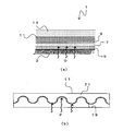
- FIG. 2 is a view showing the multilayer tape 17
- FIG. 2 (a) is a perspective view
- FIG. 2 (b) is a sectional view taken along arrow A of FIG. 2 (a). is there.
- the multilayer tape 17 is composed of a metal layer 19 and a resin coating portion 21.
- the metal layer 19 is sandwiched by the resin coating portion 21.
- the metal layer 19 is thin on the film and easy to process, and may be any material that is excellent in corrosion resistance.
- stainless steel, aluminum, clad steel clad with a material having good corrosion resistance on the outer surface can be used.
- the metal layer 19 has a thickness of, for example, about 0.05 mm, and the entire multilayer tape 17 may have, for example, about 0.2 to 0.3 mm.
- the resin-coated portion 21 is a member made of resin, and can prevent the metal layer 19 from being bent, torn, or wrinkled when the shielding layer 7 is constructed.
- the material of the resin coating portion 21 will be described later.
- the metal layer 19 has a wave shape in cross section.
- a metal layer 19 may be extrusion coated with resin on a corrugated metal film, or may be placed in a corresponding mold to integrate the resin by injection.
- the resin member and the metal film, each having a corresponding corrugated shape, which are separately formed, may be integrated by a known technique such as adhesion or pressure bonding.
- a metal layer can also be formed by vapor deposition etc. in the resin member in which the surface was previously formed in the waveform.
- the metal layer 19 has a wave shape having a peak and a valley, but the peak of the peak (or valley) is referred to as a crest 23. That is, in the cross-sectional example shown in FIG. 2 (b), there are five wave crests 23 on the peak side (upper side).
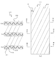
- FIG. 3 (a) is a plan view of the multilayer tape 17
- FIG. 3 (b) is a cross-sectional view taken along the line BB of FIG. 3 (a)
- FIG. 3 (c) is a cross-sectional view of FIG.
- FIG. 3D is a cross-sectional view taken along line C
- FIG. 3D is a cross-sectional view taken along line DD of FIG. 3A.
- the dotted line in the figure represents the position of the crest 23.
- the crest 23 is continuously formed at a predetermined angle with respect to the longitudinal direction of the multilayer tape 17. That is, in the example of FIG. 3A, the crest 23 is formed obliquely at an angle K with respect to the longitudinal direction of the multilayer tape 17.
- the wave shape differs depending on the cross-sectional position.
- the crest 23 at the left end of FIG. 3B is continuously shifted rightward in the drawing as it goes to FIG. 3C and FIG. It is formed.
- FIG.4 (a) is a figure which shows the method of spirally winding the multilayer tape 17 around the outer periphery of the resin layer 5, and FIG.4 (b) is the E section enlarged view of Fig.4 (a).
- the multilayer tape 17 is wound in a spiral (in the direction of arrow F in the figure), for example, as shown in FIG. 4 (a).
- the multilayer tape 17 is supplied and wound in a subsequent process.
- FIG. 5 is an axial sectional view showing a state in which the multilayer tape 17 is wound around the outer periphery of the resin layer 5.
- the multilayer tape 17 has a slight gap on the outer periphery of the resin layer 5 so that the widthwise end portions of the multilayer tape 17 do not overlap each other (do not overlap).
- the multilayer tape 17 may be wound around the upper layer (outer layer) in the same manner by shifting the winding position so as to cover the gap of the lower layer (inner layer) multilayer tape 17 around the outer periphery thereof.
- the multilayer tape 17 may be wrapped and wound so that the widthwise end portions of the multilayer tape 17 overlap each other.
- the multilayer tape 17 can be wound without any gap in the shielding layer regardless of the method of FIG.
- integration of the multilayer tape 17 and the resin layer can use any known means such as adhesion and fusion.
- the material of the resin coating portion 21 is not particularly limited, but may be a rubber material (for example, ethylene rubber, ethylene propylene rubber, silicone rubber, urethane rubber, butyl rubber, etc.). By doing this, the coefficient of friction between the resin layer 5 and the resin-coated portion 21 (the multilayer tape 17) is increased. For this reason, the resin layer 5 and the multilayer tape 17 do not adhere closely and do not shift.
- a rubber material for example, ethylene rubber, ethylene propylene rubber, silicone rubber, urethane rubber, butyl rubber, etc.
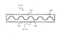
- the resin-coated portion 21 may have a plurality of layers. That is, in the multilayer tape 17a shown in FIG. 6, the resin-coated portion 21 is provided with a resin layer having excellent adhesion to the metal layer 19 in the inner layer, and the rubber portion 21a is formed only with the outer layer by a rubber material. It is also good.
- the axial direction of the flexible tube H and the circumferential direction G of the flexible tube are perpendicular.
- an angle between the circumferential direction G of the flexible tube and the winding direction I of the multilayer tape 17 is J.
- the angle between the longitudinal direction I of the multilayer tape 17 and the crest 23 is K.
- the winding direction I of the multilayer tape 17 coincides with the longitudinal direction of the multilayer tape 17.
- the angle J between the winding direction I of the multilayer tape 17 and the circumferential direction G of the flexible tube, and the angle between the longitudinal direction I of the multilayer tape 17 and the crest 23 should be approximately the same.
- the direction in which the wave crest 23 is formed substantially matches the circumferential direction G of the flexible tube. That is, the winding angle (J) of the multilayer tape 17 is set in advance, and by using the multilayer tape 17 having a crest portion inclined at an angle (K) corresponding to this in the plan view, The stretching direction can be made to substantially coincide with the circumferential direction of the fluid transport flexible tube.
- an angle (J) between the winding direction I and the circumferential direction G of the flexible tube and an angle (K) between the longitudinal direction I of the multilayer tape 17 and the crest 23 cause a slight deviation.
- the outer diameter of the interlocking tube is D
- the axial deviation per winding rotation when the tape is not completely parallel to the circumferential direction is expressed as D ⁇ ⁇ ⁇ tan (J ⁇ K).
- the outer diameter D of the interlock tube is 150 ⁇
- JK is 5 °
- tan 5 ° 0.087, which causes about 41 mm displacement in the winding direction of the tape
- the half The shift per rotation is about 20 mm. Therefore, preferably, the deviation of the angle is 5 ° or less. Further, it is more preferable because the amount of displacement for setting the displacement angle to 2.5 ° is about half of the above.
- FIG. 7 is a view showing another embodiment showing a forming process when longitudinally winding the multilayer tape 17 around the interlock tube 3 in which the resin layer 5 is formed.
- the multilayer tape 17 may be wound longitudinally, as shown in FIG. 7 (a).
- the multilayer tape 17 is sent to the interlock pipe 3 so that the longitudinal direction of the multilayer tape 17 is substantially the same as the axial direction of the interlock pipe 3.
- both sides of the multilayer tape 17 are bent in a U-shape so as to wrap the entire interlock tube 3 (resin layer 5).
- the interlock tube 3 (resin layer 5) is encased by the multilayer tape 17. That is, both end portions of the multilayer tape 17 are wrapped around the outer peripheral portion of the resin layer 5, and the resin layer 5 is wrapped with the multilayer tape 17. That is, the wrap portion 25 is formed along the axial direction of the interlock tube 3. As described above, the multilayer tape 17 may be longitudinally wound around the resin layer 5 to form the shielding layer 7.
- FIG. 8 is a view corresponding to FIG. 4, and FIG. 8 (a) is a view showing a state in which the multilayer tape 17 is longitudinally wound around the outer periphery of the resin layer 5, and FIG. 8 (b) is a view It is an enlarged view corresponding to b).
- the wrap part 25 is formed so that it may be extended in the axial direction (in the figure arrow L direction) of a flexible tube.
- the axial direction H of the flexible tube and the circumferential direction G of the flexible tube are perpendicular.
- the longitudinal direction I of the multilayer tape 17 and the axial direction H of the flexible tube coincide with each other. Therefore, assuming that the angle between the circumferential direction G of the flexible tube and the axial direction H of the flexible tube is J, J is approximately 90 degrees. Further, as described above, the angle K between the longitudinal direction I of the multilayer tape 17 and the crest 23 is also 90 °.
- the angle J (90 °) of the circumferential direction G of the flexible tube with respect to the winding direction I of the multilayer tape 17, the longitudinal direction I of the multilayer tape 17, and the crest 23 can be made to substantially coincide with the circumferential direction of the fluid transport flexible tube by making the angle formed substantially coincide with K (90 °).
- FIG. 9 is a view showing another multilayer tape 17b.
- FIG. 9 (a) is a perspective view of the multilayer tape 17b (a resin-coated portion 21 perspective view), and
- FIG. 9 (b) is a schematic plan view of the metal layer 19. It is.
- a multilayer tape 17b as shown in FIG. 9 may be used.
- the multilayer tape 17b has substantially the same configuration as the multilayer tape 17, but the form of the metal layer 19 is different.
- the crests 23 are continuously formed. That is, as shown in FIG. 3, the multilayer tape 17 has a wave shape in one direction, and the cross section in the direction along the crest 23 does not have a wave shape.
- the multilayer tape 17b has a corrugated shape in two different directions (S direction and T direction in FIG. 9B). Therefore, the peaks 27 and the valleys 29 (wave crests) are formed in a lattice.
- the sectional view taken along the line RR of FIG. 9 (b) is similar to that of the multilayer tape 17 (FIG. 2 (b)).
- a resin may be extrusion-coated on a metal film which has been embossed as shown in FIG. 9, or it is installed in a corresponding mold and the resin is integrated by injection.
- the resin member and the metal film, each having a corresponding uneven shape formed separately may be integrated by a known technique such as adhesion or pressure bonding.
- a metal layer can also be formed by vapor deposition to the resin member in which the surface was previously formed in the embossing shape.
- Such a multilayer tape 17b is wound around the outer periphery of the resin layer 5 by any of the methods shown in FIG. 4 or FIG. 7 to form the shielding layer 7.
- the winding direction of the multilayer tape 17b may be matched with the parallel direction (for example, the S direction or the T direction in FIG. 9B) of the crests as described above.
- the multilayer tape 17b can be deformed in any direction. Therefore, sufficient flexibility can be obtained without completely matching the winding angle and the parallel direction of the crests (S direction or T direction in FIG. 9 (b)).
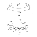
- FIG. 10 is a view showing a state in which the flexible tube 1 is deformed.
- FIG. 10A when the flexible tube 1 is bent and deformed (in the direction of the arrow M in the figure), the flexible tube 1 is subjected to tensile deformation on the bending outer peripheral side (N portion in the figure).
- FIG.10 (b) is a schematic diagram which shows the state of the multilayer tape 17 in N part of FIG. 10 (a).
- FIG.10 (b) is a figure which shows the state in which the multilayer tape 17 was helically wound, for example.
- the multilayer tape 17 wound around the portion also undergoes tensile deformation in the width direction and tries to follow the bending of the flexible tube 1 ( Arrow Q direction in the figure).
- the resin-coated portion 21 can easily follow and deform due to the elastic deformability of the resin.
- the metal layer 19 has a wave shape
- the deformation can be easily followed by the expansion and contraction of the wave.
- the crest 23 is formed to extend in the circumferential direction of the flexible tube 1, the direction of expansion and contraction due to the wave shape corresponds to the axial direction of the flexible tube 1. Therefore, the multilayer tape 17 (the shielding layer 7) can be easily deformed following the bending deformation of the flexible tube 1. That is, the winding of the multilayer tape 17 having the metal layer 19 does not hinder the flexibility (deformation) of the flexible tube 1.
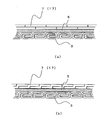
- FIG. 11 is a view showing a cross section of the flexible tube 1.
- FIG. 11 (a) is a cross sectional view in the axial direction
- FIG. 11 (b) is an enlarged view of the multilayer tape 17 constituting the shielding layer 7.
- a fluid such as oil or gas is flowing in the interlock pipe 3.
- the oil, gas and the like may contain hydrogen sulfide which is a corrosive gas, carbon dioxide or carbon dioxide in a supercritical state.
- the resin layer 5 usually provided on the outer peripheral portion of the interlock pipe 3 is in contact with the fluid. Further, the flow of the corrosive gas from the inside of the interlock pipe 3 in the circumferential direction (the direction of the arrow O in the drawing) may pass through the resin layer 5.
- the shielding layer 7 is provided on the outer peripheral surface of the resin layer. Therefore, as shown in FIG. 11 (b), the shielding layer 7 reliably shields the corrosive gas contained in the fluid by the metal layer 19 inside (in the direction of the arrow P in the drawing). Therefore, the reinforcing layers (the internal pressure resistant layer 9 and the axial force reinforcing layer 11) are not deteriorated by the corrosive gas.
- the shielding layer 7 is provided on the outer periphery of the resin layer 5, fluid transportation does not occur that the reinforcing layer is deteriorated by the fluid flowing inside.
- a flexible tube can be obtained.
- the shielding layer 7 is formed of the multilayer tape 17 in which the metal layer 19 is sandwiched by the resin coating portion 21, the flow of the corrosive gas from the interlock tube 3 side in the circumferential direction of the pipe is caused by the metal layer 19. The shielding is ensured and the reinforcing layer does not deteriorate.
- the shielding layer 7 can be reliably constructed without the metal layer 19 being broken or bent at the time of construction of the shielding layer 7. Furthermore, since the metal layer 19 does not contact the interlock tube 3 directly, the interlock tube 3 is not damaged at the time of manufacture.
- the multilayer tape 17 (metal layer 19) can be easily stretched and deformed in the corrugated direction in a state in which the multilayer tape 17 is wound. It is.
- the wave-like crest 23 of the metal layer 19 is formed at a predetermined angle with respect to the longitudinal direction of the multilayer tape 17, and the longitudinal direction of the multilayer tape 17 and the crest 23 in the wave-like shape of the metal layer 19
- the stretching direction of the crest 23 in the state in which the multilayer tape 17 is wound is the flexible tube 1 It can be made to correspond substantially with the circumferential direction of. Therefore, the multilayer tape 17 (metal layer 19) can easily follow the deformation direction of the flexible tube 1 at the time of bending, and high flexibility can be secured.
- the metal layer 19 in an embossed shape, a wave shape is formed in any two different directions. For this reason, the deformation can be followed in any direction, and the productivity of the multilayer tape is also excellent. Further, by forming the metal layer 19 in a wave shape, when the flexible tube is bent, the metal layer 19 can easily follow the deformation, and local stress concentration can be alleviated. Therefore, local excessive stress is not applied to the metal layer 19. Therefore, long-term repeated bending fatigue characteristics can be improved, and a flexible tube excellent in long-term reliability can be obtained.
- FIG. 12 is a view showing another embodiment of the shape of the metal layer 19 in the cross section of the multilayer tape.
- the shape of the metal layer 19 in the cross section of the multilayer tape is not limited to the example described above.
- the wave shape is formed on only a part of the metal layer 19 It may be done. Even in this case, the wave crest portion 23 is formed at a predetermined angle with respect to the longitudinal direction of the multilayer tape 30, so that the same effect as that of the multilayer tape 17 can be obtained.
- the wave shape may be a rectangular wave.
- the wave shape may be a triangular wave. Even in this case, the wave crest portion 23 is formed at a predetermined angle with respect to the longitudinal direction of the multilayer tape, so that the same effect as the multilayer tape 17 can be obtained.
- the wave shape is not limited to these embodiments, as long as it can be expanded and contracted.
- such various wave shapes may be formed in one direction (similar to the multilayer tape 17) or may be formed in two directions (similar to the multilayer tape 17b).
- the resin layer 5 may be formed on the outer peripheral side of the shielding layer 7. Even in this case, since hydrogen sulfide and the like are shielded by the shielding layer 7, it is possible to prevent hydrogen sulfide and the like from invading the reinforcing layer.
- the resin layers 5 a and 5 b may be formed on both sides (inner and outer circumferences) of the shielding layer 7. Even in this case, since hydrogen sulfide and the like are shielded by the shielding layer 7, it is possible to prevent hydrogen sulfide and the like from invading the reinforcing layer. That is, the resin layer may be formed on at least one of the inner peripheral side or the outer peripheral side of the shielding layer 7.
- a resin as a resin of the resin coating portion of the multilayer tape constituting the shielding layer 7 The melting point is lower than the melting point of the resin forming the layer 5 (5b), and one having compatibility with the resin forming the resin layer 5 can be used.
- the resin coating portion 21 may be nylon 12 and the resin layer 5 (5b) may be nylon 11.
- the resin-coated portion 21 (or the surface thereof) may be made of a rubber material.
- the water blocking layer 31 may be formed between the reinforcing layer (seat floor layer 15 d) and the protective layer 13.
- the water blocking layer 31 has the same configuration as the blocking layer 7. That is, the multilayer films 17, 17a and 17b are wound around the outer periphery of the reinforcing layer (seat bed layer 15d) in the same manner as shown in FIG. 4 or FIG. Further, the protective layer 13 is extrusion coated on the outer peripheral portion of the water blocking layer 31.
- the melting point of the resin-coated portion of the multilayer film constituting the water blocking layer 31 is lower than the melting point of the resin forming the protective layer 13, and the resin constituting the resin-coated portion and the resin forming the protective layer 13 And may be compatible with each other.
- the resin-coated portion and the protective layer 13 are compatible and the melting point of the resin-coated portion is lower than the melting point of the protective layer 13, when the resin of the protective layer 13 is extruded, the protective layer 13 and the multilayer tape Are easy to integrate with each other. For this reason, when the protective layer 13 is formed, displacement or the like does not occur between the water blocking layer 31 and the protective layer 13.
- the resin-coated portion may be nylon 12 and the protective layer 13 may be nylon 11.
- the resin-coated portion may be low density polyethylene (LDPE), and the protective layer 13 may be high density polyethylene (HDPE).
- LDPE low density polyethylene
- HDPE high density polyethylene
- the surface of) the resin-coated portion can also be formed of a rubber member (for example, ethylene rubber, ethylene propylene rubber, silicone rubber, urethane rubber, butyl rubber, etc.).
- a rubber member for example, ethylene rubber, ethylene propylene rubber, silicone rubber, urethane rubber, butyl rubber, etc.
- the flexible tube 1c thus configured is usually used by being submerged or floating in the sea. Therefore, the protective layer 13 always contacts with seawater. Since the protective layer 13 is made of resin, it has a certain degree of waterproofness, but the resin itself has a slight water absorption. For this reason, a little seawater component permeates also in the protective layer 13. In particular, high water pressure is applied to the seabed, and there is a large possibility that seawater components may permeate into the protective layer 13 when used for a long time.
- the metal reinforcing layer is located on the inner peripheral portion of the protective layer 13, the reinforcing layer is deteriorated due to corrosion, and there is a possibility that the flexible tube itself may be damaged.
- the water blocking layer 31 is provided on the inner peripheral surface of the protective layer 13. Therefore, the seawater component can be prevented from reaching the reinforcing layer inside the water blocking layer 31. That is, the reinforcing layer is not deteriorated by the seawater component by the water blocking layer 31.
Landscapes
- Engineering & Computer Science (AREA)
- General Engineering & Computer Science (AREA)
- Mechanical Engineering (AREA)
- Rigid Pipes And Flexible Pipes (AREA)
- Laminated Bodies (AREA)
Abstract
Description
また、金属層19を波形状とすることで、可撓管を曲げた際、金属層19が容易に変形に追従可能で、局所的な応力集中を緩和できる。このため、金属層19に局所的な過剰な応力が付与されることがない。したがって、長期的な繰り返し曲げ疲労特性を向上させることができ、長期信頼性に優れる可撓管を得ることができる。
3………インターロック管
5………樹脂層
7………遮蔽層
9………耐内圧補強層
11………軸力補強層
13………保護層
15a、15b、15c、15d………座床層
17、17a、17b、30、40、50………複層テープ
19………金属層
21………樹脂被覆部
21a………ゴム部
23………波頂部
25………ラップ部
27………山部
29………谷部
31………遮水層
Claims (12)
- 可撓性を有する管体と、
前記管体の外周側に設けられた遮蔽層と、
前記遮蔽層の外周側に設けられた補強層と、
前記補強層の外周側に設けられた保護層と、
を少なくとも具備し、
前記遮蔽層と前記管体との間、および/または、前記遮蔽層と前記補強層との間には、さらに樹脂層が形成され、
前記遮蔽層は、樹脂で金属層を挟み込んだ複層テープにより形成され、
前記金属層は、前記複層テープの断面において、少なくとも一部が波形状であることを特徴とする流体輸送用可撓管。 - 前記補強層と前記保護層との間に、さらに遮水層が形成され、
前記遮水層は、断面において少なくとも一部が波形状である金属層を樹脂で挟み込んだ複層テープにより形成されることを特徴とする請求項1記載の流体輸送用可撓管。 - 前記複層テープの平面において、前記金属層の波形状における波頂部が、前記複層テープの長手方向に対して、所定の角度で形成されていることを特徴とする請求項1または請求項2に記載の流体輸送用可撓管。
- 前記金属層の波形状は、前記複層テープの平面において、異なる2方向に向けて形成され、波形状の山部または谷部が格子状に形成されることを特徴とする請求項1記載の流体輸送用可撓管。
- 前記複層テープの長手方向と前記金属層の波形状における波頂部の形成方向とのなす角度は、前記流体輸送用可撓管の周方向に対する前記複層テープの巻きつけ角度と略一致し、前記複層テープが巻きつけられた状態で、前記波頂部の形成方向が前記流体輸送用可撓管の周方向と略一致することを特徴とする請求項3記載の流体輸送用可撓管。
- 前記複層テープの樹脂部は、前記樹脂層と相溶性を有し、前記樹脂層よりも低融点の樹脂製であることを特徴とする請求項1記載の流体輸送用可撓管。
- 前記複層テープの少なくとも表面は、ゴム材料で構成され、前記ゴム材料が前記樹脂層と密着することを特徴とする請求項1記載の流体輸送用可撓管。
- 前記複層テープは、幅方向の端部同士が互いにラップしないように前記流体輸送用可撓管に対して螺旋状に巻きつけられ、内層側の前記複層テープ同士の隙間を覆うように、前記複層テープを2層以上巻きつけることを特徴とする請求項1記載の流体輸送用可撓管。
- 前記複層テープは、前記複層テープの幅方向端部が互いにラップするように前記流体輸送用可撓管に対して、螺旋状に巻きつけられることを特徴とする請求項1記載の流体輸送用可撓管。
- 前記複層テープの長手方向が前記流体輸送用可撓管の軸方向と略一致し、前記複層テープの幅方向が前記流体輸送用可撓管の周方向となるように巻きつけられ、前記複層テープのラップ部が、前記流体輸送用可撓管の軸方向に延伸することを特徴とする請求項1記載の流体輸送用可撓管。
- 可撓性を有する管体を管軸方向に送り、前記管体の外周側に遮蔽層を形成し、前記遮蔽層の外周側に補強層を形成し、前記補強層の外周側に保護層を押出被覆し、前記遮蔽層と管体との間、および/または、前記遮蔽層と前記補強層との間には、さらに樹脂層が押出被覆される流体輸送用可撓管の製造方法であって、
前記遮蔽層は、樹脂で金属層を挟み込んだ複層テープにより形成され、前記金属層は、前記複層テープの断面において、少なくとも一部が波形状であり、
前記複層テープの平面において、前記金属層の波形状における波頂部の形成方向が、前記複層テープの長手方向に対して、所定の角度で形成されており、
前記複層テープの長手方向と前記金属層の波形状における波頂部の形成方向とのなす角度を、前記流体輸送用可撓管の周方向に対する前記複層テープの巻きつけ角度と略一致させて、前記波頂部の延伸方向が前記流体輸送用可撓管の周方向と略一致するように前記複層テープを巻きつけることで前記遮蔽層を形成することを特徴とする流体輸送用可撓管の製造方法。 - 前記金属層の波形状は、前記複層テープの平面において、異なる2方向に向けて形成され、波形状の山部または谷部が格子状に形成されることを特徴とする請求項11記載の流体輸送用可撓管の製造方法。
Priority Applications (2)
| Application Number | Priority Date | Filing Date | Title |
|---|---|---|---|
| JP2012501729A JP5656971B2 (ja) | 2010-02-26 | 2011-02-09 | 流体輸送用可撓管および流体輸送用可撓管の製造方法 |
| BR112012021434A BR112012021434A2 (pt) | 2010-02-26 | 2011-02-09 | tubo flexível para transporte de fluido, e, método para produzir um tubo flexível para transporte de fluido. |
Applications Claiming Priority (2)
| Application Number | Priority Date | Filing Date | Title |
|---|---|---|---|
| JP2010041348 | 2010-02-26 | ||
| JP2010-041348 | 2010-02-26 |
Publications (1)
| Publication Number | Publication Date |
|---|---|
| WO2011105215A1 true WO2011105215A1 (ja) | 2011-09-01 |
Family
ID=44506630
Family Applications (1)
| Application Number | Title | Priority Date | Filing Date |
|---|---|---|---|
| PCT/JP2011/052745 Ceased WO2011105215A1 (ja) | 2010-02-26 | 2011-02-09 | 流体輸送用可撓管および流体輸送用可撓管の製造方法 |
Country Status (3)
| Country | Link |
|---|---|
| JP (1) | JP5656971B2 (ja) |
| BR (1) | BR112012021434A2 (ja) |
| WO (1) | WO2011105215A1 (ja) |
Cited By (1)
| Publication number | Priority date | Publication date | Assignee | Title |
|---|---|---|---|---|
| WO2014040624A1 (en) * | 2012-09-13 | 2014-03-20 | Statoil Petroleum As | Flexible pipe arrangement and method for manufacture thereof |
Citations (7)
| Publication number | Priority date | Publication date | Assignee | Title |
|---|---|---|---|---|
| JPS6388390A (ja) * | 1986-09-29 | 1988-04-19 | 古河電気工業株式会社 | 可撓性流体輸送管 |
| JPH06286014A (ja) * | 1993-03-31 | 1994-10-11 | Sekiyu Kodan | 可撓性流体輸送管の製造方法 |
| JPH07156285A (ja) * | 1993-12-10 | 1995-06-20 | Sekiyu Kodan | 可撓性流体輸送管 |
| JPH0989175A (ja) * | 1995-09-28 | 1997-03-31 | Toyo Tire & Rubber Co Ltd | 埋設可撓継手およびその製造方法 |
| JP2595776Y2 (ja) * | 1993-12-28 | 1999-06-02 | 古河電気工業株式会社 | 不燃被覆導管 |
| US20040060610A1 (en) * | 2001-02-22 | 2004-04-01 | Espinasse Philippe Francois | Flexible duct with shrinkage-proof film |
| WO2009119296A1 (ja) * | 2008-03-28 | 2009-10-01 | 古河電気工業株式会社 | 極低温流体輸送用可撓管および管内の流体の漏洩検知構造 |
Family Cites Families (1)
| Publication number | Priority date | Publication date | Assignee | Title |
|---|---|---|---|---|
| US4006A (en) * | 1845-04-22 | Improvement in self-adjusting platens for cotton and other presses |
-
2011
- 2011-02-09 BR BR112012021434A patent/BR112012021434A2/pt not_active Application Discontinuation
- 2011-02-09 JP JP2012501729A patent/JP5656971B2/ja active Active
- 2011-02-09 WO PCT/JP2011/052745 patent/WO2011105215A1/ja not_active Ceased
Patent Citations (7)
| Publication number | Priority date | Publication date | Assignee | Title |
|---|---|---|---|---|
| JPS6388390A (ja) * | 1986-09-29 | 1988-04-19 | 古河電気工業株式会社 | 可撓性流体輸送管 |
| JPH06286014A (ja) * | 1993-03-31 | 1994-10-11 | Sekiyu Kodan | 可撓性流体輸送管の製造方法 |
| JPH07156285A (ja) * | 1993-12-10 | 1995-06-20 | Sekiyu Kodan | 可撓性流体輸送管 |
| JP2595776Y2 (ja) * | 1993-12-28 | 1999-06-02 | 古河電気工業株式会社 | 不燃被覆導管 |
| JPH0989175A (ja) * | 1995-09-28 | 1997-03-31 | Toyo Tire & Rubber Co Ltd | 埋設可撓継手およびその製造方法 |
| US20040060610A1 (en) * | 2001-02-22 | 2004-04-01 | Espinasse Philippe Francois | Flexible duct with shrinkage-proof film |
| WO2009119296A1 (ja) * | 2008-03-28 | 2009-10-01 | 古河電気工業株式会社 | 極低温流体輸送用可撓管および管内の流体の漏洩検知構造 |
Cited By (1)
| Publication number | Priority date | Publication date | Assignee | Title |
|---|---|---|---|---|
| WO2014040624A1 (en) * | 2012-09-13 | 2014-03-20 | Statoil Petroleum As | Flexible pipe arrangement and method for manufacture thereof |
Also Published As
| Publication number | Publication date |
|---|---|
| JP5656971B2 (ja) | 2015-01-21 |
| BR112012021434A2 (pt) | 2016-05-31 |
| JPWO2011105215A1 (ja) | 2013-06-20 |
Similar Documents
| Publication | Publication Date | Title |
|---|---|---|
| EP2494247B1 (en) | A flexible pipe and a method of producing a flexible pipe | |
| AU2017384001B2 (en) | Petroleum fluid-conveying flexible pipe comprising a barrier against diffusion | |
| US10890276B2 (en) | Metal strip winding continuous reinforced thermoplastic composite pipe | |
| JPH0151717B2 (ja) | ||
| US20120273080A1 (en) | Flexible pipe and a method of producing a flexible pipe | |
| US20040060610A1 (en) | Flexible duct with shrinkage-proof film | |
| MY158401A (en) | Flexible pipe having pressure armour layer and components thereof | |
| JP5777971B2 (ja) | 流体輸送用可撓管および流体輸送用可撓管の製造方法 | |
| JP5255477B2 (ja) | 流体輸送用可撓管の製造方法 | |
| EP3255327B1 (en) | Flexible pipe and related manufacturing method | |
| JP5656971B2 (ja) | 流体輸送用可撓管および流体輸送用可撓管の製造方法 | |
| JP5705827B2 (ja) | 流体輸送用可撓管および流体輸送用可撓管の製造方法 | |
| EP4551854A2 (en) | Permeation-barrier and method of manufacture | |
| CN110805757A (zh) | 一种新型环肋钢带增强柔性复合管 | |
| JP5936305B2 (ja) | 流体輸送用可撓管、腐食性ガスの抜き取り方法、流体輸送システム | |
| GB2535923A (en) | Flexible tubular pipe with resistant retaining layer | |
| CN115614561A (zh) | 一种耐高温非粘结挠性复合管线及制造方法 | |
| AU2019408425B2 (en) | Flexible pipe for conveying a fluid in a submarine environment, and associated method | |
| CN223924122U (zh) | 复合管道 | |
| CN208886161U (zh) | 一种金属带缠绕连续增强热塑性塑料复合管 | |
| CN119630915A (zh) | 渗透阻挡和制造方法 | |
| BR112021012105B1 (pt) | Tubo flexível para transportar um fluido em um ambiente submarino e método de fabricação de um tubo flexível para transportar um fluido em um ambiente submarino |
Legal Events
| Date | Code | Title | Description |
|---|---|---|---|
| 121 | Ep: the epo has been informed by wipo that ep was designated in this application |
Ref document number: 11747179 Country of ref document: EP Kind code of ref document: A1 |
|
| WWE | Wipo information: entry into national phase |
Ref document number: 2012501729 Country of ref document: JP |
|
| NENP | Non-entry into the national phase |
Ref country code: DE |
|
| 122 | Ep: pct application non-entry in european phase |
Ref document number: 11747179 Country of ref document: EP Kind code of ref document: A1 |
|
| REG | Reference to national code |
Ref country code: BR Ref legal event code: B01A Ref document number: 112012021434 Country of ref document: BR |
|
| ENP | Entry into the national phase |
Ref document number: 112012021434 Country of ref document: BR Kind code of ref document: A2 Effective date: 20120824 |