WO2011105039A1 - チタン材料、このチタン材料を構成部材に含む転動装置、及びチタン材料の製造方法 - Google Patents
チタン材料、このチタン材料を構成部材に含む転動装置、及びチタン材料の製造方法 Download PDFInfo
- Publication number
- WO2011105039A1 WO2011105039A1 PCT/JP2011/000946 JP2011000946W WO2011105039A1 WO 2011105039 A1 WO2011105039 A1 WO 2011105039A1 JP 2011000946 W JP2011000946 W JP 2011000946W WO 2011105039 A1 WO2011105039 A1 WO 2011105039A1
- Authority
- WO
- WIPO (PCT)
- Prior art keywords
- phase
- titanium material
- rolling
- aging
- electron
- Prior art date
- Legal status (The legal status is an assumption and is not a legal conclusion. Google has not performed a legal analysis and makes no representation as to the accuracy of the status listed.)
- Ceased
Links
Images











Classifications
-
- C—CHEMISTRY; METALLURGY
- C22—METALLURGY; FERROUS OR NON-FERROUS ALLOYS; TREATMENT OF ALLOYS OR NON-FERROUS METALS
- C22C—ALLOYS
- C22C14/00—Alloys based on titanium
-
- C—CHEMISTRY; METALLURGY
- C22—METALLURGY; FERROUS OR NON-FERROUS ALLOYS; TREATMENT OF ALLOYS OR NON-FERROUS METALS
- C22F—CHANGING THE PHYSICAL STRUCTURE OF NON-FERROUS METALS AND NON-FERROUS ALLOYS
- C22F1/00—Changing the physical structure of non-ferrous metals or alloys by heat treatment or by hot or cold working
- C22F1/16—Changing the physical structure of non-ferrous metals or alloys by heat treatment or by hot or cold working of other metals or alloys based thereon
- C22F1/18—High-melting or refractory metals or alloys based thereon
- C22F1/183—High-melting or refractory metals or alloys based thereon of titanium or alloys based thereon
-
- F—MECHANICAL ENGINEERING; LIGHTING; HEATING; WEAPONS; BLASTING
- F16—ENGINEERING ELEMENTS AND UNITS; GENERAL MEASURES FOR PRODUCING AND MAINTAINING EFFECTIVE FUNCTIONING OF MACHINES OR INSTALLATIONS; THERMAL INSULATION IN GENERAL
- F16C—SHAFTS; FLEXIBLE SHAFTS; ELEMENTS OR CRANKSHAFT MECHANISMS; ROTARY BODIES OTHER THAN GEARING ELEMENTS; BEARINGS
- F16C33/00—Parts of bearings; Special methods for making bearings or parts thereof
- F16C33/30—Parts of ball or roller bearings
- F16C33/32—Balls
-
- F—MECHANICAL ENGINEERING; LIGHTING; HEATING; WEAPONS; BLASTING
- F16—ENGINEERING ELEMENTS AND UNITS; GENERAL MEASURES FOR PRODUCING AND MAINTAINING EFFECTIVE FUNCTIONING OF MACHINES OR INSTALLATIONS; THERMAL INSULATION IN GENERAL
- F16C—SHAFTS; FLEXIBLE SHAFTS; ELEMENTS OR CRANKSHAFT MECHANISMS; ROTARY BODIES OTHER THAN GEARING ELEMENTS; BEARINGS
- F16C33/00—Parts of bearings; Special methods for making bearings or parts thereof
- F16C33/30—Parts of ball or roller bearings
- F16C33/34—Rollers; Needles
-
- F—MECHANICAL ENGINEERING; LIGHTING; HEATING; WEAPONS; BLASTING
- F16—ENGINEERING ELEMENTS AND UNITS; GENERAL MEASURES FOR PRODUCING AND MAINTAINING EFFECTIVE FUNCTIONING OF MACHINES OR INSTALLATIONS; THERMAL INSULATION IN GENERAL
- F16C—SHAFTS; FLEXIBLE SHAFTS; ELEMENTS OR CRANKSHAFT MECHANISMS; ROTARY BODIES OTHER THAN GEARING ELEMENTS; BEARINGS
- F16C33/00—Parts of bearings; Special methods for making bearings or parts thereof
- F16C33/30—Parts of ball or roller bearings
- F16C33/58—Raceways; Race rings
- F16C33/62—Selection of substances
-
- F—MECHANICAL ENGINEERING; LIGHTING; HEATING; WEAPONS; BLASTING
- F16—ENGINEERING ELEMENTS AND UNITS; GENERAL MEASURES FOR PRODUCING AND MAINTAINING EFFECTIVE FUNCTIONING OF MACHINES OR INSTALLATIONS; THERMAL INSULATION IN GENERAL
- F16C—SHAFTS; FLEXIBLE SHAFTS; ELEMENTS OR CRANKSHAFT MECHANISMS; ROTARY BODIES OTHER THAN GEARING ELEMENTS; BEARINGS
- F16C19/00—Bearings with rolling contact, for exclusively rotary movement
- F16C19/22—Bearings with rolling contact, for exclusively rotary movement with bearing rollers essentially of the same size in one or more circular rows, e.g. needle bearings
- F16C19/34—Bearings with rolling contact, for exclusively rotary movement with bearing rollers essentially of the same size in one or more circular rows, e.g. needle bearings for both radial and axial load
- F16C19/36—Bearings with rolling contact, for exclusively rotary movement with bearing rollers essentially of the same size in one or more circular rows, e.g. needle bearings for both radial and axial load with a single row of rollers
- F16C19/361—Bearings with rolling contact, for exclusively rotary movement with bearing rollers essentially of the same size in one or more circular rows, e.g. needle bearings for both radial and axial load with a single row of rollers with cylindrical rollers
- F16C19/362—Bearings with rolling contact, for exclusively rotary movement with bearing rollers essentially of the same size in one or more circular rows, e.g. needle bearings for both radial and axial load with a single row of rollers with cylindrical rollers the rollers being crossed within the single row
-
- F—MECHANICAL ENGINEERING; LIGHTING; HEATING; WEAPONS; BLASTING
- F16—ENGINEERING ELEMENTS AND UNITS; GENERAL MEASURES FOR PRODUCING AND MAINTAINING EFFECTIVE FUNCTIONING OF MACHINES OR INSTALLATIONS; THERMAL INSULATION IN GENERAL
- F16C—SHAFTS; FLEXIBLE SHAFTS; ELEMENTS OR CRANKSHAFT MECHANISMS; ROTARY BODIES OTHER THAN GEARING ELEMENTS; BEARINGS
- F16C29/00—Bearings for parts moving only linearly
- F16C29/04—Ball or roller bearings
- F16C29/06—Ball or roller bearings in which the rolling bodies circulate partly without carrying load
- F16C29/063—Ball or roller bearings in which the rolling bodies circulate partly without carrying load with a bearing body, e.g. a carriage or part thereof, provided between the legs of a U-shaped guide rail or track
-
- F—MECHANICAL ENGINEERING; LIGHTING; HEATING; WEAPONS; BLASTING
- F16—ENGINEERING ELEMENTS AND UNITS; GENERAL MEASURES FOR PRODUCING AND MAINTAINING EFFECTIVE FUNCTIONING OF MACHINES OR INSTALLATIONS; THERMAL INSULATION IN GENERAL
- F16C—SHAFTS; FLEXIBLE SHAFTS; ELEMENTS OR CRANKSHAFT MECHANISMS; ROTARY BODIES OTHER THAN GEARING ELEMENTS; BEARINGS
- F16C29/00—Bearings for parts moving only linearly
- F16C29/04—Ball or roller bearings
- F16C29/06—Ball or roller bearings in which the rolling bodies circulate partly without carrying load
- F16C29/0633—Ball or roller bearings in which the rolling bodies circulate partly without carrying load with a bearing body defining a U-shaped carriage, i.e. surrounding a guide rail or track on three sides
- F16C29/0635—Ball or roller bearings in which the rolling bodies circulate partly without carrying load with a bearing body defining a U-shaped carriage, i.e. surrounding a guide rail or track on three sides whereby the return paths are provided as bores in a main body of the U-shaped carriage, e.g. the main body of the U-shaped carriage is a single part with end caps provided at each end
- F16C29/0638—Ball or roller bearings in which the rolling bodies circulate partly without carrying load with a bearing body defining a U-shaped carriage, i.e. surrounding a guide rail or track on three sides whereby the return paths are provided as bores in a main body of the U-shaped carriage, e.g. the main body of the U-shaped carriage is a single part with end caps provided at each end with balls
- F16C29/0642—Ball or roller bearings in which the rolling bodies circulate partly without carrying load with a bearing body defining a U-shaped carriage, i.e. surrounding a guide rail or track on three sides whereby the return paths are provided as bores in a main body of the U-shaped carriage, e.g. the main body of the U-shaped carriage is a single part with end caps provided at each end with balls with four rows of balls
-
- F—MECHANICAL ENGINEERING; LIGHTING; HEATING; WEAPONS; BLASTING
- F16—ENGINEERING ELEMENTS AND UNITS; GENERAL MEASURES FOR PRODUCING AND MAINTAINING EFFECTIVE FUNCTIONING OF MACHINES OR INSTALLATIONS; THERMAL INSULATION IN GENERAL
- F16C—SHAFTS; FLEXIBLE SHAFTS; ELEMENTS OR CRANKSHAFT MECHANISMS; ROTARY BODIES OTHER THAN GEARING ELEMENTS; BEARINGS
- F16C29/00—Bearings for parts moving only linearly
- F16C29/04—Ball or roller bearings
- F16C29/06—Ball or roller bearings in which the rolling bodies circulate partly without carrying load
- F16C29/068—Ball or roller bearings in which the rolling bodies circulate partly without carrying load with the bearing body fully encircling the guide rail or track
- F16C29/0692—Ball or roller bearings in which the rolling bodies circulate partly without carrying load with the bearing body fully encircling the guide rail or track the bearing body encircles a guide rail or track of non-circular cross-section, e.g. with grooves or protrusions, i.e. the linear bearing is suited to transmit torque
- F16C29/0695—Ball or roller bearings in which the rolling bodies circulate partly without carrying load with the bearing body fully encircling the guide rail or track the bearing body encircles a guide rail or track of non-circular cross-section, e.g. with grooves or protrusions, i.e. the linear bearing is suited to transmit torque with balls
-
- F—MECHANICAL ENGINEERING; LIGHTING; HEATING; WEAPONS; BLASTING
- F16—ENGINEERING ELEMENTS AND UNITS; GENERAL MEASURES FOR PRODUCING AND MAINTAINING EFFECTIVE FUNCTIONING OF MACHINES OR INSTALLATIONS; THERMAL INSULATION IN GENERAL
- F16H—GEARING
- F16H25/00—Gearings comprising primarily only cams, cam-followers and screw-and-nut mechanisms
- F16H25/18—Gearings comprising primarily only cams, cam-followers and screw-and-nut mechanisms for conveying or interconverting oscillating or reciprocating motions
- F16H25/20—Screw mechanisms
- F16H25/22—Screw mechanisms with balls, rollers, or similar members between the co-operating parts; Elements essential to the use of such members
- F16H25/2204—Screw mechanisms with balls, rollers, or similar members between the co-operating parts; Elements essential to the use of such members with balls
- F16H25/2214—Screw mechanisms with balls, rollers, or similar members between the co-operating parts; Elements essential to the use of such members with balls with elements for guiding the circulating balls
-
- F—MECHANICAL ENGINEERING; LIGHTING; HEATING; WEAPONS; BLASTING
- F16—ENGINEERING ELEMENTS AND UNITS; GENERAL MEASURES FOR PRODUCING AND MAINTAINING EFFECTIVE FUNCTIONING OF MACHINES OR INSTALLATIONS; THERMAL INSULATION IN GENERAL
- F16H—GEARING
- F16H25/00—Gearings comprising primarily only cams, cam-followers and screw-and-nut mechanisms
- F16H25/18—Gearings comprising primarily only cams, cam-followers and screw-and-nut mechanisms for conveying or interconverting oscillating or reciprocating motions
- F16H25/20—Screw mechanisms
- F16H25/22—Screw mechanisms with balls, rollers, or similar members between the co-operating parts; Elements essential to the use of such members
- F16H25/2247—Screw mechanisms with balls, rollers, or similar members between the co-operating parts; Elements essential to the use of such members with rollers
Definitions
- the present invention relates to a titanium material, a rolling device including the titanium material as a constituent member, and a method for manufacturing the titanium material.
- titanium materials are generally classified into pure titanium, ⁇ -type titanium alloy, ⁇ + ⁇ -type titanium alloy, and ⁇ -type titanium alloy.
- pure titanium is a dense hexagonal crystal ( ⁇ phase) at room temperature, but undergoes an allotropic transformation (also referred to as a phase transformation) to a body-centered cubic crystal ( ⁇ phase) at about 885 ° C.
- ⁇ phase dense hexagonal crystal
- ⁇ phase transformation an allotropic transformation
- ⁇ phase body-centered cubic crystal
- an ⁇ -type titanium alloy is generally called ⁇ -type titanium alloy and an ⁇ - ⁇ type titanium alloy is one having two phases of ⁇ -phase and ⁇ -phase at room temperature.
- an alloy that can be converted into a ⁇ single phase purely by quenching from a temperature equal to or higher than the ⁇ transformation point is called a ⁇ -type titanium alloy.
- the ⁇ -type titanium alloy is an excellent material having both high strength, light weight, and corrosion resistance, so its use is widespread.
- biomaterials such as artificial bones, accessories such as eyeglass frames, sports such as golf clubs, etc. The field of use is expanding to supplies.
- the ⁇ -phase titanium alloy is unstable in the ⁇ -type titanium alloy, it causes martensitic transformation by rapid cooling, or a metastable phase called ⁇ -phase precipitates due to rapid cooling or aging, causing hardening and embrittlement.
- the ⁇ phase is a phase having a hexagonal crystal structure and coexists on a continuous crystal lattice together with a ⁇ phase having a body-centered cubic crystal structure.
- the manifestation of the ⁇ phase transformation in the titanium alloy affects the physical properties such as strength, toughness and electrical resistance of the titanium alloy.
- the ⁇ phase is relatively soft and the ⁇ phase is very hard, the coexistence structure of these two phases defines the strength of the entire system.
- Hardening and embrittlement of titanium alloy due to precipitation of ⁇ phase occurs when the amount of ⁇ -stabilizing element is small with respect to Ti, which is the base material element. It has been conventionally known that the ⁇ phase that causes hardening and embrittlement can be suppressed by adjusting (see, for example, Patent Document 1 below).
- the present invention has been made in view of the various problems existing in the above-described prior art.
- the purpose of the present invention is based on the results of elucidation of a new phase transformation mechanism in a titanium alloy found by the inventors. It is to provide a titanium material that has not been present in Japan and a technology for applying this titanium material to a rolling device.
- the titanium material according to the present invention has a new phase in which diffraction spots are present at positions deviated from the imaginary line connecting the approximate centers of the diffraction spots of adjacent matrix phases on the electron diffraction pattern obtained by electron microscopy. It is characterized by.
- titanium material according to the present invention can be used as a rolling sliding member in which relative rolling contact or sliding contact occurs with a counterpart member.
- an inner member having a raceway surface on the outer surface
- an outer member having a raceway surface facing the raceway surface of the inner member and disposed on the outer side of the inner member, and the both raceway surfaces
- a rolling device provided so as to be freely rollable, wherein at least one of the inner member, the outer member, and the rolling member is made of the titanium material according to the present invention. Can do.
- the method for producing a titanium material according to the present invention is a method for producing a titanium material used as a rolling sliding member in which relative rolling contact or sliding contact occurs with a counterpart member, which is performed by electron microscopy.
- the Vickers hardness Hv of a titanium material having a new phase in which diffraction spots exist at positions deviated from the imaginary line connecting the approximate centers of the diffraction spots of adjacent matrix phases is 400 or more.
- an aging treatment is performed at a treatment temperature of 300 to 500 ° C. and an aging time of 40 hours or more.
- a titanium material that has not existed in the past and a technique for applying this titanium material to a rolling device. Can be provided.
- FIG. 1 is a diagram for explaining the precipitation form of the ⁇ phase in the Ti-20Mo alloy.
- the fractional diagram (a) in FIG. 1 makes an electron beam incident in parallel to the direction of the ⁇ phase (101) plane.
- the electron diffraction pattern when it was made to show is shown, and the fraction (b) in a figure is a mimetic diagram for explaining fraction (a).
- FIG. 2 is a diagram for explaining the precipitation form of a new phase in a Ti-20Mo alloy.
- the fractional diagram (a) in FIG. 2 makes an electron beam incident parallel to the direction of the ⁇ phase (101) plane.
- FIG. 3 is a graph showing data obtained by this experiment.
- FIG. 4 is a diagram showing plot data to which reference numeral 1-1 is given in FIG. 3.
- a fraction (a) in the figure shows an electron diffraction pattern, and a fraction (b) shows a fraction (a It is a schematic diagram for demonstrating.
- FIG. 5 is a diagram showing plot data to which reference numeral 1-2 is given in FIG. 3.
- a fraction (a) in the figure shows an electron diffraction pattern, and a fraction (b) shows a fraction (a It is a schematic diagram for demonstrating.
- FIG. 4 is a diagram showing plot data to which reference numeral 1-1 is given in FIG. 3.
- a fraction (a) in the figure shows an electron diffraction pattern, and a fraction (b) shows a fraction (a It is a schematic diagram for demonstrating.
- FIG. 5 is a diagram showing plot data to which reference numeral 1-2 is given in FIG. 3.
- a fraction (a) in the figure shows an electron
- FIG. 6 is a diagram showing plot data to which reference numeral 2-1 is given in FIG. 3.
- a fraction (a) in the figure shows an electron diffraction pattern
- a fraction (b) shows a fraction (a It is a schematic diagram for demonstrating.
- FIG. 7 is a diagram showing plot data to which reference numerals 2 to 7 are assigned in FIG. 3.
- a fraction (a) in the figure shows an electron diffraction pattern
- a fraction (b) shows a fraction (a It is a schematic diagram for demonstrating.
- FIG. 8 is a diagram showing plot data to which reference numeral 3-2 is given in FIG. 3.
- a fraction (a) in the figure shows an electron diffraction pattern
- a fraction (b) shows a fraction (a It is a schematic diagram for demonstrating.
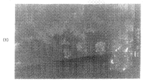
- FIG. 9 is a diagram showing a dark-field image of a new phase created by detecting the diffraction spots indicated by reference numeral 1 in the electron diffraction pattern shown in the partial diagram (a) of FIG.
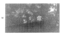
- FIG. 10 is a diagram showing a dark-field image of a new phase created by detecting diffraction spots indicated by reference numeral 2 in the electron diffraction pattern shown in the partial diagram (a) of FIG.
- FIG. 11 is a diagram showing a dark-field image of a new phase created by detecting the diffraction spots indicated by reference numeral 3 in the electron diffraction pattern shown in the partial diagram (a) of FIG.
- FIG. 10 is a diagram showing a dark-field image of a new phase created by detecting the diffraction spots indicated by reference numeral 2 in the electron diffraction pattern shown in the partial diagram (a) of FIG.
- FIG. 11 is a diagram showing a dark-field image of a new phase created by detecting the diffraction spots indicated by
- FIG. 12 is a diagram showing a dark-field image of a new phase created by detecting diffraction spots indicated by reference numeral 4 in the electron diffraction pattern shown in the partial diagram (a) of FIG.
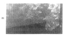
- FIG. 13 is a diagram showing an ⁇ -phase dark field image created by detecting a diffraction spot indicated by reference numeral 5 in the electron diffraction pattern shown in FIG. 8A.
- FIG. 14 is a diagram showing an ⁇ -phase dark field image created by detecting the diffraction spots indicated by reference numeral 6 in the electron diffraction pattern shown in FIG. 8A.
- FIG. 15 is a diagram showing an ⁇ -phase dark field image created by detecting the diffraction spots indicated by reference numeral 7 in the electron diffraction pattern shown in FIG.
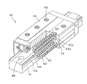
- FIG. 16A is an external perspective view illustrating one embodiment of a linear guide device according to this embodiment configured by a rolling sliding member made of a titanium material.
- FIG. 16B is a cross-sectional view for explaining an infinite circuit provided in the linear guide device shown in FIG. 16A.
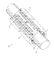
- FIG. 17 is a diagram illustrating a case where the rolling device according to this embodiment is configured as a ball screw device.
- FIG. 18 is a diagram illustrating a case where the rolling device according to this embodiment is configured as a spline device.
- FIG. 19A is a partially longitudinal perspective view illustrating an example of a case where the rolling device according to this embodiment is configured as a rotary bearing device.
- FIG. 19B is a view showing a longitudinal section of the rotary bearing device shown in FIG.
- FIG. 20 is an external perspective view illustrating one mode when the rolling device according to this embodiment is configured as a sliding screw device.
- FIG. 21 is a diagram for explaining various application examples of the present invention, and is an external perspective partial sectional view showing a rolling device of a type in which a linear motion guide and a ball screw are combined to form an integral structure. .
- new phase a new structure-undetermined phase that has not been known in the past in research for elucidating the ⁇ -phase transformation mechanism.
- new phase a transmission electron microscope (Transmission Electron Microscope) in order to obtain electronic knowledge about the ⁇ phase transformation.
- Electron Energy-Loss (Microscopy, TEM) TEM-EELS (hereinafter simply referred to as “electron microscopy”) combined with Spectroscopy (EELS) to collect data for quantitative evaluation of changes in the electronic state density of the parent phase and ⁇ phase as the transformation progresses
- TEM-EELS Electron Energy-Loss
- EELS Spectroscopy
- FIG. 1 and FIG. 2 are shown to explain the difference between the newly discovered new phase and the ⁇ phase.
- FIG. 1 is a diagram for explaining the precipitation form of the ⁇ phase in the Ti-20Mo alloy.
- the fractional diagram (a) in the figure shows that the electron beam is parallel to the direction of the ⁇ phase (101) plane.
- the electron diffraction pattern when it is made to enter is shown
- the fraction figure (b) in a figure is a schematic diagram for demonstrating a fraction figure (a).
- FIG. 2 is a diagram for explaining the precipitation form of the new phase in the Ti-20Mo alloy.
- the fractional diagram (a) in the figure shows that the electron beam is parallel to the direction of the ⁇ phase (101) plane.
- the electron diffraction pattern when it is made to enter is shown
- the fraction figure (b) in a figure is a schematic diagram for demonstrating a fraction figure (a).
- spots with large intensities located at the four corners of the electron diffraction pattern indicate spots of the ⁇ phase 11 that is the parent phase.
- the small spots in FIG. 1 indicate the ⁇ phase 12
- the conventionally known diffraction spots of the ⁇ phase 12 are approximately the center of the diffraction spots of the ⁇ phase 11 diagonally adjacent on the electron diffraction pattern. It is known that it appears at a position that overlaps the line of the virtual line I to be connected, and appears at a position that is one third and two thirds of the length of the line segment of the virtual line I.
- the small spots in FIG. 2 indicate the new phase 22 newly discovered this time.
- the new phase 22 has been confirmed to appear at a position deviating from the virtual line II connecting the approximate centers of the diffraction spots of the ⁇ phase 11 diagonally adjacent to each other on the electron diffraction pattern.
- the new phase 22 had almost the same hardness as the ⁇ phase 12 and excellent ductility.
- the inventors can precipitate the new phase 22 under suitable conditions while eliminating the ⁇ phase 12, the inventors will solve the problem of embrittlement that the ⁇ phase 12 has, while having a new high hardness.
- this new titanium material can be applied to a rolling sliding member that requires high reliability. It is possible to provide a rolling device having a suitable performance that is not present.
- the composition is Ti-15V-3Cr-3Sn-3Al, the density is 4.76 g / cm 3 , and the ⁇ transformation point is 760 ° C.
- the thickness W of an experimental sample two types, 0.6 mm and 1.5 mm, were prepared according to aging conditions.
- FIG. 3 is a graph showing data obtained by this experiment, with the aging time [hrs] on the horizontal axis and the Vickers hardness [Hv] on the vertical axis.
- Table 1 shown below shows the experimental conditions of this experiment, and summarizes the experimental conditions and experimental results for each sample used in this experiment. Note that the experimental conditions and experimental results shown in Table 1 are denoted by reference numerals 1-1, 1-2, 2-1, 2-2, 2-3, 2-4, 2-5, 2 in FIG. The plot data to which ⁇ 6, 2-7, 3-1, 3-2, and 4-1 are assigned are shown.
- Experiment No. 1 is an aging treatment of only one stage at an aging temperature of 300 ° C.
- the first aging treatment is performed at an aging temperature of 300 ° C.
- the second aging treatment is performed at an aging temperature of 400 ° C. or 500 ° C.
- Experiment No. 1 is an aging treatment of only one stage at an aging temperature of 300 ° C.
- the first aging treatment is performed at an aging temperature of 300 ° C.
- the second aging treatment is performed at an aging temperature of 400 ° C. or 500 ° C.
- the Vickers hardness Hv can be secured at least 400 or more, and
- boundary lines III Hv and III hrs indicating the respective lower limit values could be drawn on the graph of FIG.
- a boundary line where the Vickers hardness Hv indicated by the symbol III Hv indicates 400 could be used as the boundary condition.
- a boundary line indicating the aging time 40 hrs indicated by the symbol III hrs could be used as the boundary condition.
- the upper limit value among the values for which plot data was obtained in this experiment can be adopted. That is, the upper limit of the aging time in this experiment is 402 hrs, and the upper limit of the Vickers hardness Hv is 640.
- the upper limit boundary value shown here is only within the range of the present experiment, and from the nature of the present experiment, there is little significance in providing an upper limit.
- KS15-3-3-3 which is a titanium alloy
- the Vickers hardness Hv is 400 or more
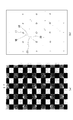
- FIGS. 4 to 8 are diagrams showing plot data to which reference numerals 1-1, 1-2, 2-1, 2-7, and 3-2 are assigned in FIG. 3, respectively.
- FIG. 1A shows an electron diffraction pattern
- FIG. 2B is a schematic diagram for explaining the diagram (a).
- 4A to 8B are electron diffraction patterns when an electron beam is incident in parallel to the direction of the ⁇ phase (101) plane.
- the high-intensity spots indicate the spots of the ⁇ phase 11 that is the parent phase, and the diffraction spots of the ⁇ phase 11 that are diagonally adjacent to each other on the electron diffraction patterns.
- the ⁇ phase 33 appears at the center position of the line segments of the virtual lines IV, V, VI, VII, and VIII connecting the approximate centers of the lines.
- the ⁇ phase does not appear in all the electron diffraction patterns shown in FIGS. 4 to 8, and the virtual line connecting the approximate centers of the diffraction spots of the ⁇ phase 11 diagonally adjacent on the electron diffraction pattern. It can be confirmed that the new phase 22 appears at a position deviated from the lines IV, V, VI, VII, and VIII.
- FIGS. 9 to 15 are diagrams showing dark field images created by detecting the diffraction spots indicated by reference numerals 1 to 7 in the electron diffraction pattern shown in the partial diagram (a) of FIG.
- FIGS. 9 to 12 show dark field images of the new phase 22
- FIGS. 13 to 15 show dark field images of the ⁇ phase 33.
- the conventionally known aspect of the ⁇ phase 33 has a needle-like or columnar crystal grain shape.
- the appearance of the new phase 22 shown in FIG. 9 to FIG. 12 was that many fine crystal grains were precipitated. In this way, by confirming the dark field image, it was possible to confirm the appearance of the new phase 22 that had a distinctly different appearance from the ⁇ phase 33.
- the titanium material and the manufacturing method thereof according to the present invention have been described above.
- the titanium material according to the present invention was found to be a diffraction spot of the matrix adjacent to the diagonal on the electron diffraction pattern obtained by electron microscopy, based on the experiment conducted by the present inventors and analysis of the results. It has been clarified that there are diffraction spots of the new phase 22 at positions deviating from the imaginary line connecting the approximate centers.
- the titanium material according to the present invention had no ⁇ -phase diffraction spots on the electron diffraction pattern obtained by electron microscopy.
- the titanium material according to the present invention can be manufactured by being subjected to an aging treatment at a treatment temperature of 300 to 500 ° C. and an aging time of 40 hours or more, and the Vickers hardness Hv at that time may be 400 or more. It could be confirmed.
- the new phase 22 is a process in which the aging process proceeds and the ⁇ phase 12 disappears mainly after the ⁇ phase 33 and a few ⁇ phases 12 appear in the initial stage of the aging treatment. It was confirmed that it appeared in.
- the titanium material according to the present invention is the one in which the new phase 22 is precipitated while the ⁇ phase 12 disappears, the brittleness is improved while having high hardness.
- the reason why high hardness is obtained even when the ⁇ phase 12 disappears and the new phase 22 appears is that the present inventors are due to the cooperative action of the new phase 22 and the ⁇ phase 33. thinking.
- the titanium material according to the present invention can be suitably used as a rolling sliding member that receives repeated rolling loads and sliding loads. Then, next, the example at the time of applying the titanium material which concerns on this invention to a rolling device is demonstrated.
- rolling device in the present specification includes, for example, rolling bearings used in machine tools and the like, non-lubricated bearings used in vacuum, linear guides and linear guide devices, ball spline devices, ball screw devices, It includes devices with various rolling and sliding operations such as roller screw devices, cross roller rings, slide packs, linear bushings, slide rails and the like.
- FIGS. 16A and 16B are illustrations of linear guide devices.
- the rolling device according to the present embodiment can be configured as a linear guide device as shown in FIGS. 16A and 16B, and by forming such a linear guide device with the titanium material described above, high strength and light weight can be achieved. It is possible to realize an excellent rolling device having the significant characteristics of titanium materials such as property and corrosion resistance.
- FIG. 16A is an external perspective view illustrating an embodiment of the linear guide device according to this embodiment formed of a titanium material.
- FIG. 16B is a cross-sectional view for explaining an infinite circuit provided in the linear guide device shown in FIG. 16A.
- the linear guide device 40 as a rolling device includes a track rail 41 as an inner member, and a track rail 41. And a moving block 43 as an outer member slidably mounted via balls 42... Installed as a number of rolling elements.
- the track rail 41 is a long member whose cross section perpendicular to the longitudinal direction is formed in a substantially rectangular shape, and the surface (upper surface and both side surfaces) of the track rail 41 is a track surface that becomes a track when the balls 42 roll. Are formed over the entire length of the track rail 41.
- the track rail 41 may be formed to extend linearly or may be formed to extend in a curved manner. Further, the number of rolling element rolling surfaces 41a illustrated in FIGS. 16A and 16B is two in total on the left and right, and a total of four is provided. Can be changed.
- the moving block 43 is provided with a loaded rolling element rolling surface 43a as a raceway surface at a position corresponding to each of the rolling element rolling surfaces 41a.
- the rolling element rolling surfaces 41a of the track rail 41 and the loaded rolling element rolling surfaces 43a of the moving block 43 form a load rolling path 52, and a plurality of balls 42 are sandwiched therebetween.
- the moving block 43 includes four unloaded rolling paths 53 extending in parallel with the rolling element rolling surfaces 41a, and a direction change connecting the unloaded rolling paths 53 and the loaded rolling paths 52.
- Paths 55 are provided.
- One infinite circulation path is configured by a combination of one load rolling path 52 and no-load rolling path 53 and a pair of direction changing paths 55 connecting them (see FIG. 16B).
- a plurality of balls 42 are installed in an infinite circulation path composed of a load rolling path 52, a no-load rolling path 53, and a pair of direction changing paths 55, 55 so as to be capable of infinite circulation, thereby moving block 43. Is reciprocally movable relative to the track rail 41.
- the track rail 41 as an inner member
- the moving block 43 as an outer member
- balls 42 installed as a plurality of rolling elements ...
- At least one of the above can be constituted by the above-described titanium material of the present invention.
- all the constituent members can be made of a titanium material, or some of the constituent members can be made of a titanium material. This selection may be performed according to the usage environment of the linear guide device 40 or the like.
- the rolling device according to the present embodiment can be configured as a ball screw device 56 as shown in FIG. 17, for example.
- FIG. 17 is a diagram illustrating a case where the rolling device according to this embodiment is configured as a ball screw device.
- the ball screw device 56 is a device including a screw shaft 57 as an inner member and a nut member 59 as an outer member attached to the screw shaft 57 via a plurality of balls 58 so as to be relatively rotatable. .
- the screw shaft 57 is an inner member in which a rolling element rolling groove 57a as a spiral raceway surface is formed on the outer peripheral surface, while the nut member 59 corresponds to the rolling element rolling groove 57a on the inner peripheral surface. It is an outward member in which a load rolling groove is formed as a spiral raceway surface. As the screw shaft 57 rotates relative to the nut member 59, the nut member 59 can reciprocate relative to the screw shaft 57.
- the screw shaft 57, the nut member 59, the ball 58, and other members constituting the ball screw device 56 can be the titanium material of the present invention.
- the rolling device according to the present embodiment can be configured as, for example, a spline device 60 as shown in FIG.
- FIG. 18 is a diagram illustrating a case where the rolling device according to this embodiment is configured as a spline device.
- the spline device 60 includes a spline shaft 61 as an inward member and a plurality of balls 62 as rolling elements on the spline shaft 61. And a cylindrical outer cylinder 63 as an outer member attached movably.
- rolling element rolling surfaces 61a are formed as raceways for the balls 62 and extending in the axial direction of the spline shaft 21.
- the outer cylinder 63 attached to the spline shaft 61 is formed with a loaded rolling element rolling surface as a raceway surface corresponding to the rolling element rolling surface 61a.
- a plurality of protrusions extending in the direction in which the rolling element rolling surfaces 61a... Extend are formed on these loaded rolling element rolling surfaces.
- a load rolling path is formed between the loaded rolling element rolling surface formed on the outer cylinder 63 and the rolling element rolling surface 61 a formed on the spline shaft 61.
- a no-load return passage is formed in which the balls 62 released from the load move.
- the outer cylinder 63 incorporates a cage 64 for aligning and holding a plurality of balls 62 in a circuit shape.
- a plurality of balls 62 are installed so as to roll freely between the loaded rolling element rolling surface of the outer cylinder 63 and the rolling element rolling surface 61a of the spline shaft 61, and are infinitely circulated through the no-load return passage.
- the outer cylinder 63 can reciprocate relative to the spline shaft 61.
- the spline shaft 61, the outer cylinder 63, the ball 62 and other members constituting the spline device 60 can be made of the titanium material of the present invention.
- the spline device 60 By configuring the spline device 60 in this way, it is possible to realize an excellent spline device 60 having, for example, significant characteristics of a titanium material such as high strength, light weight, and corrosion resistance.
- FIGS. 19A and 19B are a partially longitudinal perspective view illustrating an embodiment in the case where the rolling device according to this embodiment is configured as a rotary bearing device.
- FIG. 19B is a view showing a longitudinal section of the rotary bearing device shown in FIG. 19A.
- the rolling device configured as the rotary bearing device 70 has an inner race 71 (as an inner member or an outer member) having an inner raceway surface 72 having a V-shaped cross section on the outer peripheral surface. And an outer race 73 (as an outer member or an inner member) having an outer raceway surface 74 having a V-shaped cross section on the inner circumferential surface, an inner raceway surface 72 and an outer raceway surface 74, and a substantially rectangular cross section.
- the inner ring 71 and the outer ring 73 perform a relative rotational movement in the circumferential direction by having a plurality of rollers 77 as rolling elements that are cross-arranged between the raceway paths 75.
- the excellent rotary bearing device 70 having the significant characteristics of the titanium material such as high strength, light weight, and corrosion resistance can be obtained. Can be realized.
- the apparatus of the form with which the some rolling element was interposed between the inner member and the outer member was illustrated and demonstrated.
- the scope of application of the present invention which is characterized in that the rolling device is constituted by a titanium material, is not limited to the one using such a rolling element, and the inner member and the outer member can be arranged without using the rolling element.
- the present invention can also be suitably used for an apparatus configured to be in direct contact and capable of relative movement.
- FIG. 20 is an external perspective view illustrating an example of a case where the rolling device according to this embodiment is configured as a sliding screw device.
- a sliding screw device 80 shown in FIG. 20 includes a screw shaft 81 as an inner member in which a screw groove as a spiral raceway surface is formed on the outer peripheral surface, and a helical screw corresponding to the screw groove on the inner peripheral surface.
- a nut member 83 as an outer member in which a nut groove as a raceway surface is formed, so that the nut member 83 is attached to the screw shaft 81 as the screw shaft 81 rotates relative to the nut member 83. It is comprised so that it can reciprocate relatively with respect to it.
- any one or all of the screw shaft 81 and the nut member 83 which are constituent members thereof can be made of the titanium material of the present invention.
- an excellent sliding screw device 80 having, for example, significant characteristics of a titanium material such as high strength, light weight, and corrosion resistance is realized. be able to.
- the present invention can be applied to a rolling device 90 of a type in which a linear motion guide and a ball screw are combined as shown in FIG.
- the screw shaft 91 and the moving block 93 are installed via a plurality of balls 95. It is also possible to configure the moving block 93 as a sliding screw.
- KS15-3-3-3 which is a Ti-15V-3Cr-3Sn-3Al-based titanium alloy
- Types of titanium alloys can be included.
- the present inventors can eliminate the ⁇ phase by aging the Ti-14Mo alloy, Ti-20Mo alloy, SP-700 titanium alloy, etc., under the above-described conditions of the present invention, and newly It has been confirmed that the phase can be precipitated.
Landscapes
- Engineering & Computer Science (AREA)
- General Engineering & Computer Science (AREA)
- Mechanical Engineering (AREA)
- Chemical & Material Sciences (AREA)
- Materials Engineering (AREA)
- Metallurgy (AREA)
- Organic Chemistry (AREA)
- Physics & Mathematics (AREA)
- Thermal Sciences (AREA)
- Crystallography & Structural Chemistry (AREA)
- Rolling Contact Bearings (AREA)
- Bearings For Parts Moving Linearly (AREA)
Abstract
このチタン材料は、電子顕微鏡法によって得られた電子回折図形上で、対角に隣り合う母相11の回折斑点の略中心を結ぶ仮想線上から逸れた位置に新相22の回折斑点が存在するとともに、ω相12の回折斑点が存在しないことを特徴としている。新相22は、時効処理の初期段階において主としてα相33とわずかのω相12が出現した後に、時効処理が進んで前記ω相12が消失する過程で出現したものであり、時効処理は、処理温度300~500℃、時効時間40hrs以上の条件にて実施される。また、このチタン材料は、ビッカース硬さHvが400以上を示す。これにより、相変態を制御してω相を消失させるとともに新相を析出させたチタン材料を得た。そして、このチタン材料は、転動装置に適用することができる。
Description
本発明は、チタン材料、このチタン材料を構成部材に含む転動装置、及びチタン材料の製造方法に関するものである。
チタン材料は、一般に、純チタン、α型チタン合金、α+β型チタン合金、β型チタン合金に大別されることが従来から知られている。このうちの純チタンは、常温で稠密六方晶(α相)であるが、約885℃で体心立方晶(β相)に同素変態(または、相変態ともいう。)する。このような純チタンに合金元素を添加すると、元素の種類や添加量によりβ変態点が変化し、α相及びβ相と呼ばれる2相領域が出現する。そして、合金化しても、常温においてα単相のものがα型チタン合金、α相とβ相の2相が存在するものがα+β型チタン合金と一般に呼ばれている。また、β変態点以上の温度から焼き入れで純安定的にβ単相となり得る合金が、β型チタン合金と呼ばれている。
以上のようなチタン材料は、鉄鋼材料に比べて比強度(=引張強さ/比重)に優れることから、古くから航空、軍事、宇宙、海洋探査等の分野で使用されてきた。特に、β型チタン合金は、高強度、軽量性、耐食性を併せ持つ優れた材料であるため、その用途は広く、最近では、人工骨等の生体材料、眼鏡フレームなどの装身具、ゴルフクラブ等のスポーツ用品などにも使用分野が広がりつつある。
ただし、β型チタン合金には、β相が不安定なために、急冷によってマルテンサイト変態を起こしたり、急冷や時効によってω相と呼ばれる準安定相が析出し、硬化と脆化を起こしたりするといった問題が存在していた。ここで、ω相とは、六方晶構造を持つ相であり、体心立方晶構造を持つβ相とともに連続した結晶格子上に共存するものである。チタン合金におけるω相変態の発現は、チタン合金の強度や靭性、電気抵抗等の物理的性質に影響を与えるものである。また、β相は比較的柔らかく、ω相は非常に硬いので、これら2相の共存組織が系全体の強度を規定することとなる。
ω相の析出によるチタン合金の硬化と脆化は、母材元素であるTiに対してβ安定化元素量が少ない場合に起こるが、この問題に対しては、Al等の合金元素の添加量を調整することで、硬化及び脆化の原因となるω相を抑制できることが従来から知られている(例えば、下記特許文献1参照)。
また、ω相が有する非常に硬いという性質に着目し、チタン合金中のω相の析出量(存在率や粒径など)を制御することで、高硬度でありながらも、耐摩耗性といった有意な特性にも優れたチタン材料を転がり摺動部材の構成材料に利用し、チタン合金製の転動装置を得る技術が提案されている(例えば、下記特許文献2参照)。
チタン合金の強度、靭性、電気抵抗等の物理的性質に影響を与えるω相変態の発現については、実用上の問題ばかりでなく変態機構解明の見地からも非常に重要であり、多数の研究がなされている。特に、種々の相変態が実用材料の材質改善や機能開発に広く応用されている現状では、拡散型及び変位型の両変態挙動を呈するω相変態機構の解明は、その信頼性向上や、さらなる応用のためにも必要な問題となっている。
しかしながら、ω相を含む相変態機構について、より本質的な解明は不十分であり、研究の余地が残されていた。また、ω相を含む相変態機構の解明に基づき、従来にはない、より好適な性質を有するとともに実業界にて利用可能なチタン材料を提供することが求められていた。例えば、上掲した特許文献2では、チタン合金中のω相の析出量を制御することで、高硬度のチタン材料を転がり摺動部材の構成材料に利用する技術が提案されているが、ω相変態機構の解明が不十分である現状においては、特許文献2が提案する技術は最適なものとはいえず、脆化を伴うω相を析出させた材料を転動装置という高い信頼性を要求される装置に適用することには、多くの問題が含まれていた。
本発明は、上述した従来技術に存在する種々の問題に鑑みて成されたものであり、その目的は、発明者らが見出したチタン合金における新たな相変態機構の解明結果に基づいて、従来には存在しなかったチタン材料と、このチタン材料を転動装置に適用する技術を提供することにある。
本発明に係るチタン材料は、電子顕微鏡法によって得られた電子回折図形上で、隣り合う母相の回折斑点の略中心を結ぶ仮想線上から逸れた位置に回折斑点が存在する新相を有することを特徴とするものである。
また、上記本発明に係るチタン材料は、相手部材との間で相対的な転がり接触又はすべり接触が生じる転がり摺動部材として用いることができる。
さらに、外面に軌道面を有する内方部材と、前記内方部材の軌道面に対向する軌道面を有して前記内方部材の外側に配置された外方部材と、前記両軌道面間に転動自在に配置された転動体と、を備える転動装置において、前記内方部材、前記外方部材及び前記転動体のうちの少なくとも1つが、本発明に係るチタン材料から成ることとすることができる。
またさらに、本発明に係るチタン材料の製造方法は、相手部材との間で相対的な転がり接触又はすべり接触が生じる転がり摺動部材として用いられるチタン材料の製造方法であって、電子顕微鏡法によって得られた電子回折図形上で、隣り合う母相の回折斑点の略中心を結ぶ仮想線上から逸れた位置に回折斑点が存在する新相を有するチタン材料のビッカース硬さHvが400以上となるように、処理温度300~500℃、時効時間40hrs以上の時効処理を施すことを特徴としている。
本発明によれば、発明者らが見出したチタン合金における新たな相変態機構の解明結果に基づいて、従来には存在しなかったチタン材料と、このチタン材料を転動装置に適用する技術を提供することができる。
(新相の発見)
発明者らは、ω相変態機構を解明するための研究の中で、従来では知られていなかった新たな構造未決定相(以下、「新相」と記す。)を発見するに至った。すなわち、発明者らは、ω相変態についての電子論的知見を得るために、透過電子顕微鏡(Transmission Electron
Microscopy, TEM)に電子エネルギー損失分光法(Electron Energy-Loss
Spectroscopy, EELS)を組み合わせたTEM-EELS(以下、単に「電子顕微鏡法」と記す。)を用いて、変態進行に伴う母相とω相の電子状態密度変化を定量的評価するデータの収集を行ったところ、採用した二段時効法の時効過程において、チタン材料の新しい析出形態を観察するに至った。具体的には、従来の学説では、「β-ω-α」の相変態が進行すると考えられていたが、時効条件によっては、新相の出現があることを確認したのである。
発明者らは、ω相変態機構を解明するための研究の中で、従来では知られていなかった新たな構造未決定相(以下、「新相」と記す。)を発見するに至った。すなわち、発明者らは、ω相変態についての電子論的知見を得るために、透過電子顕微鏡(Transmission Electron
Microscopy, TEM)に電子エネルギー損失分光法(Electron Energy-Loss
Spectroscopy, EELS)を組み合わせたTEM-EELS(以下、単に「電子顕微鏡法」と記す。)を用いて、変態進行に伴う母相とω相の電子状態密度変化を定量的評価するデータの収集を行ったところ、採用した二段時効法の時効過程において、チタン材料の新しい析出形態を観察するに至った。具体的には、従来の学説では、「β-ω-α」の相変態が進行すると考えられていたが、時効条件によっては、新相の出現があることを確認したのである。
ここで、新たに発見された新相とω相との相違点を説明するために、図1及び図2を示す。なお、図1は、Ti-20Mo合金におけるω相の析出形態を説明するための図であり、特に、図中の分図(a)は、電子線をβ相(101)面の方向に平行に入射させたときの電子回折図形を示しており、図中の分図(b)は、分図(a)を説明するための模式図である。また、図2は、Ti-20Mo合金における新相の析出形態を説明するための図であり、特に、図中の分図(a)は、電子線をβ相(101)面の方向に平行に入射させたときの電子回折図形を示しており、図中の分図(b)は、分図(a)を説明するための模式図である。
図1及び図2において、電子回折図形の四隅に位置する強度の大きな斑点は、母相であるβ相11の斑点を示している。そして、図1中の小さい斑点がω相12を示しており、この従来から知られるω相12の回折斑点は、電子回折図形上で対角に隣り合うβ相11の回折斑点の略中心を結ぶ仮想線Iの線上と重なる位置に現れるとともに、仮想線Iの線分の長さの三分の一と三分の二の長さの位置に出現することが知られている。
一方、図2中の小さい斑点は、今回新たに発見された新相22を示している。この新相22については、電子回折図形上で対角に隣り合うβ相11の回折斑点の略中心を結ぶ仮想線IIの線上から逸れた位置に出現することが確認されている。
また、新相22については、ω相12と比較して硬度がほぼ同程度であり、延性が優れていることが確認された。そこで、発明者らは、ω相12を消失させつつ新相22を好適な条件で析出させることができれば、ω相12が有していた脆化の問題を解消しつつも高い硬度を有する新たなチタン材料を提供できることに着目した。また、このような新たなチタン材料を安定して量産できる技術を確立できれば、高い信頼性が要求される転がり摺動部材にこの新たなチタン材料を適用することができ、さらには、従来にはない好適な性能を有する転動装置を提供することが可能となる。発明者らは、これらの着想に基づく研究を鋭意行った結果、ω相12及び新相22の変態過程を明確にし、新相22を有するチタン材料を安定して量産できる製造条件を見出すことに成功したのである。そこで次に、発明者らが行った実験と、かかる実験によって見出されたω相12を消失させつつ新相22を好適に析出させるための条件について、説明することとする。
(実験内容及び結果)
上述したように、新相22は、二段時効法の時効過程において出現することが確認されていたので、発明者らは、この新相22が出現するとともにω相12が消失し、しかもビッカース硬さHvが少なくとも400以上を確保できる時効処理条件を見出すことを実験の目的とした。この実験において採用された実験試料は、鋼種名KS15-3-3-3として知られる高成形性高強度チタン合金であり、その外郭形状については、例えばドーナツ形を採用することとした。
上述したように、新相22は、二段時効法の時効過程において出現することが確認されていたので、発明者らは、この新相22が出現するとともにω相12が消失し、しかもビッカース硬さHvが少なくとも400以上を確保できる時効処理条件を見出すことを実験の目的とした。この実験において採用された実験試料は、鋼種名KS15-3-3-3として知られる高成形性高強度チタン合金であり、その外郭形状については、例えばドーナツ形を採用することとした。
すなわち、本実験は、上記ドーナツ形からなる外郭形状を有するKS15-3-3-3製の実験試料を用意し、この実験試料に時効処理を行いながら、任意の時効処理時間ごとにおけるビッカース硬さHvを確認するとともに、電子顕微鏡法によって得られる電子回折図形を観察することで、ビッカース硬さHvが少なくとも400以上を確保でき、かつ、ω相12が消失して新相22が析出する時効処理条件を見出すことで行われた。
なお、KS15-3-3-3の物性については、組成がTi-15V-3Cr-3Sn-3Al、密度が4.76g/cm3、β変態点が760℃となっている。また、実験試料の厚みWについては、時効条件に応じて0.6mmと1.5mmの2種類を用意した。
次に、本実験の条件と結果を図3及び表1に示す。ここで、図3は、本実験によって得られたデータを示すグラフ図であり、横軸に時効時間[hrs]が、縦軸にビッカース硬さ[Hv]がとられている。また、以下に示す表1は、本実験の実験条件を示すとともに、本実験で使用された試料ごとの実験条件及び実験結果をまとめたものである。なお、表1にて示される実験条件及び実験結果については、図3中で符号1-1,1-2,2-1,2-2,2-3,2-4,2-5,2-6,2-7,3-1,3-2,4-1が付与されたプロットデータを抜き出して示してある。

今回発明者らが行った実験では、実験No.1~4で示される4回の実験が実施されている。実験No.1及び実験No.2で示された実験は、実験試料の厚みWが0.6mmのものが採用されている。特に、実験No.1は、時効温度300℃で一段のみの時効処理が行われており、一方の実験No.2については、時効温度300℃で一段目の時効処理を行った後に、時効温度400℃又は500℃で二段目の時効処理を行うことが実施されている。また、実験No.3において、時効時間が120hrsまでの時効処理については、実験試料の厚みWが0.6mmのものが採用されており、時効時間が120hrs以降の時効処理については、実験試料の厚みWが1.5mmのものが採用されている。さらに、実験No.4については、実験結果の再現性の有無を確認するために、実験試料の厚みWが1.5mmのものを用いて実験No.3と全く同じ条件にて実験が行われたものである。またさらに、実験No.3及び実験No.4における時効処理は、時効温度300℃にて一段のみの時効処理が行われている。
図3に示された実験No.3のプロットデータからも明らかな通り、実験試料の厚みWが変化したとしても、その変化の前後でのプロットは連続的な曲線を描いており、実験試料の厚みWの変化が実験結果に及ぼす影響は少ないことが確認された。また、実験No.3のプロットデータと実験No.4のプロットデータは非常に近い値を示している。したがって、この結果から、本実験の結果が十分な汎用性を持ち、さらに、十分な再現性を有するものであることが確認できた。これらの結果から、本実験の有効性が確認されたので、続いて実験結果の解析を行った。
すなわち、図3に示されたプロットデータごとの実験試料におけるビッカース硬さHvと、電子顕微鏡法によって得られる電子回折図形を観察することで、ビッカース硬さHvが少なくとも400以上を確保でき、かつ、ω相12が消失して新相22が析出する時効処理条件を確認したところ、図3のグラフ図上にそれぞれの下限値を示す境界線IIIHv,IIIhrsを引くことができた。ビッカース硬さHvの下限値については、符号IIIHvで指示されるビッカース硬さHvが400を示す境界線を境界条件とすることができた。一方、時効時間の下限値については、符号IIIhrsで指示される時効時間40hrsを示す境界線を境界条件とすることができた。
上限値の境界についての考え方としては、本実験にてプロットデータが得られた値のうちの上限値を採用することもできる。すなわち、本実験での時効時間の上限値は402hrsであり、ビッカース硬さHvの上限値は640である。ただし、ここで示された上限境界値については、あくまで本実験の範囲でのものであり、また、本実験の性質から、上限を設けることの意味は少ないであろう。
以上の結果から、チタン合金であるKS15-3-3-3においては、処理温度300~500℃、時効時間40hrs以上の時効処理を施すことによって、ビッカース硬さHvが400以上であり、かつ、ω相12が消失して新相22が析出した新たなチタン材料を得られることが明らかとなった。
なお、ω相12が消失して新相22が析出するメカニズムについては未だ明確にはなっていないが、その現象面での状況は把握することができた。すなわち、上述した発明条件から外れた実験試料を電子顕微鏡法によって観察したところ、時効処理の初期段階において主としてα相とわずかのω相12が出現した後に、時効処理が進むことで前記ω相12が消失して新相22が出現するという現象を確認することができた。また、ω相12と新相22は混在することが確認されており、さらに、ω相12の消失過程において新相22が増加していくことが確認されている。したがって、従来から考えられている「β-ω-α」の順での相変態の進行過程については、「β-ω-新相-α」の順での相変態の進行過程が存在することが、今回の実験で明らかとなった。
また、新相22を確実に出現させるために、実験No.2では二段時効の処理を行ったが、今回の実験によって、二段時効法を用いなくとも、ω相12を消失させて新相22を析出させることが可能であることが明らかとなった(ただし、本発明方法は、二段時効法を含むものである)。
次に、上述した本実験の電子顕微鏡法によって得られた電子回折図形のうちの代表例を、図4~図8に示す。なお、図4~図8は、それぞれ図3において符号1-1,1-2,2-1,2-7,3-2が付与されたプロットデータを示す図であり、各図中の分図(a)は、電子回折図形を示し、分図(b)は、分図(a)を説明するための模式図である。なお、図4~図8における分図(a)の電子回折図形は、電子線をβ相(101)面の方向に平行に入射させたときの電子回折図形を示している。
図4~図8で示される全ての電子回折図形において、強度の大きな斑点が母相であるβ相11の斑点を示しており、電子回折図形上で対角に隣り合うβ相11の回折斑点の略中心を結ぶ仮想線IV,V,VI,VII,VIIIの線分の中央位置にα相33が出現している。そして、図4~図8で示される全ての電子回折図形でω相は出現しておらず、かつ、電子回折図形上で対角に隣り合うβ相11の回折斑点の略中心を結ぶ仮想線IV,V,VI,VII,VIIIの線上から逸れた位置に新相22が出現していることが確認できる。
次に、新相22がどのような様相を呈するかを確認するために、暗視野像を取得した。取得した暗視野像を図9~図15に示す。なお、図9~図15は、図8の分図(a)で示した電子回折図形において、それぞれ符号1~7で示した回折斑点を検出して作成した暗視野像を示す図である。また、図9~図12は、新相22の暗視野像を示し、図13~図15は、α相33の暗視野像を示している。
図13~図15に示されるように、従来から知られるα相33の様相は、針状あるいは柱状の結晶粒形を呈している。一方、図9~図12に示される新相22の様相は、多数の微細な結晶粒が析出したものであった。このように、暗視野像を確認することにより、α相33とは明らかに異なった様相を呈する新相22の様相を確認することができた。
以上、本発明に係るチタン材料とその製造方法について説明を行った。上述したように、本発明者らが行った実験及びその結果解析によって、本発明に係るチタン材料は、電子顕微鏡法によって得られた電子回折図形上で、対角に隣り合う母相の回折斑点の略中心を結ぶ仮想線上から逸れた位置に新相22の回折斑点が存在することが明らかとなった。
また、本発明に係るチタン材料では、電子顕微鏡法によって得られた電子回折図形上で、ω相の回折斑点が存在しないことを確認した。
さらに、本発明に係るチタン材料は、処理温度300~500℃、時効時間40hrs以上の時効処理を施されることで製造可能であり、その際のビッカース硬さHvは、400以上となることが確認できた。
またさらに、本発明に係るチタン材料において、新相22は、時効処理の初期段階において主としてα相33とわずかのω相12が出現した後に、時効処理が進んで前記ω相12が消失する過程で出現したものであることを確認した。
なお、本発明に係るチタン材料は、ω相12を消失させながらも新相22を析出させたものなので、高い硬度を有しながらも脆性が改善されている。また、ω相12が消失して新相22が出現した際にも高い硬度が得られる理由として、本発明者らは、新相22とα相33との協働した作用によるものであると考えている。以上のことから、本発明に係るチタン材料は、繰り返しの転がり負荷や摺動負荷を受けることとなる転がり摺動部材として、好適に用いることが可能である。そこで、次に、本発明に係るチタン材料を転動装置へ適用した場合の事例について、説明を行う。
(転動装置への適用例)
次に、本発明のチタン材料を転がり摺動部材として用いた転動装置の具体的な実施形態について、図面を用いて説明する。なお、以下で例示する転動装置の実施形態は、各請求項に係る発明を限定するものではなく、また、実施形態の中で説明されている特徴の組み合わせの全てが発明の解決手段に必須であるとは限らない。また、本明細書における「転動装置」は、例えば、工作機械などに用いられる転がり軸受全般や真空中で使用される無潤滑軸受、リニアガイドや直線案内装置、ボールスプライン装置、ボールねじ装置、ローラねじ装置、クロスローラリング、スライドパック、リニアブッシュ、スライドレールなどのような、あらゆる転動・摺動動作を伴う装置を含むものである。
次に、本発明のチタン材料を転がり摺動部材として用いた転動装置の具体的な実施形態について、図面を用いて説明する。なお、以下で例示する転動装置の実施形態は、各請求項に係る発明を限定するものではなく、また、実施形態の中で説明されている特徴の組み合わせの全てが発明の解決手段に必須であるとは限らない。また、本明細書における「転動装置」は、例えば、工作機械などに用いられる転がり軸受全般や真空中で使用される無潤滑軸受、リニアガイドや直線案内装置、ボールスプライン装置、ボールねじ装置、ローラねじ装置、クロスローラリング、スライドパック、リニアブッシュ、スライドレールなどのような、あらゆる転動・摺動動作を伴う装置を含むものである。
~リニアガイド装置への適用例~
本実施形態に係る転動装置は、図16A及び図16Bに示すようなリニアガイド装置として構成することが可能であり、かかるリニアガイド装置を上述したチタン材料によって構成することにより、高強度、軽量性、耐食性といったチタン材料が有する有意な特性を併せ持つ優れた転動装置を実現することができる。ここで、図16Aは、チタン材料によって構成される本実施形態に係るリニアガイド装置の一形態を例示する外観斜視図である。また、図16Bは、図16Aで示したリニアガイド装置が備える無限循環路を説明するための断面図である。
本実施形態に係る転動装置は、図16A及び図16Bに示すようなリニアガイド装置として構成することが可能であり、かかるリニアガイド装置を上述したチタン材料によって構成することにより、高強度、軽量性、耐食性といったチタン材料が有する有意な特性を併せ持つ優れた転動装置を実現することができる。ここで、図16Aは、チタン材料によって構成される本実施形態に係るリニアガイド装置の一形態を例示する外観斜視図である。また、図16Bは、図16Aで示したリニアガイド装置が備える無限循環路を説明するための断面図である。
まず、図16A及び図16Bに例示するリニアガイド装置40の構成について説明すると、本実施形態に係る転動装置としてのリニアガイド装置40は、内方部材としての軌道レール41と、軌道レール41に多数の転動体として設置されるボール42…を介してスライド可能に取り付けられた外方部材としての移動ブロック43とを備えている。軌道レール41はその長手方向と直交する断面が概略矩形状に形成された長尺の部材であり、その表面(上面及び両側面)には、ボール42…が転がる際の軌道になる軌道面としての転動体転走面41a…が軌道レール41の全長に渡って形成されている。
ここで軌道レール41は、直線的に伸びるように形成されることもあるし、曲線的に伸びるように形成されることもある。また、図16A及び図16Bにおいて例示する転動体転走面41a…の本数は左右で2条ずつ合計4条設けられているが、その条数はリニアガイド装置40の用途等に応じて任意に変更することができる。
一方、移動ブロック43には、転動体転走面41a…とそれぞれ対応する位置に軌道面としての負荷転動体転走面43a…が設けられている。軌道レール41の転動体転走面41a…と移動ブロック43の負荷転動体転走面43a…とによって負荷転走路52…が形成され、複数のボール42…が挟まれている。さらに、移動ブロック43には、各転動体転走面41a…と平行に伸びる4条の無負荷転走路53…と、各無負荷転走路53…と各負荷転走路52…とを結ぶ方向転換路55…が設けられている。1つの負荷転走路52及び無負荷転走路53と、それらを結ぶ一対の方向転換路55との組み合わせによって、1つの無限循環路が構成される(図16B参照)。
そして、複数のボール42…が、負荷転走路52と無負荷転走路53と一対の方向転換路55,55とから構成される無限循環路に無限循環可能に設置されることにより、移動ブロック43が軌道レール41に対して相対的に往復運動可能となっている。
以上のような構成を備える本実施形態に係るリニアガイド装置40においては、内方部材としての軌道レール41、外方部材としての移動ブロック43、及び、複数の転動体として設置されるボール42…の少なくとも1つを、上述した本発明のチタン材料によって構成することができる。
なお、本実施形態に係るリニアガイド装置40は、全ての構成部材をチタン材料によって構成することもできるし、一部の構成部材をチタン材料によって構成することもできる。この選択は、リニアガイド装置40の使用環境等に応じて行えばよい。
~転動体ねじ装置への適用例~
また、本実施形態に係る転動装置は、例えば、図17において示されるようなボールねじ装置56として構成することが可能である。図17は、本実施形態に係る転動装置をボールねじ装置として構成した場合を例示する図である。かかるボールねじ装置56は、内方部材としてのねじ軸57と、このねじ軸57に複数のボール58を介して相対回転可能に取り付けられる外方部材としてのナット部材59とを備えた装置である。
また、本実施形態に係る転動装置は、例えば、図17において示されるようなボールねじ装置56として構成することが可能である。図17は、本実施形態に係る転動装置をボールねじ装置として構成した場合を例示する図である。かかるボールねじ装置56は、内方部材としてのねじ軸57と、このねじ軸57に複数のボール58を介して相対回転可能に取り付けられる外方部材としてのナット部材59とを備えた装置である。
ねじ軸57は、外周面に螺旋状の軌道面としての転動体転走溝57aが形成される内方部材であり、一方、ナット部材59は、内周面に転動体転走溝57aに対応する螺旋状の軌道面としての負荷転走溝が形成される外方部材である。ねじ軸57のナット部材59に対する相対的な回転運動に伴って、ナット部材59がねじ軸57に対して相対的に往復運動可能となっている。
そして、ボールねじ装置56を構成するねじ軸57やナット部材59、ボール58及びその他の部材を本発明のチタン材料とすることができる。ボールねじ装置56をこのように構成することによって、例えば、高強度、軽量性、耐食性といったチタン材料が有する有意な特性を併せ持つ優れたボールねじ装置56を実現することができる。
~スプライン装置への適用例~
さらに、本実施形態に係る転動装置は、例えば、図18において示されるようなスプライン装置60として構成することが可能である。図18は、本実施形態に係る転動装置をスプライン装置として構成した場合を例示する図である。
さらに、本実施形態に係る転動装置は、例えば、図18において示されるようなスプライン装置60として構成することが可能である。図18は、本実施形態に係る転動装置をスプライン装置として構成した場合を例示する図である。
ここで、図18に示されるスプライン装置60の構成を簡単に説明すると、スプライン装置60は、内方部材としてのスプライン軸61と、そのスプライン軸61に多数の転動体としてのボール62…を介して移動自在に取り付けられた外方部材としての円筒状の外筒63とを有している。スプライン軸61の表面には、ボール62の軌道となり、スプライン軸21の軸線方向に延びる軌道面としての転動体転走面61a…が形成されている。スプライン軸61に取り付けられる外筒63には、転動体転走面61aに対応する軌道面としての負荷転動体転走面が形成される。これらの負荷転動体転走面には、転動体転走面61a…が伸びる方向に伸びる複数条の突起が形成されている。外筒63に形成した負荷転動体転走面とスプライン軸61に形成した転動体転走面61aとの間で負荷転走路が形成される。負荷転走路の隣には、荷重から解放されたボール62…が移動する無負荷戻し通路が形成されている。外筒63には、複数のボール62…をサーキット状に整列・保持する保持器64が組み込まれている。そして、複数のボール62…が、外筒63の負荷転動体転走面とスプライン軸61の転動体転走面61aとの間に転動自在に設置され、無負荷戻し通路を通って無限循環するように設置されることによって、外筒63がスプライン軸61に対して相対的に往復運動可能となっている。
そして、図18において示すスプライン装置60の場合においても、スプライン装置60を構成するスプライン軸61や外筒63、ボール62及びその他の部材を本発明のチタン材料によって構成することが可能である。スプライン装置60をこのように構成することによって、例えば、高強度、軽量性、耐食性といったチタン材料が有する有意な特性を併せ持つ、優れたスプライン装置60を実現することができる。
~回転ベアリング装置への適用例~
またさらに、本実施形態に係る転動装置は、例えば、図19A及び図19Bにおいて示されるような回転ベアリング装置70として構成することが可能である。ここで、図19Aは、本実施形態に係る転動装置を回転ベアリング装置として構成した場合の一形態を例示する部分縦断斜視図である。また、図19Bは、図19Aに示す回転ベアリング装置の縦断面を示す図である。
またさらに、本実施形態に係る転動装置は、例えば、図19A及び図19Bにおいて示されるような回転ベアリング装置70として構成することが可能である。ここで、図19Aは、本実施形態に係る転動装置を回転ベアリング装置として構成した場合の一形態を例示する部分縦断斜視図である。また、図19Bは、図19Aに示す回転ベアリング装置の縦断面を示す図である。
図19A及び図19Bに示すように、回転ベアリング装置70として構成される転動装置は、外周面に断面V字形状の内側軌道面72を有する(内方部材又は外方部材としての)内輪71と、内周面に断面V字形状の外側軌道面74を有する(外方部材又は内方部材としての)外輪73と、内側軌道面72と外側軌道面74とによって形成される断面略矩形状の軌道路75の間に転動可能にクロス配列される複数の転動体としてのローラ77…とを有することにより、内輪71及び外輪73が周方向に相対的な回転運動を行うものである。
このような回転ベアリング装置70を構成する部材を、本発明のチタン材料によって構成することにより、例えば、高強度、軽量性、耐食性といったチタン材料が有する有意な特性を併せ持つ優れた回転ベアリング装置70を実現することができる。
~滑りねじ装置への適用例~
上述した各装置については、内方部材と外方部材の間に複数の転動体が介装された形態の装置を例示して説明した。しかしながら、チタン材料によって転動装置を構成することを特徴とする本発明の適用範囲は、かかる転動体を用いたものには限られず、転動体を介さずに内方部材と外方部材とが直接接触して相対運動可能に構成される装置に対しても好適に用いることが可能である。
上述した各装置については、内方部材と外方部材の間に複数の転動体が介装された形態の装置を例示して説明した。しかしながら、チタン材料によって転動装置を構成することを特徴とする本発明の適用範囲は、かかる転動体を用いたものには限られず、転動体を介さずに内方部材と外方部材とが直接接触して相対運動可能に構成される装置に対しても好適に用いることが可能である。
例えば、図20に示すように、滑りねじ装置80として構成される転動装置に対して、本発明を適用することも可能である。ここで、図20は、本実施形態に係る転動装置を滑りねじ装置として構成した場合の一形態を例示する外観斜視図である。そして、図20に示す滑りねじ装置80は、外周面に螺旋状の軌道面としてのねじ溝が形成される内方部材としてのねじ軸81と、内周面にねじ溝に対応する螺旋状の軌道面としてのナット溝が形成される外方部材としてのナット部材83と、を有することにより、ねじ軸81のナット部材83に対する相対的な回転運動に伴って、ナット部材83がねじ軸81に対して相対的に往復運動することができるように構成されている。
また、図20に示す滑りねじ装置80についても、その構成部材であるねじ軸81及びナット部材83のいずれか一方又は全てを、本発明のチタン材料にて構成することが可能である。このような滑りねじ装置80を構成する部材を、チタン材料によって構成することにより、例えば、高強度、軽量性、耐食性といったチタン材料が有する有意な特性を併せ持つ、優れた滑りねじ装置80を実現することができる。
以上、本発明の好適な実施形態について説明したが、本発明の技術的範囲は上記実施形態に記載の範囲には限定されない。上記実施形態には、多様な変更又は改良を加えることが可能である。
例えば、図21において示されるような、リニアモーションガイドとボールねじが組み合わされて一体構造となっている形式の転動装置90について、本発明を適用することが可能である。なお、図21において示す転動装置90の場合、ねじ軸91と移動ブロック93とは、複数のボール95…を介して設置されているが、複数のボール95…を介さずにねじ軸91と移動ブロック93とが滑りねじとして構成されるようにすることも可能である。
また、本実施形態では、Ti-15V-3Cr-3Sn-3Al系のチタン合金であるKS15-3-3-3を用いて行った実験結果を示したが、本発明のチタン材料にはその他の種類のチタン合金を含むことができる。例えば、本発明者らは、Ti-14Mo合金やTi-20Mo合金、SP-700チタン合金等であっても、上述した本発明条件にて時効処理を行うことで、ω相を消失させて新相を析出させることができることを確認している。
その様な変更又は改良を加えた形態も本発明の技術的範囲に含まれ得ることが、請求の範囲の記載から明らかである。
11 β相、12 ω相、22 新相、33 α相、40 リニアガイド装置、41 軌道レール、41a 転動体転走面、42 ボール、43 移動ブロック、43a 負荷転動体転走面、48,49 ねじ孔、52 負荷転走路、53 無負荷転走路、55 方向転換路、56 ボールねじ装置、57 ねじ軸、57a 転動体転走溝、58 ボール、59 ナット部材、60 スプライン装置、61 スプライン軸、61a 転動体転走面、62 ボール、63 外筒、64 保持器、70 回転ベアリング装置、71 内輪、72 内側軌道面、73 外輪、74 外側軌道面、75 軌道路、77 ローラ、80 滑りねじ装置、81 ねじ軸、83 ナット部材、90 転動装置、91 ねじ軸、93 移動ブロック、95 ボール。
Claims (8)
- 電子顕微鏡法によって得られた電子回折図形上で、隣り合う母相の回折斑点の略中心を結ぶ仮想線上から逸れた位置に回折斑点が存在する新相を有することを特徴とするチタン材料。
- 請求項1に記載のチタン材料において、
電子顕微鏡法によって得られた電子回折図形上で、ω相の回折斑点が存在しないことを特徴とするチタン材料。 - 請求項1又は2に記載のチタン材料において、
処理温度300~500℃、時効時間40hrs以上の時効処理を施されることで、ビッカース硬さHvが400以上であることを特徴とするチタン材料。 - 請求項1~3のいずれか1項に記載のチタン材料において、
前記新相は、時効処理の初期段階において主としてα相とわずかのω相が出現した後に、時効処理が進んで前記ω相が消失する過程で出現したものであることを特徴とするチタン材料。 - 請求項1~4のいずれか1項に記載のチタン材料において、
相手部材との間で相対的な転がり接触又はすべり接触が生じる転がり摺動部材として用いられることを特徴とするチタン材料。 - 外面に軌道面を有する内方部材と、
前記内方部材の軌道面に対向する軌道面を有して前記内方部材の外側に配置された外方部材と、
前記両軌道面間に転動自在に配置された転動体と、
を備える転動装置において、
前記内方部材、前記外方部材及び前記転動体のうちの少なくとも1つが、請求項1~5のいずれか1項に記載のチタン材料から成ることを特徴とする転動装置。 - 相手部材との間で相対的な転がり接触又はすべり接触が生じる転がり摺動部材として用いられるチタン材料の製造方法であって、
電子顕微鏡法によって得られた電子回折図形上で、隣り合う母相の回折斑点の略中心を結ぶ仮想線上から逸れた位置に回折斑点が存在する新相を有するチタン材料のビッカース硬さHvが400以上となるように、処理温度300~500℃、時効時間40hrs以上の時効処理を施すことを特徴とするチタン材料の製造方法。 - 請求項7に記載のチタン材料の製造方法において、
電子顕微鏡法によって得られた電子回折図形上で、ω相の回折斑点が存在しないように、時効処理の初期段階において主としてα相とわずかのω相を出現させた後、時効処理を進めることで前記ω相を消失させて前記新相を出現させる処理を実行することを特徴とするチタン材料の製造方法。
Applications Claiming Priority (2)
| Application Number | Priority Date | Filing Date | Title |
|---|---|---|---|
| JP2010-037949 | 2010-02-23 | ||
| JP2010037949A JP2011174120A (ja) | 2010-02-23 | 2010-02-23 | チタン材料、このチタン材料を構成部材に含む転動装置、及びチタン材料の製造方法 |
Publications (1)
| Publication Number | Publication Date |
|---|---|
| WO2011105039A1 true WO2011105039A1 (ja) | 2011-09-01 |
Family
ID=44506473
Family Applications (1)
| Application Number | Title | Priority Date | Filing Date |
|---|---|---|---|
| PCT/JP2011/000946 Ceased WO2011105039A1 (ja) | 2010-02-23 | 2011-02-21 | チタン材料、このチタン材料を構成部材に含む転動装置、及びチタン材料の製造方法 |
Country Status (3)
| Country | Link |
|---|---|
| JP (1) | JP2011174120A (ja) |
| TW (1) | TWI487899B (ja) |
| WO (1) | WO2011105039A1 (ja) |
Families Citing this family (2)
| Publication number | Priority date | Publication date | Assignee | Title |
|---|---|---|---|---|
| JP5908715B2 (ja) * | 2011-12-27 | 2016-04-26 | Thk株式会社 | 転動装置の製造方法 |
| WO2017018514A1 (ja) * | 2015-07-29 | 2017-02-02 | 新日鐵住金株式会社 | チタン複合材および熱間圧延用チタン材 |
Citations (3)
| Publication number | Priority date | Publication date | Assignee | Title |
|---|---|---|---|---|
| JPS5217307A (en) * | 1975-07-31 | 1977-02-09 | Kobe Steel Ltd | Process for heat treatment of beta-type titanium alloy |
| JPH02258960A (ja) * | 1988-12-26 | 1990-10-19 | Seiko Instr Inc | 鏡面を有するチタン合金の製造方法 |
| JP2003120689A (ja) * | 2001-10-17 | 2003-04-23 | Nsk Ltd | 転動装置 |
Family Cites Families (3)
| Publication number | Priority date | Publication date | Assignee | Title |
|---|---|---|---|---|
| JPH01152250A (ja) * | 1987-12-10 | 1989-06-14 | Nippon Steel Corp | 高硬度値を有するβ型チタン合金の製造方法 |
| JP2003166541A (ja) * | 2001-11-29 | 2003-06-13 | Nsk Ltd | 転動装置 |
| JP4939741B2 (ja) * | 2004-10-15 | 2012-05-30 | 住友金属工業株式会社 | nearβ型チタン合金 |
-
2010
- 2010-02-23 JP JP2010037949A patent/JP2011174120A/ja active Pending
-
2011
- 2011-02-21 WO PCT/JP2011/000946 patent/WO2011105039A1/ja not_active Ceased
- 2011-02-22 TW TW100105731A patent/TWI487899B/zh active
Patent Citations (3)
| Publication number | Priority date | Publication date | Assignee | Title |
|---|---|---|---|---|
| JPS5217307A (en) * | 1975-07-31 | 1977-02-09 | Kobe Steel Ltd | Process for heat treatment of beta-type titanium alloy |
| JPH02258960A (ja) * | 1988-12-26 | 1990-10-19 | Seiko Instr Inc | 鏡面を有するチタン合金の製造方法 |
| JP2003120689A (ja) * | 2001-10-17 | 2003-04-23 | Nsk Ltd | 転動装置 |
Also Published As
| Publication number | Publication date |
|---|---|
| TWI487899B (zh) | 2015-06-11 |
| TW201144797A (en) | 2011-12-16 |
| JP2011174120A (ja) | 2011-09-08 |
Similar Documents
| Publication | Publication Date | Title |
|---|---|---|
| Horita et al. | Microstructures and microhardness of an aluminum alloy and pure copper after processing by high-pressure torsion | |
| Han et al. | Increasing strength and conductivity of Cu alloy through abnormal plastic deformation of an intermetallic compound | |
| Fu et al. | Microstructure and mechanical behavior of a novel Co20Ni20Fe20Al20Ti20 alloy fabricated by mechanical alloying and spark plasma sintering | |
| Ayyagari et al. | Surface degradation mechanisms in precipitation-hardened high-entropy alloys | |
| Edalati et al. | High strength and high uniform ductility in a severely deformed iron alloy by lattice softening and multimodal-structure formation | |
| Zhang et al. | Effect of Ni content and Hf addition on the unlubricated wear performance of Ni-rich NiTi alloys | |
| JP6725235B2 (ja) | 転がり摺動部材及びその製造方法並びに転がり軸受 | |
| Ma et al. | Achieving high strength-ductility synergy in nickel aluminum bronze alloy via a quenching-aging-tempering heat treatment | |
| Zhilyaev et al. | Effect of annealing on wear resistance and electroconductivity of copper processed by high-pressure torsion | |
| Mao et al. | Trifunctional local-range order oxygen structure enhanced strength-ductility and fatigue resistance in large-scale metastable titanium alloy | |
| Zhen-yu et al. | Research on fabricating gradient nanostructure and enhancing wear resistance in aluminum alloy via two-dimensional ultrasonic surface burnishing | |
| Xu et al. | Microstructure, mechanical properties, and corrosion resistance of L21 phase-strengthened laser cladding CrFeNiTixAl1-x high-entropy alloy coatings | |
| Chu et al. | Microstructure and Mechanical Behavior of FeNiCoCr and FeNiCoCrMn High-Entropy Alloys Fabricated by Powder Metallurgy: C. Chu et al. | |
| JP2011174120A (ja) | チタン材料、このチタン材料を構成部材に含む転動装置、及びチタン材料の製造方法 | |
| JP5759410B2 (ja) | 転動装置の製造方法 | |
| Ren et al. | Exceptional strength and antibacterial durability in hierarchically structured Cu-bearing 316L stainless steel through additive manufacturing | |
| Korneva et al. | Microstructure evolution and magnetic properties of hard magnetic FeCr22Co15 alloy subjected to tension combined with torsion | |
| Kim et al. | Mechanism of unique hardening of dental Ag–Pd–Au–Cu alloys in relation with constitutional phases | |
| Lan et al. | Strong yet ductile carbide-strengthened niobium alloy fabricated by laser powder bed fusion | |
| Peng et al. | Achieving high strain hardening and strength in an additively manufactured titanium alloy | |
| Li et al. | Enhanced mechanical properties and structural stability of HF-Modified NITI alloy for advanced bearing materials | |
| DE102017215222A1 (de) | Einsatzhärtbare Edelstahllegierung | |
| JP5908715B2 (ja) | 転動装置の製造方法 | |
| Kilic et al. | Dry sliding wear behaviour and microstructure of the W–Ni–Fe and W–Ni–Cu heavy alloys produced by powder metallurgy technique | |
| Trung et al. | An investigation of the properties of conventional and severe shot peened low alloy steel |
Legal Events
| Date | Code | Title | Description |
|---|---|---|---|
| 121 | Ep: the epo has been informed by wipo that ep was designated in this application |
Ref document number: 11747011 Country of ref document: EP Kind code of ref document: A1 |
|
| NENP | Non-entry into the national phase |
Ref country code: DE |
|
| 122 | Ep: pct application non-entry in european phase |
Ref document number: 11747011 Country of ref document: EP Kind code of ref document: A1 |