WO2011104903A1 - 中空エンジンバルブの製造方法及び中空エンジンバルブ - Google Patents
中空エンジンバルブの製造方法及び中空エンジンバルブ Download PDFInfo
- Publication number
- WO2011104903A1 WO2011104903A1 PCT/JP2010/061934 JP2010061934W WO2011104903A1 WO 2011104903 A1 WO2011104903 A1 WO 2011104903A1 JP 2010061934 W JP2010061934 W JP 2010061934W WO 2011104903 A1 WO2011104903 A1 WO 2011104903A1
- Authority
- WO
- WIPO (PCT)
- Prior art keywords
- valve head
- hollow
- valve
- finished
- semi
- Prior art date
- Legal status (The legal status is an assumption and is not a legal conclusion. Google has not performed a legal analysis and makes no representation as to the accuracy of the status listed.)
- Ceased
Links
Images



Classifications
-
- F—MECHANICAL ENGINEERING; LIGHTING; HEATING; WEAPONS; BLASTING
- F01—MACHINES OR ENGINES IN GENERAL; ENGINE PLANTS IN GENERAL; STEAM ENGINES
- F01L—CYCLICALLY OPERATING VALVES FOR MACHINES OR ENGINES
- F01L3/00—Lift-valve, i.e. cut-off apparatus with closure members having at least a component of their opening and closing motion perpendicular to the closing faces; Parts or accessories thereof
- F01L3/12—Cooling of valves
- F01L3/14—Cooling of valves by means of a liquid or solid coolant, e.g. sodium, in a closed chamber in a valve
-
- B—PERFORMING OPERATIONS; TRANSPORTING
- B21—MECHANICAL METAL-WORKING WITHOUT ESSENTIALLY REMOVING MATERIAL; PUNCHING METAL
- B21D—WORKING OR PROCESSING OF SHEET METAL OR METAL TUBES, RODS OR PROFILES WITHOUT ESSENTIALLY REMOVING MATERIAL; PUNCHING METAL
- B21D41/00—Application of procedures in order to alter the diameter of tube ends
- B21D41/04—Reducing; Closing
- B21D41/045—Closing
-
- B—PERFORMING OPERATIONS; TRANSPORTING
- B21—MECHANICAL METAL-WORKING WITHOUT ESSENTIALLY REMOVING MATERIAL; PUNCHING METAL
- B21J—FORGING; HAMMERING; PRESSING METAL; RIVETING; FORGE FURNACES
- B21J5/00—Methods for forging, hammering, or pressing; Special equipment or accessories therefor
- B21J5/06—Methods for forging, hammering, or pressing; Special equipment or accessories therefor for performing particular operations
- B21J5/08—Upsetting
-
- B—PERFORMING OPERATIONS; TRANSPORTING
- B21—MECHANICAL METAL-WORKING WITHOUT ESSENTIALLY REMOVING MATERIAL; PUNCHING METAL
- B21K—MAKING FORGED OR PRESSED METAL PRODUCTS, e.g. HORSE-SHOES, RIVETS, BOLTS OR WHEELS
- B21K1/00—Making machine elements
- B21K1/20—Making machine elements valve parts
- B21K1/22—Making machine elements valve parts poppet valves, e.g. for internal-combustion engines
-
- B—PERFORMING OPERATIONS; TRANSPORTING
- B21—MECHANICAL METAL-WORKING WITHOUT ESSENTIALLY REMOVING MATERIAL; PUNCHING METAL
- B21K—MAKING FORGED OR PRESSED METAL PRODUCTS, e.g. HORSE-SHOES, RIVETS, BOLTS OR WHEELS
- B21K21/00—Making hollow articles not covered by a single preceding sub-group
- B21K21/12—Shaping end portions of hollow articles
- B21K21/14—Shaping end portions of hollow articles closed or substantially-closed ends, e.g. cartridge bottoms
-
- B—PERFORMING OPERATIONS; TRANSPORTING
- B23—MACHINE TOOLS; METAL-WORKING NOT OTHERWISE PROVIDED FOR
- B23P—METAL-WORKING NOT OTHERWISE PROVIDED FOR; COMBINED OPERATIONS; UNIVERSAL MACHINE TOOLS
- B23P15/00—Making specific metal objects by operations not covered by a single other subclass or a group in this subclass
- B23P15/001—Making specific metal objects by operations not covered by a single other subclass or a group in this subclass valves or valve housings
- B23P15/002—Making specific metal objects by operations not covered by a single other subclass or a group in this subclass valves or valve housings poppet valves
-
- F—MECHANICAL ENGINEERING; LIGHTING; HEATING; WEAPONS; BLASTING
- F01—MACHINES OR ENGINES IN GENERAL; ENGINE PLANTS IN GENERAL; STEAM ENGINES
- F01L—CYCLICALLY OPERATING VALVES FOR MACHINES OR ENGINES
- F01L3/00—Lift-valve, i.e. cut-off apparatus with closure members having at least a component of their opening and closing motion perpendicular to the closing faces; Parts or accessories thereof
- F01L3/20—Shapes or constructions of valve members, not provided for in preceding subgroups of this group
Definitions
- the present invention relates to a manufacturing method for manufacturing a hollow engine valve having a hollow hole therein by using rotary swaging or spinning in the manufacturing process, and a hollow engine valve manufactured by the manufacturing method. is there.
- Patent Document 1 discloses a method of forming a valve head part of a hollow engine valve by cold necking
- Patent Document 2 discloses a method of forming a valve head part of a hollow engine valve by warm necking. Is disclosed.
- the valve head part of a hollow engine valve is formed by hot forging a pipe material or by expanding the tip of a solid round bar by hot forging and drilling a hollow hole at the other end with a drill.
- a solid round bar is first formed to produce a cup-shaped semi-finished product having an enlarged diameter portion at the bottom (first step).
- the semi-finished product has a two-stage process in which the upper part of the diameter-expanded part and the body part are subjected to necking processing in the cold or warm state to form a finished product (second step). It has been attracting attention as a blind spot in the world, where there was no idea of warming necking to mold the valve head part of a hollow engine valve.
- the trunk portion of the valve head portion cannot be made too long by necking. Therefore, in addition to the valve head portion, a separate member such as a hollow shaft portion or a shaft end sealing material is necessary, and welding between the members is also necessary. Since the strength of the welded part is inevitably lowered, the heat resistance and durability are inevitably inferior to those of a hollow engine valve consisting entirely of one member. This is due to the structure of the die to be molded. In the necking process, the workpiece must be finally knocked out of the die. However, if the workpiece becomes too long, this knockout causes technical difficulties.
- the thickness of the barrel part of the semi-finished part of the valve head part is first set too thick, the final required thickness Since the thickness of the barrel portion of the semi-finished product is limited, it is not suitable for manufacturing a valve head portion having a long barrel portion. In other words, it is natural that the thicker body part can be made longer when it becomes a valve head part of a finished product, but it can be squeezed by necking. Since there is a limit to the thickness of the body, it is not suitable for manufacturing a valve head with a long body.
- the third problem is that in necking, if the length of the workpiece becomes too long, the number of cases where buckling occurs during drawing up increases. Also, if the workpiece is long, a large load is applied to the punch and the die, so that the punch is bent and the die is severely damaged. That is, the mold life of the mold is shortened, which is not economical.
- the fourth problem is that when the steel material used is a difficult-to-process material, even when warm forging is used in the process of drawing the semi-finished product of the valve head part to the valve head part of the finished product.
- the number of dies will increase considerably. If the number of dies increases, there will be many intermediate heat treatment steps such as annealing, and it will be impossible to carry out all the steps only by necking, which is impractical.
- SUH38 was a somewhat difficult material to be processed, but could be necked without any problems by the methods described in Patent Documents 1 and 2 below.
- SUH11 and SUH35 which are further difficult to process materials, technical difficulties gradually increase and yield deteriorates, and in SUH3, which is further considered to have poor workability, currently, The method has not been successful.
- a first step is to obtain a cup-shaped semi-finished product having a diameter-enlarged part at the bottom with a bottom when a solid round bar is molded and the open end is on the top. Then, while maintaining the two-step process of the second step, the upper part of the diameter-expanded part and the body part of the semi-finished product are reduced in diameter to form the valve head part of the finished product,
- the semi-finished product can be expanded so that a finished product valve head portion having a trunk portion that can be made into a finished hollow engine valve can be obtained simply by sealing the shaft end (open end).
- the present invention has been made to solve the above-described problems, and provides the means for solving the problems described below.
- ⁇ Solution 1> In the method of manufacturing a hollow engine valve, the hollow hole is formed with an enlarged diameter in the enlarged portion of the valve head portion, and the maximum inner diameter of the hollow hole is larger than the minimum outer diameter of the body portion of the valve head portion.
- There is a first step of manufacturing a semi-finished product of a valve head part from a solid round bar of the material and a second step of making the semi-finished product of the valve head part a finished product head part by cold forging or warm forging.
- the cylindrical body has an enlarged diameter part integral with the body at one end, the cylindrical part has a cylindrical hollow hole, and the enlarged part side is on the lower side, the cylindrical shape
- the hollow hole is a semi-finished product of a valve head part whose upper end is opened and whose lower end is bottomed in the enlarged diameter part
- the semi-finished valve head part is reduced in diameter by the rotary swaging process or by the spinning process in the cold or warm atmosphere. Or, the diameter is reduced by a combination of rotary swaging and spinning, The maximum outer diameter of the enlarged part of the valve head part of the finished product is maintained at the maximum outer diameter of the enlarged part of the semi-finished part of the valve head part.
- the maximum inner diameter is obtained as a valve umbrella part of the finished product in which the inner diameter of the cylindrical hollow hole of the valve umbrella part semi-finished product is maintained as the inner diameter.
- a method for producing a hollow engine valve characterized in that: ⁇ Solution 2> A hollow shaft is obtained by welding a hollow shaft portion to an opening end portion of a finished valve head portion obtained by the method of Solution 1 and further welding a shaft end sealing material to the hollow shaft portion. A method for manufacturing an engine valve.
- ⁇ Solution 3> A method for manufacturing a hollow engine valve, wherein a finished hollow engine valve is obtained by welding a shaft end sealing material to an opening end portion of a finished valve head portion obtained by the method of Solution 1.
- ⁇ Solution 4> A method for manufacturing a hollow engine valve, wherein a finished hollow engine valve is obtained by sealing an open end of a finished valve head portion obtained by the method of Solution 1.
- ⁇ Solution 5> In the method of manufacturing a hollow engine valve, the hollow hole is formed with an enlarged diameter in the enlarged portion of the valve head portion, and the maximum inner diameter of the hollow hole is larger than the minimum outer diameter of the body portion of the valve head portion.
- There is a first step of manufacturing a semi-finished product of a valve head part from a solid round bar of the material and a second step of making the semi-finished product of the valve head part a finished product head part by cold forging or warm forging.
- the cylindrical body has an enlarged diameter part integral with the body at one end, the cylindrical part has a cylindrical hollow hole, and the enlarged part side is on the lower side, the cylindrical shape
- the hollow hole is a semi-finished product of a valve head part whose upper end is opened and whose lower end is bottomed in the enlarged diameter part
- the diameter of the semi-finished valve head part is reduced by combining necking with rotary swaging in a cold or warm atmosphere, or by combining necking with spinning.
- ⁇ Solution 7> A method for manufacturing a hollow engine valve, wherein a finished hollow engine valve is obtained by welding a shaft end sealing material to an opening end portion of a finished valve head portion obtained by the method of Solution 5.
- ⁇ Solution 8> A method for manufacturing a hollow engine valve, wherein a hollow engine valve of a finished product is obtained by sealing an open end of a valve head portion of a finished product obtained by the method of Solution 5.
- ⁇ Solution 9> A hollow engine valve manufactured by the method for manufacturing a hollow engine valve according to any one of Solution 1 to Solution 8.
- the process is divided into two stages, and a cup-shaped semi-finished product having an enlarged diameter portion is manufactured in advance (first step), and then the upper portion of the enlarged diameter portion. If the method of forming the body part is taken (second step), the maximum outer diameter part of the enlarged diameter part does not have to be processed, so the second step can be performed using rotary swaging. Molding is possible without technical difficulties.
- the die is reciprocated from the long axis direction. Therefore, when the workpiece is enlarged, the reciprocating process of the die becomes very long, but in the rotary swaging process, the die is extremely short from the lateral direction. Since it only reciprocates at a distance, it may even be better to use rotary swaging for the production of large engine valves.
- the same effect can be obtained by using a spinning process with a spatula drawing instead of the rotary swaging process.
- the tube diameter may be reduced to some extent by necking, and finally rotary swaging or spinning may be used, and further necking can be added thereafter.
- a method of welding the hollow shaft part and the shaft end sealing material to the finished valve head part a shaft to the finished valve head part is provided.
- Various methods such as a method of welding only the end sealing material or a method of forming a hollow engine valve of a finished product consisting entirely of one member by sealing the open end of the finished valve head portion as described above. There can be a method.
- the workpiece does not buckle as in the case of necking, the product yield is improved even when the workpiece becomes longer. Furthermore, it has become possible to use difficult-to-process materials that have been difficult with necking.
- the invention of Solution 1 of the present invention is extremely useful for manufacturing a hollow engine valve having a medium or lower size such as a hollow engine valve of a vehicle engine. That is, the point that a hollow engine valve consisting of a single member as a whole can be obtained, and that the yield is good without buckling even when the workpiece becomes long is directly related to the improvement of the quality of the hollow engine valve of the vehicle engine.
- the number of dies can be significantly reduced as compared with the case of performing only the necking process. Therefore, since the necking process can be performed without difficulty, the yield of the product is improved, and it is not necessary to interpose an intermediate heat treatment process such as annealing, or the number of times can be greatly reduced.
- the second step it is possible to find an optimum processing method for the size and required quality of the target hollow engine valve by variously combining rotary swaging processing, spinning processing and necking processing.
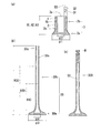
- Example 1 of this invention The manufacturing method of Example 1 of this invention is shown.
- the manufacturing method of Example 2 of this invention is shown.
- the manufacturing method of Example 3 of this invention is shown.
- the pipe end sealing method in the manufacturing method of Example 3 of the present invention will be described.
- a hollow engine valve has a three-part configuration of a valve head portion, a hollow shaft portion, and a shaft end sealing material.
- a semi-finished valve 1 having a diameter enlarged portion 1a, a body portion 1b, and a hollow hole 1s is manufactured from a solid round bar (not shown) as a raw material (first step). The details of this manufacturing method are described in Patent Document 1.
- the diameter of the upper part of the enlarged diameter part 1a and the body part 1b of the semi-finished product 1 of the valve head part 1 is reduced by a rotary swaging process or a spinning process using a spatula drawing, and the final product 10 of the valve head part 10 as shown in FIG. Get.
- the maximum outer diameter ⁇ 1 of the enlarged diameter portion 1a of the semi-finished valve head portion 1 and the maximum outer diameter ⁇ 3 of the enlarged diameter portion 10a of the finished umbrella portion 10 are kept the same, and the semi-finished valve head portion is also completed.
- the inner diameter ⁇ 2 in the enlarged diameter portion 1a of one hollow hole 1s is kept the same as the maximum inner diameter ⁇ 4 of the hollow hole 10s of the valve head part finished product 10.
- the hollow shaft portion S is welded to the opening end portion of the finished valve umbrella portion 10, and the shaft end sealing material C is welded to the opening end portion of the hollow shaft portion S to complete the hollow engine valve 100 of the finished product.
- the hollow hole 10s of the finished valve umbrella part 10 the hollow hole Ss of the hollow shaft part S, and the very shallow hollow hole Cs of the shaft end sealing material C are connected to form the hollow hole S1.
- sodium is enclosed in the hollow hole S1 until reaching FIG. 1c.
- the hollow engine valve has a two-part configuration of a valve head portion and a shaft end sealing material.
- a semi-finished product 2 having an enlarged diameter portion 2a, a body portion 2b, and a hollow hole 2s is manufactured from a solid round bar (not shown) as a material (first step).
- a material first step.
- the diameter of the upper part of the enlarged diameter part 2a and the body part 2b of the semi-finished product 2 of the valve head part 2 is reduced by rotary swaging or spinning by a spatula, thereby completing the finished part 20 of the valve head part 20 as shown in FIG. 2b.
- the maximum outer diameter ⁇ 1 of the enlarged diameter portion 2a of the semi-finished valve head portion 2 and the maximum outer diameter ⁇ 3 of the enlarged diameter portion 20a of the finished umbrella portion 20 are kept the same.
- the inner diameter ⁇ 2 in the enlarged diameter portion 2a of the second hollow hole 2s is kept the same as the maximum inner diameter ⁇ 4 of the hollow hole 20s of the finished valve head portion 20.
- 20b is a trunk
- the shaft end sealing material C is welded to the opening end portion of the valve head part finished product 20 to obtain the finished hollow engine valve 200 (see FIG. 2c).
- the hollow hole 20s of the valve head part finished product 20 and the very shallow hollow hole Cs of the shaft end sealing material C are connected to form a hollow hole S2.
- sodium is enclosed in the hollow hole S2 until reaching FIG. 2c.
- Example 2 since the shaft end sealing material C is welded directly to the opening end of the valve head part finished product 20 without using the hollow shaft part, the length H20 of the valve head part finished product 20 is set to be the same. It must be longer than the length H10 of the finished valve head part 10 of Example 1 (FIG. 2b). For this purpose, if the height H2 of the semi-finished valve head part 2 is the same as the height H1 of the semi-finished valve part 1, the thickness D2 of the body part 2b of the semi-finished valve part 2 is set to It must be thicker than the thickness D1 of the trunk 1b of the semi-finished umbrella part 1.
- Example 3 the hollow engine valve has a single structure in which only the valve head portion is processed. As shown in FIG. 3a, a semi-finished product 3 having an enlarged diameter portion 3a, a body portion 3b, and a hollow hole 3s is manufactured from a solid round bar (not shown) as a material (first step). The details of this manufacturing method are described in Patent Document 1.
- the diameter of the upper part of the enlarged diameter part 3a and the body part 3b of the semi-finished product 3 of the valve head part 3 is reduced by a rotary swaging process or a spinning process using a spatula squeezing, thereby completing the finished product part 30 as shown in FIG. 3b.
- the maximum outer diameter ⁇ 1 of the enlarged diameter portion 3a of the semi-finished valve umbrella portion 3 and the maximum outer diameter ⁇ 3 of the enlarged diameter portion 30a of the finished umbrella portion 30 are kept the same.
- the inner diameter ⁇ 2 in the expanded diameter portion 3a of the third hollow hole 3s is kept the same as the maximum inner diameter ⁇ 4 of the hollow hole 30s of the finished valve head portion 30.
- 30b is a trunk
- the open end portion 30c of the valve head portion finished product 30 is sealed by a closing process to obtain a hollow engine valve 300 (FIG. 3c).
- the hollow hole 30 s of the finished valve umbrella part 30 becomes the hollow hole S 3 of the hollow engine valve 300.
- sodium is enclosed in the hollow hole S3 until reaching FIG. 3c.
- M is a wear resistant alloy.
- Example 3 the opening end 30c of the valve head part finished product 30 is sealed by the closing process to form the hollow engine valve 300 of the finished product.
- the thickness D3 of the body part 3b of the semi-finished valve part 3 is set to the valve It must be thicker than the wall thickness D2 of the trunk 2b of the semi-finished umbrella 2.
- FIG. 4a to 4i show various methods for sealing the open end portion of the valve head portion completed product 30.
- FIG. 4a as a first method, the opening end 30c of FIG. 4a is fixed with dies D and D, and the opening end 30c is sealed by applying a compression force X with a punch P (FIG. 4b). The end part is formed with a wear-resistant wear-resistant alloy M to obtain a finished hollow engine valve 300 (FIG. 4c).
- the open end 30d in FIG. 4d is formed in advance so that only the open end 30d is thicker than the other portions of the body 30b.
- a radial compression force Y is applied to the opening end 30d to reduce the diameter of the opening end 30d (FIG. 4e), and the end is molded with a wear-resistant alloy M for overlaying.
- a hollow engine valve 300 is obtained (FIG. 4f).
- rotary swaging processing, spinning processing, necking processing, and the like are conceivable, and these are appropriately combined.
- a third method there is a method in which a force in the Z direction is applied to the opening end 30c in FIG. 4g by spinning to close the opening end 30c as seen in FIG. 4h. Further, the end portion is sealed with a wear-resistant alloy M for overlaying to obtain a finished hollow engine valve 301 (FIG. 4i).
- a wear-resistant alloy for overlaying in the first to third methods a cobalt-based wear-resistant alloy or a nickel-based wear-resistant alloy can be used.
- the present invention relates to the manufacture of a large-sized hollow engine valve for a marine engine, and is intended to provide a hollow engine valve that is highly accurate, durable, heat-resistant, lightweight, and inexpensive. I believe it has a huge utility in the overall engine design.
- the present invention is considered to be extremely useful industrially as providing a new manufacturing method for manufacturing a small hollow engine valve used for a vehicle engine. That is, with the method of the present invention that can freely combine rotary swaging processing, spinning processing, and necking processing, high accuracy, durability, and heat resistance have been achieved using materials that have been regarded as difficult to process materials. Since it can supply a large volume of hollow engine valves with excellent performance, it can be said that it will be a great gospel even in the automobile industry, where price competition is expected to intensify.
Landscapes
- Engineering & Computer Science (AREA)
- Mechanical Engineering (AREA)
- General Engineering & Computer Science (AREA)
- Chemical & Material Sciences (AREA)
- Combustion & Propulsion (AREA)
- Physics & Mathematics (AREA)
- Geometry (AREA)
- Forging (AREA)
Abstract
有底の底部に拡径部を持つコップ状の弁傘部半完成品の拡径部の上部と胴部を縮径して完成品の弁傘部とする際に、弁傘部単体でも軸端(開放端)を封止するだけで完成品の中空エンジンバルブとすることができる中空エンジンバルブの製造方法を提供することにある。そこで、弁傘部半完成品(3)の拡径部(3a)の上部と胴部(3b)をロータリースエージング加工あるいはスピニング加工あるいはロータリースエージング加工とスピニング加工の組み合わせにより縮径し、あるいはこれらにネッキング加工も組み合わせて縮径し、完成品の弁傘部(30)を得るようにした。
Description
本発明は、内部に中空孔が設けられた中空エンジンバルブを、その製造工程においてロータリースエージング加工あるいはスピニング加工を用いて製造する製造方法、及び該製造方法によって製造された中空エンジンバルブに関するものである。
中空エンジンバルブの弁傘部の製造方法に関しては、本願の発明者により下記特許文献1、2の発明がなされている。下記特許文献1は中空エンジンバルブの弁傘部を冷間のネッキング加工によって成形する方法を開示し、また下記特許文献2は、中空エンジンバルブの弁傘部を温間のネッキング加工によって成形する方法を開示するものである。
従来、中空エンジンバルブの弁傘部は、管材を熱間鍛造によって成形したり、あるいは中実丸棒の先端を熱間鍛造によって拡径し、他端にドリルで中空孔を穿設する等の方法で成形されてきた。しかるに、下記特許文献1、2に記載の方法は、中実丸棒を成形して最初に底部に拡径部を持つコップ状の半完成品を造っておき(第1ステップ)、次にこの半完成品の拡径部上部と胴部を冷間あるいは温間にてネッキング加工を行って完成品とする(第2ステップ)という2段階の工程により成るものであって、それまで冷間あるいは温間にてネッキング加工を行って中空エンジンバルブの弁傘部を成形するという発想のなかった斯界の盲点を突くものとして注目を集めつつある。
しかしながら、下記特許文献1、2に記載の方法には、以下のような問題点が残されていた。すなわち、第一点目は、ネッキング加工では弁傘部の胴部をあまり長くできないという点である。したがって、弁傘部に加えて中空軸部あるいは軸端封止材という別部材が必要であり、部材間の溶着も必要となる。溶着箇所はどうしても強度が低下するので、耐熱性、耐久性において、全体が一部材からなる中空エンジンバルブに比べると、どうしても劣ってしまうことになる。この原因は、まず成形するダイスの構造にあり、ネッキング加工においては最終的にワークをダイスからノックアウトしなければならないが、ワークが余りに長くなるとこのノックアウトに技術的な困難を生じる。
次に、2点目として、たとえノックアウトの問題がなかったとしても、ネッキング加工においては、最初に弁傘部の半完成品の胴部の肉厚を余り厚く設定すると、最終的に必要な厚さに絞れなくなるので、半完成品の胴部の肉厚には限界があり、この点からも、胴部の長さの長い弁傘部の製造には向いていない。すなわち、胴部の肉厚が厚い方が、完成品の弁傘部となったときにその胴部の長さを長くすることができるのは当然であるが、ネッキング加工では絞り上げることのできる胴部の肉厚に限界があるので、胴部の長さの長い弁傘部の製造には向いていないということである。
問題点の3点目は、ネッキング加工においては、あまりにワークの長さが長くなりすぎると、絞り上げの際に座屈を生じるケースが増加するという点である。また、ワークが長いとパンチやダイスの方にも大きな負荷がかかるので、パンチが曲がったりダイスの損傷が激しくなったりする。すなわち金型の型寿命が短くなり、不経済である。
問題点の4点目は、素材とする鋼材が難加工材であった場合、弁傘部の半完成品を完成品の弁傘部に絞り上げる工程において、たとえ温間鍛造で行った場合でも、ダイスの数が相当多くなってしまうという点である。ダイスの数が多くなれば、焼きなましのような中間熱処理工程も多く挟まざるを得なくなり、結局全工程をネッキング加工だけで行うのは無理があって現実的ではないということになる。
具体的な素材に即していえば、例えばSUH38などは、やや難加工材ではあるものの、下記特許文献1、2に記載の方法にて問題なくネッキング加工を行うことができた。しかし、さらに難加工材とされるSUH11やSUH35では次第に技術的な困難が増加して歩留まりが悪くなり、さらに加工性が悪いとされるSUH3においては、現在のところ、下記特許文献1、2の方法では成功に至っていない。
上記より、本発明の課題を以下のように設定した。
<課題1>
中空エンジンバルブの弁傘部の製造において、中実丸棒を成形して、開放端を上にした場合に、有底の底部に拡径部を持つコップ状の半完成品を得る第1ステップと、次にこの半完成品の拡径部の上部と胴部を縮径して完成品の弁傘部とする第2ステップという2段階の工程を保持しつつ、第2ステップにおいて、単体でも軸端(開放端)を封止するだけで完成品の中空エンジンバルブとすることができるだけの長さの胴部を有する完成品の弁傘部を得ることができるように、半完成品の拡径部の上部と胴部を縮径できる技術を開発する。
<課題2>
そのためには、半完成品の胴部の肉厚をある程度厚くしなければならないので、ネッキング加工に替わる縮径の技術を開発する。あるいは、補完としてネッキング加工を用いる場合でも、ダイスの数をできるだけ減らせるような加工方法を開発する。
<課題3>
ネッキング加工においては、ワークの長さが長くなりすぎるとワークに座屈を生じたり、パンチやダイスに損傷が生じたりすることがあるので、このような座屈や損傷を起こすことなく弁傘部を製造できる方法を見出す。
<課題4>
ネッキング加工で行った場合、ダイスの数を増加させねばならなかったり、あるいは座屈や割れを生じて絞り上げができなかったりする難加工素材を用いた場合でも、円滑に拡径部の上部と胴部を縮径でき、弁傘部の完成品を得ることのできる加工方法を開発する。
<課題1>
中空エンジンバルブの弁傘部の製造において、中実丸棒を成形して、開放端を上にした場合に、有底の底部に拡径部を持つコップ状の半完成品を得る第1ステップと、次にこの半完成品の拡径部の上部と胴部を縮径して完成品の弁傘部とする第2ステップという2段階の工程を保持しつつ、第2ステップにおいて、単体でも軸端(開放端)を封止するだけで完成品の中空エンジンバルブとすることができるだけの長さの胴部を有する完成品の弁傘部を得ることができるように、半完成品の拡径部の上部と胴部を縮径できる技術を開発する。
<課題2>
そのためには、半完成品の胴部の肉厚をある程度厚くしなければならないので、ネッキング加工に替わる縮径の技術を開発する。あるいは、補完としてネッキング加工を用いる場合でも、ダイスの数をできるだけ減らせるような加工方法を開発する。
<課題3>
ネッキング加工においては、ワークの長さが長くなりすぎるとワークに座屈を生じたり、パンチやダイスに損傷が生じたりすることがあるので、このような座屈や損傷を起こすことなく弁傘部を製造できる方法を見出す。
<課題4>
ネッキング加工で行った場合、ダイスの数を増加させねばならなかったり、あるいは座屈や割れを生じて絞り上げができなかったりする難加工素材を用いた場合でも、円滑に拡径部の上部と胴部を縮径でき、弁傘部の完成品を得ることのできる加工方法を開発する。
本発明は、上記課題を解決するためになされたものであって、下記に示す解決手段を提供するものである。
<解決手段1>
中空孔が弁傘部の拡径部内において拡径形成されていて、該中空孔の最大内径が弁傘部の胴部の最小外径より大である中空エンジンバルブの製造方法において、
素材の中実丸棒より弁傘部半完成品を製造する第1ステップと、該弁傘部半完成品を冷間鍛造あるいは温間鍛造によって完成品の弁傘部となす第2ステップを有し、
第1ステップにおいては、円筒形状の胴部の一端に胴部と一体の拡径部を有し、胴部に円筒形状中空孔を有し、拡径部側を下とした場合に該円筒形状中空孔は上端が開口され下端が拡径部内において有底である弁傘部半完成品を得、
第2ステップにおいては、弁傘部半完成品を、冷間あるいは温間の雰囲気下で、拡径部の上部及び胴部を、ロータリースエージング加工によって縮径し、あるいはスピニング加工によって縮径し、あるいはロータリースエージング加工とスピニング加工の組み合わせによって縮径し、
完成品の弁傘部の拡径部の最大外径が弁傘部半完成品の拡径部の最大外径のままに保持され、完成品の弁傘部の中空孔の拡径部内に於ける最大内径が弁傘部半完成品の円筒形状中空孔の拡径部内における内径のままに保持されている完成品の弁傘部を得る、
ことを特徴とする、中空エンジンバルブの製造方法。
<解決手段2>
解決手段1の方法によって得られた完成品の弁傘部の開口端部に中空軸部を溶接し、さらに中空軸部に軸端封止材を溶接して完成品の中空エンジンバルブを得る中空エンジンバルブの製造方法。
<解決手段3>
解決手段1の方法によって得られた完成品の弁傘部の開口端部に軸端封止材を溶接して完成品の中空エンジンバルブを得る中空エンジンバルブの製造方法。
<解決手段4>
解決手段1の方法によって得られた完成品の弁傘部の開口端部を封止して完成品の中空エンジンバルブを得る中空エンジンバルブの製造方法。
<解決手段5>
中空孔が弁傘部の拡径部内において拡径形成されていて、該中空孔の最大内径が弁傘部の胴部の最小外径より大である中空エンジンバルブの製造方法において、
素材の中実丸棒より弁傘部半完成品を製造する第1ステップと、該弁傘部半完成品を冷間鍛造あるいは温間鍛造によって完成品の弁傘部となす第2ステップを有し、
第1ステップにおいては、円筒形状の胴部の一端に胴部と一体の拡径部を有し、胴部に円筒形状中空孔を有し、拡径部側を下とした場合に該円筒形状中空孔は上端が開口され下端が拡径部内において有底である弁傘部半完成品を得、
第2ステップにおいて、弁傘部半完成品を、冷間あるいは温間の雰囲気下で、ロータリースエージング加工にネッキング加工を組み合わせることによって縮径し、あるいはスピニング加工にネッキング加工を組み合わせることによって縮径し、あるいはロータリースエージング加工とスピニング加工の組み合わせにさらにネッキング加工を組み合わせることによって縮径し、
完成品の弁傘部の拡径部の最大外径が弁傘部半完成品の拡径部の最大外径のままに保持され、完成品の弁傘部の中空孔の拡径部内に於ける最大内径が弁傘部半完成品の円筒形状中空孔の拡径部内における内径のままに保持されている完成品の弁傘部を得る、
ことを特徴とする中空エンジンバルブの製造方法。
<解決手段6>
解決手段5の方法によって得られた完成品の弁傘部の開口端部に中空軸部を溶接し、さらに中空軸部に軸端封止材を溶接して完成品の中空エンジンバルブを得る中空エンジンバルブの製造方法。
<解決手段7>
解決手段5の方法によって得られた完成品の弁傘部の開口端部に軸端封止材を溶接して完成品の中空エンジンバルブを得る中空エンジンバルブの製造方法。
<解決手段8>
解決手段5の方法によって得られた完成品の弁傘部の開口端部を封止して完成品の中空エンジンバルブを得る中空エンジンバルブの製造方法。
<解決手段9>
解決手段1乃至解決手段8の何れか一つに記載の中空エンジンバルブの製造方法によって製造された中空エンジンバルブ。
<解決手段1>
中空孔が弁傘部の拡径部内において拡径形成されていて、該中空孔の最大内径が弁傘部の胴部の最小外径より大である中空エンジンバルブの製造方法において、
素材の中実丸棒より弁傘部半完成品を製造する第1ステップと、該弁傘部半完成品を冷間鍛造あるいは温間鍛造によって完成品の弁傘部となす第2ステップを有し、
第1ステップにおいては、円筒形状の胴部の一端に胴部と一体の拡径部を有し、胴部に円筒形状中空孔を有し、拡径部側を下とした場合に該円筒形状中空孔は上端が開口され下端が拡径部内において有底である弁傘部半完成品を得、
第2ステップにおいては、弁傘部半完成品を、冷間あるいは温間の雰囲気下で、拡径部の上部及び胴部を、ロータリースエージング加工によって縮径し、あるいはスピニング加工によって縮径し、あるいはロータリースエージング加工とスピニング加工の組み合わせによって縮径し、
完成品の弁傘部の拡径部の最大外径が弁傘部半完成品の拡径部の最大外径のままに保持され、完成品の弁傘部の中空孔の拡径部内に於ける最大内径が弁傘部半完成品の円筒形状中空孔の拡径部内における内径のままに保持されている完成品の弁傘部を得る、
ことを特徴とする、中空エンジンバルブの製造方法。
<解決手段2>
解決手段1の方法によって得られた完成品の弁傘部の開口端部に中空軸部を溶接し、さらに中空軸部に軸端封止材を溶接して完成品の中空エンジンバルブを得る中空エンジンバルブの製造方法。
<解決手段3>
解決手段1の方法によって得られた完成品の弁傘部の開口端部に軸端封止材を溶接して完成品の中空エンジンバルブを得る中空エンジンバルブの製造方法。
<解決手段4>
解決手段1の方法によって得られた完成品の弁傘部の開口端部を封止して完成品の中空エンジンバルブを得る中空エンジンバルブの製造方法。
<解決手段5>
中空孔が弁傘部の拡径部内において拡径形成されていて、該中空孔の最大内径が弁傘部の胴部の最小外径より大である中空エンジンバルブの製造方法において、
素材の中実丸棒より弁傘部半完成品を製造する第1ステップと、該弁傘部半完成品を冷間鍛造あるいは温間鍛造によって完成品の弁傘部となす第2ステップを有し、
第1ステップにおいては、円筒形状の胴部の一端に胴部と一体の拡径部を有し、胴部に円筒形状中空孔を有し、拡径部側を下とした場合に該円筒形状中空孔は上端が開口され下端が拡径部内において有底である弁傘部半完成品を得、
第2ステップにおいて、弁傘部半完成品を、冷間あるいは温間の雰囲気下で、ロータリースエージング加工にネッキング加工を組み合わせることによって縮径し、あるいはスピニング加工にネッキング加工を組み合わせることによって縮径し、あるいはロータリースエージング加工とスピニング加工の組み合わせにさらにネッキング加工を組み合わせることによって縮径し、
完成品の弁傘部の拡径部の最大外径が弁傘部半完成品の拡径部の最大外径のままに保持され、完成品の弁傘部の中空孔の拡径部内に於ける最大内径が弁傘部半完成品の円筒形状中空孔の拡径部内における内径のままに保持されている完成品の弁傘部を得る、
ことを特徴とする中空エンジンバルブの製造方法。
<解決手段6>
解決手段5の方法によって得られた完成品の弁傘部の開口端部に中空軸部を溶接し、さらに中空軸部に軸端封止材を溶接して完成品の中空エンジンバルブを得る中空エンジンバルブの製造方法。
<解決手段7>
解決手段5の方法によって得られた完成品の弁傘部の開口端部に軸端封止材を溶接して完成品の中空エンジンバルブを得る中空エンジンバルブの製造方法。
<解決手段8>
解決手段5の方法によって得られた完成品の弁傘部の開口端部を封止して完成品の中空エンジンバルブを得る中空エンジンバルブの製造方法。
<解決手段9>
解決手段1乃至解決手段8の何れか一つに記載の中空エンジンバルブの製造方法によって製造された中空エンジンバルブ。
中空エンジンバルブの製造方法においては、前記従来技術にては第2ステップにおいて、これまで行われてこなかった盲点となる成形技法が残されており、それは、ロータリースエージング加工を用いる方法あるいはへら絞りによるスピニング加工を用いる方法である。以下、ロータリースエージング加工を主体に述べるが、ロータリースエージング加工に替えてスピニング加工を用いても主旨は変わらない。
ロータリースエージング加工を用いる方法に関しては、中空エンジンバルブの製造方法としてはこれまで試みられることがなかった理由としていくつかの理由が考えられる。まずその一つは、中空エンジンバルブにおける弁傘部の拡径部の問題であり、胴部に比較して短区間で急速に直径が拡径される拡径部をロータリースエージング加工で成形するということには無理があるので、斯界のだれもがそのような方法を思いつかなかったということであると考えられる。
しかしながら、前記特許文献1、2に記載のように工程を2段階に別け、あらかじめ拡径部を有するコップ状の半完成品を製造しておき(第1ステップ)、次に拡径部の上部と胴部を成形する(第2ステップ)という方法をとるのであれば、拡径部の最大外径部分には加工を施さなくても良いので、第2ステップはロータリースエージング加工を用いても技術的な困難なく成形が可能である。
この際、ロータリースエージング加工を用いる長所としては、以下の点が挙げられる。1)半完成品の胴部の肉厚が厚いものであっても加工が可能である。したがって、胴部の延長の長い弁傘部を製造できるので、場合によっては中空軸部や軸端封止材が不要となり、継ぎ目なしの一体の中空エンジンバルブの製造が可能となる。この際、管端を封止する方法としては、据えこみ鍛造によるクロージング、ロータリースエージング加工やスピニング加工によるクロージング、あるいは絞込み加工によるクロージングなどが考えられる。
2)胴部の長い弁傘部の製造においても、ネッキング加工の場合のように座屈を生じることがない。また、ダイスにかかる力もネッキング加工の場合に較べるとはるかに少ないので、金型の損傷が少なく、型寿命が長い。
3)ネッキング加工だけでは成形が難しかった難加工性の素材に対しても、ロータリースエージング加工を用いることにより、成形が可能となる。たとえば、SUH3のような極めて加工性の悪い素材であっても、ロータリースエージング加工を用いれば成形が可能である。
これに対し、ロータリースエージング加工の短所としては、ロータリースエージング機を用いるとネッキング加工に比べて大掛かりになり、加工時間もやや長くなるという点があげられる。
しかしながら、例えば船舶用エンジンのエンジンバルブなどにおいては、必要とされる製品絶対数も車両用のエンジンバルブに比較すれば圧倒的に少なく、またサイズもかなり大型となるので、上記短所が逆に生かされる結果となる。すなわち、船舶用エンジンのエンジンバルブにおいては、1本の製造工程にある程度時間をかけることができるし、またサイズが大型であるので装置が大型化しても他の方法より設備費用がよけいに嵩むということもない。
逆に、ネッキング加工においては、長軸方向からダイスを往復させることになるから、ワークが大型化するとダイスの往復工程が非常に長くなるが、ロータリースエージング加工においては横方向からダイスを極短距離で往復させるだけであるので、大型のエンジンバルブの製造には、むしろロータリースエージング加工の方が向いているとさえいい得る。
ちなみに、船舶用のエンジンにおいては、これまで中空エンジンバルブが使用されている例はあまり見られなかったが、最近、船舶においても燃費の効率化がいわれるようになり、重量の軽い中空エンジンバルブに注目が集まりはじめている。本発明の方法のように、全工程を大きく2つにわけて、第2ステップをロータリースエージング加工にて行う方法は、これまでの中空エンジンバルブの鍛造加工の盲点を突く、非常に魅力的な加工方法になると思われる。
また、車両用エンジンバルブにおいても、ロータリースエージング装置の構成を工夫することにより、拡径部の上部と胴部の成形(第2ステップ)にロータリースエージング加工を用いることは充分に可能であると考えられる。
またさらに、ロータリースエージング加工に替えてへら絞りによるスピニング加工を用いても同様の効果が得られるのは前述のとおりである。あるいは、ロータリースエージング加工やスピニング加工にてある程度まで管径を縮小しておいて、最後にネッキング加工を加えて完成するという方法を用いてもむろんよい。
また逆に、ネッキング加工にてある程度まで管径を縮小しておいて、最後にロータリースエージング加工やスピニング加工を用いても良いし、その後でさらにネッキング加工を加えるのも自由である。
また、完成品の弁傘部から完成品の中空エンジンバルブを得る方法としては、完成品の弁傘部に中空軸部と軸端封止材を溶接する方法、完成品の弁傘部に軸端封止材のみを溶接する方法、あるいは前記のように完成品の弁傘部の開放端を封止することによって全体が一部材のみからなる完成品の中空エンジンバルブとする方法等、さまざまな方法があり得る。
本発明の、解決手段1の発明によれば、素材の中実丸棒より弁傘部半完成品を製造する第1ステップと、該弁傘部半完成品を冷間鍛造あるいは温間鍛造によって完成品の弁傘部となす第2ステップを有しており、第1ステップにおいて得られた弁傘部半完成品の拡径部の最大外径部分には加工を施さず、第2ステップにて拡径部の上部と胴部を縮径して完成品の弁傘部となす方法であるので、これまで中空エンジンバルブの弁傘部の製造方法としては省みられることのなかったロータリースエージング加工あるいはへら絞りによるスピニング加工を用いることが可能となった。
その結果、ネッキング加工では製造が難しかった胴部の長い弁傘部を造ることができるようになった。そして、これにより、全体が一つの部材からなる中空エンジンバルブの製造が可能となった。すなわち、本発明の解決手段1の方法によって充分な長さを有する弁傘部を製造しておき、その開放端を封止するだけで完成品の中空エンジンバルブを得ることができる。このような単一部材から成る中空エンジンバルブは、部材間の継ぎ目がないので、強度的に丈夫で、耐熱性も向上する。また、複数の部材を溶接する手間が省けるので、工程全体の合理化にも大いに資するものがある。
また、ネッキング加工の場合のようにワークに座屈を生じることがないので、ワークが長くなった場合でも製品の歩留まりが向上する。さらに、これまでネッキング加工にては困難であった難加工性の素材も用いることができるようになった。
以上の効果は、また大型の中空エンジンバルブの成形においても大きな効用を齎すものである。すなわち、本発明の、解決手段1の発明によって、例えば船舶用エンジンのエンジンバルブのような大型の中空エンジンバルブの成形が無理なく合理的に行えるようになった。
また、本発明の、解決手段1の発明は、車両エンジンの中空エンジンバルブのような中程度以下のサイズの中空エンジンバルブの製造にも、無論極めて有用である。すなわち、全体が一つの部材からなる中空エンジンバルブが得られる点、ワークが長くなっても座屈を生じず歩留まりが良い点は、車両エンジンの中空エンジンバルブにおいてもその品質向上に直結する。
そしてネッキング加工にては困難であった難加工性の素材を用いることができるようになった点においては、安価で高品質の中空エンジンバルブを大量に提供できるというメリットに結びつく。すなわち、加工性の良い素材は一般に高価であるが、はるかに価格の安い難加工性の素材で、加工性の良い素材を用いた場合と同様の加工精度の中空エンジンバルブを提供できるので、これから激烈な価格競争にさらされることになる自動車業界に対して、大きな強みを提供できるものに他ならない。
本発明の解決手段5の発明においては、第2ステップにおいて、ロータリースエージング加工あるいはスピニング加工あるいはロータリースエージング加工とスピニング加工の組み合わせにネッキング加工を併用するケースが開示されており、この点は、中空エンジンバルブの製造方法において、多くのバラエティ豊かなヴァリエーションを提供するものである。
すなわち、第2ステップにおいて、ロータリースエージング加工あるいはスピニング加工を行った後でネッキング加工を施すことにより、ネッキング加工だけで行う場合よりも格段にダイスの数を減らすことが可能となる。したがって、ネッキング加工も無理なく行えるので製品の歩留まりは向上するし、焼きなましのような中間熱処理の工程を挟む必要もなくなるか、大幅に回数を減少できる。
あるいはまた、第2ステップにおいて、ネッキング加工を行った後でロータリースエージング加工あるいはスピニング加工を施すことにより、ネッキング加工においては無理にワークの長さを長くする必要がなくなり、座屈を生じる率が大幅に減少する。この点は、製品の歩留まりに大きく影響する。また、型寿命も長くなる。
さらにまた、第2ステップにおいて、ロータリースエージング加工、スピニング加工、ネッキング加工を様々に組み合わせることによって、対象となる中空エンジンバルブのサイズや求められる品質に最適の加工方法を見出すことが可能となる。
本発明を実施するための最良の形態を、以下に、図面を参照しながら詳細に説明する。
実施例1は、中空エンジンバルブを、弁傘部、中空軸部、軸端封止材の3部分構成とするものである。図1aに示すように、素材となる中実丸棒(図示せず)から拡径部1a、胴部1b、中空孔1sを有する弁傘部半完成品1を製造する(第1ステップ)。この製造方法については、前記特許文献1に詳細が記載されている。
次に、弁傘部半完成品1の拡径部1aの上部及び胴部1bをロータリースエージング加工あるいはへら絞りによるスピニング加工によって縮径して、図1bに示すような弁傘部完成品10を得る。この際、弁傘部半完成品1の拡径部1aの最大外径φ1と弁傘部完成品10の拡径部10aの最大外径φ3は同一に保たれ、また弁傘部半完成品1の中空孔1sの拡径部1a内の内径φ2は弁傘部完成品10の中空孔10sの最大内径φ4と同一に保たれるようにする。
次に、弁傘部完成品10の開口端部に中空軸部Sを溶着し、さらに中空軸部Sの開口端部に軸端封止材Cを溶着して完成品の中空エンジンバルブ100を得る(図1c参照)。この際、弁傘部完成品10の中空孔10sと中空軸部Sの中空孔Ssと軸端封止材Cのごく浅い中空孔Csが連結されて中空孔S1となる。中空エンジンバルブ100が排気用として用いられる場合には、図1cに至るまでに中空孔S1内部にナトリウムが封入される。
実施例2は、中空エンジンバルブを、弁傘部と軸端封止材の2部分構成とするものである。図2aに示すように、素材となる中実丸棒(図示せず)から拡径部2a、胴部2b、中空孔2sを有する弁傘部半完成品2を製造する(第1ステップ)。この製造方法については、前記特許文献1に詳細が記載されている。
次に、弁傘部半完成品2の拡径部2aの上部及び胴部2bをロータリースエージング加工あるいはへら絞りによるスピニング加工によって縮径して、図2bに示すような弁傘部完成品20を得る。この際、弁傘部半完成品2の拡径部2aの最大外径φ1と弁傘部完成品20の拡径部20aの最大外径φ3は同一に保たれ、また弁傘部半完成品2の中空孔2sの拡径部2a内の内径φ2は弁傘部完成品20の中空孔20sの最大内径φ4と同一に保たれるようにする。なお、20bは弁傘部完成品20の胴部である。
次に、弁傘部完成品20の開口端部に軸端封止材Cを溶着して完成品の中空エンジンバルブ200を得る(図2c参照)。この際、弁傘部完成品20の中空孔20sと軸端封止材Cのごく浅い中空孔Csが連結されて中空孔S2となる。中空エンジンバルブ200が排気用として用いられる場合には、図2cに至るまでに中空孔S2内部にナトリウムが封入される。
なお、実施例2にては、弁傘部完成品20の開口端部に中空軸部を介さず直接軸端封止材Cを溶着するため、弁傘部完成品20の長さH20は実施例1の弁傘部完成品10の長さH10より長くしておかなければならない(図2b)。そしてそのためには、弁傘部半完成品2の高さH2が弁傘部半完成品1の高さH1と同一の場合、弁傘部半完成品2の胴部2bの肉厚D2を弁傘部半完成品1の胴部1bの肉厚D1より厚くしておかなければならない。
実施例3は、中空エンジンバルブを、弁傘部のみを加工して造る単体構成とするものである。図3aに示すように、素材となる中実丸棒(図示せず)から拡径部3a、胴部3b、中空孔3sを有する弁傘部半完成品3を製造する(第1ステップ)。この製造方法については、前記特許文献1に詳細が記載されている。
次に、弁傘部半完成品3の拡径部3aの上部及び胴部3bをロータリースエージング加工あるいはへら絞りによるスピニング加工によって縮径して、図3bに示すような弁傘部完成品30を得る。この際、弁傘部半完成品3の拡径部3aの最大外径φ1と弁傘部完成品30の拡径部30aの最大外径φ3は同一に保たれ、また弁傘部半完成品3の中空孔3sの拡径部3a内の内径φ2は弁傘部完成品30の中空孔30sの最大内径φ4と同一に保たれるようにする。なお、30bは弁傘部完成品30の胴部である。
次に、弁傘部完成品30の開口端部30cをクロージング加工にて封止し、中空エンジンバルブ300を得る(図3c)。この際、弁傘部完成品30の中空孔30sが中空エンジンバルブ300の中空孔S3となる。中空エンジンバルブ300が排気用として用いられる場合には、図3cに至るまでに中空孔S3内部にナトリウムが封入される。なお、図3cにおけるMは耐磨耗合金である。
なお、実施例3にては、弁傘部完成品30の開口端部30cをクロージング加工にて封止して完成品の中空エンジンバルブ300とするため、弁傘部完成品30の長さH30は実施例2の弁傘部完成品20の長さH20よりも長くしておかなければならない(図3b)。そしてそのためには、弁傘部半完成品3の高さH3が弁傘部半完成品2の高さH2と同一の場合、弁傘部半完成品3の胴部3bの肉厚D3を弁傘部半完成品2の胴部2bの肉厚D2より厚くしておかなければならない。
図4a~図4iに、弁傘部完成品30の開口端部を封止する様々な方法を示す。まず第1の方法としては、図4aの開口端部30cをダイスD、Dで固定してパンチPにて圧縮力Xを加えて開口端部30cを封止し(図4b)、次に肉盛用の耐磨耗合金Mにて端部を成形して完成品の中空エンジンバルブ300を得る(図4c)。
次に、第2の方法として、図4dの開口端部30dは、第2ステップにおいて、予め開口端部30dのみを胴部30bの他の部分よりも肉厚に成形しておく。この開口端部30dに半径方向の圧縮力Yを加えて開口端部30dを縮径封止し(図4e)、肉盛用の耐磨耗合金Mにて端部を成形して完成品の中空エンジンバルブ300を得る(図4f)。このための工法としては、ロータリースエージング加工、スピニング加工、ネッキング加工などが考えられ、適宜それらを組み合わせる。
次に、第3の方法として、図4gの開口端部30cに、スピニング加工によってZ方向の力を加えて開口端部30cを図4hに見るようにクロージング加工する方法がある。さらに端部を肉盛用の耐磨耗合金Mにて封止成形して完成品の中空エンジンバルブ301を得る(図4i)。なお、上記第1~第3の方法における肉盛用の耐磨耗合金としてはコバルトベースの耐磨耗合金、あるいはニッケルベースの耐磨耗合金などが使用できる。
本発明は、上記のように、まずは船舶用エンジンの大型の中空エンジンバルブの製造に関して、高精度で耐久性、耐熱性に優れ、しかも軽量で安価な中空エンジンバルブを提供するものとして、船舶用エンジンの設計全体に多大な効用を齎すものであると信じている。
すなわち、これまではエンジンバルブを中空に構成するという発想が余り見られなかった船舶用エンジンの世界においても、地球温暖化の防止や低燃費化による燃料の節約などの効果から中空エンジンバルブの効用が改めて見直され、合理的で品質精度の高い大型の中空エンジンバルブの製造方法が希求されるようになってきている。本発明は、このような船舶用エンジンの大型の中空エンジンバルブに対して即応できる技術内容を提供するものである。
次に、本発明は、車両用エンジンに用いられる小型の中空エンジンバルブの製造に関しても、新たな製造方法を提供するものとして、産業上極めて有益であると考える。すなわち、ロータリースエージング加工、スピニング加工、ネッキング加工を自在に組み合わせることのできる本発明の方法によって、これまで安価ではあるが難加工性材とされてきた材料を用いて高精度で耐久性、耐熱性に優れた中空エンジンバルブを大量に供給できるので、これから価格競争が熾烈になることが予想される自動車産業においても大きな福音を齎すものであるといえる。
1 弁傘部半完成品
1a 拡径部
1b 胴部
1s 中空孔
10 弁傘部完成品
10a 拡径部
10b 胴部
10s 中空孔
100 中空エンジンバルブ
2 弁傘部半完成品
2a 拡径部
2b 胴部
2s 中空孔
20 弁傘部完成品
20a 拡径部
20b 胴部
20s 中空孔
200 中空エンジンバルブ
3 弁傘部半完成品
3a 拡径部
3b 胴部
3s 中空孔
30 弁傘部完成品
30a 拡径部
30b 胴部
30c 開口端部
30d 開口端部
30s 中空孔
300 中空エンジンバルブ
301 中空エンジンバルブ
C 軸端封止材
Cs 中空孔
D ダイス
D1 肉厚
D2 肉厚
D3 肉厚
H1 高さ
H10 長さ
H2 高さ
H20 長さ
H3 高さ
H30 長さ
M 耐磨耗合金
P パンチ
S 中空軸部
S1 中空孔
S2 中空孔
S3 中空孔
Ss 中空孔
X 圧縮力
Y 圧縮力
Z 方向
φ1 最大外径
φ2 内径
φ3 最大外径
φ4 最大内径
1a 拡径部
1b 胴部
1s 中空孔
10 弁傘部完成品
10a 拡径部
10b 胴部
10s 中空孔
100 中空エンジンバルブ
2 弁傘部半完成品
2a 拡径部
2b 胴部
2s 中空孔
20 弁傘部完成品
20a 拡径部
20b 胴部
20s 中空孔
200 中空エンジンバルブ
3 弁傘部半完成品
3a 拡径部
3b 胴部
3s 中空孔
30 弁傘部完成品
30a 拡径部
30b 胴部
30c 開口端部
30d 開口端部
30s 中空孔
300 中空エンジンバルブ
301 中空エンジンバルブ
C 軸端封止材
Cs 中空孔
D ダイス
D1 肉厚
D2 肉厚
D3 肉厚
H1 高さ
H10 長さ
H2 高さ
H20 長さ
H3 高さ
H30 長さ
M 耐磨耗合金
P パンチ
S 中空軸部
S1 中空孔
S2 中空孔
S3 中空孔
Ss 中空孔
X 圧縮力
Y 圧縮力
Z 方向
φ1 最大外径
φ2 内径
φ3 最大外径
φ4 最大内径
Claims (9)
- 中空孔が弁傘部の拡径部内において拡径形成されていて、該中空孔の最大内径が弁傘部の胴部の最小外径より大である中空エンジンバルブの製造方法において、
素材の中実丸棒より弁傘部半完成品を製造する第1ステップと、該弁傘部半完成品を冷間鍛造あるいは温間鍛造によって完成品の弁傘部となす第2ステップを有し、
第1ステップにおいては、円筒形状の胴部の一端に胴部と一体の拡径部を有し、胴部に円筒形状中空孔を有し、拡径部側を下とした場合に該円筒形状中空孔は上端が開口され下端が拡径部内において有底である弁傘部半完成品を得、
第2ステップにおいては、弁傘部半完成品を、冷間あるいは温間の雰囲気下で、拡径部の上部及び胴部を、ロータリースエージング加工によって縮径し、あるいはスピニング加工によって縮径し、あるいはロータリースエージング加工とスピニング加工の組み合わせによって縮径し、
完成品の弁傘部の拡径部の最大外径が弁傘部半完成品の拡径部の最大外径のままに保持され、完成品の弁傘部の中空孔の拡径部内に於ける最大内径が弁傘部半完成品の円筒形状中空孔の拡径部内における内径のままに保持されている完成品の弁傘部を得る、
ことを特徴とする、中空エンジンバルブの製造方法。 - 請求項1の方法によって得られた完成品の弁傘部の開口端部に中空軸部を溶接し、さらに中空軸部に軸端封止材を溶接して完成品の中空エンジンバルブを得る中空エンジンバルブの製造方法。
- 請求項1の方法によって得られた完成品の弁傘部の開口端部に軸端封止材を溶接して完成品の中空エンジンバルブを得る中空エンジンバルブの製造方法。
- 請求項1の方法によって得られた完成品の弁傘部の開口端部を封止して完成品の中空エンジンバルブを得る中空エンジンバルブの製造方法。
- 中空孔が弁傘部の拡径部内において拡径形成されていて、該中空孔の最大内径が弁傘部の胴部の最小外径より大である中空エンジンバルブの製造方法において、
素材の中実丸棒より弁傘部半完成品を製造する第1ステップと、該弁傘部半完成品を冷間鍛造あるいは温間鍛造によって完成品の弁傘部となす第2ステップを有し、
第1ステップにおいては、円筒形状の胴部の一端に胴部と一体の拡径部を有し、胴部に円筒形状中空孔を有し、拡径部側を下とした場合に該円筒形状中空孔は上端が開口され下端が拡径部内において有底である弁傘部半完成品を得、
第2ステップにおいて、弁傘部半完成品を、冷間あるいは温間の雰囲気下で、ロータリースエージング加工にネッキング加工を組み合わせることによって縮径し、あるいはスピニング加工にネッキング加工を組み合わせることによって縮径し、あるいはロータリースエージング加工とスピニング加工の組み合わせにさらにネッキング加工を組み合わせることによって縮径し、
完成品の弁傘部の拡径部の最大外径が弁傘部半完成品の拡径部の最大外径のままに保持され、完成品の弁傘部の中空孔の拡径部内に於ける最大内径が弁傘部半完成品の円筒形状中空孔の拡径部内における内径のままに保持されている完成品の弁傘部を得る、
ことを特徴とする中空エンジンバルブの製造方法。 - 請求項5の方法によって得られた完成品の弁傘部の開口端部に中空軸部を溶接し、さらに中空軸部に軸端封止材を溶接して完成品の中空エンジンバルブを得る中空エンジンバルブの製造方法。
- 請求項5の方法によって得られた完成品の弁傘部の開口端部に軸端封止材を溶接して完成品の中空エンジンバルブを得る中空エンジンバルブの製造方法。
- 請求項5の方法によって得られた完成品の弁傘部の開口端部を封止して完成品の中空エンジンバルブを得る中空エンジンバルブの製造方法。
- 請求項1~8の中空エンジンバルブの製造方法のうちのいずれかの製造方法によって製造された中空エンジンバルブ。
Applications Claiming Priority (2)
| Application Number | Priority Date | Filing Date | Title |
|---|---|---|---|
| JP2010-040127 | 2010-02-25 | ||
| JP2010040127 | 2010-02-25 |
Publications (1)
| Publication Number | Publication Date |
|---|---|
| WO2011104903A1 true WO2011104903A1 (ja) | 2011-09-01 |
Family
ID=44506343
Family Applications (1)
| Application Number | Title | Priority Date | Filing Date |
|---|---|---|---|
| PCT/JP2010/061934 Ceased WO2011104903A1 (ja) | 2010-02-25 | 2010-07-15 | 中空エンジンバルブの製造方法及び中空エンジンバルブ |
Country Status (1)
| Country | Link |
|---|---|
| WO (1) | WO2011104903A1 (ja) |
Cited By (7)
| Publication number | Priority date | Publication date | Assignee | Title |
|---|---|---|---|---|
| WO2013114989A1 (ja) * | 2012-01-30 | 2013-08-08 | 三菱重工業株式会社 | 中空エンジンバルブの製造方法 |
| US20140033533A1 (en) * | 2011-03-22 | 2014-02-06 | Yoshimura Company | Method for manufacturing hollow engine valve |
| CN107109974A (zh) * | 2014-08-27 | 2017-08-29 | 富士特殊气门有限公司 | 空心发动机气门及其制造方法 |
| KR20190119095A (ko) * | 2017-02-15 | 2019-10-21 | 페데랄-모굴 밸브트레인 게엠베하 | 크로스 웨지 롤링 포펫 밸브를 위한 방법(method for cross-wedge rolling poppet valves) |
| WO2019223908A1 (de) * | 2018-05-23 | 2019-11-28 | Federal-Mogul Valvetrain Gmbh | Verfahren zur herstellung eines hohlventils für verbrennungsmotoren |
| WO2020004286A1 (ja) | 2018-06-28 | 2020-01-02 | 株式会社東亜鍛工所 | 中空エンジンバルブの製造方法 |
| WO2020129934A1 (ja) * | 2018-12-21 | 2020-06-25 | 三菱日立パワーシステムズ株式会社 | スラグクラッシャ、ガス化炉、ガス化複合発電設備、及びスラグクラッシャの組立方法 |
Citations (6)
| Publication number | Priority date | Publication date | Assignee | Title |
|---|---|---|---|---|
| JP2006170122A (ja) * | 2004-12-17 | 2006-06-29 | Fuji Oozx Inc | 内燃機関用バルブスプリングリテーナ |
| JP2006275038A (ja) * | 2005-03-28 | 2006-10-12 | Sango Co Ltd | 熱回収器 |
| JP2008069766A (ja) * | 2006-09-13 | 2008-03-27 | Sango Co Ltd | 消音器の製造方法 |
| JP2008202505A (ja) * | 2007-02-20 | 2008-09-04 | Sango Co Ltd | ハニカム構造体内蔵流体処理装置の製造方法 |
| JP2009185655A (ja) * | 2008-02-05 | 2009-08-20 | Toyota Motor Corp | 吸排気バルブの製造方法 |
| JP4390291B1 (ja) * | 2008-09-18 | 2009-12-24 | 株式会社 吉村カンパニー | 中空エンジンバルブの弁傘部の製造方法及び中空エンジンバルブ |
-
2010
- 2010-07-15 WO PCT/JP2010/061934 patent/WO2011104903A1/ja not_active Ceased
Patent Citations (6)
| Publication number | Priority date | Publication date | Assignee | Title |
|---|---|---|---|---|
| JP2006170122A (ja) * | 2004-12-17 | 2006-06-29 | Fuji Oozx Inc | 内燃機関用バルブスプリングリテーナ |
| JP2006275038A (ja) * | 2005-03-28 | 2006-10-12 | Sango Co Ltd | 熱回収器 |
| JP2008069766A (ja) * | 2006-09-13 | 2008-03-27 | Sango Co Ltd | 消音器の製造方法 |
| JP2008202505A (ja) * | 2007-02-20 | 2008-09-04 | Sango Co Ltd | ハニカム構造体内蔵流体処理装置の製造方法 |
| JP2009185655A (ja) * | 2008-02-05 | 2009-08-20 | Toyota Motor Corp | 吸排気バルブの製造方法 |
| JP4390291B1 (ja) * | 2008-09-18 | 2009-12-24 | 株式会社 吉村カンパニー | 中空エンジンバルブの弁傘部の製造方法及び中空エンジンバルブ |
Cited By (27)
| Publication number | Priority date | Publication date | Assignee | Title |
|---|---|---|---|---|
| US20140033533A1 (en) * | 2011-03-22 | 2014-02-06 | Yoshimura Company | Method for manufacturing hollow engine valve |
| US9302317B2 (en) * | 2011-03-22 | 2016-04-05 | Mitsubishi Heavy Industries, Ltd. | Method for manufacturing hollow engine valve |
| KR101649845B1 (ko) * | 2012-01-30 | 2016-08-22 | 가부시키가이샤 요시무라 캄파니 | 중공 엔진 밸브의 제조 방법 |
| WO2013114989A1 (ja) * | 2012-01-30 | 2013-08-08 | 三菱重工業株式会社 | 中空エンジンバルブの製造方法 |
| CN103998726A (zh) * | 2012-01-30 | 2014-08-20 | 三菱重工业株式会社 | 空心发动机气门的制造方法 |
| US20140366373A1 (en) * | 2012-01-30 | 2014-12-18 | Mitsubishi Heavy Industries, Ltd. | Method for producing a hollow engine valve |
| EP2811126A4 (en) * | 2012-01-30 | 2015-07-29 | Mitsubishi Heavy Ind Ltd | METHOD FOR PRODUCING A MOTORHOLE VALVE |
| JP2013155676A (ja) * | 2012-01-30 | 2013-08-15 | Mitsubishi Heavy Ind Ltd | 中空エンジンバルブの製造方法 |
| KR20140092934A (ko) * | 2012-01-30 | 2014-07-24 | 미츠비시 쥬고교 가부시키가이샤 | 중공 엔진 밸브의 제조 방법 |
| US9427795B2 (en) | 2012-01-30 | 2016-08-30 | Fuji Hollow Valve Inc. | Method for producing a hollow engine valve |
| CN107109974B (zh) * | 2014-08-27 | 2020-03-20 | 富士特殊气门有限公司 | 空心发动机气门及其制造方法 |
| CN107109974A (zh) * | 2014-08-27 | 2017-08-29 | 富士特殊气门有限公司 | 空心发动机气门及其制造方法 |
| US10526933B2 (en) | 2014-08-27 | 2020-01-07 | Fuji Hollow Valve Inc. | Hollow engine valve and manufacturing method therefor |
| CN111502792A (zh) * | 2014-08-27 | 2020-08-07 | 富士特殊气门有限公司 | 空心发动机气门 |
| US11215091B2 (en) | 2014-08-27 | 2022-01-04 | Fuji Hollow Valve Inc. | Hollow engine valve and manufacturing method therefor |
| KR20190119095A (ko) * | 2017-02-15 | 2019-10-21 | 페데랄-모굴 밸브트레인 게엠베하 | 크로스 웨지 롤링 포펫 밸브를 위한 방법(method for cross-wedge rolling poppet valves) |
| KR102429228B1 (ko) * | 2017-02-15 | 2022-08-03 | 페데랄-모굴 밸브트레인 게엠베하 | 크로스 웨지 롤링 포펫 밸브를 위한 방법(method for cross-wedge rolling poppet valves) |
| JP2020508875A (ja) * | 2017-02-15 | 2020-03-26 | フェデラル−モーグル バルブトレイン ゲーエムベーハーFederal−Mogul Valvetrain Gmbh | ディスクバルブをクロスウェッジ圧延する方法 |
| JP7007390B2 (ja) | 2017-02-15 | 2022-01-24 | フェデラル-モーグル バルブトレイン ゲーエムベーハー | ディスクバルブをクロスウェッジ圧延する方法 |
| WO2019223908A1 (de) * | 2018-05-23 | 2019-11-28 | Federal-Mogul Valvetrain Gmbh | Verfahren zur herstellung eines hohlventils für verbrennungsmotoren |
| US11654471B2 (en) | 2018-05-23 | 2023-05-23 | Federal-Mogul Valvetrain Gmbh | Method for producing a hollow valve for internal combustion engines |
| EP3815811A4 (en) * | 2018-06-28 | 2022-03-16 | Toa Forging Co., Ltd. | HOLLOW ENGINE VALVE MANUFACTURING METHOD |
| WO2020004286A1 (ja) | 2018-06-28 | 2020-01-02 | 株式会社東亜鍛工所 | 中空エンジンバルブの製造方法 |
| JP2020099867A (ja) * | 2018-12-21 | 2020-07-02 | 三菱日立パワーシステムズ株式会社 | スラグクラッシャ、ガス化炉、ガス化複合発電設備、及びスラグクラッシャの組立方法 |
| WO2020129934A1 (ja) * | 2018-12-21 | 2020-06-25 | 三菱日立パワーシステムズ株式会社 | スラグクラッシャ、ガス化炉、ガス化複合発電設備、及びスラグクラッシャの組立方法 |
| JP7171417B2 (ja) | 2018-12-21 | 2022-11-15 | 三菱重工業株式会社 | スラグクラッシャ、ガス化炉、ガス化複合発電設備、及びスラグクラッシャの組立方法 |
| US12121903B2 (en) | 2018-12-21 | 2024-10-22 | Mitsubishi Heavy Industries, Ltd. | Slag crusher, gasifier, integrated gasification combined cycle, and assembly method of slag crusher |
Similar Documents
| Publication | Publication Date | Title |
|---|---|---|
| JP4390291B1 (ja) | 中空エンジンバルブの弁傘部の製造方法及び中空エンジンバルブ | |
| WO2011104903A1 (ja) | 中空エンジンバルブの製造方法及び中空エンジンバルブ | |
| JP3772110B2 (ja) | 中空なステアリングラック軸およびその製造方法 | |
| JP5297402B2 (ja) | 金属ナトリウム封入エンジンバルブの製造方法 | |
| JP4929408B1 (ja) | 中空エンジンバルブの製造方法 | |
| EP2811126B1 (en) | Method for producing a hollow engine valve | |
| US8881391B2 (en) | Method for producing hollow engine valve | |
| JP4526097B1 (ja) | 中空エンジンバルブの弁傘部の製造方法及び中空エンジンバルブの弁傘部のプレス装置及び中空エンジンバルブ | |
| US10279440B2 (en) | Precision forming method of high-efficiency and near-net hollow valve blank of engine | |
| CN107109974B (zh) | 空心发动机气门及其制造方法 | |
| US11260448B2 (en) | Method for the production of hollow chamber valves | |
| CN106141049A (zh) | 小口径大锥度锥形环形件锻造成形工艺 | |
| CN106583631A (zh) | Tc4钛合金空心轴颈锻件近等温锻造成形方法 | |
| CN106493282A (zh) | Ti1023钛合金空心轴颈锻件近等温锻造成形方法 | |
| CN105397417A (zh) | 高温合金板形锻件的轧制方法 | |
| JP2009226410A (ja) | 中空バルブの製造方法 | |
| CN100506423C (zh) | 一种超长加厚端钻杆的制造方法 | |
| CN115502312A (zh) | 带三个内筋的高强轻质2a14铝合金薄壁锥筒环件的成形工艺 | |
| CN109570432A (zh) | 一种基于冲孔用剪切模具的铝合金锻环制造方法 | |
| US20230358151A1 (en) | Hollow engine valve and production method thereof | |
| RU58964U1 (ru) | Конструкция биметаллического воротникового фланца и инструмент для штамповки его на прессе двойного действия |
Legal Events
| Date | Code | Title | Description |
|---|---|---|---|
| 121 | Ep: the epo has been informed by wipo that ep was designated in this application |
Ref document number: 10846566 Country of ref document: EP Kind code of ref document: A1 |
|
| NENP | Non-entry into the national phase |
Ref country code: DE |
|
| 122 | Ep: pct application non-entry in european phase |
Ref document number: 10846566 Country of ref document: EP Kind code of ref document: A1 |