WO2011104828A1 - 環境測定システム及び環境測定方法 - Google Patents
環境測定システム及び環境測定方法 Download PDFInfo
- Publication number
- WO2011104828A1 WO2011104828A1 PCT/JP2010/052817 JP2010052817W WO2011104828A1 WO 2011104828 A1 WO2011104828 A1 WO 2011104828A1 JP 2010052817 W JP2010052817 W JP 2010052817W WO 2011104828 A1 WO2011104828 A1 WO 2011104828A1
- Authority
- WO
- WIPO (PCT)
- Prior art keywords
- temperature
- optical fiber
- measurement
- measurement unit
- coating layer
- Prior art date
- Legal status (The legal status is an assumption and is not a legal conclusion. Google has not performed a legal analysis and makes no representation as to the accuracy of the status listed.)
- Ceased
Links
Images





Classifications
-
- G—PHYSICS
- G01—MEASURING; TESTING
- G01K—MEASURING TEMPERATURE; MEASURING QUANTITY OF HEAT; THERMALLY-SENSITIVE ELEMENTS NOT OTHERWISE PROVIDED FOR
- G01K11/00—Measuring temperature based upon physical or chemical changes not covered by groups G01K3/00, G01K5/00, G01K7/00 or G01K9/00
- G01K11/32—Measuring temperature based upon physical or chemical changes not covered by groups G01K3/00, G01K5/00, G01K7/00 or G01K9/00 using changes in transmittance, scattering or luminescence in optical fibres
-
- G—PHYSICS
- G01—MEASURING; TESTING
- G01K—MEASURING TEMPERATURE; MEASURING QUANTITY OF HEAT; THERMALLY-SENSITIVE ELEMENTS NOT OTHERWISE PROVIDED FOR
- G01K3/00—Thermometers giving results other than momentary value of temperature
- G01K3/02—Thermometers giving results other than momentary value of temperature giving means values; giving integrated values
- G01K3/06—Thermometers giving results other than momentary value of temperature giving means values; giving integrated values in respect of space
-
- G—PHYSICS
- G01—MEASURING; TESTING
- G01P—MEASURING LINEAR OR ANGULAR SPEED, ACCELERATION, DECELERATION, OR SHOCK; INDICATING PRESENCE, ABSENCE, OR DIRECTION, OF MOVEMENT
- G01P5/00—Measuring speed of fluids, e.g. of air stream; Measuring speed of bodies relative to fluids, e.g. of ship, of aircraft
- G01P5/10—Measuring speed of fluids, e.g. of air stream; Measuring speed of bodies relative to fluids, e.g. of ship, of aircraft by measuring thermal variables
-
- G—PHYSICS
- G01—MEASURING; TESTING
- G01K—MEASURING TEMPERATURE; MEASURING QUANTITY OF HEAT; THERMALLY-SENSITIVE ELEMENTS NOT OTHERWISE PROVIDED FOR
- G01K11/00—Measuring temperature based upon physical or chemical changes not covered by groups G01K3/00, G01K5/00, G01K7/00 or G01K9/00
- G01K11/32—Measuring temperature based upon physical or chemical changes not covered by groups G01K3/00, G01K5/00, G01K7/00 or G01K9/00 using changes in transmittance, scattering or luminescence in optical fibres
- G01K11/324—Measuring temperature based upon physical or chemical changes not covered by groups G01K3/00, G01K5/00, G01K7/00 or G01K9/00 using changes in transmittance, scattering or luminescence in optical fibres using Raman scattering
Definitions
- the present invention relates to an environmental measurement system and an environmental measurement method for measuring temperature and wind speed in factories, office buildings, data centers, and the like.
- Temperature sensors that can be used for this type of application include thermocouples, platinum resistance thermometers, thermistors, and expansion thermometers.
- the wind speed sensors include hot-wire wind sensors, vane wind turbine sensors, There is a sonic wind speed sensor.
- optical fiber temperature measuring device using an optical fiber as a temperature sensor.
- An optical fiber temperature measurement device is a device that measures the temperature by entering a laser beam into an optical fiber and detecting the Raman backscattered light generated in the optical fiber. The temperature distribution along the length of the optical fiber Can be measured in a short time.
- a flow velocity measuring device using an optical fiber as a flow velocity sensor has also been proposed. In this type of flow velocity measuring device, the optical fiber is heated by a heating element, and the flow velocity of the fluid is calculated based on the temperature change. It is conceivable to measure the wind speed in a facility such as an office building using this type of flow velocity measuring device.
- the optical fiber is heated by a heating element.
- a power source and wiring for supplying power to the heating element are required.
- power consumption increases by the amount of power supplied to the heating element.
- an optical fiber including a first measurement unit and a second measurement unit that are different in at least one of a heat capacity and a thermal conductivity of a coating layer, light is incident on the optical fiber, and from the optical fiber
- a temperature measurement device that receives the emitted backscattered light and measures the temperature distribution in the length direction of the optical fiber; and the first measurement by analyzing the temporal change of the temperature distribution output from the temperature measurement device.
- an analysis device for calculating the temperature and the wind speed at the measurement place where the second measurement unit is arranged.
- an optical fiber having a first measurement unit and a second measurement unit in which at least one of the heat capacity and the thermal conductivity of the coating layer is different is used.
- a 1st measurement part and a 2nd measurement part are arrange
- the temperatures detected by the first measurement unit and the second measurement unit both change, but the fluctuation range of the temperature detected by the first measurement unit due to the strength of the wind The temperature fluctuation range detected by the second measurement unit is different.
- the wind speed can be calculated from the ratio of the temperature fluctuation range detected by the first measurement unit and the temperature fluctuation range detected by the second measurement unit. Moreover, the temperature of a measurement place is obtained by the average value of the temperature detected by the 1st measurement part or the 2nd measurement part, for example.
- the wind speed can be measured without using a heating element.
- a heating element for example, by providing a plurality of first measurement units and a plurality of second measurement units in one optical fiber, it is possible to measure temperatures and wind speeds at a large number of measurement locations with one optical fiber.
- two optical fibers in which at least one of the heat capacity and the thermal conductivity of the coating layer are different may be used.
- FIG. 1 is a block diagram showing an outline of the environment measurement system according to the first embodiment.
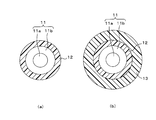
- FIGS. 2A and 2B are cross-sectional views of the optical fiber.
- FIG. 3 is a diagram showing a spectrum of backscattered light.
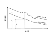
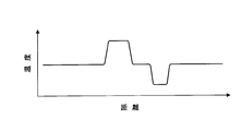
- FIG. 4 is a diagram illustrating an example of a change with time of the intensity of Raman scattered light. 5 calculates the I 1 / I 2 ratio for each time based on the change over time of the intensity of Raman scattered light shown in FIG. 4, and the horizontal axis (time) in FIG. It is a figure which shows the result of having converted signal intensity
- FIG. 6 is a diagram illustrating an example of a change in temperature measured by the temperature measurement device when a wind having a constant wind speed is applied to the optical fiber.
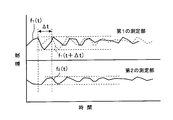
- FIG. 7 is a diagram illustrating an example of a method for calculating the delay time ⁇ t between the temperature fluctuation in the first measurement unit and the temperature fluctuation in the second measurement unit.
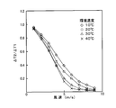
- FIG. 8 is a diagram showing the relationship between the wind speed and the value of ⁇ T2 / ⁇ T1 for each environmental temperature.
- FIG. 9 is a flowchart illustrating the environment measurement method according to the first embodiment.
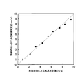
- FIG. 10 is a diagram illustrating a correlation between a wind speed measurement value obtained by the environmental measurement method according to the first embodiment and a wind speed measurement value obtained by a hot-wire anemometer.
- FIG. 11 is a block diagram illustrating an outline of an environment measurement system according to the second embodiment.
- FIG. 12 is a diagram (part 1) illustrating an optical fiber of an environment measurement system according to another embodiment.
- FIG. 13 is a diagram (part 2) illustrating an optical fiber of an environment measurement system according to another embodiment.
- FIG. 1 is a block diagram showing an outline of an environmental measurement system according to the first embodiment, and FIGS. 2A and 2B are cross-sectional views of optical fibers.
- the environment measurement system includes an optical fiber 10, a temperature measurement device 20, and an analysis device (computer) 25.
- the optical fiber 10 includes a core wire 11 through which laser light propagates, a first coating layer 12 that covers the core wire 11, and a first coating layer 12 that is disposed at a predetermined position in the length direction of the optical fiber 10. And a second coating layer 13.
- FIG. 2A shows a cross section of a portion where the first covering layer 12 is exposed
- FIG. 2B shows a cross section of a portion where the second covering layer 13 is disposed.
- the core wire 11 has a core 11a and a clad 11b disposed around the core 11a, and a difference in refractive index between the core 11a and the clad 11b. The light is confined in the core 11a and transmitted.
- the first covering layer 12 is made of a polymer resin such as polyurethane, for example, and covers the entire core wire 11 with a uniform thickness.
- the second covering layer 13 may be formed of the same material as the first covering layer 12 or may be formed of a different material.
- the optical fiber 10 only needs to have a portion with a thick coating layer and a portion with a thin coating layer along its length direction.
- the 2nd coating layer 13 shall be formed with the silicone resin.
- the heat capacity and thermal conductivity of the coating layer vary depending on the thickness and material of the coating layer. Therefore, it can be said that the optical fiber 10 used in the present embodiment has two regions having different heat capacities or thermal conductivities.
- the portion of only the first coating layer 12 and the portion of the second coating layer 13 are arranged at the same measurement location, and the temperature and wind speed of the measurement location are determined. taking measurement.
- the second coating layer 13 may be disposed at one point in the length direction of the optical fiber 10. It is necessary to dispose a plurality along the vertical direction.
- the temperature measuring device 20 includes a laser light source 21, a beam splitter 22, a photodetector 23, and a data processing unit 24.
- the optical fiber 10 (core wire 11) is optically connected to the laser light source 21 and the beam splitter 22.
- Laser light (laser pulse) is emitted from the laser light source 21 at regular time intervals.
- the laser light emitted from the laser light source 21 passes through the beam splitter 22 and enters the optical fiber 10 (core wire 11), and propagates in the optical fiber 10 in the length direction.
- a part of the light propagating in the optical fiber 10 is backscattered by the molecules constituting the optical fiber 10 (core wire 11).
- the back-scattered light returns through the optical fiber 10, exits from the light source side end, is reflected by the beam splitter 12, and is input to the photodetector 23.
- the backscattered light generated in the optical fiber 10 includes Rayleigh scattered light, Brillouin scattered light, and Raman scattered light.
- Rayleigh scattered light is light having the same wavelength as incident light
- Brillouin scattered light and Raman scattered light are light having wavelengths shifted from the incident wavelength.
- Raman scattered light includes Stokes light shifted to a longer wavelength side than incident light and anti-Stokes light shifted to a shorter wavelength side than incident light.
- the shift amount of the Stokes light and the anti-Stokes light depends on the wavelength of the laser light, the substance constituting the optical fiber 10 (core wire 11), etc., but is usually about 50 nm.
- the intensity of Stokes light and anti-Stokes light changes with temperature, the amount of change of Stokes light with temperature is small, and the amount of change of anti-Stokes light with temperature is large. That is, it can be said that the Stokes light has a small temperature dependency, and the anti-Stokes light has a large temperature dependency.
- the light detector 23 separates the Stokes light and the anti-Stokes light from the backscattered light and detects the respective light amounts.
- FIG. 4 is a diagram showing an example of a change over time in the intensity of Raman scattered light, with time on the horizontal axis and the signal intensity detected by the photodetector 23 on the vertical axis.
- Stokes light and anti-Stokes light are detected by the photodetector 23 for a certain period immediately after the laser pulse is incident on the optical fiber 10.
- the signal intensity decreases with the passage of time when the laser pulse is incident on the optical fiber 10 as a reference.
- the time on the horizontal axis indicates the distance from the light source side end of the optical fiber 10 to the position where backscattering occurs, and the decrease in signal intensity over time indicates the attenuation of light by the optical fiber 10. .
- the signal intensity of Stokes light and anti-Stokes light is not attenuated uniformly. As shown in FIG. 4, peaks and valleys appear on the curve indicating the change in signal intensity with time.
- the intensity of anti-Stokes light at a certain time t is I 1 and the intensity of Stokes light is I 2 .
- the temperature distribution in the length direction of the optical fiber 10 can be measured by calculating the intensity ratio (I 1 / I 2 ) between the anti-Stokes light and the Stokes light.
- the calculation of the intensity ratio between the anti-Stokes light and the Stokes light is performed by the data processing unit 24, and the temperature distribution in the length direction of the optical fiber 10 is output from the data processing unit 24 every predetermined time.
- the analysis device 25 analyzes the change over time of the temperature distribution output from the data processing unit 24 and calculates the temperature and the wind speed (fluid velocity).
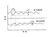
- FIG. 6 is a diagram showing an example of a change in temperature measured by the temperature measuring device 20 when a wind of a constant wind speed is applied to the optical fiber 10.
- first measurement unit only the first coating layer 12 of the optical fiber 10 (hereinafter referred to as “first measurement unit”) and the portion where the second coating layer 13 is disposed (hereinafter referred to as “second measurement unit”).
- first measurement unit only the first coating layer 12 of the optical fiber 10
- second measurement unit the portion where the second coating layer 13 is disposed
- an air flow is generated in the room by an air conditioner.
- the temperature of the wind generated by the air conditioner is not constant and has a temperature fluctuation of about ⁇ 0.5 ° C.
- the temperature measured by the temperature measuring device 20 changes with time in both the first measurement unit and the second measurement unit due to fluctuations in the temperature of the wind.
- the temperature change in the second measurement unit is smaller than the temperature change in the first measurement unit, and the time ⁇ t determined by the thermal conductivity and the heat capacity of the second coating layer 13 is delayed.
- the second coating layer 13 has a function as a low-frequency transmission filter whose characteristics are determined by its thermal conductivity and heat capacity.
- the temperature fluctuation in the second measurement unit measured by the temperature measuring device 20 shows basically the same change as the temperature fluctuation in the first measurement unit.
- the higher the wind speed the more the averaging proceeds in the temperature transmission process, so the ratio of the temperature fluctuation width ⁇ T2 in the second measurement section to the temperature fluctuation width ⁇ T1 in the first measurement section becomes smaller. Therefore, the wind speed can be obtained from the ratio ( ⁇ T2 / ⁇ T1) of the temperature fluctuation width ⁇ T1 in the first measurement unit and the temperature fluctuation width ⁇ T2 in the second measurement unit.
- ⁇ T2 is obtained after the delay time is obtained and the phase difference is set to 0. It is preferable to calculate the value of / ⁇ T1.
- FIG. 7 is a diagram illustrating an example of a method for calculating the delay time ⁇ t between the temperature fluctuation in the first measurement unit and the temperature fluctuation in the second measurement unit.
- the temperature fluctuation in the first measurement unit is a function f 1 (t) of time t
- the temperature fluctuation in the second measurement unit is a function f 2 (t) of time t.
- ⁇ t is gradually changed from 0 to a larger value to calculate the value of f 1 (t + ⁇ t) ⁇ f 2 (t), and the time when the value becomes the minimum is set as the delay time ⁇ t. If the delay time ⁇ t is determined, the phase difference between the temperature fluctuation in the first measurement unit and the temperature fluctuation in the second measurement unit can be set to zero.
- FIG. 8 is a diagram showing the relationship between the ambient temperature and the wind speed on the horizontal axis and the value of ⁇ T2 / ⁇ T1 on the vertical axis.
- the reference wind speed is measured using a vane anemometer.
- the relationship between the value of ⁇ T2 / ⁇ T1 and the wind speed varies depending on the environmental temperature. Therefore, when the environmental temperature changes greatly, it is necessary to obtain the relationship between the value of ⁇ T2 / ⁇ T1 and the wind speed at a plurality of environmental temperatures in advance.
- the analysis device 25 stores a calibration table obtained from FIG.
- FIG. 9 is a flowchart showing an environment measurement method according to the present embodiment.
- the temperature measuring device 20 measures the temperature distribution in the length direction of the optical fiber 10. That is, laser light (laser pulse) is emitted from the laser light source 21 at regular time intervals. Thereafter, the photodetector 23 extracts the Stokes light and the anti-Stokes light from the backscattered light generated in the optical fiber 10, and outputs detected values of these light amounts to the data processing unit 24. The data processing unit 24 obtains the temperature distribution in the length direction of the optical fiber 10 from the detected values of the amount of Stokes light and anti-Stokes light, and outputs the result to the analyzer 25 as needed.
- laser light laser pulse
- the photodetector 23 extracts the Stokes light and the anti-Stokes light from the backscattered light generated in the optical fiber 10, and outputs detected values of these light amounts to the data processing unit 24.
- the data processing unit 24 obtains the temperature distribution in the length direction of the optical fiber 10 from the detected values of the amount of Stokes light and anti-Stokes light, and outputs the result to the
- step S ⁇ b> 12 the analysis device 25 extracts the temperature change with time in the first measurement unit and the temperature change with time in the second measurement unit from the temperature distribution output from the data processing unit 24. To do. Then, the phase change of these temperature changes is analyzed to obtain the delay time ⁇ t, and the phase difference between the temperature change in the first measurement unit and the temperature change in the second measurement unit is set to zero. Further, the analysis device 25 calculates the average value of the temperature change with time in the first measurement unit and sets it as the environmental temperature. The average value of the change with time in the second measurement unit may be calculated as the environmental temperature, or the average value of the change with time in both the first measurement unit and the second measurement unit may be calculated to calculate the environmental temperature. It is good.
- step S13 the process proceeds to step S13, and the analysis device 25 obtains the temperature fluctuation width ⁇ T1 in the first measurement unit and the temperature fluctuation width ⁇ T2 in the second measurement unit.
- step S14 the value of ⁇ T2 / ⁇ T1 is calculated.
- step S15 the analysis device 25 refers to the calibration table to obtain the wind speed from the value of ⁇ T2 / ⁇ T1.
- the environmental temperature is 24 ° C.
- the analyzer 25 has only a calibration table at 20 ° C. and a calibration table at 30 ° C.
- the analysis device 25 calculates the wind speed at 24 ° C. by interpolating the wind speed obtained from the calibration table at 20 ° C. and the wind speed obtained from the calibration table at 30 ° C.
- the wind speed obtained from the calibration table at the temperature closest to the environmental temperature (in this case, the calibration table at 20 ° C.) is adopted, and the interpolation process may not be performed. . In this way, the temperature (environment temperature) and the wind speed for each measurement location are found.
- step S16 the analysis device 25 outputs the temperature and wind speed measurement results at each measurement location to a controller (not shown) that controls the air conditioning equipment.
- the controller controls the air conditioning equipment (air conditioners and fans installed at various locations in the office building) based on the temperature and wind speed measurement results output from the analysis device 25 to optimize the air conditioning. Do.
- the temperature and wind speed (fluid speed) of a plurality of measurement locations can be measured simultaneously with a single optical fiber 10.
- a heating element is not required for measuring the wind speed, and no electric power to be supplied to the heating element is required. For this reason, the power consumption of the whole system can be reduced.
- the environmental measurement system according to the present embodiment is suitable for measuring temperatures and wind speeds at a large number of measurement points in facilities such as data centers, large-scale office buildings, and factories.
- the temperature distribution is measured by Raman scattered light (Stokes light and anti-Stokes light), but the temperature distribution can also be measured by Brillouin scattered light.
- a multimode graded index type quartz optical fiber (HFR-2Z-1: manufactured by Furukawa Electric Co., Ltd.) was used as an optical fiber as a sensor.
- the core wire 11 is coated with a polyurethane resin, and this polyurethane resin layer is used as the first coating layer 12.
- the diameter of the optical fiber (the outer diameter of the first coating layer 12) is 250 ⁇ m, and the diameter of the core wire 11 is 125 ⁇ m.
- a UV curable silicone resin varnish (X-31-2011-1: manufactured by Shin-Etsu Chemical Co., Ltd.) is coated around the optical fiber at a pitch of 2 m along the length of the optical fiber.
- the coating layer 13 was obtained.
- the thickness of the second coating layer 13 is 0.3 mm.
- the silicone resin varnish was cured by irradiating light (ultraviolet rays) of a high-pressure mercury lamp (160 W / cm) while sweeping the optical fiber at a speed of 1 m / min.
- the optical fiber having the first coating layer 12 and the second coating layer 13 was laid in a wind tunnel capable of sending a wind having a constant temperature and speed. Then, the end of the optical fiber was connected to a Raman scattered light measuring device (DTS800M: manufactured by SENSA Co.) serving as the temperature measuring device 20.
- DTS800M Raman scattered light measuring device
- a hot-wire anemometer was placed in the wind tunnel. And the wind speed setting value was changed from 1 m / s to 10 m / s, and the wind speed was measured with the hot-wire anemometer and the environmental measurement method according to the present embodiment.
- the temperature of the portion where only the first coating layer 12 and the portion where the second coating layer 13 is arranged is sampled every 10 seconds by the Raman scattered light measurement device. Recorded. And the temperature (environment temperature) of the wind was computed from the part only of the 1st coating layer 12 using the data.
- the ratio ( ⁇ T2 / ⁇ T1) of the temperature fluctuation width of the portion where only the first covering layer 12 and the portion where the second covering layer 13 is arranged is calculated, and the value is converted into the wind speed using FIG. .
- FIG. 10 is a diagram showing a correlation between the wind speed measurement value obtained by the environmental measurement method according to the present embodiment and the wind speed measurement value obtained by the hot-wire anemometer. As shown in FIG. 10, the error between the wind speed measured by the environmental measurement method of the present embodiment and the wind speed measured by the hot-wire anemometer is 10% or less, and it was confirmed that they almost coincided.
- the temperature measurement device 20 and the analysis device (computer) 25 consume power, and the power consumption when the environment measurement is performed using an optical fiber having a total length of 2 km is approximately. 200W or less.
- the second coating layer 13 is formed of a resin (polymer material), but the second coating layer 13 may be formed of a metal material or an inorganic material. Further, the second coating layer 13 may be formed using a composite of these materials. The heat capacity and thermal conductivity change depending on the material of the coating layer, and the characteristics of the optical fiber as a sensor can be adjusted.
- FIG. 11 is a block diagram illustrating an outline of an environment measurement system according to the second embodiment. 11, the same components as those in FIG. 1 are denoted by the same reference numerals, and detailed description thereof is omitted.
- a temperature measuring device 30 capable of connecting two optical fibers 32 and 33 is used.
- the temperature measuring device 30 used in the present embodiment has an optical switch 31, and the optical switch 31 controls the optical connection between the laser light source 21 and the beam splitter 22 and the optical fibers 32 and 33.
- the above-described Raman scattering measurement device (DTS800M: manufactured by SENSA) can optically switch between a plurality of optical fibers, a laser light source, and a beam splitter via an optical switch provided therein.
- a temperature measuring device having a plurality of sets of the laser light source 21, the beam splitter 22, and the photodetector 23 may be used.
- first optical fiber 32 connected to the temperature measuring device 30 is obtained by coating the periphery of the core wire 11 only with the first coating layer 12.
- first optical fiber 32 for example, the above-described multimode graded index type silica fiber (HFR-2Z-1: manufactured by Furukawa Electric Co., Ltd.) can be used.
- the other optical fiber 33 (hereinafter referred to as “second optical fiber”) 33 connected to the temperature measuring device 30 is doubled around the core wire 11 by the first coating layer 12 and the second coating layer 13. It is coated.
- the second optical fiber 33 for example, the same optical fiber as the first optical fiber 32 is coated with a foaming urethane resin (second coating layer 13) with a thickness of 0.2 mm. be able to.
- the second optical fiber 33 may have a single coating layer. In this case, it is necessary to use a coating layer having at least one of a heat capacity and a thermal conductivity different from that of the coating layer 12 of the first optical fiber 32. is there.
- the first optical fiber 32 and the second optical fiber 33 are laid in parallel and close to the measurement location in the facility.
- the distance between the first optical fiber 32 and the second optical fiber 33 is, for example, about 5 mm.
- laser light is incident on the first optical fiber 32 and the second optical fiber 33 from the temperature measuring device 30, respectively, and the temperature of the measurement location is measured by backscattered light.
- the second coating layer 13 is provided on the second optical fiber 33, the change over time in the temperature measured by the second optical fiber 33 is the temperature measured by the first optical fiber 32.
- the change width is small with respect to the change with time, and a time delay occurs.
- the process shown in the flowchart of FIG. 9 can be performed similarly to the first embodiment, and the environmental temperature and the wind speed at the measurement location can be measured.
- the temperature and wind speed (fluid speed) at a plurality of measurement locations can be measured simultaneously.
- the structure of a system is simple and the cost required for the system construction and the maintenance cost are reduced.
- a heating element is not required for measuring the wind speed, and no electric power is required to be supplied to the heating element. For this reason, power consumption can be reduced.
- FIG. 12 and 13 are diagrams showing an optical fiber of an environment measurement system according to another embodiment. 12 and 13, the same components as those in FIG. 2 are denoted by the same reference numerals, and detailed description thereof is omitted.
- the peripheral surface of the optical fiber serving as the sensor is smooth. However, as shown in FIGS. A groove may be formed.
- the optical fiber 41 shown in FIG. 12A is provided with a plurality of grooves 41 a extending in the length direction on the peripheral surface of the outermost coating layer 13.
- channel 41a in the surrounding surface of the coating layer 13 the surface area of the coating layer 13 increases, and the heat exchange between a wind and the coating layer 13 is performed rapidly.
- the optical fiber 42 shown in FIG. 12B has a plurality of grooves 42a extending in the circumferential direction on the peripheral surface of the outermost coating layer 13.
- the optical fiber serving as the sensor is laid so as to be orthogonal to the wind flow direction.
- the optical fiber 41 shown in FIG. 12A since the wind travels in a direction perpendicular to the groove, it is conceivable that the wind flow is disturbed.
- the optical fiber 42 shown in FIG. 12B since the wind flows in a direction parallel to the groove 42a, the disturbance of the wind flow is less than that in the optical fiber 41 shown in FIG.
- the characteristics as a sensor can be adjusted by forming a groove in the peripheral surface of the optical fiber.
- the coating layer 13 may contain bubbles as shown in FIGS. 13 (a) and 13 (b).
- An optical fiber 43 shown in FIG. 13A has a large number of independent bubbles in the coating layer 13
- an optical fiber 44 shown in FIG. 13B has a large number of continuous bubbles in the coating layer 13. is there.
Landscapes
- Physics & Mathematics (AREA)
- General Physics & Mathematics (AREA)
- Engineering & Computer Science (AREA)
- Aviation & Aerospace Engineering (AREA)
- Measuring Temperature Or Quantity Of Heat (AREA)
- Investigating Or Analyzing Materials Using Thermal Means (AREA)
Abstract
【課題】発熱体を必要とせず、且つ多数の場所の温度及び風速を比較的低コストで測定できる環境測定システム及び環境測定方法を提供する。 【解決手段】光ファイバ10に、被覆層が薄い第1の測定部と、被覆層が厚い第2の測定部とを設けておく。そして、第1の測定部と第2の測定部とを同一の測定場所に配置し、温度測定装置20から光ファイバ10にレーザ光を入射する。その後、温度測定装置20は、光ファイバ10内で発生する後方散乱光(ラマン散乱光)を受光して光ファイバ10の長さ方向の温度分布を取得する。解析装置25は、温度測定装置20から温度分布を入力し、第1の測定部における温度の変動の平均値を演算して測定場所の温度とする。また、第1の測定部における温度の変動幅と第2の測定部における温度の変動幅との比率を計算し、その結果を用いて風速を算出する。
Description
本発明は、工場やオフィスビル及びデータセンターなどにおいて温度及び風速を測定する環境測定システム及び環境測定方法に関する。
近年、地球温暖化の防止が急務の課題となっており、そのために社会のあらゆる場面で省エネルギー化が求められている。例えば工場や大規模オフィスビル及びインターネットデータセンターなど(以下、「オフィスビル等の施設」ともいう)では空調に用いる電力が膨大であり、空調設備自体の省電力化とともに空調の最適化が要求されている。
オフィスビル等の施設内の空調の最適化を図るためには、施設内の多数の場所で温度や風速を測定し、その結果に基づいて空調設備を制御することが好ましい。測定箇所が少ない場合は、それぞれの箇所に温度センサや風速センサを個別に設置することが考えられる。この種の用途に使用可能な温度センサには熱電対、白金測温抵抗体、サーミスタ及び膨張式温度計などがあり、風速センサには熱線式風速センサ、ベーン式(風車式)風速センサ及び超音波式風速センサなどがある。
しかし、このようなセンサを使用すると、測定箇所が多い場合は必要なセンサの数が多くなって、システム全体のコストが高くなる。また、センサの数が多くなるほどメンテナンスに要するコストも高くなる。そこで、光ファイバを温度センサとして用いる温度測定装置(以下、「光ファイバ温度測定装置」という)を使用して、オフィスビル等の施設内の温度を測定することが提案されている。
光ファイバ温度測定装置は、光ファイバ内にレーザ光を入射し、光ファイバ内で発生するラマン後方散乱光を検出して温度を測定するものであり、光ファイバの長さ方向に沿った温度分布を短時間で測定することができる。また、光ファイバを流速センサとする流速測定装置も提案されている。この種の流速測定装置では、光ファイバを発熱体で加熱し、温度変化に基づいて流体の流速を算出している。この種の流速測定装置を用いてオフィスビル等の施設内の風速を測定することが考えられる。
上述したように、従来の光ファイバを用いた流速測定装置では、発熱体により光ファイバを加熱している。このため、光ファイバとは別に、発熱体に電力を供給するための電源と配線とが必要になる。また、発熱体に供給する電力の分だけ消費電力が多くなるという欠点もある。
一観点によれば、被覆層の熱容量及び熱伝導率の少なくとも一方が異なる第1の測定部及び第2の測定部を備えた光ファイバと、前記光ファイバに光を入射し、前記光ファイバから出射される後方散乱光を受光して前記光ファイバの長さ方向の温度分布を測定する温度測定装置と、前記温度測定装置から出力される温度分布の経時変化を解析して前記第1の測定部及び前記第2の測定部が配置された測定場所の温度と風速とを算出する解析装置とを有する環境測定システムが提供される。
上記一観点によれば、被覆層の熱容量及び熱伝導率の少なくとも一方が異なる第1の測定部及び第2の測定部を有する光ファイバを使用する。そして、第1の測定部及び第2の測定部を同一測定場所に配置し、温度測定装置により第1の測定部及び第2の測定部における温度を測定する。この場合、温度が変化すると、第1の測定部及び第2の測定部で検出される温度がいずれも変化するが、風の強さにより第1の測定部で検出される温度の変動幅と第2の測定部で検出される温度の変動幅とが異なる。このため、第1の測定部で検出される温度の変動幅と第2の測定部で検出される温度の変動幅との比率により、風速を算出することができる。また、測定場所の温度は、例えば第1の測定部又は第2の測定部で検出される温度の平均値により得られる。
上記一観点によれば、発熱体を使用することなく風速を測定することができる。また、例えば1本の光ファイバに第1の測定部及び第2の測定部をそれぞれ複数設けておくことにより、1本の光ファイバで多数の測定場所の温度と風速とを測定することができる。1本の光ファイバに第1の測定部及び第2の測定部を設ける替わりに、被覆層の熱容量及び熱伝導率の少なくとも一方が異なる2本の光ファイバを用いてもよい。
以下、実施形態について、添付の図面を参照して説明する。
(第1の実施形態)
図1は、第1の実施形態に係る環境測定システムの概要を示すブロック図、図2(a),(b)はいずれも光ファイバの断面図である。
図1は、第1の実施形態に係る環境測定システムの概要を示すブロック図、図2(a),(b)はいずれも光ファイバの断面図である。
図1に示すように、本実施形態に係る環境測定システムは、光ファイバ10と、温度測定装置20と、解析装置(コンピュータ)25とを有している。
光ファイバ10は、レーザ光が伝搬する芯線11と、芯線11を被覆する第1の被覆層12と、光ファイバ10の長さ方向の所定の位置に配置されて第1の被覆層12を被覆する第2の被覆層13とを有する。図2(a)は第1の被覆層12が露出した部分の断面を示し、図2(b)は第2の被覆層13が配置された部分の断面を示している。これらの図2(a),(b)に示すように、芯線11は、コア11aと、コア11aの周囲に配置されたクラッド11bとを有し、コア11aとクラッド11bとの屈折率の差により光をコア11a内に閉じ込めて伝送する。
第1の被覆層12は例えばポリウレタン等の高分子樹脂からなり、芯線11全体を均一の厚さで被覆している。第2の被覆層13は、第1の被覆層12と同一の材料により形成されていてもよく、異なる材料により形成されていてもよい。要するに、光ファイバ10は、その長さ方向に沿って被覆層が厚い部分と被覆層が薄い部分とを有していればよい。本実施形態では、第2の被覆層13はシリコーン樹脂により形成されているものとする。
被覆層の厚さや材料により、被覆層の熱容量及び熱伝導率が変化する。従って、本実施形態で使用する光ファイバ10は、熱容量又は熱伝導率が相互に異なる2つの領域を有しているということができる。
後述するように、本実施形態では、第1の被覆層12のみの部分と第2の被覆層13が配置された部分とを同一の測定箇所に配置してその測定箇所の温度と風速とを測定する。測定箇所が1箇所の場合は第2の被覆層13を光ファイバ10の長さ方向の1箇所に配置すればよく、測定箇所が複数の場合は第2の被覆層13を光ファイバ10の長さ方向に沿って複数配置することが必要となる。
温度測定装置20は、レーザ光源21と、ビームスプリッタ22と、光検出器23と、データ処理部24とを有している。光ファイバ10(芯線11)は、レーザ光源21及びビームスプリッタ22と光学的に接続されている。
レーザ光源21からは一定の時間間隔でレーザ光(レーザパルス)が出射される。レーザ光源21から出射されたレーザ光は、ビームスプリッタ22を透過して光ファイバ10(芯線11)内に進入し、光ファイバ10内を長さ方向に伝搬する。光ファイバ10内を伝搬する光の一部は、光ファイバ10(芯線11)を構成する分子により後方散乱される。後方散乱された光は、光ファイバ10を戻って光源側端部から出射し、ビームスプリッタ12により反射されて光検出器23に入力される。
光ファイバ10内で発生する後方散乱光には、図3に示すように、レイリー(Rayleigh)散乱光と、ブリルアン(Brillouin)散乱光と、ラマン(Raman)散乱光とが含まれる。レイリー散乱光は入射光と同一波長の光であり、ブリルアン散乱光及びラマン散乱光は入射波長からシフトした波長の光である。
ラマン散乱光には、入射光よりも長波長側にシフトしたストークス光と、入射光よりも短波長側にシフトした反ストークス光とがある。ストークス光及び反ストークス光のシフト量はレーザ光の波長や光ファイバ10(芯線11)を構成する物質等に依存するが、通常50nm程度である。また、ストークス光及び反ストークス光の強度はいずれも温度により変化するが、ストークス光は温度による変化量が小さく、反ストークス光は温度による変化量が大きい。すなわち、ストークス光は温度依存性が小さく、反ストークス光は温度依存性が大きいということができる。光検出器23は、後方散乱光からストークス光及び反ストークス光を分離してそれぞれの光量を検出する。
図4は、横軸に時間をとり、縦軸に光検出器23で検出される信号強度をとって、ラマン散乱光の強度の経時変化の一例を示す図である。光ファイバ10にレーザパルスを入射した直後から一定の間、光検出器23にはストークス光及び反ストークス光が検出される。光ファイバ10の全長にわたって温度が均一の場合、レーザパルスが光ファイバ10に入射した時点を基準とすると、信号強度は時間の経過とともに減少する。この場合、横軸の時間は光ファイバ10の光源側端部から後方散乱が発生した位置までの距離を示しており、信号強度の経時的な減少は光ファイバ10による光の減衰を示している。
光ファイバ10の長さ方向にわたって温度が均一でない場合、例えば長さ方向に沿って高温部及び低温部が存在する場合は、ストークス光及び反ストークス光の信号強度は一様に減衰するのではなく、図4に示すように信号強度の経時変化を示す曲線に山及び谷が現れる。図4において、ある時間tにおける反ストークス光の強度をI1、ストークス光の強度をI2とする。
図5は、図4に示すラマン散乱光の強度の経時変化を基にI1/I2比を時間毎に計算し、且つ図4の横軸(時間)を距離に換算し、縦軸(信号強度)を温度に換算した結果を示す図である。この図5に示すように、反ストークス光とストークス光との強度比(I1/I2)を計算することにより、光ファイバ10の長さ方向における温度分布を測定することができる。
反ストークス光とストークス光との強度比の計算はデータ処理部24により行われ、データ処理部24からは所定の時間毎に光ファイバ10の長さ方向の温度分布が出力される。解析装置25は、データ処理部24から出力された温度分布の経時的変化を解析して温度と風速(流体速度)とを算出する。
図6は、光ファイバ10に一定の風速の風を与えた場合に温度測定装置20で測定される温度の変化の例を示した図である。ここでは、光ファイバ10の第1の被覆層12のみの部分(以下、「第1の測定部」という)と第2の被覆層13が配置された部分(以下、「第2の測定部」という)とが、コイル状に巻かれた状態で同一の場所に配置されているものとする。また、室内には、空調機により空気の流れ(風)が生じているものとする。一般的に、空調機の設定温度を一定にしても、空調機により生じる風の温度は一定ではなく、±0.5℃程度の温度の揺らぎを有する。
図6に示すように、第1の測定部及び第2の測定部のいずれにおいても、風の温度の揺らぎを受けて、温度測定装置20で測定される温度は経時的な変化を示す。この場合、第1の測定部における温度変化に対し第2の測定部における温度変化は、変化の幅が小さく、且つ第2の被覆層13の熱伝導率と熱容量とで決まる時間Δtの遅延が生じる。第2の被覆層13は、その熱伝導率と熱容量とで特性が決まる低周波透過フィルタとしての機能を有するということができる。
遅延や温度変化の幅の違いはあるものの、温度測定装置20で測定される第2の測定部における温度揺らぎは、第1の測定部における温度揺らぎと基本的に同じ変化を示す。ここで、風速が速いほど、温度の伝達過程で平均化が進むため、第1の測定部における温度揺らぎ幅ΔT1に対する第2の測定部における温度揺らぎ幅ΔT2の割合が小さくなる。従って、第1の測定部における温度揺らぎ幅ΔT1と第2の測定部における温度揺らぎ幅ΔT2との比率(ΔT2/ΔT1)から、風速を求めることができる。
但し、前述したように、第1の測定部における温度揺らぎと第2の測定部における温度揺らぎとの間には遅延(位相差)があるため、遅延時間を求めて位相差を0としてからΔT2/ΔT1の値を計算することが好ましい。
図7は、第1の測定部における温度揺らぎと第2の測定部における温度揺らぎとの間の遅延時間Δtの算出方法の一例を示す図である。この図7に示すように、第1の測定部における温度揺らぎを時間tの関数f1(t)とし、第2の測定部における温度揺らぎを時間tの関数f2(t)とする。そして、Δtを0から少しずつ大きな値に変更してf1(t+Δt)-f2(t)の値を計算し、その値が最小となる時間を遅延時間Δtとする。遅延時間Δtが決定すれば、第1の測定部における温度揺らぎと第2の測定部における温度揺らぎとの位相差を0とすることができる。
図8は、横軸に風速をとり、縦軸にΔT2/ΔT1の値をとって、両者の関係を環境温度毎に示す図である。但し、基準となる風速はベーン式風速計を用いて測定している。この図8に示すように、ΔT2/ΔT1の値と風速との関係は環境温度によって変化する。従って、環境温度が大きく変化する場合は、予め複数の環境温度でΔT2/ΔT1の値と風速との関係を求めておくことが必要となる。ここでは、解析装置25には図8から求めた校正テーブル、すなわち環境温度毎のΔT2/ΔT1の値と風速との関係を示すテーブルが記憶されているものとする。なお、環境温度毎にΔT2/ΔT1の値と風速との関係を示す関係式(計算式)を求め、その関係式を解析装置25に記憶しておいてもよい。
図9は、本実施形態に係る環境測定方法を示すフローチャートである。
まず、ステップS11において、温度測定装置20は、光ファイバ10の長さ方向の温度分布を測定する。すなわち、レーザ光源21から一定の時間間隔でレーザ光(レーザパルス)を出射する。その後、光検出器23は、光ファイバ10内で発生した後方散乱光からストークス光及び反ストークス光を抽出し、それらの光量の検出値をデータ処理部24に出力する。データ処理部24は、ストークス光及び反ストークス光の光量の検出値から光ファイバ10の長さ方向の温度分布を求め、その結果を解析装置25に随時出力する。
次に、ステップS12に移行し、解析装置25は、データ処理部24から出力される温度分布から、第1の測定部における温度の経時変化と第2の測定部における温度の経時変化とを抽出する。そして、それらの温度の経時変化を位相分析して遅延時間Δtを求め、第1の測定部における温度の経時変化と第2の測定部における温度の経時変化との位相差を0とする。また、解析装置25は、第1の測定部における温度の経時変化の平均値を算出して、環境温度とする。なお、第2の測定部における温度の経時変化の平均値を算出して環境温度としてもよく、第1の測定部及び第2の測定部の両方における経時変化の平均値を算出して環境温度としてもよい。
次に、ステップS13に移行し、解析装置25は、第1の測定部における温度変動幅ΔT1と第2の測定部における温度変動幅ΔT2とを求める。そして、ステップS14において、ΔT2/ΔT1の値を算出する。
次に、ステップS15に移行し、解析装置25は校正テーブルを参照して、ΔT2/ΔT1の値から風速を求める。ここで、例えば環境温度が24℃であり、解析装置25内には20℃のときの校正テーブルと30℃のときの校正テーブルしかないとする。この場合、解析装置25は、20℃のときの校正テーブルから求めた風速と30℃のときの校正テーブルから求めた風速とを補間処理して、24℃のときの風速を算出する。なお、風速の精度がそれほど要求されない場合は、環境温度に最も近い温度の校正テーブル(上記の場合は20℃のときの校正テーブル)で求めた風速を採用し、補間処理を行わなくてもよい。このようにして、測定箇所毎の温度(環境温度)と風速とが判明する。
次いで、ステップS16に移行し、解析装置25は、各測定箇所における温度及び風速の測定結果を、空調設備をコントロールするコントローラ(図示せず)に出力する。コントローラは、解析装置25から出力された温度及び風速の測定結果を基に空調設備(空調機及びオフィスビル等の施設内の各所に設置されたファン等)をコントロールして、空調の最適化を行う。
本実施形態では、1本の光ファイバ10で複数(例えば100以上)の測定箇所の温度と風速(流体の速度)とを同時に測定することができる。このため、測定箇所毎に温度センサ及び風速センサを個別に配置するシステムに比べてシステムの構成が簡単であり、システムを構築するためのコスト及びメンテナンスに要するコストが低減される。また、本実施形態では、風速の測定に発熱体が必要ではなく、発熱体に供給する電力も必要ない。このため、システム全体の消費電力が少なくてすむ。これらの理由により、本実施形態に係る環境測定システムは、データセンターや大規模オフィスビル及び工場などの施設内の多数の測定箇所の温度及び風速の測定に好適である。
なお、本実施形態ではラマン散乱光(ストークス光及び反ストークス光)により温度分布を測定するものとしているが、ブリルアン散乱光により温度分布を測定することも可能である。
以下、本実施形態に係る環境測定方法により温度と風速とを実際に測定した結果について説明する。
センサとなる光ファイバには、マルチモード・グレーデッドインデックス型石英光ファイバ(HFR-2Z-1:古河電気工業株式会社製)を使用した。この光ファイバは芯線11をポリウレタン樹脂で被覆したものであり、このポリウレタン樹脂の層を第1の被覆層12とした。光ファイバの直径(第1の被覆層12の外径)は250μm、芯線11の直径は125μmである。
この光ファイバの周囲に、紫外線硬化型シリコーン樹脂ワニス(X-31-2011-1:信越化学工業株式会社製)を光ファイバの長さ方向に沿って1mずつ2mのピッチでコーティングし、第2の被覆層13とした。この第2の被覆層13の厚さは0.3mmである。なお、シリコーン樹脂ワニスを光ファイバに塗布した後、当該光ファイバを1m/minの速度で掃引しながら高圧水銀灯(160W/cm)の光(紫外線)を照射してシリコーン樹脂ワニスを硬化させた。
この第1の被覆層12及び第2の被覆層13を有する光ファイバを、温度及び速度が一定の風を送ることが可能な風洞内に敷設した。そして、その光ファイバの終端を温度測定装置20となるラマン散乱光測定装置(DTS800M:SENSA社製)に接続した。
また、風洞内には、熱線式風速計も配置した。そして、風洞の風速設定値を1m/sから10m/sまで変化させて、熱線式風速計及び本実施形態に係る環境測定方法により風速を測定した。なお、本実施形態に係る環境測定方法では、ラマン散乱光測定装置により、第1の被覆層12のみの部分と第2の被覆層13が配置された部分の温度を10秒毎にサンプリングして記録した。そして、そのデータを使用して第1の被覆層12のみの部分から風の温度(環境温度)を算出した。また、第1の被覆層12のみの部分と第2の被覆層13が配置された部分の温度揺らぎ幅の比率(ΔT2/ΔT1)を算出し、その値を図8を用いて風速に換算した。
図10は、本実施形態に係る環境測定方法による風速測定値と熱線式風速計による風速測定値との相関を示す図である。この図10に示すように、本実施形態の環境測定方法により測定した風速と熱線式風速計による測定した風速との誤差は10%以下であり、ほぼ一致していることが確認された。
本実施形態に係る環境測定方法では、電力を消費するのは温度測定装置20及び解析装置(コンピュータ)25のみであり、全長2kmの光ファイバを用いて環境測定を行った場合の消費電力はおおよそ200W又はそれ以下である。
なお、本実施形態では第2の被覆層13を樹脂(高分子材料)により形成しているが、第2の被覆層13を金属材料又は無機材料などにより形成してもよい。また、これらの材料を複合化したものを用いて第2の被覆層13を形成してもよい。被覆層の材質により熱容量や熱伝導率が変化し、光ファイバのセンサとしての特性を調整することができる。
(第2の実施形態)
図11は、第2の実施形態に係る環境測定システムの概要を示すブロック図である。図11において、図1と同一物には同一符号を付して、その詳細な説明は省略する。
図11は、第2の実施形態に係る環境測定システムの概要を示すブロック図である。図11において、図1と同一物には同一符号を付して、その詳細な説明は省略する。
本実施形態においては、2本の光ファイバ32,33を接続可能な温度測定装置30を使用する。本実施形態において使用する温度測定装置30は、光スイッチ31を有しており、この光スイッチ31によりレーザ光源21及びビームスプリッタ22と光ファイバ32,33との間の光学的接続を制御することができる。例えば、前述したラマン散乱測定装置(DTS800M:SENSA社製)は、その内部に設けられた光スイッチを介して複数の光ファイバとレーザ光源及びビームスプリッタとの間を光学的に切替えることができる。なお、光スイッチ31により光接続を切り替える方式の温度測定装置30に替えて、レーザ光源21、ビームスプリッタ22及び光検出器23を複数組有する温度測定装置を使用してもよい。
温度測定装置30に接続される一方の光ファイバ(以下、「第1の光ファイバ」という)32は、芯線11の周囲を第1の被覆層12のみで被覆したものである。この第1の光ファイバ32として、例えば前述のマルチモード・グレーデッドインデックス型石英ファイバ(HFR-2Z-1:古河電気工業株式会社製)を使用することができる。
温度測定装置30に接続される他方の光ファイバ(以下、「第2の光ファイバ」という)33は、芯線11の周囲を第1の被覆層12と第2の被覆層13とにより2重に被覆したものである。この第2の光ファイバ33として、例えば第1の光ファイバ32と同一の光ファイバの周囲に発泡性ウレタン樹脂(第2の被覆層13)を0.2mmの厚さで被覆したものを使用することができる。なお、第2の光ファイバ33は被覆層が1層でもよく、その場合は第1の光ファイバ32の被覆層12に対し熱容量及び熱伝導率の少なくとも一方が異なる被覆層を用いることが必要である。
第1の光ファイバ32及び第2の光ファイバ33は、施設内の測定箇所に並行且つ近接して敷設する。第1の光ファイバ32と第2の光ファイバ33との間隔は、例えば5mm程度とする。そして、温度測定装置30から第1の光ファイ32及び第2の光ファイバ33にそれぞれレーザ光を入射し、後方散乱光により測定箇所の温度を測定する。この場合、第2の光ファイバ33には第2の被覆層13が設けられているため、第2の光ファイバ33で測定される温度の経時変化は第1の光ファイバ32で測定される温度の経時変化に対し変化の幅が小さく、且つ時間の遅れが生じる。このため、本実施形態においても、第1の実施形態と同様に図9のフローチャートに示す処理を実施して、測定箇所の環境温度及び風速を測定することができる。
本実施形態においては、2本の光ファイバが必要であるが、第1の実施形態と同様に、複数の測定箇所の温度と風速(流体の速度)とを同時に測定することができる。このため、測定箇所毎に温度センサ及び風速センサを個別に配置するシステムに比べてシステムの構成が簡単であり、システムを構築するためのコスト及びメンテナンスに要するコストが低減される。また、本実施形態においても、第1の実施形態と同様に、風速の測定に発熱体が必要ではなく、発熱体に供給する電力も必要ない。このため、消費電力が少なくてすむ。
(その他の実施形態)
図12,図13は、その他の実施形態に係る環境測定システムの光ファイバを示す図である。これらの図12,図13において、図2と同一物には同一符号を付して、その詳細な説明を省略する。
図12,図13は、その他の実施形態に係る環境測定システムの光ファイバを示す図である。これらの図12,図13において、図2と同一物には同一符号を付して、その詳細な説明を省略する。
前述の第1及び第2の実施形態では、いずれもセンサとなる光ファイバの周面が滑らかであるものとしたが、図12(a),(b)に示すように光ファイバの周面に溝を形成してもよい。
図12(a)に示す光ファイバ41は、その最外周の被覆層13の周面に、長さ方向に延びる複数の溝41aが設けられている。このように被覆層13の周面に溝41aを設けることにより被覆層13の表面積が増大し、風と被覆層13との間の熱交換が迅速に行われる。
図12(b)に示す光ファイバ42は、その最外周の被覆層13の周面に、周方向に延びる複数の溝42aが設けられている。センサとなる光ファイバは、風の流れ方向に対し直交するように敷設する。図12(a)に示す光ファイバ41では風が溝に直交する方向に進むため、風の流れに乱れが発生することが考えられる。これに対し、図12(b)に示す光ファイバ42では、溝42aに平行な方向に風が流れるため、風の流れの乱れが図12(a)に示す光ファイバ41よりも少なくなる。図12(a),(b)に示すように光ファイバの周面に溝を形成することで、センサとしての特性を調整することができる。
また、被覆層の熱特性(熱容量及び熱伝導率)を制御することを目的とし、図13(a),(b)に示すように被覆層13に気泡を含有するようにしてもよい。図13(a)に示す光ファイバ43は被覆層13に多数の独立した気泡を有するものであり、図13(b)に示す光ファイバ44は被覆層13に多数の連続した気泡を有するものである。
Claims (15)
- 被覆層の熱容量及び熱伝導率の少なくとも一方が異なる第1の測定部及び第2の測定部を備えた光ファイバと、
前記光ファイバに光を入射し、前記光ファイバから出射される後方散乱光を受光して前記光ファイバの長さ方向の温度分布を測定する温度測定装置と、
前記温度測定装置から出力される温度分布の経時変化を解析して前記第1の測定部及び前記第2の測定部が配置された測定場所の温度と風速とを算出する解析装置と
を有することを特徴とする環境測定システム。 - 前記光ファイバには、その長さ方向に沿って前記第1の測定部及び前記第2の測定部が複数設けられていることを特徴とする請求項1に記載の環境測定システム。
- 前記解析装置は、前記第1の測定部における温度の経時変化と前記第2の測定部における温度の経時変化との位相差を補正することを特徴とする請求項1又は2に記載の環境測定システム。
- 前記解析装置は、前記第1の測定部における温度の変動幅と前記第2の測定部における温度の変動幅との比率を算出することを特徴とする請求項1に記載の環境測定システム。
- 前記解析装置には、風速と、前記第1の測定部における温度の変動幅と前記第2の測定部における温度の変動幅との比率との関係が記憶されていることを特徴とする請求項4に記載の環境測定システム。
- 前記第1の測定部は第1の被覆層のみを有し、前記第2の測定部は前記第1の被覆層と該第1の被覆層の周囲に配置された第2の被覆層とを有することを特徴とする請求項1に記載の環境測定システム。
- 前記第1の被覆層が高分子材料により形成され、前記第2の被覆層が高分子材料、金属材料及び無機材料のいずれか、又はそれらの材料を複合した材料により形成されていることを特徴とする請求項6に記載の環境測定システム。
- 前記第2の被覆層の周面に溝が設けられていることを特徴とする請求項6に記載の環境測定システム。
- 前記第2の被覆層内に気泡が設けられていることを特徴とする請求項6に記載の環境測定システム。
- 被覆層の熱容量及び熱伝導率の少なくとも一方が異なる第1の光ファイバ及び第2の光ファイバと、
前記第1の光ファイバ及び前記第2の光ファイバに光を入射し、前記第1の光ファイバ及び前記第2の光ファイバから出射される後方散乱光を受光して前記第1の光ファイバ及び前記第2の光ファイバの長さ方向の温度分布を測定する温度測定装置と、
前記温度測定装置から出力される温度分布の経時変化を解析して前記第1の光ファイバ及び前記第2の光ファイバが配置された測定場所の温度と風速とを算出する解析装置と
を有することを特徴とする環境測定システム。 - 前記解析装置は、前記第1の光ファイバのうち前記測定場所に配置された部分における温度の経時変化と、前記第2の光ファイバのうち前記測定場所に配置された部分における温度の経時変化との位相差を補正することを特徴とする請求項10に記載の環境測定システム。
- 前記解析装置は、前記第1の光ファイバのうち前記測定場所に配置された部分における温度の変動幅と、前記第2の光ファイバのうち前記測定場所に配置された部分における温度の変動幅との比率を算出することを特徴とする請求項10又は11に記載の環境測定システム。
- 前記解析装置には、風速と、前記第1の光ファイバにおける温度の変動幅と前記第2の光ファイバにおける温度の変動幅との比率との関係が記憶されていることを特徴とする請求項10に記載の環境測定システム。
- 同一の測定場所に光ファイバの第1の測定部及び第2の測定部を配置する工程と、
前記光ファイバに光を入射し、前記光ファイバから出射される後方散乱光から前記第1の測定部における温度の経時変化と前記第2の測定部における温度の経時変化とを測定する工程と、
前記第1の測定部における温度の経時変化及び前記第2の測定部における温度の経時変化の少なくとも一方から前記測定場所の温度を算出する工程と、
前記第1の測定部における温度の変動幅と前記第2の測定部における温度の変動幅との比率から前記測定場所における風速を算出する工程とを有し、
前記光ファイバの前記第1の測定部及び前記第2の測定部は、被覆層の熱容量及び熱伝導率の少なくとも一方が異なることを特徴とする環境測定方法。 - 前記第1の測定部における温度の経時変化と前記第2の測定部における温度の経時変化とを測定する工程と前記風速を求める工程との間に、
前記第1の測定部における温度の経時変化と前記第2の測定部における温度の経時変化との位相差を補正する工程を有することを特徴とする請求項14に記載の環境測定方法。
Priority Applications (3)
| Application Number | Priority Date | Filing Date | Title |
|---|---|---|---|
| JP2012501567A JP5435122B2 (ja) | 2010-02-24 | 2010-02-24 | 環境測定システム及び環境測定方法 |
| PCT/JP2010/052817 WO2011104828A1 (ja) | 2010-02-24 | 2010-02-24 | 環境測定システム及び環境測定方法 |
| US13/564,131 US8740454B2 (en) | 2010-02-24 | 2012-08-01 | Environmental measurement system and environmental measurement method |
Applications Claiming Priority (1)
| Application Number | Priority Date | Filing Date | Title |
|---|---|---|---|
| PCT/JP2010/052817 WO2011104828A1 (ja) | 2010-02-24 | 2010-02-24 | 環境測定システム及び環境測定方法 |
Related Child Applications (1)
| Application Number | Title | Priority Date | Filing Date |
|---|---|---|---|
| US13/564,131 Continuation US8740454B2 (en) | 2010-02-24 | 2012-08-01 | Environmental measurement system and environmental measurement method |
Publications (1)
| Publication Number | Publication Date |
|---|---|
| WO2011104828A1 true WO2011104828A1 (ja) | 2011-09-01 |
Family
ID=44506275
Family Applications (1)
| Application Number | Title | Priority Date | Filing Date |
|---|---|---|---|
| PCT/JP2010/052817 Ceased WO2011104828A1 (ja) | 2010-02-24 | 2010-02-24 | 環境測定システム及び環境測定方法 |
Country Status (3)
| Country | Link |
|---|---|
| US (1) | US8740454B2 (ja) |
| JP (1) | JP5435122B2 (ja) |
| WO (1) | WO2011104828A1 (ja) |
Cited By (8)
| Publication number | Priority date | Publication date | Assignee | Title |
|---|---|---|---|---|
| CN102890160A (zh) * | 2012-10-19 | 2013-01-23 | 华锐风电科技(集团)股份有限公司 | 测风设备的检测方法和装置 |
| JP2013130483A (ja) * | 2011-12-21 | 2013-07-04 | Fujitsu Ltd | 測定装置及び測定方法 |
| CN104769441A (zh) * | 2012-04-16 | 2015-07-08 | 爱普西莱恩公司 | 包括多个激光源的风速测定装置 |
| JP2016138824A (ja) * | 2015-01-28 | 2016-08-04 | 株式会社日立製作所 | 光ファイバ水位計測装置及び水位計測方法 |
| JP2019160164A (ja) * | 2018-03-16 | 2019-09-19 | 三菱電機インフォメーションネットワーク株式会社 | 送信装置、受信装置、送信方法、受信方法、送信プログラム及び受信プログラム |
| JP2021169975A (ja) * | 2020-04-16 | 2021-10-28 | マツダ株式会社 | 光ファイバを用いた流れ方向の計測システムおよび流れ方向の計測方法 |
| CN113916491A (zh) * | 2021-12-14 | 2022-01-11 | 中国空气动力研究与发展中心超高速空气动力研究所 | 一种用于辨识膨胀风洞加速段流动分区特性的试验装置 |
| JP2023138561A (ja) * | 2020-02-28 | 2023-10-02 | 日本電気株式会社 | 風速特定システム、風速特定装置、及び風速特定方法 |
Families Citing this family (8)
| Publication number | Priority date | Publication date | Assignee | Title |
|---|---|---|---|---|
| WO2011088393A2 (en) * | 2010-01-15 | 2011-07-21 | University Of Utah Research Foundation | Ultrasonic temperature measurement device |
| EP2899519B1 (en) * | 2014-01-24 | 2016-11-16 | Siemens Schweiz AG | Temperature sensing apparatus |
| JP6428336B2 (ja) * | 2015-02-12 | 2018-11-28 | 富士通株式会社 | 温度測定システム、温度測定方法及びプログラム |
| JP6428350B2 (ja) * | 2015-02-18 | 2018-11-28 | 富士通株式会社 | 温度測定システム、温度測定方法及びプログラム |
| CN105352624B (zh) * | 2015-10-09 | 2018-06-01 | 中国工程物理研究院流体物理研究所 | 全光纤式设计的器件微米尺度温度分布的测量方法及系统 |
| DE102017105285A1 (de) | 2017-03-13 | 2018-09-13 | fos4X GmbH | Temperatursensor und zugehöriges Herstellungsverfahren |
| US10690552B2 (en) * | 2017-12-06 | 2020-06-23 | Baker Hughes, A Ge Company, Llc | DTS performance improvement through variable mode path length averaging |
| US11585698B2 (en) * | 2019-09-16 | 2023-02-21 | Photon Control Inc. | Fiber optic temperature probe |
Citations (4)
| Publication number | Priority date | Publication date | Assignee | Title |
|---|---|---|---|---|
| JP3048784U (ja) * | 1997-11-11 | 1998-05-22 | 株式会社レイディック | 土中水分センサケーブル |
| JP2001194381A (ja) * | 2000-01-12 | 2001-07-19 | Foundation Of River & Basin Integrated Communications Japan | 光式流向計 |
| WO2008081720A1 (ja) * | 2006-12-28 | 2008-07-10 | Sumitomo Electric Industries, Ltd. | 流動体の物理量測定方法及び制御方法 |
| JP2009265083A (ja) * | 2008-04-02 | 2009-11-12 | Fujitsu Ltd | 温度計測方法、温度制御システム、風量測定装置及び発熱量測定装置 |
Family Cites Families (13)
| Publication number | Priority date | Publication date | Assignee | Title |
|---|---|---|---|---|
| US5004913A (en) * | 1982-08-06 | 1991-04-02 | Marcos Kleinerman | Remote measurement of physical variables with fiber optic systems - methods, materials and devices |
| JPH0348784A (ja) | 1989-07-18 | 1991-03-01 | Fanuc Ltd | プリント板及びそのバーンイン方式 |
| JP2880836B2 (ja) | 1991-10-18 | 1999-04-12 | 株式会社東芝 | 測定装置 |
| JPH06174561A (ja) | 1992-12-08 | 1994-06-24 | Japan Energy Corp | 光ファイバセンサ |
| JP3048784B2 (ja) | 1993-05-14 | 2000-06-05 | 三洋電機株式会社 | 充電器及び電子機器 |
| US6856396B2 (en) * | 2001-10-10 | 2005-02-15 | Swan International Services Pty | Wind shear detection system |
| WO2004012994A2 (en) * | 2002-08-02 | 2004-02-12 | Ophir Corporation | Optical air data measurement systems and methods |
| GB2401430B (en) * | 2003-04-23 | 2005-09-21 | Sensor Highway Ltd | Fluid flow measurement |
| GB0411097D0 (en) * | 2004-05-19 | 2004-06-23 | Qinetiq Ltd | Laser radar device and method |
| EP2327876A1 (en) * | 2009-11-30 | 2011-06-01 | Lm Glasfiber A/S | Wind turbine blade provided with optical wind velocity measurement system |
| WO2011111178A1 (ja) * | 2010-03-10 | 2011-09-15 | 富士通株式会社 | 環境測定システム及び環境測定方法 |
| US20120161446A1 (en) * | 2010-12-28 | 2012-06-28 | Vestas Wind Systems A/S | Global wind farm surveillance systems using fiber optic sensors |
| US8908160B2 (en) * | 2011-12-23 | 2014-12-09 | Optical Air Data Systems, Llc | Optical air data system suite of sensors |
-
2010
- 2010-02-24 JP JP2012501567A patent/JP5435122B2/ja not_active Expired - Fee Related
- 2010-02-24 WO PCT/JP2010/052817 patent/WO2011104828A1/ja not_active Ceased
-
2012
- 2012-08-01 US US13/564,131 patent/US8740454B2/en active Active
Patent Citations (4)
| Publication number | Priority date | Publication date | Assignee | Title |
|---|---|---|---|---|
| JP3048784U (ja) * | 1997-11-11 | 1998-05-22 | 株式会社レイディック | 土中水分センサケーブル |
| JP2001194381A (ja) * | 2000-01-12 | 2001-07-19 | Foundation Of River & Basin Integrated Communications Japan | 光式流向計 |
| WO2008081720A1 (ja) * | 2006-12-28 | 2008-07-10 | Sumitomo Electric Industries, Ltd. | 流動体の物理量測定方法及び制御方法 |
| JP2009265083A (ja) * | 2008-04-02 | 2009-11-12 | Fujitsu Ltd | 温度計測方法、温度制御システム、風量測定装置及び発熱量測定装置 |
Cited By (12)
| Publication number | Priority date | Publication date | Assignee | Title |
|---|---|---|---|---|
| JP2013130483A (ja) * | 2011-12-21 | 2013-07-04 | Fujitsu Ltd | 測定装置及び測定方法 |
| CN104769441A (zh) * | 2012-04-16 | 2015-07-08 | 爱普西莱恩公司 | 包括多个激光源的风速测定装置 |
| CN102890160A (zh) * | 2012-10-19 | 2013-01-23 | 华锐风电科技(集团)股份有限公司 | 测风设备的检测方法和装置 |
| JP2016138824A (ja) * | 2015-01-28 | 2016-08-04 | 株式会社日立製作所 | 光ファイバ水位計測装置及び水位計測方法 |
| JP2019160164A (ja) * | 2018-03-16 | 2019-09-19 | 三菱電機インフォメーションネットワーク株式会社 | 送信装置、受信装置、送信方法、受信方法、送信プログラム及び受信プログラム |
| JP6998803B2 (ja) | 2018-03-16 | 2022-01-18 | 三菱電機インフォメーションネットワーク株式会社 | 送信装置、受信装置、送信方法、受信方法、送信プログラム及び受信プログラム |
| JP2023138561A (ja) * | 2020-02-28 | 2023-10-02 | 日本電気株式会社 | 風速特定システム、風速特定装置、及び風速特定方法 |
| JP7552808B2 (ja) | 2020-02-28 | 2024-09-18 | 日本電気株式会社 | 風速特定システム、風速特定装置、及び風速特定方法 |
| JP2021169975A (ja) * | 2020-04-16 | 2021-10-28 | マツダ株式会社 | 光ファイバを用いた流れ方向の計測システムおよび流れ方向の計測方法 |
| JP7484367B2 (ja) | 2020-04-16 | 2024-05-16 | マツダ株式会社 | 光ファイバを用いた流れ方向の計測システムおよび流れ方向の計測方法 |
| CN113916491A (zh) * | 2021-12-14 | 2022-01-11 | 中国空气动力研究与发展中心超高速空气动力研究所 | 一种用于辨识膨胀风洞加速段流动分区特性的试验装置 |
| CN113916491B (zh) * | 2021-12-14 | 2022-10-21 | 中国空气动力研究与发展中心超高速空气动力研究所 | 一种用于辨识膨胀风洞加速段流动分区特性的试验装置 |
Also Published As
| Publication number | Publication date |
|---|---|
| US20120307861A1 (en) | 2012-12-06 |
| US8740454B2 (en) | 2014-06-03 |
| JPWO2011104828A1 (ja) | 2013-06-17 |
| JP5435122B2 (ja) | 2014-03-05 |
Similar Documents
| Publication | Publication Date | Title |
|---|---|---|
| JP5435122B2 (ja) | 環境測定システム及び環境測定方法 | |
| KR20120012426A (ko) | 이산화탄소 순도 센서 패키지, 이산화탄소 순도 측정 시스템 및 다-지점 이산화탄소 순도 측정 시스템 | |
| Cheng et al. | Experimental and simulation study on thermal gas flowmeter based on fiber Bragg grating coated with silver film | |
| US20120250722A1 (en) | Calibrated Fire Detection Cable | |
| CN103148956B (zh) | 一种基于涂覆微纳光纤进行温度测量的装置及方法 | |
| JP5228798B2 (ja) | 温度計測システム及び温度計測方法 | |
| JP5867618B2 (ja) | 異常検知システム及び異常検知方法 | |
| KR101462445B1 (ko) | 광 온도센서 측정 시스템 및 그 방법 | |
| CN103364112A (zh) | 一种用于分布式光纤测温系统的参数标定及自动校准方法 | |
| Chen et al. | Ultra-fast hygrometer based on U-shaped optical microfiber with nanoporous polyelectrolyte coating | |
| JP5673830B2 (ja) | 温度分布測定装置及び温度分布測定方法 | |
| JP5445668B2 (ja) | 環境測定システム及び環境測定方法 | |
| JP5825352B2 (ja) | 温度分布測定システム、温度分布測定装置及び温度分布測定方法 | |
| Terzis et al. | Improved accuracy in jet impingement heat transfer experiments considering the layer thicknesses of a triple thermochromic liquid crystal coating | |
| Klishina et al. | Method for simultaneous measurement of velocity and direction of fluid flow using fiber Bragg gratings | |
| Lönnermark et al. | Gas temperature measurements using fibre Bragg grating during fire experiments in a tunnel | |
| CN115931042A (zh) | 一种基于光纤传感的配电房环境监测方法和系统 | |
| US20140352443A1 (en) | Pipe wall thickness measurement | |
| Waluyo et al. | Testing and development of plastic optical fiber as humidity and temperature sensor | |
| Huang et al. | A Quasi-Distributed Fiber-Optic Temperature Sensor With a Resolution of 0.07$^{\circ} $ C Based on Fresnel Reflection | |
| JP6003296B2 (ja) | 湿度検出装置及び空調システム | |
| Brüne et al. | Temperature sensing in underground facilities by Raman optical frequency domain reflectometry using fiber-optic communication cables | |
| Li et al. | Relative humidity sensor based on photonic crystal fiber with tapered and filled in polymer | |
| CN116086642B (zh) | 一种基于激光吸收光谱的分布式光纤温度传感系统 | |
| Hussain et al. | Intensity-based humidity sensor through surface etching of POF by femtosecond laser |
Legal Events
| Date | Code | Title | Description |
|---|---|---|---|
| 121 | Ep: the epo has been informed by wipo that ep was designated in this application |
Ref document number: 10846494 Country of ref document: EP Kind code of ref document: A1 |
|
| WWE | Wipo information: entry into national phase |
Ref document number: 2012501567 Country of ref document: JP |
|
| NENP | Non-entry into the national phase |
Ref country code: DE |
|
| 122 | Ep: pct application non-entry in european phase |
Ref document number: 10846494 Country of ref document: EP Kind code of ref document: A1 |