WO2011102466A1 - 太陽電池用封止剤及びこれを用いた太陽電池 - Google Patents
太陽電池用封止剤及びこれを用いた太陽電池 Download PDFInfo
- Publication number
- WO2011102466A1 WO2011102466A1 PCT/JP2011/053515 JP2011053515W WO2011102466A1 WO 2011102466 A1 WO2011102466 A1 WO 2011102466A1 JP 2011053515 W JP2011053515 W JP 2011053515W WO 2011102466 A1 WO2011102466 A1 WO 2011102466A1
- Authority
- WO
- WIPO (PCT)
- Prior art keywords
- solar cell
- light
- photoelectric conversion
- wavelength
- fluorescent material
- Prior art date
- Legal status (The legal status is an assumption and is not a legal conclusion. Google has not performed a legal analysis and makes no representation as to the accuracy of the status listed.)
- Ceased
Links
Images




Classifications
-
- H—ELECTRICITY
- H10—SEMICONDUCTOR DEVICES; ELECTRIC SOLID-STATE DEVICES NOT OTHERWISE PROVIDED FOR
- H10F—INORGANIC SEMICONDUCTOR DEVICES SENSITIVE TO INFRARED RADIATION, LIGHT, ELECTROMAGNETIC RADIATION OF SHORTER WAVELENGTH OR CORPUSCULAR RADIATION
- H10F77/00—Constructional details of devices covered by this subclass
- H10F77/40—Optical elements or arrangements
- H10F77/42—Optical elements or arrangements directly associated or integrated with photovoltaic cells, e.g. light-reflecting means or light-concentrating means
- H10F77/45—Wavelength conversion means, e.g. by using luminescent material, fluorescent concentrators or up-conversion arrangements
-
- B—PERFORMING OPERATIONS; TRANSPORTING
- B32—LAYERED PRODUCTS
- B32B—LAYERED PRODUCTS, i.e. PRODUCTS BUILT-UP OF STRATA OF FLAT OR NON-FLAT, e.g. CELLULAR OR HONEYCOMB, FORM
- B32B17/00—Layered products essentially comprising sheet glass, or glass, slag, or like fibres
- B32B17/06—Layered products essentially comprising sheet glass, or glass, slag, or like fibres comprising glass as the main or only constituent of a layer, next to another layer of a specific material
- B32B17/10—Layered products essentially comprising sheet glass, or glass, slag, or like fibres comprising glass as the main or only constituent of a layer, next to another layer of a specific material of synthetic resin
- B32B17/10005—Layered products essentially comprising sheet glass, or glass, slag, or like fibres comprising glass as the main or only constituent of a layer, next to another layer of a specific material of synthetic resin laminated safety glass or glazing
- B32B17/10009—Layered products essentially comprising sheet glass, or glass, slag, or like fibres comprising glass as the main or only constituent of a layer, next to another layer of a specific material of synthetic resin laminated safety glass or glazing characterized by the number, the constitution or treatment of glass sheets
- B32B17/10036—Layered products essentially comprising sheet glass, or glass, slag, or like fibres comprising glass as the main or only constituent of a layer, next to another layer of a specific material of synthetic resin laminated safety glass or glazing characterized by the number, the constitution or treatment of glass sheets comprising two outer glass sheets
-
- B—PERFORMING OPERATIONS; TRANSPORTING
- B32—LAYERED PRODUCTS
- B32B—LAYERED PRODUCTS, i.e. PRODUCTS BUILT-UP OF STRATA OF FLAT OR NON-FLAT, e.g. CELLULAR OR HONEYCOMB, FORM
- B32B17/00—Layered products essentially comprising sheet glass, or glass, slag, or like fibres
- B32B17/06—Layered products essentially comprising sheet glass, or glass, slag, or like fibres comprising glass as the main or only constituent of a layer, next to another layer of a specific material
- B32B17/10—Layered products essentially comprising sheet glass, or glass, slag, or like fibres comprising glass as the main or only constituent of a layer, next to another layer of a specific material of synthetic resin
- B32B17/10005—Layered products essentially comprising sheet glass, or glass, slag, or like fibres comprising glass as the main or only constituent of a layer, next to another layer of a specific material of synthetic resin laminated safety glass or glazing
- B32B17/1055—Layered products essentially comprising sheet glass, or glass, slag, or like fibres comprising glass as the main or only constituent of a layer, next to another layer of a specific material of synthetic resin laminated safety glass or glazing characterized by the resin layer, i.e. interlayer
-
- B—PERFORMING OPERATIONS; TRANSPORTING
- B32—LAYERED PRODUCTS
- B32B—LAYERED PRODUCTS, i.e. PRODUCTS BUILT-UP OF STRATA OF FLAT OR NON-FLAT, e.g. CELLULAR OR HONEYCOMB, FORM
- B32B17/00—Layered products essentially comprising sheet glass, or glass, slag, or like fibres
- B32B17/06—Layered products essentially comprising sheet glass, or glass, slag, or like fibres comprising glass as the main or only constituent of a layer, next to another layer of a specific material
- B32B17/10—Layered products essentially comprising sheet glass, or glass, slag, or like fibres comprising glass as the main or only constituent of a layer, next to another layer of a specific material of synthetic resin
- B32B17/10005—Layered products essentially comprising sheet glass, or glass, slag, or like fibres comprising glass as the main or only constituent of a layer, next to another layer of a specific material of synthetic resin laminated safety glass or glazing
- B32B17/1055—Layered products essentially comprising sheet glass, or glass, slag, or like fibres comprising glass as the main or only constituent of a layer, next to another layer of a specific material of synthetic resin laminated safety glass or glazing characterized by the resin layer, i.e. interlayer
- B32B17/10651—Layered products essentially comprising sheet glass, or glass, slag, or like fibres comprising glass as the main or only constituent of a layer, next to another layer of a specific material of synthetic resin laminated safety glass or glazing characterized by the resin layer, i.e. interlayer comprising colorants, e.g. dyes or pigments
- B32B17/10669—Luminescent agents
-
- C—CHEMISTRY; METALLURGY
- C08—ORGANIC MACROMOLECULAR COMPOUNDS; THEIR PREPARATION OR CHEMICAL WORKING-UP; COMPOSITIONS BASED THEREON
- C08K—Use of inorganic or non-macromolecular organic substances as compounding ingredients
- C08K5/00—Use of organic ingredients
- C08K5/0008—Organic ingredients according to more than one of the "one dot" groups of C08K5/01 - C08K5/59
- C08K5/0041—Optical brightening agents, organic pigments
-
- C—CHEMISTRY; METALLURGY
- C08—ORGANIC MACROMOLECULAR COMPOUNDS; THEIR PREPARATION OR CHEMICAL WORKING-UP; COMPOSITIONS BASED THEREON
- C08L—COMPOSITIONS OF MACROMOLECULAR COMPOUNDS
- C08L53/00—Compositions of block copolymers containing at least one sequence of a polymer obtained by reactions only involving carbon-to-carbon unsaturated bonds; Compositions of derivatives of such polymers
- C08L53/02—Compositions of block copolymers containing at least one sequence of a polymer obtained by reactions only involving carbon-to-carbon unsaturated bonds; Compositions of derivatives of such polymers of vinyl-aromatic monomers and conjugated dienes
- C08L53/025—Compositions of block copolymers containing at least one sequence of a polymer obtained by reactions only involving carbon-to-carbon unsaturated bonds; Compositions of derivatives of such polymers of vinyl-aromatic monomers and conjugated dienes modified
-
- H—ELECTRICITY
- H10—SEMICONDUCTOR DEVICES; ELECTRIC SOLID-STATE DEVICES NOT OTHERWISE PROVIDED FOR
- H10F—INORGANIC SEMICONDUCTOR DEVICES SENSITIVE TO INFRARED RADIATION, LIGHT, ELECTROMAGNETIC RADIATION OF SHORTER WAVELENGTH OR CORPUSCULAR RADIATION
- H10F19/00—Integrated devices, or assemblies of multiple devices, comprising at least one photovoltaic cell covered by group H10F10/00, e.g. photovoltaic modules
- H10F19/80—Encapsulations or containers for integrated devices, or assemblies of multiple devices, having photovoltaic cells
- H10F19/804—Materials of encapsulations
-
- Y—GENERAL TAGGING OF NEW TECHNOLOGICAL DEVELOPMENTS; GENERAL TAGGING OF CROSS-SECTIONAL TECHNOLOGIES SPANNING OVER SEVERAL SECTIONS OF THE IPC; TECHNICAL SUBJECTS COVERED BY FORMER USPC CROSS-REFERENCE ART COLLECTIONS [XRACs] AND DIGESTS
- Y02—TECHNOLOGIES OR APPLICATIONS FOR MITIGATION OR ADAPTATION AGAINST CLIMATE CHANGE
- Y02E—REDUCTION OF GREENHOUSE GAS [GHG] EMISSIONS, RELATED TO ENERGY GENERATION, TRANSMISSION OR DISTRIBUTION
- Y02E10/00—Energy generation through renewable energy sources
- Y02E10/50—Photovoltaic [PV] energy
- Y02E10/52—PV systems with concentrators
Definitions
- the present invention relates to a solar cell encapsulant used for sealing solar cells and a solar cell using the same, and in particular, a novel solar cell encapsulant having a wavelength conversion effect and the solar cell. It is related with the solar cell which formed the sealing agent layer using the sealing agent for water.
- Solar cells that convert solar energy into electrical energy are attracting attention as clean renewable energy, replacing fossil fuels that emit greenhouse gases such as carbon dioxide. If solar cells are widely spread and can cover a part of electric power, the significance of environmental protection will be great.
- Patent Document 1 discloses a wavelength converter that absorbs light in a wavelength range with a low photoelectric conversion efficiency in the photoelectric conversion layer and emits light in a wavelength range with a high photoelectric conversion efficiency on the light incident side of the photoelectric conversion layer.
- a solar cell in which the layer is arranged in parallel with the photoelectric conversion layer is disclosed.
- the wavelength converter layer is formed by dispersing and mixing the wavelength converter fine powder in the transparent adhesive layer between the photoelectric conversion layer and the transparent protective cover. Forming.
- Patent Document 2 in a solar battery module including a solar battery cell that converts solar energy into electrical energy, the irradiated light is absorbed, and the absorbed light is converted into light having a longer wavelength.
- a solar cell module having a wavelength conversion layer for conversion is disclosed.
- the wavelength conversion layer is formed by being applied to the light receiving surface or is formed as a sealing material that protects the solar cells.
- Patent Document 3 discloses a solar cell in which a material containing an oxide fluorescent material is disposed in a path until light reaches the solar cell element.
- the oxide fluorescent material is capable of converting ultraviolet rays in a wavelength range of 200 to 400 nm into a wavelength range of 400 to 1000 nm.
- the present invention has been proposed in view of such a conventional situation, and provides a solar cell encapsulant capable of realizing higher photoelectric conversion efficiency than a conventional one and a solar cell using the same.
- the purpose is to do.
- the sealing agent for solar cells of the present invention is a sealing agent for solar cells in which a fluorescent material is dispersed or dissolved in a transparent resin, and the fluorescent material has a thickness of 350 nm to 400 nm. It absorbs more light in the wavelength range than light in the wavelength range exceeding 400 nm.
- the solar cell of the present invention is a solar cell in which a transparent protective glass is bonded to a solar cell having a photoelectric conversion layer via a sealant layer, and the sealant layer is made of a transparent resin.
- the fluorescent material is formed of a solar cell sealing agent in which a fluorescent material is dispersed or dissolved, and the fluorescent material contained in the sealing agent layer is made to emit light in a wavelength range of 350 nm to 400 nm from light in a wavelength range exceeding 400 nm. It is also characterized by absorbing a large amount.
- the fluorescent material used for the solar cell encapsulant functions as a wavelength converter, and as described in the above-mentioned Patent Documents 1 to 3, etc., the photoelectric conversion layer has a low photoelectric conversion efficiency. It is necessary to absorb light in the wavelength range and emit light in the long wavelength range with high photoelectric conversion efficiency. However, it is not always necessary that there is absorption in a short wavelength region (for example, a wavelength region of 400 nm or less). For example, even if there is absorption in a wavelength region of 400 nm or less, if there is absorption in a wavelength region longer than 400 nm, light necessary for photoelectric conversion in the photoelectric conversion layer will also be absorbed, and efficiency improvement by wavelength conversion Is offset and sufficient conversion efficiency cannot be realized.
- the encapsulant for solar cells of the present invention contains a fluorescent material that absorbs 350 nm to 400 nm of light more than light in the wavelength range exceeding 400 nm. Accordingly, light that cannot be absorbed by the photoelectric conversion layer can be efficiently photoelectrically converted to be usable, and thus effective conversion efficiency can be improved.
- the average particle diameter of the fluorescent material may be 20 nm or less, and the light transmittance at a wavelength of 600 nm to 800 nm of the encapsulant may be 90% or more.
- the encapsulant itself does not hinder the arrival of sunlight to the photoelectric conversion layer, and further improvement in photoelectric conversion efficiency can be realized.
- the particle size of the fluorescent material is 100 nm or more, the conversion efficiency may greatly decrease due to the scattering of sunlight, etc. This is a problem with solar cells that employ a wavelength conversion layer. It was one of the causes that were difficult to put into practical use.
- the sealing agent for solar cells of the present invention solves such a problem by setting the average particle diameter of the fluorescent material to 20 nm or less and the light transmittance at a wavelength of 600 to 800 nm of the sealing agent to 90% or more. It becomes possible.
- light in a wavelength range that could not directly contribute to photoelectric conversion can be effectively used for photoelectric conversion, for example, light that can be used in the photoelectric conversion layer of the solar cell can be expanded, It becomes possible to realize a solar cell having a good photoelectric conversion efficiency.
- FIG. 1 is a diagram showing absorption characteristics in a solar battery cell using single crystal silicon as a photoelectric conversion layer.
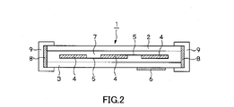
- FIG. 2 is a schematic cross-sectional view showing a schematic configuration of the solar cell.
- FIG. 3A is a diagram showing an absorption spectrum of fluorescent substance CdSe nanoparticles
- FIG. 3B is a figure showing an emission spectrum of fluorescent substance CdSe nanoparticles.
- FIG. 4A is a diagram showing an absorption spectrum of the fluorescent material DPhP-C4
- FIG. 4B is a diagram showing an emission spectrum of the fluorescent material DPhP-C4.
- FIG. 5A is a diagram showing an absorption spectrum of the fluorescent material ADS085, and FIG. 5B is a diagram showing an emission spectrum of the fluorescent material ADS085.
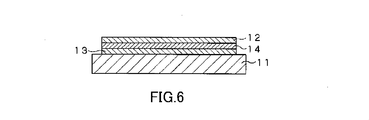
- FIG. 6 is a diagram showing an example of a sample cell used for evaluation, and is a schematic cross-sectional view of an evaluation cell using a solar battery cell using polycrystalline silicon as a photoelectric conversion layer.
- FIG. 7 is a diagram showing absorption characteristics in a solar battery cell using polycrystalline silicon as a photoelectric conversion layer.
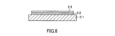
- FIG. 8 is a diagram showing an example of a sample cell used for evaluation, and is a schematic cross-sectional view of an evaluation cell using a solar battery cell using single crystal silicon as a photoelectric conversion layer.
- the present embodiment a solar cell encapsulant to which the present invention is applied and a solar cell using the same (hereinafter referred to as “the present embodiment”) will be described with reference to the drawings.
- the sealing agent for solar cells of this Embodiment is arrange
- a fluorescent substance that is a wavelength converter is dispersed or dissolved.
- Fluorescent material performs wavelength conversion on transmitted light.
- the fluorescent material needs to absorb light in a short wavelength region with low photoelectric conversion efficiency in the photoelectric conversion layer and emit light in a long wavelength region with high photoelectric conversion efficiency. is there.
- absorption is reduced with respect to light in a wavelength region of 500 nm or less, and in a wavelength region of 400 nm or less. For light, the absorption is further reduced.
- FIG. 1 is a diagram showing absorption characteristics (spectral sensitivity characteristics) of a sunlight spectrum in a solar battery cell using single crystal silicon as a photoelectric conversion layer.
- (a) is a spectral sensitivity characteristic when the solar battery cell is a normal cell
- (b) is a spectral sensitivity characteristic when the solar battery cell is a BSF (back surface field) type cell.
- BSF back surface field
- the absorption characteristics (spectral sensitivity characteristics) with respect to light in the wavelength region of 400 nm or less are extremely small in both cases where the solar battery cell is a normal type or a BSF type. For this reason, the solar cell of the present embodiment photoelectrically converts light in a wavelength region exceeding 400 nm.
- the fluorescent substance added to the solar cell encapsulant in the present embodiment is a fluorescent substance that absorbs light in a wavelength range of 400 nm or less and emits light in a wavelength range of more than 400 nm. Is preferred. By adding such a fluorescent substance to the sealing agent for solar cells, light that cannot be absorbed by the photoelectric conversion layer can be converted into light that can be absorbed by the photoelectric conversion layer.
- the fluorescent material preferably absorbs light in the wavelength range of 350 nm to 400 nm more than light in the wavelength range exceeding 400 nm. This is because even if light in a wavelength region of 400 nm or less is absorbed, if a large amount of light in a wavelength region exceeding 400 nm is absorbed, the total amount of light that can be used in the photoelectric conversion layer is reduced. By absorbing more light in the wavelength range of 350 nm to 400 nm than light in the wavelength range exceeding 400 nm, the light that can be used in the photoelectric conversion layer (direct light) is not reduced, and wavelength-converted light is also used. As a result, the total amount of light that can be used in the photoelectric conversion layer can be increased.
- the fluorescent substance is preferably a fluorescent substance having a peak in a wavelength region of 400 nm or less in the absorption spectrum and a peak in a wavelength region of 450 nm or more where the sensitivity of the solar cell is high in the emission spectrum.
- the difference in wavelength between the absorption peak and the emission peak, that is, the Stoke shift is preferably larger than 50 nm.
- the fluorescent material preferably has so-called absorption characteristics and is a so-called nanoparticle.
- the fluorescent material is preferably nanoparticles having an average particle size of 20 nm or less.
- the average particle size of a fluorescent material is generally larger than the wavelength of visible light and is larger than a submicron.
- the transparent resin that disperses or dissolves the fluorescent substance can be any resin material as long as it is a resin material that has sufficient transparency to transmit sunlight.
- silicone resin epoxy resin, polyurethane resin, vinyl Resin, styrene-based elastomer resin (styrene / ethylene-butylene / styrene (SEBS)), and the like.
- SEBS is excellent in transparency and handleability, and does not generate an acid unlike ethylene-vinyl acetate copolymer (EVA) and does not adversely affect the fluorescent material.
- EVA ethylene-vinyl acetate copolymer
- Particularly preferred as a transparent resin Particularly preferred as a transparent resin.
- the light transmittance of sunlight is 90% or more, particularly at a wavelength of 600 nm to 800 nm.
- the light transmittance can be 90% or more, and the light transmittance at a wavelength of 600 nm to 800 nm can be 95% or more.
- FIG. 2 is a diagram showing a configuration of the solar cell in the present embodiment.
- the solar cell 1 forms the sealing agent layer 7 which consists of the sealing agent for solar cells in this Embodiment between a pair of transparent protective glass 2 and 3, and seals the photovoltaic cell 4 which has a photoelectric converting layer. Configured by stopping.
- the solar cells 4 are electrically connected to each other by connection wirings 5, and power is taken out from a terminal box 6 provided on the back side.
- a known photoelectric conversion layer such as one using single crystal silicon, one using polycrystalline silicon, or one using amorphous (amorphous) silicon can be applied. Is possible.
- Sealant layer 7 is formed between transparent protective glass 2 and transparent protective glass 3.
- the outer peripheral portion of the sealant layer 7 is fixed to the frame 9 through a seal material 8. Thereby, sunlight passes through the transparent protective glass 2 and the sealant layer 7 on the front side and enters the solar battery cell 4.
- the solar cell 1 photoelectrically converts the fluorescent material in the encapsulant layer 7 by absorbing light in a wavelength region of 350 nm to 400 nm more than light in a wavelength region exceeding 400 nm.
- Wavelength-converted light can also be used without reducing the light available in the layer, and the total amount of light available in the photoelectric conversion layer can be increased.
- nanoparticles having an average particle diameter of 20 nm or less as the fluorescent material, light scattering can be suppressed and most of the incident sunlight can be used effectively. If the encapsulant layer 7 contains a fluorescent material having a normal particle size instead of nanoparticles, it is difficult to make the light transmittance 90% or more due to light scattering.
- the light transmittance of sunlight can be 90% or more by using nanoparticles having an average particle size of 20 nm or less as the fluorescent material and using SEBS as the transparent resin.
- the light transmittance at a wavelength of 600 nm to 800 nm can be 90% or more, and further 95% or more.
- the solar cell 1 can photoelectrically convert a sufficient amount of sunlight in the photoelectric conversion layer of the solar battery cell 4.
- the solar cell 1 absorbs light in a wavelength region with a low photoelectric conversion efficiency, emits light in a wavelength region with a high photoelectric conversion efficiency, and further has a light transmittance of 90% at a wavelength of 600 nm to 800 nm.
- the sealing agent layer 7 having excellent transparency is provided on the light incident side of the solar battery cell 4.
- Example 1 44 ⁇ l of fluorescent substance E560 (manufactured by EVIDOT) consisting of CdSe nanoparticles with an average particle diameter of 8 nm was added to 250 mg of SEBS, and 950 ⁇ l of toluene was added to prepare a sealant.
- EVIDOT fluorescent substance
- the absorption spectrum of the fluorescent substance E560 is shown in FIG. 3A.
- the emission spectrum of the fluorescent material E560 is shown in FIG. 3B.
- FIG. 3A in the absorption spectrum of the fluorescent substance E560, there is an absorption peak in the wavelength region of 350 nm or less, and the absorption in the wavelength region of 350 nm to 400 nm is larger than the absorption in the wavelength region exceeding 400 nm.
- FIG. 3B in the emission spectrum of the fluorescent material E560, there is a light emission peak in a wavelength region exceeding 500 nm (near the wavelength of 570 nm).
- a fluorescent substance DPhP-C4 for dyes shown in [Chemical Formula 1] below was prepared.
- a solar cell sealant was prepared by adding 194 ⁇ l of DPhP-C4 to 250 mg of SEBS and adding 800 ⁇ l of toluene.
- the absorption spectrum of this fluorescent substance DPhP-C4 is shown in FIG. 4A.
- the emission spectrum of the fluorescent substance DPhP-C4 is shown in FIG. 4B. As shown in FIG.
- the peak position of the emission is in a wavelength region of 500 nm or less (near the wavelength of 480 nm).
- a solar cell module was prototyped using the sealant prepared in Example 1 and Comparative Examples 1 and 2. Specifically, as shown in FIG. 6, sealing is performed by sandwiching a sealing agent between two transparent protective glasses 12 and 13 on the front surface of a solar cell module 11 including polycrystalline silicon as a photoelectric conversion layer. What formed the agent layer 14 was installed.
- the sealant layer 14 was formed by applying a sealant with a doctor blade and then sealing in an Ar atmosphere.
- the thickness of the sealing agent layer 14 was 60 ⁇ m.
- the size of the photovoltaic cell of the photovoltaic cell module 11 was set to 65 mm ⁇ 41 mm, and the sizes of the transparent protective glasses 12 and 13 were set to 70 mm ⁇ 70 mm.
- FIG. 7 shows the absorption characteristics (spectral sensitivity) of the solar cell module having such a configuration.
- curves (a) and (b) show the internal quantum efficiency as the spectral sensitivity of the solar cell module provided with SiN, which is polycrystalline silicon, as the photoelectric conversion layer, and the curve (c) The internal quantum efficiency of the solar cell module not equipped with SiN is shown.
- the internal quantum efficiency indicates how much the pair of electrons and holes generated by current emits light of the desired wavelength and recombines. The value is specified by the physical property of the material such as 1 and 1 is an ideal value.
- the internal quantum efficiency (curves (a) and (b)) of the solar cell module including SiN as a photoelectric conversion layer is a solar cell not including SiN. Is larger than the internal quantum efficiency (curve (c)). In a solar cell not provided with SiN, the internal quantum efficiency is drastically reduced particularly at 400 nm or less.
- the solar cell module has better absorption characteristics (spectral sensitivity) than the case where SiN is not provided by providing SiN which is polycrystalline silicon as a photoelectric conversion layer, particularly in a wavelength region of 400 nm or less. Can be realized.
- the solar battery cell of Example 1 obtained the best photoelectric conversion efficiency value.
- the fluorescent substance has an absorption peak in the wavelength range of 350 nm or less, and absorbs light in the wavelength range of 350 nm to 400 nm more than light in the wavelength range of more than 400 nm. It is possible to increase the total amount of light that can be used in the conversion layer, and it is possible to effectively use most of incident sunlight by suppressing light scattering by comprising CdSe nanoparticles having an average particle diameter of 8 nm. It was considered that good photoelectric conversion efficiency values were obtained.
- Fig. 8 shows the configuration of these prototype solar cell modules.
- the solar cell module shown in FIG. 8 has a structure in which a polyethylene terephthalate film 23 is bonded to the front surface of a solar cell module 21 using single crystal silicon as a photoelectric conversion layer via a sealant layer 22.
- the thickness of the sealant layer 22 and the thickness of the polyethylene terephthalate film 23 are both 25 ⁇ m.
- the size of the solar cell of the solar cell module 21 is 125 mm ⁇ 125 mm
- the size of the polyethylene terephthalate film 23 is 150 mm ⁇ 150 mm.
- the solar battery using the sealant of Example 1 has the best photoelectric conversion efficiency.
- a value was obtained.
- the fluorescent substance has an absorption peak in a wavelength region of 350 nm or less, and absorbs light in a wavelength region of 350 nm to 400 nm more than light in a wavelength region of more than 400 nm. It is possible to increase the total amount of light that can be used in the conversion layer, and it is possible to effectively use most of incident sunlight by suppressing light scattering by comprising CdSe nanoparticles having an average particle diameter of 8 nm. It was considered that good photoelectric conversion efficiency values were obtained.
Landscapes
- Chemical & Material Sciences (AREA)
- Health & Medical Sciences (AREA)
- Chemical Kinetics & Catalysis (AREA)
- Medicinal Chemistry (AREA)
- Polymers & Plastics (AREA)
- Organic Chemistry (AREA)
- Photovoltaic Devices (AREA)
- Sealing Material Composition (AREA)
- Electroluminescent Light Sources (AREA)
Abstract
光電変換効率を改善し得る太陽電池用封止剤を提供し、光電変換効率に優れ実用特性に優れた太陽電池を提供する。透明樹脂に蛍光物質が分散又は溶解されてなる太陽電池用封止剤において、蛍光物質は、350nm~400nmの波長域の光を400nmを越える波長域の光よりも多く吸収し、また、平均粒径が20nm以下である。この太陽電池用封止剤の波長600nm~800nmにおける光透過率は、90%以上である。
Description
本発明は、太陽電池セルの封止に使用する太陽電池用封止剤及びこれを用いた太陽電池に関するものであり、特に、波長変換効果を有する新規な太陽電池用封止剤及びこの太陽電池用封止剤を用いて封止剤層を形成した太陽電池に関する。
本出願は、日本国において2010年2月18日に出願された日本特許出願番号特願2010-33902を基礎として優先権を主張するものであり、この出願を参照することにより、本出願に援用される。
太陽光エネルギーを電気エネルギーに変換する太陽電池は、ニ酸化炭素等の温室効果ガスを排出する化石燃料に替わり、クリーンな再生可能エネルギーとして注目されている。太陽電池が一般に普及し、電力の一部を賄うことができれば、環境保全上その意義は大きいものとなる。
このような背景から、各方面で太陽電池の開発が進められている。しかしながら、太陽電池を実用化する上では、エネルギーの変換効率の悪さが大きな問題となっている。すなわち、太陽電池セルは、光電変換を行う際、太陽光のうちの一部の波長の光しか利用できず、このことが変換効率低下の要因となっている。
この問題を解決する方法の一つとして、太陽電池セルが利用できない短波長域の太陽光を、太陽電池セルが利用可能な長波長域の光に変換し、波長変換物質として蛍光物質等を用いる波長変換技術が提案されている。また、この波長変換技術を利用した太陽電池も提案されている。
例えば特許文献1には、光電変換層の光入射側に、光電変換層での光電変換効率の低い波長範囲の光を吸収して光電変換効率の高い波長範囲の光を発光する波長変換体の層を光電変換層と平行に配置した太陽電池が開示されている。この特許文献1に記載された太陽電池では、例えば光電変換層と透明保護カバーとの間の透明接着剤層中に波長変換体の微粉末を分散して混入することで波長変換体の層を形成している。
また、例えば特許文献2には、太陽光エネルギーを電気エネルギーに変換する太陽電池セルを備えた太陽電池モジュールにおいて、照射された光を吸収し、吸収した光を、これよりも長波長の光に変換する波長変換層を有する太陽電池モジュールが開示されている。この特許文献2に記載された太陽電池モジュールでは、波長変換層は、受光面に塗布されて形成されるか、又は太陽電池セルを保護する封止材として形成される。
また、例えば特許文献3には、光が太陽電池素子に到達するまでの経路中に、酸化物蛍光物質を含む材料を配設した太陽電池が開示されている。ここで、酸化物蛍光物質は、200~400nmの波長範囲にある紫外線を400~1000nmの波長範囲に変換することができるものである。
しかしながら、これら特許文献1~3に記載された技術に基づいて太陽電池を作製しても、例えば光電変換効率等の点で、必ずしも満足のいく結果が得られていない。その原因の一つとしては、波長変換に使用する蛍光物質の吸収特性、発光特性、太陽光の透過率等に関する検討が不十分であることが挙げられる。
例えば、特許文献1~3の何れの記載の技術においても、光電変換効率の低い短波長範囲の光を吸収し、これよりも長波長範囲の光を発光することが規定されているが、具体的に蛍光物質がどのような吸収スペクトルを有すれば良いかについてはほとんど検討されていない。特に、光電変換を行う太陽電池セルの前面に形成される封止剤層を波長変換層として利用する場合、波長変換による効率向上を最大限に実現するとともに、封止剤層自体が太陽電池セルの太陽光吸収の妨げにならないように最適化する必要がある。
本発明は、このような従来の実情に鑑みて提案されたものであり、従来のものに比べてより高い光電変換効率を実現し得る太陽電池用封止剤及びこれを用いた太陽電池を提供することを目的とする。
上述の目的を達成するために、本発明の太陽電池用封止剤は、透明樹脂に蛍光物質が分散又は溶解されてなる太陽電池用封止剤であって、前記蛍光物質は、350nm~400nmの波長域の光を400nmを越える波長域の光よりも多く吸収することを特徴とする。
また、本発明の太陽電池は、光電変換層を有する太陽電池セル上に封止剤層を介して透明保護ガラスが貼り合わされてなる太陽電池であって、前記封止剤層は、透明樹脂に蛍光物質が分散又は溶解されてなる太陽電池用封止剤により形成されており、前記封止剤層に含まれる蛍光物質は、350nm~400nmの波長域の光を400nmを越える波長域の光よりも多く吸収することを特徴とする。
太陽電池用封止剤に用いられる蛍光物質は、波長変換体として機能するものであり、先の特許文献1~3等にも記載されている通り、光電変換層での光電変換効率の低い短波長域の光を吸収して光電変換効率の高い長波長域の光を発光することが必要である。ただし、単に短波長域(例えば400nm以下の波長域)に吸収があればよいというわけではない。例えば、400nm以下の波長域に吸収があるとしても400nmより長波長域にも吸収がある場合、光電変換層における光電変換に必要な光も吸収してしまうことになり、波長変換による効率の向上が相殺され、十分な変換効率が実現できない。本発明の太陽電池用封止剤は、350nm~400nmの光を400nmを越える波長域の光より多く吸収する蛍光物質を含有する。これにより、光電変換層が吸収できない光を効率的に光電変換して利用可能とすることができるため、実効的な変換効率の向上を実現することが可能となる。
また、本発明の太陽電池用封止剤では、このような構成に加えて、蛍光物質の平均粒径を20nm以下とし、封止剤の波長600nm~800nmにおける光透過率を90%以上としてもよい。この場合、封止剤自体が光電変換層への太陽光の到達を妨げることがなく、更なる光電変換効率の向上を実現することが可能となる。蛍光物質を利用して波長変換を行う場合、蛍光物質の粒子が100nm以上となると太陽光の散乱等により変換効率が大きく低下することがあり、この問題が、波長変換層を採用した太陽電池が実用化されにくい原因の一つとなっていた。本発明の太陽電池用封止剤は、蛍光物質の平均粒径を20nm以下とし、封止剤の波長600~800nmにおける光透過率を90%以上とすることにより、このような問題を解消することが可能となる。
本発明によれば、直接光電変換に寄与できなかった波長域の光をも光電変換に有効利用できる等、太陽電池の光電変換層において利用可能な光を拡大させることができ、単位面積当たりの光電変換効率が良好な値となる太陽電池を実現することが可能となる。
以下、本発明を適用した太陽電池用封止剤及びこれを用いた太陽電池の実施の形態(以下、「本実施の形態」という。)について、図面を参照して説明する。
本実施の形態の太陽電池用封止剤は、光電変換層を有する太陽電池セルの前面に配置し、2枚の透明保護ガラス同士を貼り合わせるのに用いられるものであり、接着剤としても機能する透明樹脂に、波長変換体である蛍光物質を分散又は溶解してなるものである。
蛍光物質は、透過する光に対して波長変換を行うものである。変換効率が高い太陽電池を実現するために、蛍光物質は、光電変換層での光電変換効率の低い短波長域の光を吸収して光電変換効率の高い長波長域の光を発光する必要がある。また、単結晶シリコンや多結晶シリコンからなる光電変換層を有する太陽電池では、多少の相違はあるものの、一般に、500nm以下の波長域の光に対して吸収が小さくなり、400nm以下の波長域の光に対しては吸収が一段と小さくなる。
図1は、単結晶シリコンを光電変換層とする太陽電池セルにおける太陽光スペクトルの吸収特性(分光感度特性)を示す図である。図1において(a)は太陽電池セルを通常型セルとした場合の分光感度特性であり、(b)は太陽電池セルをBSF(back surface field;背面電界)型セルとした場合の分光感度特性である。ここで、BSF型セルは、セルの裏面にP+型拡散層を設け、PP+の電界によりキャリアの再結合による損失を小さくしたものである。図1に示すように、太陽電池セルが通常型、BSF型の何れの場合も400nm以下の波長域の光に対する吸収特性(分光感度特性)が非常に小さくなる。このため、本実施の形態の太陽電池は、400nmを超える波長域の光を光電変換している。
このような観点から、本実施の形態における太陽電池用封止剤に添加する蛍光物質は、400nm以下の波長域の光を吸収し、400nmを超える波長域の光を発光する蛍光物質とすることが好ましい。太陽電池用封止剤にこのような蛍光物質を添加することにより、光電変換層で吸収できない光を波長変換して光電変換層で吸収されることが可能な光とすることができる。
更に、蛍光物質は、波長域350nm~400nmの光を、400nmを越える波長域の光よりも多く吸収するものであることが好ましい。400nm以下の波長域の光を吸収していても、400nmを越える波長域の光を多く吸収する場合には、光電変換層で利用できる光の総量が少なくなってしまうからである。350nm~400nmの波長域の光を、400nmを越える波長域の光よりも多く吸収することにより、光電変換層で利用可能な光(直接光)を減少させることなく、波長変換された光も利用可能となり、その結果、光電変換層で利用できる光の総量を増加させることができる。
また、蛍光物質は、その吸収スペクトルにおいて、400nm以下の波長域にピークを有するとともに、発光スペクトルにおいて、太陽電池の感度が高い450nm以上の波長域にピークを有する蛍光物質であることが好ましい。更に、吸収のピークと発光のピークとの波長の差、すなわちストークシフトは、50nmより大きいことが好ましい。なお、蛍光物質が量子トッドである場合は、ストークシフトが明確にならない場合もあるが、このようなストークシフトであっても光電変換効率を高める上では効果的である。
更に、蛍光物質は、このような吸収特性を有するとともに、いわゆるナノ粒子であることが好ましい。具体的に、蛍光物質は、平均粒径が20nm以下のナノ粒子であることが好ましい。従来、蛍光物質の平均粒径は、可視光の波長よりも大きく、サブミクロン以上の大きさであることが一般的であった。粒径の大きな蛍光物質を封止剤に使用すると、入射した太陽光が光散乱を起こし、その結果、太陽光の一部が光電変換層に到達しないため、高い光透過率(90%以上)を実現することは難しく、その結果、光電変換効率を低下させることになる。このような光散乱による光電変換効率の低下は、蛍光物質を用いた波長変換層を採用した太陽電池が実用化され難い理由の一つとなっていた。これに対し、本実施の形態における太陽電池用封止剤では、蛍光物質を平均粒径20nm以下のナノ粒子とすることにより、光散乱を抑制し、入射する太陽光の大部分を有効利用することが可能となる。このような特性を有する蛍光物質としては、平均粒径が20μm以下のCdSe等のナノ粒子を挙げることができる。
蛍光物質を分散又は溶解させる透明樹脂は、太陽光を十分に透過可能な透明性を有する樹脂材料であれば任意の樹脂材料とすることができ、例えば、シリコーン樹脂、エポキシ樹脂、ポリウレタン樹脂、ビニル樹脂、スチレン系エラストマ樹脂(スチレン・エチレン-ブチレン・スチレン(SEBS))等を挙げることができる。中でも、SEBSは、透明性に優れ取り扱い性も良好であり、また、エチレン-酢酸ビニル共重合体(EVA)のように酸を発生することがなく、蛍光物質に悪影響を及ぼすこともないことから、透明樹脂として特に好ましい。
太陽電池用封止剤が、SEBSに、平均粒径20nm以下のナノ粒子からなる蛍光物質を分散又は溶解してなる場合、太陽光の光透過率を90%以上、特に、波長600nm~800nmでの光透過率を90%以上、更には波長600nm~800nmでの光透過率を95%以上とすることができる。
次に、本実施の形態における太陽電池用封止剤を用いた太陽電池について説明する。図2は、本実施の形態における太陽電池の構成を示す図である。太陽電池1は、一対の透明保護ガラス2,3の間に、本実施の形態における太陽電池用封止剤からなる封止剤層7を形成し、光電変換層を有する太陽電池セル4を封止することにより構成される。太陽電池セル4は、互いに接続配線5により電気的に接続されており、裏面側に設けられたターミナルボックス6より電力が取り出される。
太陽電池セル4の光電変換層としては、単結晶シリコンを用いたもの、多結晶シリコンを用いたもの、アモルファス(非晶質)シリコンを用いたもの等、公知の光電変換層を適用することが可能である。
封止剤層7は、透明保護ガラス2と透明保護ガラス3との間に形成される。封止剤層7の外周部は、シール材8を介してフレーム9に固定される。これにより、太陽光は、前面側の透明保護ガラス2及び封止剤層7を透過して太陽電池セル4に入射される。
太陽電池1は、上述したように、封止剤層7中の蛍光物質として、350nm~400nmの波長域の光を400nmを超える波長域の光よりも多く吸収するものを用いることにより、光電変換層で利用可能な光を減少させることなく、波長変換された光も利用可能となり光電変換層で利用可能な光の総量を増加させることができる。また、この蛍光物質として、平均粒径20nm以下のナノ粒子を用いることにより、光散乱を抑制し、入射する太陽光の大部分を有効利用することが可能となる。仮に、封止剤層7にナノ粒子ではなく通常の粒子径の蛍光物質を含有させた場合、光散乱があるために光透過率を90%以上にすることは難しい。封止剤層7において、蛍光物質として平均粒径20nm以下のナノ粒子を用いるとともに、透明樹脂としてSEBSを用いることで、太陽光の光透過率を90%以上とすることができる。特に波長600nm~800nmでの光透過率を90%以上、更には95%以上とすることができる。これにより、太陽電池1は、太陽電池セル4の光電変換層で十分な量の太陽光を光電変換することができる。
太陽電池1は、このように、光電変換効率が低い波長域の光を吸収し、且つ光電変換効率の高い波長域の光を発光し、更には波長600nm~800nmにおける光透過率が90%の透明性に優れた封止剤層7が、太陽電池セル4の光入射側に設けてられている。これにより、光電変換に寄与できなかった波長範囲の光も光電変換に有効に利用することができるとともに光電変換率の高い波長範囲の光も有効に光電変換に利用することができるため、単位面積当たりの発電効率に優れた太陽電池を実現することが可能となる。
以上、本実施の形態について説明してきたが、本発明は、このような実施の形態に限定されるものでないことは言うまでもなく、本発明の要旨を逸脱しない範囲で種々の変更が可能である。
次に、本発明の具体的な実施例について説明する。なお、本発明の範囲は、以下の実施例に限定されるものではない。
≪1.多結晶シリコンを光電変換層とする太陽電池セルによる実験例≫
(実施例1)
250mgのSEBSに、平均粒径8nmのCdSeナノ粒子からなる蛍光物質E560(EVIDOT社製)を44μl加えるとともに、トルエンを950μl加えて封止剤を調製した。
(実施例1)
250mgのSEBSに、平均粒径8nmのCdSeナノ粒子からなる蛍光物質E560(EVIDOT社製)を44μl加えるとともに、トルエンを950μl加えて封止剤を調製した。
蛍光物質E560の吸収スペクトルを図3Aに示す。また、蛍光物質E560の発光スペクトルを図3Bに示す。図3Aに示すように、蛍光物質E560の吸収スペクトルにおいては、350nm以下の波長域に吸収のピークがあり、350nm~400nmの波長域における吸収が400nmを越える波長域における吸収よりも大きい。また、図3Bに示すように、蛍光物質E560の発光スペクトルにおいては、500nmを越えた波長域(波長570nm付近)に発光のピークがある。
以下の比較例1、2では、色素用途の蛍光物質を用いた太陽電池用封止剤を調製した。
(比較例1)
以下の[化1]に示す色素用途の蛍光物質DPhP-C4を用意した。250mgのSEBSにDPhP-C4を194μl加えるとともに、トルエンを800μl加えて太陽電池用封止剤を調製した。この蛍光物質DPhP-C4の吸収スペクトルを図4Aに示す。また、蛍光物質DPhP-C4の発光スペクトルを図4Bに示す。図4Aに示すように、蛍光物質DPhP-C4の吸収スペクトルにおいては、波長450nm付近及び波長435nm付近に吸収のピークがあり、350nm~400nmの波長域における吸収が400nmを越える波長域における吸収よりも小さい。また、図4Bに示すように、発光スペクトルにおいて、発光のピーク位置は、500nm以下の波長域(波長480nm付近)である。
以下の[化1]に示す色素用途の蛍光物質DPhP-C4を用意した。250mgのSEBSにDPhP-C4を194μl加えるとともに、トルエンを800μl加えて太陽電池用封止剤を調製した。この蛍光物質DPhP-C4の吸収スペクトルを図4Aに示す。また、蛍光物質DPhP-C4の発光スペクトルを図4Bに示す。図4Aに示すように、蛍光物質DPhP-C4の吸収スペクトルにおいては、波長450nm付近及び波長435nm付近に吸収のピークがあり、350nm~400nmの波長域における吸収が400nmを越える波長域における吸収よりも小さい。また、図4Bに示すように、発光スペクトルにおいて、発光のピーク位置は、500nm以下の波長域(波長480nm付近)である。

(比較例2)
250mgのSEBSに、以下の[化2]に示す色素用途の蛍光物質ADS085を44μl加えるとともに、トルエンを950μl加えて太陽電池用封止剤を調製した。この蛍光物質ADS085の吸収スペクトルを図5Aに示す。また、蛍光物質ADS085の発光スペクトルを図5Bに示す。図5Aに示すように、蛍光物質ADS085の吸収スペクトルにおいては、波長411nm付近に吸収のピークがあり、350nm~400nmの波長域における吸収が400nmを越える波長域における吸収よりも小さい。また、図5Bに示すように、蛍光物質ADS085の発光スペクトルにおいて、発光のピーク位置は、500nm以下である。
250mgのSEBSに、以下の[化2]に示す色素用途の蛍光物質ADS085を44μl加えるとともに、トルエンを950μl加えて太陽電池用封止剤を調製した。この蛍光物質ADS085の吸収スペクトルを図5Aに示す。また、蛍光物質ADS085の発光スペクトルを図5Bに示す。図5Aに示すように、蛍光物質ADS085の吸収スペクトルにおいては、波長411nm付近に吸収のピークがあり、350nm~400nmの波長域における吸収が400nmを越える波長域における吸収よりも小さい。また、図5Bに示すように、蛍光物質ADS085の発光スペクトルにおいて、発光のピーク位置は、500nm以下である。

次に、実施例1及び比較例1,2で調整した封止剤を用いて太陽電池モジュールを試作した。具体的には、図6に示すように、多結晶シリコンを光電変換層として備えた太陽電池セルモジュール11の前面に、2枚の透明保護ガラス12,13間に封止剤を挟み込んで封止剤層14を形成したものを設置した。この封止剤層14は、封止剤をドクターブレードで塗布した後、Ar雰囲気中で封止することにより形成した。封止剤層14の厚さは60μmとした。また、太陽電池セルモジュール11の太陽電池セルのサイズは65mm×41mm、透明保護ガラス12,13のサイズは70mm×70mmとした。
このような構成を備えた太陽電池モジュールの吸収特性(分光感度)を図7に示す。この図7において、曲線(a)、(b)は、何れも多結晶シリコンであるSiNを光電変換層として備えた太陽電池モジュールの分光感度としての内部量子効率を示し、曲線(c)は、SiNを備えていない太陽電池モジュールの内部量子効率を示す。ここで、曲線(a),(c)は、定数Qf=+5.0×10¹¹とするものであり、曲線(b)は定数Qf=-2.7×10¹¹とするものである。内部量子効率は、電流によって発生する電子と正孔との対が、どの程度目的の波長の光を放射して再結合するかを割合として示すものであり、結晶中の欠陥の濃度、発光機構等の材料の物性によって値が特定され、1を理想な値とする。
図7に示すように、約600nmよりも小さい波長域において、SiNを光電変換層として備えた太陽電池モジュールの内部量子効率(曲線(a),(b))は、SiNを備えていない太陽電池の内部量子効率(曲線(c))よりも大きい。SiNを備えていない太陽電池では、特に400nm以下において急激に内部量子効率が小さくなる。
このような結果から、太陽電池モジュールは、多結晶シリコンであるSiNを光電変換層として備えることにより、特に400nm以下の波長域で、SiNを備えていない場合よりも良好な吸収特性(分光感度)を実現することができる。
次に、試作した太陽電池モジュールについて、光電変換効率を計測した。計測結果を[表1]に示す。なお、[表1]において「セル単体」は、2枚の透明保護ガラス12、13で挟み込んだ封止剤層14を設置していない太陽電池セルモジュール11のみの状態で光電変換効率を計測した場合の計測結果である。また「参照例1」、「参照例2」は、蛍光物質を含まないSEBSで封止剤層14を形成した太陽電池モジュールについて光電変換効率を計測した場合の、それぞれ1回目、2回目の計測結果である。

[表1]に示すように、光電変換層として多結晶シリコンを備えた太陽電池セルにおいて、実施例1の太陽電池セルは、最も良好な光電変換効率の値が得られた。このことは、実施例1では、蛍光物質が、350nm以下の波長域に吸収のピークがあり、350nm~400nmの波長域の光を400nmを越える波長域の光よりも多く吸収することにより、光電変換層で利用できる光の総量を増加させることができ、また、平均粒径が8nmのCdSeナノ粒子からなることにより、光散乱を抑制し、入射する太陽光の大部分を有効利用することができたため、良好な光電変換効率の値が得られたと考えられる。
≪2.単結晶シリコンを光電変換層とする太陽電池セルによる実験例≫
先の実施例1及び比較例1、2の太陽電池用封止剤の封止剤層を備えるとともに単結晶シリコンを光電変換層とする太陽電池セルを備えた太陽電池モジュールを試作した。また、[化3](a)、(b)に示す蛍光物質を含有する太陽電池用封止剤を調製し(比較例3とする。)、同様に太陽電池モジュールを試作した。
先の実施例1及び比較例1、2の太陽電池用封止剤の封止剤層を備えるとともに単結晶シリコンを光電変換層とする太陽電池セルを備えた太陽電池モジュールを試作した。また、[化3](a)、(b)に示す蛍光物質を含有する太陽電池用封止剤を調製し(比較例3とする。)、同様に太陽電池モジュールを試作した。
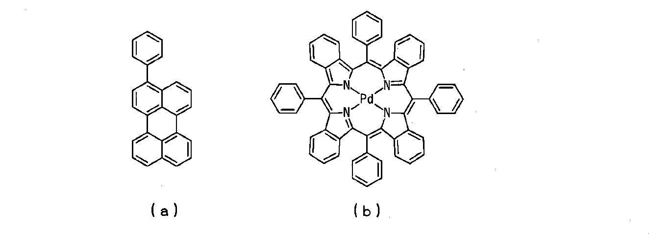
図8に、これら試作した太陽電池モジュールの構成を示す。図8に示す太陽電池モジュールは、単結晶シリコンを光電変換層とする太陽電池セルモジュール21の前面に封止剤層22を介してポリエチレンテレフタレートフィルム23を貼り合わせた構造を有するものである。封止剤層22の厚さ、ポリエチレンテレフタレートフィルム23の厚さは、何れも25μmである。太陽電池セルモジュール21の太陽電池セルのサイズは125mm×125mmであり、ポリエチレンテレフタレートフィルム23のサイズは150mm×150mmである。
作製した太陽電池2について、光電変換効率を計測した。結果を[表2]に示す。なお、[表2]において、「セル単体」は、封止剤層22やポリエチレンテレフタレートフィルム23を設置していない太陽電池セルモジュール21のみで測定した場合の計測結果であり、「参照例3」は、蛍光物質を含まないSEBSで封止剤層22を形成した場合の計測結果である。

[表2]に示す結果から明らかなように、光電変換層として多結晶シリコンを備えた太陽電池セルにおいても、実施例1の封止剤を用いた太陽電池において、最も良好な光電変換効率の値が得られた。このことは、上述したように、蛍光物質が、350nm以下の波長域に吸収のピークがあり、350nm~400nmの波長域の光を400nmを越える波長域の光よりも多く吸収することにより、光電変換層で利用できる光の総量を増加させることができ、また、平均粒径が8nmのCdSeナノ粒子からなることにより、光散乱を抑制し、入射する太陽光の大部分を有効利用することができたため、良好な光電変換効率の値が得られたと考えられる。
1 太陽電池、2,3 透明保護ガラス、4 太陽電池セル、5 接続配線、6 ターミナルボックス、7 封止剤層、8 シール材、9 フレーム、11,21 太陽電池セルモジュール、12,13 透明保護ガラス、14,22 封止剤層、23 ポリエチレンテレフタレートフィルム
Claims (10)
- 透明樹脂に蛍光物質が分散又は溶解されてなる太陽電池用封止剤であって、
前記蛍光物質は、350nm~400nmの波長域の光を400nmを越える波長域の光よりも多く吸収することを特徴とする太陽電池用封止剤。 - 前記蛍光物質は、400nm以下の波長域に吸収スペクトルのピークを有するとともに、500nm以上の波長域に発光スペクトルのピークを有することを特徴とする請求項1記載の太陽電池用封止剤。
- 前記蛍光物質の平均粒径が20nm以下であることを特徴とする請求項1又は請求項2記載の太陽電池用封止剤。
- 波長600nm~800nmにおける光透過率が90%以上であることを特徴とする請求項1乃至請求項3の何れか1項記載の太陽電池用封止剤。
- 前記透明樹脂は、スチレン・エチレン-ブチレン・スチレンを含有することを特徴とする請求項1乃至請求項4の何れか1項記載の太陽電池用封止剤。
- 光電変換層を有する太陽電池セル上に封止剤層を介して透明保護ガラスが貼り合わされてなる太陽電池であって、
前記封止剤層は、透明樹脂に蛍光物質が分散又は溶解されてなる太陽電池用封止剤により形成されており、
前記蛍光物質は、350nm~400nmの波長域の光を400nmを越える波長域の光よりも多く吸収することを特徴とする太陽電池。 - 前記蛍光物質は、400nm以下の波長域に吸収スペクトルのピークを有するとともに、500nm以上の波長域に発光スペクトルのピークを有することを特徴とする請求項6記載の太陽電池。
- 前記蛍光物質の平均粒径が20nm以下であることを特徴とする請求項6又は7記載の太陽電池。
- 前記封止剤層は、波長600nm~800nmにおける光透過率が90%以上であることを特徴とする請求項6乃至請求項8の何れか1項記載の太陽電池。
- 前記透明樹脂は、スチレン・エチレン-ブチレン・スチレンを含有することを特徴とする請求項6乃至請求項9の何れか1項記載の太陽電池。
Applications Claiming Priority (2)
| Application Number | Priority Date | Filing Date | Title |
|---|---|---|---|
| JP2010-033902 | 2010-02-18 | ||
| JP2010033902A JP2011171512A (ja) | 2010-02-18 | 2010-02-18 | 太陽電池用封止剤及びこれを用いた太陽電池 |
Publications (1)
| Publication Number | Publication Date |
|---|---|
| WO2011102466A1 true WO2011102466A1 (ja) | 2011-08-25 |
Family
ID=44483051
Family Applications (1)
| Application Number | Title | Priority Date | Filing Date |
|---|---|---|---|
| PCT/JP2011/053515 Ceased WO2011102466A1 (ja) | 2010-02-18 | 2011-02-18 | 太陽電池用封止剤及びこれを用いた太陽電池 |
Country Status (2)
| Country | Link |
|---|---|
| JP (1) | JP2011171512A (ja) |
| WO (1) | WO2011102466A1 (ja) |
Families Citing this family (3)
| Publication number | Priority date | Publication date | Assignee | Title |
|---|---|---|---|---|
| JP2013254854A (ja) * | 2012-06-07 | 2013-12-19 | Sharp Corp | 太陽電池モジュールおよび太陽光発電装置 |
| JP2015138829A (ja) * | 2014-01-21 | 2015-07-30 | 長州産業株式会社 | 太陽電池モジュール |
| WO2015129586A1 (ja) * | 2014-02-27 | 2015-09-03 | 京セラ株式会社 | 太陽電池モジュール |
Citations (9)
| Publication number | Priority date | Publication date | Assignee | Title |
|---|---|---|---|---|
| JPH07202243A (ja) * | 1993-12-28 | 1995-08-04 | Bridgestone Corp | 太陽電池モジュール |
| JP2006216560A (ja) * | 2005-02-03 | 2006-08-17 | Samsung Electronics Co Ltd | エネルギー変換膜および量子ドット薄膜 |
| WO2008047427A1 (fr) * | 2006-10-18 | 2008-04-24 | National Institute Of Advanced Industrial Science And Technology | Composition de résine fluorescente et module de batterie solaire utilisant ladite composition |
| WO2009151029A1 (ja) * | 2008-06-09 | 2009-12-17 | Jsr株式会社 | 封止材料およびそれを用いた太陽電池モジュール |
| JP2009302220A (ja) * | 2008-06-12 | 2009-12-24 | Techno Polymer Co Ltd | 太陽電池用封止膜および太陽電池モジュール |
| WO2010001703A1 (ja) * | 2008-06-30 | 2010-01-07 | 日立化成工業株式会社 | 波長変換フィルム、これを用いた太陽電池モジュール及びこれらの製造方法 |
| JP2010258020A (ja) * | 2009-04-21 | 2010-11-11 | Dainippon Printing Co Ltd | 太陽電池モジュールおよび太陽電池セル |
| JP2011009547A (ja) * | 2009-06-26 | 2011-01-13 | Nitto Denko Corp | 太陽電池モジュール用粘着シートおよび太陽電池モジュール |
| JP2011077088A (ja) * | 2009-09-29 | 2011-04-14 | Toppan Printing Co Ltd | 太陽電池モジュール用封止材シート及び太陽電池モジュール |
Family Cites Families (1)
| Publication number | Priority date | Publication date | Assignee | Title |
|---|---|---|---|---|
| US6744960B2 (en) * | 2000-03-06 | 2004-06-01 | Teledyne Lighting And Display Products, Inc. | Lighting apparatus having quantum dot layer |
-
2010
- 2010-02-18 JP JP2010033902A patent/JP2011171512A/ja active Pending
-
2011
- 2011-02-18 WO PCT/JP2011/053515 patent/WO2011102466A1/ja not_active Ceased
Patent Citations (9)
| Publication number | Priority date | Publication date | Assignee | Title |
|---|---|---|---|---|
| JPH07202243A (ja) * | 1993-12-28 | 1995-08-04 | Bridgestone Corp | 太陽電池モジュール |
| JP2006216560A (ja) * | 2005-02-03 | 2006-08-17 | Samsung Electronics Co Ltd | エネルギー変換膜および量子ドット薄膜 |
| WO2008047427A1 (fr) * | 2006-10-18 | 2008-04-24 | National Institute Of Advanced Industrial Science And Technology | Composition de résine fluorescente et module de batterie solaire utilisant ladite composition |
| WO2009151029A1 (ja) * | 2008-06-09 | 2009-12-17 | Jsr株式会社 | 封止材料およびそれを用いた太陽電池モジュール |
| JP2009302220A (ja) * | 2008-06-12 | 2009-12-24 | Techno Polymer Co Ltd | 太陽電池用封止膜および太陽電池モジュール |
| WO2010001703A1 (ja) * | 2008-06-30 | 2010-01-07 | 日立化成工業株式会社 | 波長変換フィルム、これを用いた太陽電池モジュール及びこれらの製造方法 |
| JP2010258020A (ja) * | 2009-04-21 | 2010-11-11 | Dainippon Printing Co Ltd | 太陽電池モジュールおよび太陽電池セル |
| JP2011009547A (ja) * | 2009-06-26 | 2011-01-13 | Nitto Denko Corp | 太陽電池モジュール用粘着シートおよび太陽電池モジュール |
| JP2011077088A (ja) * | 2009-09-29 | 2011-04-14 | Toppan Printing Co Ltd | 太陽電池モジュール用封止材シート及び太陽電池モジュール |
Also Published As
| Publication number | Publication date |
|---|---|
| JP2011171512A (ja) | 2011-09-01 |
Similar Documents
| Publication | Publication Date | Title |
|---|---|---|
| AU2008290641B2 (en) | Solar cell construction | |
| Liu et al. | Red-emissive carbon quantum dots enable high efficiency luminescent solar concentrators | |
| CN102077366B (zh) | 具有改善的光谱响应的光伏器件 | |
| CN106356410B (zh) | 高功率太阳能电池模块 | |
| US20100012177A1 (en) | PHOTON-CONVERSION MATERIALS (PCMs) IN POLYMER SOLAR CELLS-ENHANCEMENT EFFICIENCY AND PREVENTION OF DEGRADATION | |
| US20120132277A1 (en) | Photovoltaic device and method for making | |
| JP2011129925A (ja) | 半導体ナノ結晶を用いた太陽電池モジュール | |
| JP2010258020A (ja) | 太陽電池モジュールおよび太陽電池セル | |
| JP2007027271A (ja) | 太陽光発電モジュール | |
| WO2011102466A1 (ja) | 太陽電池用封止剤及びこれを用いた太陽電池 | |
| EP1724838A1 (en) | Tandem photovoltaic conversion device | |
| JP2003218367A (ja) | 太陽電池ユニット | |
| JP2013004806A (ja) | 太陽電池モジュール | |
| CN204243056U (zh) | 太阳能电池模块及太阳光发电系统 | |
| CN103579385A (zh) | 太阳能电池组合发电装置 | |
| CN110491963A (zh) | 一种双面光伏组件及光伏发电系统 | |
| CN102347712A (zh) | 双模块光能发电装置 | |
| CN205985030U (zh) | 一种光伏组件 | |
| CN214672614U (zh) | 基于硅量子点集中器的四端叠层钙钛矿太阳能电池 | |
| JP5422079B2 (ja) | 光起電力モジュール | |
| CN108183145A (zh) | 一种晶硅双玻光伏组件 | |
| CN104241426B (zh) | 防眩光耐候复合材料 | |
| JP2004140010A (ja) | タンデム形太陽電池 | |
| CN118540968A (zh) | 一种双面叠层电池、电池组件和光伏系统 | |
| JP2013098234A (ja) | 太陽電池 |
Legal Events
| Date | Code | Title | Description |
|---|---|---|---|
| 121 | Ep: the epo has been informed by wipo that ep was designated in this application |
Ref document number: 11744752 Country of ref document: EP Kind code of ref document: A1 |
|
| NENP | Non-entry into the national phase |
Ref country code: DE |
|
| 122 | Ep: pct application non-entry in european phase |
Ref document number: 11744752 Country of ref document: EP Kind code of ref document: A1 |