WO2011102423A1 - 光電変換素子、光電変換素子の製造方法、及び、高分子電解質型太陽電池 - Google Patents
光電変換素子、光電変換素子の製造方法、及び、高分子電解質型太陽電池 Download PDFInfo
- Publication number
- WO2011102423A1 WO2011102423A1 PCT/JP2011/053403 JP2011053403W WO2011102423A1 WO 2011102423 A1 WO2011102423 A1 WO 2011102423A1 JP 2011053403 W JP2011053403 W JP 2011053403W WO 2011102423 A1 WO2011102423 A1 WO 2011102423A1
- Authority
- WO
- WIPO (PCT)
- Prior art keywords
- photoelectric conversion
- conversion element
- polymer electrolyte
- metal layer
- metal
- Prior art date
- Legal status (The legal status is an assumption and is not a legal conclusion. Google has not performed a legal analysis and makes no representation as to the accuracy of the status listed.)
- Ceased
Links
Images




Classifications
-
- H—ELECTRICITY
- H01—ELECTRIC ELEMENTS
- H01G—CAPACITORS; CAPACITORS, RECTIFIERS, DETECTORS, SWITCHING DEVICES, LIGHT-SENSITIVE OR TEMPERATURE-SENSITIVE DEVICES OF THE ELECTROLYTIC TYPE
- H01G9/00—Electrolytic capacitors, rectifiers, detectors, switching devices, light-sensitive or temperature-sensitive devices; Processes of their manufacture
- H01G9/20—Light-sensitive devices
- H01G9/2059—Light-sensitive devices comprising an organic dye as the active light absorbing material, e.g. adsorbed on an electrode or dissolved in solution
-
- H—ELECTRICITY
- H01—ELECTRIC ELEMENTS
- H01M—PROCESSES OR MEANS, e.g. BATTERIES, FOR THE DIRECT CONVERSION OF CHEMICAL ENERGY INTO ELECTRICAL ENERGY
- H01M14/00—Electrochemical current or voltage generators not provided for in groups H01M6/00 - H01M12/00; Manufacture thereof
- H01M14/005—Photoelectrochemical storage cells
-
- H—ELECTRICITY
- H01—ELECTRIC ELEMENTS
- H01G—CAPACITORS; CAPACITORS, RECTIFIERS, DETECTORS, SWITCHING DEVICES, LIGHT-SENSITIVE OR TEMPERATURE-SENSITIVE DEVICES OF THE ELECTROLYTIC TYPE
- H01G9/00—Electrolytic capacitors, rectifiers, detectors, switching devices, light-sensitive or temperature-sensitive devices; Processes of their manufacture
- H01G9/20—Light-sensitive devices
- H01G9/2004—Light-sensitive devices characterised by the electrolyte, e.g. comprising an organic electrolyte
-
- Y—GENERAL TAGGING OF NEW TECHNOLOGICAL DEVELOPMENTS; GENERAL TAGGING OF CROSS-SECTIONAL TECHNOLOGIES SPANNING OVER SEVERAL SECTIONS OF THE IPC; TECHNICAL SUBJECTS COVERED BY FORMER USPC CROSS-REFERENCE ART COLLECTIONS [XRACs] AND DIGESTS
- Y02—TECHNOLOGIES OR APPLICATIONS FOR MITIGATION OR ADAPTATION AGAINST CLIMATE CHANGE
- Y02E—REDUCTION OF GREENHOUSE GAS [GHG] EMISSIONS, RELATED TO ENERGY GENERATION, TRANSMISSION OR DISTRIBUTION
- Y02E10/00—Energy generation through renewable energy sources
- Y02E10/50—Photovoltaic [PV] energy
- Y02E10/542—Dye sensitized solar cells
-
- Y—GENERAL TAGGING OF NEW TECHNOLOGICAL DEVELOPMENTS; GENERAL TAGGING OF CROSS-SECTIONAL TECHNOLOGIES SPANNING OVER SEVERAL SECTIONS OF THE IPC; TECHNICAL SUBJECTS COVERED BY FORMER USPC CROSS-REFERENCE ART COLLECTIONS [XRACs] AND DIGESTS
- Y02—TECHNOLOGIES OR APPLICATIONS FOR MITIGATION OR ADAPTATION AGAINST CLIMATE CHANGE
- Y02P—CLIMATE CHANGE MITIGATION TECHNOLOGIES IN THE PRODUCTION OR PROCESSING OF GOODS
- Y02P70/00—Climate change mitigation technologies in the production process for final industrial or consumer products
- Y02P70/50—Manufacturing or production processes characterised by the final manufactured product
Definitions
- the present invention relates to a photoelectric conversion element useful for solar cells and the like, and in particular, a photoelectric conversion element having a novel structure using a dye molecule, a method for producing the photoelectric conversion element, and further using the photoelectric conversion element.
- the present invention relates to a polymer electrolyte solar cell.
- photoelectric conversion elements using dyes that have been developed so far are those in which a functional group such as thiol is introduced into the dye and the dye is self-assembled into a planar electrode formed of a metal such as gold.
- the amount of the dye to be immobilized was limited.
- Patent Document 1 in order to solve such a problem, after depositing thin metal fine particles on a conductive substrate (electrode), a metal-sulfur compound is formed on the surface of the metal fine particles by a sulfur compound having dye molecules.
- a method is disclosed in which a dye is immobilized through bonding, an effective area as an electrode is increased, and dye sensitization efficiency is improved.
- this method is used, sufficient performance is not obtained as a photoelectric conversion element.
- Patent Document 2 discloses a substrate composed of a transparent conductive thin film, metal fine particles, a photoelectrode in which a photosensitizer is adsorbed on semiconductor fine particles such as titanium oxide, and a solar cell including this photoelectrode. ing. High energy conversion efficiency as a solar cell is expected by adsorbing a photosensitizer to metal fine particles, but titanium oxide and transparent conductive thin film used as semiconductor fine particles are high in cost and put to practical use. Has a problem.
- the object of the present invention is to use a metal that is inexpensive without using a transparent conductive substrate or titanium oxide, and increases the amount of adsorption / fixation of dye molecules to the metal layer to improve dye sensitization efficiency.
- SPR surface plasmon resonance
- the present inventors have intensively studied the configuration of the photoelectric conversion element. As a result, the present inventors have found that the above problem can be solved by using the following photoelectric conversion element, and have completed the present invention. .
- the photoelectric conversion element of the present invention is a photoelectric conversion element including a polymer electrolyte, a metal layer, and a dye molecule, wherein the metal layer is in contact with the polymer electrolyte, and the metal layer is It is formed on the surface and / or inside of a polyelectrolyte, and the dye molecules are adsorbed on the metal layer.
- the dye molecule is preferably a sulfur-containing compound.
- the polymer electrolyte is preferably an ion exchange resin.
- the photoelectric conversion element of the present invention preferably contains an electron acceptor and / or a redox couple.
- the photoelectric conversion element of the present invention preferably contains an electrolyte salt.
- the photoelectric conversion element of the present invention preferably contains an ether group-containing compound having a molecular weight of 50 to 400.
- the metal layer preferably forms a pair.
- the metal microstructure constituting the metal layer has a rich region toward the outside of the polymer electrolyte, and the polymer electrolyte toward the center of the polymer electrolyte. However, it is preferable to have a rich region.
- the polymer electrolyte solar cell of the present invention preferably includes the photoelectric conversion element.
- the method for producing a photoelectric conversion element of the present invention is a method for producing the photoelectric conversion element, wherein the metal is formed on the surface and / or inside of the polymer electrolyte by an electrolytic plating method or an electroless plating method.
- the electroless plating method includes an adsorption step in which a metal complex is adsorbed on the polymer electrolyte, a reduction step in which a reducing agent solution is brought into contact with the polymer electrolyte on which the metal complex has been adsorbed, and a metal layer is formed. It is preferable to contain.
- the photoelectric conversion element of the present invention can be produced at low cost without using an expensive material such as a transparent conductive substrate or titanium oxide, and is excellent in workability and useful.
- the photoelectric conversion element is for forming a metal layer having a nanostructure in order to increase the amount of adsorption / fixation of dye molecules to the metal layer and improve dye sensitization efficiency.
- the surface area (effective area) of the electrode increased, and in combination with this, the photoelectric conversion efficiency could be enhanced by the surface plasmon resonance (SPR) effect.
- the polymer electrolyte solar cell using the photoelectric conversion element emits light (light rays) not only in the visible region but also in the near infrared region, compared to conventional solar cells using a transparent conductive electrode.
- the photoelectric conversion element is useful not only for a solar cell excellent in photoelectric conversion efficiency but also for use as an optical sensor or the like.
- the method for producing a photoelectric conversion element of the present invention is carried out by the following steps (i) to (iv). Note that the following (i) pretreatment step is optional.
- the method for producing a photoelectric conversion element of the present invention includes: (i) a pretreatment step in which a polymer electrolyte is swollen with a solvent; and (ii) an electrolytic plating method or an electroless plating method. And / or the step of forming the metal layer therein, (iii) the step of adsorbing dye molecules to the metal layer, and (iv) the polymer electrolyte and the metal layer on which the dye molecules are adsorbed, And a step of swelling with a solvent or a solution.
- the electroless plating method includes an adsorption step in which a metal complex is adsorbed on the polymer electrolyte, and a reduction step in which a reducing agent solution is brought into contact with the polymer electrolyte on which the metal complex is adsorbed to form a metal layer. It is preferable.
- the manufacturing method of the photoelectric conversion element of this invention is demonstrated in detail.
- the polymer electrolyte for example, ion exchange
- a plating method electrolytic plating method or electroless plating method.
- Resin can be swollen.
- a swelling solvent swelling solvent
- the swelling of the polymer electrolyte in a swollen state is preferably 10% or more, more preferably 25% or more with respect to the thickness of the polymer electrolyte in a dried state.
- the metal complex By passing through the swelling process, the metal complex is easily adsorbed from the surface of the polymer electrolyte in the metal complex adsorption process in the plating method, and the reduction in the reducing agent solution is also performed in the reduction process. It is considered that the agent is easily adsorbed from the polymer electrolyte surface to the inside.
- the polymer electrolyte is not particularly limited, and a known one can be used. Since the polymer electrolyte does not use a transparent conductive electrode using ITO (indium tin oxide) or the like, the polymer electrolyte is excellent in flexibility and compared with conventional photoelectric conversion elements and solar cells using the same. Therefore, the expansion of application fields can be expected.
- the polymer electrolyte is not particularly limited as long as the metal complex can be sufficiently adsorbed.
- an ion exchange resin such as a fluorine ion exchange resin or a carbon ion exchange resin. It is more preferable to use, and it is particularly preferable to use a fluorine-based ion exchange resin.
- the fluorine-based ion exchange resin is not particularly limited, and a known resin can be used, and a resin introduced with a hydrophilic functional group such as a sulfonic acid group or a carboxyl group can be used.
- a resin introduced with a hydrophilic functional group such as a sulfonic acid group or a carboxyl group
- perfluorocarboxylic acid resin and perfluorosulfonic acid resin can be used.
- Nafion resin perfluorosulfonic acid resin, manufactured by DuPont
- Flemion (perfluorocarboxylic acid) Resin or perfluorosulfonic acid resin Alkali Glass Co., Ltd.
- the ion exchange resin contains an electrolyte salt as a photoelectric conversion element
- the degree of freedom in selecting the ion species of the electrolyte salt is large, and the range of combinations according to applications and characteristics can be widened. More preferably, it is a resin.
- the polymer electrolyte can be used in a shape suitable as a photoelectric conversion element obtained by the plating method, and may be a film shape, a plate (sheet) shape, a cylinder (cylindrical) shape, a columnar shape, a tubular shape, or the like. Can be used.
- the ion exchange resin is a perfluorocarboxylic acid resin or perfluorosulfonic acid resin that is a fluorine-based ion exchange resin
- the ion exchange capacity of the perfluorocarboxylic acid resin or perfluorosulfonic acid resin is as follows: 1.0 to 1.8 meq / g is preferable, and 1.2 to 1.6 meq / g is more preferable.
- the swelling solvent is a solvent that can swell the crosslinked polymer well, and varies depending on the type of polymer electrolyte.
- methanol, ethanol, propanol, hexafluoro-2-propanol, diethylene glycol, glycerin 2-methoxyethanol, acetone, dimethylformamide, N-methylformamide and the like are preferably used.
- the polymer electrolyte uses a fluorinated ion exchange resin such as a perfluorocarboxylic acid resin or a perfluorosulfonic acid resin, it contains methanol and / or ethanol, and further contains another solvent.
- the polymer electrolyte ion exchange resin
- these solvents are particularly preferable because they easily swell, are easy to handle, and have good workability.
- swelling the polymer electrolyte the degree of crystallinity of the polymer electrolyte is lowered, and in particular, the entanglement of the side chain having a functional group in the polymer electrolyte is alleviated, and the degree of freedom of segment motion about the side chain is reduced. Increase.
- conditions such as temperature and immersion time are not particularly limited, but the temperature is preferably 20 ° C. or higher for efficient swelling, more preferably 30 ° C. or higher. Preferably, it is 35 to 55 ° C.
- a method of immersing a polymer electrolyte for example, an ion exchange resin
- a solvent for swelling may be used, or a method of applying the solvent to the surface of the polymer electrolyte may be used.
- a method of immersing the polymer electrolyte because the operation is easy.
- the plating method in the present invention is not particularly limited, and an electroplating method, electroless plating, or the like can be used.
- the electroless plating method can also be applied to polymer electrolytes and the like, and even a complicated material shape (polymer electrolyte etc.) can obtain a metal layer (metal plating layer) with a uniform film thickness, preferable.
- the electroless plating method includes an adsorption step in which a metal complex is adsorbed on the polymer electrolyte, and a reduction step in which a reducing agent solution is brought into contact with the polymer electrolyte on which the metal complex is adsorbed to form a metal layer. Is preferred.
- the metal complex solution may be applied to the polymer electrolyte, but the polymer electrolyte is immersed in the metal complex solution. This is preferable because the operation is easy.
- the adsorption step is a step of adsorbing a metal complex to the polymer electrolyte
- conditions such as temperature and immersion time are not particularly limited.
- it is 30 ° C. or higher, and particularly preferably 35 to 55 ° C.
- the said adsorption process may contain the solvent used in the said pre-processing process in a metal complex solution, in order for a metal complex to adsorb
- the metal complex solution in the adsorption step is particularly limited as long as the metal layer (metal electrode) formed by reduction contains a metal complex that can function as an electrode.
- a chelated metal complex using a chelating agent such as phenanthroline metal complex and ethylenediaminetetraacetic acid (EDTA) can be used.
- concentration of the complex solution is not particularly limited, but is preferably, for example, 0.1 to 2.0% by weight, more preferably 0.2 to 1.5% by weight, and 0.3 to 1.1% by weight. % Is particularly preferred.
- the metal complex is a metal that can ensure conductivity and is not particularly limited as long as it is a metal complex that can be used as an electroless plating method, but contains a metal that can exhibit the SPR effect. Use of a complex is a more preferred embodiment.
- the reduction step in the present invention is a step of reducing the metal complex adsorbed in the polymer electrolyte by the adsorption step and precipitating the metal.
- a reducing agent solution having one concentration can be used, and a reducing agent solution having a plurality of concentrations can be used.
- a high-concentration reducing agent solution is brought into contact with the low-concentration reducing agent solution step by step. Is, for example, preferably 0.005 to 10% by weight, more preferably 0.008 to 8% by weight, and particularly preferably 0.01 to 6% by weight.
- the reducing agent solution having a concentration within the above range is divided into a plurality of times (multiple concentrations) from a low concentration to a high concentration in stages (gradually), to a polymer electrolyte adsorbed with a metal complex.
- a metal layer composed of fine metal particles (metal microstructure) having an extremely small average particle diameter can be formed, which is useful.
- a reducing agent solution in a low concentration into contact, a dense region with a high density of metal microstructure is formed in the vicinity of the polymer electrolyte interface, and the concentration of the reducing agent solution can be further increased.
- a dense metal layer (nanostructured metal electrode) is formed by contacting a high concentration reducing agent solution stepwise (gradually) from the low concentration reducing agent solution.
- a metal layer has a very large specific surface area and increases the effective area as an electrode, the amount of dye molecules adsorbed and immobilized on the metal layer can be increased to improve dye sensitization efficiency. In combination with this, the photoelectric conversion efficiency due to the SPR effect can be enhanced.
- the metal layer is formed on the polymer electrolyte in this way, the interface between the metal layer and the polymer electrolyte is not always clear, and the vicinity of the outer side of the polymer electrolyte.
- the metal component is rich, and a structure in which the polymer electrolyte component becomes rich step by step (gradually) can be taken as it goes to the center of the polymer electrolyte.
- the metal layer in the photoelectric conversion element of the present invention does not need to have a clear metal layer as a layer on the electrolyte, and at least the metals present near the outside of the polymer electrolyte are connected to each other, It is sufficient to form a portion with good electrical conductivity that can be used as Therefore, in the photoelectric conversion element of the present invention, the metal layer and the polymer electrolyte layer have a structure that does not have a clear visual interface, and a polymer electrolyte portion having a resistance value as the polymer electrolyte layer is provided.
- a structure (at least a pair of metal layers facing each other) sandwiched from both sides by a portion having good electrical conductivity that can contain metal as a main component and can be used as an electrode can be taken.
- the reason for having a polymer electrolyte portion (insulating portion) having a high resistance value as the metal layer decreases toward the center is that the plating process is carried out in water or a reducing agent solution (a polar medium in which the reducing agent is dissolved). Since the reducing agent molecule diffuses and penetrates from the outside of the polymer electrolyte to the central part, the reducing agent solution is difficult to penetrate to the central part. It is estimated that the metal itself constituting the layer cannot be completely connected.
- the obtained photoelectric conversion element (polymer electrolyte-metal layer composite) is cut in the vicinity of the central portion, and the polymer electrolyte (layer) is bonded in such a manner as to be sandwiched between the cut pieces.
- a photoelectric conversion element having an insulating portion may be used.
- the reducing agent solution is not particularly limited as long as the reducing agent is dissolved regardless of the shape of the polymer electrolyte.
- the reducing agent can be used by appropriately selecting the type according to the type of metal complex used in the metal complex solution adsorbed on the polymer electrolyte, such as sodium sulfite, hydrazine, sodium borohydride. Etc. can be used. In addition, when reducing a metal complex, you may add an acid or an alkali as needed.
- the concentration of the reducing agent solution is not particularly limited as long as it contains a sufficient amount of reducing agent to obtain the amount of metal to be deposited by reduction of the metal complex. It is also possible to use a concentration equivalent to that of the metal complex solution used in the case of forming a metal layer.
- the solvent containing alcohol can also be used in a reducing agent solution.
- the adsorption step and the reduction step may be performed once each, and this combination is preferably performed by performing the reduction step after the adsorption step. May be performed multiple times.
- the material of the metal layer that can be used in the photoelectric conversion element of the present invention is not particularly limited and can be manufactured using the above-described metal complex solution or the like, but in order to exert the surface plasmon resonance (SPR) effect, It is preferable to use gold, silver, copper or the like, and it is particularly preferable to use gold having high stability even in a solvent such as water.
- SPR effect can greatly improve the photoelectric conversion efficiency, and is useful as a polymer electrolyte solar cell or the like.
- washing process In the case where the adsorption step and the reduction step are repeatedly performed, in order to remove the reducing agent from the polymer electrolyte and easily perform the adsorption of the metal complex in the adsorption step, a washing step is performed after the reduction step, It is preferable to perform an adsorption process after the washing process.
- the washing step is not particularly limited, and the reducing agent may be removed by washing with water.
- the photoelectric conversion element in which a metal layer (metal electrode) is formed by a plating method has a cross section of the metal layer at a magnification of 800 times at the interface between the polymer electrolyte and the metal layer. Fractal, peninsular, island, icicle, polyp, and neck shape with narrow neck, tree shape, cocoon shape, cotton (observable by scanning electron microscope (SEM) photograph ( Figure 1) Even if it is in the form of at least one of cotton, fiber), strip, and irregular shape (the average particle diameter of the metal particles is more than about 1 ⁇ m, up to about 100 ⁇ m), and SEM photographs with a magnification of 5000 to 10000 times are fine.
- SEM scanning electron microscope
- the average particle size of metal fine structures (metal microstructures) of 1 ⁇ m or less is the low density of metal microstructures that cannot be observed, such as cocoon, cloud, cocoon, mist, and cotton (cotton).
- Rukoto can. Since the shape forms a complicated and dense structure (nanostructure), it becomes a metal layer (nanostructured metal electrode) having a very large specific surface area. In particular, unlike a metal layer formed by sputtering or the like on a transparent conductive substrate (ITO or the like), the specific surface area is greatly increased, so that a large amount of dye molecules can be adsorbed and immobilized on the metal layer.
- the surface resistance of the metal layer is preferably at the same level as the transparent conductive substrate (ITO or the like).
- the photoelectric conversion element of the present invention includes a polymer electrolyte, a metal layer, and a dye molecule, and the metal layer (nanostructured metal electrode) is in contact with the polymer electrolyte, And the said metal layer is formed in the surface and / or inside of the said polymer electrolyte,
- the said dye molecule is adsorb
- the dye molecule can be used without particular limitation as long as it is adsorbed on the metal layer.
- the adsorption examples include physical adsorption, electrostatic adsorption, and chemical adsorption, and it is preferable that the amount of adsorption / fixation of the dye molecules to the metal layer is large, that is, the dye molecules can be easily desorbed after adsorption.
- the dye molecule examples include black dye, ruthenium complex having bipyridine-carboxylic acid group, ruthenium complex having bipyridine group, ruthenium complex having phenanthroline group, ruthenium complex having quinoline group, ⁇ -diketonate complex, and osmium as the central metal.
- the metal constituting the metal layer uses gold or the like capable of exhibiting a surface plasmon resonance (SPR) effect
- a sulfur compound having a property of self-adsorption (self-organization) to the gold or the like is used.
- the sulfur compound is self-adsorbed (self-organized) on the surface of the metal layer, thereby forming a dense monomolecular film (monomolecular layer) on the surface of the metal layer, thereby irradiating the surface of the metal layer with light.
- the dye sensitization efficiency can be improved, and in addition to the SPR effect, a photoelectric conversion element having a higher photoelectric conversion efficiency can be obtained.
- Examples of the dye molecule that is the sulfur compound include a sulfur compound having a disulfide bond, a thiol group, or the like, and a compound in which the sulfur compound has incorporated the dye molecule.
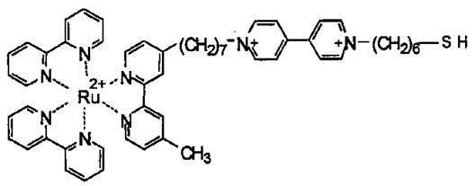
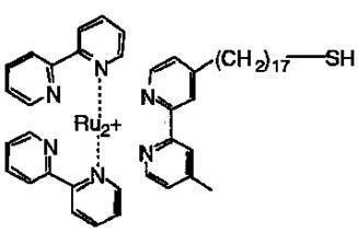
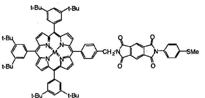
- Specific examples of the sulfur compound include the following chemical formulas 2 to 8.
- the dye molecules can be sufficiently adsorbed and immobilized on the surface of the metal layer.
- the photoelectric conversion element of the present invention is preferably in a state where the polymer electrolyte (layer) and the metal layer adsorbed with the dye molecules are swollen and filled with the electrolytic solution. By setting it in a swollen (and filled) state, light is transmitted (arrives) not only to the metal layer on the surface of the polymer electrolyte but also to the internal metal layer, and the dye sensitizing effect and the SPR effect are efficiently improved. Can be useful.
- the dye molecule-containing solution used in the dye molecule adsorption step may serve as a swelling step together with the adsorption of the dye molecules to the metal layer.
- the solvent used in the electrolytic solution (or dye molecule-containing solution) is preferably a solvent that can dissolve the dye molecules and that can also swell the metal layer.
- the electrolyte solution may be a non-aqueous (organic) electrolyte solution or an aqueous electrolyte solution.
- the polymer electrolyte may contain some solvent molecules of the electrolytic solution.
- a noble metal in order to prevent deterioration due to ionization or corrosion of the metal of the metal layer in the charge / discharge process of the photoelectric conversion element, as the metal constituting the metal layer, It is preferable to use a noble metal, and in particular, gold, silver and copper are preferably used, and more preferably gold in order to exhibit a surface plasmon resonance (SPR) effect.
- SPR surface plasmon resonance
- a non-aqueous polar liquid can also be used as a solvent.
- a non-aqueous polar liquid having a high dielectric constant and decomposition voltage is used as a solvent, the potential window is widened, electrolysis is unlikely to occur, and it is electrochemically stable, resulting in high withstand voltage and energy density. Becomes larger.
- a metal other than a noble metal such as gold (for example, copper) that is difficult to use as an electrode of a photoelectric conversion element when water is used as a solvent may be used as an electrode. This is also advantageous in terms of cost.
- the solvent contained in the non-aqueous electrolyte include propylene carbonate, N-methylpyrrolidone, dimethyl sulfoxide, acetonitrile, N, N-dimethylformamide, N-methylformamide (NMF), tetrahydrofuran (THF), Hexamethylphosphoric triamide, ⁇ -butyrolactone, 1,2-dimethoxyethane, N-methylacetamide, sulfolane ethylene carbonate, glutaronitrile, adiponitrile, nitromethane, nitroethane, pyridine, preferably propylene carbonate, n-methylpyrrolidone, dimethyl
- polar liquid water a particularly preferred polar liquid, N- methylform
- NMF N-methylformamide
- THF tetrahydrofuran
- volume ratio is preferably 10:90 to 35:65, more preferably 15:85 to 30:70, and particularly preferably 20:80 to 25:75. If the amount of NMF is less than the above ratio, it cannot swell sufficiently. On the other hand, if the proportion of NHF is more than the above ratio, it swells too much and is formed on the surface and / or inside of the polymer electrolyte. The metal layer is detached and the metal layer cannot be obtained, which is not preferable.
- the electrolytic solution not only the electrolytic solution but also an ether group-containing compound having a molecular weight of 50 to 400 can be contained, and the molecular weight is more preferably 100 to 300.
- the molecular weight is more preferably 100 to 300.
- the present invention it is possible to obtain a photoelectric conversion element having higher photoelectric conversion efficiency by blending and dissolving the electron acceptor, redox couple, and electrolyte salt described below in the ether group-containing compound. It is possible and effective. Further, when the ether group-containing compound is non-volatile, it is excellent in workability and durability, for example, it is not necessary to replenish the electrolyte solution for a long time. Furthermore, PEG and the like are useful because they can swell a polymer electrolyte (polyelectrolyte-metal layer composite) in which a metal layer is formed.
- ether group containing compounds such as said PEG
- the measuring method of molecular weight is based on gel permeability evaluation.
- the degree of swelling when swelling with the electrolytic solution is preferably 5 to 50%, more preferably 10 to 35%.
- the metal layer (metal electrode) structure is easy to maintain the state at the time of forming the metal layer, and stable photoelectric conversion is possible, which is preferable.
- the electrolytic solution preferably contains an electron acceptor and / or a redox couple.
- the electron acceptor known ones can be used without particular limitation, but viologens that can be used in the field of solar cells and the like, quinones having a base oxidation-reduction potential, alloxazines, or combinations thereof are used. In particular, it is preferable to use viologens. Use of the electron acceptor enables efficient charge separation and is useful.
- ferrocene derivatives that can be used in the field of solar cells and the like can be used, and ferrocenyl alcohol is particularly preferably used.
- ferrocene derivatives that can be used in the field of solar cells and the like can be used, and ferrocenyl alcohol is particularly preferably used.
- the electrolytic solution preferably contains an electrolyte salt.
- the electrolyte salt is not particularly limited.
- at least one alkali metal halide selected from the group consisting of sodium, lithium, cesium, and rubidium (fluoride, chloride, bromide, etc.)
- sodium hydroxide preferably sodium perchlorate, cesium chloride, cesium hydroxide, lithium chloride, lithium fluoride, and the like, and particularly preferably cesium chloride, lithium chloride, and the like.
- the electron acceptor, redox couple and electrolyte salt contained in the electrolytic solution may be used alone or mixed, but the content in the electrolytic solution is preferably 0.
- the amount is 1 to 10.0 mol / l, and more preferably 0.2 to 5.0 mol / l. Within the above range, the electrical conductivity is improved, which is useful in terms of photoelectric conversion.
- the photoelectric conversion element of the present invention can be used as a dye-sensitized solar cell without changing the configuration of the photoelectric conversion element when the metal layers are formed in pairs.
- a solar cell without a shield can be formed, which is useful in terms of cost and workability.
- Example 1 (Pretreatment process and plating process) About the membrane-shaped polymer electrolyte (fluorine resin-based ion exchange resin: perfluorocarboxylic acid resin, trade name “Flemion”, manufactured by Asahi Glass Co., Ltd., ion exchange capacity: 1.44 meq / g) having a film thickness of 110 ⁇ m when dried The following steps (1) to (4) were performed.
- fluorine resin-based ion exchange resin perfluorocarboxylic acid resin, trade name “Flemion”, manufactured by Asahi Glass Co., Ltd., ion exchange capacity: 1.44 meq / g
- Pretreatment step a membrane polymer electrolyte having a film thickness of 110 ⁇ m when dried (fluorine resin ion exchange resin: perfluorocarboxylic acid resin, trade name “Flemion”, manufactured by Asahi Glass Co., Ltd., ion exchange capacity 1.44 meq / g) was immersed in ethanol as a swelling solvent at 20 ° C. for 30 minutes or more.
- the film thickness of the membrane-like polymer electrolyte swollen is measured, and the ratio of the film thickness after swelling to the dry film thickness (degree of swelling (%)) is calculated, so that the degree of swelling is 50%.
- the membrane polymer electrolyte was immersed in a swelling solvent.
- the adsorbed dichlorophenanthroline gold complex was reduced to form nanostructured gold electrodes on and inside the membrane polymer electrolyte.
- the temperature of the aqueous solution was set to 60 to 80 ° C., and the dichlorophenanthroline gold complex was reduced for 6 hours while adding sodium sulfite stepwise.
- Washing step The membrane polymer electrolyte having a gold electrode formed on the surface was taken out and washed with water at 70 ° C. for 1 hour to obtain a polymer electrolyte-metal layer composite.
- the ionic species contained in the polymer electrolyte is sodium ions derived from sodium sulfite.
- the surface resistance on which the obtained metal layer (gold electrode) was formed was a polymer electrolyte-metal layer composite of several ⁇ / cm.
- the swollen complex is a metal that does not elute dye molecules and is strongly adsorbed (fixed) to the surface of the metal layer (gold electrode) of the nanostructure (metal microstructure) in which the dye molecules form gold fine particles, fractal structures, etc. It was possible to obtain a polymer electrolyte-metal layer-dye molecule complex, that is, a photoelectric conversion element A in which the layers formed a pair.
- the photoelectric conversion element A is shown in FIG. 1 (SEM photograph: magnification 800 times).
- the photoelectric conversion element A is cut in a direction perpendicular to the thickness direction, a cross section is cut out, and the cut cross section is subjected to a predetermined process for SEM observation, and then the cross section is cut.
- a predetermined process for SEM observation was observed by SEM photographs.
- the photoelectric conversion element A (a metal layer forms a pair) was cut at the center to obtain a photoelectric conversion element B having a metal layer only on one side.
- the electrode (working electrode) surface of the photoelectric conversion element B having a metal layer only on one surface is brought into contact (immersion / swelling) with the electrolyte solution having the composition shown in Table 1, and the portion not in contact with the electrolyte solution on the electrode (edge) Part) and the counter electrode (Pt plate) inserted in the electrolyte solution with a conducting wire, and using the Ag / AgCl (saturated KCl) electrode as a reference electrode, the ITO (electrochemical cell) shown in FIG.
- the metal layer side was sealed with.
- the photocurrent action spectrum means not only a mere photocurrent but also a photocurrent based on a dye sensitizing effect or an SPR effect.
- light irradiation is performed at a constant distance from a light source to a sample (electrochemical cell or the like).
- ⁇ Comparative Example 1> Instead of using the photoelectric conversion element B of the present invention in the same apparatus configuration as in Example 1, a gold electrode (gold plated) formed by depositing gold with a thickness of 0.2 ⁇ m on the ITO electrode by sputtering. In the layer), the dye molecules used in Example 1 were dissolved and adsorbed in methylene chloride, and this was used as the photoelectric conversion element C. White light was irradiated from the electrolytic solution side of the photoelectric conversion element C (manufactured by JASCO Corporation, Xe Hypermonolite HM-250Q type, 380 to 1200 nm), and a photocurrent action spectrum and absorbance were measured. . The spectrum and absorbance measurement results (graph) are shown in FIG.
- white light refers to a wavelength range of 380 to 1200 nm, and includes an ultraviolet light, visible light, and near infrared light region.
- Example 2 The photoelectric conversion element A of Example 1 was immersed in an electrolytic solution having the composition shown in Table 1 for 1 hour at 50 ° C., and then pulled up, so that ITO could be used as a transparent electrode quickly so that moisture would not dry. In this way, two pieces of ITO with a thickness of about 2 mm are constructed so that the photoelectric conversion element A is in close contact with each other, and one side of ITO (transparent electrode) is used as a working electrode, and the other side of ITO as a counter electrode is used as a counter electrode.
- ITO transparent electrode
- the absolute value of the photocurrent (photocurrent action spectrum) value is reduced to about a quarter of that of FIG. 3, but the spectrum shape is very similar. It is presumed that photocurrent separation occurred inside the resin (polymer electrolyte) far from the surface in contact with ITO, with a photocurrent flowing between the layers (metal electrodes).
- the photoelectric conversion element (cell) is irradiated with light from the upper surface of the ITO on the working electrode side by applying to a solar cell characteristic evaluation apparatus using an artificial light source (manufactured by Spectrometer Co., Ltd., pseudo solar light source OTENTO-SUNII spectrometer, Xe light). Then, the IV characteristic at that time was measured, and the result (graph) was obtained as shown in FIG. From FIG. 6, an electromotive force of about 80 mV between both electrodes of the photoelectric conversion element (cell) is present between the two electrodes of the photoelectric conversion element, even though there is no conjugated redox pair used in the conventional solar cell. Photovoltaic power) was generated, and it became clear that it functions as a solar cell.
- an artificial light source manufactured by Spectrometer Co., Ltd., pseudo solar light source OTENTO-SUNII spectrometer, Xe light
- Example 3 Evaluation was made with the same composition except that the water in the electrolyte solution was replaced with PEG (molecular weight 200) in Example 2.
- white light Japan
- ITO electrode used in Example 2 a voltage was applied between the opposing electrodes of the composite film with a conductive metal in contact with the end.
- Xe hyper monolite HM-250Q type (380-1200 nm) manufactured by Spectroscopic Co., Ltd. was irradiated to evaluate photocurrent (photocurrent action spectrum). From the evaluation result, a photocurrent (316 nA / cm 2 ) was obtained.
- the photocurrent (95 nA / cm 2 ) based on light in the near infrared region (680 to 1200 nm, using a filter to irradiate only near infrared light.) It is clear that photocurrent reaching up to one third is observed, and by using a photoelectric conversion element having a metal layer (gold electrode) with a nanostructure (metal microstructure), the SPR effect is achieved together with the dye sensitization effect. Based on this, it is estimated that it was influenced (effect).
- Example 4 The same experiment as in Example 3 was performed by changing the composition of the electrolyte solution of Example 3 as shown in Table 1. From this result, the photocurrent value based on irradiation with white light is 3 to 34 times, the photocurrent value based on the near infrared region is 5 to 6 times, and in the photoelectric conversion element (cell) not using ITO, the photocurrent is It was found to be greatly affected by the electrolyte components (especially electrolyte salts). In the composition of the electrolytic solution in Example 4, the absorbance before and after the dye molecule adsorption was measured. The absorbance before dye adsorption is shown in FIG.
- Dye molecule concentration 0.5 mM in the adsorbent Sodium perchlorate concentration: 0.1M Cesium chloride concentration: 1.0M MV 2+ (manufactured by Tokyo Chemical Industry Co., Ltd., 1,1′-dimethyl-4,4′-pyridinium dichloride hydrate, common name: methyl viologen) Concentration: 0.5 mM
- the electrolyte salt contained in the electrolytic solution filling the inside of the photoelectric conversion element was changed from the commonly used sodium perchlorate to cesium chloride, the concentration was changed, and the photocurrent was measured. A large photocurrent of about 10 times could be obtained, and it was confirmed that it was very useful as a polymer electrolyte solar cell.
Landscapes
- Engineering & Computer Science (AREA)
- Chemical & Material Sciences (AREA)
- Power Engineering (AREA)
- Materials Engineering (AREA)
- Microelectronics & Electronic Packaging (AREA)
- Chemical Kinetics & Catalysis (AREA)
- Electrochemistry (AREA)
- General Chemical & Material Sciences (AREA)
- Photovoltaic Devices (AREA)
- Hybrid Cells (AREA)
Abstract
透明導電性基板や酸化チタン等を使用せず安価であり、色素分子の金属層への吸着・固定量を増大させて、色素増感効率を向上させるため、金属層をナノ構造に形成して、電極として表面積(実効面積)を増大させ、更に、表面プラズモン共鳴(SPR)効果による光電変換効率が増強した光電変換素子、及び、前記光電変換素子の製造方法、更には、前記光電変換素子を用いた高分子電解質型太陽電池を提供する。高分子電解質、金属層、及び、色素分子を含む光電変換素子であって、前記金属層が、前記高分子電解質と接し、かつ、前記金属層が、前記高分子電解質の表面及び/又は内部に形成されたものであり、前記色素分子が、前記金属層に吸着していることを特徴とする光電変換素子。
Description
本発明は、太陽電池等に有用な光電変換素子に関し、特に、色素分子を利用する新規な構造の光電変換素子、及び、前記光電変換素子の製造方法、更には、前記光電変換素子を用いた高分子電解質型太陽電池に関する。
近年、石油や石炭など化石燃料の使用は、地球温暖化の原因として懸念され、代替エネルギーの重要性が増してきており、太陽光から電気を生み出す太陽電池が、重要な代替エネルギー供給源の一つとして、注目を集めている。
このような中で、太陽電池などに用いられる光電変換素子が、近年、色素増感方法により、盛んに研究・開発されている。これは、透明導電性基板(電極)上に薄膜化した多孔質の化合物半導体(例えば、多孔質酸化チタン)の表面に錯体色素や有機色素を固着させた基本構造をもつもので、色素が光を吸収し、半導体の伝導帯に電子を移すことによって駆動するものであり、特に可視光領域を利用することを目的としている。このような色素を用いる光電変換素子を高性能化するには、色素を確実に固定し、固定する色素の絶対量を増やすことなどが挙げられる。
しかし、これまでに開発された色素を用いる光電変換素子は、色素にチオールのような官能基を導入し、前記色素を金のような金属から形成される平面型電極に、自己組織化することにより、固定化させたものであり、固定化される色素の量に限界があった。
特許文献1では、このような問題を解決するため、導電性基板(電極)上に薄膜状の金属微粒子を堆積した後、この金属微粒子の表面に、色素分子を有するイオウ化合物により、金属-イオウ結合を介して、色素を固定化し、電極として実効面積を増大させ、色素増感効率の向上を図る方法が開示されている。しかし、この方法を用いた場合であっても、光電変換素子として、十分な性能が得られていない。
また、特許文献2には、透明導電性薄膜からなる基板と金属微粒子と、酸化チタン等の半導体微粒子に光増感剤が吸着している光電極や、この光電極を備える太陽電池が開示されている。金属微粒子に光増感剤が吸着することにより、太陽電池としての高いエネルギー変換効率が期待されるが、半導体微粒子として使用される酸化チタンや、透明導電性薄膜は、コストが高く、実用化には問題を有している。
そこで、本発明の目的は、透明導電性基板や酸化チタン等を使用せず安価であり、色素分子の金属層への吸着・固定量を増大させて、色素増感効率を向上させるため、金属層をナノ構造に形成して、電極として表面積(実効面積)を増大させ、更に、表面プラズモン共鳴(SPR)効果による光電変換効率が増強した光電変換素子、及び、前記光電変換素子の製造方法、更には、前記光電変換素子を用いた高分子電解質型太陽電池を提供することにある。
本発明者らは、上記の目的を達成するため、光電変換素子の構成について鋭意検討した結果、下記の光電変換素子を用いることにより上記課題を解決できることを見出し、本発明を完成するに至った。
すなわち、本発明の光電変換素子は、高分子電解質、金属層、及び、色素分子を含む光電変換素子であって、前記金属層が、前記高分子電解質と接し、かつ、前記金属層が、前記高分子電解質の表面及び/又は内部に形成されたものであり、前記色素分子が、前記金属層に吸着していることを特徴とする。
本発明の光電変換素子は、前記色素分子が、イオウ含有化合物であることが好ましい。
本発明の光電変換素子は、前記高分子電解質が、イオン交換樹脂であることが好ましい。
本発明の光電変換素子は、電子受容体及び/又は酸化還元対を含有することが好ましい。
本発明の光電変換素子は、電解質塩を含有することが好ましい。
本発明の光電変換素子は、分子量50~400のエーテル基含有化合物を含有することが好ましい。
本発明の光電変換素子は、前記金属層が、対を形成することが好ましい。
本発明の光電変換素子は、前記高分子電解質の外側に向かって、前記金属層を構成する金属微細構造が、リッチな領域を有し、前記高分子電解質の中心に向かって、前記高分子電解質が、リッチな領域を有することが好ましい。
本発明の高分子電解質型太陽電池は、前記光電変換素子を備えることが好ましい。
また、本発明の光電変換素子の製造方法は、前記光電変換素子の製造方法であって、電解メッキ方法、又は、無電解メッキ方法により、前記高分子電解質の表面及び/又は内部に、前記金属層を形成する工程と、前記金属層に、色素分子を吸着させる工程と、前記高分子電解質、及び、前記色素分子の吸着した金属層を、溶媒又は溶液により、膨潤させる工程と、を含むことが好ましく、前記無電解メッキ方法が、前記高分子電解質に金属錯体を吸着させる吸着工程と、前記金属錯体が吸着した高分子電解質に還元剤溶液を接触させ、金属層を形成する還元工程と、を含むことが好ましい。
本発明の光電変換素子は、透明導電性基板や酸化チタン等の高価な材料を使用することなく、安価に製造でき、更に作業性にも優れ、有用である。また、前記光電変換素子は、色素分子の金属層への吸着・固定量を増大させて、色素増感効率を向上させるため、ナノ構造を有する金属層を形成するものであり、前記ナノ構造を有することにより、電極として表面積(実効面積)が増大し、これと相まって、表面プラズモン共鳴(SPR)効果により、光電変換効率を増強させることを可能にした。また、前記光電変換素子を用いた高分子電解質型太陽電池は、これまでの透明導電性電極を用いた太陽電池に比べて、可視領域だけではなく、近赤外領域付近の光(光線)をも有効に利用することができ、これは、金属層のナノ構造と、これに伴うSPR効果によるものと推定される。また、前記光電変換素子は、光電変換効率に優れた太陽電池だけでなく、光センサーなどとしての用途にも、有用である。
<光電変換素子の製造方法>
本発明の光電変換素子の製造方法は、以下の(i)~(iv)の工程により、実施される。なお、下記の(i)前処理工程については、任意である。
本発明の光電変換素子の製造方法は、以下の(i)~(iv)の工程により、実施される。なお、下記の(i)前処理工程については、任意である。
本発明の光電変換素子の製造方法は、(i)高分子電解質を、溶媒により膨潤させる前処理工程と、(ii)電解メッキ方法、又は、無電解メッキ方法により、前記高分子電解質の表面及び/又は内部に、前記金属層を形成する工程と、(iii)前記金属層に、色素分子を吸着させる工程と、(iv)前記高分子電解質、及び、前記色素分子の吸着した金属層を、溶媒又は溶液により、膨潤させる工程と、を含むことが好ましい。特に、無電解メッキ方法は、前記高分子電解質に金属錯体を吸着させる吸着工程と、前記金属錯体が吸着した高分子電解質に還元剤溶液を接触させ、金属層を形成する還元工程と、を含むことが好ましい。以下に、本発明の光電変換素子の製造方法について、詳細に説明する。
(i)前処理工程
本発明の光電変換素子の製造方法において、メッキ方法(電解メッキ方法、又は、無電解メッキ方法)の事前に行われる前処理工程として、前記高分子電解質(例えば、イオン交換樹脂)を膨潤させる膨潤工程を行うことができる。前記膨潤工程は、前記高分子電解質に、膨潤用の溶媒(膨潤溶媒)を浸透させるものである。なお、前記高分子電解質の膨潤した状態での厚さを前記高分子電解質の乾燥した状態での厚さに対して10%以上とする膨潤が好ましく、より好ましくは、25%以上である。前記膨潤工程を経ることにより、前記メッキ方法における金属錯体の吸着工程において、金属錯体が前記高分子電解質の表面から、内部へ吸着しやすくなり、また、還元工程においても、還元剤溶液中の還元剤が、高分子電解質表面から、内部へと吸着しやすくなると考えられる。
本発明の光電変換素子の製造方法において、メッキ方法(電解メッキ方法、又は、無電解メッキ方法)の事前に行われる前処理工程として、前記高分子電解質(例えば、イオン交換樹脂)を膨潤させる膨潤工程を行うことができる。前記膨潤工程は、前記高分子電解質に、膨潤用の溶媒(膨潤溶媒)を浸透させるものである。なお、前記高分子電解質の膨潤した状態での厚さを前記高分子電解質の乾燥した状態での厚さに対して10%以上とする膨潤が好ましく、より好ましくは、25%以上である。前記膨潤工程を経ることにより、前記メッキ方法における金属錯体の吸着工程において、金属錯体が前記高分子電解質の表面から、内部へ吸着しやすくなり、また、還元工程においても、還元剤溶液中の還元剤が、高分子電解質表面から、内部へと吸着しやすくなると考えられる。
(高分子電解質)
前記高分子電解質としては、特に制限されるものではなく、公知のものを使用できる。前記高分子電解質は、ITO(インジウム錫酸化物)などを用いた透明導電性電極を使用するものではないため、フレキシブル性に優れ、これまでの光電変換素子やこれを用いた太陽電池等に比べて、応用分野の拡大が期待できる。なお、高分子電解質には、金属錯体を十分に吸着させることができれば、特に制限されないが、たとえば、イオン交換樹脂を用いることが好ましくは、フッ素系イオン交換樹脂や、炭素系イオン交換樹脂などを用いることがより好ましく、特に好ましくは、フッ素系イオン交換樹脂を用いることである。前記フッ素系イオン交換樹脂は、特に限定されるものではなく、公知の樹脂を用いることができ、スルホン酸基や、カルボキシル基などの親水性官能基を導入したものを用いることができる。前記フッ素系イオン交換樹脂の具体例としては、パーフルオロカルボン酸樹脂、パーフルオロスルホン酸樹脂を用いることができ、例えばNafion樹脂(パーフルオロスルホン酸樹脂、DuPont社製)、フレミオン(パーフルオロカルボン酸樹脂またはパーフルオロスルホン酸樹脂、旭硝子社製)を用いることができる。前記イオン交換樹脂は、光電変換素子として電解質塩を含有する場合に、電解質塩のイオン種を選択する自由度が大きく、用途や特性に応じた組み合わせの幅を広げることができることから、陽イオン交換樹脂であることが、より好ましい。なお、前記高分子電解質は、前記メッキ方法により得られる光電変換素子として適した形状のものを用いることができ、膜状、板(シート)状、筒(円筒)状、柱状や管状等の所望の形状を用いることができる。
前記高分子電解質としては、特に制限されるものではなく、公知のものを使用できる。前記高分子電解質は、ITO(インジウム錫酸化物)などを用いた透明導電性電極を使用するものではないため、フレキシブル性に優れ、これまでの光電変換素子やこれを用いた太陽電池等に比べて、応用分野の拡大が期待できる。なお、高分子電解質には、金属錯体を十分に吸着させることができれば、特に制限されないが、たとえば、イオン交換樹脂を用いることが好ましくは、フッ素系イオン交換樹脂や、炭素系イオン交換樹脂などを用いることがより好ましく、特に好ましくは、フッ素系イオン交換樹脂を用いることである。前記フッ素系イオン交換樹脂は、特に限定されるものではなく、公知の樹脂を用いることができ、スルホン酸基や、カルボキシル基などの親水性官能基を導入したものを用いることができる。前記フッ素系イオン交換樹脂の具体例としては、パーフルオロカルボン酸樹脂、パーフルオロスルホン酸樹脂を用いることができ、例えばNafion樹脂(パーフルオロスルホン酸樹脂、DuPont社製)、フレミオン(パーフルオロカルボン酸樹脂またはパーフルオロスルホン酸樹脂、旭硝子社製)を用いることができる。前記イオン交換樹脂は、光電変換素子として電解質塩を含有する場合に、電解質塩のイオン種を選択する自由度が大きく、用途や特性に応じた組み合わせの幅を広げることができることから、陽イオン交換樹脂であることが、より好ましい。なお、前記高分子電解質は、前記メッキ方法により得られる光電変換素子として適した形状のものを用いることができ、膜状、板(シート)状、筒(円筒)状、柱状や管状等の所望の形状を用いることができる。
たとえば、前記イオン交換樹脂がフッ素系のイオン交換樹脂であるパーフルオロカルボン酸樹脂またはパーフルオロスルホン酸樹脂である場合には、これらパーフルオロカルボン酸樹脂またはパーフルオロスルホン酸樹脂のイオン交換容量としては、1.0~1.8meq/gのものを用いることが好ましく、より好ましくは、1.2~1.6meq/gである。前記範囲内にあるフッ素系イオン交換樹脂を用いることにより、造膜特性、及び、メッキ特性(適性)に優れ、有用である。
前記膨潤用の溶媒としては、架橋した高分子を良く膨潤させることができる溶媒であり、高分子電解質の種類により異なるが、例えば、メタノール、エタノール、プロパノール、ヘキサフルオロ-2-プロパノール、ジエチレングリコール、グリセリン、2-メトキシエタノール、アセトン、ジメチルホルムアミド、N-メチルホルムアミド等を用いることが好適である。特に、前記膨潤工程において、前記高分子電解質が、パーフルオロカルボン酸樹脂またはパーフルオロスルホン酸樹脂などのフッ素系イオン交換樹脂を用いる場合に、メタノール及び/又はエタノールを含み、更に他の溶媒を含む混合溶媒を浸透させて、前記高分子電解質(イオン交換樹脂)を膨潤させることが好ましい。これらの溶媒は、膨潤がしやすく、取り扱いが容易であり、作業性が良好であるため、特に好ましい。また、高分子電解質を膨潤させることにより、高分子電解質の結晶化度が低下し、特に高分子電解質中の官能基を有する側鎖の絡み合いが緩和され、側鎖についてのセグメント運動の自由度が増大する。
前記前処理工程は、温度及び浸漬時間等の条件が特に限定されるものではないが、温度20℃以上であることが効率よく膨潤するために好ましく、より好ましくは、30℃以上であり、特に好ましくは、35~55℃である。
前記前処理工程において、膨潤用の溶媒中に、高分子電解質(例えば、イオン交換樹脂)を浸漬させる方法を用いてもよく、また前記溶媒を高分子電解質の表面に塗布する方法を用いても良いが、高分子電解質を浸漬させる方法を用いることが、作業が容易であるため、好ましい。
(ii)メッキ方法
本発明におけるメッキ方法としては、特に限定されず、電気メッキ方法や、無電解メッキ等を用いることができる。特に無電解メッキ方法は、高分子電解質等にも適用でき、素材形状の複雑なもの(高分子電解質等)に対しても、均一な膜厚の金属層(金属メッキ層)が得られるため、好ましい。前記無電解メッキ方法は、前記高分子電解質に金属錯体を吸着させる吸着工程と、前記金属錯体が吸着した高分子電解質に還元剤溶液を接触させ、金属層を形成する還元工程と、を含むことが好ましい。
本発明におけるメッキ方法としては、特に限定されず、電気メッキ方法や、無電解メッキ等を用いることができる。特に無電解メッキ方法は、高分子電解質等にも適用でき、素材形状の複雑なもの(高分子電解質等)に対しても、均一な膜厚の金属層(金属メッキ層)が得られるため、好ましい。前記無電解メッキ方法は、前記高分子電解質に金属錯体を吸着させる吸着工程と、前記金属錯体が吸着した高分子電解質に還元剤溶液を接触させ、金属層を形成する還元工程と、を含むことが好ましい。
(吸着工程)
本発明の光電変換素子の製造方法において、無電解メッキ方法を採用する場合、吸着工程としては、金属錯体溶液を高分子電解質に塗布してもよいが、高分子電解質を金属錯体溶液に浸漬させることにより行えば、作業が容易であるため、好ましい。
本発明の光電変換素子の製造方法において、無電解メッキ方法を採用する場合、吸着工程としては、金属錯体溶液を高分子電解質に塗布してもよいが、高分子電解質を金属錯体溶液に浸漬させることにより行えば、作業が容易であるため、好ましい。
前記吸着工程は、高分子電解質に金属錯体を吸着させる工程であれば、温度及び浸漬時間等の条件が特に限定されるものではないが、温度20℃以上であることが効率よく膨潤するために好ましく、より好ましくは、30℃以上であり、特に好ましくは、35~55℃である。また、前記吸着工程は、金属錯体が高分子電解質中へ容易に吸着させるために、金属錯体溶液中に、前記前処理工程において用いられる溶媒を含んでいても良い。ここで、前記吸着工程の金属錯体溶液は、還元されることにより形成される金属層(金属電極)が、電極として機能することができる金属の錯体を含むものであれば、特に限定されるものではないが、たとえば、フェナントロリン金属錯体、エチレンジアミン四酢酸(EDTA)等のキレート剤を用いたキレート化金属錯体等が挙げられる。前記錯体溶液の濃度としては、特に限定されないが、たとえば0.1~2.0重量%であるものが好ましく、0.2~1.5重量%がより好ましく、0.3~1.1重量%であることが特に好ましい。また、前記金属錯体は、導電性を確保できる金属であって、無電解メッキ方法として用いることができる金属錯体であれば、特に限定されるものではないが、SPR効果を発揮できる金属を含有する錯体を使用することが、より好ましい態様である。
(還元工程)
本発明における還元工程は、前記吸着工程により高分子電解質中に吸着された金属錯体を還元し、金属を析出させる工程である。また、本発明における還元工程は、1種類の濃度の還元剤溶液を用いることも可能であり、複数濃度の還元剤溶液を用いることも可能である。複数濃度の還元剤溶液を用いる場合には、前記還元工程として、低濃度の還元剤溶液から段階的に高濃度の還元剤溶液を接触させるものであり、前記複数濃度の還元剤溶液の濃度としては、たとえば、0.005~10重量%であることが好ましく、より好ましくは、0.008~8重量%であり、特に好ましくは、0.01~6重量%である。前記範囲内にある濃度の還元剤溶液を、低濃度のものから、段階的に(徐々に)高濃度のものを、複数回(複数濃度)に分けて、金属錯体が吸着した高分子電解質に接触させることにより、平均粒子径が非常に小さい金属微粒子(金属微細構造)からなる金属層を形成することができ、有用である。また、低濃度の還元剤溶液を接触させることにより、高分子電解質界面付近において、金属微細構造の密度の高い緻密な領域が形成され、更に還元剤溶液の濃度を上げていくことや、還元剤溶液の接触回数を調整すること、接触時の温度条件などを調整すること等により、金属微細構造の密度の異なる(ここでは、密度の低い)領域(層)を、複数層にわたり、形成することができる。なお、本発明は、このように低濃度の還元剤溶液から、段階的に(徐々に)高濃度の還元剤溶液を接触させることにより、緻密な金属層(ナノ構造金属電極)を形成することができる。このような金属層は、比表面積が非常に広くなり、電極としての実効面積が増大するため、色素分子の金属層への吸着・固定量を増大させて、色素増感効率を向上させることができ、これと相まって、SPR効果による光電変換効率を増強させることが可能となる。
本発明における還元工程は、前記吸着工程により高分子電解質中に吸着された金属錯体を還元し、金属を析出させる工程である。また、本発明における還元工程は、1種類の濃度の還元剤溶液を用いることも可能であり、複数濃度の還元剤溶液を用いることも可能である。複数濃度の還元剤溶液を用いる場合には、前記還元工程として、低濃度の還元剤溶液から段階的に高濃度の還元剤溶液を接触させるものであり、前記複数濃度の還元剤溶液の濃度としては、たとえば、0.005~10重量%であることが好ましく、より好ましくは、0.008~8重量%であり、特に好ましくは、0.01~6重量%である。前記範囲内にある濃度の還元剤溶液を、低濃度のものから、段階的に(徐々に)高濃度のものを、複数回(複数濃度)に分けて、金属錯体が吸着した高分子電解質に接触させることにより、平均粒子径が非常に小さい金属微粒子(金属微細構造)からなる金属層を形成することができ、有用である。また、低濃度の還元剤溶液を接触させることにより、高分子電解質界面付近において、金属微細構造の密度の高い緻密な領域が形成され、更に還元剤溶液の濃度を上げていくことや、還元剤溶液の接触回数を調整すること、接触時の温度条件などを調整すること等により、金属微細構造の密度の異なる(ここでは、密度の低い)領域(層)を、複数層にわたり、形成することができる。なお、本発明は、このように低濃度の還元剤溶液から、段階的に(徐々に)高濃度の還元剤溶液を接触させることにより、緻密な金属層(ナノ構造金属電極)を形成することができる。このような金属層は、比表面積が非常に広くなり、電極としての実効面積が増大するため、色素分子の金属層への吸着・固定量を増大させて、色素増感効率を向上させることができ、これと相まって、SPR効果による光電変換効率を増強させることが可能となる。
本発明の光電変換素子は、このようにして高分子電解質上に金属層が形成されるものであるから、金属層と高分子電解質の界面は、必ずしも明確なものではなく、高分子電解質外側付近に金属成分がリッチな領域があり、高分子電解質の中心に向かうにつれ、段階的に(徐々に)、高分子電解質成分がリッチになる構造をとりうる。すなわち、本発明の光電変換素子における金属層とは、電解質上に明確な金属層が層として存在している必要はなく、少なくとも高分子電解質の外側近辺に存在する金属が互いに繋がることにより、電極として使用可能な通電性の良い部分が形成されていることで足りるものである。従って、本発明の光電変換素子では、金属層と高分子電解質の層とが、目視による明確な界面を持たない構造であって、高分子電解質の層としての抵抗値を有する高分子電解質部分が、金属を主成分として含み、電極として使用可能な通電性の良い部分で両側から挟まれた構造(少なくとも対向する金属層の対)をとることもできる。なお、中心部に向かうにつれて、金属層が減少し、高い抵抗値を有する高分子電解質部分(絶縁部分)を有する理由としては、メッキ工程が、水中もしくは還元剤溶液(還元剤を溶解した極性媒体中)で行われるため、還元剤分子が、高分子電解質の外側から中心部に拡散浸透することになるので、中心部まで、還元剤溶液が浸透しにくく、浸透した場合であっても、金属層を構成する金属自体が完全につながることができないためと、推定される。また、前記得られた光電変換素子(高分子電解質-金属層複合体)を中心部付近で裁断し、前記裁断した両片を用いて挟むような形で、高分子電解質(層)を接着して、絶縁部分を有する光電変換素子としても構わない。
また、前記還元剤溶液は、還元剤が溶解されているものであれば、高分子電解質の形状にかかわらず、特に限定されるものではない。前記還元剤としては、高分子電解質に吸着される金属錯体溶液に使用される金属錯体の種類に応じて、種類を適宜選択して使用することができ、例えば亜硫酸ナトリウム、ヒドラジン、水素化ホウ素ナトリウム等を用いることができる。なお、金属錯体を還元する際に、必要に応じて、酸またはアルカリを添加してもよい。前記還元剤溶液の濃度は、金属錯体の還元により析出させる金属量を得ることができるのに十分な量の還元剤を含んでいればよく、特に限定されるものではないが、通常のメッキ方法により金属層を形成する場合に用いられる金属錯体溶液と同等の濃度を用いることも可能である。また、還元剤溶液中には、アルコール類を含む溶媒を用いることもできる。
また、本発明の光電変換素子の製造方法においては、吸着工程と還元工程とをそれぞれ1度ずつ行っても構わないし、前記吸着工程の後に前記還元工程を行うことを組として、この組を好ましくは複数回行っても構わない。前記工程を行う事により、緻密で、比表面積が広く、色素分子の吸着・固定量を増大させることができ、更に金属層表面に対して光照射した際に得られるSPR効果と相まって、光電変換効率に優れた光電変換素子を得ることができる。なお、金属層を薄く調製したい場合には、低濃度の還元剤溶液を接触させたり、接触回数を減らす方法を取ることにより、厚みの薄い金属層を形成することも可能である。
(金属層)
本発明の光電変換素子で用いることのできる金属層の材料には特に制限されず、上述した金属錯体溶液等を用いて製造することができるが、表面プラズモン共鳴(SPR)効果を発揮させるため、金、銀、銅等を用いることが好ましく、特に、水等の溶媒中でも安定性の高い金を用いることがより好ましい態様である。前記SPR効果により、光電変換効率を大幅に向上させることができ、高分子電解質型太陽電池等として、有用である。
本発明の光電変換素子で用いることのできる金属層の材料には特に制限されず、上述した金属錯体溶液等を用いて製造することができるが、表面プラズモン共鳴(SPR)効果を発揮させるため、金、銀、銅等を用いることが好ましく、特に、水等の溶媒中でも安定性の高い金を用いることがより好ましい態様である。前記SPR効果により、光電変換効率を大幅に向上させることができ、高分子電解質型太陽電池等として、有用である。
(洗浄工程)
前記吸着工程と前記還元工程とを繰り返して行う場合において、還元剤を高分子電解質より除去して、吸着工程における金属錯体の吸着を容易に行うために、還元工程の後に洗浄工程を行い、前記洗浄工程の後に吸着工程を行うことが好ましい。前記洗浄工程としては、特に限定されるものではなく、水洗して還元剤も除去してもよい。
前記吸着工程と前記還元工程とを繰り返して行う場合において、還元剤を高分子電解質より除去して、吸着工程における金属錯体の吸着を容易に行うために、還元工程の後に洗浄工程を行い、前記洗浄工程の後に吸着工程を行うことが好ましい。前記洗浄工程としては、特に限定されるものではなく、水洗して還元剤も除去してもよい。
また、前記膨潤工程が行われた後、メッキ方法により金属層(金属電極)が形成された光電変換素子は、高分子電解質と金属層との界面において、金属層の断面が、倍率800倍の走査電子顕微鏡(SEM)写真(図1)により観察できるフラクタル状、半島状、島状、ツララ形状、ポリープ形状、珊瑚状に首状の狭さく部を備えた形状、樹木形状、茸形状、綿(わた、繊維)状、帯状、及び不定形の少なくともいずれかの形状(金属粒子の平均粒子径はおおよそ1μmを超え、100μm程度まで)のものや、倍率5000~10000倍のSEM写真でも、細部を観察することができない金属微細構造の密度の低い靄状、雲状、霞状、霧状、及び、ワタ(綿)状等の形状(金属微粒子(金属微細構造)の平均粒子径は、1μm以下)のものを使用することができる。前記形状は複雑で緻密な構造(ナノ構造)を形成しているため、比表面積の非常に大きな金属層(ナノ構造金属電極)となる。特に、透明導電性基板(ITO等)上にスパッタリング処理などにより形成された金属層とは異なり、非常に比表面積が増大しているため、金属層に色素分子を多く吸着・固定化することができ、金属層表面に光を照射した際に、色素分子に基づく色素増感効果だけでなく、金属層と光照射の基づく表面プラズモン共鳴(SPR)効果も発揮し、利用できる光電変換効率の向上を図ること可能にする。なお、前記金属層の表面抵抗としては、前記透明導電性基板(ITO等)等と同等レベルであることが好ましい。
(iii)色素分子の吸着工程
本発明の光電変換素子は、高分子電解質、金属層、及び、色素分子を含むものあり、前記金属層(ナノ構造金属電極)が、前記高分子電解質と接し、かつ、前記金属層が、前記高分子電解質の表面及び/又は内部に形成されたものであり、前記色素分子が、前記金属層に吸着していることを特徴とする。ここで、前記色素分子としては、金属層に吸着するものであれば、特に制限なく使用できる。吸着としては、たとえば、物理吸着、静電吸着、化学吸着などが挙げられ、色素分子の金属層への吸着・固定量が多いことが好ましく、つまりは、色素分子が吸着後、簡単に脱着せず、色素増感効率の高い色素分子を使用することが好ましい態様である。色素分子として、例えば、ブラックダイ、ビピリジンーカルボン酸基を有するルテニウム錯体、ビピリジン基を有するルテニウム錯体、フェナントロリン基を有するルテニウム錯体、キノリン基を有するルテニウム錯体、β-ジケトナート錯体、オスミウムを中心金属とする錯体、鉄を中心金属とする錯体、銅を中心金属とする錯体、白金を中心金属とする錯体、ジスルフィド型ポルフィリン色素、スルフィド型ルテニウム錯体や、ピリジニウム基を有するカチオン型ポルフィリン色素、ビピリジニウム基を有するカチオン型色素、テトラピリジニウム塩型色素(化学式1)、メチン系色素、シアニン系色素、メロシアニン系色素、マーキュロクロム系色素、キサンテン系色素、ポルフィリン系色素、フタロシアニン系色素、アゾ系色素、クマリン系色素等が挙げられる。
本発明の光電変換素子は、高分子電解質、金属層、及び、色素分子を含むものあり、前記金属層(ナノ構造金属電極)が、前記高分子電解質と接し、かつ、前記金属層が、前記高分子電解質の表面及び/又は内部に形成されたものであり、前記色素分子が、前記金属層に吸着していることを特徴とする。ここで、前記色素分子としては、金属層に吸着するものであれば、特に制限なく使用できる。吸着としては、たとえば、物理吸着、静電吸着、化学吸着などが挙げられ、色素分子の金属層への吸着・固定量が多いことが好ましく、つまりは、色素分子が吸着後、簡単に脱着せず、色素増感効率の高い色素分子を使用することが好ましい態様である。色素分子として、例えば、ブラックダイ、ビピリジンーカルボン酸基を有するルテニウム錯体、ビピリジン基を有するルテニウム錯体、フェナントロリン基を有するルテニウム錯体、キノリン基を有するルテニウム錯体、β-ジケトナート錯体、オスミウムを中心金属とする錯体、鉄を中心金属とする錯体、銅を中心金属とする錯体、白金を中心金属とする錯体、ジスルフィド型ポルフィリン色素、スルフィド型ルテニウム錯体や、ピリジニウム基を有するカチオン型ポルフィリン色素、ビピリジニウム基を有するカチオン型色素、テトラピリジニウム塩型色素(化学式1)、メチン系色素、シアニン系色素、メロシアニン系色素、マーキュロクロム系色素、キサンテン系色素、ポルフィリン系色素、フタロシアニン系色素、アゾ系色素、クマリン系色素等が挙げられる。
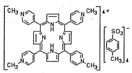
特に、金属層を構成する金属が、表面プラズモン共鳴(SPR)効果を発揮できる金等を用いる場合には、前記金等に自己吸着(自己組織化)する性質を有するイオウ化合物を用いることが、より好ましい態様である。前記イオウ化合物が、金属層表面に自己吸着(自己組織化)することにより、金属層表面に、緻密な単分子膜(単分子層)を形成し、これにより、金属層表面に光を照射した際に、色素増感効率を向上させることができ、更に前記SPR効果と相まって、より大きな光電変換効率に優れた光電変換素子を得ることができる。
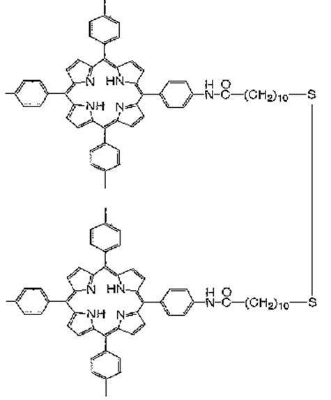
前記イオウ化合物である色素分子としては、ジスルフィド結合やチオール基等を有するイオウ化合物であり、このイオウ化合物が色素分子をも取り込んだ化合物が挙げられる。前記イオウ化合物としては、具体的には、下記化学式2~8が挙げられる。


前記色素分子を金属層に吸着・固定化するためには、前記色素分子含有溶液を用いて、前記色素含有溶液に、金属層を形成した高分子電解質を、浸漬する方法を採用することができる。前記色素分子を溶解する溶媒としては、特に制限されないが、色素分子が溶解する溶媒であることが好ましい。また、前記色素含有溶液の濃度としては、金属層を構成する金属や、色素分子により異なるが、例えば、0.01~0.50重量%が好ましく、0.03~0.30重量%がより好ましく、0.05~0.15重量%が特に好ましい。前記範囲内であれば、十分に金属層表面に、色素分子を吸着・固定化することができる。
(iv)色素分子吸着後の膨潤工程
(電解液)
本発明の光電変換素子は、電解液により、高分子電解質(層)及び、色素分子が吸着した金属層が膨潤・充填した状態にあることが好ましい。膨潤(及び充填)状態とすることにより、高分子電解質表面の金属層だけでなく、内部の金属層にまで、光が透過(到達)し、色素増感効果やSPR効果を効率よく、向上させることができ、有用である。なお、前記色素分子の吸着工程において使用される色素分子含有溶液により、色素分子の金属層への吸着と共に、膨潤工程を兼ねても構わない。なお、前記電解液(もしくは色素分子含有溶液)に使用される溶媒としては、色素分子を溶解できるものであり、更に金属層をも膨潤できる溶媒であることが好ましい。
(電解液)
本発明の光電変換素子は、電解液により、高分子電解質(層)及び、色素分子が吸着した金属層が膨潤・充填した状態にあることが好ましい。膨潤(及び充填)状態とすることにより、高分子電解質表面の金属層だけでなく、内部の金属層にまで、光が透過(到達)し、色素増感効果やSPR効果を効率よく、向上させることができ、有用である。なお、前記色素分子の吸着工程において使用される色素分子含有溶液により、色素分子の金属層への吸着と共に、膨潤工程を兼ねても構わない。なお、前記電解液(もしくは色素分子含有溶液)に使用される溶媒としては、色素分子を溶解できるものであり、更に金属層をも膨潤できる溶媒であることが好ましい。
前記電解液(膨潤溶液)としは、非水系(有機系)電解液であっても良いし水系電解液であってもよい。また、前記高分子電解質中に電解液の溶媒分子を若干含んだ状態であっても良い。なお、電解液として、水を使用した場合には、光電変換素子の充電・放電過程での金属層の金属のイオン化もしくは腐食による変質劣化を防止するために、金属層を構成する金属としては、貴金属を用いることが好ましく、特に、表面プラズモン共鳴(SPR)効果を発揮するためには、金、銀、銅を用いることが好ましく、より好ましくは金である。一方、溶媒として、非水系の極性液体を用いることもできる。高い誘電率、分解電圧を有する非水系の極性液体を溶媒とした場合には、電位窓が広がり、電気分解が起こりにくくなり、電気化学的に安定になるため、耐電圧が高くなり、エネルギー密度が大きくなる。また、非水の極性液体を溶媒にすれば、水を溶媒とした場合には光電変換素子の電極として使用が難しかった金などの貴金属以外の金属(例えば、銅等)を電極とすることができ、コスト面においても有利である。
前記非水系の電解液に含まれる溶媒として、具体的には、プロピレンカーボネイト、N-メチルピロリドン、ジメチルスルホキシド、アセトニトリル、N,N-ジメチルホルムアミド、N-メチルホルムアミド(NMF)、テトラヒドロフラン(THF)、ヘキサメチルリン酸トリアミド、γ-ブチロラクトン、1,2-ジメトキシエタン、N-メチルアセトアミド、スルホランエチレンカーボネイト、グルタロニトリル、アジポニトリル、ニトロメタン、ニトロエタン、ピリジン、好ましくは、プロピレンカーボネイト、n-メチルピロリドン、ジメチルスルホキシド、N-メチルホルムアミド、γ-ブチロラクトン、更に好ましくはプロピレンカーボネイト、N-メチルホルムアミド、γ-ブチロラクトン、1,4-ジオキソランなどの非水の極性液体を挙げることができ、特に好ましい極性液体として、N-メチルホルムアミド(NMF)、テトラヒドロフラン(THF)を挙げることができる。
前記溶媒として、N-メチルホルムアミド(NMF)とテトラヒドロフラン(THF)を混合して使用することも可能である。たとえば、NMF:THF(体積比)を10:90~35:65が好ましく、15:85~30:70がより好ましく、20:80~25:75が特に好ましい混合割合である。NMFの量が前記割合より少ないと、十分に膨潤することができず、一方、NHFの配合割合が前記割合よりも多いと、膨潤しすぎ、高分子電解質表面及び/又は内部に形成されている金属層が脱離し、金属層が得られないことになり、好ましくない。
また、前記電解液として、上記電解液だけでなく、たとえば、分子量50~400のエーテル基含有化合物を含有することができ、より好ましくは、分子量が100~300である。たとえば、ポリエチレングリコール(PEG)や、グリセロールカーボネート、ジエチレングリコールモノエチルエーテル、トリエチレングリコールモノブチルエーテル、及び、これらの類縁化合物からなる群より選択される少なくとも1種を含むことが好ましく、より好ましくは、PEGや、グリセロールカーボネートを含むことである。前記PEG等の化合物を電解液に含有させることにより、イオン伝導性が良好となり、通電性が向上し、光電流が大幅に増大するため、好ましい。特に本発明においては、前記エーテル基含有化合物に、以下に説明する電子受容体や酸化還元対、電解質塩を配合・溶解することにより、より優れた光電変換効率を有する光電変換素子を得ることができ、有効である。また、前記エーテル基含有化合物が不揮発性である場合には、長期間電解液を補充する必要がない等、作業性や耐久性にも優れたものとなる。更に、PEG等は、金属層を形成した高分子電解質(高分子電解質-金属層複合体)をも、膨潤させることができ、有用である。なお、電解液中の前記PEG等のエーテル基含有化合物の含有量としては、その他の溶媒に対する溶解限度まで、配合することができる。なお、分子量の測定方法は、ゲル透過性評価に基づくものである。
上記電解液により膨潤させる際の、膨潤度としては、5~50%が好ましく、10~35%がより好ましい。前記範囲内にあると、金属層(金属電極)構造が、金属層形成時の状態を維持しやすくなり、安定な光電変換が可能となり、好ましい。
本発明の光電変換素子は、前記電解液が、電子受容体及び/又は酸化還元対を含有することが好ましい。
前記電子受容体としては、公知のものを特に制限なく使用できるが、太陽電池等の分野において使用できるビオローゲン類や、さらに卑な酸化還元電位を有するキノン類や、アロキサジン類あるいはそれらの組み合わせを用いることができ、特に、ビオローゲン類を用いることが好ましい。前記電子受容体を使用することにより、効率の良い電荷分離が可能となり、有用である。
前記酸化還元対としては、公知のものを特に制限なく使用できるが、太陽電池等の分野において使用できるフェロセン誘導体等を用いることができ、特にフェロセニルアルコールを用いることが好ましい。前記酸化還元対を使用することにより、外部回路から光電変換素子(複合体)の金属電極(金属層)を介して、内部の高分子電解質(層)に可逆的な電子の流出入を可能とするため、永続的な光起電力を得ることが出来るようになり、有用である。
本発明の光電変換素子は、前記電解液が、電解質塩を含むことが好ましい。前記電解質塩を含有することにより、通電性が良好となり、内部抵抗の低減等の点で、有効となる。前記電解質塩は、特に限定されるものではないが、例えば、ナトリウム、リチウム、セシウム、及び、ルビジウムからなる群より選択される少なくとも1種のアルカリ金属のハロゲン化物(フッ化物、塩化物、臭化物等)や水酸化物が挙げられ、好ましくは、過塩素酸ナトリウムや、塩化セシウム、水酸化セシウム、塩化リチウム、フッ化リチウム等であり、特に好ましくは、塩化セシウムや、塩化リチウム等である。
前記電解液に含まれる電子受容体、酸化還元対、及び、電解質塩は、単独で使用してもよく、混合してもよいが、前記電解液中の含有量としては、好ましくは、0.1~10.0mol/lであり、より好ましくは、0.2~5.0mol/lである。前記範囲内にあると、通電性が向上し、光電変換の点で有用である。
本発明の光電変換素子は、金属層が対をなして形成されている場合には、光電変換素子の構成そのままで、色素増感型の太陽電池として使用することができる。特に前記光電変換素子中を不揮発性溶媒(溶液)とで満たすことにより、シールドなしの太陽電池を形成することができ、コスト面、作業性の面でも有用なものとなる。
以下、本発明の実施例及び比較例は、下記の方法により、光電変換素子を形成した。なお、本発明は下記実施例等により、限定されるものではない。
<実施例1>
(前処理工程とメッキ工程)
乾燥時の膜厚が110μmの膜状高分子電解質(フッ素樹脂系イオン交換樹脂:パーフルオロカルボン酸樹脂、商品名「フレミオン」、旭硝子社製、イオン交換容量:1.44meq/g)について、それぞれ下記(1)~(4)の工程を実施した。
(前処理工程とメッキ工程)
乾燥時の膜厚が110μmの膜状高分子電解質(フッ素樹脂系イオン交換樹脂:パーフルオロカルボン酸樹脂、商品名「フレミオン」、旭硝子社製、イオン交換容量:1.44meq/g)について、それぞれ下記(1)~(4)の工程を実施した。
(1)前処理工程:乾燥時の膜厚110μmの膜状高分子電解質(フッ素樹脂系イオン交換樹脂:パーフルオロカルボン酸樹脂、商品名「フレミオン」、旭硝子社製、イオン交換容量1.44meq/g)を膨潤溶媒であるエタノール中に20℃で30分以上浸漬した。膨潤した前記膜状高分子電解質の膜厚を測定して、乾燥膜厚に対して膨潤後の膜厚の増加した割合(膨潤度(%))を算出し、膨潤度が50%になるように前記膜状高分子電解質を膨潤溶媒に浸漬した。
(2)吸着工程:1.1重量%のジクロロフェナントロリン金塩化物水溶液に12時間浸漬し、前記高分子電解質中(表面を含む)にジクロロフェナントロリン金錯体を吸着させ、黄色化した膜を多量の水で洗浄し、余分な前記水溶液を除去して、金属錯体吸着高分子電解質を得た。
(3)還元工程:次に、前記高分子電解質を、50℃の水中に浸漬した状態で、酢酸を用いて、pH6.0に調製した後、20重量%の亜硫酸ナトリウム水溶液10mlを5時間かけて滴下したとこころ、吸着したジクロロフェナントロリン金錯体を還元して、膜状高分子電解質表面及び内部にナノ構造の金電極を形成した。このとき、水溶液の温度を60~80℃とし、亜硫酸ナトリウムを段階的に添加しながら、6時間ジクロロフェナントロリン金錯体の還元を行った。
(4)洗浄工程:表面に金電極が形成した膜状高分子電解質を取り出し、70℃の水で1時間洗浄して、高分子電解質-金属層複合体を得た。この場合、高分子電解質に含まれるイオン種は亜硫酸ナトリウム由来のナトリウムイオンとなる。なお、得られた金属層(金電極)が形成された表面抵抗は、数Ω/cmの高分子電解質-金属層複合体であった。
(2)吸着工程:1.1重量%のジクロロフェナントロリン金塩化物水溶液に12時間浸漬し、前記高分子電解質中(表面を含む)にジクロロフェナントロリン金錯体を吸着させ、黄色化した膜を多量の水で洗浄し、余分な前記水溶液を除去して、金属錯体吸着高分子電解質を得た。
(3)還元工程:次に、前記高分子電解質を、50℃の水中に浸漬した状態で、酢酸を用いて、pH6.0に調製した後、20重量%の亜硫酸ナトリウム水溶液10mlを5時間かけて滴下したとこころ、吸着したジクロロフェナントロリン金錯体を還元して、膜状高分子電解質表面及び内部にナノ構造の金電極を形成した。このとき、水溶液の温度を60~80℃とし、亜硫酸ナトリウムを段階的に添加しながら、6時間ジクロロフェナントロリン金錯体の還元を行った。
(4)洗浄工程:表面に金電極が形成した膜状高分子電解質を取り出し、70℃の水で1時間洗浄して、高分子電解質-金属層複合体を得た。この場合、高分子電解質に含まれるイオン種は亜硫酸ナトリウム由来のナトリウムイオンとなる。なお、得られた金属層(金電極)が形成された表面抵抗は、数Ω/cmの高分子電解質-金属層複合体であった。
(色素分子吸着工程)
続いて、前記複合体を、前記化学式2に示す構造のジスルフィド型ポルフィリン色素分子を含有する溶液(NMF:THF=20:80(体積比))0.5mmol/lに、50℃で1時間浸漬し、金属層(金電極)表面に、色素分子を自己吸着させ、続いて、室温に戻して、THF中に浸漬して、吸着しなかった余剰の色素分子を除去した。なお、THFにより、膨潤度30%の複合体を得た。
続いて、前記複合体を、前記化学式2に示す構造のジスルフィド型ポルフィリン色素分子を含有する溶液(NMF:THF=20:80(体積比))0.5mmol/lに、50℃で1時間浸漬し、金属層(金電極)表面に、色素分子を自己吸着させ、続いて、室温に戻して、THF中に浸漬して、吸着しなかった余剰の色素分子を除去した。なお、THFにより、膨潤度30%の複合体を得た。
(光電変換素子の製造工程)
前記膨潤した複合体は、色素分子の溶出がなく、色素分子が金微粒子やフラクタル構造等を形成したナノ構造(金属微細構造)の金属層(金電極)表面に、強く吸着(固着)した金属層が対を形成している高分子電解質-金属層-色素分子複合体、つまりは光電変換素子Aを得ることができた。前記光電変換素子Aを図1(SEM写真:倍率800倍)に示した。なお、SEM写真撮影に際しては、前記光電変換素子Aを厚さ方向に対し垂直方向に切断して、断面を切り出し、切り出された断面にSEM観察のための所定の処理を施した後、前記断面をSEM写真により観察した。
前記膨潤した複合体は、色素分子の溶出がなく、色素分子が金微粒子やフラクタル構造等を形成したナノ構造(金属微細構造)の金属層(金電極)表面に、強く吸着(固着)した金属層が対を形成している高分子電解質-金属層-色素分子複合体、つまりは光電変換素子Aを得ることができた。前記光電変換素子Aを図1(SEM写真:倍率800倍)に示した。なお、SEM写真撮影に際しては、前記光電変換素子Aを厚さ方向に対し垂直方向に切断して、断面を切り出し、切り出された断面にSEM観察のための所定の処理を施した後、前記断面をSEM写真により観察した。
(光電変換素子の製造工程)
前記光電変換素子A(金属層が対を形成)を中心部で、裁断して、片面のみに金属層を有する光電変換素子Bとした。前記片面のみに金属層を有する光電変換素子Bの電極(作用極)表面を、表1記載の組成の電解液と接触(浸漬・膨潤)させ、前記電極上の電解液と接触しない部分(端部)と、電解液中に挿入された対極(Pt板)を導線で繋ぎ、Ag/AgCl(飽和KCl)電極を参照極として、図2に示す装置(電気化学セル)になるように、ITOで金属層側を封止した。光電変換素子Bの水溶液側(ITOとは反対側)から単色光の照射(日本分光株式会社製、XeハイパーモノライトHM-250Q型、400nm)を行い、前記作用極-対極間に誘起される電流、いわゆる光電流(フソー社製、ポテンショスタット Huso HECSにより測定)を、照射した単色光の波長と単位面積あたり入射光エネルギーあたりの値としてプロットし、図3に示される、いわゆる光電流アクションスペクトルを得た。なお、ITOを使用する理由としては、ITOが、光透過性に優れており、また電解液(ここでは電解質水溶液)の透過を遮断(漏れ防止)すると共に本発明における金属層と共に金属電極の一部として、利用できるためである。また、本発明において、光電流アクションスペクトルとは、単なる光電流ではなく、色素増感効果や、SPR効果に基づく光電流を含むことを意味する。なお、本発明においては、光源から試料(電気化学セル等)に対して、一定の距離で、光照射を行っている。
前記光電変換素子A(金属層が対を形成)を中心部で、裁断して、片面のみに金属層を有する光電変換素子Bとした。前記片面のみに金属層を有する光電変換素子Bの電極(作用極)表面を、表1記載の組成の電解液と接触(浸漬・膨潤)させ、前記電極上の電解液と接触しない部分(端部)と、電解液中に挿入された対極(Pt板)を導線で繋ぎ、Ag/AgCl(飽和KCl)電極を参照極として、図2に示す装置(電気化学セル)になるように、ITOで金属層側を封止した。光電変換素子Bの水溶液側(ITOとは反対側)から単色光の照射(日本分光株式会社製、XeハイパーモノライトHM-250Q型、400nm)を行い、前記作用極-対極間に誘起される電流、いわゆる光電流(フソー社製、ポテンショスタット Huso HECSにより測定)を、照射した単色光の波長と単位面積あたり入射光エネルギーあたりの値としてプロットし、図3に示される、いわゆる光電流アクションスペクトルを得た。なお、ITOを使用する理由としては、ITOが、光透過性に優れており、また電解液(ここでは電解質水溶液)の透過を遮断(漏れ防止)すると共に本発明における金属層と共に金属電極の一部として、利用できるためである。また、本発明において、光電流アクションスペクトルとは、単なる光電流ではなく、色素増感効果や、SPR効果に基づく光電流を含むことを意味する。なお、本発明においては、光源から試料(電気化学セル等)に対して、一定の距離で、光照射を行っている。
<比較例1>
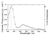
実施例1と同様な装置構成にて、本発明の光電変換素子Bを使用するのではなく、ITO電極上に、スパッタリングにより、厚み0.2μmの金を蒸着して形成された金電極(金メッキ層)に、塩化メチレンに実施例1で使用した色素分子を溶解・吸着させ、これを光電変換素子Cとした。前記光電変換素子Cの電解液側から白色光の照射(日本分光株式会社製、XeハイパーモノライトHM-250Q型、380~1200nm)を行い、光電流アクションスペクトル、更には吸光度の測定を行った。前記スペクトル及び吸光度の測定結果(グラフ)を図4に示した。比較例1においては、窒素置換を行って測定した結果を使用している。これは、酸素存在下では、光電流を明確なスペクトルとして、とらえることができなかっためである。一方、実施例全てにおいて、脱気(窒素置換)等行わず、酸素存在下(過酷な条件下)であっても、光電流アクションスペクトルを評価することができた。なお、本発明における白色光とは、380~1200nmの波長域を指し、紫外光~可視光~近赤外光領域を含むことを意味する。
実施例1と同様な装置構成にて、本発明の光電変換素子Bを使用するのではなく、ITO電極上に、スパッタリングにより、厚み0.2μmの金を蒸着して形成された金電極(金メッキ層)に、塩化メチレンに実施例1で使用した色素分子を溶解・吸着させ、これを光電変換素子Cとした。前記光電変換素子Cの電解液側から白色光の照射(日本分光株式会社製、XeハイパーモノライトHM-250Q型、380~1200nm)を行い、光電流アクションスペクトル、更には吸光度の測定を行った。前記スペクトル及び吸光度の測定結果(グラフ)を図4に示した。比較例1においては、窒素置換を行って測定した結果を使用している。これは、酸素存在下では、光電流を明確なスペクトルとして、とらえることができなかっためである。一方、実施例全てにおいて、脱気(窒素置換)等行わず、酸素存在下(過酷な条件下)であっても、光電流アクションスペクトルを評価することができた。なお、本発明における白色光とは、380~1200nmの波長域を指し、紫外光~可視光~近赤外光領域を含むことを意味する。
比較例1の図4には、実施例1の図3に示されるような色素分子に基づく色素増感効果に相当する光吸収の小さい領域、例えば670nm付近での大きな光電流を認めることが出来ず、表面(局在)プラズモン共鳴(SPR)効果による光電流の増幅効果が著しく小さいことが判明した。このことから、実施例1の光電変換素子のナノ構造金電極が、SPR効果により、光電流の増幅効果が顕著であることが判明した。
<比較例2>
実施例1における色素分子吸着工程において、前記ジスルフィド型ポルフィリン色素溶液(NMF:THF=20:80(体積比))中のNMFとTHFの体積比を、NMF:THF=42:58とし、高分子電解質-金属層複合体を膨潤(膨潤度70%)させ、更にTHF中に浸漬して、余剰の色素分子を除去する作業を行ったところ、金属層を構成する金微粒子が、高分子電解質表面及び/又は内部から脱離してしまい、表面抵抗値が1kΩ/cm以上となり、高分子電解質-金属層複合体を維持できなかった。また、前記複合体を用いて、そのまま光電変換素子として、実施例1同様に、光電流アクションスペクトルを測定したところ、光電変換機能の発現が著しく困難となることが判明した。
実施例1における色素分子吸着工程において、前記ジスルフィド型ポルフィリン色素溶液(NMF:THF=20:80(体積比))中のNMFとTHFの体積比を、NMF:THF=42:58とし、高分子電解質-金属層複合体を膨潤(膨潤度70%)させ、更にTHF中に浸漬して、余剰の色素分子を除去する作業を行ったところ、金属層を構成する金微粒子が、高分子電解質表面及び/又は内部から脱離してしまい、表面抵抗値が1kΩ/cm以上となり、高分子電解質-金属層複合体を維持できなかった。また、前記複合体を用いて、そのまま光電変換素子として、実施例1同様に、光電流アクションスペクトルを測定したところ、光電変換機能の発現が著しく困難となることが判明した。
<比較例3>
また、比較例2と同様に、今度はNMFとTHFの体積比を、NMF:THF=5:95としたところ、前記複合体の膨潤がほとんど起こらず、結果として色素の吸着量が、実施例1(単色光400nmを照射時の光電流値:219nA/cm2)に比べて、10分の1以下(単色光400nmを照射時の光電流値:18nA/cm2)となり光電変換素子としての機能が実用レベルに達しなかった。
また、比較例2と同様に、今度はNMFとTHFの体積比を、NMF:THF=5:95としたところ、前記複合体の膨潤がほとんど起こらず、結果として色素の吸着量が、実施例1(単色光400nmを照射時の光電流値:219nA/cm2)に比べて、10分の1以下(単色光400nmを照射時の光電流値:18nA/cm2)となり光電変換素子としての機能が実用レベルに達しなかった。
<実施例2>
実施例1の光電変換素子Aを表1に示す組成の電解液に、50℃で1時間浸漬した後、引き上げて、水分が乾かないように素早く片側にITOを透明電極とするように、して、厚さ約2mmのITO2枚を、光電変換素子Aを密着させて、挟み込みこむように構成し、片側のITO(透明電極)を作用極とし、対となる反対側のITOを対極とし、これをセルとした。前記作用極側から白色光の照射(日本分光株式会社製、XeハイパーモノライトHM-250Q型、380~1200nm)を行い、前記作用極-対極間に誘起される電流、いわゆる光電流(フソー社製、ポテンショスタット Huso HECSにより測定)を、光電流アクションスペクトルとして測定し、この結果(グラフ)を図5に示した。
実施例1の光電変換素子Aを表1に示す組成の電解液に、50℃で1時間浸漬した後、引き上げて、水分が乾かないように素早く片側にITOを透明電極とするように、して、厚さ約2mmのITO2枚を、光電変換素子Aを密着させて、挟み込みこむように構成し、片側のITO(透明電極)を作用極とし、対となる反対側のITOを対極とし、これをセルとした。前記作用極側から白色光の照射(日本分光株式会社製、XeハイパーモノライトHM-250Q型、380~1200nm)を行い、前記作用極-対極間に誘起される電流、いわゆる光電流(フソー社製、ポテンショスタット Huso HECSにより測定)を、光電流アクションスペクトルとして測定し、この結果(グラフ)を図5に示した。
前記図5から光電流(光電流アクションスペクトル)値の絶対値は、図3の4分の1程度に減少しているが、スペクトル形状が酷似していることから、光電変換素子の対向する金属層(金属電極)間に光電流が流れ、しかもITOと接触する面から遠い樹脂(高分子電解質)内部にて、光電荷分離が起こったことが推定される。
そこで、前記光電変換素子(セル)を、人工光源(分光計器社製、疑似太陽光源OTENTO-SUNII分光計器、Xe光)を用いた太陽電池特性評価装置にかけて、作用極側のITO上面から光照射し、その際のI-V特性を測定し、その結果(グラフ)を図6の結果を得た。前記図6より、光電変換素子(セル)内に、従来の太陽電池で使用されている共役する酸化還元対が存在しないにも関わらず、光電変換素子の両電極間に約80mVの起電力(光起電力)が生じ、太陽電池として機能することが明らかとなった。
<実施例3>
実施例2において電解液中の水をPEG(分子量200)に置き換えた以外は、同様の組成にて、評価した。なお、実施例3においては、実施例2で使用していたITO電極を除いた状態(端部に導通金属を接触させて複合体膜の対向電極間に電圧を印加)で、白色光(日本分光株式会社製、XeハイパーモノライトHM-250Q型、380~1200nm)を照射し、光電流(光電流アクションスペクトル)の評価を行った。その評価結果から、光電流(316nA/cm2)が得られた。これに対して、近赤外領域(680~1200nm、フィルターを使用して、近赤外光だけを照射。)の光に基づく光電流(95nA/cm2)は、前記白色光照射時の約3分の1に達する光電流が観測される事が明らかとなり、ナノ構造(金属微細構造)の金属層(金電極)を有する光電変換素子を用いることにより、色素増感効果と共に、SPR効果に基づき、影響(効果)されたものと推定される。
実施例2において電解液中の水をPEG(分子量200)に置き換えた以外は、同様の組成にて、評価した。なお、実施例3においては、実施例2で使用していたITO電極を除いた状態(端部に導通金属を接触させて複合体膜の対向電極間に電圧を印加)で、白色光(日本分光株式会社製、XeハイパーモノライトHM-250Q型、380~1200nm)を照射し、光電流(光電流アクションスペクトル)の評価を行った。その評価結果から、光電流(316nA/cm2)が得られた。これに対して、近赤外領域(680~1200nm、フィルターを使用して、近赤外光だけを照射。)の光に基づく光電流(95nA/cm2)は、前記白色光照射時の約3分の1に達する光電流が観測される事が明らかとなり、ナノ構造(金属微細構造)の金属層(金電極)を有する光電変換素子を用いることにより、色素増感効果と共に、SPR効果に基づき、影響(効果)されたものと推定される。
<実施例4>
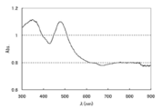
実施例3の電解液の組成に対して、表1に示すように組成を変更して、実施例3と同様な実験を行なった。この結果より、白色光を照射に基づく光電流値が3~34倍、近赤外領域に基づく光電流値が5~6倍となり、ITOを用いない光電変換素子(セル)において、光電流が電解液成分(特に電解質塩)の影響を大きく受けることが判明した。なお、実施例4における電解液の組成において、色素分子吸着前後の吸光度を測定した。色素吸着前の吸光度を図7(高分子電解質-金属層複合体)に示し、色素吸着後の吸光度を図8(光電変換素子:高分子電解質-金属層-色素分子複合体)に示した。これらの結果より、色素分子の吸着により、吸光度が向上し、つまりは、光電流の向上が図れることが明確となった。
実施例3の電解液の組成に対して、表1に示すように組成を変更して、実施例3と同様な実験を行なった。この結果より、白色光を照射に基づく光電流値が3~34倍、近赤外領域に基づく光電流値が5~6倍となり、ITOを用いない光電変換素子(セル)において、光電流が電解液成分(特に電解質塩)の影響を大きく受けることが判明した。なお、実施例4における電解液の組成において、色素分子吸着前後の吸光度を測定した。色素吸着前の吸光度を図7(高分子電解質-金属層複合体)に示し、色素吸着後の吸光度を図8(光電変換素子:高分子電解質-金属層-色素分子複合体)に示した。これらの結果より、色素分子の吸着により、吸光度が向上し、つまりは、光電流の向上が図れることが明確となった。

注)色素分子濃度:吸着液中0.5mM
過塩素酸ナトリウム濃度:0.1M
塩化セシウム濃度:1.0M
MV2+(東京化成工業社製、1,1’-ジメチル-4、4’-ピリジニウムジクロライドハイドレート、慣用名:メチルビオローゲン)濃度:0.5mM
<評価結果>
上記実施例の結果から、本発明の光電変換素子は、金属層として、比表面積の非常に大きなナノ構造を有する金属層を用いるため、色素分子の吸着による色素増感効果だけでなく、SPR効果に基づき、優れた光電変換効果(効率)を得られることが確認できた。
上記実施例の結果から、本発明の光電変換素子は、金属層として、比表面積の非常に大きなナノ構造を有する金属層を用いるため、色素分子の吸着による色素増感効果だけでなく、SPR効果に基づき、優れた光電変換効果(効率)を得られることが確認できた。
また、従来のように酸化還元対等を用いない場合であっても、太陽電池として使用できる起電力を得られることも確認できた。
更に、ITO等を使用することなく光電変換素子を製造することができ、また、ITOを使用しないことや、新規な電場増強効果(例えば、SPR効果等)により、これまでの可視領域だけではなく、近赤外領域の光線をも利用することを可能とし、光電変換効率の向上も認められた。
また、光電変換素子内部を満たす電解液中に含まれる電解質塩を、通常用いられる過塩素酸ナトリウムから、塩化セシウムに変更し、更に濃度を変更して、光電流を測定したところ、数倍~10倍程度の大きな光電流を得ることができ、高分子電解質型太陽電池として非常に有用であることが確認できた。
A: 光電変換素子A
B: 光電変換素子B
L: 光
1: 金属層(金電極)
2: 高分子電解質
3: 石英ガラス
3’:ITO
4: ポテンショスタット(電流モニター)
5: 光源
6: 対極(Pt)
7: 参照極(Ag/AgCl)
8: 作用極(金属層表面)
10:電気化学セル
B: 光電変換素子B
L: 光
1: 金属層(金電極)
2: 高分子電解質
3: 石英ガラス
3’:ITO
4: ポテンショスタット(電流モニター)
5: 光源
6: 対極(Pt)
7: 参照極(Ag/AgCl)
8: 作用極(金属層表面)
10:電気化学セル
Claims (11)
- 高分子電解質、金属層、及び、色素分子を含む光電変換素子であって、前記金属層が、前記高分子電解質と接し、かつ、前記金属層が、前記高分子電解質の表面及び/又は内部に形成されたものであり、前記色素分子が、前記金属層に吸着していることを特徴とする光電変換素子。
- 前記色素分子が、イオウ含有化合物であることを特徴とする請求項1に記載の光電変換素子。
- 前記高分子電解質が、イオン交換樹脂であることを特徴とする請求項1又は2に記載の光電変換素子。
- 電子受容体及び/又は酸化還元対を含有することを特徴とする請求項1~3のいずれかに記載の光電変換素子。
- 電解質塩を含有することを特徴とする請求項1~4のいずれかに記載の光電変換素子。
- 分子量50~400のエーテル基含有化合物を含有することを特徴とする請求項1~5のいずれかに記載の光電変換素子。
- 前記金属層が、対を形成することを特徴とする請求項1~6のいずれかに記載の光電変換素子。
- 請求項7に記載の光電変換素子であって、前記高分子電解質の外側に向かって、前記金属層を構成する金属微細構造が、リッチな領域を有し、前記高分子電解質の中心に向かって、前記高分子電解質が、リッチな領域を有することを特徴とする光電変換素子。
- 請求項1~8のいずれかに記載の光電変換素子を備える高分子電解質型太陽電池。
- 請求項1~8のいずれかに記載の光電変換素子の製造方法であって、電解メッキ方法、又は、無電解メッキ方法により、前記高分子電解質の表面及び/又は内部に、前記金属層を形成する工程と、前記金属層に、色素分子を吸着させる工程と、前記高分子電解質、及び、前記色素分子の吸着した金属層を、溶媒又は溶液により、膨潤させる工程と、を含むことを特徴とする光電変換素子の製造方法。
- 前記無電解メッキ方法が、前記高分子電解質に金属錯体を吸着させる吸着工程と、前記金属錯体が吸着した高分子電解質に還元剤溶液を接触させ、金属層を形成する還元工程と、を含むことを特徴とする請求項10に記載の光電変換素子の製造方法。
Applications Claiming Priority (2)
| Application Number | Priority Date | Filing Date | Title |
|---|---|---|---|
| JP2010032387A JP2011171051A (ja) | 2010-02-17 | 2010-02-17 | 光電変換素子、光電変換素子の製造方法、及び、高分子電解質型太陽電池 |
| JP2010-032387 | 2010-02-17 |
Publications (1)
| Publication Number | Publication Date |
|---|---|
| WO2011102423A1 true WO2011102423A1 (ja) | 2011-08-25 |
Family
ID=44483009
Family Applications (1)
| Application Number | Title | Priority Date | Filing Date |
|---|---|---|---|
| PCT/JP2011/053403 Ceased WO2011102423A1 (ja) | 2010-02-17 | 2011-02-17 | 光電変換素子、光電変換素子の製造方法、及び、高分子電解質型太陽電池 |
Country Status (2)
| Country | Link |
|---|---|
| JP (1) | JP2011171051A (ja) |
| WO (1) | WO2011102423A1 (ja) |
Cited By (2)
| Publication number | Priority date | Publication date | Assignee | Title |
|---|---|---|---|---|
| JP2013234895A (ja) * | 2012-05-08 | 2013-11-21 | Konica Minolta Inc | 太陽電池評価装置および該方法 |
| JP2014056805A (ja) * | 2012-08-10 | 2014-03-27 | Pgs Home Co Ltd | 色素増感太陽電池 |
Citations (5)
| Publication number | Priority date | Publication date | Assignee | Title |
|---|---|---|---|---|
| JPH09259943A (ja) * | 1996-03-19 | 1997-10-03 | Tokyo Gas Co Ltd | 湿式太陽電池 |
| JP2001199961A (ja) * | 2000-01-21 | 2001-07-24 | Fuji Photo Film Co Ltd | 重合性溶融塩モノマー、電解質組成物および電気化学電池 |
| JP2002299678A (ja) * | 2001-03-29 | 2002-10-11 | Fuji Photo Film Co Ltd | 高感度受光素子及び光センサー |
| JP2007335222A (ja) * | 2006-06-15 | 2007-12-27 | Ipb:Kk | 光電極、及びそれを用いた色素増感太陽電池、並びにその製造方法 |
| JP2008122439A (ja) * | 2006-11-08 | 2008-05-29 | Ricoh Co Ltd | 混合物、これを用いた光記録媒体、光電変換素子、光制限素子、及び光造形システム |
-
2010
- 2010-02-17 JP JP2010032387A patent/JP2011171051A/ja not_active Withdrawn
-
2011
- 2011-02-17 WO PCT/JP2011/053403 patent/WO2011102423A1/ja not_active Ceased
Patent Citations (5)
| Publication number | Priority date | Publication date | Assignee | Title |
|---|---|---|---|---|
| JPH09259943A (ja) * | 1996-03-19 | 1997-10-03 | Tokyo Gas Co Ltd | 湿式太陽電池 |
| JP2001199961A (ja) * | 2000-01-21 | 2001-07-24 | Fuji Photo Film Co Ltd | 重合性溶融塩モノマー、電解質組成物および電気化学電池 |
| JP2002299678A (ja) * | 2001-03-29 | 2002-10-11 | Fuji Photo Film Co Ltd | 高感度受光素子及び光センサー |
| JP2007335222A (ja) * | 2006-06-15 | 2007-12-27 | Ipb:Kk | 光電極、及びそれを用いた色素増感太陽電池、並びにその製造方法 |
| JP2008122439A (ja) * | 2006-11-08 | 2008-05-29 | Ricoh Co Ltd | 混合物、これを用いた光記録媒体、光電変換素子、光制限素子、及び光造形システム |
Cited By (2)
| Publication number | Priority date | Publication date | Assignee | Title |
|---|---|---|---|---|
| JP2013234895A (ja) * | 2012-05-08 | 2013-11-21 | Konica Minolta Inc | 太陽電池評価装置および該方法 |
| JP2014056805A (ja) * | 2012-08-10 | 2014-03-27 | Pgs Home Co Ltd | 色素増感太陽電池 |
Also Published As
| Publication number | Publication date |
|---|---|
| JP2011171051A (ja) | 2011-09-01 |
Similar Documents
| Publication | Publication Date | Title |
|---|---|---|
| Bella et al. | Aqueous dye-sensitized solar cells | |
| Wu et al. | A novel thermosetting gel electrolyte for stable quasi‐solid‐state dye‐sensitized solar cells | |
| Soo Kang et al. | Reactively sputtered nickel nitride as electrocatalytic counter electrode for dye-and quantum dot-sensitized solar cells | |
| Bella et al. | First pseudohalogen polymer electrolyte for dye-sensitized solar cells promising for in situ photopolymerization | |
| Wang et al. | A stable quasi-solid-state dye-sensitized solar cell with an amphiphilic ruthenium sensitizer and polymer gel electrolyte | |
| Benedetti et al. | Cross-linked gel polymer electrolyte containing multi-wall carbon nanotubes for application in dye-sensitized solar cells | |
| CN104903338A (zh) | 钴配合物盐 | |
| Sonigara et al. | Anisotropic one-dimensional aqueous polymer gel electrolyte for photoelectrochemical devices: improvement in hydrophobic TiO2–dye/electrolyte interface | |
| Achari et al. | A quasi-liquid polymer-based cobalt redox mediator electrolyte for dye-sensitized solar cells | |
| Khalili et al. | Comparison of chitosan and chitosan nanoparticles on the performance and charge recombination of water-based gel electrolyte in dye sensitized solar cells | |
| Kang et al. | Pt-free counter electrodes with carbon black and 3D network epoxy polymer composites | |
| Ming et al. | The potential of incorporation of binary salts and ionic liquid in P (VP-co-VAc) gel polymer electrolyte in electrochemical and photovoltaic performances | |
| Park et al. | Poly (3, 4-Ethylenedioxythiophene) inverse opal electrode fabricated from poly (3, 4-ethylenedioxythiophene): poly (styrene sulfonate)-filled polystyrene template for dye-sensitized solar cells | |
| EP1629511A2 (en) | Composite structure | |
| Mozaffari et al. | Effects of water-based gel electrolyte on the charge recombination and performance of dye-sensitized solar cells | |
| Lee et al. | Influence of different iodide salts on the performance of dye-sensitized solar cells containing phosphazene-based nonvolatile electrolytes | |
| Yoo et al. | Binary redox couples for highly transparent and high-voltage dye-sensitized solar cells | |
| JP5380851B2 (ja) | 色素増感型太陽電池の製造方法および色素増感型太陽電池モジュールの製造方法 | |
| Kim et al. | Triiodide-in-Iodine Networks Stabilized by Quaternary Ammonium Cations as Accelerants for Electrode Kinetics of Iodide Oxidation in Aqueous Media | |
| Rahman et al. | A non-absorbing organic redox couple for sensitization-based solar cells with metal-free polymer counter electrode | |
| Perganti et al. | Cost-efficient platinum-free DSCs using colloidal graphite counter electrodes combined with D35 organic dye and cobalt (II/III) redox couple | |
| Xu et al. | Custom-designed metal-free quinoxaline sensitizer for dye-sensitized solar cells based on cobalt redox shuttle | |
| JP2011171051A (ja) | 光電変換素子、光電変換素子の製造方法、及び、高分子電解質型太陽電池 | |
| Lee et al. | Novel heterologous binary redox mediator based on an ionic liquid and cobalt complex for efficient organic-solvent-free dye-sensitized solar cells | |
| JP2007317446A (ja) | 色素増感太陽電池 |
Legal Events
| Date | Code | Title | Description |
|---|---|---|---|
| 121 | Ep: the epo has been informed by wipo that ep was designated in this application |
Ref document number: 11744709 Country of ref document: EP Kind code of ref document: A1 |
|
| NENP | Non-entry into the national phase |
Ref country code: DE |
|
| 122 | Ep: pct application non-entry in european phase |
Ref document number: 11744709 Country of ref document: EP Kind code of ref document: A1 |