WO2011101901A1 - 中継装置 - Google Patents
中継装置 Download PDFInfo
- Publication number
- WO2011101901A1 WO2011101901A1 PCT/JP2010/001025 JP2010001025W WO2011101901A1 WO 2011101901 A1 WO2011101901 A1 WO 2011101901A1 JP 2010001025 W JP2010001025 W JP 2010001025W WO 2011101901 A1 WO2011101901 A1 WO 2011101901A1
- Authority
- WO
- WIPO (PCT)
- Prior art keywords
- frame
- communication device
- activation
- communication
- transmitted
- Prior art date
- Legal status (The legal status is an assumption and is not a legal conclusion. Google has not performed a legal analysis and makes no representation as to the accuracy of the status listed.)
- Ceased
Links
Images












Classifications
-
- G—PHYSICS
- G06—COMPUTING OR CALCULATING; COUNTING
- G06F—ELECTRIC DIGITAL DATA PROCESSING
- G06F1/00—Details not covered by groups G06F3/00 - G06F13/00 and G06F21/00
- G06F1/26—Power supply means, e.g. regulation thereof
- G06F1/32—Means for saving power
- G06F1/3203—Power management, i.e. event-based initiation of a power-saving mode
- G06F1/3206—Monitoring of events, devices or parameters that trigger a change in power modality
- G06F1/3209—Monitoring remote activity, e.g. over telephone lines or network connections
-
- H—ELECTRICITY
- H04—ELECTRIC COMMUNICATION TECHNIQUE
- H04L—TRANSMISSION OF DIGITAL INFORMATION, e.g. TELEGRAPHIC COMMUNICATION
- H04L12/00—Data switching networks
- H04L12/02—Details
- H04L12/12—Arrangements for remote connection or disconnection of substations or of equipment thereof
-
- H—ELECTRICITY
- H04—ELECTRIC COMMUNICATION TECHNIQUE
- H04L—TRANSMISSION OF DIGITAL INFORMATION, e.g. TELEGRAPHIC COMMUNICATION
- H04L12/00—Data switching networks
- H04L12/28—Data switching networks characterised by path configuration, e.g. LAN [Local Area Networks] or WAN [Wide Area Networks]
- H04L12/40—Bus networks
- H04L12/40006—Architecture of a communication node
- H04L12/40039—Details regarding the setting of the power status of a node according to activity on the bus
-
- Y—GENERAL TAGGING OF NEW TECHNOLOGICAL DEVELOPMENTS; GENERAL TAGGING OF CROSS-SECTIONAL TECHNOLOGIES SPANNING OVER SEVERAL SECTIONS OF THE IPC; TECHNICAL SUBJECTS COVERED BY FORMER USPC CROSS-REFERENCE ART COLLECTIONS [XRACs] AND DIGESTS
- Y02—TECHNOLOGIES OR APPLICATIONS FOR MITIGATION OR ADAPTATION AGAINST CLIMATE CHANGE
- Y02D—CLIMATE CHANGE MITIGATION TECHNOLOGIES IN INFORMATION AND COMMUNICATION TECHNOLOGIES [ICT], I.E. INFORMATION AND COMMUNICATION TECHNOLOGIES AIMING AT THE REDUCTION OF THEIR OWN ENERGY USE
- Y02D30/00—Reducing energy consumption in communication networks
- Y02D30/50—Reducing energy consumption in communication networks in wire-line communication networks, e.g. low power modes or reduced link rate
Definitions
- the present invention relates to a relay device having a remote activation technology.
- remote activation technology there is known a remote activation technology using a broadcast or multicast frame relating to a wireless LAN terminal of the IEEE 802.11 standard (for example, Japanese Patent Laid-Open No. 2005-18377 (Patent No. 409551)).
- the wireless LAN terminal when the access point transmits a frame instructing activation, the wireless LAN terminal that has received the frame turns on its own power to realize remote activation.
- Patent Document 1 does not cope with such a loss of a frame that becomes an activation signal. As a result, there is a possibility that the frame for instructing activation does not reach the terminal of the wireless LAN and the remote activation fails.
- An object of the present invention is to provide a relay apparatus that improves reachability of a frame instructing activation to a terminal to be activated and reliably achieves remote activation in a wireless communication system.
- a relay apparatus is connected to a network to be managed, receives a data frame, transmits an activation signal frame, transmits an announcement signal frame, and a first communication apparatus connected to the network.
- An activation signal generator for generating an activation signal frame for activating the first communication device when the data frame to be transmitted is received and the first communication device is not operating;
- a notification signal generation unit that generates a notification signal frame that sets a non-communication period in which a frame is not transmitted for a certain period of time with respect to the communication device to be connected, and the notification to the communication device connected to the network via the interface
- the activation signal is sent to the first communication device. It is characterized by transmitting a frame.
- a terminal to be activated can be reliably remotely activated in a wireless communication system.
- FIG. 1 is a block diagram illustrating a configuration of a relay device according to Embodiment 1.
- surface which shows an example of the information managed by the memory
- surface which shows an example of the information managed by the memory
- FIG. 6 is a block diagram illustrating a configuration of a relay device according to a second embodiment.
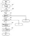
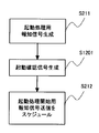
- FIG. 9 is a flowchart illustrating a flow of an operation starting from reception of a frame in a relay device according to the second embodiment.
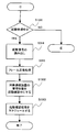
- 12 is a flowchart illustrating a flow of timer processing in the relay apparatus according to the second embodiment.
- 12 is a flowchart illustrating a flow of timer processing in the relay apparatus according to the second embodiment.
- 12 is a flowchart illustrating a flow of timer processing in the relay apparatus according to the second embodiment.
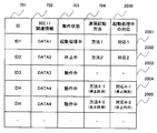
- 10 is a table showing an example of information managed by the storage unit of the relay device according to the second embodiment.
- FIG. 9 is a block diagram illustrating a configuration of a relay device according to a third embodiment.
- surface which shows an example in case priority information is preserve
- FIG. 10 is a block diagram illustrating a configuration of a relay device according to a fifth embodiment.
- FIG. 1 is a block diagram illustrating a configuration of the relay device 100 according to the first embodiment.
- the relay device 100 In an infrastructure mode wireless LAN environment, exchange of signals and data between communication devices such as wireless terminals is always performed via a relay device.
- the relay device 100 according to the present embodiment is a wireless communication relay device.
- the relay device 100 includes a communication I / F 101, a reception processing unit 102, a transmission processing unit 103, a frame storage unit 104, a determination unit 105, a connection management unit 106, a storage unit 107, a notification signal generation unit 108, and an activation signal generation unit 109. Prepare.
- the communication I / F 101 is an interface for connecting to an external network managed by the relay device 100 (hereinafter, unless otherwise specified, means a network managed by the relay device 100). More specifically, the communication I / F 101 has a function of converting a control frame, a management frame, a data frame, or the like received as a wireless signal via a network into a digital signal and passing it to the reception processing unit 102. The communication I / F 101 has a function of converting a new frame passed from the transmission processing unit 103 from a digital signal to a wireless signal and transmitting the converted signal to a network.
- the new frames passed from the transmission processing unit 103 are, for example, an activation signal frame and a notification signal frame. The activation signal frame and the notification signal frame will be described later.
- FIG. 1 shows only one communication I / F 101, but a plurality of communication I / Fs may be provided.
- a type of network to which the communication I / F 101 is connected for example, a network conforming to IEEE802.11 and a wireless LAN standard accompanying it is preferable.
- the relay device, the network, and the like comply with the IEEE 802.11 wireless LAN standard.
- the type of network is not limited to the wireless LAN standard.
- a wireless communication standard other than a wireless LAN such as Bluetooth (registered trademark) or infrared, IEEE802.3 and a wired LAN standard attached thereto, or PLC (Power Other wired communication standards such as Line Communication) may be used.
- the reception processing unit 102 processes a frame received by the communication I / F 101.
- the process for the frame is, for example, a process of checking the IEEE 802.11 header and the frame check sequence at the end of the received frame to confirm that the frame is a normal frame conforming to the IEEE 802.11 standard. .
- the frame confirmed to be a normal frame is stored in the frame storage unit 104. Further, the reception processing unit 102 instructs the determination unit 105 to determine how to handle the processed frame.
- the instruction to the determination unit 105 is performed when the frame is stored in the frame storage unit 104, and indicates the arrival of a new frame to the determination unit 105.
- the instruction to the determination unit 105 may include information (for example, a memory address or a queue identifier) that specifies a storage location of a new frame.
- the transmission processing unit 103 processes the frame stored in the frame storage unit 104 based on an instruction from the determination unit 105 into a form that can be transmitted to the network via the communication I / F 101. For example, it is a process of adding a header and a frame check sequence specified by IEEE 802.11 to a data frame to be transmitted.
- the instruction of the determination unit 105 may include information (for example, a memory address or a queue identifier) that specifies a location where a frame to be transmitted is stored.
- the processing of the communication I / F 101 and part of the processing of the reception processing unit 102 and part of the processing of the transmission processing unit 103 are closely related.
- the processes of the reception processing unit 102 and the transmission processing unit 103 must be compatible with IEEE802.11.
- the reception processing unit 102 and the transmission processing unit 103 are changed to correspond to the networks as necessary.
- the frame storage unit 104 stores a frame after reception processing, a frame before transmission, a notification signal periodically transmitted to the network, and an activation signal frame for instructing a certain communication device to perform remote activation. It is memory.
- the determination unit 105 determines processing necessary for the frame based on the frame after reception processing stored in the frame storage unit 104, and issues an instruction to each component configuring the relay device 100.
- the processes determined by the determination unit 105 include the following processes.
- Process 1 A certain process is performed by the transmission processing unit 103 on the frame stored in the frame storage unit 104, and the frame is transferred to the network via the communication I / F 101.
- Process 2 Regarding information on a communication device connected to the network, a notification is received by a frame stored in the frame storage unit 104, and connection management information of the communication device is updated based on the information.
- Process 3 An activation signal frame for activating a specific communication device connected to the network is generated.
- the process 1 is executed when relaying frames between a plurality of communication devices connected to the network and the communication device.
- the instruction destination of the process 1 is the transmission processing unit 103.
- the process 2 is a process executed when the state of the communication device connected to the network changes.
- the state changes for example, when a new communication device is connected to the network, a connection request is received from the communication device, a communication device connected to the network is disconnected, or a communication device connected to the network This is the case when the operating state has changed.
- the instruction destination of the processing 2 is the connection management unit 106. Details of the process 2 will be described later.
- the process 3 is executed when it is determined that the communication apparatus on the frame receiving side is not ready to receive a new frame when relaying the frame communication between the communication apparatuses in the process 1. Note that whether or not the communication device is ready to receive a new frame is determined based on the connection management information updated in the process 2.
- the destinations of processing 3 are the transmission processing unit 103, the notification signal generation unit 108, and the activation signal generation unit 109. Details of the process 3 will be described later.
- the judgment unit 105 has a built-in timer and manages the timer. Therefore, a schedule can be created for the time at which the notification signal frame for activation processing and the activation signal frame are transmitted to the communication device.
- the determination unit 105 performs periodic transmission of the notification signal frame and transmission of the activation signal frame at a predetermined timing according to the schedule.
- connection management unit 106 refers to the frame stored in the frame storage unit 104 based on the instruction from the determination unit 105 and manages the connection status of the communication devices connected to the network. Information managed by the connection management unit 106 and a method of using the information will be described later.
- the storage unit 107 is a memory in which the connection management unit 106 stores information necessary for managing the connection status of the communication device. Details of the information stored in the storage unit 107 will be described later.
- the notification signal generator 108 generates a notification signal frame for activation processing for transmitting the activation signal frame. Generation of a notification signal frame for activation processing is performed according to an instruction from the determination unit 105. A signal for notifying the information on the relay device 100 and the information on the network is periodically generated for the notification signal generation unit 108 and the network to which the communication I / F 101 is connected. The signal generated by the notification signal generation unit 108 (hereinafter referred to as a notification signal frame) is stored in the frame storage unit 104.
- the activation signal generation unit 109 Upon receiving an instruction from the determination unit 105, the activation signal generation unit 109 generates an activation signal frame for remotely activating a communication device connected to the network.
- the generated activation signal (hereinafter referred to as activation signal frame) is stored in the frame storage unit 104.
- the instruction from the determination unit 105 includes information necessary for generating the activation signal frame. For example, it includes an identifier (ex. MAC (Media Access Control) address or the like) for identifying a communication device to be activated.
- MAC Media Access Control
- the relay device 100 periodically fires a normal beacon that conforms to the IEEE 802.11 standard.
- This normal beacon is a management frame that does not include a QUIET element to be described later.
- the communication device 202 Soon after, the communication device 202 generates a data frame for the communication device 201 and transmits it to the relay device 100 (step S101).
- the relay apparatus 100 that has received the data frame recognizes from the management information of the communication apparatus that the operation state of the communication apparatus 201 is not in operation. Therefore, the relay device 100 generates a notification signal frame and a start signal frame for start processing (step S102).
- the relay apparatus 100 transmits a notification signal frame that notifies the start of the start processing (step S103), and transmits a start signal frame in accordance with the non-communication period set by the notification signal frame (step S104).
- the relay device 100 transfers the buffered data frame addressed to the communication device 201 to the communication device 201 (step S105). Since the relay apparatus 100 performs timer management, it is also preferable to create a schedule for the time for transmitting the notification signal frame for activation processing and the activation signal frame to the communication apparatus 201. If schedule management is used, priority processing can be easily realized when starting up a plurality of communication devices.
- FIG. 3 is a diagram illustrating an example of a frame used as an activation processing notification signal transmitted by the relay device 100 according to the first embodiment.
- a case where two notification signals are used as the activation processing notification signal will be described.
- a case where a beacon defined in IEEE 802.11 is used as a notification signal frame for activation processing will be described as an example.
- the beacon is one of management frames in the IEEE 802.11 wireless LAN standard, and includes a header 300, a body 307, and a frame check sequence (FCS) 308.
- the header 300 and the FCS 308 conform to the IEEE 802.11 specification.
- the beacon transmits information necessary for the access point (relay device) that transmits the beacon to operate the network.
- the access point for example, there are a Time stamp element 310, a Beacon interval element 311 for storing beacon transmission intervals, an SSID element 313 for storing network identification information, and the like.
- a QUIET element 314 is defined in the body 307 as one piece of information required when operating on a network.
- the QUIET element 314 instructs the communication device to suppress communication.
- the relay device 100 generates a beacon including the QUIET element 314 and transmits the beacon to the communication device. Then, the operating communication device does not communicate with the relay device 100, that is, a no-communication section is created. More specifically, the non-communication section is a section in which an operating communication apparatus does not transmit a frame for a certain period of time. An activation signal frame is transmitted during this non-communication period. Since the communication device addressed to the transmission of the activation signal frame is not affected by other communication devices, reliable remote activation can be realized.
- the QUIET element 314 is composed of six elements shown in the elements 320 to 325 in FIG. The role of each component follows the IEEE 802.11 specification, but will be briefly described as a reference.
- Element IV ID 320 is an element in which an ID for identifying the QUIET element 314 is stored.
- the Length 321 is an element that stores the length of the QUIET element 314 (excluding ID and Length), and stores the value 6.
- the Quiet Count 322 is an element that stores a value that specifies how many beacon intervals the next non-communication period starts from. For example, when “1” is stored, a non-communication period is set in a beacon interval starting from a beacon next to the beacon including the QUIET element 314.
- the Quiet period 323 is an element that stores the number of beacon intervals included in a regular no-communication period defined by the QUIET element 314. When it is “0”, no periodic communication period is set.
- the Quiet Duration 324 is an element that stores the length of the no-communication section.
- Quiet Offset 325 is an offset value from when the beacon specified by Quiet Count 322 is received to when the no-communication section is started.
- FIG. 4 is a diagram illustrating an example of a non-communication section generated by the activation processing notification signal frame.
- a beacon 401 including a QUIET element 314 is used as the activation processing notification signal frame is shown.
- a series of values relating to the elements 320 to 325 of the QUIET element 314 have a relationship as shown in FIG.
- the no-communication section Since the beacon designated to start the no-communication section has been received, the no-communication section starts after ⁇ time has elapsed since the reception of the beacon, and the length of the no-communication section is ⁇ . It can be seen that the no-communication section is set to repeat two beacon intervals.
- the length ⁇ of the non-communication section not only the time required for transmitting the activation signal frame but also a time with a slight margin. For example, it is preferable to determine in consideration of the communication method of the communication device to be activated.
- the information signal frame for starting the remote activation process and the process based on it are described.
- the broadcast signal frame for ending the remote activation process can be similarly configured using a beacon including a QUIET element.
- Quiet Duration is set to zero. Thereby, the no-communication section set in the past is discarded, and the normal state is restored.
- the Quiet Period may be set to zero.
- the no-communication section is set only once, and thereafter returns to normal operation.
- a beacon including an IEEE802.11 QUIET element is used as a notification signal associated with a remote activation process. Any other method may be used as long as it is a communication method using a notification signal including an element that functions as the QUIET element.
- the determination unit 105 instructs the connection management unit 106 to process the frame.
- the connection management unit 106 performs connection processing according to the communication method, and stores information on the communication device in the storage unit 107.
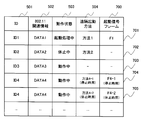
- FIG. 5 is a table showing an example of communication device information entries created in the storage unit 107.
- Communication device identification ID is an identifier for identifying each communication device connected to the network to which the relay device 100 is connected. For example, a MAC address is used as the ID.
- IEEE802.11 related information is information for managing communication devices according to the same rules.
- the “operating state of the communication device” is the state of the communication device. When the relay apparatus 100 can communicate with the communication apparatus, “in operation” is indicated. When communication with the communication device is not possible, it is a state that can be recovered in a short time with a signal from the outside, and is in a state that takes a longer time than the recovery from the suspension although it is recovered with an external signal. There is “stopped”.
- “initiating process” is set.
- the operation state of the communication device is updated when communication with the relay device 100 is successful or when a state change notification is received from each communication device.
- the relay apparatus 100 receives information indicating that it leaves the network from a certain communication apparatus, the relay apparatus 100 deletes the entry of the communication apparatus that transmitted the information from the storage unit 107.
- Communication device remote activation method is information on a remote activation method supported by the communication device. Information necessary for remote activation may be stored together with information on the remote activation method. Further, when there is a correspondence between the operating state and the remote activation method, a plurality of entries may be configured to satisfy them. If the communication device does not support remote activation, this field is left blank.
- the communication device in the row 511 of the entry in FIG. 5 is a communication device that is being activated and can be remotely activated by the method specified in “Method 1”.
- the communication device in the row 512 is a communication device that is inactive and can be remotely activated by “method 2”.
- a line 513 is a communication device that is operating and does not support remote activation.
- the communication devices in rows 514 and 515 are entries for the same communication device, but are examples of storing communication devices having different activation methods depending on the state.
- FIG. 6 is a table showing an example of information entered for “transmission time of activation signal”.
- the first flow is an operation flow starting from reception of a frame from a certain communication device.
- the first flow is, for example, a flow used for normal frame relay operation between communication devices.
- a start processing notification signal frame and a start signal frame are generated.
- a schedule for transmitting the activation processing notification signal frame and the activation signal frame is set and transmitted.
- the second flow is an operation flow related to timer management of the relay device 100.
- the second flow is an operation flow in which a notification signal frame is periodically transmitted from the relay apparatus 100 to the communication apparatus.
- the schedule for transmitting the start processing notification signal frame and the start signal frame determined in the first flow described above is managed by a timer, and the start processing notification signal frame and the start signal frame are transmitted under the timer management.
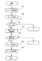
- FIGS. 8A to 8C are flowcharts showing an operation flow starting from reception of a frame of the relay apparatus 100.
- FIG. 8A to 8C are flowcharts showing an operation flow starting from reception of a frame of the relay apparatus 100.
- the reception processing unit 102 performs reception processing on the frame (step S201).
- the received frame is stored in the frame storage unit 104 (step S202).
- the determination unit 105 determines whether or not the stored frame is a data frame (step S203).
- the data frame is a frame for transmitting data such as an IP packet, for example, and is distinguished from a control frame such as a connection request frame or an arrival confirmation frame.
- a protocol consisting only of data exchange without exchanging control information
- TCP TransmissionTransControl Protocol
- UDP User Datagram Protocol
- step S203 If it is determined in step S203 that the frame is a data frame (YES in step S203), the determination unit 205 confirms the state of the destination communication device (step S204). The determination unit 205 determines whether or not the communication device designated as the reception destination of the frame is operating (step S205). This determination process is performed based on information stored in the storage unit 107. For example, referring to the operation state 503 in FIG. 5, it is determined whether or not the communication apparatus is operating.
- step S205 when the determination unit 205 determines that the communication apparatus that is the frame reception destination is operating (step S205—YES), the relay apparatus 100 transfers the frame to the communication apparatus that is the reception destination. Specifically, first, the determination unit 105 issues a transmission instruction to the transmission processing unit 103. When receiving the transmission instruction, the transmission processing unit 103 reads the frame from the frame storage unit 104 (step S206). The transmission processing unit 103 performs transmission processing on the read frame (step S207), and transmits the frame to the network via the communication I / F 101.
- step S205 determines in step S205 that the communication device that receives the frame is not operating (NO in step S205)
- the determination unit 205 It is determined whether the remote activation process is being executed (S208). If it is determined that the remote activation process is being executed (step S208—YES), the relay device 100 ends the process. At this time, since the received frame is already stored in the frame storage unit 104, it is transmitted after the remote activation process is completed.
- the determination unit 105 reads the information of the target communication device from the storage unit 107, and sets the entry of the storage unit 107 of the communication device as “activation process in progress”. (Step S209).
- the communication device When the communication device receives the frame transmitted to the target communication device by changing to “in process of activation”, the communication device buffers all the frames in the frame storage unit 104. Note that it is not always necessary to buffer all frames, and various measures can be taken depending on the implementation.
- the frame storage unit 104 may make the buffer residence time longer for data frames transmitted to a communication device during activation processing than for data frames transmitted to communication devices other than during activation processing.
- processing such as increasing the time until retransmission is attempted or increasing the number of times of retransmission may be performed. Thereby, frame loss can be further prevented.
- thresholds are set in advance for each communication device, such as increasing the buffer retention time, extending the time until frame retransmission is attempted, and increasing the number of frame retransmissions, and operate based on the threshold value. You may let them.
- the relay device 100 may operate according to the threshold value notified from the communication device.
- a notification means for the communication apparatus to notify the relay apparatus 100 of the threshold value for example, a frame for making a new connection request for the communication apparatus may be used.
- connection management unit 106 of the wireless relay device 100 finds a parameter in which the threshold value is described in the new connection request frame received from the communication device, the connection management unit 106 stores the parameter in the storage unit 107 in association with the communication device. .
- FIG. 10 is a table showing an example of storing parameters related to the activation process together as information stored and managed in the storage unit 107 by the relay device 100.
- the column 2000 “response during activation processing” in FIG. 10 correspondence with respect to a communication device during activation processing is stored, such as buffer retention time, time to attempt retransmission of a frame, threshold value of the number of frame retransmissions, and the like.
- the determination unit 105 instructs the activation signal generation unit 109 to generate an activation signal frame together with information stored in the entry corresponding to the communication apparatus that is the frame reception destination.
- the activation signal generation unit 109 generates an activation signal frame (step S210) and stores it in the frame storage unit 104.
- the determination unit 105 instructs the notification signal generation unit 108 to generate a notification signal frame for activation processing. This is to create a communication state suitable for stably transmitting the activation signal frame.
- the notification signal generation unit 108 generates a notification signal frame for activation processing (step S211) and stores it in the frame storage unit 104.
- the communication method is a communication method in which the start and end of the section for transmitting the start signal frame can be indicated by different start processing notification signals
- the notification signal generation unit 108 notifies the start processing start notification signal.
- two start processing notification signals that is, a start processing end notification signal.
- the notification signal generation unit 108 may generate only the notification signal for starting the activation process.
- the determination unit 105 sets a schedule for transmitting the activation process notification signal frame and the activation signal frame at appropriate timing (steps S212 and S213), and ends the process. For example, when the communication method only needs to generate the notification signal frame for starting the activation process, first, a transmission schedule for the notification signal for starting the activation process is set (step S212), and then the transmission of the activation signal frame is performed. A schedule is established (step S213).
- the entry corresponding to the communication device to which the frame is transmitted is updated in the storage unit 107. Note that the activation processing notification signal frame and the activation signal frame are transmitted based on timer management described later.
- the operation state of the entry in FIG. 5 is changed from “starting process” to “operating”.
- the transfer of the frame buffered in the frame storage unit 104 to the communication device that is the frame reception destination is resumed. If processing such as increasing the buffer buffer retention time or buffer length during the communication device startup process is performed, the normal frame buffer retention time and buffer length for the communication device operating state Return to.
- step S203 when the frame is not a data frame (step S203—NO), the determination unit 205 determines whether the frame is a connection request (or an update request) (step S214). When the request is not a connection request (step S214—NO), the relay device 100 performs a specified process for each control frame (step S220), and ends the process.
- the determination unit 205 determines whether or not the connection request is new (step S215). When information indicating whether or not the frame is new is stored in the frame, the determination unit 205 makes a determination with reference to the information. If the frame does not store information on whether or not the frame is new, it is determined based on whether or not information on the communication device that is the target of the received frame is stored in the storage unit 107. If the request is a new connection request (step S215-YES), an entry for storing information of the target communication device is created in the storage unit 107 (step S216). If it is not a new connection request (step S215-NO), no new entry is created.
- the relay device 100 performs a connection process for the communication device that transmitted the connection request (step S217).
- the determination unit 105 determines whether or not information related to remote activation is included in the connection request (step S218). If the connection request includes information related to remote activation (step S218—YES), the entry is updated using the information related to remote activation (step S219). On the other hand, if the information regarding remote activation is not included (step S218—NO), the process is terminated.
- the second flow is an operation flow in which a notification signal frame is periodically transmitted from the relay apparatus 100 to the communication apparatus.
- the schedule for transmitting the start processing notification signal frame and the start signal frame determined in the first flow described above is managed by a timer, and the start processing notification signal frame and the start signal frame are transmitted under the timer management.
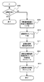
- FIGS. 9A to 9C are flowcharts showing the flow of operations caused by the timer of the relay device 100.
- FIG. 9A to 9C are flowcharts showing the flow of operations caused by the timer of the relay device 100.
- the process waits until the timer times out (steps S301 to S302).
- the determination unit 105 determines whether or not the time-out timing is the timing for transmitting the notification signal frame (step S303). If it is time to transmit the notification signal frame in step S303 (step S303—YES), the determination unit 105 determines whether to transmit a normal notification signal frame or an activation processing notification signal frame. (Step S304). If it is determined that a normal notification signal frame is to be transmitted (YES in step S304), the relay device 100 reads the notification signal created and stored in advance in the frame storage unit 302, performs transmission processing, and transmits the notification signal to the network. (Steps S305 to S306).
- the notification signal for the activation process uses a notification signal for informing the start of the activation process and a notification signal for informing the end of the activation process, and only a notification signal for informing the start of the activation process. After the elapse, the relay apparatus 100 may return to normal operation.
- the determination unit 105 transmits a notification signal frame indicating the start of the activation process or transmits a notification signal complaint indicating the end of the activation process. Whether or not (step S307).
- the relay device 100 reads the activation process start notification signal frame from the frame storage unit 104 and transmits it. (Steps S308 to S310).
- the relay device 100 reads out and transmits the activation process end notification signal frame from the frame storage unit 104 ( Steps S311 to S313).
- step S303 determines in step S303 that it is not the timing to transmit the notification signal frame (NO in step S303)
- the relay device 100 reads the activation signal frame from the frame storage unit 104 and transmits the frame (104). Steps S314 to S315). Thereafter, the determination unit 100 schedules transmission of a notification signal frame indicating that the activation process has been completed (step S316), and deletes the transmitted activation signal frame from the frame storage unit 104 (S317). Next, the operation state of the communication device that is the transmission destination of the activation signal frame is changed from “activation processing” to “in operation” (step S318), and the relay device 100 is buffered toward the communication device. A frame is transmitted (step S319).
- step S318 to S319 the process of resuming the transmission of the buffered frame (steps S318 to S319) does not have to be performed immediately after the activation signal frame is transmitted. In order to prevent frame loss, it is better to execute after a certain time after transmitting the activation signal frame.
- step S317 it has been described that the activation signal frame that has been transmitted is deleted from the storage unit 104. However, it is not necessary to delete it.
- an “activation signal frame” may be stored in association with an entry for each communication device managed by the storage unit 107 to prepare for future transmission.
- a column 700 for storing activation signal frames is provided and stored as a column 700. It can be seen that the communication apparatus of ID1 stored in the row 701 can be activated by the activation signal frame F1. Further, the communication device with ID2 stored in the row 702 is in a blank state because it is in a dormant state and has not yet generated an activation signal frame.
- the activation signal frame since the activation signal frame is transmitted to the communication apparatus in the non-communication period, the activation signal frame can be reliably transmitted to the communication apparatus. As a result, the communication apparatus can be reliably remotely activated.
- the relay device 100 can also be realized by using, for example, a general-purpose computer device as basic hardware. That is, the communication I / F 101, the reception processing unit 102, the transmission processing unit 103, the frame storage unit 104, the determination unit 105, the connection management unit 106, the storage unit 107, the notification signal generation unit 108, and the activation signal generation unit 109 This can be realized by causing a processor mounted on a computer apparatus to execute a program.
- the relay apparatus 100 may be realized by installing the above program in a computer device in advance, or may be stored in a storage medium such as a CD-ROM or distributed through the network. Thus, this program may be realized by appropriately installing it in a computer device.
- the frame storage unit 104 and the storage unit 107 appropriately use a memory, a hard disk or a storage medium such as a CD-R, a CD-RW, a DVD-RAM, a DVD-R, or the like incorporated in or externally attached to the computer device. Can be realized.
- the relay device 1100 confirms the activation of the communication device to be activated in addition to the activation of the communication device in the non-communication section by the relay device 100 according to the first embodiment.
- FIG. 11 is a block diagram illustrating the configuration of the relay apparatus 1100 according to the second embodiment.
- the components changed from the relay device 100 according to the first embodiment are a determination unit 1101 and an activation confirmation signal generation unit 1102.
- the activation confirmation signal generation unit 1102 is based on an instruction from the determination unit 1101 and is based on an instruction included in the frame stored in the frame storage unit 104 to confirm whether the communication apparatus has been activated properly. And the generated activation confirmation frame is stored in the frame storage unit 104.
- the determination unit 1101 has the following functions in addition to the functions of the determination unit 105 of the relay device 100 according to the first embodiment. First, it is a function that issues an instruction to the activation confirmation signal generation unit 1102 to generate an activation confirmation frame, and confirms whether or not the communication device to be activated is activated using the generated activation confirmation frame. is there. Secondly, when the activation target communication device is activated, the function that resumes transmission of the frame buffered in the frame storage unit 104, a state different from the normal state, such as extending the buffer buffer residence time during activation If it is, it has a function to return to the normal state.
- FIG. 12 is a flowchart showing an operation flow starting from reception of a frame by the relay apparatus 1100.
- the description of the steps for performing the same operations as in FIGS. 8A to 8C is omitted, and an operation flow unique to the second embodiment is shown.
- the flowchart of FIG. 12 differs from the flowchart of FIG. 2 in that the communication device is activated between the process of generating the notification signal frame (step S211) and the process of scheduling the transmission of the notification signal frame (step S212).
- a process for generating an activation confirmation signal frame for confirmation (step S1201) is added. The type of activation confirmation signal frame and its confirmation method will be described later.
- FIGS. 13A to 13C are flowcharts showing an operation flow caused by the timer of the relay apparatus 1100.
- FIG. Description of the steps for performing the same operation as in FIG. 9A is omitted.
- the flow of the part that transmits the activation signal frame is changed.
- step S1301 If it is not the timing to transmit the notification signal frame (NO in step S303), it is determined whether or not the communication apparatus addressed to the transmission of the frame is “starting process” (step S1301). If “starting process is in progress” (YES in step S1301), the start signal frame is read from the frame storage unit 104 and transmitted (steps S314 to S315). Next, the operation state of the communication device addressed to the transmission of the frame managed by the storage unit 107 is changed to “starting confirmation” (step S1302), and the transmission of the start confirmation frame is scheduled (step S1303).
- step S1301-NO the operation state of the target communication device is “checking start”.
- the relay apparatus 1100 performs activation confirmation processing. Specifically, the activation confirmation frame is read from the frame storage unit 104 (step S1304) and transmitted to the network (step S1305). Next, the relay device 1100 waits for a certain period of time to wait for a response signal from the target communication device to the activation confirmation frame from the target communication device (step S1306). Next, it is determined whether a response signal has been received (step S1307).
- step S1308 If there is a response signal to the activation confirmation frame from the target communication device (step S1308—YES), it is determined that the target communication device has been activated.
- the transmission of the activation process notification signal is scheduled (step S316), and the activation signal frame is deleted from the frame storage unit 104 (step S317).
- step S318 the state of the communication device managed in the storage unit 107 is changed to “operating” (step S318), and the transfer of the data frame buffered in the frame storage unit 104 is started (step S319).
- step S1308 if there is no response signal from the target communication device in step S1308 (step S1307—NO), it is checked whether the number of trials of the activation confirmation process has reached the specified number (step S1308).
- the prescribed number of times may be provided as an eigenvalue by the determination unit 105 or may be stored in the storage unit 107 and referred to by the determination unit 105 as appropriate.
- step S1308 if the activation confirmation process has reached the prescribed number of times (step S1308-YES), it is subsequently confirmed whether the activation process has reached the prescribed number of times (step S1309). Similar to the predetermined number of times related to the previous confirmation process, the predetermined number of times may be included in the determination unit 105 as an eigenvalue, or may be stored in the storage unit 107 and referred to by the determination unit 105 as appropriate.
- step S1309—YES) If the number of trials of the activation process has reached the specified number (step S1309—YES), it is determined that the communication terminal cannot be remotely activated, and the activation process is canceled. Specifically, the activation signal frame is deleted from the frame storage unit 104 (step S1310), and the entry of the communication device in the storage unit 107 is deleted (step S1311). At this time, if the determination unit 1101 can perform IP layer processing, an error response using ICMP (for example, ICMPIHost Unreachable) may be transmitted to the communication device that is the frame transmission source.
- ICMP for example, ICMPIHost Unreachable
- step S1309—NO the startup process is attempted again.
- the state included in the entry of the target communication device in the storage unit 107 is changed to “activation processing” (step S1312), and transmission of the activation signal frame is scheduled (step S1313).
- step S1308 if the activation confirmation process has not reached the specified function (NO in S1308), the process returns to step S1304 to perform the activation confirmation process again.
- the communication device to be activated notifies the relay device 1100 in advance of thresholds such as the number of activation attempts, the number of activation confirmation attempts, and the time from when the activation signal frame is transmitted until the activation confirmation is performed.
- the apparatus 1100 may operate according to the threshold value. For example, the communication apparatus notifies each threshold value by a frame for making a new connection request.
- the connection management unit 106 stores the corresponding threshold value in the corresponding entry in the storage unit 107.
- FIG. 14 shows an entry when the relay device stores each threshold value.
- entries for “number of start attempts”, “number of check attempts”, and “time until start check” are added to the management information of FIG. For example, all parameters are stored for the row (1406) representing the communication device of ID1. For the row (1407) representing the communication device of ID2, only some parameters are stored. Thus, parameters that are not supported by the communication device may be left blank.
- the activation confirmation frame is generated based on information included in the frame relayed by the relay device 1100.
- the information included in the frame is generated using, for example, a MAC address or an IP address.
- the method for confirming the activation of the communication device differs depending on the information used in the information included in the frame.
- the communication device can be confirmed for activation at the data link layer level such as IEEE 802.11.
- a protocol capable of obtaining a response at the data link layer level is used.
- IEEE 802.11 is used.
- the activation confirmation frame for example, a NULL frame defined by IEEE 802.11 is used.
- the reception destination address is the MAC address of the communication device to be activated and the transmission source address is the MAC address of the relay device. If it can be confirmed that ACK has been received as a response to the NULL frame, it is determined that the target communication device has been activated.
- the MAC address and the IP address are further used, it is possible to confirm the activation of the communication device at the IP layer level.
- an ARP packet, an ICMPAEcho Request packet, an ICMPv6 Echo Request packet, or the like is used as the activation confirmation frame.
- these are used as activation confirmation frames, it can be determined that the target communication apparatus has been activated if it can be confirmed that ARP ⁇ ⁇ ⁇ ⁇ Reply, ICMPIEcho Reply, and ICMPv6 Echo Reply have been received for each packet.
- a startup confirmation frame is generated using a MAC address and an IP address
- the network interface is operating, but if the upper layer above the network interface is not started due to a problem or the like, it can be understood and more detailed.
- the activation state of the communication device can be confirmed. In particular, when the communication device performs an operation that does not disconnect the data link layer for remote activation, it is effective to confirm activation at the IP layer.
- the packet field may be filled as follows.
- an activation confirmation frame for confirming whether or not the communication device has been activated is transmitted to the communication device to confirm whether or not the communication device has been activated.
- the data frame is transmitted to the communication device. Since the data frame is transmitted after confirmation of activation, the communication device is not activated (for example, the activation signal frame cannot be transmitted properly, or the activation processing of the communication device takes more time than expected). For example, it is possible to prevent the communication device from receiving the frame correctly. That is, the activation of the communication device can be confirmed with certainty, and the data frame can be reliably transmitted to the communication device. Also, since the data frame is transmitted after the activation is confirmed, the time until the data frame transmission is resumed more than necessary (for example, assuming that the activation process takes more time than expected). Can be prevented.
- FIG. 15 is a block diagram illustrating the configuration of the relay device according to the third embodiment.
- the storage unit 1507 stores information for identifying a frame to be preferentially processed among frames relayed by the relay device 1500, in addition to the information stored so far. This information is constructed from the various identifiers that make up the frame. For example, the source MAC address and the destination MAC address.
- the judgment unit 1505 has the capability of analyzing up to the upper layer, a source IP address, a destination IP address, a transport protocol, a TCP or UDP source port number, a destination port number, and the like can also be used.
- the information on the priority may be stored independently of the connection information of the communication device, or may be stored in an integrated form.
- FIG. 16 shows an example in which priority information is stored in the storage unit 1507 independently.
- communication identification information and priority information for three communications are stored. These communications are identified by the identifiers described above.
- the communication in the row 1611 and the communication in the row 1613 are one corresponding communication and have different directions.
- FIG. 17 shows an example in which priority information is stored in the storage unit together with connection management information of the communication device.
- connection management information columns 1701 to 1704
- priority information column 1705
- the priority information is set to “high”, “medium”, and “low”, but the granularity is not limited.
- the granularity of priority control that can be realized by the communication method may be used.
- the determination unit 1505 of the relay device 1500 appropriately converts.
- the determination unit 1505 has a function of determining whether or not to preferentially transmit the received data frame using the communication conditions to be prioritized stored in the storage unit 1507. . Based on the determination result, the contents of the instruction to be issued to the activation signal generation unit 1509 and the notification signal generation unit 108 are changed.
- an activation signal using a NAV (Network Allocation Vector) described later is generated. Instruct to send. If not, an instruction is given to transmit the activation signal frame after setting the no-communication section by the activation processing notification signal frame described so far.
- NAV Network Allocation Vector
- the activation signal generation unit 1509 also plays a role of an activation signal frame while setting a NAV in consideration of the time required for propagation of the activation signal frame and updating the NAV. And a function of generating a signal frame (corresponding to the second activation signal frame in claim 4).
- the NAV is a frame for setting a non-communication section that instructs a communication apparatus connected to the network not to transmit a frame for a certain period.
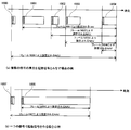
- FIG. 18 is a diagram schematically illustrating an example of the activation signal frame converted to NAV in time series.
- FIG. 18A is an example in which a set of a plurality of signals is regarded as an activation signal frame
- FIG. 18B is an example in which an activation signal frame is created with a single signal.
- the NAV is set so as to cover the entire activation signal frame.
- a frame intended to set the NAV that matches the length of the activation signal frame (for example, the frame 1806 and the frame 1807 correspond) may be separately transmitted. good.
- the activation signal frame may be generated by dividing into a plurality of frames as shown in the upper part and setting a plurality of NAVs.
- FIG. 19 is a schematic diagram illustrating a state in which a no-communication section is set when a high-priority communication signal is transmitted.
- a frame 1906 in FIG. 19 is a low-priority frame directed to a communication apparatus that is in a suspended state, and is a frame that triggers a series of remote activation.
- Frames 1900 and 1901 are activation start notification signals.
- a frame 1902 is an activation end notification signal, and a frame 1903 is a frame corresponding to high priority communication.
- a section 1904 is a non-communication section generated by the start-start notification signal of the frame 1900.
- a frame 1905 is an activation signal frame corresponding to low priority communication transmitted in the non-communication section 1904.
- a frame 1907 is a frame corresponding to high priority communication toward a communication apparatus that is in a pause state.
- a frame 1908 is an activation signal frame for activating a communication apparatus that performs communication with high priority.
- 20A to 20C show the operation flow of the relay device 1500 according to such a configuration.
- 20A to 20C are flowcharts illustrating an operation flow starting from reception of a frame in the relay device 1500 according to the third embodiment.
- step S2001 the process of performing scheduling based on priority when transferring a frame
- step S2002 to S2009 the generation and transmission process of an activation signal
- step S208—NO When a frame directed to a communication device that is not in operation is received and the communication device is not in the startup process (step S205—NO, step S208—NO), the entry status for the communication device stored in the storage unit 1507 Is changed to “being activated” (step S209). Thereafter, it is confirmed whether the received frame is to be processed preferentially or corresponds as usual (step S2002).
- step S2002-YES When the received frame is a frame to be processed as usual (step S2002-YES), the same processing as in FIG. 8B is performed. For example, assume that a series of operation flows have been executed by receiving a frame corresponding to the row 1612 in FIG. In this case, since the row 1612 is classified as a communication with low priority, the remote activation process is performed after setting the no-communication section by the notification signal as in FIG. 8B.
- the notification signal generation unit 1508 in the present embodiment does not simply perform the same operation as in FIG. 8B, but the non-communication section generated by the notification signal for starting the activation process interferes with other preferential communication. You may schedule to arrange
- the frame interval is a transmission interval of signals of high priority communication. In the figure, the transmission interval of the signal 1903 of the high priority communication is shown.
- the maximum delay is a maximum extension period from the frame interval when the signal 1903 is transmitted with an interval longer than the predetermined frame interval 1903.
- the temporal information stored in the storage unit 1507 may be stored together with the priority information shown in FIGS. Since the remote activation signal can be transmitted in such a way as to avoid the high-priority communication ascertained in advance, remote activation in a more stable manner can be realized while suppressing the influence on the high-priority communication.
- the no-communication section 1904 set by the notification signal is set to a section other than the section for transmitting the high priority signal 1903.
- the notification signal generation unit 1508 sets the no-communication section 1904 using the frame interval as temporal information. As illustrated in FIG.
- the interval is stored in the storage unit 1507.
- the notification signal generation unit 1508 refers to the interval stored in the storage unit 1507, and sets the no-communication section 1904 in a portion that does not collide with the high priority signal 1903.
- the broadcast signal generation unit 1508 sets a no-communication section 1904 set by the broadcast signal using the frame interval and the allowable maximum delay as temporal information.
- the broadcast signal generation unit 1508 sets a no-communication section 1904 in the section of the sum of the frame interval and the maximum delay.
- step S2002 processing for generating and transmitting an activation signal with the previous NAV is performed. Also, the same priority is given to the activation signal itself. For example, it is assumed that a series of operation flows has been executed by receiving a frame corresponding to the row 1611 or the row 1613 in FIG. In this case, since it is classified into a high priority, a method using an activation signal with NAV is selected, and a high priority is also given to the generated activation signal.
- an activation signal with NAV is generated and stored in the frame storage unit 104 (step S2003).
- the determination unit 1505 instructs the transmission processing unit 103 to transmit the activation signal frame in the same manner as other frames (however, with the same priority as the frame that triggered the processing).
- the transmission processing unit 103 reads the activation signal frame (step S2004), and transmits it to the network at an appropriate timing considering the priority (step S2005). Thereafter, the activation signal frame is deleted from the frame storage unit 104 (step S2006).
- step S2007 When the transmission of the activation signal frame is completed, the state of the communication device managed by the storage unit 107 is changed to “in operation” (step S2007). After that, a certain amount of time is set so that no frame loss occurs, and transmission of the frame buffered in the frame storage unit 104 is started (step S2008).
- the frame 1907 is a high-priority communication directed to the communication device that is in a pause
- the frame 1908 is a corresponding activation signal frame.
- the method for generating / transmitting the activation signal added in the third embodiment has an advantage that the activation signal frame can be transmitted at a higher speed than that in the first embodiment.
- the QoS securing method in wireless communication follows the network system to which the relay device 1500 is connected.
- a wireless LAN using IEEE802.11 can be realized by changing the transmission interval and backoff time. In other words, the higher the priority, the shorter the transmission interval and backoff time, the transmission right may be obtained.
- the activation signal when a received frame is preferentially processed, the activation signal can be transmitted to the communication apparatus at high speed and reliably by being activated using the NAV. It becomes possible. Also, when setting a no-communication section for a low priority frame, in order to set a period that does not interfere with the communication of the high priority frame, for the communication device of the transmission destination of the high priority frame, A frame with a high priority can be quickly transmitted to the communication device. As a result, the priority control policy of the entire system can be observed.
- the communication apparatus according to the fourth embodiment is an example in which the technology of the relay apparatus according to the first to third embodiments is applied to a communication apparatus that does not have a network management function.
- the relay devices of Examples 1 to 3 were devices having a function of managing a network.
- the communication device according to the fourth embodiment does not have a function of managing the network.
- the communication device according to the fourth embodiment is a communication device that configures an ad hoc network, for example.
- the communication device according to the fourth embodiment is a communication device compatible with the ad hoc network mode, and the configuration and operation of the relay device according to the first to third embodiments can be applied as they are.
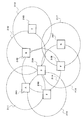
- FIG. 21 shows an ad hoc network including seven communication devices (2101 to 2107). It is assumed that the radio wave reachable range of each communication device is a portion (2111 to 2117) illustrated by a dotted line. It is assumed that the communication device grasps the optimum route to each communication device using an ad hoc routing protocol.
- the communication device A generates a packet having the communication device F2106 as a destination address, and transmits the packet to the communication device D2104.
- the communication device D2104 transfers the packet to the communication device F2106. In this way, the packet reaches the desired communication device.
- the communication device D2104 adjacent to the bag communication device F2106 transmits an activation signal to the communication device F2106, so that the communication device F2106 needs to be activated and returned to the network.
- the communication device D2104 performs the same operation as that of the relay device 100 according to the first embodiment.
- the communication device D2104 continuously manages the operating state of neighboring communication devices. For example, the information shown in FIG. 5 is managed. Note that FIG. 5 shows information managed by the access point in the infrastructure mode, but each communication device holds similar information also in the ad hoc mode.
- the operation from receiving the packet from the communication device A 2101 to transmitting the activation signal is the same as the operation shown in FIG. In FIG. 2, the relay device 100 may be read as the communication device D2104, the other communication device 202 as the communication device A2101, and the activation target communication device 201 as the communication device F2106. Therefore, the internal operation of the communication device D2104 performs the same operation as that of the relay device 100 in the first embodiment. That is, when receiving a packet from the communication device A 2101, the communication device D 2104 transmits a notification signal that notifies the start of the activation process. Then, the activation signal is transmitted to the communication device F2106 in the non-communication section set by the notification signal. After the communication device F2106 is activated, the communication device D2104 transmits a packet to the communication device F2106.
- the configuration and operation of the relay apparatus 1100 according to the second embodiment can be applied to the communication apparatus D2104. That is, the communication device D 2104 can confirm the activation of the communication device F 2106 by transmitting the activation confirmation frame to the communication device F 2106 after generating the activation signal. The packet can be transferred after confirming the activation.
- the configuration and operation of the relay device 1500 of the third embodiment can be applied to the communication device D2104. That is, the communication device D 2104 activates the communication device F 2106 based on the priority assigned to the packet received from the communication device A 2101.
- the communication apparatus is activated when the communication apparatus that is the destination of the packet is stopped.
- the present invention can be similarly applied when the communication apparatus on the route is stopped. .
- an adjacent communication device activates a communication device that is not in an operating state after setting a no-communication section, so that the communication device can be reliably activated.
- the data frame can be reliably transmitted to the communication device.
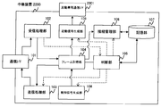
- the relay device 2200 is a relay device in which the communication interface 101 performs communication other than the activation signal, and the activation-dedicated communication interface 2201 transmits the activation signal.
- the communication interface 101 performs communication other than the activation signal
- the activation dedicated communication interface 2201 performs transmission of the activation signal.
- the communication interface 101 uses IEEE802.11.
- the activation dedicated communication interface 2201 uses the same frequency band as that of IEEE 802.11 or an overlapping frequency band, and transmits a radio wave specialized for the activation signal.
- transmission / reception of a radio frame of the communication interface 101 can be stopped when transmitting an activation signal transmitted via the activation dedicated communication interface 2201.
- transmission / reception of a radio frame of the communication interface 101 can be stopped when transmitting an activation signal transmitted via the activation dedicated communication interface 2201.
- the activation dedicated communication I / F 2201 transmits an activation signal. Also, the relay device 2200 stores the activation signal frame generated in step S210 of FIG. 8B in the activation signal generation unit 109 without storing it in the frame storage unit 104. In addition, in step S314 in FIG. 9C, the activation signal frame is not read from the frame storage unit 104, and the processing inside the activation signal generation unit 109 is performed.
- the other operations of the relay device 2200 are the same as those of the relay device 100 according to the first embodiment.
- the activation signal frame since the activation signal frame is transmitted to the communication device in the non-communication period, the activation signal frame can be reliably transmitted to the communication device. As a result, the communication apparatus can be reliably remotely activated. Further, according to the relay device of the fifth embodiment, data communication can be stopped at the time of starting signal transmission by separately providing interfaces for starting signal transmission and data communication. As a result, the activation signal frame can be transmitted to the communication device without being affected by data communication. As a result, it becomes possible to start the communication device more reliably.
- the present invention is not limited to the above-described embodiments as they are, and can be embodied by modifying the constituent elements without departing from the scope of the invention in the implementation stage.
- Various inventions can be formed by appropriately combining a plurality of constituent elements disclosed in the above embodiments. For example, some components may be deleted from all the components shown in the embodiments. Furthermore, constituent elements over different embodiments may be appropriately combined.
Landscapes
- Engineering & Computer Science (AREA)
- Theoretical Computer Science (AREA)
- Computer Networks & Wireless Communication (AREA)
- Signal Processing (AREA)
- Physics & Mathematics (AREA)
- General Engineering & Computer Science (AREA)
- General Physics & Mathematics (AREA)
- Mobile Radio Communication Systems (AREA)
Abstract
無線により通信する通信システムにおいて、起動を指示するフレームの起動する通信装置への到達性を高め、遠隔起動を確実に達成する中継装置100を提供する。中継装置100は、中継装置が管理するネットワークに接続する通信装置の1つである第1の通信装置に送信するフレームを受信した場合であって、かつ第1の通信装置が動作中でない場合に、第1の通信装置を起動する起動信号を生成する起動信号生成部109と、ネットワークに接続する通信装置に対して一定時間通信をしない無通信区間を設定する報知信号を生成する報知信号生成部108とを備え、中継装置100は、報知信号により無通信区間を設定し、無通信区間を設定した状態で、起動信号を送信する。
Description
本発明は、遠隔起動技術を備える中継装置に関する。
遠隔起動技術に関し、IEEE802.11規格の無線LAN端末に関するブロードキャストもしくはマルチキャストフレームを用いた遠隔起動技術が知られている(例えば、特開2005-18377(特許第409551号))。
その技術では、アクセスポイントが起動を指示するフレームを送信すると、そのフレームを受信した無線LAN端末が自身の電源を投入する事によって遠隔起動を実現している。
無線LANの接続が不安定な状況下において、起動を指示するフレームが、アクセスポイントと無線LAN端末間の無線区間で喪失する可能性がある。
しかしながら、特許文献1の技術では、このような起動信号となるフレームの喪失への対応がなされていない。その結果、起動を指示するフレームが無線LANの端末に届かず、遠隔起動が失敗する可能性があった。
本発明は、無線により通信する通信システムにおいて、起動させる端末への起動を指示するフレームの到達性を高め、遠隔起動を確実に達成する中継装置を提供することを目的とする。
本発明の一観点による中継装置は、管理するネットワークに接続し、データフレームを受信し、起動信号フレームを送信し、報知信号フレームを送信するインターフェイスと、前記ネットワークに接続する第1の通信装置に送信するデータフレームを受信した場合であって、かつ前記第1の通信装置が動作中でない場合に、前記第1の通信装置を起動させる起動信号フレームを生成する起動信号生成部と、前記ネットワークに接続する通信装置に対して一定時間フレームの送信をしない無通信区間を設定する報知信号フレームを生成する報知信号生成部とを備え、前記インターフェイスを介して、前記ネットワークに接続する通信装置に前記報知信号フレームを送信し、前記無通信区間を設定した状態で、前記第1の通信装置に前記起動信号フレームを送信することを特徴とする。
本発明によれば、無線通信システムにおいて、起動させようとする端末を確実に遠隔起動させることができる。
以下、本発明の実施の形態について図面を参照しながら説明する。各図において同一箇所については同一の符号を付すとともに、重複した説明は省略する。
図1は、実施例1に係る中継装置100の構成を示すブロック図である。インフラストラクチャモードの無線LAN環境においては、無線端末等の通信装置間の信号やデータのやりとりは、必ず中継装置を介して行われる。本実施例に係る中継装置100は、無線通信用の中継装置である。
中継装置100は、通信I/F101、受信処理部102、送信処理部103、フレーム記憶部104、判断部105、接続管理部106、記憶部107、報知信号生成部108、起動信号生成部109を備える。
通信I/F101は、中継装置100が管理する外部のネットワーク(以降、特に断らない限りにおいて、中継装置100によって管理されるネットワークを意味する。)に接続するためのインターフェイスである。より詳細には、通信I/F101は、ネットワークを経由し、無線信号で受信した制御フレームや管理フレーム、データフレーム等をデジタル信号へと変換して、受信処理部102へと渡す機能を備える。また、通信I/F101は、送信処理部103から渡された新たなフレームをデジタル信号から無線信号へと変換して、ネットワークに送信する機能を備える。送信処理部103から渡された新たなフレームとは、例えば、起動信号フレーム、報知信号フレームである。起動信号フレーム、報知信号フレームについては後述する。
図1では通信I/F101を1つしか示していないが、複数の通信I/Fを具備しても良い。通信I/F101が接続するネットワークの種類としては、例えば、IEEE802.11及びそれに付随する無線LAN規格に準拠したネットワークが好適である。実施例1では、中継装置、ネットワーク等は、IEEE802.11無線LAN規格に準拠したものとなっている。
尚、ネットワークの種類は、無線LAN規格用に限ることはなく、例えば、Bluetooth(登録商標)や赤外線といった無線LAN以外の無線通信規格、IEEE802.3及びそれに付随する有線LAN規格、又はPLC(Power Line Communication)といったその他の有線通信規格であってもよい。
受信処理部102は、通信I/F101で受信したフレームを処理する。フレームに対する処理とは、例えば、受信したフレームの先頭にあるIEEE802.11のヘッダと末尾にあるフレームチェックシーケンスをチェックし、IEEE802.11規格に準拠した正常なフレームであることを確認する処理である。
正常なフレームであることを確認されたフレームは、フレーム記憶部104に保存される。さらに、受信処理部102は、判断部105に対して処理後のフレームの扱いを判断するように指示を出す。
判断部105への指示は、フレーム記憶部104へフレームを保存した際に行い、判断部105に対して新たなフレームの到着を示すものである。判断部105への指示は、新たなフレームの保存場所を特定する情報(例えば、メモリのアドレスやキューの識別子)を含んでも良い。
送信処理部103は、判断部105の指示に基づき、フレーム記憶部104に保存されたフレームを、通信I/F101を介してネットワークに送信できる形に処理する。例えば、送信するデータフレームにIEEE802.11で規定されるヘッダとフレームチェックシーケンスを付加する処理である。判断部105の指示とは、送信すべきフレームが保存されていた場所を特定する情報(例えばメモリのアドレスやキュ-の識別子)を含んでも良い。
通信I/F101の処理と受信処理部102の一部の処理ならびに送信処理部103の一部の処理は密接に関連がある。IEEE802.11の通信インターフェイスを利用する場合には、受信処理部102と送信処理部103の処理はIEEE802.11に対応する必要がある。また、複数種のネットワークに接続する場合には、必要に応じて受信処理部102と送信処理部103が、それらのネットワークに対応するように変更される。
フレーム記憶部104は、受信処理後のフレームと、送信前のフレームと、定期的にネットワークに送信する報知信号と、ある通信装置に対して遠隔起動を指示する為の起動信号フレームとを記憶するメモリである。
判断部105は、フレーム記憶部104に保存された受信処理後のフレームに基づいて、当該フレームに必要な処理を決定し、中継装置100を構成する各構成要素に対して指示を出す。判断部105が決定する処理には、以下の処理がある。
処理1:フレーム記憶部104に保存されたフレームに対して送信処理部103で一定の処理を施し、通信I/F101を介してネットワークに転送する。
処理2:ネットワークに接続した通信装置の情報に関し、フレーム記憶部104に保存されたフレームによって通知を受け、当該情報に基づいて、当該通信装置の接続管理情報を更新する。
処理3:ネットワークに接続した特定の通信装置を起動するための、起動信号フレームを生成する。
処理2:ネットワークに接続した通信装置の情報に関し、フレーム記憶部104に保存されたフレームによって通知を受け、当該情報に基づいて、当該通信装置の接続管理情報を更新する。
処理3:ネットワークに接続した特定の通信装置を起動するための、起動信号フレームを生成する。
当該処理1は、ネットワークに接続する複数の通信装置と通信装置との間のフレームを中継する場合に実行される。当該処理1の指示先は、送信処理部103である。
当該処理2は、ネットワークに接続する通信装置の状態が変わった場合に実行する処理である。状態が変わる場合とは、例えば、ネットワークに新たな通信装置が接続し、当該通信装置から接続要求を受けた場合、ネットワークに接続中の通信装置が離脱する場合、ネットワークに接続中の通信装置の動作状態が変わった場合である。当該処理2の指示先は、接続管理部106である。尚、処理2の詳細については後述する。
当該処理3は、処理1において通信装置間でフレームの通信を中継する場合において、フレーム受信側の通信装置が、新たなフレームを受信できる状態ではないと判断された場合に実行される。尚、通信装置が、新たなフレームを受信できる状態であるか否かは、処理2によって更新される接続管理情報に基づいて判断する。処理3の指示先は、送信処理部103、報知信号生成部108及び起動信号生成部109である。尚、処理3の詳細については後述する。
また、判断部105は、タイマーを内蔵し、タイマー管理している。そこで、起動処理用の報知信号フレーム、起動信号フレームを通信装置に送信する時刻についてスケジュールを作成することができる。判断部105は、スケジュールにしたがって、報知信号フレームの定期的な送信、起動信号フレームの所定タイミングでの送信を実行する。
接続管理部106は、判断部105の指示に基づいて、フレーム記憶部104に保存されたフレームを参照して、ネットワークに接続する通信装置の接続状況を管理する。尚、接続管理部106が管理する情報と当該情報の利用方法については後述する。
記憶部107は、接続管理部106が通信装置の接続状況の管理に必要な情報を保存するメモリである。尚、記憶部107に保存する情報の詳細は後述する。
報知信号生成部108は、起動信号フレームを送信するための起動処理用の報知信号フレームを生成する。起動処理用の報知信号フレームの生成は、判断部105からの指示により行う。報知信号生成部108、また通信I/F101が接続するネットワークに対して、定期的に、中継装置100の情報とネットワークの情報を報知するための信号を生成する。また、報知信号生成部108が生成した信号(以降、報知信号フレームという。)は、フレーム記憶部104に保存される。
起動信号生成部109は、判断部105からの指示を受けると、ネットワークに接続した通信装置を遠隔から起動するための起動信号フレームを生成する。生成した起動信号(以降、起動信号フレームという。)は、フレーム記憶部104に保存される。判断部105からの指示としては、起動信号フレームを生成するために必要な情報を含む。例えば、起動対象である通信装置を識別するための識別子(ex.MAC(Media Access Control)アドレスなど))を含む。
(起動処理の概要)
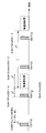
次に、中継装置及び通信装置間における起動処理信号の授受の概要について説明する。図2では、中継装置100、起動対象の通信装置201、その他の通信装置202における動作を時系列に示している。
次に、中継装置及び通信装置間における起動処理信号の授受の概要について説明する。図2では、中継装置100、起動対象の通信装置201、その他の通信装置202における動作を時系列に示している。
中継装置100は、IEEE802.11規格に準拠した通常のビーコンを定期的に発射する。この通常のビーコンは、後述するQUIETエレメントを含んでいない管理フレームである。
ほどなくして、通信装置202が通信装置201に向けたデータフレームを生成し、中継装置100に送信する(ステップS101)。当該データフレームを受信した中継装置100は、通信装置の管理情報によって、通信装置201の動作状態が動作中でないことを認識する。そこで、中継装置100は、起動処理用の報知信号フレーム、起動信号フレームの生成を行う(ステップS102)。
中継装置100は、起動処理開始を報知する報知信号フレームを送信し(ステップS103)、当該報知信号フレームにより設定された無通信区間に合わせて、起動信号フレームを送信する(ステップS104)。
通信装置201を起動させると、中継装置100は、バッファしていた通信装置201宛てのデータフレームを通信装置201に対して転送する(ステップS105)。中継装置100はタイマー管理しているので、起動処理用の報知信号フレーム、起動信号フレームを通信装置201に送信する時刻についてスケジュールを作成することも好適である。スケジュール管理を利用すれば、複数の通信装置を起動処理する際に、優先処理も実現しやすい。
(起動処理用報知信号)
図3は、実施例1に係る中継装置100が送信する起動処理用報知信号として使用するフレームの一例を示す図である。起動処理用報知信号として、二つの報知信号を用いる場合について説明する。ここでは、IEEE802.11で規定されるビーコンを起動処理用の報知信号フレームとして利用する場合を例にとって説明する。ビーコンはIEEE802.11無線LAN規格における管理フレームの一つであり、ヘッダ300とボディ307とフレームチェックシーケンス(FCS)308を備える。ヘッダ300及びにFCS308については、IEEE802.11の仕様に従うものとする。
図3は、実施例1に係る中継装置100が送信する起動処理用報知信号として使用するフレームの一例を示す図である。起動処理用報知信号として、二つの報知信号を用いる場合について説明する。ここでは、IEEE802.11で規定されるビーコンを起動処理用の報知信号フレームとして利用する場合を例にとって説明する。ビーコンはIEEE802.11無線LAN規格における管理フレームの一つであり、ヘッダ300とボディ307とフレームチェックシーケンス(FCS)308を備える。ヘッダ300及びにFCS308については、IEEE802.11の仕様に従うものとする。
ビーコンは、ボディ307にて、当該ビーコンを送信するアクセスポイント(中継装置)がネットワークを運用する際に必要となる情報を伝達する。例えば、Time stamp element310やビーコンの送信間隔を格納するBeacon interval エレメント311、ネットワークの識別情報を格納するSSIDエレメント313等がある。
ネットワークに運用する際に必要となる情報の一つとして、ボディ307にQUIETエレメント314が規定されている。QUIETエレメント314は、通信装置に対して通信を抑制するように指示するものである。
中継装置100では、QUIETエレメント314を含むビーコンを生成して、通信装置に向けて送信する。すると、動作中の通信装置が中継装置100と通信しない状況、すなわち、無通信区間を作り上げる。無通信区間とは、更に詳細には、動作中の通信装置がフレームを一定時間送信しない区間である。この無通信区間中に、起動信号フレームを送信する。起動信号フレームの送信宛の通信装置は、他の通信装置の影響を受けないので、確実な遠隔起動を実現することができる。
QUIETエレメント314は、図3の要素320~要素325に示した6つの要素で構成される。各構成要素の役割はIEEE802.11の仕様に従うが、参考として簡単に説明する。
Element ID320は、QUIETエレメント314を識別するためのIDが格納される要素である。Lenghth321は、(IDとLengthを除く)QUIETエレメント314の長さを格納する要素であり、値6を格納する。Quiet Count322は、次の無通信区間がいくつ先のビーコンインターバルから開始されるかを指定する値を格納する要素である。例えば、“1”を格納した場合には、QUIETエレメント314を含むビーコンの次のビーコンによって始まるビーコンインターバルにおいて、無通信区間が設定される。Quiet period323は、本QUIETエレメント314によって規定される定期的な無通信区間の間に含まれるビーコンインターバルの数を格納する要素である。“0”の時は、定期的な無通信区間は設定されない。Quiet Duration324は、無通信区間の長さを格納する要素である。Quiet Offset325は、Quiet Count322で指定したビーコンを受信してから無通信区間を開始するまでのオフセット値である。
図4は、起動処理用報知信号フレームによって生成される無通信区間の一例を示す図である。ここでは、起動処理用報知信号フレームとして、QUIETエレメント314を含むビーコン401を使用する場合を示している。QUIETエレメント314の要素320~要素325に関する一連の値は、図4に示すような関係になっている。図4の例では、QUIETエレメントを含むビーコン401において、Quiet Count322=1、Quiet Period323=2、Quiet Duration324=β、Quiet Offset325=αと設定している。無通信区間を開始するように指定されたビーコンを受信したので、ビーコン受信からα時間経過した後に無通信区間は開始し、その無通信区間の長さはβである。無通信区間は、2個のビーコンインターバルを繰り返すように、設定されていることがわかる。
ここで、無通信区間の長さβは、起動信号フレームの送信に必要な時間そのものでなく、若干のマージンを加えた時間を設定することが好ましい。例えば、起動対象となる通信装置の通信方式等を考慮して決定するのが好適である。
これまで、遠隔起動処理を開始させる報知信号フレームとそれに基づく処理について述べた。一方、開始だけでなく、遠隔起動処理終了用の報知信号フレームも同様にQUIETエレメントを含むビーコンを用いる形で構成することができる。ただし、Quiet Durationをゼロに設定する。これにより過去に設定された無通信区間が破棄され、通常の状態に戻る。
遠隔起動処理開始用の報知信号フレームだけを用い、終了用フレームを用いない場合には、Quiet Periodをゼロに設定すればよい。これによって、一度だけ無通信区間が設定され、その後は通常の動作に戻る。
以上の説明では、遠隔起動処理に伴う報知信号として、IEEE802.11のQUIETエレメントを含むビーコンを利用する例を説明した。上記したQUIETエレメントの働きをする要素を含む報知信号を利用する通信方法であれば、その他の方法を用いても良い。
(管理情報)
中継装置100がある通信装置から受信したフレームが、新規接続要求や接続情報の更新を要求するフレームである場合、判断部105は接続管理部106に当該フレームを処理するように指示を出す。この指示を受けた接続管理部106は通信方式に合わせた接続処理を行い、記憶部107に当該通信装置の情報を格納する。
中継装置100がある通信装置から受信したフレームが、新規接続要求や接続情報の更新を要求するフレームである場合、判断部105は接続管理部106に当該フレームを処理するように指示を出す。この指示を受けた接続管理部106は通信方式に合わせた接続処理を行い、記憶部107に当該通信装置の情報を格納する。
中継装置100が管理する通信装置の情報としては、“通信装置識別用ID”、“IEEE802.11関連情報”、“通信装置の動作状態”、“通信装置の遠隔起動方法”が好適である。図5は、記憶部107に作られる通信装置の情報のエントリの一例を表にしたものである。
“通信装置識別用ID”は中継装置100が接続するネットワークに接続している各通信装置を識別する識別子である。IDとして、例えばMACアドレスを用いる。“IEEE802.11関連情報”は、同規定によって通信装置を管理する為の情報である。“通信装置の動作状態”は、通信装置の状態である。中継装置100が通信装置と通信ができる場合には「動作中」と示す。通信装置と通信ができない場合としては、外部からの信号で短時間に復帰できる状態である「休止中」、外部からの信号では復帰するが休止中からの復帰よりも長い時間を要する状態である「停止中」がある。中継装置100によって遠隔起動処理が実行されている場合には、「起動処理中」と設定する。通信装置の動作状態は、中継装置100との間での通信成否や、各通信装置から状態変更通知を受けた場合に更新する。ある通信装置からネットワークから離脱する旨を示す情報を受信した場合、中継装置100は当該情報を送信した通信装置のエントリを記憶部107から削除する。
“通信装置の遠隔起動方法”は、通信装置がサポートしている遠隔起動方法の情報である。遠隔起動方法の情報には、遠隔起動に必要な情報も合わせて保存してもよい。さらに、動作状態と遠隔起動方法との対応関係が存在する場合、それらを満たすように複数のエントリを構成しても良い。尚、通信装置が遠隔起動をサポートしていない場合には空欄とする。
例えば、図5のエントリの行511の通信装置は、起動処理中であり、「方法1」で指定された方法で遠隔起動できる通信装置である。行512の通信装置は、休止中であり「方法2」で遠隔起動できる通信装置である。また、行513は動作中であり、遠隔起動をサポートしていない通信装置である。行514と行515の通信装置は、同一通信装置に対するエントリであるが、状態に応じて起動方法が異なる通信装置の格納例である。
通信装置の情報として、“起動信号の送信時間”を管理することもできる。起動処理用の報知信号フレーム、起動信号フレームを通信装置201に送信する時刻についてスケジュールを作成する場合には、必要な管理情報となる。図6は、“起動信号の送信時間”についてもエントリした情報の一例を示す表である。
(動作フロー)
次に、以上のように構成された中継装置100の動作について説明する。以下の説明では、中継装置100の動作として、二つの動作フローを説明する。第1のフローは、ある通信装置からフレームを受信したことを起点とする動作フローである。第1のフローは、例えば、通信装置間の通常のフレーム中継操作に利用するフローである。また、データフレームを受信した場合であって、かつ当該データフレームの送信宛の通信装置が動作中でない場合、起動処理用報知信号フレームを生成と起動信号フレームを生成する。また、当該起動処理用報知信号フレームと起動信号フレームを送信するスケジュールを立てて、送信する。第2のフローは、中継装置100のタイマー管理に関連する動作フローである。第2のフローは、例えば、中継装置100から通信装置に向けて、定期的に報知信号フレームの送信を行う動作フローである。また、前述した第1のフローで決める起動処理用報知信号フレームと起動信号フレームを送信するスケジュールをタイマー管理して、当該タイマー管理のもと起動処理用報知信号フレームと起動信号フレームを送信する。
次に、以上のように構成された中継装置100の動作について説明する。以下の説明では、中継装置100の動作として、二つの動作フローを説明する。第1のフローは、ある通信装置からフレームを受信したことを起点とする動作フローである。第1のフローは、例えば、通信装置間の通常のフレーム中継操作に利用するフローである。また、データフレームを受信した場合であって、かつ当該データフレームの送信宛の通信装置が動作中でない場合、起動処理用報知信号フレームを生成と起動信号フレームを生成する。また、当該起動処理用報知信号フレームと起動信号フレームを送信するスケジュールを立てて、送信する。第2のフローは、中継装置100のタイマー管理に関連する動作フローである。第2のフローは、例えば、中継装置100から通信装置に向けて、定期的に報知信号フレームの送信を行う動作フローである。また、前述した第1のフローで決める起動処理用報知信号フレームと起動信号フレームを送信するスケジュールをタイマー管理して、当該タイマー管理のもと起動処理用報知信号フレームと起動信号フレームを送信する。
まず、図8A~図8Cを用いて第1のフローを説明する、図8A~図8Cは、中継装置100のフレームの受信を起点とする動作の流れを示すフローチャートである。
まず、通信I/F101がフレームを受信すると、受信処理部102にてフレームに対して受信処理を施す(ステップS201)。フレーム記憶部104に、当該受信処理したフレームを保存する(ステップS202)。
次に、判断部105は、当該保存したフレームがデータフレームであるか否かを判断する(ステップS203)。データフレームとは、例えば、IPパケットなどのデータを伝送するフレームであり、接続要求フレームや到達確認フレーム等のコントロールフレームと区別される。尚、制御情報を交換せず、データ交換のみからなるプロトコルにおいては、データフレームであるか否かの判断は、データフレームの内部を解析しなければならない場合がある。例えば、TCP(Transmission Control Protocol)やUDP(User Datagram Protocol)の上で制御情報を交換するプロトコルが使われた場合、それらプロトコルを格納しているフレームを検出する処理が当てはまる。尚、以下の説明においては、上位プロトコルを使って制御情報を交換する例には言及していないが、本実施例は同じように適用可能である。
ステップS203において、フレームがデータフレームと判断した場合(ステップS203-YES)、判断部205は、宛先通信装置の状態を確認する(ステップS204)。判断部205は、当該フレームの受信先として指定された通信装置が動作中であるか否かを判断する(ステップS205)。この判断処理は、記憶部107に保存された情報に基づいて行う。たとえば、図5の動作状態503を見て、通信装置が動作中か否かを判断する。
ステップS205において、判断部205が、フレームの受信先の通信装置が動作中であると判断した場合(ステップS205-YES)、中継装置100は、フレームを受信先の通信装置に転送する。具体的には、まず、判断部105が送信処理部103に送信指示を出す。送信指示を受けると、送信処理部103がフレーム記憶部104から当該フレームを読み出す(ステップS206)。送信処理部103は、読み出したフレームに送信処理を施し(ステップS207)、当該フレームを通信I/F101を介してネットワークへと送信する。
一方、ステップS205において、判断部205が、フレームの受信先の通信装置が動作していないと判断した場合(ステップS205-NO)、判断部205は、フレームの受信先の通信装置に対して、遠隔起動処理を実行中であるか否かを判断する(S208)。遠隔起動処理を実行中であると判断した場合(ステップS208-YES)、中継装置100は処理を終了する。このとき、受信したフレームはすでにフレーム記憶部104に保存されているので、遠隔起動処理完了後に送信する。
一方、遠隔起動処理を実行中でない場合(ステップS208-NO)、判断部105は、対象となる通信装置の情報を記憶部107から読み出し、当該通信装置の記憶部107のエントリを「起動処理中」に変更する(ステップS209)。
「起動処理中」に変更することにより、通信装置は、対象となる通信装置宛に送信されたフレームを受信すると、当該フレーム全てをフレーム記憶部104にバッファする。尚、全てのフレームをバッファする必要は必ずしもなく、実装形態に応じて様々な対応を採ることができる。
フレーム記憶部104は、起動処理中の通信装置宛に送信されたデータフレームは、起動処理中以外の通信装置に送信されたデータフレームと比べてバッファ滞留時間を長くしてもよい。バッファ長を通常より長くしたり、記憶したフレームを通信装置宛に再送する場合、再送を試みるまでの時間を長くしたり、再送を試みる回数を増やす等の処理を行っても良い。これにより、フレームロスを更に防ぐことができる。
尚、バッファ滞留時間を長くすること、フレームの再送を試みるまでの時間を延ばすこと、フレームの再送回数を増やすこと等について、予め閾値を通信装置毎に定めて記憶し、当該閾値に基づいて動作させても良い。通信装置から通知された閾値にしたがって、中継装置100が動作しても良い。通信装置が、閾値を中継装置100に通知する通知手段としては、例えば、通信装置の新規接続要求を行うフレームを用いると良い。
無線中継装置100の接続管理部106は、通信装置から受け取った新規接続要求のフレームに当該閾値が記載されたパラメータを見つけた場合、記憶部107に、当該通信装置と対応付けて保存すればよい。
図10は、中継装置100が記憶部107に記憶して管理する情報として、起動処理に関するパラメータを合わせて保存する一例を示す表である。図10の“起動処理中の対応”という列2000に、バッファ滞留時間、フレームの再送を試みる時間、フレームの再送回数の閾値等、起動処理中の通信装置に対する対応について記憶する。
次に、ステップS209の処理を行った後、中継装置100がフレーム受信先の通信装置を起動する為の処理の説明を行う。判断部105は、フレーム受信先の通信装置に対応するエントリに保存されている情報と共に、起動信号生成部109に起動信号フレームを生成するように指示を出す。起動信号生成部109は起動信号フレームを生成(ステップS210)し、フレーム記憶部104へ保存する。
次に、判断部105は、報知信号生成部108に対して、起動処理用報知信号フレームを生成するように指示を出す。起動信号フレームを安定的に送信するのに適した通信状態を作りだすためである。報知信号生成部108は、起動処理用の報知信号フレームを生成(ステップS211)し、フレーム記憶部104に保存する。尚、通信方式が、起動信号フレームを送信する区間の開始と終了とを異なる起動処理用報知信号で示すことができる通信方式である場合、報知信号生成部108は、起動処理開始用の報知信号と起動処理終了用の報知信号との2つの起動処理用報知信号を生成する。通信方式が、起動信号フレームを送信する区間の終了が自明である通信方式である場合、報知信号生成部108は、起動処理開始用の報知信号だけを生成すれば良い。
次に、判断部105は起動処理用報知信号フレームと起動信号フレームを適切なタイミングで送信するためのスケジュールを立てて(ステップS212、ステップS213)、処理を終了する。例えば、通信方式が、起動処理開始用の報知信号フレームだけを生成すればよい場合は、まず、起動処理開始用報知信号の送信スケジュールを立てて(ステップS212)、次に、起動信号フレームの送信スケジュールをたてる(ステップS213)。
判断部105のスケジュールにもとづき、報知信号フレームと起動信号のフレームの送信が完了すると、記憶部107の当該フレームが送信された通信装置に対応するエントリが更新される。なお、起動処理用報知信号フレームと起動信号フレームは、後述するタイマー管理に基づいて、送信する。
すなわち、図5のエントリのうち動作状態が“起動処理中”から“動作中”に変更される。その結果、フレーム記憶部104にバッファされているフレームのフレーム受信先の通信装置への転送が再開される。また、通信装置の起動処理中に、フレームのバッファ滞留時間を長くする、バッファ長を長くするといった処理を行っていた場合は、通信装置の動作状態に行う通常のフレームのバッファ滞留時間、バッファ長へと戻す。
前述したステップS203において、フレームがデータフレームではなかった場合(ステップS203-NO)、判断部205は、当該フレームが接続要求(または更新要求)か否かを判断する(ステップS214)。接続要求ではなかった場合(ステップS214-NO)、中継装置100は、各制御フレームに対して規定された処理を行い(ステップS220)、処理を終了する。
一方、ステップS214で、受信フレームが接続要求(または更新要求)である場合(ステップS214-YES)、判断部205は、接続要求が新規であるか否かを判断する(ステップS215)。判断部205は、フレームに、新規であるか否かの情報が格納されている場合には、その情報を参照して判断する。フレームに、新規であるか否かの情報が格納されていない場合には、記憶部107に受信フレームの対象となる通信装置の情報が格納されているか否かで判断する。新規接続要求である場合(ステップS215-YES)、記憶部107に対象となる通信装置の情報を格納するためのエントリを作成する(ステップS216)。新規接続要求ではなかった場合(ステップS215-NO)、新たなエントリは作成しない。
次に、中継装置100は、接続要求を送信した通信装置に対する接続処理を行う(ステップS217)。次いで、判断部105は、接続要求に遠隔起動に関する情報が含まれているか否かを判断する(ステップS218)。接続要求に遠隔起動に関する情報が含まれている場合(ステップS218-YES)には、当該遠隔起動に関する情報を用いてエントリを更新する(ステップS219)。一方、遠隔起動に関する情報が含まれていない場合(ステップS218-NO)には、処理を終了する。
次に、中継装置100のタイマー管理に関連する第2の動作フローについて説明する。第2のフローは、例えば、中継装置100から通信装置に向けて、定期的に報知信号フレームの送信を行う動作フローである。また、前述した第1のフローで決める起動処理用報知信号フレームと起動信号フレームを送信するスケジュールをタイマー管理して、当該タイマー管理のもと起動処理用報知信号フレームと起動信号フレームを送信する。
図9A~図9Cは、中継装置100のタイマーに起因する動作の流れを示すフローチャートである。
まず、本動作が開始してから、タイマーがタイムアウトするまで待機する(ステップS301~ステップS302)。判断部105は、タイマーがタイムアウトしたら、タイムアウトしたタイミングが、報知信号フレームを送信するタイミングであるか否かを判断する(ステップS303)。ステップS303で、報知信号フレームを送信するタイミングである場合(ステップS303-YES)、判断部105は、通常用の報知信号フレームを送信するか、起動処理用報知信号フレームを送信するかを判断する(ステップS304)。通常用の報知信号フレームを送信すると判断した場合(ステップS304-YES)、中継装置100は、フレーム記憶部302に事前に作成・保存された報知信号を読み出し、送信処理を施した後ネットワークに送信する(ステップS305~ステップS306)。
次に、中継装置100が生成する起動処理用の報知信号について説明する。起動処理用の報知信号は、起動処理の開始を知らせる報知信号と起動処理の終了を知らせる報知信号の二つを用いる場合と、起動処理の開始を知らせる報知信号のみを用いて、所定の時間が経過した後、中継装置100が通常の動作に戻る場合がある。
起動処理を示す報知信号フレームを送信すると判断した場合(ステップS304-NO)、判断部105は、起動処理の開始を示す報知信号フレームを送信するか起動処理の終了を示す報知信号クレームを送信するか否かを判断する(ステップS307)。判断部105が、起動処理の開始を示す報知信号フレームを送信すると判断した場合(ステップS307-YES)には、中継装置100は、フレーム記憶部104から起動処理開始用報知信号フレームを読み出して送信する(ステップS308~ステップS310)。判断部105が、起動処理の開始終了を示す信号を送信すると判断した場合(ステップS307-NO)には、中継装置100は、フレーム記憶部104から起動処理終了用報知信号フレームを読み出し送信する(ステップS311~ステップS313)。
一方、ステップS303で、判断部105が、報知信号フレームを送信するタイミングではないと判断した場合(ステップS303-NO)、中継装置100は、起動信号フレームをフレーム記憶部104より読み出し、送信する(ステップS314~ステップS315)。その後、判断部100は、起動処理が終了した事を示す報知信号フレームの送信をスケジュールし(ステップS316)、送信した起動信号フレームをフレーム記憶部104から削除する(S317)。次に、当該起動信号フレームの送信先の通信装置の動作状態を「起動処理中」から「動作中」に変更し(ステップS318)、中継装置100は、当該通信装置に向けてバッファしているフレームを送信する(ステップS319)。
尚、バッファしているフレームの送信を再開する処理(ステップS318~ステップS319)の実行は、起動信号フレームを送信した直後である必要は無い。フレームロスが発生しないように、起動信号フレームを送信後、ある程度の時間をおいて実行する方が良い。
以上の動作フローにおいて、ステップS317では、送信が完了した起動信号フレームを記憶部104から削除すると説明したが、削除しなくても良い。
例えば、図7に示すように、記憶部107で管理している通信装置ごとのエントリに“起動信号フレーム”を関連づけて記憶するようにして、今後の送信に備えてもよい。図7の例では、列700として起動信号フレームを保存する欄を設けて保存するようにしている。行701に格納されているID1の通信装置では、F1という起動信号フレームで起動できる事がわかる。また、行702に格納されているID2の通信装置は休止状態にあり、まだ起動信号フレームを生成していないので空欄となっている。
実施例1の中継装置100によれば、無通信区間で起動信号フレームを通信装置に対して送信するため、通信装置に起動信号フレームを確実に伝達することが可能となる。その結果、通信装置を確実に遠隔起動させることができる。
尚、中継装置100は、例えば、汎用のコンピュータ装置を基本ハードウェアとして用いることでも実現することが可能である。すなわち、通信I/F101、受信処理部102、送信処理部103、フレーム記憶部104、判断部105、接続管理部106、記憶部107、報知信号生成部108、起動信号生成部109は、上記のコンピュータ装置に搭載されたプロセッサにプログラムを実行させることにより実現することができる。このとき、中継装置100は、上記のプログラムをコンピュータ装置にあらかじめインストールすることで実現してもよいし、CD-ROMなどの記憶媒体に記憶して、あるいはネットワークを介して上記のプログラムを配布して、このプログラムをコンピュータ装置に適宜インストールすることで実現してもよい。また、フレーム記憶部104、記憶部107は、上記のコンピュータ装置に内蔵あるいは外付けされたメモリ、ハードディスクもしくはCD-R、CD-RW、DVD-RAM、DVD-Rなどの記憶媒体などを適宜利用して実現することができる。
次に、実施例2に係る中継装置1100について説明する。中継装置1100は、実施例1の中継装置100が、通信装置を無通信区間にて起動させることに加えて、起動対象となる通信装置の起動確認を行う。
図11は、実施例2に係る中継装置1100の構成を示すブロック図である。
中継装置1100の構成要素のうち、実施例1に係る中継装置100から変更された構成要素は、判断部1101と起動確認信号生成部1102である。
中継装置1100の構成要素のうち、実施例1に係る中継装置100から変更された構成要素は、判断部1101と起動確認信号生成部1102である。
起動確認信号生成部1102は、判断部1101の指示に基づき、フレーム記憶部104に格納されたフレームに含まれる情報から、通信装置が適切に起動したかどうかを確認をするための起動確認用フレームを生成し、生成した起動確認用フレームをフレーム記憶部104に格納する機能を持つ。
判断部1101は、実施例1の中継装置100の判断部105が持つ機能に加えて次の機能を持つ。第一に、起動確認用フレームを生成するように起動確認信号生成部1102に指示を出し、生成された起動確認用フレームを用いて起動対象の通信装置が起動したか否かを確認する機能である。第二に、起動対象の通信装置が起動した場合、フレーム記憶部104にバッファされたフレームの送信を再開する機能、起動中にフレームのバッファ滞留時間を長くしていたなど通常の状態と異なる状態であった場合は、通常の状態に戻す機能を備える。
次に、以上のように構成した中継装置1100の動作について説明する。図12は、中継装置1100のフレームの受信を起点とする動作の流れを示すフローチャートである。図12のフローチャートでは、図8A~図8Cと同一の動作を行うステップについては説明を省略し、実施例2特有の動作フローについて示している。
図12のフローチャートのうち、図2のフローチャートと異なる点は、報知信号フレームの生成処理(ステップS211)と報知信号フレームの送信をスケジュールする処理(ステップS212)との間に、通信装置の起動を確認するための起動確認信号フレームを生成する処理(ステップS1201)が追加される点である。起動確認信号フレームの種類とその確認方法については後述する。
図13A~図13Cは、中継装置1100のタイマーに起因する動作の流れを示すフローチャートである。図9Aと同一の動作を行うステップについては、説明を省略している。図13A~図13Bのフローチャートでは、起動信号フレームを送信する部分のフローが変更されている。
報知信号フレームを送信するタイミングではなかった場合(ステップS303-NO)、フレームの送信宛の通信装置が「起動処理中」であるかどうかを判断する(ステップS1301)。「起動処理中」である場合(ステップS1301-YES)、起動信号フレームをフレーム記憶部104から読み出して送信する(ステップS314~S315)。次に、記憶部107で管理しているフレームの送信宛の通信装置の動作状態を「起動確認中」に変更し(ステップS1302)、起動確認用フレームの送信をスケジュールする(ステップS1303)。
一方、ステップS1301において、通信装置の動作状態が「起動処理中」ではなかった場合(ステップS1301-NO)、対象通信装置の動作状態は「起動確認中」である。この場合、中継装置1100は、起動確認処理を行う。具体的には、起動確認用フレームをフレーム記憶部104から読み出し(ステップS1304)、ネットワークへ送信する(ステップS1305)。次に、中継装置1100は、対象通信装置からの当該起動確認用フレームに対する対象通信装置からの応答信号を待つため、一定時間待機する(ステップS1306)。次に、応答信号を受信したかどうかを判断する(ステップS1307)。対象通信装置からの起動確認用フレームに対する応答信号があった場合(ステップS1308-YES)、対象通信装置が起動したと判断する。起動処理終了用報知信号の送信をスケジュールするとともに(ステップS316)、起動信号フレームをフレーム記憶部104から削除する(ステップS317)。その後、記憶部107にて管理している当該通信装置の状態を「動作中」に変更し(ステップS318)、フレーム記憶部104にてバッファしているデータフレームの転送を開始する(ステップS319)。
一方、ステップS1308において、対象通信装置からの応答信号が無かった場合(ステップS1307-NO)、起動確認処理の試行回数が規定回数に到達しているかどうかを確認する(ステップS1308)。この規定回数は判断部105が固有値として備えていてもよいし、記憶部107に保存して判断部105が適宜参照するようにしてもよい。ステップS1308において、起動確認処理が規定回数に達している場合(ステップS1308-YES)、引き続き、起動処理の試行回数が規定回数に到達しているかどうかを確認する(ステップS1309)。この規定回数も先の確認処理に関する規定回数と同様に、判断部105が固有値として備えていても良いし、記憶部107に保存して判断部105が適宜参照するようにしてもよい。
起動処理の試行回数が規定回数に達している場合(ステップS1309-YES)、当該通信端末は遠隔起動ができないと判断して、起動処理を取りやめる。具体的には、フレーム記憶部104から起動信号フレームを削除し(ステップS1310)、記憶部107にある当該通信装置のエントリを削除する(ステップS1311)。このとき、判断部1101がIP層の処理を実施できるのであれば、ICMPを用いたエラー応答(例えば、ICMP Host Unreachable)を、フレーム送信元の通信装置に対して送信しても良い。
一方、ステップS1309において、起動処理の試行回数が規定回数に達していない場合(ステップS1309-NO)、再度起動処理を試みる。記憶部107の対象通信装置のエントリに含まれる状態を「起動処理中」に変更し(ステップS1312)、起動信号フレームの送信をスケジュールする(ステップS1313)。
また、ステップS1308において、起動確認処理が規定関数に達していない場合(S1308-NO)、再度起動確認処理を行うため、ステップS1304に戻る。
起動対象となる通信装置が、起動試行の回数、起動確認の試行回数、起動信号フレームを送信してから起動確認を行うまでの時間などの閾値を事前に中継装置1100に通知しておき、中継装置1100はその閾値に従った動作をするようにしても良い。例えば、通信装置は、各閾値を、新規接続要求を行うフレームにより通知する。中継装置1100は、各閾値を受け取ると、接続管理部106が、対応する閾値を記憶部107の対応するエントリに保存する。中継装置が、各閾値を記憶した場合のエントリを図14に示す。
図14は、図5の管理情報に対して、“起動試行回数”、“確認試行回数”、“起動確認までの時間”のエントリが追加されている。例えば、ID1の通信装置を表す行(1406)については全てのパラメータが格納されている。ID2の通信装置を表す行(1407)については、一部のパラメータだけが格納されている。このように通信装置が対応しないパラメータについては空欄にしておけば良い。
次に、実施例2に係る中継装置1100が使用する起動確認フレームとそれを用いた起動確認処理について説明する。
起動確認フレームは、中継装置1100が中継するフレームに含まれる情報に基づいて生成する。フレームに含まれる情報としては、例えば、MACアドレスやIPアドレスを使って生成する。フレームに含まれる情報のうち利用する情報によって通信装置の起動確認の方法が異なる。
フレームに含まれる情報のうちMACアドレスだけを用いた場合には、通信装置について、IEEE802.11などのデータリンク層レベルでの起動確認ができる。MACアドレスだけを使う方法の場合、データリンク層レベルで応答が得られるプロトコルを用いる。例えば、IEEE802.11を用いる。その場合、起動確認フレームとしては、例えばIEEE802.11で規定されたNULLフレームを用いる。NULLフレームは、受信先アドレスを起動確認対象の通信装置のMACアドレスとし、送信元アドレスを中継装置のMACアドレスとする。NULLフレームに対する応答としてACKを受信したことが確認できれば、対象通信装置が起動したと判断する。
フレームに含まれる情報のうち、MACアドレスと更にIPアドレスを用いた場合には、通信装置について、IP層レベルでの起動確認ができる。この場合、起動確認フレームとしては、例えば、ARPパケットやICMP Echo Requestパケット、ICMPv6 Echo Requstパケットなどを用いる。これらを起動確認フレームとして用いた場合、各々のパケットに対して、それぞれARP Reply、ICMP Echo Reply、ICMPv6 Echo Replyを受信したことが確認できれば、対象通信装置が起動したと判断することができる。MACアドレスとIPアドレスを用いて起動確認フレームを生成した場合には、ネットワークインターフェイスは動作しているが、ネットワークインターフェイスより上位層はトラブル等により起動していない場合、そのことを把握でき、より詳細に通信装置の起動状態を確認することができる。特に、通信装置が、遠隔起動のためにデータリンク層の接続を切断しないような動作を行っている場合、IP層での起動確認を行うことが有効である。
例えば、起動確認フレームとして、ARPパケットを生成する場合、パケットのフィールドは、以下のように埋めれば良い。
1)データリンク層レベルのヘッダ
受信先MACアドレス: ブロードキャストアドレス
送信元MACアドレス: 中継装置1100のMACアドレス
2)ARPパケット
送信元MACアドレス: 中継装置1100のMACアドレス
送信元IPアドレス: 中継装置1100のIPアドレス(ただし、中継装置がIPアドレスを持たない場合には、遠隔起動のきっかけとなったフレームに含まれる送信元IPアドレス)
ターゲットMACアドレス: 全てゼロ
ターゲットIPアドレス: 遠隔起動のきっかけとなったフレームに含まれる受信先IPアドレス
また、起動確認フレームとして、ICMP Echo RequestパケットとICMPv6 Echo Requsetパケットを生成する場合、パケットのフィールドは、以下のように埋めれば良い。
受信先MACアドレス: ブロードキャストアドレス
送信元MACアドレス: 中継装置1100のMACアドレス
2)ARPパケット
送信元MACアドレス: 中継装置1100のMACアドレス
送信元IPアドレス: 中継装置1100のIPアドレス(ただし、中継装置がIPアドレスを持たない場合には、遠隔起動のきっかけとなったフレームに含まれる送信元IPアドレス)
ターゲットMACアドレス: 全てゼロ
ターゲットIPアドレス: 遠隔起動のきっかけとなったフレームに含まれる受信先IPアドレス
また、起動確認フレームとして、ICMP Echo RequestパケットとICMPv6 Echo Requsetパケットを生成する場合、パケットのフィールドは、以下のように埋めれば良い。
1)データリンク層レベルのヘッダ
受信先MACアドレス: 遠隔起動のきっかけとなったフレームに含まれる受信先MACアドレス
送信元MACアドレス: 中継装置1100のMACアドレス
2)IPヘッダ/IPv6ヘッダ
送信元IPアドレス/送信元IPv6アドレス: 中継装置1100のIPアドレス/IPv6アドレス(ただし、中継装置1100がIPアドレス/IPv6アドレスを持たない場合、遠隔起動のきっかけとなったフレームに含まれる送信元IPアドレス/IPv6アドレス)
受信先IPアドレス/IPv6アドレス: 遠隔起動のきっかけとなったフレームに含まれる受信先IPアドレス/IPv6アドレス
実施例2の中継装置1100は、無通信区間で起動信号フレームを通信装置に対して送信する。更に、通信装置が起動したか否かを確認する起動確認用フレームを通信装置に対して送信し、通信装置が起動したか否かを確認する。通信装置が起動したことを確認した場合に、データフレームを通信装置に対して送信する。起動確認後、データフレームの送信を行うため、通信装置が起動していないため(たとえば、起動信号フレームが適切に送信できていない場合や、通信装置の起動処理が想定以上の時間を要しているなどの理由により)、通信装置がフレームを正しく受け取れないといったことを防ぐことができる。すなわち、通信装置の起動を確実に確認でき、通信装置へのデータフレームの送信を確実に行うことができる。また、起動確認後、データフレームの送信を行うため、(たとえば、起動処理が想定以上の時間を要していることを想定して)必要以上にデータフレームの送信再開までの時間を長くすることを防ぐことができる。
受信先MACアドレス: 遠隔起動のきっかけとなったフレームに含まれる受信先MACアドレス
送信元MACアドレス: 中継装置1100のMACアドレス
2)IPヘッダ/IPv6ヘッダ
送信元IPアドレス/送信元IPv6アドレス: 中継装置1100のIPアドレス/IPv6アドレス(ただし、中継装置1100がIPアドレス/IPv6アドレスを持たない場合、遠隔起動のきっかけとなったフレームに含まれる送信元IPアドレス/IPv6アドレス)
受信先IPアドレス/IPv6アドレス: 遠隔起動のきっかけとなったフレームに含まれる受信先IPアドレス/IPv6アドレス
実施例2の中継装置1100は、無通信区間で起動信号フレームを通信装置に対して送信する。更に、通信装置が起動したか否かを確認する起動確認用フレームを通信装置に対して送信し、通信装置が起動したか否かを確認する。通信装置が起動したことを確認した場合に、データフレームを通信装置に対して送信する。起動確認後、データフレームの送信を行うため、通信装置が起動していないため(たとえば、起動信号フレームが適切に送信できていない場合や、通信装置の起動処理が想定以上の時間を要しているなどの理由により)、通信装置がフレームを正しく受け取れないといったことを防ぐことができる。すなわち、通信装置の起動を確実に確認でき、通信装置へのデータフレームの送信を確実に行うことができる。また、起動確認後、データフレームの送信を行うため、(たとえば、起動処理が想定以上の時間を要していることを想定して)必要以上にデータフレームの送信再開までの時間を長くすることを防ぐことができる。
次に、本発明の実施例3に係る中継装置1500について説明する。図15は、実施例3に係る中継装置の構成を示すブロック図である。
図1に示した中継装置100の構成とは、判断部1505、記憶部1507、起動信号生成部1509の機能及び動作が異なっている。
記憶部1507は、これまでに保存していた情報に加えて、中継装置1500が中継するフレームのうち優先的に処理するフレームを識別する為の情報を保存する。この情報はフレームを構成する様々な識別子から構築される。例えば、送信元MACアドレス、受信先MACアドレスである。
判断部1505に上位層まで解析する能力を持たせるのであれば、送信元IPアドレスや受信先IPアドレス、トランスポートプロトコル、TCPもしくはUDPの送信元ポート番号、受信先ポート番号なども使用できる。優先度に関する情報は、通信装置の接続情報と独立に保存しておいても良いし、統合した形で保存しておいても良い。
図16は、独立して優先度情報を記憶部1507で保存する場合の一例を示している。図16に示す例では、3つの通信に対する通信識別情報と優先度情報が格納されている。これらの通信は、先に述べた各識別子によって識別されている。行1611の通信と行1613の通信は対応する一つの通信であり、方向が異なっている。
図17は、通信装置の接続管理情報と併せて優先度情報を記憶部で保存する場合の一例を示している。図17の例では、3つの通信装置に対する接続管理情報(列1701~列1704)と、各通信装置に対応する優先度情報(列1705)が格納されている。優先度情報は「高」「中」「低」のように設定しているが、その粒度については限定しない。通信方式によって実現可能な優先制御の粒度を利用すればよい。中継装置1500が粒度や優先制御の方法が異なる二つのネットワークを接続する場合、中継装置1500の判断部1505が適切に変換する。
判断部1505は、これまでの機能に加えて、記憶部1507に保存されている優先すべき通信の条件を用いて、受信したデータフレームを優先的に送信するかどうかを判断する機能を具備する。判断結果に基づいて、起動信号生成部1509や報知信号生成部108に対して出す指示の内容を変更する。
優先処理すべき(優先度が高い)と判断したデータフレームにおいて、受信先の通信装置を遠隔起動する必要が発生した場合には、後述するNAV(Network Allocation Vector)を使った起動信号を生成し、送信するように指示を出す。そうでない場合には、これまでに述べた起動処理用報知信号フレームによる無通信区間を設定した上で起動信号フレームを送信するように指示を出す。
起動信号生成部1509は、これまでに述べた起動信号フレームに加え、起動信号フレームの伝播に必要な時間を考慮したNAVを設定する信号と、そのNAVを更新しながら起動信号フレームの役割も果たす信号フレーム(請求項4で第2の起動信号フレームに対応)とを生成する機能を具備する。ここで、NAVは、ネットワークに接続する通信装置に対して一定期間フレームを送信しないように指示する無通信区間を設定するフレームである。
図18は、NAV化された起動信号フレームの一例を時系列で模式した図である。図18(a)は、複数の信号の集合を起動信号フレームとみなす例であり、図18(b)は、単一の信号で起動信号フレームを作る例である。
いずれの場合も、起動信号フレーム全体をカバーする形でNAVが設定される。両方式において、起動信号フレームを送信する前に、起動信号フレームの長さに合わせたNAVを設定することを目的としたフレーム(例えば、フレーム1806とフレーム1807が相当する)を別途送信しても良い。
また、起動信号フレームの送信にNAVを設定できる時間よりも長い時間を要する場合、上段のように複数のフレームに分けて、複数のNAVを設定する形で起動信号フレームを生成しても良い。
実施例3において、優先度の高い通信がなされている状態で、優先度が低い通信をきっかけとする起動信号を送信する場合を考える。図19は、高優先度通信信号が送信される場合において、無通信区間が設定される様子を示す模式図である。
図19のフレーム1906は、休止中の通信装置に向かう低優先度のフレームであり、一連の遠隔起動のきっかけとなるフレームである。フレーム1900と1901は、起動開始用報知信号である。フレーム1902は起動終了用報知信号であり、フレーム1903は高優先度通信に対応するフレームである。区間1904はフレーム1900の起動開始用報知信号によって生成される無通信区間である。フレーム1905は、無通信区間1904で送信された低優先度通信に対応する起動信号フレームである。また、フレーム1907は休止中の通信装置に向かう高い優先度の通信に対応するフレームである。フレーム1908は、高い優先度の通信を行う通信装置を起動させるための起動信号フレームである。
このような構成に係る中継装置1500の動作フローを図20A~Cに示す。図20A~Cは、実施例3に係る中継装置1500におけるフレームの受信を起点とする動作の流れを示すフローチャートである。
図20A~Cに示すように、フレームを転送する際に優先度に基づくスケジューリングを行う処理(ステップS2001)と、起動信号の生成ならびに送信処理(ステップS2002~ステップS2009)が変更されている。優先度が高いフレームの受信をきっかけとした起動信号の生成から送信までの処理は、連続的に実行されるようになっている。
動作中ではない通信装置に向かうフレームを受信し、その通信装置が起動処理中ではない場合(ステップS205-NO、ステップS208-NO)、記憶部1507に保存されている当該通信装置に対するエントリの状態を「起動処理中」に変更する(ステップS209)。その後、受信したフレームが優先的に処理すべきものか、通常通り対応するものかを確認する(ステップS2002)。
受信したフレームが通常通り処理すべきフレームだった場合(ステップS2002-YES)、図8Bと同じように処理をする。例えば、図16の行1612に該当するフレームを受信したことによって一連の動作フローが実行されていたと仮定する。この場合、行1612は優先度が低い通信に分類されている為、図8Bと同じように報知信号による無通信区間を設定した上での遠隔起動処理を行う。
ただし、本実施形態における報知信号生成部1508は、単純に図8Bと同じ動作をするだけではなく、起動処理開始用の報知信号によって生成される無通信区間が、他の優先的な通信を妨害しないように適切な位置に配置するようにスケジュールしても良い。これを実現するためは、記憶部1507に優先的な通信に対する時間的な情報(例えば、通信速度、許容する最大遅延、フレーム間隔など)の情報を保存しておき、判断部1505がそれを参照して判断を行った上、報知信号生成部1508に指示する際に適切な値を指定すればよい。ここで、フレーム間隔とは、高優先度通信の信号の送信間隔である。図では、高優先度通信の信号1903の信号の送信間隔である。また、最大遅延とは、所定のフレーム間隔1903より長い間隔を空けて、信号1903を送信する場合のフレーム間隔からの最大延長期間である。尚、記憶部1507に保存する時間的な情報は、図16や図17の優先度情報と共に保存すればよい。事前に把握している高優先度の通信を避ける形で遠隔起動信号を送信することができるため、高い優先度の通信に対する影響を抑えながら、より安定した形での遠隔起動が実現できる。例えば、図19においては、報知信号により設定される無通信区間1904を、高優先度の信号1903を送信する区間以外の区間に設定している。例えば、報知信号生成部1508は、時間的な情報としてフレーム間隔を用いて、無通信区間1904を設定する。図19に示すように、中継装置1500が、高優先度の信号1903を一定の間隔で送信している場合、当該間隔を記憶部1507に記憶している。報知信号生成部1508は、記憶部1507に記憶された当該間隔を参照して、高優先度の信号1903と衝突しない部分に、無通信区間1904を設定する。また、報知信号生成部1508は、時間的な情報としてフレーム間隔と許容する最大遅延を用いて、報知信号により設定される無通信区間1904を設定する。報知信号生成部1508は、フレーム間隔と最大遅延との和の区間に、無通信区間1904を設定する。
一方、優先的に処理すべきフレームだった場合(ステップS2002-NO)、先のNAVを伴った起動信号を生成・送信する処理を行う。また、起動信号自身にも同様の優先度を与える。例えば、図16の行1611や行1613に該当するフレームを受信した事によって一連の動作フローが実行されていたと仮定する。この場合、高い優先度に分類されているのでNAVを伴う起動信号を使う方式を選択すると共に、生成した起動信号にも高い優先度を与える。
はじめにNAVを伴った起動信号を生成し、フレーム記憶部104に保存する(ステップS2003)。判断部1505は、他のフレームと同じように(ただし、本処理のきっかけとなったフレームと同じ優先度で)起動信号フレームを送信するように、送信処理部103に指示する。送信処理部103は当該起動信号フレームを読み出し(ステップS2004)、優先度を考慮した適切なタイミングでネットワークへと送信する(ステップS2005)。その後、フレーム記憶部104から起動信号フレームを削除する(ステップS2006)。
起動信号フレームの送信が終わると、記憶部107で管理している当該通信装置の状態を「動作中」に変更する(ステップS2007)。その後、フレームロスが発生しないようにある程度の時間を置いてから、フレーム記憶部104にバッファしておいたフレームの送信を開始する(ステップS2008)。
図19の例では、フレーム1907が休止中の通信装置に向かう高い優先度の通信であり、フレーム1908が対応する起動信号フレームである。NAVを使用することで、報知信号による無通信区間を設定されるまで待機する必要が無いため、高速に起動信号を送信できる。
一連の動作において、受信したフレームがこのような優先度情報の管理データに該当しない場合には、優先度情報が設定されていないものとして扱えば良い。
本実施例3において追加された起動信号の生成・送信方法は、実施例1の形態に比べて高速に起動信号フレームを送信できるという利点がある。
尚、無線通信におけるQoSの確保方法については、中継装置1500が接続するネットワークの方式に従う。例えばIEEE802.11を使用した無線LANであれば、送信間隔やバックオフ時間を変更するなどによって実現できる。すなわち、優先度が高い通信ほど短い送信間隔やバックオフ時間で送信権を得るようにすれば良い。
また、実施例1のおけるタイマーをきっかけとする動作(図9A~図9C)については、中継装置1500でも同じように具備している。
以上、本実例の中継装置1400によれば、受信したフレームを優先的に処理する場合に、NAVを用いて起動させることにより、高速にかつ確実に通信装置に対して起動信号を送信することが可能となる。また、優先度の低いフレームについて無通信区間を設定する場合に、優先度の高いフレームの通信を妨害しないような期間を設定するため、優先度の高いフレームの送信先の通信装置に対して、優先度の高いフレームを迅速に通信装置に送信することができる。その結果、システム全体としての優先制御ポリシーを守ることができる。
実施例4にかかる通信装置は、実施例1から3の中継装置の技術を、ネットワークを管理する機能を持たない通信装置に適用する例である。
実施例1~3の中継装置(例えば、IEEE802.11のイン不ラストラクチャモードにおけるアクセスポイント)は、ネットワークを管理する機能を持つ装置であった。それに対して、実施例4の通信装置は、ネットワークを管理する機能を持たない。例えば、実施例4の通信装置は、たとえば、アドホックネットワークを構成する通信装置である。実施例4に係る通信装置は、アドホックネットワークモードに対応した通信装置であって、実施例1から3の中継装置の構成及び動作をそのまま適用することができる。
実施例4の通信装置の動作について説明する。図21は、7つの通信装置(2101~2107)を含むアドホックネットワークである。各通信装置の電波の到達範囲は点線で図示した部分(2111~2117)であるとする。通信装置は、アドホックルーティングプロトコルを用いて各通信装置への最適な経路を把握しているものとする。
以下では、通信装置A2101が通信装置F2106にパケット(データフレーム)を送信する場合を説明する。通信装置A2101から通信装置F2106へパケットを送るための経路は(A→E→D→F)と(A→D→F)の二つがある。実施例4では、(A→D→F)の経路を経由する場合を説明する。
まず、アドホックネットワークにおいて、通信装置D2104と通信装置F2106がともに動作中である場合を説明する。通信装置Aが、通信装置F2106を宛先アドレスとするパケットを生成し、通信装置D2104に送信する。通信装置D2104は、受信したパケットが自装置に隣接する通信装置F2106宛であることを判断すると、パケットを通信装置F2106に転送する。このようにしてパケットは所望の通信装置に到達する。
次に、通信装置F2106が停止している場合を説明する。この場合、 通信装置F2106に隣接する通信装置D2104が通信装置F2106に対して起動信号を送信することで、通信装置F2106を起動させ、ネットワークに復帰させる必要がある。通信装置D2104は、実施例1の中継装置100と同様の動作を行う。
具体的な通信装置D2104の動作と構成を説明する。通信装置D2104は、近隣する通信装置の動作状態を継続的に管理している。例えば、図5に示した情報を管理する。なお、図5はインフラストラクチャモードにおけるアクセスポイントが管理する情報であるが、アドホックモードの場合にも同様の情報を各通信装置が保持することとなる。
通信装置A2101からパケットを受信し、起動信号を送信するまでの動作は、図2に示した動作と同様の動作である。図2において、中継装置100を通信装置D2104、その他の通信装置202を通信装置A2101、起動対象の通信装置201を通信装置F2106と読み替えればよい。したがって、通信装置D2104の内部動作は、実施例1における中継装置100と同様の動作を行う。すなわち、通信装置D2104は、通信装置A2101からパケットを受信すると、起動処理開始を報知する報知信号を送信する。そして、報知信号により設定した無通信区間において、起動信号を通信装置F2106に送信する。通信装置F2106起動後、通信装置D2104は、通信装置F2106に対してパケットを送信する。
なお、通信装置D2104に対して、実施例2の中継装置1100の構成、動作も適用することができる。すなわち、通信装置D2104は、通信装置F2106に対して、起動信号を生成後、起動確認用フレームを送信することにより、通信装置F2106の起動を確認することができる。そして、起動を確認した後にパケットの転送を行うことができる。
また、通信装置D2104に対して、実施例3の中継装置1500の構成、動作も適用することができる。すなわち、通信装置D2104は、通信装置A2101から受信したパケットに付されていた優先度に基づき、通信装置F2106の起動を行う。
以上の説明では、パケットの宛先となる通信装置が停止している場合の通信装置の起動を例にとって説明したが、経路上の通信装置が停止している場合にも同様に適用することができる。
実施例4によれば、アドホックネットワークにおいて、隣接する通信装置が、動作状態にない通信装置を、無通信区間を設定した上で起動させるため、通信装置を確実に起動させることができる。通信装置を起動させることにより、当該通信装置に対して、データフレームを確実に伝達することができる。
実施例5の中継装置2200は、起動信号以外の通信を通信インターフェイス101が行い、起動信号の送信を起動専用通信インターフェイス2201が行う中継装置である。
実施例1~3の中継装置では、起動信号以外の通信と起動信号の送信を1つの通信インターフェイスが行う例を説明した。図22に示すように、実施例5の中継装置2200は、起動信号以外の通信を通信インターフェイス101が行い、起動信号の送信を起動専用通信インターフェイス2201が行う。たとえば、通信インターフェイス101はIEEE802.11を使用する。また、起動専用通信インターフェイス2201はIEEE802.11と同じ周波数帯もしくは重なる周波数帯を使用し、起動信号に特化した電波を送信することとする。
本実施例の中継装置2200によれば、起動専用通信インターフェイス2201を介して送信する起動信号を送信するときに、通信インターフェイス101の無線フレームの送受信を停止できる。その結果、起動信号送信時の無線フレームによる干渉を防ぎ、遠隔起動をより確実に達成できる。
本実施例の中継装置2200の動作で異なる点について以下説明する。中継装置2200は、起動信号を、起動専用通信I/F2201が送信する。また、中継装置2200は、図8BのステップS210にて生成した起動信号フレームをフレーム記憶部104に保存せずに、起動信号生成部109に保存する。また、図9CのステップS314において起動信号フレームをフレーム記憶部104から読み出ださずに、起動信号生成部109内部の処理になる。そのほかの中継装置2200の動作は、実施例1の中継装置100と同様である。
実施例5の中継装置によれば、無通信区間で起動信号フレームを通信装置に対して送信するため、通信装置に起動信号フレームを確実に伝達することが可能となる。その結果、通信装置を確実に遠隔起動させることができる。また、実施例5の中継装置によれば、起動信号送信用、データ通信用のインターフェイスを別々に設けることで、起動信号送信時にデータ通信を停止させることができる。その結果、データ通信の影響を受けることなく起動信号フレームを通信装置に対して送信できる。その結果、より確実に通信装置を起動させることが可能となる。
尚、本発明は上記実施例そのままに限定されるものではなく、実施段階ではその要旨を逸脱しない範囲で構成要素を変形して具体化できる。また、上記実施例に開示されている複数の構成要素の適宜な組み合わせにより、種々の発明を形成できる。例えば、実施例に示される全構成要素から幾つかの構成要素を削除してもよい。さらに、異なる実施例にわたる構成要素を適宜組み合わせてもよい。
100、1100、1500、2200・・・中継装置、101・・・通信I/F、102・・・受信処理部、103・・・送信処理部、104・・・フレーム記憶部、105、1101、1505・・・判断部、106・・・接続管理部、107、1507・・・記憶部、108・・・報知信号生成部、109、1509・・・起動信号生成部、1102・・・起動確認信号生成部、2201・・・起動専用通信インターフェイス、2101・・・通信装置A、2102・・・通信装置B、2103・・・通信装置C、2104・・・通信装置D、2105・・・通信装置E、2106・・・通信装置F、2107・・・通信装置G
Claims (6)
- 管理するネットワークに接続し、データフレームを受信し、起動信号フレームを送信し、報知信号フレームを送信するインターフェイスと、
前記ネットワークに接続する第1の通信装置に送信するデータフレームを受信した場合であって、かつ前記第1の通信装置が動作中でない場合に、前記第1の通信装置を起動させる起動信号フレームを生成する起動信号生成部と、
前記ネットワークに接続する通信装置に対して一定時間フレームの送信をしない無通信区間を設定する報知信号フレームを生成する報知信号生成部とを備え、
前記インターフェイスを介して、前記ネットワークに接続する通信装置に前記報知信号フレームを送信し、前記無通信区間を設定した状態で、前記第1の通信装置に前記起動信号フレームを送信することを特徴とする中継装置。 - 前記データフレーム、前記起動信号フレーム、前記報知信号フレームを格納するフレーム記憶部を更に備え、
前記フレーム記憶部は、前記起動信号フレームにより起動中である第1の通信装置に送信するデータフレームを前記ネットワークに接続された通信装置であって起動中でない通信装置に送信するデータフレームと比べて長い時間記憶することを特徴とする請求項1記載の中継装置。 - 前記第1の通信装置が起動したかどうかを確認する確認フレームを生成する確認信号生成部をさらに備え、
前記インターフェイスを介して、前記第1の通信装置に前記起動信号フレームを送信後、前記確認フレームを送信し、前記確認フレームに対する応答信号を受信すると、前記第1の通信装置にデータフレームを送信することを特徴とする請求項2記載の中継装置。 - 前記ネットワークに接続する通信装置に送信するデータフレームを受信した場合に、当該通信装置毎のデータフレームを送信する優先度を判断する判断部を備え、
前記第1の通信装置にデータフレームを送信する優先度が高いと判断した場合、前記起動信号生成部は、前記起動信号フレームと前記ネットワークに接続する通信装置に対して一定時間フレームを送信しない無通信区間を設定する報知信号フレームとを含む第2の起動信号フレームを生成し、
前記インターフェイスを介して、前記第2の起動信号フレームを送信することを特徴とする請求項3記載の中継装置。 - 前記ネットワークに接続する通信装置に送信するデータフレームのうち前記優先度が高いデータフレームを送信する送信間隔を含む時間情報を記憶する記憶部を更に備え、
前記判断部が前記第1の通信装置に送信するデータフレームの優先度が低いと判断した場合、前記報知信号生成部は、前記時間情報に基づき、前記ネットワークに接続する通信装置に送信するデータフレームのうち優先度が高いデータフレームを送信する区間以外に無通信区間を設定する報知信号フレームを生成することを特徴とする請求項4記載の中継装置。 - 更に、前記起動信号フレームを送信する第2のインターフェイスを備えることを特徴とする請求項5記載の中継装置。
Priority Applications (3)
| Application Number | Priority Date | Filing Date | Title |
|---|---|---|---|
| PCT/JP2010/001025 WO2011101901A1 (ja) | 2010-02-18 | 2010-02-18 | 中継装置 |
| JP2012500384A JP5563058B2 (ja) | 2010-02-18 | 2010-02-18 | 中継装置、通信方法 |
| US13/419,803 US8908589B2 (en) | 2010-02-18 | 2012-03-14 | Repeater device |
Applications Claiming Priority (1)
| Application Number | Priority Date | Filing Date | Title |
|---|---|---|---|
| PCT/JP2010/001025 WO2011101901A1 (ja) | 2010-02-18 | 2010-02-18 | 中継装置 |
Related Child Applications (1)
| Application Number | Title | Priority Date | Filing Date |
|---|---|---|---|
| US13/419,803 Continuation US8908589B2 (en) | 2010-02-18 | 2012-03-14 | Repeater device |
Publications (1)
| Publication Number | Publication Date |
|---|---|
| WO2011101901A1 true WO2011101901A1 (ja) | 2011-08-25 |
Family
ID=44482527
Family Applications (1)
| Application Number | Title | Priority Date | Filing Date |
|---|---|---|---|
| PCT/JP2010/001025 Ceased WO2011101901A1 (ja) | 2010-02-18 | 2010-02-18 | 中継装置 |
Country Status (3)
| Country | Link |
|---|---|
| US (1) | US8908589B2 (ja) |
| JP (1) | JP5563058B2 (ja) |
| WO (1) | WO2011101901A1 (ja) |
Cited By (3)
| Publication number | Priority date | Publication date | Assignee | Title |
|---|---|---|---|---|
| JP2013192078A (ja) * | 2012-03-14 | 2013-09-26 | Yamaha Corp | 通信制御装置 |
| JP2016111639A (ja) * | 2014-12-10 | 2016-06-20 | サイレックス・テクノロジー株式会社 | 無線通信機器、無線アクセスポイント、及び、無線通信システム |
| JP2018148579A (ja) * | 2018-05-25 | 2018-09-20 | 学校法人 関西大学 | 無線装置、それを備えた無線通信システムおよび無線装置において実行されるプログラム |
Families Citing this family (2)
| Publication number | Priority date | Publication date | Assignee | Title |
|---|---|---|---|---|
| US9167470B2 (en) * | 2010-08-05 | 2015-10-20 | Htc Corporation | Handling signaling congestion and related communication device |
| WO2013149383A1 (en) * | 2012-04-05 | 2013-10-10 | Nokia Corporation | Method, apparatus, and computer program product for adaptive relaying data distribution in wireless networks |
Citations (2)
| Publication number | Priority date | Publication date | Assignee | Title |
|---|---|---|---|---|
| JP2007081519A (ja) * | 2005-09-12 | 2007-03-29 | Hitachi Ltd | 無線lanシステム |
| JP2007243238A (ja) * | 2006-03-03 | 2007-09-20 | Matsushita Electric Ind Co Ltd | 中継装置、通信端末、及び通信システム |
Family Cites Families (2)
| Publication number | Priority date | Publication date | Assignee | Title |
|---|---|---|---|---|
| JP4095501B2 (ja) | 2003-06-25 | 2008-06-04 | インターナショナル・ビジネス・マシーンズ・コーポレーション | コンピュータ装置、無線アクセスポイント、無線ネットワークを介した電源投入方法、フレーム聴取方法、フレーム送信方法、およびプログラム |
| US20070206500A1 (en) * | 2006-03-02 | 2007-09-06 | Motorola, Inc. | Method and apparatus for beacon transmission within a multi hop communication system |
-
2010
- 2010-02-18 JP JP2012500384A patent/JP5563058B2/ja not_active Expired - Fee Related
- 2010-02-18 WO PCT/JP2010/001025 patent/WO2011101901A1/ja not_active Ceased
-
2012
- 2012-03-14 US US13/419,803 patent/US8908589B2/en not_active Expired - Fee Related
Patent Citations (2)
| Publication number | Priority date | Publication date | Assignee | Title |
|---|---|---|---|---|
| JP2007081519A (ja) * | 2005-09-12 | 2007-03-29 | Hitachi Ltd | 無線lanシステム |
| JP2007243238A (ja) * | 2006-03-03 | 2007-09-20 | Matsushita Electric Ind Co Ltd | 中継装置、通信端末、及び通信システム |
Cited By (3)
| Publication number | Priority date | Publication date | Assignee | Title |
|---|---|---|---|---|
| JP2013192078A (ja) * | 2012-03-14 | 2013-09-26 | Yamaha Corp | 通信制御装置 |
| JP2016111639A (ja) * | 2014-12-10 | 2016-06-20 | サイレックス・テクノロジー株式会社 | 無線通信機器、無線アクセスポイント、及び、無線通信システム |
| JP2018148579A (ja) * | 2018-05-25 | 2018-09-20 | 学校法人 関西大学 | 無線装置、それを備えた無線通信システムおよび無線装置において実行されるプログラム |
Also Published As
| Publication number | Publication date |
|---|---|
| JPWO2011101901A1 (ja) | 2013-06-17 |
| JP5563058B2 (ja) | 2014-07-30 |
| US20120230246A1 (en) | 2012-09-13 |
| US8908589B2 (en) | 2014-12-09 |
Similar Documents
| Publication | Publication Date | Title |
|---|---|---|
| KR102630472B1 (ko) | 통합된 액세스 및 백홀 베어러 관리를 위한 방법, 장치 및 시스템 | |
| JP6662477B2 (ja) | 最適化されたue中継 | |
| JP5986244B2 (ja) | チャネルアグリゲーションおよび媒体アクセス制御再送信を実行するための方法および装置 | |
| CN110461021B (zh) | 一种调度请求取消方法及设备 | |
| JP6240273B2 (ja) | メッシュネットワークにおけるdhcpサービスを使用する認証 | |
| JP2017200185A (ja) | データボリューム情報を送信する方法及びユーザ機器 | |
| JP2018506203A (ja) | 日和見的なデュアルバンド中継 | |
| WO2013134668A2 (en) | Systems and methods for establishing a connection setup through relays | |
| JP5033852B2 (ja) | 検針データ収集システム | |
| WO2017004353A1 (en) | Distributed reactive resource and schedule management in time slotted channel hopping networks | |
| JP2018514975A (ja) | IoEデバイスの間での関連付け要求シグナリングのための機構 | |
| WO2013166670A1 (zh) | 上行信道资源配置方法和设备 | |
| JP5563058B2 (ja) | 中継装置、通信方法 | |
| KR20120091314A (ko) | 배터리 없는 지그비 디바이스를 포함한 네트워크에서 통신하기 위한 방법, 그것을 위한 네트워크 및 디바이스 | |
| CN118435657A (zh) | 用于共享频谱上的nr侧链路资源分配的方法和系统 | |
| CN112040565B (zh) | 移动通信系统、方法及装置 | |
| JP4747646B2 (ja) | 無線通信システム,無線通信装置,無線通信方法,およびコンピュータプログラム。 | |
| CN108391297A (zh) | 设备切换方法及设备、承载配置方法及设备、通信系统 | |
| CN111510929B (zh) | Iab网络中进行lcid扩展的方法及装置 | |
| CN117693997A (zh) | 逻辑信道优先级排序方法、装置、设备及存储介质 | |
| JP6415949B2 (ja) | 無線通信装置 | |
| JP5137806B2 (ja) | 通信制御方法および通信装置 | |
| JP2015053581A (ja) | 送信装置、受信装置、管理装置及びプログラム | |
| JP2010206551A (ja) | マルチホップ無線通信システム、及び方法 | |
| KR101289469B1 (ko) | 이동 통신 시스템에서 ip 관리 메시지를 위한 연결 설정방법 및 그 장치 |
Legal Events
| Date | Code | Title | Description |
|---|---|---|---|
| WWE | Wipo information: entry into national phase |
Ref document number: 2012500384 Country of ref document: JP |
|
| 121 | Ep: the epo has been informed by wipo that ep was designated in this application |
Ref document number: 10846044 Country of ref document: EP Kind code of ref document: A1 |
|
| NENP | Non-entry into the national phase |
Ref country code: DE |
|
| 122 | Ep: pct application non-entry in european phase |
Ref document number: 10846044 Country of ref document: EP Kind code of ref document: A1 |