WO2011099211A1 - 立体画像印刷物、立体画像印刷表示装置、及び立体画像印刷物における網点画像印刷物の印刷方法 - Google Patents
立体画像印刷物、立体画像印刷表示装置、及び立体画像印刷物における網点画像印刷物の印刷方法 Download PDFInfo
- Publication number
- WO2011099211A1 WO2011099211A1 PCT/JP2010/070934 JP2010070934W WO2011099211A1 WO 2011099211 A1 WO2011099211 A1 WO 2011099211A1 JP 2010070934 W JP2010070934 W JP 2010070934W WO 2011099211 A1 WO2011099211 A1 WO 2011099211A1
- Authority
- WO
- WIPO (PCT)
- Prior art keywords
- halftone
- printed
- printed matter
- image printed
- pixels
- Prior art date
- Legal status (The legal status is an assumption and is not a legal conclusion. Google has not performed a legal analysis and makes no representation as to the accuracy of the status listed.)
- Ceased
Links
Images






Classifications
-
- G—PHYSICS
- G03—PHOTOGRAPHY; CINEMATOGRAPHY; ANALOGOUS TECHNIQUES USING WAVES OTHER THAN OPTICAL WAVES; ELECTROGRAPHY; HOLOGRAPHY
- G03B—APPARATUS OR ARRANGEMENTS FOR TAKING PHOTOGRAPHS OR FOR PROJECTING OR VIEWING THEM; APPARATUS OR ARRANGEMENTS EMPLOYING ANALOGOUS TECHNIQUES USING WAVES OTHER THAN OPTICAL WAVES; ACCESSORIES THEREFOR
- G03B35/00—Stereoscopic photography
- G03B35/18—Stereoscopic photography by simultaneous viewing
- G03B35/24—Stereoscopic photography by simultaneous viewing using apertured or refractive resolving means on screens or between screen and eye
-
- G—PHYSICS
- G02—OPTICS
- G02B—OPTICAL ELEMENTS, SYSTEMS OR APPARATUS
- G02B30/00—Optical systems or apparatus for producing three-dimensional [3D] effects, e.g. stereoscopic images
- G02B30/20—Optical systems or apparatus for producing three-dimensional [3D] effects, e.g. stereoscopic images by providing first and second parallax images to an observer's left and right eyes
- G02B30/26—Optical systems or apparatus for producing three-dimensional [3D] effects, e.g. stereoscopic images by providing first and second parallax images to an observer's left and right eyes of the autostereoscopic type
- G02B30/27—Optical systems or apparatus for producing three-dimensional [3D] effects, e.g. stereoscopic images by providing first and second parallax images to an observer's left and right eyes of the autostereoscopic type involving lenticular arrays
-
- G—PHYSICS
- G02—OPTICS
- G02B—OPTICAL ELEMENTS, SYSTEMS OR APPARATUS
- G02B3/00—Simple or compound lenses
- G02B3/0006—Arrays
- G02B3/0037—Arrays characterized by the distribution or form of lenses
- G02B3/005—Arrays characterized by the distribution or form of lenses arranged along a single direction only, e.g. lenticular sheets
Definitions
- the present invention relates to a stereoscopic image printing display device including a stereoscopic image printed material using a lenticular lens, and more particularly to a halftone dot printing technique of a halftone image printed material which is arranged on the back surface of a lenticular lens and relates to density gradation expression.
- an FM (frequency modulation) screen method and an AM (amplitude modulation) screen method are known (for example, Patent Document 1).
- the FM screen method is a method of expressing density gradation by the density of halftone dots having a certain size
- the AM screen method is a method of expressing density gradation by the size of halftone dots.
- halftone dot printing of a slender image a method of printing halftone dots with an AM screen in the longitudinal direction around the center in the minimum unit area for gradation expression, or an FM screen so that the halftone dots are individually separated.
- a method for halftone printing is proposed (Patent Document 2).
- the applicant assigns a halftone angle for each color plate such as the C plate, the M plate, the Y plate, and the K plate in order to suppress the occurrence of moire (interference fringes). It has been proposed to print halftone dots so that adjacent halftone dots touch each other in a slender image.
- the applicant of the present application discloses a plurality of slender images of a halftone dot printed matter for each color plate in a minimum unit area for gradation expression in order to reduce image roughness. Has been proposed to perform halftone dot printing with an amplitude modulation screen in the longitudinal direction around the reference position.
- the present invention provides a three-dimensional image printed matter that further improves the color mixture, reduces the occurrence of moire, improves the fineness of appearance, and reduces the roughness of the image, and a three-dimensional image using the same.
- An object is to provide a print display device.
- the stereoscopic image print according to the present invention includes a lenticular lens in which a plurality of semi-cylindrical lenses are continuously arranged, and a back surface of the lenticular lens, and a plurality of elongated images corresponding to each semi-cylindrical lens.
- a halftone dot image printed matter that is continuously arranged and printed with halftone dots, and the halftone dot image printed matter is formed by arranging a plurality of minimum unit areas for gradation expression for each color plate. And the number of reference points of the unit area in at least some of the color plates having pixels that are preferentially assigned as reference points of the pixels to be halftone printed in the unit area.
- this stereoscopic image printed matter it is possible to improve the color mixture, reduce the occurrence of moire, improve the fineness of the appearance, and reduce the feeling of roughness of the image.
- the reference image is continuously extended from the reference point in both the longitudinal directions of the elongated image based on the gradation expression.
- Each pixel may be configured to be printed. With this configuration, it is possible to further improve the color mixture, reduce the occurrence of moire, improve the fineness of appearance, and reduce the feeling of roughness of the image.
- a stereoscopic image printing display device includes the stereoscopic image printed matter and a backlight device for irradiating the halftone image printed matter in the stereoscopic image printed matter from the back side.
- the halftone image printed material can be observed in a bright state by illumination of the backlight device.
- the printing method of the halftone dot image printed matter in the three-dimensional image printed matter according to the present invention includes a lenticular lens in which a plurality of semicylindrical lenses are continuously arranged, and a rear surface of the lenticular lens.
- a printing method of halftone image printed matter in a three-dimensional image printed matter comprising a plurality of elongated images corresponding to a lens continuously arranged and halftone dot printed matter, wherein a plurality of elongated images are arranged for each color plate.
- the number of pixels that serve as the reference point of the pixels that are halftone-printed in at least some of the color plates is determined in other color plates.
- the reference point is preferentially assigned as a pixel for halftone printing, and when the number of pixels to be printed in each unit area exceeds the number of reference points, The halftone image print is halftone printed by assigning each pixel adjacent to the reference point in the longitudinal direction of the elongated image to the pixel to be printed.
- the elongated image from the reference point around each reference point when the number of pixels to be halftone printed on each unit area exceeds the number of the reference points, the elongated image from the reference point around each reference point. It is preferable that the pixels adjacent to the reference point are sequentially assigned to the pixel to be printed in both the longitudinal directions of the image, and the halftone dot image printed matter is halftone printed.
- the three-dimensional image printed matter of the present invention can be printed by the printing method of the halftone dot image printed matter in these three-dimensional image printed matter.
- a print display device can be provided.
- (A) is a figure which shows a mode that a to-be-photographed object is image
- (B) is a diagram showing that the image is taken by each camera of the stereo camera and divided to create a halftone image printed matter.
- (C) is a diagram showing a halftone dot printed matter created by combining divided long images. It is a disassembled perspective view of a three-dimensional image printed matter. It is a disassembled perspective view of a three-dimensional image printing display apparatus.
- (A) is a figure for demonstrating an example of the reference
- (B) is a figure for demonstrating the positional relationship of the semi-cylindrical lens of the lenticular lens affixed on a halftone dot image printed matter.
- (A) is a figure for demonstrating an example of the reference
- (B) is a figure for demonstrating the positional relationship of the semi-cylindrical lens of the lenticular lens affixed on a halftone dot image printed matter.
- (A) is a figure for demonstrating an example of the reference
- (B) is a figure for demonstrating the positional relationship of the semi-cylindrical lens of the lenticular lens affixed on a halftone dot image printed matter.
- (A) is a figure for demonstrating an example of the reference
- (B) is a figure for demonstrating the positional relationship of the semi-cylindrical lens of the lenticular lens affixed on a halftone dot image printed matter.
- FIG. 6 is an example showing an example of a halftone dot printing area when the reference position of the C plate is set as shown in FIG. It is a figure which shows Example 1 of the stereo image printed matter of this embodiment. It is a figure (I) which shows comparative example 1 of the stereo image printed matter by the conventional method. It is a figure (II) which shows the comparative example 1 of the stereo image printed matter by the conventional method. It is a figure (III) which shows the comparative example 1 of the stereo image printed matter by the conventional method. It is a figure (IV) which shows the comparative example 1 of the stereo image printed material by the conventional method. It is a figure (I) which shows comparative example 2 of the stereo image printed matter by the conventional method.
- FIG. II shows the comparative example 2 of the stereo image printed matter by the conventional method.
- FIG. III shows the comparative example 2 of the stereo image printed matter by the conventional method.
- FIG. IV shows the comparative example 2 of the stereo image printed matter by the conventional method.
- FIG. 1 is a diagram showing a method for producing a halftone image printed material 3 used for a stereoscopic image printed material.
- the cameras 1a, 1b, 1c, and 1d of the stereo camera 1 are installed so as to be arranged horizontally, and the subject 2 is photographed.
- FIG. 1B shows images taken by the cameras 1a to 1d
- B-1 in FIG. 1B is an image G1 taken by the camera 1a
- An image G2 photographed by the camera 1b, B-3 in FIG. 1B is an image G3 photographed by the camera 1c
- B-4 in FIG. 1B is an image G4 photographed by the camera 1d. is there.
- These images G1 to G4 are divided vertically according to the number of semi-cylindrical lenses of the lenticular lens used.
- the images obtained by dividing the B-1 image G1 are referred to as elongated images s11, s12, s13,.
- the image obtained by dividing the B-2 image G2 is defined as the elongated images s21, s22, s23,...
- the image obtained by dividing the B-3 image G3 is defined as the elongated images s31, s32, s33,.
- B-4 images G4 are divided into elongated images s41, s42, s43,.
- the long images of the images G1 to G4 are arranged one by one in the order of the images G1 to G4. That is, from the left s11, s21, s31, s41, s12, s22, s32, s42, s13, s23, s33, s43, s14, s24, s34, s44,. Is arranged.
- each group Gr is arranged on the back surface of the semi-cylindrical lens of the lenticular lens, and is enlarged or reduced in the vertical and horizontal directions so as to be arranged over the entire back surface of the lenticular lens to form a halftone image printed matter 3.
- FIG. 2 is an exploded perspective view of the stereoscopic image printed matter 5.
- the halftone dot printed matter 3 is configured such that the groups Gr are connected to each other, and the elongated images of the groups Gr are arranged so as to match the back surface of one semicylindrical lens 4 b in the lenticular lens 4. And pasted to the back surface 4a.
- FIG. 3 is an exploded perspective view of the stereoscopic image printing display device 15.
- the halftone image printed matter 3 is obtained by printing each group Gr on a plastic transparent sheet.
- a backlight device 9 including an illuminating means 8 such as a fluorescent lamp is provided on the halftone image printed material 3 side of the stereoscopic image printed material 5.
- Light is emitted from the back surface of the stereoscopic image printed matter 5 by the illumination means 8. Therefore, the halftone image printed material 3 can be observed in a bright state by the illumination of the illumination means 8 of the backlight device 9.
- a light diffusing plate 11 for diffusing the light from the illumination means 8 is disposed between the stereoscopic image printed matter 5 and the backlight device 9.
- a milky white plate may be used as the light diffusing plate 11.
- a transparent plate 12 for protecting the lenticular lens 4 is disposed on the lenticular lens 4 side of the three-dimensional image print 5, and further, the transparent plate 12, the three-dimensional image print 5 and the light diffusing plate 11 are overlapped on the outer side.
- a frame 13 for mounting on the light device 9 is disposed. The frame 13 is attached to the backlight device 9 by an engagement tool (not shown).
- the transparent plate 12 may be attached as necessary, and the lenticular lens 4 may be fixed directly or indirectly to the backlight device 9 without using the frame 13.
- the halftone image print 3 is printed on a transparent sheet, it is better to print with a higher (darker) density than when printing on normal paper.
- a reversed image is printed on the surface of the transparent sheet 3 different from the surface to be bonded to the lenticular lens 4, it is desirable to print with a high (dark) density.
- the halftone image printed material 3 may be another material that easily transmits light, such as thin paper or synthetic paper.
- the light diffusing plate 11 may be disposed as necessary, and the halftone image printed matter 3 may be configured by printing an image directly on the light diffusing plate 11.
- the illumination means 8 of the backlight device 9 may be an LED, an organic EL, an inorganic EL, or a general display in addition to the fluorescent lamp.
- the illumination means 8 is organic EL or inorganic EL
- the halftone dot image printed material 3 or the light diffusion plate 11 may be directly attached to the surface of the organic EL or inorganic EL.
- FIGS. 4A to 7A show a case in which halftone dot printing is performed on each color plate in color printing, that is, the C plate, M plate, Y plate, and K plate, respectively, when producing the halftone image printed matter 3.
- FIG. 4B to FIG. 7B are diagrams for explaining a reference position (hereinafter also referred to as “reference point”).
- FIG. 4B is a half view of the lenticular lens 4 attached to the halftone image print 3. It is a figure for demonstrating the positional relationship of the cylindrical lens 4b.
- minimum unit region 3a for gradation expression.
- 20 pixels in the vertical direction are used.
- 20 long images are arranged in the horizontal direction, and each of the long and narrow images has 20 pixels in the vertical direction, and each of the C plates
- a halftone dot is printed according to the gradation in the M, Y, and K color plates. Note that the printed adjacent pixels are in contact with each other, and each pixel corresponds to a halftone dot for halftone printing.
- the example shown in FIG. 4A is a diagram for explaining a reference position (reference point) when halftone printing is performed on the C plate.
- two reference points are provided so as to divide the minimum unit area 3a at substantially equal intervals.
- the reference points in each minimum unit region 3a are arranged so as to form a gradient (halftone dot angle) of about 15 degrees from the left side to the right side.
- the reference point of the reference numeral 17 is called a reference point of the first reference arrangement
- the reference point of the reference numeral 18 is called a reference point of the second reference arrangement.
- each minimum unit area 3a if the number of pixels to be halftone printed is determined by the C plate, first, the position of the reference point pixel is preferentially assigned as a pixel to be printed. If the number of pixels to be halftone printed exceeds the number of reference point locations, the remaining number of pixels to be printed is ordered in the vertical direction (longitudinal direction of the elongated image) adjacent to the reference point pixel around each reference point. Assign to each.
- FIG. 8 is an example showing a halftone dot printing area when the reference position (reference position) of the C plate is set as shown in FIG.
- the lower reference point (first reference array) among the two reference points preferentially. Pixels to be printed are assigned to 17 reference points). In the minimum unit area 3a on the right side, the number of pixels to be printed with halftone dots is 2, so that the pixels to be printed are preferentially assigned to the two reference points.
- the number of pixels to be halftone printed is 3, so pixels to be printed are first preferentially assigned to two reference points. Since the remaining pixel to be printed exceeding the number of reference point locations is “1 pixel”, “1 pixel” adjacent to the reference point in the first reference array 17 is assigned to the pixel to be printed.
- the number of pixels to be printed with halftone dots is 4, so pixels to be printed are first preferentially assigned to two reference points. Since the remaining pixels to be printed exceeding the number of reference point locations are “2 pixels”, the pixel adjacent to the reference point in the first reference array 17 and the pixel adjacent to the reference point in the second reference array 18 The corresponding lowermost pixel “2 pixels” is assigned to the pixel to be printed.
- the number of pixels to be printed with halftone dots is 5, so that pixels to be printed are first preferentially assigned to two reference points. Since the remaining pixels to be printed exceeding the number of reference point locations are “3 pixels”, the upper and lower two pixels adjacent to the reference point in the first reference array 17 and the reference points in the second reference array 18 are adjacent to each other. “3 pixels” of the pixels are assigned to the pixels to be printed.
- the number of pixels to be printed with halftone dots is 6, so that pixels to be printed are first preferentially assigned to two reference points. Since the remaining pixels to be printed exceeding the number of reference point locations are “4 pixels”, the two upper and lower pixels adjacent to the reference point in the first reference array 17 and the reference points in the second reference array 18 are adjacent to each other. “4 pixels” of the uppermost pixel corresponding to the pixel and the lower adjacent pixel are assigned to the pixel to be printed.
- the number of pixels to be printed with halftone dots is 7, so that pixels to be printed are first preferentially assigned to two reference points. Since the remaining pixels to be printed exceeding the number of reference point locations are “5 pixels”, two pixels adjacent to the reference point in the first reference array 17 in the upward direction, one pixel adjacent in the downward direction, In the two reference arrays 18, “5 pixels” of the uppermost pixel corresponding to the upper adjacent pixel and the lower adjacent pixel are assigned to the pixels to be printed.
- the pixels to be printed are assigned to the minimum unit area 3a after the eighth from the left.
- each minimum unit area 3a if the number of pixels to be halftone printed is determined by the C plate, the position of the reference point pixel is preferentially assigned as a pixel to be printed, and the number of pixels to be halftone printed. If the number of reference points exceeds the number of reference points, the remaining number of pixels to be printed is assigned in order in the vertical direction (longitudinal direction of the elongated image) adjacent to the reference point pixels around each reference point.
- Halftone printing is performed on the assigned pixels using an amplitude modulation screen.
- the pixels adjacent in either the vertical direction are selected.
- the priority may be assigned, and the priority in the vertical direction may be set randomly.
- FIG. 5A is a diagram for explaining a reference position (reference point) when halftone printing is performed on the M plate.
- the minimum unit region 3a for gradation expression there are three reference points so as to divide the minimum unit region 3a at substantially equal intervals.
- the reference points in each minimum unit region 3a are arranged so as to form a gradient of about 75 degrees from the left side to the right side.
- the reference point is preferentially used.
- the pixel position is assigned as a pixel to be printed. If the number of pixels to be halftone printed exceeds the number of reference point locations, the remaining number of pixels to be printed is ordered in the vertical direction (longitudinal direction of the elongated image) adjacent to the reference point pixel around each reference point. Assign to each.
- FIG. 6A is a diagram for explaining a reference position (reference point) when halftone printing is performed on the Y plate.
- each minimum unit region 3a is arranged so as to form a horizontal (0 degree) gradient from the left side to the right side.
- the reference is preferentially given first.
- the pixel position of the point is assigned as a pixel to be printed. If the number of pixels to be halftone printed exceeds the number of reference point locations, the remaining number of pixels to be printed is ordered in the vertical direction (longitudinal direction of the elongated image) adjacent to the reference point pixel around each reference point. Assign to each.
- FIG. 7A is a diagram for explaining a reference position (reference point) when halftone printing is performed on the K plate.
- each minimum unit region 3a is arranged so as to form a gradient of about 45 degrees from the left side to the right side.
- the pixel position of the reference point is assigned as a pixel to be printed. If the number of pixels to be halftone printed exceeds the number of reference point locations, the remaining number of pixels to be printed is ordered in the vertical direction (longitudinal direction of the elongated image) adjacent to the reference point pixel around each reference point. Assign to each.
- the reference points of each color plate are set to be different from 2 to 5 places, and the gradient of the alignment of the reference points is set to be different for each color plate. It should be noted that the number of reference points of each color plate is preferably different in at least some of the plurality of color plates.
- the number of reference points for each color plate may be set as appropriate according to the resolution of the printing press or printing press. For example, if it is difficult to draw a single pixel on a high-definition printing press, or if it is difficult to deposit ink at such fine points, the number of reference points should be reduced. By doing so, it is possible to adjust so that a group of halftone dots formed as a result of pixels to be printed adjacent to each other are as large as possible. Further, when the number of pixels in the minimum unit area 3a for gradation expression is small, for example, in the case of 20 pixels or 30 pixels, if the number of reference points is increased, drawing by one pixel alone may increase. Therefore, it is better to reduce the number of reference points to solve problems such as ink deposition.
- FIG. 9 shows a method according to the present invention when the number of pixels in the minimum unit area for gradation expression is set to 20 and the number of pixels to be printed is set to 5 pixels in all the C, M, Y, and K plates.
- Halftone dot division Here, three minimum unit areas for gradation expression are arranged in the vertical direction. Further, the gradient (halftone dot angle) of each plate is C plate: 15 °, M plate: 75 °, Y plate: 0 °, K plate: 45 °, and is the minimum unit for gradation expression of each plate.
- the number of reference point locations in the region is C plate: 3, M plate: 2, Y plate: 4, K plate: 5.
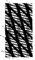
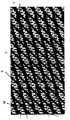
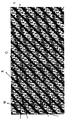
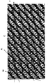
- FIG. 10 shows a printed matter formed from the same image as FIG. 9 obtained by halftone dot division using a conventional method in which a reference point is not provided (not divided).
- three minimum unit areas for gradation expression are arranged in the vertical direction.
- 5 pixels are drawn in an area where gradation expression is performed.
- the angles of each plate are: C plate: 15 °, M plate: 75 °, Y plate: 0 °, K plate: 45 °.
- the C plate and the Y plate intersect to surround a portion expressed in green. Since the angles of the two plates are close, it can be confirmed that the range that is mixed and green is longer in the horizontal direction, and the portion expressed in green is wide.
- the parts expressed in green are arranged in the vertical direction, and are also generated at a constant cycle in the horizontal direction.
- the Y plate does not intersect with other colors, and surrounds a conspicuous part because of the white background.
- the C plate at the same position in the horizontal direction is painted with the K plate, and since the angles are close to the horizontal, the Y plate drawn together is conspicuous.
- the parts reproduced in this way are also arranged in the vertical direction, and are also generated at a constant cycle in the horizontal direction.
- the M plate surrounds the portion that occurs in a short period without intersecting with other colors.
- C and Y in the vertical direction are filled with K and are drawn while many white background portions are generated. Portions where M is drawn in this short cycle occur in a certain range, are arranged in the vertical direction, and are also generated in the horizontal direction at a certain cycle.
- the area where the white background is conspicuous is enclosed.
- the C, M, and Y plates are filled with the K plate, and the background color is white.
- Such portions are also arranged in the vertical direction, and are also generated at a constant cycle in the horizontal direction. In addition to this, there are many parts that are expressed in the same way in the vertical direction and that occur in the horizontal direction at regular intervals.
- FIG. 10 shows a printed matter formed from the same image as in FIG. 9 in which halftone dot division is performed using a method in which the reference points of all the plates are set at two locations.
- three minimum unit areas for gradation expression are arranged in the vertical direction.
- 5 pixels are drawn in an area where gradation expression is performed.
- the angles of each plate are: C plate: 15 °, M plate: 75 °, Y plate: 0 °, K plate: 45 °.
- the C plate and the Y plate intersect to surround a portion expressed in green. Since the angles of the two plates are close, it can be confirmed that the range that is mixed and green is longer in the horizontal direction, and the portion expressed in green is wide.
- the parts expressed in green are arranged in the vertical direction, and are also generated at a constant cycle in the horizontal direction.
- the Y plate does not intersect with other colors, and surrounds a conspicuous part because of the white background.
- the C plate at the same position in the horizontal direction is painted with the K plate, and since the angles are close to the horizontal, the Y plate drawn together is conspicuous.
- the parts reproduced in this way are also arranged in the vertical direction, and are also generated at a constant cycle in the horizontal direction.
- the M plate surrounds a portion that occurs in a short period without intersecting with other colors.
- C and Y in the vertical direction are filled with K and are drawn while many white background portions are generated. Portions where M is drawn in this short cycle occur in a certain range, are arranged in the vertical direction, and are also generated in the horizontal direction at a certain cycle.
- the C version surrounds a conspicuous portion without interfering with other colors.
- Y in the vertical direction is filled with K, and C is particularly noticeable.
- Such portions are also arranged in the vertical direction, and are also generated at a constant cycle in the horizontal direction.
- the halftone image print product 3 is configured such that, in the minimum unit area 3a for gradation expression, the number of reference points in at least some of the color plates is set to the number of reference points in other color plates.
- the gradient of the alignment of the reference points in each color plate is set to be different in each color plate, and in each color plate, the pixel position of the reference point is preferentially assigned as a pixel to be printed, When the number of halftone dots to be printed exceeds the number of reference point locations, the remaining number of pixels to be printed is adjacent to the reference point pixel in the vertical direction (longitudinal direction of the elongated image) with each reference point as the center.
- halftone printing is performed by an amplitude modulation (AM) screen in the longitudinal direction around a plurality of reference positions (reference points) for each color plate, so that the roughness of the image is reduced from the lenticular lens 4 side.
- the halftone image printed matter 3 can be observed three-dimensionally in a state where the occurrence of moire is reduced.
- the printing area is expanded by the continuous printing of pixels around the reference position (reference point), and halftone printing is performed by a printing press or printing press. Can be more reliably performed, and gradation expression that makes full use of the resolution of a printing press or printing press can be realized. Furthermore, the apparent roughness can be reduced without reducing the number of gradations that can be expressed.
- the present invention is not limited to the above embodiment.
- the reference points are arranged at almost equal intervals in the minimum unit region 3a, but may be arranged so as not to be intentionally arranged at equal intervals.
- the pixels are printed so as to extend in the vertical direction around the reference point pixel. However, as many pixels as the required number of pixels upward or downward from the reference point pixel are used. You can print. At this time, if the number of pixels to be printed remains even when the pixels to be printed reach the uppermost pixel among the pixels arranged in the vertical direction, the pixels are directed upward from the lowest pixel. If the number of pixels to be printed remains, even if the pixels to be printed reach the lowest pixel among the pixels arranged in the vertical direction, In this case, a pixel to be printed downward from the uppermost pixel may be added.
- a halftone dot image print in which elongated images corresponding to the number of image data are arranged directly below the half cylindrical lens according to the shape of each semicylindrical lens.
- the arrangement is not limited to this as long as the dot image printed material corresponds.
- the corresponding range of the halftone image printed material may be arranged in a range that can be seen through the semicylindrical lens from the observation point.
- the width of the halftone image print corresponding to the semicylindrical lens changes depending on the position of the semicylindrical lens even if the pitch of the semicylindrical lens is constant.
- rectangular pixels are used as halftone dots.
- dot-like halftone dots may be used as long as adjacent halftone dots are closely arranged.
- 1a to 1d (1) ... Stereo camera, 2 ... Subject, 3 ... halftone image printed matter, 3a: Minimum unit area for gradation expression; 4 ... Lenticular lens, 4a ... the back, 4b ... a semi-cylindrical lens, 5 ... 3D image printed matter, 8 ... lighting means, 9 ... Backlight device, 11 ... Light diffusion plate, 12 ... Transparent plate, 13 ... Frame, 15 ... Stereoscopic image display device
Landscapes
- Physics & Mathematics (AREA)
- General Physics & Mathematics (AREA)
- Optics & Photonics (AREA)
- Printing Methods (AREA)
Abstract
【課題】モアレの発生をより低減させ、見た目の精細さを向上させた立体画像印刷物、及びそれを用いた立体画像印刷表示装置を提供する 【解決手段】立体画像印刷物5は、レンチキュラーレンズ4と、レンチキュラーレンズ4の背面4aに貼付される網点画像印刷物3とにより構成される。網点画像印刷物3の細長画像は、階調表現を行う最小単位の領域3aにおいて、色版ごとに複数の基準点を中心として長手方向に振幅変調スクリーンにより網点印刷されている。各色版のうち、少なくとも一部の色版における基準点の数を、他の色版における基準点の数と異なるように設定し、各色版における基準点の並びの勾配を各色版で異なるように設定する。立体画像印刷物5の背面にはバックライト装置9が配置され、明るく照明される。
Description
本発明は、レンチキュラーレンズを用いた立体画像印刷物を備える立体画像印刷表示装置に関し、特に、レンチキュラーレンズの背面に配置され、濃度階調表現に係る網点画像印刷物の網点印刷技術に関する。
従来、商品やサービスの広告用に、ポスターや広告印刷物を見る者に目立たせるため、商品やサービスの象徴的な画像を立体的に見えるようレンチキュラーレンズを用いた立体画像印刷物が利用されている。このような立体画像印刷物は、異なる角度から撮影された画像が、短冊状に分割されて、レンチキュラーレンズの背面にその半円筒状レンズに沿って配列されたものである(例えば、特許文献1、2)。
レンチキュラーレンズの背面に配置される画像の網点印刷方式としては、FM(周波数変調)スクリーン法とAM(振幅変調)スクリーン法とが知られている(例えば、特許文献1)。FMスクリーン法は、一定の大きさを持った網点の密度によって濃度階調を表現する方法であり、AMスクリーン法は、網点の大きさによって濃度階調を表現する方法である。また、細長画像の網点印刷として、階調表現を行う最小単位の領域において、その中央を中心として長手方向にAMスクリーンにより網点印刷する方法や、網点が個々に離間するようにFMスクリーンにより網点印刷する方法が提案されている(特許文献2)。
また、本出願人は、下記特許文献3において、モアレ(干渉縞)の発生を抑えるなどのために、C版、M版、Y版、K版などの色版ごとに網点角度を施し、細長画像において、隣接する網点同士が接するように網点印刷することを提案している。また、本出願人は、下記特許文献4において、画像の粗さを低減するなどのために、網点画像印刷物の細長画像を、階調表現を行う最小単位の領域において、色版ごとに複数の基準位置を中心として長手方向に振幅変調スクリーンにより網点印刷することを提案している。
しかしながら、特許文献3の立体画像印刷物では、網点のパターンによってはモアレの発生を低減させることが十分でない場合がある。また、特許文献4の立体画像印刷物では、網点の大きさを小さくすることで、見た目の精細さは向上するが、網点のパターンによっては、画像全体にざらつきが若干生じる場合がある。
そこで、本発明は、色の混ざり具合をより向上させ、モアレの発生をより低減させ、見た目の精細さを向上させ、画像のざらつき感を低減させた立体画像印刷物、及びそれを用いた立体画像印刷表示装置を提供することを目的とする。
本発明に係る立体画像印刷物は、複数の半円筒状レンズが連続的に配列されてなるレンチキュラーレンズと、前記レンチキュラーレンズの背面に配置され、各半円筒状レンズに対応して複数の細長画像が連続的に配列され、網点印刷された網点画像印刷物とを備えており、前記網点画像印刷物は、色版毎に、階調表現を行う最小単位の単位領域が複数配列されて形成されているとともに当該単位領域内に前記網点印刷される画素の基準点として優先的に割り当てられた画素を有し、各色版のうち、少なくとも一部の色版における前記単位領域の基準点の数が、他の色版における当該基準点の数とは異なり、かつ、各色版における基準点の並びの勾配が、他の色版の各基準点における並びの勾配とは異なり、前記色版毎にかつ単位領域毎に、前記階調表現に基づいて、前記基準点から前記細長画像の長手方向に連続的に延在する各画素が、印刷されていることを特徴とする。
この立体画像印刷物によれば、色の混ざり具合を向上させ、モアレの発生を低減させ、見た目の精細さを向上させ、画像のざらつき感を低減させることができる。
上記立体画像印刷物において、前記色版毎にかつ単位領域毎に、前記階調表現に基づいて、各基準点を中心として前記基準点から前記細長画像の長手方向の両方向に連続的に延在する各画素が、印刷されているように構成するとよい。この構成により、さらに、色の混ざり具合を向上させ、モアレの発生を低減させ、見た目の精細さを向上させ、画像のざらつき感を低減させることができる。
本発明に係る立体画像印刷表示装置は、上記立体画像印刷物と、前記立体画像印刷物における前記網点画像印刷物を背面から照射するためのバックライト装置とを備えていることを特徴とする。この構成により、バックライト装置の照明により網点画像印刷物を明るい状態で観察することができる。
また、本発明に係る立体画像印刷物における網点画像印刷物の印刷方法は、複数の半円筒状レンズが連続的に配列されてなるレンチキュラーレンズと、前記レンチキュラーレンズの背面に配置され、各半円筒状レンズに対応して複数の細長画像が連続的に配列され、網点印刷された網点画像印刷物とを備える立体画像印刷物における網点画像印刷物の印刷方法であって、各色版毎に複数配列されて形成される階調表現を行う最小単位の単位領域において、各色版のうち、少なくとも一部の色版における前記網点印刷される画素の基準点となる画素の数を、他の色版における基準点の数と異なるように設定し、なおかつ、各色版における各基準点の並びの勾配を他の色版の各基準点における並びの勾配と異なるように設定したうえで、各色版において、前記基準点を優先的に前記網点印刷する画素として割り当てるとともに、各単位領域内に印刷される前記網点印刷すべき画素数が基準点の数を超える場合に、前記基準点から前記細長画像の長手方向にかつ当該基準点に隣接する各画素を前記印刷すべき画素に割り当てて、前記網点画像印刷物を網点印刷することを特徴とする。
上記網点画像印刷物の印刷方法において、各単位領域内に印刷される前記網点印刷すべき画素数が前記基準点の数を超える場合に、各基準点を中心として前記基準点から前記細長画像の長手方向の両方向に順々に当該基準点に隣接する各画素を前記印刷すべき画素に割り当てて、前記網点網点画像印刷物を網点印刷するようにするとよい。
これらの立体画像印刷物における網点画像印刷物の印刷方法により、本発明の立体画像印刷物を印刷することができる。
本発明によれば、色の混ざり具合をより向上させ、モアレの発生をより低減させ、見た目の精細さを向上させ、画像のざらつき感を低減させた立体画像印刷物、及びそれを用いた立体画像印刷表示装置を提供することができる。
以下、図面を参照しながら、本発明に係る立体画像印刷表示装置の好適な実施形態について説明する。
まず、本実施形態に係る立体画像印刷表示装置に用いられる立体画像印刷物について説明する。図1は、立体画像印刷物に用いられる網点画像印刷物3の作製方法を示した図である。図1(A)に示すように、ステレオカメラ1の各カメラ1a、1b、1c、1dを水平に配列するように設置して、被写体2を撮影する。図1(B)は、各カメラ1a~1dによって撮影された画像を示し、図1(B)のB-1は、カメラ1aによって撮影された画像G1、図1(B)のB-2は、カメラ1bによって撮影された画像G2、図1(B)のB-3は、カメラ1cによって撮影された画像G3、図1(B)のB-4は、カメラ1dによって撮影された画像G4である。これらの画像G1~G4は、使用されるレンチキュラーレンズの半円筒状レンズの個数に応じて、縦に分割される。
図1(B)において、B-1の画像G1が分割された画像を左から順に、細長画像s11、s12、s13、…とする。同様に、B-2の画像G2が分割された画像を、細長画像s21、s22、s23、…とし、B-3の画像G3が分割された画像を、細長画像s31、s32、s33、…とし、B-4の画像G4が分割された画像を、細長画像s41、s42、s43、…とする。
そして、図1(C)に示すように、画像G1~G4の各細長画像を一つずつ画像G1~G4の順に配列させる。すなわち、左から順に、
s11、s21、s31、s41、s12、s22、s32、s42、s13、s23、s33、s43、s14、s24、s34、s44、…
と配列する。
s11、s21、s31、s41、s12、s22、s32、s42、s13、s23、s33、s43、s14、s24、s34、s44、…
と配列する。
そのうえで、
s11、s21、s31、s41をグループGr1、
s12、s22、s32、s42をグループGr2、
s13、s23、s33、s43をグループGr3、
s14、s24、s34、s44をグループGr4、
……
とすると、各グループGrをレンチキュラーレンズの半円筒状レンズの背面に配置されて、レンチキュラーレンズの背面全体にわたって配置されるように、上下左右方向に拡大ないし縮小して網点画像印刷物3とする。
s11、s21、s31、s41をグループGr1、
s12、s22、s32、s42をグループGr2、
s13、s23、s33、s43をグループGr3、
s14、s24、s34、s44をグループGr4、
……
とすると、各グループGrをレンチキュラーレンズの半円筒状レンズの背面に配置されて、レンチキュラーレンズの背面全体にわたって配置されるように、上下左右方向に拡大ないし縮小して網点画像印刷物3とする。
次に、図2を用いてレンチキュラーレンズ4の背面4aへの網点画像印刷物3の配置について説明する。図2は、立体画像印刷物5の分解斜視図である。図2に示すように、網点画像印刷物3は、各グループGrが連接されて構成され、各グループGrの細長画像は、レンチキュラーレンズ4における一つの半円筒状レンズ4bの背面に合うように配置されて、背面4aへ貼り合わされる。
続いて、図3を用いて、立体画像印刷物5を備える立体画像印刷表示装置15について説明する。図3は、立体画像印刷表示装置15の分解斜視図である。網点画像印刷物3は、各グループGrをプラスチック製の透明シートに印刷したものである。立体画像印刷物5の網点画像印刷物3側には、蛍光灯などの照明手段8を備えたバックライト装置9が設けられている。この照明手段8により、立体画像印刷物5の背面から光が照射される。そのため、バックライト装置9の照明手段8の照明により、網点画像印刷物3を明るい状態で観察することができる。立体画像印刷物5とバックライト装置9との間には、照明手段8からの光を拡散させるための光拡散板11が配置されている。光拡散板11としては、例えば、乳白色のプレートを用いるとよい。
立体画像印刷物5のレンチキュラーレンズ4側には、レンチキュラーレンズ4を保護するための透明プレート12が配置され、さらに、その外側に、透明プレート12、立体画像印刷物5及び光拡散板11を重ねてバックライト装置9に取り付けるためのフレーム13が配置される。フレーム13は、バックライト装置9に対して係合具(図示しない)により取り付けられる。
なお、透明プレート12は必要に応じて取り付ければよく、フレーム13を用いずに、レンチキュラーレンズ4をバックライト装置9に直接的または間接的に固定するようにしてもよい。網点画像印刷物3を透明シートに印刷する場合には、通常の紙に印刷するよりも、濃度を高く(濃く)印刷するとよい。また、レンチキュラーレンズ4に貼り合わせられる面とは別の透明シート3の面に、反転させた画像を印刷する場合にも、濃度を高く(濃く)印刷することが望ましい。網点画像印刷物3は、薄紙や合成紙など、光を透過しやすい他のものであってもよい。光拡散板11は、必要に応じて配置すればよく、光拡散板11に直接画像を印刷して、網点画像印刷物3を構成させてもよい。また、バックライト装置9の照明手段8は、蛍光灯の他に、LED、有機EL、無機ELでもよく、一般のディスプレイであってもよい。照明手段8が有機ELや無機ELの場合には、網点画像印刷物3あるいは光拡散板11を有機ELないし無機ELの表面に直接貼り付けてもよい。
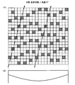
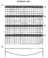
続いて、図4~図8を用いて網点画像印刷物3に網点印刷を行う仕方について説明する。図4~図7の各(A)図は、網点画像印刷物3を作製するにあたって、カラー印刷における各色版、すなわち、それぞれC版、M版、Y版、K版で網点印刷を行う場合の基準位置(以下、「基準点」ともいう。)を説明するための図であり、図4~図7の各(B)図は、網点画像印刷物3に貼付されるレンチキュラーレンズ4の半円筒状レンズ4bの位置関係を説明するための図である。
ここでは、一つの半円筒状レンズ4bの背面に貼付される細長画像が20本あり(20画素)、階調表現を行う最小単位の領域(以下、「最小単位領域」ともいう。)3aとして縦方向の20画素分を用いる場合について説明する。この場合、図4~図7の各(A)図に示すように、20本の細長画像が横方向に配列され、1本の細長画像について、縦方向20画素を用いて、それぞれ、C版、M版、Y版、K版の色版でその階調度に応じて網点を印刷する。なお、印刷された隣接する画素は、互いに接しており、各画素は網点印刷の網点に対応する。
図4(A)に示す例は、C版で網点印刷を行う場合の基準位置(基準点)を説明するための図である。図4(A)に示すように、階調表現を行う最小単位の領域3aにおいて、最小単位領域3aをほぼ等間隔に分けるように基準点を2箇所とする。なおかつ、各最小単位領域3aにおける基準点が左側から右側にかけて約15度(degree)の勾配(網点角度)を形成するように配置する。ここで、符号17の並びの基準点を第1基準並びの基準点と呼び、符号18の並びの基準点を第2基準並びの基準点と呼ぶこととする。
各最小単位領域3aにおいて、C版により網点印刷すべき画素数が決定されれば、まず、優先的に基準点の画素の位置を印刷する画素として割り当てる。網点印刷すべき画素数が基準点箇所数を超える場合は、残りの印刷すべき画素数を、各基準点を中心として基準点の画素に隣接する上下方向(細長画像の長手方向)で順々に割り当てる。
図8は、C版の基準位置(基準位置)を図4(A)に示すように設定した場合の網点印刷の領域を示す例である。
図8に示す例においては、最も左側の最小単位領域3aにおける網点印刷すべき画素数が1画素であったため、優先的に2箇所ある基準点のうち下側の基準点(第1基準並び17の基準点)に印刷すべき画素が割り当てられている。その右隣の最小単位領域3aでは、網点印刷すべき画素数は2画素であったため、優先的に2箇所の基準点にそれぞれ印刷すべき画素が割り当てられている。
最も左から3番目の最小単位領域3aでは、網点印刷すべき画素数は3画素であったため、まず優先的に2箇所の基準点に印刷すべき画素が割り当てられている。そして、基準点箇所数を超える残りの印刷すべき画素が「1画素」なので、第1基準並び17における基準点の上隣の「1画素」が印刷する画素に割り当てられている。
最も左から4番目の最小単位領域3aでは、網点印刷すべき画素数は4画素であったため、まず優先的に2箇所の基準点に印刷すべき画素が割り当てられている。そして、基準点箇所数を超える残りの印刷すべき画素が「2画素」なので、第1基準並び17における基準点の上隣の画素と、第2基準並び18における基準点の上隣の画素に対応する最も下の画素の「2画素」が印刷する画素に割り当てられている。
最も左から5番目の最小単位領域3aでは、網点印刷すべき画素数は5画素であったため、まず優先的に2箇所の基準点に印刷すべき画素が割り当てられている。そして、基準点箇所数を超える残りの印刷すべき画素が「3画素」なので、第1基準並び17における基準点に隣接する上下二つの画素と、第2基準並び18における基準点の上隣の画素の「3画素」が印刷する画素に割り当てられている。
最も左から6番目の最小単位領域3aでは、網点印刷すべき画素数は6画素であったため、まず優先的に2箇所の基準点に印刷すべき画素が割り当てられている。そして、基準点箇所数を超える残りの印刷すべき画素が「4画素」なので、第1基準並び17における基準点に隣接する上下二つの画素と、第2基準並び18における基準点の上隣の画素及び、下隣の画素に対応する最も上の画素の「4画素」が印刷する画素に割り当てられている。
最も左から7番目の最小単位領域3aでは、網点印刷すべき画素数は7画素であったため、まず優先的に2箇所の基準点に印刷すべき画素が割り当てられている。そして、基準点箇所数を超える残りの印刷すべき画素が「5画素」なので、第1基準並び17における基準点に上方向に隣接する二つの画素と下方向に隣接する一つの画素と、第2基準並び18における基準点の上隣の画素及び、下隣の画素に対応する最も上の画素の「5画素」が印刷する画素に割り当てられている。
最も左から8番目以降の最小単位領域3aについても、同様に印刷すべき画素を割り当てる。
このように、各最小単位領域3aにおいて、C版により網点印刷すべき画素数が決定されれば、優先的に基準点の画素の位置を印刷する画素として割り当て、網点印刷すべき画素数が基準点箇所数を超える場合は、残りの印刷すべき画素数を、各基準点を中心として基準点の画素に隣接する上下方向(細長画像の長手方向)で順々に割り当てたうえで、割り当てられた画素に対して、振幅変調スクリーンにより網点印刷を行う。
なお、網点印刷すべき画素数が基準点箇所数を超える場合の残りの印刷すべき画素の位置決定にあたっては、基準点に隣接する画素のうち、上下方向のいずれの方向に隣接する画素を優先的に割り当ててもよく、上下方向の優先性をランダムに設定してもよい。
次に、M版による網点印刷について説明する。図5(A)に示す例は、M版で網点印刷を行う場合の基準位置(基準点)を説明するための図である。
図5(A)に示すように、階調表現を行う最小単位の領域3aにおいて、最小単位領域3aをほぼ等間隔に分けるように基準点を3箇所とする。なおかつ、各最小単位領域3aにおける基準点が左側から右側にかけて約75度(degree)の勾配を形成するように配置する。
M版による網点印刷においても、C版による網点印刷と同様に、各最小単位領域3aにおいて、M版により網点印刷すべき画素数が決定されれば、まず、優先的に基準点の画素の位置を印刷する画素として割り当てる。網点印刷すべき画素数が基準点箇所数を超える場合は、残りの印刷すべき画素数を、各基準点を中心として基準点の画素に隣接する上下方向(細長画像の長手方向)で順々に割り当てる。
次に、Y版による網点印刷について説明する。図6(A)に示す例は、Y版で網点印刷を行う場合の基準位置(基準点)を説明するための図である。
図6(A)に示すように、階調表現を行う最小単位の領域3aにおいて、最小単位領域3aをほぼ等間隔に分けるように基準点を4箇所とする。なおかつ、各最小単位領域3aにおける基準点が左側から右側にかけて水平方向(0度(degree))の勾配を形成するように配置する。
Y版による網点印刷においても、C版,M版による網点印刷と同様に、各最小単位領域3aにおいて、Y版により網点印刷すべき画素数が決定されれば、まず優先的に基準点の画素の位置を印刷する画素として割り当てる。網点印刷すべき画素数が基準点箇所数を超える場合は、残りの印刷すべき画素数を、各基準点を中心として基準点の画素に隣接する上下方向(細長画像の長手方向)で順々に割り当てる。
次に、K版による網点印刷について説明する。図7(A)に示す例は、K版で網点印刷を行う場合の基準位置(基準点)を説明するための図である。
図7(A)に示すように、階調表現を行う最小単位の領域3aにおいて、最小単位領域3aをほぼ等間隔に分けるように基準点を5箇所とする。なおかつ、各最小単位領域3aにおける基準点が左側から右側にかけて約45度(degree)の勾配を形成するように配置する。
K版による網点印刷においても、C版,M版,Y版による網点印刷と同様に、各最小単位領域3aにおいて、Y版により網点印刷すべき画素数が決定されれば、まず優先的に基準点の画素の位置を印刷する画素として割り当てる。網点印刷すべき画素数が基準点箇所数を超える場合は、残りの印刷すべき画素数を、各基準点を中心として基準点の画素に隣接する上下方向(細長画像の長手方向)で順々に割り当てる。
このようにして、各色版について印刷する画素に割り当てられた画素に対して重ねて振幅変調スクリーンにより網点印刷する。ここで、本実施形態においては、各色版の基準点を2~5箇所と異なるように設定し、なおかつ、基準点の並びの勾配を各色版で異なるように設定した。なお、各色版の基準点の数については、複数の色版のうち少なくとも一部で異なるようにするとよい。
また、各色版の基準点の数は、印刷機や刷版機の解像度に応じて適宜設定するとよい。例えば、高精細な刷版機で、1画素単独での描画が困難な場合、またそのような細かな点でのインキの着肉が困難な印刷機の場合には、基準点の数を少なくすることで、印刷すべき画素が互いに隣接して結果的に形成されるひとまとまりの網点がなるべく大きくなるように調整することができる。また、階調表現を行う最小単位の領域3aでの画素数が少ない場合、例えば20画素や30画素の場合、基準点の数を多くすると、1画素単独での描画が多くなる場合もありうるので、基準点の数を少なくして、インキの着肉などの問題を解消するとよい。
[実施例1]
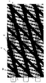
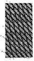
図9は、C、M、Y、K版の全てにおいて、階調表現を行う最小単位の領域の画素数を20、印刷すべき画素数を5画素に設定した場合に、本発明による手法で網点分割したものである。ここでは、階調表現を行う最小単位の領域を縦方向に3つ分並べている。また、各版の勾配(網点角度)は、C版:15°、M版:75°、Y版:0°、K版:45°であり、各版の階調表現を行う最小単位の領域における基準点箇所数は、C版:3、M版:2、Y版:4、K版:5である。
図9は、C、M、Y、K版の全てにおいて、階調表現を行う最小単位の領域の画素数を20、印刷すべき画素数を5画素に設定した場合に、本発明による手法で網点分割したものである。ここでは、階調表現を行う最小単位の領域を縦方向に3つ分並べている。また、各版の勾配(網点角度)は、C版:15°、M版:75°、Y版:0°、K版:45°であり、各版の階調表現を行う最小単位の領域における基準点箇所数は、C版:3、M版:2、Y版:4、K版:5である。
図9に示すように、この状態では、同じ色が垂直方向に並んでおり、水平方向に一定周期で発生する部分が存在するが、版の分割数が異なっているため、その発生部分が分散しており、特定の周期としてみなすことができなくなっている。また、各版の描画部分が細かくなっているため、白地部分が細かく分散されており、特定の色が目立たなくなっている。本手法で網点処理された立体表示用の印刷物に、レンチキュラーシートを重ねて観察しても、モアレが発生していないことが確認された。
[比較例1]
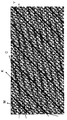
図10~13は、実施例1と同様に、C、M、Y、K版の全てにおいて、階調表現を行う最小単位の領域の画素数を20、印刷すべき画素数が5画素に設定し、従来の基準点を設けない(分割しない)手法で網点分割した図9と同じ画像から形成される印刷物を示したものである。ここでは、階調表現を行う最小単位の領域を縦方向に3つ分並べている。各版で階調表現を行う領域に5画素描画し、各版の角度は、C版:15°、M版:75°、Y版:0°、K版:45°となっている。
図10~13は、実施例1と同様に、C、M、Y、K版の全てにおいて、階調表現を行う最小単位の領域の画素数を20、印刷すべき画素数が5画素に設定し、従来の基準点を設けない(分割しない)手法で網点分割した図9と同じ画像から形成される印刷物を示したものである。ここでは、階調表現を行う最小単位の領域を縦方向に3つ分並べている。各版で階調表現を行う領域に5画素描画し、各版の角度は、C版:15°、M版:75°、Y版:0°、K版:45°となっている。
図10の枠囲い付近に示すように、C版とY版が交差して、緑色に表現されている部分を囲んでいる。2つの版の角度が近いため、混ざり合って緑色になっている範囲が水平方向に長くなり、緑色で表現される箇所が広いことが確認できる。緑色で表現される部分は、縦方向に並んでおり、水平方向にも一定周期で発生してしまっている。
また、図11の枠囲い付近に示すように、Y版が他の色と交わらず、周りが白地のために目立っている部分を囲んでいる。水平方向の同じ位置にあるC版がK版によって塗りつぶされており、さらに角度が水平に近いためまとまって描画されているY版が目立つ。このように再現される部分も、垂直方向に並んでおり、水平方向にも一定周期で発生してしまっている。
また、図12の枠囲い付近に示すように、M版が他の色と交わらず、短周期で発生している部分を囲んでいる。垂直方向にあるCとYがKによって塗りつぶされており、白地部分が多く発生している中で描画されている。この短周期でMが描画される部分は一定の範囲で発生し、垂直方向に並んでおり、水平方向にも一定周期で発生してしまっている。
さらに、図13の枠囲い付近に示すように、白地が目立つ部分を囲んでいる。C、M、Y版がK版で塗りつぶされており、地色の白が多くなっている。このような部分も、垂直方向に並んでおり、水平方向にも一定周期で発生する。これ以外にも、垂直方向で同じように表現され、さらにそれが水平方向に一定周期で発生するような部分が、細かく見ていけば数多くある。
このように従来の基準点を設けない(分割しない)手法で網点処理された立体表示用の印刷物に、レンチキュラーシートを重ねて観察した場合、モアレが発生してそれが認識されてしまう場合がある。これは、レンチキュラーレンズでは、レンズ下部にある印刷物の一部分だけが拡大されて表示されるが、レンズピッチの周期によって拡大される印刷物の一部分と、印刷物の周期的な描画が影響しあうためである。
[比較例2]
図14~17は、実施例1と同様に、C、M、Y、K版の全てにおいて、階調表現を行う最小単位の領域の画素数を20、印刷すべき画素数が5画素に設定し、全ての版の基準点を2箇所に設定した手法で網点分割した図9と同じ画像から形成された印刷物を示したものである。ここでは、階調表現を行う最小単位の領域を縦方向に3つ分並べている。各版で階調表現を行う領域に5画素描画し、各版の角度は、C版:15°、M版:75°、Y版:0°、K版:45°となっている。
図14~17は、実施例1と同様に、C、M、Y、K版の全てにおいて、階調表現を行う最小単位の領域の画素数を20、印刷すべき画素数が5画素に設定し、全ての版の基準点を2箇所に設定した手法で網点分割した図9と同じ画像から形成された印刷物を示したものである。ここでは、階調表現を行う最小単位の領域を縦方向に3つ分並べている。各版で階調表現を行う領域に5画素描画し、各版の角度は、C版:15°、M版:75°、Y版:0°、K版:45°となっている。
図14の枠囲い付近に示すように、C版とY版が交差して、緑色に表現されている部分を囲んでいる。2つの版の角度が近いため、混ざり合って緑色になっている範囲が水平方向に長くなり、緑色で表現される箇所が広いことが確認できる。緑色で表現される部分は、縦方向に並んでおり、水平方向にも一定周期で発生してしまっている。
また、図15の枠囲い付近に示すように、Y版が他の色と交わらず、周りが白地のために目立っている部分を囲んでいる。水平方向の同じ位置にあるC版がK版によって塗りつぶされており、さらに角度が水平に近いためまとまって描画されているY版が目立つ。このように再現される部分も、垂直方向に並んでおり、水平方向にも一定周期で発生してしまっている。
また、図16の枠囲い付近に示すように、M版が他の色と交わらず、短周期で発生している部分を囲んでいる。垂直方向にあるCとYがKによって塗りつぶされており、白地部分が多く発生している中で描画されている。この短周期でMが描画される部分は一定の範囲で発生し、垂直方向に並んでおり、水平方向にも一定周期で発生してしまっている。
さらに、図17の枠囲い付近に示すように、C版が他の色と交わらず目立つ部分を囲んでいる。垂直方向にあるYがKによって塗りつぶされており、特にCが目立っている。このような部分も、垂直方向に並んでおり、水平方向にも一定周期で発生する。これ以外にも、垂直方向で同じように表現され、さらにそれが水平方向に一定周期で発生するような部分が、細かく見ていけば数多くある。
このように基準点の数を全ての版で等しくした手法で網点処理された立体表示用の印刷物に、レンチキュラーシートを重ねて観察した場合、モアレが発生してそれが認識されてしまう場合がある。これは、レンチキュラーレンズでは、レンズ下部にある印刷物の一部分だけが拡大されて表示されるが、レンズピッチの周期によって拡大される印刷物の一部分と、印刷物の周期的な描画が影響しあうためである。
(本実施形態による作用効果)
このように、網点画像印刷物3は、階調表現を行う最小単位の領域3aにおいて、各色版のうち、少なくとも一部の色版における基準点の数を、他の色版における基準点の数と異なるように設定し、なおかつ、各色版における基準点の並びの勾配を各色版で異なるように設定したうえで、各色版において、優先的に基準点の画素の位置を印刷する画素として割り当て、網点印刷すべき画素数が基準点箇所数を超える場合に、残りの印刷すべき画素数を、各基準点を中心として基準点の画素に対して上下方向(細長画像の長手方向)に隣接するよう割り当てて、振幅変調スクリーンにより網点印刷される。そのため、色版ごとに複数の基準位置(基準点)を中心として長手方向に振幅変調(AM)スクリーンにより網点印刷されることになるため、レンチキュラーレンズ4側から画像の粗さが低減されるとともに、モアレの発生を低減させた状態で、立体的に網点画像印刷物3を観察することができる。また、網点画像印刷物3の地色が部分的に集中してしまうことを防止することができ、各色の混ざり具合を向上させ、より自然な色合いを表現することができる。また、基準点は、連続的でほぼ直線状に配置されているため、基準位置(基準点)周辺に印刷する画素が連続することで印刷領域が広がり、印刷機や刷版機による網点印刷の着肉をより確実に行うことができるようになり、印刷機や刷版機の解像度を十分に活かした階調表現が可能となる。さらには、表現できる階調数を減らすことなく、見た目の粗さを低減することができる。
このように、網点画像印刷物3は、階調表現を行う最小単位の領域3aにおいて、各色版のうち、少なくとも一部の色版における基準点の数を、他の色版における基準点の数と異なるように設定し、なおかつ、各色版における基準点の並びの勾配を各色版で異なるように設定したうえで、各色版において、優先的に基準点の画素の位置を印刷する画素として割り当て、網点印刷すべき画素数が基準点箇所数を超える場合に、残りの印刷すべき画素数を、各基準点を中心として基準点の画素に対して上下方向(細長画像の長手方向)に隣接するよう割り当てて、振幅変調スクリーンにより網点印刷される。そのため、色版ごとに複数の基準位置(基準点)を中心として長手方向に振幅変調(AM)スクリーンにより網点印刷されることになるため、レンチキュラーレンズ4側から画像の粗さが低減されるとともに、モアレの発生を低減させた状態で、立体的に網点画像印刷物3を観察することができる。また、網点画像印刷物3の地色が部分的に集中してしまうことを防止することができ、各色の混ざり具合を向上させ、より自然な色合いを表現することができる。また、基準点は、連続的でほぼ直線状に配置されているため、基準位置(基準点)周辺に印刷する画素が連続することで印刷領域が広がり、印刷機や刷版機による網点印刷の着肉をより確実に行うことができるようになり、印刷機や刷版機の解像度を十分に活かした階調表現が可能となる。さらには、表現できる階調数を減らすことなく、見た目の粗さを低減することができる。
なお、本発明は、上記実施形態に限られない。
上記実施形態では、基準点は、最小単位領域3aにおいて、ほぼ等間隔に配置したが、意図的に等間隔にしないように配置してもよい。また、上記実施形態においては、基準点の画素を中心として上下方向に延在するよう画素を印刷したが、基準点の画素を基点として上方向、または下方向に必要な画素数分だけ画素を印刷しても構わない。このとき、印刷すべき画素が、縦方向に配列されている画素の中で、最も上の画素まで達してもなお印刷すべき画素数が残っている場合は、最も下の画素から上方へ向けて印刷する画素を加えていけばよく、また、印刷すべき画素が、縦方向に配列されている画素の中で、最も下の画素まで達してもなお印刷すべき画素数が残っている場合は、最も上の画素から下方へ向けて印刷する画素を加えていけばよい。
また、上記各実施形態では、各半円筒状レンズの形状に合わせて、その直下に画像データ数分の細長画像を配列させた網点画像印刷物を貼り合せたが、各半円筒状レンズと網点画像印刷物とが対応していれば、この配置に限らなくとも良い。例えば、立体画像印刷物の中央上方から立体画像印刷物を観察することを想定し、その観察点から半円筒状レンズを通して見える範囲に、網点画像印刷物の対応する範囲を配置するようにしてもよい。この場合、半円筒状レンズに対応する網点画像印刷物の幅は、半円筒状レンズのピッチが一定であっても、半円筒状レンズの位置によって変化する。
また、上記実施形態では、網点として矩形状の画素を用いたが、隣接する網点同士が接するよう密に配置されるならば、点状の網点であってもよい。
1a~1d(1)…ステレオカメラ、
2…被写体、
3…網点画像印刷物、
3a…階調表現を行う最小単位の領域、
4…レンチキュラーレンズ、
4a…背面、
4b…半円筒状レンズ、
5…立体画像印刷物、
8…照明手段、
9…バックライト装置、
11…光拡散板、
12…透明プレート、
13…フレーム、
15…立体画像印刷表示装置
2…被写体、
3…網点画像印刷物、
3a…階調表現を行う最小単位の領域、
4…レンチキュラーレンズ、
4a…背面、
4b…半円筒状レンズ、
5…立体画像印刷物、
8…照明手段、
9…バックライト装置、
11…光拡散板、
12…透明プレート、
13…フレーム、
15…立体画像印刷表示装置
Claims (5)
- 複数の半円筒状レンズが連続的に配列されてなるレンチキュラーレンズと、
前記レンチキュラーレンズの背面に配置され、各半円筒状レンズに対応して複数の細長画像が連続的に配列され、網点印刷された網点画像印刷物とを備えており、
前記網点画像印刷物は、色版毎に、階調表現を行う最小単位の単位領域が複数配列されて形成されているとともに当該単位領域内に前記網点印刷される画素の基準点として優先的に割り当てられた画素を有し、
各色版のうち、少なくとも一部の色版における前記単位領域の基準点の数が、他の色版における当該基準点の数とは異なり、かつ、各色版における基準点の並びの勾配が、他の色版の各基準点における並びの勾配とは異なり、
前記色版毎にかつ単位領域毎に、前記階調表現に基づいて、前記基準点から前記細長画像の長手方向に連続的に延在する各画素が、印刷されていることを特徴とする立体画像印刷物。 - 前記色版毎にかつ単位領域毎に、前記階調表現に基づいて、各基準点を中心として前記基準点から前記細長画像の長手方向の両方向に連続的に延在する各画素が、印刷されていることを特徴とする請求項1に記載の立体画像印刷物。
- 請求項1又は2に記載の立体画像印刷物と、
前記立体画像印刷物における前記網点画像印刷物を背面から照射するためのバックライト装置と、
を備えていることを特徴とする立体画像印刷表示装置。 - 複数の半円筒状レンズが連続的に配列されてなるレンチキュラーレンズと、
前記レンチキュラーレンズの背面に配置され、各半円筒状レンズに対応して複数の細長画像が連続的に配列され、網点印刷された網点画像印刷物とを備える立体画像印刷物における網点画像印刷物の印刷方法であって、
各色版毎に複数配列されて形成される階調表現を行う最小単位の単位領域において、各色版のうち、少なくとも一部の色版における前記網点印刷される画素の基準点となる画素の数を、他の色版における基準点の数と異なるように設定し、なおかつ、各色版における各基準点の並びの勾配を他の色版の各基準点における並びの勾配と異なるように設定したうえで、
各色版において、前記基準点を優先的に前記網点印刷する画素として割り当てるとともに、各単位領域内に印刷される前記網点印刷すべき画素数が基準点の数を超える場合に、前記基準点から前記細長画像の長手方向にかつ当該基準点に隣接する各画素を前記印刷すべき画素に割り当てて、前記網点画像印刷物を網点印刷することを特徴とする立体画像印刷物における網点画像印刷物の印刷方法。 - 各単位領域内に印刷される前記網点印刷すべき画素数が前記基準点の数を超える場合に、各基準点を中心として前記基準点から前記細長画像の長手方向の両方向に順々に当該基準点に隣接する各画素を前記印刷すべき画素に割り当てて、前記網点画像印刷物を網点印刷することを特徴とする請求項4に記載の立体画像印刷物における網点画像印刷物の印刷方法。
Applications Claiming Priority (2)
| Application Number | Priority Date | Filing Date | Title |
|---|---|---|---|
| JP2010028453 | 2010-02-12 | ||
| JP2010-028453 | 2010-11-29 |
Publications (1)
| Publication Number | Publication Date |
|---|---|
| WO2011099211A1 true WO2011099211A1 (ja) | 2011-08-18 |
Family
ID=44367503
Family Applications (1)
| Application Number | Title | Priority Date | Filing Date |
|---|---|---|---|
| PCT/JP2010/070934 Ceased WO2011099211A1 (ja) | 2010-02-12 | 2010-11-24 | 立体画像印刷物、立体画像印刷表示装置、及び立体画像印刷物における網点画像印刷物の印刷方法 |
Country Status (1)
| Country | Link |
|---|---|
| WO (1) | WO2011099211A1 (ja) |
Cited By (2)
| Publication number | Priority date | Publication date | Assignee | Title |
|---|---|---|---|---|
| WO2018188134A1 (zh) * | 2017-04-12 | 2018-10-18 | 深圳市华星光电技术有限公司 | 一种彩色色阻的制作方法 |
| CN115079431A (zh) * | 2021-03-12 | 2022-09-20 | 欧姆龙株式会社 | 导光板、显示装置、输入装置、以及具有显示装置的设备 |
Citations (4)
| Publication number | Priority date | Publication date | Assignee | Title |
|---|---|---|---|---|
| JPH0961950A (ja) * | 1995-08-25 | 1997-03-07 | Dainippon Printing Co Ltd | 立体画像印刷物 |
| JP2006259645A (ja) * | 2005-03-18 | 2006-09-28 | Tokyo Univ Of Agriculture & Technology | カラー立体視印刷物およびモノクロ立体視印刷物 |
| JP3139498U (ja) * | 2007-11-22 | 2008-02-21 | 大日本印刷株式会社 | 立体画像印刷物 |
| JP2009163035A (ja) * | 2008-01-08 | 2009-07-23 | Dainippon Printing Co Ltd | 立体画像印刷物 |
-
2010
- 2010-11-24 WO PCT/JP2010/070934 patent/WO2011099211A1/ja not_active Ceased
Patent Citations (4)
| Publication number | Priority date | Publication date | Assignee | Title |
|---|---|---|---|---|
| JPH0961950A (ja) * | 1995-08-25 | 1997-03-07 | Dainippon Printing Co Ltd | 立体画像印刷物 |
| JP2006259645A (ja) * | 2005-03-18 | 2006-09-28 | Tokyo Univ Of Agriculture & Technology | カラー立体視印刷物およびモノクロ立体視印刷物 |
| JP3139498U (ja) * | 2007-11-22 | 2008-02-21 | 大日本印刷株式会社 | 立体画像印刷物 |
| JP2009163035A (ja) * | 2008-01-08 | 2009-07-23 | Dainippon Printing Co Ltd | 立体画像印刷物 |
Cited By (2)
| Publication number | Priority date | Publication date | Assignee | Title |
|---|---|---|---|---|
| WO2018188134A1 (zh) * | 2017-04-12 | 2018-10-18 | 深圳市华星光电技术有限公司 | 一种彩色色阻的制作方法 |
| CN115079431A (zh) * | 2021-03-12 | 2022-09-20 | 欧姆龙株式会社 | 导光板、显示装置、输入装置、以及具有显示装置的设备 |
Similar Documents
| Publication | Publication Date | Title |
|---|---|---|
| KR101163085B1 (ko) | 스위칭가능한 2d/3d 디스플레이 | |
| CN103620666B (zh) | 光输出面板和具有该光输出面板的设备 | |
| CA2902834C (en) | Autostereoscopic display device | |
| AU2013352469B2 (en) | Slant lens interlacing | |
| JP2014511501A (ja) | 自動立体視表示装置 | |
| JP2015181284A (ja) | 自動立体視表示装置 | |
| US20140307024A1 (en) | Stereoscopic print | |
| CN105607271A (zh) | 一种显示模组、显示装置及其驱动方法 | |
| US9052518B2 (en) | Slant lens interlacing with linearly arranged sets of lenses | |
| WO2011099211A1 (ja) | 立体画像印刷物、立体画像印刷表示装置、及び立体画像印刷物における網点画像印刷物の印刷方法 | |
| CN103984105A (zh) | 影像分层组合结构 | |
| CN114743465A (zh) | 一种发光像素排布结构、显示面板及电子设备 | |
| CN105629489A (zh) | 3d显示屏及3d显示装置 | |
| CN201950976U (zh) | Rgb立体印刷色版 | |
| JP5040858B2 (ja) | 立体画像印刷物 | |
| JP5343681B2 (ja) | 立体画像印刷表示装置 | |
| JP5246013B2 (ja) | 立体画像印刷表示装置 | |
| LU103091B1 (en) | Display device and method to manufacture the display device | |
| WO2009087810A1 (ja) | 立体画像印刷物 | |
| WO2014173853A1 (en) | Auto-stereoscopic display device with a lenticular sheet slanted with respect to the column of colour sub-pixels | |
| CA2950253C (en) | Slant lens interlacing with linearly arranged lenses | |
| JP3102744U (ja) | バックライト型ディスプレイ用印刷物 | |
| CN106683575A (zh) | 塑胶薄膜层叠点阵分布部分透明孔径的led彩屏屏罩 | |
| CN111781744A (zh) | 基于渐变节距矩形针孔阵列的3d显示装置 | |
| JP2014024287A (ja) | 装飾表示体、装飾表示方法および装飾表示システム |
Legal Events
| Date | Code | Title | Description |
|---|---|---|---|
| 121 | Ep: the epo has been informed by wipo that ep was designated in this application |
Ref document number: 10845802 Country of ref document: EP Kind code of ref document: A1 |
|
| NENP | Non-entry into the national phase |
Ref country code: DE |
|
| 122 | Ep: pct application non-entry in european phase |
Ref document number: 10845802 Country of ref document: EP Kind code of ref document: A1 |
|
| NENP | Non-entry into the national phase |
Ref country code: JP |