WO2011093637A2 - Battery pack having outstanding structural stability - Google Patents
Battery pack having outstanding structural stability Download PDFInfo
- Publication number
- WO2011093637A2 WO2011093637A2 PCT/KR2011/000535 KR2011000535W WO2011093637A2 WO 2011093637 A2 WO2011093637 A2 WO 2011093637A2 KR 2011000535 W KR2011000535 W KR 2011000535W WO 2011093637 A2 WO2011093637 A2 WO 2011093637A2
- Authority
- WO
- WIPO (PCT)
- Prior art keywords
- battery
- battery pack
- end plate
- battery module
- modules
- Prior art date
Links
Images


Classifications
-
- H—ELECTRICITY
- H01—ELECTRIC ELEMENTS
- H01M—PROCESSES OR MEANS, e.g. BATTERIES, FOR THE DIRECT CONVERSION OF CHEMICAL ENERGY INTO ELECTRICAL ENERGY
- H01M50/00—Constructional details or processes of manufacture of the non-active parts of electrochemical cells other than fuel cells, e.g. hybrid cells
- H01M50/50—Current conducting connections for cells or batteries
-
- B—PERFORMING OPERATIONS; TRANSPORTING
- B60—VEHICLES IN GENERAL
- B60L—PROPULSION OF ELECTRICALLY-PROPELLED VEHICLES; SUPPLYING ELECTRIC POWER FOR AUXILIARY EQUIPMENT OF ELECTRICALLY-PROPELLED VEHICLES; ELECTRODYNAMIC BRAKE SYSTEMS FOR VEHICLES IN GENERAL; MAGNETIC SUSPENSION OR LEVITATION FOR VEHICLES; MONITORING OPERATING VARIABLES OF ELECTRICALLY-PROPELLED VEHICLES; ELECTRIC SAFETY DEVICES FOR ELECTRICALLY-PROPELLED VEHICLES
- B60L50/00—Electric propulsion with power supplied within the vehicle
- B60L50/50—Electric propulsion with power supplied within the vehicle using propulsion power supplied by batteries or fuel cells
- B60L50/60—Electric propulsion with power supplied within the vehicle using propulsion power supplied by batteries or fuel cells using power supplied by batteries
- B60L50/64—Constructional details of batteries specially adapted for electric vehicles
-
- B—PERFORMING OPERATIONS; TRANSPORTING
- B60—VEHICLES IN GENERAL
- B60L—PROPULSION OF ELECTRICALLY-PROPELLED VEHICLES; SUPPLYING ELECTRIC POWER FOR AUXILIARY EQUIPMENT OF ELECTRICALLY-PROPELLED VEHICLES; ELECTRODYNAMIC BRAKE SYSTEMS FOR VEHICLES IN GENERAL; MAGNETIC SUSPENSION OR LEVITATION FOR VEHICLES; MONITORING OPERATING VARIABLES OF ELECTRICALLY-PROPELLED VEHICLES; ELECTRIC SAFETY DEVICES FOR ELECTRICALLY-PROPELLED VEHICLES
- B60L50/00—Electric propulsion with power supplied within the vehicle
- B60L50/50—Electric propulsion with power supplied within the vehicle using propulsion power supplied by batteries or fuel cells
- B60L50/60—Electric propulsion with power supplied within the vehicle using propulsion power supplied by batteries or fuel cells using power supplied by batteries
- B60L50/66—Arrangements of batteries
-
- H—ELECTRICITY
- H01—ELECTRIC ELEMENTS
- H01M—PROCESSES OR MEANS, e.g. BATTERIES, FOR THE DIRECT CONVERSION OF CHEMICAL ENERGY INTO ELECTRICAL ENERGY
- H01M10/00—Secondary cells; Manufacture thereof
- H01M10/02—Details
-
- H—ELECTRICITY
- H01—ELECTRIC ELEMENTS
- H01M—PROCESSES OR MEANS, e.g. BATTERIES, FOR THE DIRECT CONVERSION OF CHEMICAL ENERGY INTO ELECTRICAL ENERGY
- H01M50/00—Constructional details or processes of manufacture of the non-active parts of electrochemical cells other than fuel cells, e.g. hybrid cells
- H01M50/10—Primary casings, jackets or wrappings of a single cell or a single battery
-
- H—ELECTRICITY
- H01—ELECTRIC ELEMENTS
- H01M—PROCESSES OR MEANS, e.g. BATTERIES, FOR THE DIRECT CONVERSION OF CHEMICAL ENERGY INTO ELECTRICAL ENERGY
- H01M50/00—Constructional details or processes of manufacture of the non-active parts of electrochemical cells other than fuel cells, e.g. hybrid cells
- H01M50/20—Mountings; Secondary casings or frames; Racks, modules or packs; Suspension devices; Shock absorbers; Transport or carrying devices; Holders
- H01M50/204—Racks, modules or packs for multiple batteries or multiple cells
- H01M50/207—Racks, modules or packs for multiple batteries or multiple cells characterised by their shape
- H01M50/209—Racks, modules or packs for multiple batteries or multiple cells characterised by their shape adapted for prismatic or rectangular cells
-
- H—ELECTRICITY
- H01—ELECTRIC ELEMENTS
- H01M—PROCESSES OR MEANS, e.g. BATTERIES, FOR THE DIRECT CONVERSION OF CHEMICAL ENERGY INTO ELECTRICAL ENERGY
- H01M50/00—Constructional details or processes of manufacture of the non-active parts of electrochemical cells other than fuel cells, e.g. hybrid cells
- H01M50/20—Mountings; Secondary casings or frames; Racks, modules or packs; Suspension devices; Shock absorbers; Transport or carrying devices; Holders
- H01M50/249—Mountings; Secondary casings or frames; Racks, modules or packs; Suspension devices; Shock absorbers; Transport or carrying devices; Holders specially adapted for aircraft or vehicles, e.g. cars or trains
-
- H—ELECTRICITY
- H01—ELECTRIC ELEMENTS
- H01M—PROCESSES OR MEANS, e.g. BATTERIES, FOR THE DIRECT CONVERSION OF CHEMICAL ENERGY INTO ELECTRICAL ENERGY
- H01M6/00—Primary cells; Manufacture thereof
- H01M6/42—Grouping of primary cells into batteries
-
- Y—GENERAL TAGGING OF NEW TECHNOLOGICAL DEVELOPMENTS; GENERAL TAGGING OF CROSS-SECTIONAL TECHNOLOGIES SPANNING OVER SEVERAL SECTIONS OF THE IPC; TECHNICAL SUBJECTS COVERED BY FORMER USPC CROSS-REFERENCE ART COLLECTIONS [XRACs] AND DIGESTS
- Y02—TECHNOLOGIES OR APPLICATIONS FOR MITIGATION OR ADAPTATION AGAINST CLIMATE CHANGE
- Y02E—REDUCTION OF GREENHOUSE GAS [GHG] EMISSIONS, RELATED TO ENERGY GENERATION, TRANSMISSION OR DISTRIBUTION
- Y02E60/00—Enabling technologies; Technologies with a potential or indirect contribution to GHG emissions mitigation
- Y02E60/10—Energy storage using batteries
-
- Y—GENERAL TAGGING OF NEW TECHNOLOGICAL DEVELOPMENTS; GENERAL TAGGING OF CROSS-SECTIONAL TECHNOLOGIES SPANNING OVER SEVERAL SECTIONS OF THE IPC; TECHNICAL SUBJECTS COVERED BY FORMER USPC CROSS-REFERENCE ART COLLECTIONS [XRACs] AND DIGESTS
- Y02—TECHNOLOGIES OR APPLICATIONS FOR MITIGATION OR ADAPTATION AGAINST CLIMATE CHANGE
- Y02T—CLIMATE CHANGE MITIGATION TECHNOLOGIES RELATED TO TRANSPORTATION
- Y02T10/00—Road transport of goods or passengers
- Y02T10/60—Other road transportation technologies with climate change mitigation effect
- Y02T10/70—Energy storage systems for electromobility, e.g. batteries
-
- Y—GENERAL TAGGING OF NEW TECHNOLOGICAL DEVELOPMENTS; GENERAL TAGGING OF CROSS-SECTIONAL TECHNOLOGIES SPANNING OVER SEVERAL SECTIONS OF THE IPC; TECHNICAL SUBJECTS COVERED BY FORMER USPC CROSS-REFERENCE ART COLLECTIONS [XRACs] AND DIGESTS
- Y10—TECHNICAL SUBJECTS COVERED BY FORMER USPC
- Y10S—TECHNICAL SUBJECTS COVERED BY FORMER USPC CROSS-REFERENCE ART COLLECTIONS [XRACs] AND DIGESTS
- Y10S903/00—Hybrid electric vehicles, HEVS
- Y10S903/902—Prime movers comprising electrical and internal combustion motors
- Y10S903/903—Prime movers comprising electrical and internal combustion motors having energy storing means, e.g. battery, capacitor
- Y10S903/904—Component specially adapted for hev
- Y10S903/907—Electricity storage, e.g. battery, capacitor
Definitions
- the present invention relates to a battery pack having excellent structural stability, and more particularly, a battery module array in which battery modules are arranged in two or more sides, a base plate in which battery modules are stacked vertically, and a front surface of the battery module assembly. And a pair of main members respectively disposed at the rear and rear surfaces, a pair of end plates in close contact with the front and rear surfaces of the battery module assembly, and a supporting bar connecting the upper or side sides of the end plates.
- the plate relates to a battery pack having a structure that is integrally formed with a size corresponding to the front or rear surface of the battery module assembly so as to minimize deformation of the battery pack against vibration in the vertical direction.
- the secondary battery In order to use the secondary battery as a power source such as EV and HEV, a high output large capacity is required.
- a plurality of small secondary batteries (unit cells) are connected in series, or in some cases, a battery module connected in series and in parallel. And a battery pack.
- such a battery pack is a structure for protecting battery modules in which secondary batteries are built, and has various forms depending on the type of the target vehicle or the mounting position of the vehicle.
- a structure for effectively fixing a large capacity battery module is a structure based on a supporting bar and an end plate. This structure has an advantage of minimizing the movement of the battery module even when a load is applied in the direction of the supporting bar, but for this purpose, there is a problem that the rigidity of the supporting bar and the end plate must be sufficiently secured.
- Figure 1 is a perspective view of a conventional battery pack consisting of one battery module by way of example.
- the battery pack 100 includes unit modules 10 in which secondary batteries are built, a base plate 20, a pair of end plates 30, and a supporting bar 40. .
- the unit modules 10 are vertically stacked on the upper part of the base plate 20, and the end plates 30 are outer surfaces of the outermost unit modules 10 with the lower end fixed to the base plate 20. It is in close contact with.
- the supporting bar 40 connects the upper both sides of the end plates 30 to interconnect and support the pair of end plates 30.
- the battery pack having the above structure has a small capacity because only one battery module is used, it is difficult to apply to an external device such as a vehicle requiring a high output and a large capacity battery pack.
- the battery pack for a hybrid electric vehicle has a variety of forms according to the type of the target vehicle or the mounting position of the vehicle in order to reliably protect the assembly of battery cells.
- battery packs mounted in the space below the trunk or between the bottom of the rear seat and the trunk generally have a bucket structure.
- the battery pack since the battery pack is positioned below the fastening position with the vehicle body, the battery pack is supported by the main member and the base plate, and the structure in which the end plate and the supporting bar are positioned front and back to prevent deformation of the battery pack in the front and rear directions. need.
- the main member is bent in a bucket shape, and thus the structural stability of the entire battery pack is determined according to the rigidity of the main member.
- the main member supporting the load has a bucket type, and the battery modules are arranged in two rows on the base plate, the depth and thickness of the flange of the main member While maintaining the structural stability of the battery pack having a specific structure is improved is a very necessary situation.
- the present invention aims to solve the problems of the prior art as described above and the technical problems that have been requested from the past.
- the battery module is composed of a battery module array, the base plate, the main member, the end plate, and the support bar is arranged in two or more rows side, the end plate is the front or It is formed integrally with the size corresponding to the rear surface, to provide a battery pack structure that can minimize the deformation of the battery pack to the vibration in the vertical direction.
- Still another object of the present invention is to provide a battery pack structure which can be stably mounted in a vehicle and minimize the volume occupied in the vehicle by forming a partial structure of the battery pack using some forms of the vehicle.
- a battery module array in which battery modules themselves or two or more battery cells are stacked vertically with unit modules in which two or more battery cells are built and stacked in two or more rows;
- a pair of main members each of which is disposed on the front and rear surfaces of the battery module assembly to support the loads of the battery modules, the both ends of which are fastened to an external device;
- a pair of end plates in close contact with the front and rear surfaces of the battery module assembly with the bottom fixed to the base plate;
- a supporting bar connecting the upper or side sides of the end plates to mutually support the end plates
- the end plate has a structure that is integrally formed with a size corresponding to the front or rear side of the battery module assembly so as to minimize deformation of the battery pack against vibration in the vertical direction.
- the battery pack according to the present invention since the end plate is formed in a size corresponding to the front or rear of the battery module arrangement, it is possible to reliably reinforce the bending rigidity of the main member, the entire battery pack against the vertical vibration The structural stability of the can be sufficiently secured.
- the battery pack can be easily mounted on the external device even if the battery pack is located below the fastening position with the external device.
- the battery modules having a structure in which the unit modules are stacked vertically are arranged in two or more rows, the battery modules may provide a high-capacity electric capacity in comparison with a conventional battery pack structure including one battery module.
- the unit module in the present invention may be a secondary battery itself or a small module having two or more secondary batteries built therein.
- An example of a unit module having two or more secondary batteries embedded therein may be the module of Korean Patent Application No. 2006-12303.
- the unit module in the above application has a structure mounted on the frame member in which the input / output terminals are formed in close contact with two secondary batteries facing each other.
- a unit module may include the modules of Korean Patent Application Nos. 2006-20772 and 2006-45444.
- the unit module in these applications consists of a structure in which two secondary batteries are covered with a pair of high-strength cell covers while their outer surfaces are in close contact with each other.
- the battery cell is preferably a plate-shaped battery cell in order to provide a high lamination rate in a limited space, for example, it may be made of a structure in which the electrode assembly is built in the battery case of the laminate sheet.
- the battery cell is a pouch type secondary battery in which an electrode assembly having a cathode / separation membrane / cathode structure is sealed inside the battery case together with an electrolyte, and has a plate-shaped shape having a substantially rectangular parallelepiped structure with a thin thickness to width.
- a pouch-type secondary battery is generally made of a pouch-type battery case, the battery case is an outer coating layer made of a polymer resin having excellent durability; A barrier layer made of a metal material that exhibits barrier properties against moisture, air, and the like; And a laminate sheet structure in which an inner sealant layer made of a polymer resin that can be heat-sealed is sequentially stacked.
- the main member is not particularly limited as long as it is a structure that can easily support the load of the battery modules, but preferably may have a substantially U-shaped frame structure surrounding both sides and the bottom surface of the battery module assembly.
- the upper end of the main member is bent outward to facilitate mounting with an external device, and the bent portion is formed in a structure in which a fastener is formed, thereby coupling the main member and the external device. It can be done solidly.
- the end plate preferably has a main body portion in contact with the battery module assembly and a shape protruding outward from an outer circumferential surface of the main body portion so as to distribute pressure (bending load) from the battery modules and the supporting bar.
- the upper wall, the lower wall, and a pair of sidewalls are composed of.
- the "outward direction” means a direction opposite to the pressure, that is, a direction opposite to the direction in which the battery modules and the supporting bar are positioned around the main body of the end plate.
- the battery pack according to the present invention closely adheres the battery modules stacked on the base plate to the end plate, and fixes the end plate again to the supporting bar, thereby moving in the thickness direction of the unit module constituting the battery module and By preventing the swelling phenomenon it is possible to improve the safety of the battery module and effectively prevent the degradation.
- the bottom wall of the end plate may be a structure joined by welding or bolting to the bottom plate of the base plate and the main member.
- the number of welding points or bolting areas is made of 4 or more points, since it is possible to strengthen the mutual bonding force.
- the side wall of the end plate may also be a structure that is joined to the side portion of the main member by welding or bolting.
- the number of welding points or bolting sites may be one or more.
- the number of welding points or bolting sites is made of three points because the bonding force between the end plate and the main member can be improved.
- the supporting bar may be a structure for connecting the upper both sides of the end plates, or may be a structure for connecting both sides of the end plates.
- the top wall of the end plate protrudes upward with respect to the top surface of the battery module assembly for mounting the supporting bar, so that the supporting bar is the top of the battery modules. It may be located in the structure coupled to the end plate.
- the upwardly protruding height of the top wall may be 2 to 20% in size based on the height of the battery module assembly, and when the height is less than 2% of the height of the battery module assembly, mounting the supporting bar to the end plate.
- the overall stiffness can be impaired because of the difficulty or size of supporting bars. On the contrary, when it exceeds 20%, the increase in volume of the battery pack becomes too large, which is not preferable.
- the end plate is fixed in a structure in which the bottom wall is coupled on the base plate, so that the end plate is prevented from being released from the base plate even when an impact is applied to the end plate from the outside.
- a pair of fastening grooves are formed in a portion of the bottom wall of the end plate, and a bolt may be inserted into the fastening grooves to fix the end plates to the base plate, or to achieve mutual coupling through welding.
- the end plate is not particularly limited if the size corresponding to the front or rear of the battery module arrangement, for example, may be made of a planar rectangle.
- the upper part of the end plate is preferably formed with through holes for mounting the supporting bar, so that the supporting bars are easily inserted into the through holes of the end plate to achieve mutual coupling.
- the present invention also provides an electric vehicle, a hybrid electric vehicle, or a plug-in hybrid electric vehicle that uses the battery pack as a power source and has a limited mounting space and is exposed to frequent vibrations and strong shocks.
- the battery pack used as the power source of the vehicle can of course be manufactured in combination according to the desired output and capacity.
- the vehicle may be an electric vehicle, a hybrid electric vehicle, or a plug-in hybrid electric vehicle in which the battery pack is mounted between the trunk bottom of the vehicle or the rear seat and the trunk of the vehicle.
- Electric vehicles, hybrid electric vehicles, plug-in hybrid electric vehicles using the battery pack as a power source is known in the art, so a detailed description thereof will be omitted.
- FIG. 1 is a perspective view showing a conventional battery pack
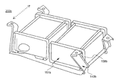
- FIG. 2 is a perspective view of a battery pack according to an embodiment of the present invention.
- FIG. 3 is a perspective view of a battery pack according to another embodiment of the present invention.
- FIG. 4 is a perspective view of a battery pack structure in which an end plate is mounted to each of the battery modules in the battery pack structure of FIG. 2 for comparison purposes of the present invention
- 5 and 6 are perspective views illustrating deformation amounts when an external force is applied to the battery packs of FIGS. 2 and 4 in left and right directions;
- FIGS. 7 and 8 are perspective views illustrating deformation amounts when an external force is applied to the battery pack of FIGS. 2 and 4 in the front and rear directions;
- FIGS. 9 and 10 are perspective views illustrating deformation amounts when an external force is applied to the battery packs of FIGS. 2 and 4 in the vertical direction.
- FIG. 2 is a perspective view schematically showing a battery pack according to an embodiment of the present invention.
- the battery pack 200 includes a battery module array 122, a base plate 130, and a pair of main members 140 in which battery modules 110 and 120 are arranged in two rows of side surfaces. And an end plate 150 and a supporting bar 160.
- the battery modules 110 and 120 are vertically stacked on the upper part of the base plate 130, and the end plate 150 of the battery module assembly 122 is fixed to the base plate 130 at a lower end thereof. It is in close contact with the front and back.
- the main member 140 is positioned on the front and rear surfaces of the battery module assembly 122 to support the load of the battery modules 110 and 120, and both ends thereof are fastened to an external device (not shown).
- the main member 140 has a U-shaped frame structure surrounding both sides and the lower surface of the battery module array 122, the upper end of the main member 140 is bent to the outside and the fastener 142 in the bent portion ) Is formed so that the battery pack 200 can be easily mounted to an external device.
- the supporting bar 160 connects the upper both sides of the end plates 150 to interconnect and support the pair of end plates 150.
- the end plate 150 is integral with the front surface of the battery module assembly 122 and is formed in a planar rectangle, thereby minimizing deformation of the battery pack 200 against vibration in the vertical direction.
- the end plate 150 includes a main body portion 152 contacting the battery module arrangement 122, a top wall 154, a bottom wall 156, protruding outward from an outer circumferential surface of the main body portion 152, and And a pair of sidewalls 158.
- the bottom wall 156 of the end plate 150 is joined to the bottom of the base plate 130 and the main member 140 by four-point welding 151, and the side wall 158 of the end plate 150 is main The side portion of the member 140 and the three-point welding 153 is coupled.
- the bottom wall 156 of the end plate 150 may have a structure in which the bottom wall 156 of the end plate 150 and the bottom end of the main member 140 are coupled by bolting (not shown).
- the side wall 158 of the end plate 150 may also be a structure that is coupled to the side portion of the main member 140 by bolting (not shown).
- the top wall 154 of the end plate 150 protrudes upwards to a size of 10% of the height H of the battery module assembly 122 with respect to the top surface of the battery module assembly 122, thereby supporting The bar 160 is easily mounted on both sides of the top 155 of the end plate 150.
- the battery module 110 is configured by stacking vertically stacked unit modules in which plate-shaped battery cells in which an electrode assembly is embedded in a laminate sheet battery case.
- FIG. 3 is a perspective view schematically showing a battery pack according to another embodiment of the present invention.
- the battery pack 200a of FIG. Since the structure of the battery pack 200 is the same as the detailed description thereof will be omitted.
- FIG. 4 is a perspective view schematically illustrating a structure in which an end plate is mounted on each of the battery modules in the battery pack structure of FIG. 2, for comparison purposes.
- the end plates 150b and 151b are formed to have sizes corresponding to the front and rear surfaces of the battery modules 110b and 120b, and sidewalls of the end plates 150b and 151b are formed. It is the same as the battery pack structure of FIG. 2 except that it is not welded to the side surface of the main member 140b.
- 5 and 6 are perspective views schematically showing the deformation amount when the external force is applied to the battery pack of FIGS. 2 and 4 in the left and right directions.
- 5 and 6 and the structures of FIGS. 7 to 10 to be described later are results of simulation of deformation when an external force is applied to the battery pack.
- the battery pack 200 of FIG. 2 is less deformed in the main member 140 even when an external force is applied in the left and right directions (arrows) of the battery pack, but the battery pack 200b of FIG. It can be seen that the member 140 is greatly deformed in the direction in which the external force is applied and is greatly spaced in the left and right directions from the side wall 158b of the end plate 151b.
- FIGS. 7 and 8 are perspective views schematically showing the amount of deformation when the external force is applied to the battery pack of FIGS. 2 and 4 in the front and rear directions.
- the battery pack 200 of FIG. 2 is less deformed in the main member 140 even when an external force is applied in the front-rear direction (arrow) of the battery pack, but the battery pack 200b of FIG. It can be seen that the member 140 is greatly deformed in the direction in which the external force is applied and is greatly spaced in the front-rear direction from the side wall 18b of the end plate 151b.
- FIGS. 9 and 10 are perspective views schematically showing the deformation amount when the external force is applied to the battery pack of FIGS. 2 and 4 in the vertical direction.
- the battery pack 200 of FIG. 2 is less deformed in the main member 140 even when an external force is applied in the vertical direction (arrow) of the battery pack, but the battery pack 200b of FIG. Since the member 140 is greatly deformed in the direction of applying the external force, it can be seen that the middle portion 142b of the main member 140 is largely curved downward.
- the battery pack structure of FIG. 2 is integrally formed with the end plate and the side wall of the end plate is welded to the side surface of the main member, so that the battery pack structure of FIG. It can be seen that even in high vibration structural stability is greatly improved.
- the weight of the battery pack is 30 Kg or more, and the structure of the main member vibrates vertically. If it is vulnerable to, it can be practically applied to a vehicle vulnerable to vibration up and down.
- the battery pack according to the present invention since the battery modules are arranged in two rows or more sides, compared with the conventional battery pack structure consisting of one battery module can provide a high output large capacity electric capacity, the end By forming the plate in a specific structure that is integrally formed with a size corresponding to the front or rear surface of the battery module assembly, it is possible to minimize the deformation of the battery pack to the vibration in the vertical direction.
- the battery pack by forming a part of the structure of the battery pack by using some form of the vehicle it can be stably mounted on the vehicle, it can minimize the volume occupied in the vehicle.
Abstract
Description

Claims (16)
- 전지셀들 자체 또는 둘 또는 그 이상의 전지셀들이 내장된 단위모듈들을 수직으로 세워 적층한 구조의 전지모듈이 2열 이상 측면으로 배열되어 있는 전지모듈 배열체; A battery module array in which battery modules themselves or two or more battery cells are stacked vertically with unit modules in which two or more battery cells are built and stacked in two or more rows;전지모듈들이 수직으로 세워져 적층되는 베이스 플레이트; A base plate on which the battery modules are vertically stacked;전지모듈들의 하중을 지지하기 위해 전지모듈 배열체의 전면과 후면에 각각 위치하고 양 단부가 외부 디바이스에 체결되는 구조로 이루어진 한 쌍의 메인 멤버; A pair of main members each of which is disposed on the front and rear surfaces of the battery module assembly to support the loads of the battery modules, the both ends of which are fastened to an external device;상기 베이스 플레이트에 하단이 고정된 상태로 전지모듈 배열체의 전면과 후면에 밀착되는 한 쌍의 엔드 플레이트; 및 A pair of end plates in close contact with the front and rear surfaces of the battery module assembly with the bottom fixed to the base plate; And상기 엔드 플레이트들을 상호 연결하여 지지하기 위해 엔드 플레이트들의 상부 또는 측면 양측을 연결하고 있는 서포팅 바; A supporting bar connecting the upper or side sides of the end plates to mutually support the end plates;를 포함하는 것으로 구성되어 있고,Consists of including상기 엔드 플레이트는, 상하 방향으로의 진동에 대한 전지팩의 변형을 최소화할 수 있도록, 전지모듈 배열체의 전면 또는 후면에 대응하는 크기로서 일체형으로 형성되어 있는 전지팩. The end plate, the battery pack is formed integrally with the size corresponding to the front or rear of the battery module assembly so as to minimize the deformation of the battery pack to the vibration in the vertical direction.
- 제 1 항에 있어서, 상기 전지셀은 판상형 전지셀인 것을 특징으로 하는 전지팩. The method of claim 1, wherein the battery cell is a battery pack, characterized in that the plate-shaped battery cell.
- 제 2 항에 있어서, 상기 전지셀은 라미네이트 전지케이스에 전극조립체가 내장되어 있는 구조로 이루어진 것을 특징으로 하는 전지팩. The battery pack according to claim 2, wherein the battery cell has a structure in which an electrode assembly is built in a laminate battery case.
- 제 1 항에 있어서, 상기 메인 멤버는 전지모듈 배열체의 양측면과 하면을 감싸는 U자형 프레임 구조로 이루어진 것을 특징으로 하는 전지팩. The battery pack as claimed in claim 1, wherein the main member has a U-shaped frame structure surrounding both side surfaces and a bottom surface of the battery module assembly.
- 제 4 항에 있어서, 상기 메인 멤버의 상단부는 외부 디바이스와 장착을 용이하게 할 수 있도록 외측으로 절곡되어 있고 절곡된 부위에는 체결구가 형성되어 있는 것을 특징으로 하는 전지팩. The battery pack according to claim 4, wherein the upper end of the main member is bent outwardly to facilitate mounting with an external device, and a fastener is formed at the bent portion.
- 제 1 항에 있어서, 상기 엔드 플레이트는, 상기 전지모듈 배열체에 접하는 본체부와, 상기 본체부의 외주면으로부터 외측 방향으로 돌출된 형상의 상단벽, 하단벽, 및 한 쌍의 측벽을 포함하고 있는 것을 특징으로 하는 전지팩. The method of claim 1, wherein the end plate includes a main body portion in contact with the battery module assembly, an upper end wall, a bottom wall, and a pair of sidewalls protruding outwardly from an outer circumferential surface of the main body portion. A battery pack characterized by the above.
- 제 6 항에 있어서, 상기 엔드 플레이트의 하단벽은 베이스 플레이트 및 메인 멤버의 하단부와 용접 또는 볼팅에 의해 결합되어 있는 것을 특징으로 하는 전지팩. The battery pack according to claim 6, wherein the bottom wall of the end plate is coupled to the bottom plate of the base plate and the main member by welding or bolting.
- 제 7 항에 있어서, 용접점 또는 볼팅 부위의 수는 4 점 이상인 것을 특징으로 하는 전지팩. 8. The battery pack according to claim 7, wherein the number of welding spots or bolting sites is at least four.
- 제 6 항에 있어서, 상기 엔드 플레이트의 측벽은 메인 멤버의 측면부와 용접 또는 볼팅에 의해 결합되어 있는 것을 특징으로 하는 전지팩. The battery pack according to claim 6, wherein the side wall of the end plate is coupled to the side surface of the main member by welding or bolting.
- 제 9 항에 있어서, 용접점 또는 볼팅 부위의 수는 1 점 이상인 것을 특징으로 하는 전지팩. The battery pack according to claim 9, wherein the number of welding spots or bolting sites is one or more.
- 제 6 항에 있어서, 상기 엔드 플레이트의 상단벽은 서포팅 바를 장착하기 위해 전지모듈 배열체의 상단면을 기준으로 상향 돌출되어 있는 것을 특징으로 하는 전지팩. The battery pack as claimed in claim 6, wherein the top wall of the end plate protrudes upward from the top surface of the battery module assembly to mount the supporting bar.
- 제 11 항에 있어서, 상기 상향 돌출된 높이는 전지모듈 배열체의 높이를 기준으로 2 내지 20%의 크기로 이루어진 것을 특징으로 하는 전지팩. The battery pack as claimed in claim 11, wherein the height of the upward protrusion is 2 to 20% based on the height of the battery module array.
- 제 1 항에 있어서, 상기 엔드 플레이트는 평면상 직사각형으로 이루어진 것을 특징으로 하는 전지팩. The battery pack as claimed in claim 1, wherein the end plate has a planar rectangle.
- 제 1 항에 있어서, 상기 엔드 플레이트의 상부에는 서포팅 바를 장착하기 위한 관통홀들이 형성되어 있는 것을 특징으로 하는 전지팩. The battery pack as claimed in claim 1, wherein through-holes for mounting a supporting bar are formed in an upper portion of the end plate.
- 제 1 항에 따른 전지팩을 전원으로 사용하는 것을 특징으로 하는 전기자동차, 하이브리드 전기자동차, 또는 플러그-인 하이브리드 전기자동차. An electric vehicle, a hybrid electric vehicle, or a plug-in hybrid electric vehicle, using the battery pack according to claim 1 as a power source.
- 제 15 항에 있어서, 상기 전지팩은 차량의 트렁크 하단부 또는 차량의 리어 시트와 트렁크 사이에 장착되는 것을 특징으로 하는 전기자동차, 하이브리드 전기자동차, 또는 플러그-인 하이브리드 전기자동차. The electric vehicle, the hybrid electric vehicle, or the plug-in hybrid electric vehicle, characterized in that the battery pack is mounted between the trunk bottom of the vehicle or between the rear seat and the trunk of the vehicle.
Priority Applications (5)
| Application Number | Priority Date | Filing Date | Title |
|---|---|---|---|
| US13/574,256 US8728648B2 (en) | 2010-01-27 | 2011-01-26 | Battery pack of excellent structural stability |
| EP11737276.3A EP2530765B1 (en) | 2010-01-27 | 2011-01-26 | Battery pack having outstanding structural stability |
| JP2012551084A JP5593400B2 (en) | 2010-01-27 | 2011-01-26 | Battery pack with excellent structural stability |
| CN201180006884.6A CN102714292B (en) | 2010-01-27 | 2011-01-26 | Battery pack having outstanding structural stability |
| US13/960,502 US8808896B2 (en) | 2010-01-27 | 2013-08-06 | Battery pack of excellent structural stability |
Applications Claiming Priority (2)
| Application Number | Priority Date | Filing Date | Title |
|---|---|---|---|
| KR10-2010-0007611 | 2010-01-27 | ||
| KR1020100007611A KR101230350B1 (en) | 2010-01-27 | 2010-01-27 | Battery Pack of Excellent Structural Stability |
Related Child Applications (2)
| Application Number | Title | Priority Date | Filing Date |
|---|---|---|---|
| US13/574,256 A-371-Of-International US8728648B2 (en) | 2010-01-27 | 2011-01-26 | Battery pack of excellent structural stability |
| US13/960,502 Continuation US8808896B2 (en) | 2010-01-27 | 2013-08-06 | Battery pack of excellent structural stability |
Publications (2)
| Publication Number | Publication Date |
|---|---|
| WO2011093637A2 true WO2011093637A2 (en) | 2011-08-04 |
| WO2011093637A3 WO2011093637A3 (en) | 2011-11-10 |
Family
ID=44319976
Family Applications (1)
| Application Number | Title | Priority Date | Filing Date |
|---|---|---|---|
| PCT/KR2011/000535 WO2011093637A2 (en) | 2010-01-27 | 2011-01-26 | Battery pack having outstanding structural stability |
Country Status (6)
| Country | Link |
|---|---|
| US (2) | US8728648B2 (en) |
| EP (1) | EP2530765B1 (en) |
| JP (1) | JP5593400B2 (en) |
| KR (1) | KR101230350B1 (en) |
| CN (1) | CN102714292B (en) |
| WO (1) | WO2011093637A2 (en) |
Families Citing this family (63)
| Publication number | Priority date | Publication date | Assignee | Title |
|---|---|---|---|---|
| KR101224496B1 (en) * | 2010-02-04 | 2013-01-21 | 주식회사 엘지화학 | Battery Pack Having Reinforcement Member |
| KR101231111B1 (en) * | 2010-10-27 | 2013-02-07 | 주식회사 엘지화학 | Battery Pack of Improved Durability |
| KR20130066460A (en) * | 2011-12-12 | 2013-06-20 | 삼성에스디아이 주식회사 | Secondary battery module |
| KR101488411B1 (en) * | 2012-01-02 | 2015-02-03 | 주식회사 엘지화학 | Battery Pack Including Connecting member, Side Supporting Member and Bottom Supporting Member |
| CN103178217B (en) * | 2013-03-19 | 2015-04-15 | 永济新时速电机电器有限责任公司 | Power supply device of track inspection car |
| KR102351838B1 (en) | 2013-08-05 | 2022-01-18 | 트위스트 바이오사이언스 코포레이션 | De novo synthesized gene libraries |
| US9321337B2 (en) * | 2013-12-23 | 2016-04-26 | Ford Global Technologies, Llc | Battery array rail assembly with tie bracket |
| JP5846193B2 (en) * | 2013-12-25 | 2016-01-20 | トヨタ自動車株式会社 | Battery mounting structure for vehicles |
| US20160315299A1 (en) * | 2013-12-26 | 2016-10-27 | Panasonic Intellectual Property Management Co., Ltd. | Battery module |
| US10377323B2 (en) * | 2014-05-16 | 2019-08-13 | Ethel M Lennan | Three-axis shackle assembly for mounted object and method for using same |
| US9608245B2 (en) | 2014-09-30 | 2017-03-28 | Johnson Controls Technology Company | System for providing structural integrity of a battery module |
| WO2016126987A1 (en) | 2015-02-04 | 2016-08-11 | Twist Bioscience Corporation | Compositions and methods for synthetic gene assembly |
| WO2016126882A1 (en) | 2015-02-04 | 2016-08-11 | Twist Bioscience Corporation | Methods and devices for de novo oligonucleic acid assembly |
| US9656540B2 (en) * | 2015-03-09 | 2017-05-23 | Michael P. Held | Method for increasing travel time for open-air carts without requiring battery charging |
| US9981239B2 (en) | 2015-04-21 | 2018-05-29 | Twist Bioscience Corporation | Devices and methods for oligonucleic acid library synthesis |
| JP6540355B2 (en) * | 2015-08-10 | 2019-07-10 | 株式会社豊田自動織機 | Battery pack |
| DE102015216029A1 (en) * | 2015-08-21 | 2017-02-23 | Robert Bosch Gmbh | battery Pack |
| CA2998169A1 (en) | 2015-09-18 | 2017-03-23 | Twist Bioscience Corporation | Oligonucleic acid variant libraries and synthesis thereof |
| WO2017053450A1 (en) | 2015-09-22 | 2017-03-30 | Twist Bioscience Corporation | Flexible substrates for nucleic acid synthesis |
| CA3006867A1 (en) | 2015-12-01 | 2017-06-08 | Twist Bioscience Corporation | Functionalized surfaces and preparation thereof |
| JP6493200B2 (en) * | 2015-12-24 | 2019-04-03 | トヨタ自動車株式会社 | Battery pack for vehicle installation |
| US10632857B2 (en) | 2016-08-17 | 2020-04-28 | Shape Corp. | Battery support and protection structure for a vehicle |
| SG11201901563UA (en) | 2016-08-22 | 2019-03-28 | Twist Bioscience Corp | De novo synthesized nucleic acid libraries |
| WO2018057526A2 (en) | 2016-09-21 | 2018-03-29 | Twist Bioscience Corporation | Nucleic acid based data storage |
| CN106394217A (en) * | 2016-10-28 | 2017-02-15 | 东风商用车有限公司 | Power storage battery support assembly |
| CN106298362B (en) * | 2016-10-28 | 2019-01-04 | 佛山市通宝华龙控制器有限公司 | A kind of Kick type temperature controller of double structure |
| KR102249896B1 (en) | 2016-11-08 | 2021-05-07 | 삼성에스디아이 주식회사 | Rechargeable battery module and pack |
| CN106374072A (en) * | 2016-11-10 | 2017-02-01 | 徐州徐工汽车制造有限公司 | Electric vehicle battery fixing support |
| CN106394682A (en) * | 2016-11-11 | 2017-02-15 | 重庆小康工业集团股份有限公司 | Battery pack bracket assembly |
| DE102016223229A1 (en) | 2016-11-23 | 2018-05-24 | Volkswagen Aktiengesellschaft | Battery assembly and vehicle with such a battery assembly |
| US10431785B2 (en) * | 2016-11-30 | 2019-10-01 | Ford Global Technologies, Llc | Battery pack array frames with integrated fastener housings |
| CA3047128A1 (en) | 2016-12-16 | 2018-06-21 | Twist Bioscience Corporation | Variant libraries of the immunological synapse and synthesis thereof |
| EP3566253B1 (en) | 2017-01-04 | 2022-12-28 | Shape Corp. | Battery support structure for a vehicle |
| DE102017100685A1 (en) * | 2017-01-16 | 2018-07-19 | Dr. Ing. H.C. F. Porsche Aktiengesellschaft | Energy supply system for a motor vehicle |
| CN110892485B (en) | 2017-02-22 | 2024-03-22 | 特韦斯特生物科学公司 | Nucleic acid-based data storage |
| CN110913865A (en) | 2017-03-15 | 2020-03-24 | 特韦斯特生物科学公司 | Library of variants of immune synapses and synthesis thereof |
| WO2018213475A1 (en) | 2017-05-16 | 2018-11-22 | Shape Corp. | Polarized battery tray for a vehicle |
| US11211656B2 (en) | 2017-05-16 | 2021-12-28 | Shape Corp. | Vehicle battery tray with integrated battery retention and support feature |
| US10886513B2 (en) | 2017-05-16 | 2021-01-05 | Shape Corp. | Vehicle battery tray having tub-based integration |
| WO2018231864A1 (en) | 2017-06-12 | 2018-12-20 | Twist Bioscience Corporation | Methods for seamless nucleic acid assembly |
| US10696965B2 (en) | 2017-06-12 | 2020-06-30 | Twist Bioscience Corporation | Methods for seamless nucleic acid assembly |
| CN111566125A (en) | 2017-09-11 | 2020-08-21 | 特韦斯特生物科学公司 | GPCR binding proteins and synthesis thereof |
| US11088412B2 (en) | 2017-09-13 | 2021-08-10 | Shape Corp. | Vehicle battery tray with tubular peripheral wall |
| WO2019071013A1 (en) | 2017-10-04 | 2019-04-11 | Shape Corp. | Battery tray floor assembly for electric vehicles |
| CN111565834B (en) | 2017-10-20 | 2022-08-26 | 特韦斯特生物科学公司 | Heated nanopores for polynucleotide synthesis |
| AU2019205269A1 (en) | 2018-01-04 | 2020-07-30 | Twist Bioscience Corporation | DNA-based digital information storage |
| JP6962230B2 (en) * | 2018-02-16 | 2021-11-05 | トヨタ自動車株式会社 | Battery pack |
| CN112055898A (en) | 2018-03-01 | 2020-12-08 | 形状集团 | Cooling system integrated with vehicle battery tray |
| KR102249488B1 (en) * | 2018-03-12 | 2021-05-06 | 주식회사 엘지화학 | An energy storage device with a hook structure and an energy storage system comprising the same |
| US11688910B2 (en) | 2018-03-15 | 2023-06-27 | Shape Corp. | Vehicle battery tray having tub-based component |
| JP7059738B2 (en) * | 2018-03-22 | 2022-04-26 | トヨタ自動車株式会社 | Battery pack |
| SG11202011467RA (en) | 2018-05-18 | 2020-12-30 | Twist Bioscience Corp | Polynucleotides, reagents, and methods for nucleic acid hybridization |
| DE102018209186A1 (en) * | 2018-06-08 | 2019-12-12 | Robert Bosch Gmbh | Battery unit with a plurality of battery cells and use of such a battery unit |
| JP7067334B2 (en) * | 2018-07-18 | 2022-05-16 | トヨタ自動車株式会社 | Vehicle rear structure |
| KR101981771B1 (en) * | 2018-12-18 | 2019-05-27 | 이국철 | Uninterruptible Power Supply |
| KR101981765B1 (en) * | 2018-12-18 | 2019-05-27 | 이국철 | Uninterruptible Power Supply |
| EP3930753A4 (en) | 2019-02-26 | 2023-03-29 | Twist Bioscience Corporation | Variant nucleic acid libraries for glp1 receptor |
| SG11202109283UA (en) | 2019-02-26 | 2021-09-29 | Twist Bioscience Corp | Variant nucleic acid libraries for antibody optimization |
| US11332738B2 (en) | 2019-06-21 | 2022-05-17 | Twist Bioscience Corporation | Barcode-based nucleic acid sequence assembly |
| CN112776653B (en) * | 2019-11-01 | 2022-11-15 | 爱驰汽车有限公司 | Battery quick-change system and electric vehicle |
| CN115315847B (en) * | 2020-04-01 | 2023-10-03 | Tvs电机股份有限公司 | battery block |
| DE102020117191A1 (en) * | 2020-06-30 | 2021-12-30 | Audi Aktiengesellschaft | Battery for motor vehicles and motor vehicles and manufacturing processes for this |
| CN113708001B (en) * | 2021-08-30 | 2023-06-09 | 安徽巡鹰新能源集团有限公司 | Series battery pack accommodating mechanism |
Citations (3)
| Publication number | Priority date | Publication date | Assignee | Title |
|---|---|---|---|---|
| KR20060012303A (en) | 2003-05-19 | 2006-02-07 | 쇼와 덴코 가부시키가이샤 | Heat exchanger fin, heat exchanger, condensers, and evaporators |
| KR20060020772A (en) | 2004-09-01 | 2006-03-07 | 엘지전자 주식회사 | Dust and dirt collecting unit for vacuum cleaner |
| KR20060045444A (en) | 2004-04-02 | 2006-05-17 | 소니 가부시끼 가이샤 | Solid-state imaging device and production method thereof |
Family Cites Families (22)
| Publication number | Priority date | Publication date | Assignee | Title |
|---|---|---|---|---|
| JPH05193366A (en) * | 1992-01-22 | 1993-08-03 | Honda Motor Co Ltd | Fixing structure of battery for electric vehicle |
| JPH07186734A (en) * | 1993-12-27 | 1995-07-25 | Honda Motor Co Ltd | Battery box structure of motor-driven vehicle |
| JP2001088563A (en) * | 1999-09-28 | 2001-04-03 | Fuji Heavy Ind Ltd | Battery box mounting structure for electric vehicle |
| JP2002010524A (en) * | 2000-06-28 | 2002-01-11 | Mitsubishi Electric Corp | Uninterruptible power supply unit |
| JP5113319B2 (en) * | 2004-10-29 | 2013-01-09 | 富士重工業株式会社 | Storage cell package structure |
| JP2006236826A (en) * | 2005-02-25 | 2006-09-07 | Toyota Motor Corp | Battery pack |
| JP2006260905A (en) * | 2005-03-16 | 2006-09-28 | Toyota Motor Corp | Battery pack structure |
| DE102005013172A1 (en) * | 2005-03-22 | 2006-09-28 | Daimlerchrysler Ag | vehicle battery |
| KR100861713B1 (en) | 2006-02-09 | 2008-10-06 | 주식회사 엘지화학 | Battery Module |
| KR100948002B1 (en) | 2006-03-06 | 2010-03-18 | 주식회사 엘지화학 | Middle or Large-sized Battery Module |
| KR100870457B1 (en) | 2006-05-22 | 2008-11-25 | 주식회사 엘지화학 | Battery Module |
| KR101217459B1 (en) * | 2006-09-25 | 2013-01-02 | 주식회사 엘지화학 | battery module assembly |
| JP2008282582A (en) * | 2007-05-08 | 2008-11-20 | Sanyo Electric Co Ltd | Battery pack |
| KR101141057B1 (en) * | 2007-06-28 | 2012-05-03 | 주식회사 엘지화학 | Middle or Large-sized Battery Pack |
| JP5091060B2 (en) * | 2007-11-21 | 2012-12-05 | 本田技研工業株式会社 | Vehicle power supply |
| JP2009238643A (en) * | 2008-03-27 | 2009-10-15 | Sanyo Electric Co Ltd | Battery block for vehicle |
| JP2009272169A (en) * | 2008-05-08 | 2009-11-19 | Toyota Motor Corp | Power storage device |
| JP5340659B2 (en) * | 2008-07-07 | 2013-11-13 | 三洋電機株式会社 | Battery pack for vehicles |
| JP5414387B2 (en) * | 2009-06-29 | 2014-02-12 | アイシン軽金属株式会社 | Vehicle-mounted frame structure for vehicle battery module |
| US8871379B2 (en) * | 2009-10-30 | 2014-10-28 | Greatbatch Ltd. | Screen-less anode design concepts for low cost lithium electrochemical cells for use in implantable medical device applications |
| KR101084222B1 (en) * | 2009-11-03 | 2011-11-17 | 에스비리모티브 주식회사 | Battery module providing improved base plate |
| KR101224496B1 (en) * | 2010-02-04 | 2013-01-21 | 주식회사 엘지화학 | Battery Pack Having Reinforcement Member |
-
2010
- 2010-01-27 KR KR1020100007611A patent/KR101230350B1/en active IP Right Grant
-
2011
- 2011-01-26 CN CN201180006884.6A patent/CN102714292B/en active Active
- 2011-01-26 US US13/574,256 patent/US8728648B2/en active Active
- 2011-01-26 JP JP2012551084A patent/JP5593400B2/en active Active
- 2011-01-26 WO PCT/KR2011/000535 patent/WO2011093637A2/en active Application Filing
- 2011-01-26 EP EP11737276.3A patent/EP2530765B1/en active Active
-
2013
- 2013-08-06 US US13/960,502 patent/US8808896B2/en active Active
Patent Citations (3)
| Publication number | Priority date | Publication date | Assignee | Title |
|---|---|---|---|---|
| KR20060012303A (en) | 2003-05-19 | 2006-02-07 | 쇼와 덴코 가부시키가이샤 | Heat exchanger fin, heat exchanger, condensers, and evaporators |
| KR20060045444A (en) | 2004-04-02 | 2006-05-17 | 소니 가부시끼 가이샤 | Solid-state imaging device and production method thereof |
| KR20060020772A (en) | 2004-09-01 | 2006-03-07 | 엘지전자 주식회사 | Dust and dirt collecting unit for vacuum cleaner |
Non-Patent Citations (1)
| Title |
|---|
| See also references of EP2530765A4 |
Also Published As
| Publication number | Publication date |
|---|---|
| JP2013518386A (en) | 2013-05-20 |
| KR101230350B1 (en) | 2013-02-06 |
| JP5593400B2 (en) | 2014-09-24 |
| US8808896B2 (en) | 2014-08-19 |
| CN102714292A (en) | 2012-10-03 |
| WO2011093637A3 (en) | 2011-11-10 |
| EP2530765A2 (en) | 2012-12-05 |
| EP2530765A4 (en) | 2013-07-03 |
| CN102714292B (en) | 2015-04-08 |
| EP2530765B1 (en) | 2017-09-20 |
| US20130186700A1 (en) | 2013-07-25 |
| US8728648B2 (en) | 2014-05-20 |
| KR20110087938A (en) | 2011-08-03 |
| US20130319777A1 (en) | 2013-12-05 |
Similar Documents
| Publication | Publication Date | Title |
|---|---|---|
| WO2011093637A2 (en) | Battery pack having outstanding structural stability | |
| WO2011096677A2 (en) | Battery pack with a reinforcing member | |
| WO2012157857A2 (en) | Battery pack having excellent structural reliability | |
| WO2012057489A2 (en) | Battery pack having improved durability | |
| WO2011046319A2 (en) | Battery module with superior structural stability | |
| WO2017095003A1 (en) | Battery module comprising cartridge having gripping parts | |
| WO2014171559A1 (en) | Battery module having novel structure and battery pack comprising same | |
| WO2012067360A2 (en) | Battery module having superior structural stability | |
| WO2015186923A1 (en) | Battery module and battery pack comprising same | |
| WO2011099703A2 (en) | Battery module having enhanced welding reliability and medium or large battery pack including same | |
| WO2020262832A1 (en) | Battery pack and device comprising same | |
| WO2013015539A1 (en) | Battery module having improved reliability and mid-to-large battery pack comprising same | |
| WO2019124796A1 (en) | Battery module, and battery pack and vehicle comprising same | |
| WO2012067365A2 (en) | Battery module having enhanced safety | |
| WO2015174714A1 (en) | Battery pack including spacer | |
| WO2015046898A1 (en) | Battery module provided with damping structure and comprising electrode lead | |
| WO2018230819A1 (en) | Battery module, battery pack comprising battery module, and vehicle comprising battery pack | |
| WO2021150006A1 (en) | Battery module, battery rack comprising same battery module, and power storage device | |
| WO2022045591A1 (en) | Large battery module and battery pack including same | |
| WO2018174388A1 (en) | Battery pack | |
| WO2022119182A1 (en) | Battery pack, power storage device and vehicle | |
| WO2017069384A1 (en) | Battery protection structure and battery module comprising same | |
| WO2021235783A1 (en) | Battery module, battery pack comprising same, and vehicle | |
| WO2022154315A1 (en) | Battery pack and device including same | |
| WO2022080909A1 (en) | Battery module and battery pack including same |
Legal Events
| Date | Code | Title | Description |
|---|---|---|---|
| WWE | Wipo information: entry into national phase |
Ref document number: 201180006884.6 Country of ref document: CN |
|
| 121 | Ep: the epo has been informed by wipo that ep was designated in this application |
Ref document number: 11737276 Country of ref document: EP Kind code of ref document: A1 |
|
| REEP | Request for entry into the european phase |
Ref document number: 2011737276 Country of ref document: EP |
|
| WWE | Wipo information: entry into national phase |
Ref document number: 2012551084 Country of ref document: JP Ref document number: 2011737276 Country of ref document: EP |
|
| NENP | Non-entry into the national phase |
Ref country code: DE |
|
| WWE | Wipo information: entry into national phase |
Ref document number: 13574256 Country of ref document: US |