WO2011083555A1 - Image processing device, image generating system, method, and program - Google Patents

Image processing device, image generating system, method, and program Download PDF

Info

Publication number
WO2011083555A1
WO2011083555A1 PCT/JP2010/007578 JP2010007578W WO2011083555A1 WO 2011083555 A1 WO2011083555 A1 WO 2011083555A1 JP 2010007578 W JP2010007578 W JP 2010007578W WO 2011083555 A1 WO2011083555 A1 WO 2011083555A1
Authority
WO
WIPO (PCT)
Prior art keywords
image
moving image
pixel
condition
new
Prior art date
Application number
PCT/JP2010/007578
Other languages
French (fr)
Japanese (ja)
Inventor
今川 太郎
吾妻 健夫
Original Assignee
パナソニック株式会社
Priority date (The priority date is an assumption and is not a legal conclusion. Google has not performed a legal analysis and makes no representation as to the accuracy of the date listed.)
Filing date
Publication date
Application filed by パナソニック株式会社 filed Critical パナソニック株式会社
Priority to CN201080023498.3A priority Critical patent/CN102450019B/en
Priority to JP2011525338A priority patent/JP4806476B2/en
Priority to EP10842075.3A priority patent/EP2523459B1/en
Publication of WO2011083555A1 publication Critical patent/WO2011083555A1/en
Priority to US13/239,653 priority patent/US8471927B2/en

Links

Images

Classifications

    • GPHYSICS
    • G06COMPUTING; CALCULATING OR COUNTING
    • G06TIMAGE DATA PROCESSING OR GENERATION, IN GENERAL
    • G06T3/00Geometric image transformation in the plane of the image
    • G06T3/40Scaling the whole image or part thereof
    • G06T3/4053Super resolution, i.e. output image resolution higher than sensor resolution
    • G06T3/4061Super resolution, i.e. output image resolution higher than sensor resolution by injecting details from a different spectral band
    • GPHYSICS
    • G06COMPUTING; CALCULATING OR COUNTING
    • G06TIMAGE DATA PROCESSING OR GENERATION, IN GENERAL
    • G06T5/00Image enhancement or restoration
    • G06T5/50Image enhancement or restoration by the use of more than one image, e.g. averaging, subtraction
    • G06T5/94
    • HELECTRICITY
    • H04ELECTRIC COMMUNICATION TECHNIQUE
    • H04NPICTORIAL COMMUNICATION, e.g. TELEVISION
    • H04N23/00Cameras or camera modules comprising electronic image sensors; Control thereof
    • H04N23/95Computational photography systems, e.g. light-field imaging systems
    • H04N23/951Computational photography systems, e.g. light-field imaging systems by using two or more images to influence resolution, frame rate or aspect ratio
    • GPHYSICS
    • G06COMPUTING; CALCULATING OR COUNTING
    • G06TIMAGE DATA PROCESSING OR GENERATION, IN GENERAL
    • G06T2207/00Indexing scheme for image analysis or image enhancement
    • G06T2207/10Image acquisition modality
    • G06T2207/10016Video; Image sequence
    • GPHYSICS
    • G06COMPUTING; CALCULATING OR COUNTING
    • G06TIMAGE DATA PROCESSING OR GENERATION, IN GENERAL
    • G06T2207/00Indexing scheme for image analysis or image enhancement
    • G06T2207/10Image acquisition modality
    • G06T2207/10141Special mode during image acquisition
    • G06T2207/10144Varying exposure
    • GPHYSICS
    • G06COMPUTING; CALCULATING OR COUNTING
    • G06TIMAGE DATA PROCESSING OR GENERATION, IN GENERAL
    • G06T2207/00Indexing scheme for image analysis or image enhancement
    • G06T2207/20Special algorithmic details
    • G06T2207/20172Image enhancement details
    • G06T2207/20208High dynamic range [HDR] image processing

Definitions

  • the present invention relates to image processing for generating a moving image, and in particular, image processing for generating a new moving image representing a target from a plurality of moving images obtained by shooting the same target under different shooting conditions. About.
  • a method of brightening a photographed image with insufficient light quantity by electrically amplifying the signal after receiving light can be considered.
  • this method also amplifies noise at the same time and does not improve the S / N ratio.
  • a method of increasing the amount of received light by extending the exposure time can be considered.
  • motion blur occurs due to the movement of the subject, and a clear image cannot be taken.
  • an optical system such as a lens is enlarged in order to increase the amount of received light, there arises a problem of an increase in cost and a decrease in portability.
  • FIG. 26 is a flowchart showing a processing procedure of the conventional image generating apparatus described in Patent Document 1.
  • step A1 of FIG. 26 a high-speed low-resolution moving image obtained by photographing the same event and a low-speed high-resolution moving image with long exposure are acquired.
  • step A2 an image is generated by reducing an error between the total of new moving image frames during the exposure period of the low-speed high-resolution moving image and the low-speed high-resolution moving image.
  • the generated image is output.
  • the present invention has been made to solve the conventional problems, and its purpose is to generate saturation when obtaining a high-resolution and high-frame-rate image from an image that has been captured with a sufficient exposure amount by long-time exposure or the like. Even in this case, it is to obtain a high-quality image.
  • the image generation apparatus is a new video representing a subject from a first moving image that is a moving image of the first color component of the subject and a second moving image that is a moving image of the second color component of the subject.
  • An image generation device for generating a moving image the image acquisition unit acquiring the first moving image and the second moving image having different resolution and frame rate or exposure time, and the first moving image
  • a light amount determination unit that determines whether or not each pixel is saturated or blacked based on a pixel value in each pixel in each frame image of the image and the second moving image; and the first moving image and the second moving image From a moving image, a new frame rate that is equal to or higher than the frame rate of the first moving image and the second moving image, and the resolution of each frame image is equal to or higher than the resolution of the first moving image and the second moving image.
  • An image processing unit that generates an image, and the pixels of the first moving image and the second moving image that are acquired for pixels that the light amount determination unit has not determined to be saturated or blackened Generating a new moving image satisfying a first condition indicating that an error between a value and a sum of pixel values of a frame image of the new moving image corresponding in time and space to the pixel is smaller than a predetermined value, An image processing unit that generates a new moving image that does not satisfy the first condition is provided for a pixel that is determined to be saturated or blackened by the light amount determination unit.
  • the first color component may be at least one of red and blue, and the second color component may be green.
  • the light amount determination unit may determine that the light amount in each pixel is saturated when the light amount is equal to or greater than a predetermined saturation value.
  • the light amount determination unit may determine that the amount of light in each pixel is blacked out when the amount of light in each pixel is equal to or less than a predetermined blacked out value.
  • the saturation value may be set for each of the first color component and the second color component.
  • the blackout value may be set for each of the first color component and the second color component.
  • the image processing unit When the light amount determination unit determines that the pixel is saturated, the image processing unit reduces the pixel value of the pixel, and when the light amount determination unit determines that the pixel is blackened The image processing unit may increase the pixel value of the pixel.
  • the image generation apparatus further includes a second condition setting unit that sets a second condition relating to spatiotemporal continuity representing that the colors of temporally and spatially adjacent pixels in a new moving image to be generated should be continuous.
  • the image processing unit may generate a new moving image that satisfies the second condition.
  • the second condition setting unit may set the second condition relating to the spatiotemporal continuity and the second condition individually for the signal intensity and color of the pixel.
  • the second condition setting unit determines a weight to be applied at a pixel position of each pixel of the new moving image with respect to the set second condition, and the second condition setting unit is acquired
  • the second condition may be set by reducing the weight of the position where the spatial differential value of the first moving image and the second moving image is large.
  • the second condition setting unit may set the second condition by setting the spatiotemporal continuity of the color of the pixel to be greater than the spatiotemporal continuity of the signal intensity of the pixel.
  • the second condition setting unit is configured to select a second condition related to the spatiotemporal continuity according to a direction selected according to the magnitude of dispersion of pixel values in the color space of the acquired image, and orthogonal to the direction. It may be set for each direction.
  • the second condition setting unit determines the second condition at the pixel position of the pixel determined to be saturated or blacked out by the light amount determination unit, and the pixel position of the pixel not determined to be saturated or blacked out You may set stronger than the said 2nd condition in.
  • the image generation device further includes a light amount control unit that adjusts an exposure amount of an imaging device that captures the first moving image and the second moving image, and each of the first moving image and the second moving image.
  • a light amount control unit that adjusts an exposure amount of an imaging device that captures the first moving image and the second moving image, and each of the first moving image and the second moving image.
  • the light amount control unit reduces the exposure amount of the imaging device when capturing a moving image of at least one color component. May be.
  • the image generation apparatus determines that pixel values along a motion vector in a new moving image to be generated should match based on a motion detection unit that detects the acquired motion of the image and the detection result of the motion.
  • a third condition setting unit that sets a third condition to be expressed, and the image processing unit may generate a new moving image that satisfies the third condition.
  • the third condition setting unit sets the third condition for the pixel position determined to be saturated or blacked out by the light amount determining unit as to the third position at the pixel position not determined to be saturated or blacked out. You may set more strongly than conditions.
  • the image generation system according to claim 1, wherein the image generation system according to the present invention generates the new moving image using an imaging device, a storage device that records an image captured by the imaging device, and an image of the storage device. And a generating device.
  • Another image generation system includes the above-described image generation device and a display device that displays the new moving image generated by the image generation device.
  • the image generation apparatus may acquire each signal of the first image and the second image via at least one of a memory card, an antenna, and a network.
  • the method according to the present invention provides a new moving image representing a subject from a first moving image that is a moving image of the first color component of the subject and a second moving image that is a moving image of the second color component of the subject.
  • the pixel values of the acquired first moving image and the second moving image, and the pixels A new moving image that satisfies the first condition indicating that an error from the sum of the pixel values of the frame image of the new moving image corresponding in time and space is smaller than a predetermined value is generated and saturated in the step of determining Alternatively, a step of generating a new image for generating a new moving image that does not satisfy the first condition is included for pixels determined to be blackened.
  • a computer program provides a new moving image representing a subject from a first moving image that is a moving image of the first color component of the subject and a second moving image that is a moving image of the second color component of the subject.
  • a computer program executed by a computer of an image generating apparatus for generating an image, wherein the computer program is different from the computer in the first moving image and the resolution, the frame rate, or the exposure time.
  • the step of obtaining the second moving image and determining whether each pixel is saturated or blacked based on a pixel value in each pixel in each frame image of the first moving image and the second moving image A frame rate of the first moving image and the second moving image from the first moving image and the second moving image.
  • a moving image is generated by allowing an error between the sum of a plurality of frames of a generated moving image and a still image for an image region saturated by long-time exposure or the like. Thereby, it is possible to improve the image quality of the moving image generated corresponding to the saturated region.
  • FIG. 1 is a block diagram illustrating a hardware configuration of an image generation system 100 according to Embodiment 1.
  • FIG. It is a functional block diagram which shows the internal structure of the image generation apparatus 30 shown by FIG. 4 is a flowchart illustrating a procedure of processing executed by the image generation device 30.
  • (A) And (b) is a figure which shows the relationship between the high-speed low-resolution moving image acquired by the high-speed image acquisition part 101a, and the low-speed high-resolution moving image acquired by the low-speed image acquisition part 101b. It is a figure which shows the relationship between the exposure timing of a low-speed high-resolution moving image and a high-speed low-resolution moving image.
  • FIG. 1 It is a figure which shows an example of the format of the video signal 210 which has the identification header 210a in which the information of imaging conditions was described, and the moving image data 210b.
  • FIG. 1 (A)-(c) is a figure which shows the structural example of an imaging device.
  • (A) to (c) are pixel values of a high-speed and high-resolution moving image, pixel values of a high-speed and low-resolution moving image acquired by the high-speed image acquisition unit 101a, and low-speed and high-resolution acquired by the low-speed image acquisition unit 101b. It is a figure explaining the relationship with the pixel value of a moving image.
  • (A) And (b) is a figure which shows the time change of imaging
  • (A)-(c) is a figure explaining the relationship between a pixel value and the incident light quantity at the time of imaging.
  • (A) And (b) is a figure showing the pixel arrangement
  • (A) And (b) is a figure showing the example of the image which image
  • (A) to (f) and (g) to (l) are diagrams showing high-speed and low-resolution RB continuous frame images, respectively.
  • (A) to (r) are diagrams showing high-speed and high-resolution RGB images.
  • (A) And (b) is a figure which shows the example of an image when the saturation area
  • positioning as FIG. (A)-(r) is a figure which shows the example of the image produced
  • (A) And (b) is a figure which shows the relationship between the pixel position and pixel value about R and G image.
  • FIG. 10 is a functional block diagram illustrating an internal configuration of an image generation device 30 according to a third embodiment. 14 is a flowchart illustrating a processing procedure of the image generation apparatus 30 according to the third embodiment. It is a figure which shows the specific example of an image generation system which does not have a display apparatus. It is a figure which shows the specific example of the image generation system which does not have an imaging device. 10 is a flowchart showing a processing procedure of a conventional image generating apparatus described in Patent Literature 1.
  • FIG. 1 is a block diagram showing a hardware configuration of an image generation system 100 according to the present embodiment.
  • the image generation system 100 generates a new color moving image with high spatio-temporal resolution from moving images of a plurality of color components obtained by photographing the same object (subject) with different exposure times and different frame rates.
  • an example of generating a high-speed and high-resolution image from a high-speed and low-resolution image and a low-speed and high-resolution image will be described.
  • the image generation system 100 includes an imaging device 10, an image storage device 20, an image generation device 30, and a display device 40.
  • the imaging device 10 is, for example, a camera, which captures a subject under different shooting conditions and obtains moving images with two different types of spatiotemporal resolution.
  • This “moving image” is a high-speed low-resolution moving image (moving image having a relatively high temporal resolution (frame rate) and a relatively low spatial resolution) and a low-speed high-resolution moving image for the same subject. (A moving image having a relatively low temporal resolution and a relatively high spatial resolution).
  • the image storage device 20 is a semiconductor memory, for example, and temporarily stores a moving image captured by the imaging device 10.
  • the image generation device 30 is an image processing circuit (graphic controller) implemented by hardware, for example.
  • the image generating apparatus 30 can be manufactured and / or sold alone.
  • the image generation device 30 is incorporated as a part of the image generation system 100 to read out a moving image stored in the image storage device 20, and a new moving image with improved spatiotemporal resolution from the plurality of read moving images. Is generated.
  • the image generation device 30 is realized by hardware such as a dedicated circuit, but may be realized by a general-purpose processor and software such as an image processing program.
  • the display device 40 is, for example, a liquid crystal display device, and displays a new moving image generated by the image generation device 30.
  • the image storage device 20 and the image generation device 30 may be hardware such as a PC, for example.
  • FIG. 2 is a functional block diagram showing an internal configuration of the image generation apparatus 30 shown in FIG.
  • the image generation apparatus 30 includes an image acquisition unit 101, a motion detection unit 102, an image processing unit 103, a light amount determination unit 104, and an output unit 106.
  • the image acquisition unit 101 acquires moving images having different temporal and spatial resolutions and colors obtained by imaging the same subject.
  • the image acquisition unit 101 includes a high-speed image acquisition unit 101a and a low-speed image acquisition unit 101b.
  • the high-speed image acquisition unit 101a is a moving image of red component (R) and blue component (B) captured at high speed (high frame rate) and low spatial resolution (in this embodiment, for each of these color components). Is referred to as a “high-speed, low-resolution moving image”).
  • the low-speed image acquisition unit 101b is a moving image of a green component (G) obtained by photographing the same subject as the high-speed image acquisition unit 101a at a low speed (low frame rate) and a high spatial resolution (in this embodiment, a green component (G) Is acquired as a “low-speed high-resolution moving image”).
  • the image input to the high-speed image acquisition unit 101a and the image input to the low-speed image acquisition unit 101b are images obtained by photographing the same subject, although the spatio-temporal resolution and color are different.
  • combinations of target colors for capturing high-speed and low spatial resolution moving images and target colors for capturing low-speed and high spatial resolution moving images are examples. If a moving image is captured for each wavelength band of light, in other words, for each color component, the combination is arbitrary. In the present specification, the green component is simply described as “green” or “G”.
  • the motion detection unit 102 includes a motion distribution calculation unit 102a and a reliability distribution calculation unit 102b.
  • the motion detection unit 102 detects the motion of the image in the input image and calculates the reliability of the motion detection, and outputs the result. More specifically, the motion distribution calculation unit 102a performs motion detection on a part of the acquired image (typically a subject) based on the image input to the image acquisition unit 101. Do. Motion detection is finally performed on the entire image of each frame.
  • the reliability distribution calculation unit 102b calculates the reliability of motion detection in the motion distribution calculation unit 102a for the entire image of each frame. A specific description of the reliability distribution calculation unit 102b will be described later.
  • the image processing unit 103 generates a color moving image having a high color resolution and a high frame rate from a plurality of moving images acquired by the image acquiring unit 101.
  • the image processing unit 103 includes a third condition setting unit 103a, a second condition setting unit 103b, a first condition setting unit 103c, and a color image generation unit 103d.
  • the first to third condition setting units set a relationship (condition) that should be satisfied by the acquired moving image and the newly generated moving image.
  • target moving image is a color moving image. However, in the following context, it may refer to an image of one frame constituting a moving image.
  • the third condition setting unit 103a sets a constraint condition for the target moving image using the results of the motion detection and the motion detection reliability acquired from the motion detection unit 102.
  • the second condition setting unit 103b sets a spatial constraint condition for the target moving image.
  • the first condition setting unit 103c sets the relationship between the pixel values of the target moving image and the acquired image (the condition for image degradation of the image acquired from the target moving image).
  • the color image generation unit 103d generates one color moving image from a plurality of moving images having different color components using the constraint condition.
  • “setting” the first condition, the second condition, etc. does not mean that each condition is set independently.
  • an evaluation function J including a plurality of conditions is set, and a moving image that minimizes the evaluation function J is output as a target moving image (new moving image). This is because such a moving image that minimizes the evaluation function J is estimated to satisfy the condition of reducing the value of each constraint condition well.
  • the light quantity determination unit 104 determines whether saturation or blackout has occurred for each pixel value in each frame in the moving image acquired from the image acquisition unit 101.
  • the output unit 106 is an output terminal of the image generation device 30.
  • the output unit 106 is a connector connected to a bus.
  • the output unit 106 outputs the color image data generated by the image processing unit 103 to the outside.
  • the output destination is, for example, the display device 40.
  • the “frame” in the present embodiment includes not only a frame in the progressive method but also an even field and an odd field in the interlace method.
  • FIG. 3 is a flowchart illustrating a procedure of processing executed by the image generation apparatus 30.
  • the image acquisition unit 101 acquires a plurality of moving images having different spatiotemporal resolutions and color components. Specifically, the high-speed image acquisition unit 101a acquires high-speed and low-resolution R and B moving images, and the low-speed image acquisition unit 101b acquires low-speed and high-resolution G moving images for the same subject.
  • the difference in spatial resolution is represented by the size of the image.
  • Frames 211 to 215 have a smaller number of pixels, a lower spatial resolution, and a larger pixel size than frames 201 and 202.
  • the high-speed image acquisition unit 101a has a higher shooting frame rate than the low-speed image acquisition unit 101b.
  • the width in the time direction of the frame 201 and the frame 202 represents the exposure time.
  • the low-speed image acquisition unit 101b captures one frame 201
  • the high-speed image acquisition unit 101a captures 4 frames. Since the image acquired by the low-speed image acquisition unit 101b has a lower frame rate, it can be exposed longer than the image acquired by the high-speed image acquisition unit 101a.
  • the frame 201 of the low-speed and high-resolution moving image is exposed for the interval of four frames of the high-speed and low-resolution moving image of FIG. 4A (b).
  • the shooting timings of the frames acquired by the high-speed image acquisition unit 101a and the frames acquired by the low-speed image acquisition unit 101b are not necessarily required to be simultaneously shot as long as the relative relationship of time is known. That is, the time phase at the imaging timing may be different.
  • the relationship between the exposure timing of the low-speed and high-resolution moving image and the exposure timing of the high-speed and low-resolution moving image may be set as shown in FIG. 4B.
  • the horizontal axis indicates time.
  • the rectangle represents the frame of each pixel, and the width of the rectangle represents the length of the exposure time.
  • the exposure timing of the low-speed and high-resolution moving image is not synchronized with the exposure timing of the high-speed and low-resolution moving image with respect to the input pixels arranged as shown in FIG. 4A (b).
  • Each exposure timing is arbitrary.
  • FIG. 4C shows an example of a format of a video signal 210 having an identification header 210a in which shooting condition information is described and moving image data 210b.
  • the imaging apparatus 10 stores information indicating the shooting conditions in the identification header 210a, and outputs a video signal 210 in which the identification header 210a is added to the captured moving image data 210b.
  • the image acquisition unit 101 of the image generation apparatus 30 receives the video signal 210 and first reads the identification header 210a to acquire information on the shooting conditions. Based on the shooting conditions, the moving image data 210b is acquired. Further, the image processing unit 103 sets conditions to be described later based on the imaging conditions of the identification header 210a.
  • the image capturing condition information stored in the identification header 210a is associated with the exposure time, the frame rate, and the relative time difference (time phase difference) of the pixel exposure timing for each color component and each pixel position. Numerical value or sign.
  • the identification header 210a is digital data. Therefore, values such as exposure time, frame rate, and relative time difference between exposure timings representing photographing conditions may be directly expressed as digital values. Alternatively, the voltage, charge amount, and current value (analog value) in the corresponding image sensor may be rounded to a predetermined number of significant digits, and the value may be expressed as a digital value.
  • the image acquisition unit 101 receives an analog video signal
  • the above information is expressed by analog values such as voltage, charge amount, and current value in the image sensor, or numerical values associated with them. Expressed with a sign.
  • FIG. 5A shows an example of the configuration of an image pickup apparatus using a multi-element method using a dichroic prism or a dichroic mirror.
  • FIG. 5B is an example of a configuration of an imaging apparatus using a multilayer single element method.
  • FIG. 5C shows an example of the configuration of an imaging apparatus using a single-layer single-element method. In each configuration, an image sensor B for blue images, an image sensor G for green images, and an image sensor R for red images are shown.
  • the image sensors R (red) and B (blue) capture red and blue high-speed low-resolution videos
  • the image sensor G (green) captures green low-speed high-resolution videos with a long exposure time. That is, each image sensor captures the same subject by changing the spatial resolution, frame rate, and exposure time for each color.
  • the pixel value of the target high-speed and high-resolution moving image, the pixel value of the high-speed and low-resolution moving image acquired by the high-speed image acquisition unit 101a, and the low-speed The relationship with the pixel value of the low-speed high-resolution moving image acquired by the image acquisition unit 101b will be described.
  • the pixel value is a numerical value determined for each of R, G, and B, and the relationship between pixel values of the same color will be described. This relationship corresponds to the first condition set by the first condition setting unit 103c.
  • the color image generation unit 103d generates an image so that each pixel of the generated high-speed and high-resolution moving image satisfies this condition.
  • FIG. 6A shows a pixel arrangement of each frame of a target high-speed and high-resolution moving image.
  • FIG. 6A shows an arrangement of 3 pixels in the vertical (Y-axis) direction, 3 pixels in the horizontal (X-axis) direction, and 4 frames. That is, a pixel with a spatial resolution of 3 ⁇ 3 and a temporal resolution of 4 frames is shown.
  • FIG. 6B shows a pixel arrangement of a high-speed low-resolution moving image obtained by photographing the same subject as in FIG. 6A from the same viewpoint and the same field of view at the same time.
  • the pixel value of the pixel position (xL, yL, t) of the high-speed and low-resolution moving image is represented as HL (xL, yL, t). Since the number of pixels in the x and y directions is different between the low resolution image and the high resolution image, the x and y coordinate values of the low resolution image are expressed as xL and yL, respectively, and are distinguished from the coordinate values of the high resolution image.
  • an area corresponding to 9 pixels each consisting of 3 pixels in the x and y directions of the high resolution image has a relationship corresponding to one pixel of the low resolution image, and the relationship between the pixel values is as shown in (Equation 1).
  • the low resolution image is the sum of nine pixels of the high resolution image, and the amount of light received by one pixel increases.
  • R and B pixel values follow Formula 1.
  • the pixel addition range is a 3 ⁇ 3 pixel range, but the addition range is not limited to this, and may be different in the x and y directions. Further, the addition range may be different between R and B.
  • FIG. 6C shows an arrangement of pixels of a low-speed high-resolution moving image obtained by photographing the same subject as in FIG. 6A from the same viewpoint and the same field of view at the same time.
  • the pixel value of the pixel position (x, y, tL) of the low-speed high-resolution moving image is represented as LH (x, y, tL). Since the number of frames in the time direction is different between the high-speed image and the low-speed image, the frame number of the low-speed image is expressed as tL to be distinguished from the frame number of the high-speed image.
  • the interval of four frames of the high-speed image has a relationship corresponding to one frame interval of the low-speed image, and the relationship between the pixel values is as shown in (Expression 2).
  • a low-resolution image is an addition of three frames of a high-resolution image, and the amount of light received by one pixel increases.
  • the pixel value of G follows Equation 2.
  • the frame addition range is a 4-frame range, but the addition range is not limited to this.
  • G (t) represents the photographing intensity at time t, and represents the change rate of the pixel value due to the sensitivity of the image sensor and the temporal change of the diaphragm during photographing.
  • G (t) 1.0 when there is no temporal change in the sensitivity of the image sensor or the aperture during shooting.
  • a time change may be included as shown in FIGS.
  • the time changes as shown in FIG. 7 the amount of exposure decreases, but a temporal high frequency component can be acquired.
  • Equation 3 the relational expression (Equation 3) can be used in the case where the time t is associated with a continuous time change.
  • HH (x, y, t) in (Equation 1) and (Equation 2) is replaced with HHcont (x, y, tcont) in (Equation 3).
  • ⁇ t corresponds to the virtual exposure time of the frame image of the high-speed and high-resolution image to be generated.
  • tcont represents a continuous time
  • HHcont (x, y, tcont) represents a temporally continuous image
  • Exp (tcont) represents a temporal change in virtual exposure of a frame image of a high-speed and high-resolution image.
  • the pixel value is proportional to the amount of incident light at the time of imaging as shown in FIG.
  • the input / output characteristics (input / output relationship) of the image sensor when an image is separately captured are reversed. What is necessary is just to associate and use. Accordingly, the pixel value is corrected to a value having the same proportional relationship with the incident light, and the relationship of (Equation 1) and (Equation 2) can be satisfied.
  • the pixel value obtained as shown in FIG. 8B is corrected by using the correspondence relationship between the pixel value and the correction value as shown in FIG. 8C, and obtained as shown in FIG. Processing can be performed in the same manner as the obtained pixel value.
  • the motion detection unit 102 detects the motion for each pixel of each image constituting the high-speed and low-resolution moving image, and calculates the reliability of the motion detection.
  • the motion detection unit 102 determines the direction and size of the motion of the subject at each position of each frame image of the moving image obtained from the high-speed image acquisition unit 101a, and the obtained motion detection.
  • the spatio-temporal distribution conf (x, y, t) of the reliability means that the higher the reliability, the more likely the result of motion detection is, and there is an error in the result of motion detection when the reliability is low.
  • R and B high-speed low-resolution images are acquired, and an image obtained by adding R and B is used for motion detection.
  • motion detection is possible from only one of R and B images, an added image of R and B is used in order to utilize the information of both images.
  • the method for obtaining the movement at each position on the image between two adjacent frame images is, for example, P.21.
  • a general method for detecting global motion (affine motion, etc.) of the entire image a method such as Lihi Zelkik-Manor, “Multi-body Segmentation: Revising Motion Consistency”, ECCV (2002), etc. May be used as a motion at each pixel position.
  • FIGS. 9A and 9B respectively show pixel arrangements at frame numbers t and t + 1 related to the motion detection process.
  • the black pixel 2401 in FIG. 9A is set as the pixel of interest, and which pixel of the next frame image corresponds (moves) to this pixel is determined by the following procedure.
  • a block area 2402 (a hatched area of 3 ⁇ 3 pixels) around the target pixel 2401 is set. This block size is determined in advance.
  • an area 2403 having the same size (3 ⁇ 3 pixels) as the block area is set, and SSD (Sum of Squared Differences) of pixel values of the areas 2402 and 2403 or SAD (Sum of Absolute Differences) is obtained. Thereafter, the position of the area 2403 is changed for each pixel in the image of FIG. 9B, and the central pixel position of the area 2403 when the SSD or SAD is minimized is changed to the pixel position (motion vector of the motion vector). First).
  • the above is the motion detection result for the pixel 2401.
  • the same procedure is repeated for all the pixels in FIG. 9A while changing the target pixel.
  • the motion detection for the frame image of FIG. 9A is completed.
  • the motion detection of the entire moving image is completed by sequentially performing the motion detection on the adjacent frame images of the continuous frame images.
  • the degree of reliability is the above-mentioned P. You may obtain
  • the value conf (x, y, t) obtained by subtracting from the maximum value SSDmax that can be taken by the square sum of the difference, that is, the value conf (x, y, t) obtained by reversing the sign of the square sum of the pixel value difference between blocks is used as the reliability. May be.
  • the sum of squares takes the square sum of the pixel value difference between the start point vicinity region and the end point vicinity region of the movement at each pixel position.
  • a value conf (x, y, t) subtracted from the maximum value SSDmax to be obtained may be used as the reliability.
  • the position (x ′, y ′, t + 1) is a pixel position corresponding to the movement destination of the pixel position (x, y, t) obtained as a result of motion detection
  • I (x, y, t) is the pixel value of (x, y, t).
  • ⁇ in (Expression 4) represents addition in the block area used for block matching.
  • the motion constraint condition Q m to be satisfied by the generated color moving picture is an object moving image, set at a third condition setting unit 103a.
  • the third condition setting unit 103 a sets the motion constraint condition Q m according to (Equation 5) using the motion distribution and the reliability distribution obtained by the motion detection unit 102.
  • R H in the following equation (5), G H, B H represents the RGB components of the intended color image to be generated, respectively, v x, v y indicates a component and y-direction components of the x-direction movement detected .
  • each ⁇ means addition for each of x, y, and t, and as a result, the motion constraint condition Q m is defined for the target moving image.
  • Equation 5 indicates that the pixel values of the respective colors in the pixels of the corresponding target moving image are more uniform (that is, the pixel values are continuous) along the motion detected on the acquired moving image.
  • a motion constraint condition Q m that decreases the value is defined.
  • the amount of change in the pixel value is weighted with the reliability of motion detection and used.
  • the motion vector may be obtained by interpolation from the motion vector defined in the spatial vicinity.
  • the interpolation method a general method such as bilinear or bicubic can be used.
  • motion constraint condition Q When motion constraint condition Q to the value of m is small, it represents a pixel value of the pixel of interest moving images along the detected on moving picture obtained motion should be continuous.
  • step 304 the light quantity determination unit 104 determines whether or not pixel values are saturated for each pixel of each frame in the RGB image acquired by the image acquisition unit 101, and whether or not blackout occurs. judge.
  • Whether the pixel value is saturated or not is determined in advance for each RGB, and saturation values S R , S G , and S B are determined in advance, and whether or not each RGB value exceeds the saturation value of each color. What is necessary is just to judge.
  • D R, D G, advance decided D B the value of each of RGB, determines whether the following underexposure value of each color.
  • the saturation value is the maximum pixel value or the upper limit value of the output of the image sensor
  • the blackout value is 0, the lower limit of the output of the image sensor, or the like.
  • these reference values may be different for each pixel.
  • the first condition setting unit 103c sets the deterioration constraint condition using the relationship between the acquired image and the target moving image shown in (Expression 1) to (Expression 3).
  • (Expression 6) to (Expression 8) show examples of constraint conditions.
  • R H , G H , and B H indicate the RGB components of the target color image to be generated.
  • H R , H G , and H B indicate conversion from a high-speed and high-resolution moving image to an image acquired for each color of RGB.
  • H R and H B are conversions for low spatial resolution corresponding to (Equation 1)
  • H G is conversion for low exposure and long frame exposure corresponding to (Equation 2) and (Equation 3).
  • R LH , G HL , and B LH indicate the acquired R image, G image, and B image, respectively.
  • the values of (Equation 6) to (Equation 8) become smaller as an image obtained by degradation conversion of the generated target moving image by lowering the resolution or lowering the frame rate in accordance with the shooting process matches the acquired image. .
  • the evaluations of (Equation 6) to (Equation 8) are not performed, or the evaluation value is lowered.
  • the method of decreasing the value is, for example, a method of decreasing at a predetermined rate or a predetermined value.
  • the rate of decrease or a predetermined value may be set for each of saturation and blackout.
  • a spatial constraint condition for the target moving image generated by the second condition setting unit 103b is set.
  • (Equation 12) and (Equation 13) show examples of spatial constraints Q s1 and Q s2 .
  • ⁇ H (x, y), ⁇ H (x, y), and r H (x, y) are respectively R, G, and B at the pixel position (x, y) of the target moving image.
  • RGB color space This is a coordinate value when a position in a three-dimensional orthogonal color space (so-called RGB color space) represented by pixel values is expressed by a spherical coordinate system ( ⁇ , ⁇ , r) corresponding to the RGB color space, and ⁇ H (X, y) and ⁇ H (x, y) represent two types of declination, and r H (x, y) represents a moving radius.
  • FIG. 10 shows a correspondence example between the RGB color space and the spherical coordinate system ( ⁇ , ⁇ , r).
  • the pixel values of red, green, and blue which are coordinate values in the RGB color space, are converted into coordinate values in the spherical coordinate system ( ⁇ , ⁇ , r) for each pixel.
  • the three-dimensional vector is represented by a spherical coordinate system ( ⁇ , ⁇ , r) associated with the RGB color space.
  • R-axis coordinate value representing the magnitude of the vector as the brightness of the pixel (signal intensity and luminance are also synonymous), and the direction of the vector as the color of the pixel (including hue, color difference, saturation, etc.)
  • the coordinate values of the ⁇ axis and the ⁇ axis that are expressed can be handled independently. In a natural image, the amount of temporal and spatial change between brightness and color is greatly different. Therefore, by selecting coordinates that can independently evaluate and adjust these values, the image quality of the target moving image can be improved.
  • Equation 12 defines the square sum of the second-order difference values in the xy space direction of the pixel values expressed in the spherical coordinate system of the target moving image. (Equation 12) is smaller as the change in the pixel value expressed in the spherical coordinate system in the spatially adjacent pixels in the target moving image is more uniform (that is, the pixel colors are continuous).
  • the following condition Q s1 is defined.
  • That the value of the condition Q s1 should be small indicates that the colors of spatially adjacent pixels in the target moving image should be continuous.
  • ⁇ (x, y), ⁇ (x, y), and ⁇ r (x, y) are respectively the values of the target moving image with respect to the conditions set by using the coordinate values of the ⁇ axis, the ⁇ axis, and the r axis.
  • the weight may be set small at a position where discontinuity of pixel values in the image can be predicted. For example, the weight of the position where the spatial differential value of the acquired image is large is reduced.
  • the pixel values are discontinuous when the difference value of the pixel values and the absolute value of the second-order difference value in adjacent pixels in the frame image of the acquired image are equal to or larger than a certain value.
  • the weight applied to the condition relating to the continuity of the color of the pixel is set larger than the weight applied to the condition relating to the continuity of the brightness of the pixel. This is because the brightness of the pixels in the image is more likely to change than the color (less uniform in change) due to changes in the orientation of the subject surface (normal direction) due to unevenness and movement of the subject surface. .
  • Equation 12 the square sum of the second-order difference value in the xy space direction of the pixel value expressed in the spherical coordinate system of the target moving image is set as the condition Q s1 , but the absolute value of the second-order difference value is A sum of values, or a sum of squares or sum of absolute values of first-order difference values may be set as a condition.
  • the color space condition is set using the spherical coordinate system ( ⁇ , ⁇ , r) associated with the RGB color space.
  • the coordinate system to be used is not limited to the spherical coordinate system.
  • the coordinate axes of the new Cartesian coordinate system are, for example, principal component analysis (analysis based on variance) of the frequency distribution in the RGB color space of pixel values included in the acquired moving image or another moving image serving as a reference.
  • the direction of eigenvectors can be obtained and can be provided in the direction of the obtained eigenvector (set as an eigenvector axis).
  • An example of eigenvector axes (C1, C2, C3) in the RGB color space is shown in FIG.
  • C 1 (x, y), C 2 (x, y), and C 3 (x, y) are red, green, and blue at the pixel position (x, y) of the target moving image, respectively.
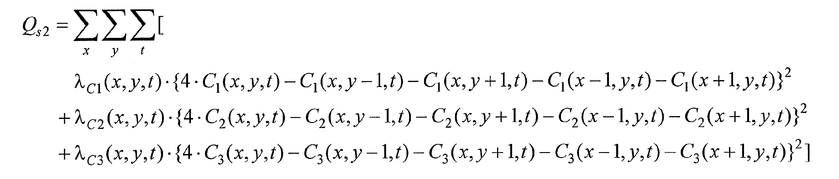
  • Equation 13 defines the square sum of the second-order difference values in the xy space direction of the pixel values expressed in the new orthogonal coordinate system of the target moving image.
  • changes in pixel values expressed in a new orthogonal coordinate system in pixels spatially adjacent in each frame image of the target moving image are uniform (that is, pixel values are continuous).
  • the condition Q s2 for decreasing the value is defined.
  • That the value of the condition Q s2 should be small indicates that the colors of spatially adjacent pixels in the target moving image should be continuous.
  • ⁇ C1 (x, y), ⁇ C2 (x, y), and ⁇ C3 (x, y) are for the conditions set using the coordinate values of the C 1 axis, C 2 axis, and C 3 axis, respectively. , Which is a weight applied at the pixel position (x, y) of the target moving image, and is determined in advance.
  • the values of ⁇ C1 (x, y), ⁇ C2 (x, y), and ⁇ C3 (x, y) are set along each eigen vector axis.
  • a suitable value of ⁇ can be set according to a dispersion value that varies depending on the eigenvector axis. That is, since the variance is small in the direction of the non-principal component and the square sum of the second-order difference can be expected to be small, the value of ⁇ is increased. Conversely, the value of ⁇ is relatively small in the direction of the principal component.
  • the coordinate values of the ⁇ axis and the ⁇ axis representing the color information and the signal intensity are represented by introducing a spherical coordinate system ( ⁇ , ⁇ , r). Since conditions can be set by using the coordinate values of the r-axis coordinate values individually, and a suitable weight parameter ⁇ can be assigned to the color information and the signal intensity when setting the conditions, it is possible to generate a high-quality image. There is an advantage that it becomes easy.
  • the condition is set using the coordinate value of the eigenvector axis that reflects the color change that affects more pixels. Therefore, it is possible to expect an improvement in the image quality of the obtained target moving image as compared with a case where conditions are simply set using pixel values of red, green, and blue color components.
  • step 307 a target moving image is generated that satisfies the constraint conditions set by the third condition setting unit 103a, the second condition setting unit 103b, and the first condition setting unit 103c.
  • an evaluation function J consisting of the constraint conditions is set.
  • An example of J is shown in (Formula 14).
  • H R , H G , and H B are low resolutions from the respective color images R H , G H , and B H of the target moving image g to the acquired images R L , G L , and B L (vector notation).
  • H R and H B are conversions with a lower resolution as in (Equation 1)
  • H G are conversions with a lower frame rate as in (Equation 2).
  • the evaluation function J is not limited to the above, and the term in (Equation 14) may be replaced with a term consisting of a similar expression, or a new term representing a different condition may be added.
  • each color image R H , G of the target moving image is obtained by obtaining each pixel value of the target moving image that makes the value of J in (Equation 14) as small as possible (desirably minimized) in the color image generating unit 103d.
  • H and B H are generated.
  • the expressions obtained by differentiating J from the respective pixel value components of the color images R H , G H , and B H of the target moving image are all set to 0 (Expression 15). It may be obtained by solving an equation, or may be obtained by using an iterative calculation type optimization method such as the steepest gradient method.
  • 12 and 13 show examples of images obtained by photographing the same subject with different colors when saturation does not occur.
  • 12A and 12B show continuous frame images of long-exposure G images with low speed and high resolution.
  • a circular subject 91 is moving in the lower right direction, and motion blur occurs due to long exposure.
  • (A) to (f) and (g) to (l) in FIG. 13 respectively represent high-speed and low-resolution RB continuous frame images. Although the number of frames in FIG. 13 is larger than that in the image in FIG. 12, the resolution is low.
  • step 304 the light amount determination unit 104 determines that no saturation occurs, and in step 305, the first condition setting unit 103c sets the first condition for all frames and pixels based on the determination result.
  • image generation is performed in step 307, the spatio-temporal information of the images is complemented between the RGB images, and high-speed and high-resolution RGB images are obtained as shown in FIGS. The temporal timing of each frame is the same as in FIG.
  • FIG. 15 shows an image example in which the G image is saturated with the same subject arrangement as in FIG. In the figure, a saturated pixel region 121 is shown.
  • FIG. 16 shows an example in which the images in FIG. 15 and FIG. 13 are combined and an image is generated without determining saturated pixels.
  • the pixel value of the RGB image has an error at the frame and pixel position corresponding to the saturated region of G (white circles 131 to 133).
  • the saturation region of the G image the pixel value becomes darker than the correct pixel value (a value larger than the saturation value) according to the first condition.
  • the G image becomes dark in the saturation region, the color with the surrounding region becomes discontinuous, and it becomes difficult to satisfy the constraint of the continuity of pixel values (second condition).
  • the saturated region is determined as shown in the present embodiment (step 304), and restraint due to the first condition is suppressed in the saturated region (step 305).
  • the acquired image as shown in FIG.
  • FIG. 14 it is possible to generate an image in which the influence of saturation (generation of false colors due to RGB value errors, etc.) is suppressed. This is because, in the saturation region, the constraint due to the first condition that contradicts the constraint on the continuity of the pixel values is suppressed, and the image is generated by the constraint condition that is not contradictory to each other other than the constraint due to the first condition. This is because color generation can be suppressed.
  • FIG. 17 shows an example of pixel groups for R and G images.
  • the pixel values in the row direction of the pixel group indicated by diagonal lines will be described as an example.
  • the pixel positions in the row direction are indicated by 1 to 9.
  • FIG. 18A and 18B show the relationship between the pixel position and the pixel value for the R and G images.
  • FIG. 18A shows an example in which blackening and saturation occur in the pixel value
  • FIG. 18B is a graph schematically showing the effect of the processing according to the above-described embodiment. The following description will be made using R and G images, but the same effect can be obtained in the same procedure with other color combinations.
  • the G pixel at the pixel positions 4 to 6 is saturated with the pixel value indicated by the arrow.
  • an image as shown in FIG. 18B can be obtained.
  • the G saturation region at the pixel positions 4 to 6 greatly deviates from the value of the acquired image and deviates from the constraint by the first condition, but the continuity constraint of the pixel value (second By generating an image so that the G pixel value (solid line) changes together with the R pixel value change (dotted line) in accordance with the conditions and motion constraints, a color image with reduced false colors can be obtained.
  • the light amount determination unit 104 determines whether or not the image is blacked out, and generates an image in a region determined to be blacked out while restraining the constraint on the first condition of the R image.
  • the R pixel value (dotted line) changes together with the change of the G pixel value (solid line) in accordance with the constraint of the continuity of the pixel value.
  • An image is generated as follows. As a result, a color image that avoids black crushing can be obtained even in a blacked out region. In the case of blackout, the occurrence of false colors is less noticeable as in the case of pixel saturation due to the darkness, but the effect of the present invention has the effect that colors that are not blackout can be reproduced.
  • the pixel value at which saturation or blackout occurs may vary from color to color depending on the characteristics of the image sensor. For example, in FIG. 18A, it has been described that the green (G) pixel values at the pixel positions 4 to 6 are saturated, but the larger red (R) pixel values at the pixel positions 4 to 6 are still saturated. Sometimes not.
  • strengthening the second condition means reducing the second-order differential value of a pixel in which saturation or blackout has occurred.
  • to strengthen the motion constraint condition means to overestimate the value of the motion constraint condition (Equation 5) in the evaluation formula for a pixel in which saturation or blackout has occurred.
  • the value of conf (x, y, t) of the pixel in which saturation or blackout has occurred is made larger than the already set value. For example, it is set to a predetermined constant value.
  • the reliability of motion detection may be reduced for the pixel position that the light amount determination unit 104 determines in step 304 that saturation or blackout has occurred.
  • the method for reducing the reliability of motion detection is determined in advance. For example, the reliability is set to 0.
  • the color image that is determined to have been saturated or blacked out in step 304 may be excluded from the color image used for motion detection. This also can reduce motion detection errors due to saturation and blackout.
  • FIG. 19 shows an image of the doll's head (RGB color image is converted into a luminance image), and is a broken-line rectangular area of the head ribbon (position of the arrow, right side is an enlarged view). Saturated. The result of image generation without performing saturation determination is the image of FIG. In the rectangular area of the broken line, a color different from that of the surrounding ribbon (white) is generated, resulting in a dark image (shaded area in the enlarged view).
  • FIG. 19B shows the result of the processing according to the present embodiment.
  • the processing according to the present embodiment when a moving image having a high spatio-temporal resolution is generated by combining moving images having different spatio-temporal resolution and color, an acquired image including saturation and blackout is obtained. Therefore, it is possible to generate an image with reduced image quality degradation. As a result, it is possible to generate an image that exceeds the gradation range (dynamic range) that can be expressed in the acquired image in the bright direction in the saturated region and in the dark direction in the blacked-out region. As described above, the present embodiment has an effect of expanding the dynamic range of the generated color image by combining the color images having different dynamic ranges.
  • FIG. 20 is a functional block diagram illustrating an internal configuration of the image generation apparatus 30 according to the second embodiment.
  • the configuration and operation of the functional block are almost the same as those in the first embodiment, but a light amount control unit 105 is newly provided.
  • the light amount control unit 105 controls the exposure amount when the imaging apparatus 10 captures a moving image.
  • the exposure amount is controlled based on the determination by the light amount determination unit 104. Specifically, it can be realized by changing the exposure time for each color image.
  • FIG. 21 is a flowchart showing the procedure of the light amount control process.
  • the light amount determination unit 104 determines saturation / blackout for each frame / pixel.
  • the light amount control unit 105 determines the exposure amount of any color (for example, G). Reduce.
  • the light amount control unit 105 determines the exposure amount of any color (for example, G). Increase.
  • the exposure amount may be controlled in units of pixels or in units of RGB color images.
  • the exposure amount of one of the colors when all the colors are saturated, by reducing the exposure amount of one of the colors, an image in which saturation is suppressed for at least one color is obtained. It becomes easy to obtain the effect of the configuration. That is, by generating a color image that is not saturated in a region where all the colors are saturated and the constraint due to the first condition is suppressed, another constraint condition (temporal and spatial) is generated based on the image information of the unsaturated color. The image quality can be expected to be higher than when all colors are saturated. At this time, it is possible to reduce the exposure amount for all the colors so that all the colors become non-saturated, but blackout easily occurs.
  • the effect of the first embodiment can suppress the blackout in the target moving image and generate an image with an expanded dynamic range.
  • the effect of the first embodiment can suppress the saturation in the target moving image and generate an image with an expanded dynamic range.
  • FIG. 22 is a functional block diagram showing the internal configuration of the image generation apparatus 30 in the present embodiment.
  • FIG. 23 is a flowchart illustrating a processing procedure of the image generation apparatus 30 according to the present embodiment.
  • the configuration and operation of the image generation apparatus 30 are substantially the same as those in the first embodiment, but the difference is that the image generation apparatus 30 according to the present embodiment does not have a motion detection unit. Therefore, the flowchart shown in FIG. 23 does not include processing relating to image motion (steps 302 and 303 in FIG. 3).
  • the color image generation unit 103d generates a new moving image using the conditions set by the first condition setting unit 103c and the conditions set by the second condition setting unit 103b. Even when the motion constraint is not used, the light quantity determination unit determines saturation or blackout, and performs the first condition setting based on the determination result, whereby the target moving image corresponding to the saturation region can be improved in image quality.
  • the image generation system 100 having the display device 40 has been described so far. However, like the video camera 300 shown in FIG. 24, the display device 40 may be omitted from the image generation system 100 shown in FIG. Note that a camera with a moving image recording / playback function configured by adding the display device 40 to the video camera 300 illustrated in FIG. 24 is in the category of the configuration illustrated in FIG. 1 and the like.
  • the imaging device 10 may be omitted from the image generation system 100 shown in FIG.
  • Such a display device 400 can receive a moving image of a plurality of color components and generate and display a target moving image with an improved frame rate. Even when the imaging device 10 is not included, such a display device is in the category of the image generation system 100.
  • the display device 400 can receive “moving images of multi-color components” by various methods.
  • a moving image of a multi-color component may be extracted from moving image data recorded in advance on a semiconductor memory card (for example, an SD card) 250, or may be extracted from a broadcast wave using the antenna 251.
  • the moving image may be acquired via a network 252 such as the Internet.
  • a network 252 such as the Internet.
  • two or all of the semiconductor memory card 250, the antenna 251 and the network 252 may be available.
  • the image generating device 30 captures shooting conditions such as exposure timing (FIG. 7) of moving images of the respective color components. Need information about. Therefore, the image acquisition unit 101 only has to receive the video signal 210 in the format shown in FIG. 4C, acquire the shooting condition information from the identification header 210a, and acquire the moving image data 210b.
  • shooting conditions such as exposure timing (FIG. 7) of moving images of the respective color components. Need information about. Therefore, the image acquisition unit 101 only has to receive the video signal 210 in the format shown in FIG. 4C, acquire the shooting condition information from the identification header 210a, and acquire the moving image data 210b.
  • the transmission method of the video signal 210 is arbitrary.
  • the video signal 210 shown in FIG. 4C may be packetized and transmitted by broadcast waves for network communication.
  • Part or all of the image generation processing performed by the image processing apparatus of the present invention may be executed by a dedicated hardware device, a communication device arranged in a computer terminal device, a wireless base station, or the like, and a stand-alone general-purpose device
  • the image generation processing of the present invention may be performed by a CPU built in a computer or the like executing a predetermined computer program.
  • a computer program defines the processing procedure of the illustrated flowchart.
  • the CPU that has executed the computer program causes the image processing apparatus to operate according to the processing procedure either by operating according to the processing procedure or by instructing and operating other components illustrated.
  • the present invention is an image generation technique for generating a new moving image from a plurality of moving images.
  • an image generation device that generates a high-speed, high-resolution moving image from a high-speed, low-resolution moving image and a low-speed, high-resolution moving image (or still image), a video device or system incorporating such a device, a video composition device, a video It can be used as an editing device, an image restoration device, an image restoration program, and the like.
  • DESCRIPTION OF SYMBOLS 10 Imaging device 20 Image storage device 30 Image generation device 40
  • Display device 100 Image generation system 101 Image acquisition part 101a High speed image acquisition part 101b Low speed image acquisition part 102 Motion detection part 102a Motion distribution calculation part 102b Reliability distribution calculation part 103 Image processing Unit 103a third condition setting unit 103b second condition setting unit 103c first condition setting unit 103d color image generation unit 104 light amount determination unit 105 light amount control unit 106 output unit 300 camera 400 display device

Landscapes

  • Engineering & Computer Science (AREA)
  • Physics & Mathematics (AREA)
  • Theoretical Computer Science (AREA)
  • General Physics & Mathematics (AREA)
  • Spectroscopy & Molecular Physics (AREA)
  • Computing Systems (AREA)
  • Multimedia (AREA)
  • Signal Processing (AREA)
  • Studio Devices (AREA)
  • Color Television Image Signal Generators (AREA)

Abstract

An image is obtained with higher resolution frame rates than otherwise possible even if saturation arises with images photographed with exposure quantities secured. An image generating device generates a new motion video image that represents a video subject from a first and a second motion video image which are motion video images of a first and a second color component of the subject thereof. The image generating device comprises an image acquisition unit, which acquires a first and a second motion video image that mutually differ in resolution and either frame rate or exposure time; a light quantity determination unit, which determines whether each pixel of each frame image of the first and the second motion video image is either saturated or having a loss of dark detail, on the basis of the pixel value of each pixel thereof; and an image processing unit that generates a new image from the first and the second motion video image that has both a frame rate greater than or equal to the frame rates thereof, and a resolution upon each frame image that is greater than or equal to the resolutions thereof. The image processing unit generates a new motion video image with pixels that are determined not to be either saturated or have the loss of dark detail, which satisfies a first condition that the error between the acquired first and second motion video image pixel values and the total of pixel values of the new motion video image frame image that corresponds temporally with the pixels that are thus not determined is less than a prescribed value, and generates a new motion video image, with pixels that are determined to be either saturated or have the loss of dark detail, which does not satisfy the first condition.

Description

画像処理装置、画像生成システム、方法、およびプログラムImage processing apparatus, image generation system, method, and program
 本発明は、動画像を生成する画像処理に関し、特に、同一の対象を異なる撮影条件の下で撮影して得られた複数の動画像から、その対象を表す新たな動画像を生成する画像処理に関する。 The present invention relates to image processing for generating a moving image, and in particular, image processing for generating a new moving image representing a target from a plurality of moving images obtained by shooting the same target under different shooting conditions. About.
 画素の微細化により撮像素子の多画素化と小型化が進み、小型・安価なカメラで高解像度の撮像が可能になってきた。微細化の結果、個々の画素の受光面積が減少するため、相対的なノイズの増加(SN比の低下)が問題となる。特に、動きのある被写体の静止画撮影や動画撮影では露出時間を長くできないため、光量不足によるSN比低下(画質劣化)の問題が顕著になる。 As the pixels become finer, the number of pixels and the size of the image sensor have increased, and high-resolution imaging has become possible with a small and inexpensive camera. As a result of miniaturization, the light receiving area of each pixel is reduced, so that a relative increase in noise (decrease in the SN ratio) becomes a problem. In particular, since the exposure time cannot be increased in still image shooting or moving image shooting of a moving subject, the problem of SN ratio reduction (image quality degradation) due to insufficient light quantity becomes significant.
 上記の問題の対策として、受光後に電気的に信号増幅することにより、光量不足の撮影画像を明るくする方法が考えられる。しかしながらその方法ではノイズも同時に増幅され、SN比は改善しない。一方、露出時間を長くして受光量を増す方法が考えられる。しかしながら、この方法では被写体が動くことで動きブレが生じ、鮮明な画像は撮影できない。また、受光量を増すために、レンズ等の光学系を大きくすると、コストの増加や可搬性の低下という課題が生じる。 As a countermeasure against the above problem, a method of brightening a photographed image with insufficient light quantity by electrically amplifying the signal after receiving light can be considered. However, this method also amplifies noise at the same time and does not improve the S / N ratio. On the other hand, a method of increasing the amount of received light by extending the exposure time can be considered. However, in this method, motion blur occurs due to the movement of the subject, and a clear image cannot be taken. Further, when an optical system such as a lens is enlarged in order to increase the amount of received light, there arises a problem of an increase in cost and a decrease in portability.
 光量不足の条件下で高解像度の動画像を取得する従来の装置として、同一の対象を撮影して得られた露出時間の長い静止画と動画とを用いて、新たな動画像を生成する画像生成装置がある(例えば、特許文献1参照)。図26は、特許文献1に記載された従来の画像生成装置の処理手順を示すフローチャートである。図26のステップA1では、同一事象を撮影して得られた高速低解像度動画像と長時間露出の低速高解像度動画像とが取得される。ステップA2では、低速高解像度動画像の露光期間における新たな動画像のフレームの合計と低速高解像度動画像との誤差を減少させて画像が生成される。ステップA3では、生成画像が出力される。 As a conventional device that acquires high-resolution moving images under insufficient light conditions, images that generate new moving images using still images and moving images with long exposure times obtained by shooting the same object There exists a production | generation apparatus (for example, refer patent document 1). FIG. 26 is a flowchart showing a processing procedure of the conventional image generating apparatus described in Patent Document 1. In step A1 of FIG. 26, a high-speed low-resolution moving image obtained by photographing the same event and a low-speed high-resolution moving image with long exposure are acquired. In step A2, an image is generated by reducing an error between the total of new moving image frames during the exposure period of the low-speed high-resolution moving image and the low-speed high-resolution moving image. In step A3, the generated image is output.
特許第4215267号明細書Japanese Patent No. 4215267
 上述の画像生成装置の構成では、長時間の露出の撮影を行うため、光量が多い被写体を撮影した場合に、当該被写体領域で画素飽和が生じることがある。当該飽和画素領域では、本来得られるべき画像のフレーム加算値は飽和画素値よりも大きい。そのため、従来技術の方法により、前記フレーム加算値が入力画像の画素値(飽和画素値)との誤差が小さくなるように画像を生成すると、矛盾が生じ、生成画像の画質が低下し、輝度誤差や偽色の発生する場合があった。 In the configuration of the image generation apparatus described above, since long exposure exposure is performed, pixel saturation may occur in the subject area when a subject with a large amount of light is captured. In the saturated pixel region, the frame addition value of the image to be originally obtained is larger than the saturated pixel value. For this reason, when an image is generated by the prior art method so that the error between the frame addition value and the pixel value (saturated pixel value) of the input image becomes small, a contradiction occurs, the image quality of the generated image decreases, and a luminance error occurs. There were cases where false colors were generated.
 本発明は、従来の課題を解決するためになされたものであり、その目的は、長時間露出などにより露光量を確保して撮影した画像から高解像度高フレームレート画像を得る際、飽和が発生した場合でも高画質の画像を得ることにある。 The present invention has been made to solve the conventional problems, and its purpose is to generate saturation when obtaining a high-resolution and high-frame-rate image from an image that has been captured with a sufficient exposure amount by long-time exposure or the like. Even in this case, it is to obtain a high-quality image.
 本発明による画像生成装置は、被写体の第1色成分の動画像である第1動画像、および、前記被写体の第2色成分の動画像である第2動画像から、前記被写体を表す新たな動画像を生成する画像生成装置であって、互いに、解像度と、フレームレートもしくは露出時間とが異なっている前記第1動画像および前記第2動画像を取得する画像取得部と、前記第1動画像および前記第2動画像の各フレーム画像中の各画素における画素値に基づいて各画素が飽和もしくは黒つぶれしているか否かを判定する光量判定部と、前記第1動画像および前記第2動画像から、前記第1動画像および前記第2動画像のフレームレート以上のフレームレートで、かつ、各フレーム画像の解像度が前記第1動画像および前記第2動画像の解像度以上である新たな画像を生成する画像処理部であって、前記光量判定部が飽和または黒つぶれしていると判定していない画素に対しては、取得された前記第1動画像および前記第2動画像の画素値と前記画素と時空間的に対応する前記新たな動画像のフレーム画像の画素値の合計との誤差が所定値よりも小さいことを表す第1条件を満たす新たな動画像を生成し、前記光量判定部が飽和または黒つぶれしていると判定した画素に対しては、前記第1条件を満たさない新たな動画像を生成する画像処理部とを備えている。 The image generation apparatus according to the present invention is a new video representing a subject from a first moving image that is a moving image of the first color component of the subject and a second moving image that is a moving image of the second color component of the subject. An image generation device for generating a moving image, the image acquisition unit acquiring the first moving image and the second moving image having different resolution and frame rate or exposure time, and the first moving image A light amount determination unit that determines whether or not each pixel is saturated or blacked based on a pixel value in each pixel in each frame image of the image and the second moving image; and the first moving image and the second moving image From a moving image, a new frame rate that is equal to or higher than the frame rate of the first moving image and the second moving image, and the resolution of each frame image is equal to or higher than the resolution of the first moving image and the second moving image. An image processing unit that generates an image, and the pixels of the first moving image and the second moving image that are acquired for pixels that the light amount determination unit has not determined to be saturated or blackened Generating a new moving image satisfying a first condition indicating that an error between a value and a sum of pixel values of a frame image of the new moving image corresponding in time and space to the pixel is smaller than a predetermined value, An image processing unit that generates a new moving image that does not satisfy the first condition is provided for a pixel that is determined to be saturated or blackened by the light amount determination unit.
 前記第1色成分は赤または青の少なくとも一方であり、前記第2色成分は緑であってもよい。 The first color component may be at least one of red and blue, and the second color component may be green.
 前記光量判定部は、各画素における光量が、予め定められた飽和値以上の場合に飽和していると判定してもよい。 The light amount determination unit may determine that the light amount in each pixel is saturated when the light amount is equal to or greater than a predetermined saturation value.
 前記光量判定部は、各画素における光量が、予め定められた黒つぶれ値以下の場合に黒つぶれしていると判定してもよい。 The light amount determination unit may determine that the amount of light in each pixel is blacked out when the amount of light in each pixel is equal to or less than a predetermined blacked out value.
 前記飽和値は、前記第1色成分および前記第2色成分の各々に設定されてもよい。 The saturation value may be set for each of the first color component and the second color component.
 前記黒つぶれ値が、前記第1色成分および前記第2色成分の各々に設定されてもよい。 The blackout value may be set for each of the first color component and the second color component.
 前記光量判定部が、画素が飽和していると判定したときは、前記画像処理部は前記画素の画素値を低減させ、前記光量判定部が、画素が黒つぶれしていると判定したときは前記画像処理部は前記画素の画素値を増加させてもよい。 When the light amount determination unit determines that the pixel is saturated, the image processing unit reduces the pixel value of the pixel, and when the light amount determination unit determines that the pixel is blackened The image processing unit may increase the pixel value of the pixel.
 前記画像生成装置は、生成する新たな動画像内の時空間的に隣り合う画素の色が連続すべきことを表す時空間的連続性に関する第2条件を設定する第2条件設定部をさらに備え、前記画像処理部は、前記第2条件を満たす新たな動画像を生成してもよい。 The image generation apparatus further includes a second condition setting unit that sets a second condition relating to spatiotemporal continuity representing that the colors of temporally and spatially adjacent pixels in a new moving image to be generated should be continuous. The image processing unit may generate a new moving image that satisfies the second condition.
 前記第2条件設定部は、前記時空間的連続性に関する第2条件を、画素の信号強度および色彩について個別に前記第2条件を設定してもよい。 The second condition setting unit may set the second condition relating to the spatiotemporal continuity and the second condition individually for the signal intensity and color of the pixel.
 前記第2条件設定部は、設定される前記第2条件に対して、前記新たな動画像の各画素の画素位置において適用される重みを決定し、前記第2条件設定部は、取得された前記第1動画像および前記第2動画像の空間的微分値が大きい位置の重みを下げて前記第2条件を設定してもよい。 The second condition setting unit determines a weight to be applied at a pixel position of each pixel of the new moving image with respect to the set second condition, and the second condition setting unit is acquired The second condition may be set by reducing the weight of the position where the spatial differential value of the first moving image and the second moving image is large.
 前記第2条件設定部は、前記画素の色彩の時空間的連続性を、前記画素の信号強度の時空間的連続性よりも重みを大きくして前記第2条件を設定してもよい。 The second condition setting unit may set the second condition by setting the spatiotemporal continuity of the color of the pixel to be greater than the spatiotemporal continuity of the signal intensity of the pixel.
 前記第2条件設定部は、前記時空間的連続性に関する第2条件を、取得された前記画像の色空間における画素値の分散の大きさに応じて選択される方向、および、前記方向に直交する方向のそれぞれに設定してもよい。 The second condition setting unit is configured to select a second condition related to the spatiotemporal continuity according to a direction selected according to the magnitude of dispersion of pixel values in the color space of the acquired image, and orthogonal to the direction. It may be set for each direction.
 前記第2条件設定部は、前記光量判定部が飽和もしくは黒つぶれしていると判定した画素の画素位置における前記第2条件を、飽和もしくは黒つぶれしていると判定されなかった画素の画素位置における前記第2条件よりも強く設定してもよい。 The second condition setting unit determines the second condition at the pixel position of the pixel determined to be saturated or blacked out by the light amount determination unit, and the pixel position of the pixel not determined to be saturated or blacked out You may set stronger than the said 2nd condition in.
 前記画像生成装置は、前記第1動画像と前記第2動画像とを撮像する撮像装置の露光量を調整する光量制御部をさらに備え、前記第1動画像および前記第2動画像の各々について、前記光量判定部が、各フレーム画像の同一位置の全ての色が飽和していると判定したときは、前記光量制御部は、一部の色成分の動画像を取得するための露光量を低減させてもよい。 The image generation device further includes a light amount control unit that adjusts an exposure amount of an imaging device that captures the first moving image and the second moving image, and each of the first moving image and the second moving image. When the light amount determination unit determines that all the colors at the same position in each frame image are saturated, the light amount control unit determines an exposure amount for acquiring a moving image of some color components. It may be reduced.
 光量判定部が各フレーム画像の同一位置の全ての色が飽和していると判定した場合、光量制御部は、少なくとも1つの色成分の動画像の撮像時において前記撮像装置の露光量を低減させてもよい。 When the light amount determination unit determines that all the colors at the same position of each frame image are saturated, the light amount control unit reduces the exposure amount of the imaging device when capturing a moving image of at least one color component. May be.
 前記画像生成装置は、取得された前記画像の動きを検出する動き検出部と、前記動きの検出結果に基づき、生成する新たな動画像内の動きベクトルに沿った画素値が一致すべきことを表す第3の条件を設定する第3の条件設定部とをさらに備え、前記画像処理部は、前記第3の条件を満たす新たな動画像を生成してもよい。 The image generation apparatus determines that pixel values along a motion vector in a new moving image to be generated should match based on a motion detection unit that detects the acquired motion of the image and the detection result of the motion. A third condition setting unit that sets a third condition to be expressed, and the image processing unit may generate a new moving image that satisfies the third condition.
 前記第3の条件設定部は、前記光量判定部が飽和もしくは黒つぶれと判定した画素位置に対する前記第3の条件を、飽和もしくは黒つぶれしていると判定されなかった画素位置における前記第3の条件よりも強く設定してもよい。 The third condition setting unit sets the third condition for the pixel position determined to be saturated or blacked out by the light amount determining unit as to the third position at the pixel position not determined to be saturated or blacked out. You may set more strongly than conditions.
 本発明による画像生成システムは、撮像装置と、前記撮像装置で撮影した画像を記録する記憶装置と、前記記憶装置の画像を用いて前記新たな動画像を生成する、請求項1に記載の画像生成装置とを備えている。 2. The image generation system according to claim 1, wherein the image generation system according to the present invention generates the new moving image using an imaging device, a storage device that records an image captured by the imaging device, and an image of the storage device. And a generating device.
 本発明による他の画像生成システムは、上述の画像生成装置と、前記画像生成装置が生成した前記新たな動画像を表示する表示装置とを備えている。 Another image generation system according to the present invention includes the above-described image generation device and a display device that displays the new moving image generated by the image generation device.
 前記画像生成装置は、前記第1画像および前記第2画像の各信号を、メモリカード、アンテナおよびネットワークの少なくとも1つを経由して取得してもよい。 The image generation apparatus may acquire each signal of the first image and the second image via at least one of a memory card, an antenna, and a network.
 本発明による方法は、被写体の第1色成分の動画像である第1動画像、および、前記被写体の第2色成分の動画像である第2動画像から、前記被写体を表す新たな動画像を生成する画像生成方法であって、互いに、解像度と、フレームレートもしくは露出時間とが異なっている前記第1動画像および前記第2動画像を取得するステップと、前記第1動画像および前記第2動画像の各フレーム画像中の各画素における画素値に基づいて各画素が飽和もしくは黒つぶれしているか否かを判定するステップと、前記第1動画像および前記第2動画像から、前記第1動画像および前記第2動画像のフレームレート以上のフレームレートで、かつ、各フレーム画像の解像度が前記第1動画像および前記第2動画像の解像度以上である新たな画像を生成するステップであって、判定する前記ステップにおいて飽和または黒つぶれしていると判定されていない画素に対しては、取得された前記第1動画像および前記第2動画像の画素値と前記画素と時空間的に対応する前記新たな動画像のフレーム画像の画素値の合計との誤差が所定値よりも小さいことを表す第1条件を満たす新たな動画像を生成し、判定する前記ステップにおいて飽和または黒つぶれしていると判定された画素に対しては、前記第1条件を満たさない新たな動画像を生成する新たな画像を生成するステップとを包含する。 The method according to the present invention provides a new moving image representing a subject from a first moving image that is a moving image of the first color component of the subject and a second moving image that is a moving image of the second color component of the subject. An image generating method for generating the first moving image and the second moving image, each having a different resolution and frame rate or exposure time, and the first moving image and the first moving image. A step of determining whether or not each pixel is saturated or blacked based on a pixel value in each pixel in each frame image of the two moving images; and from the first moving image and the second moving image, the first Generate a new image having a frame rate equal to or higher than the frame rate of one moving image and the second moving image, and the resolution of each frame image being equal to or higher than the resolution of the first moving image and the second moving image. For the pixels that are not determined to be saturated or blackened in the determining step, the pixel values of the acquired first moving image and the second moving image, and the pixels A new moving image that satisfies the first condition indicating that an error from the sum of the pixel values of the frame image of the new moving image corresponding in time and space is smaller than a predetermined value is generated and saturated in the step of determining Alternatively, a step of generating a new image for generating a new moving image that does not satisfy the first condition is included for pixels determined to be blackened.
 本発明によるコンピュータプログラムは、被写体の第1色成分の動画像である第1動画像、および、前記被写体の第2色成分の動画像である第2動画像から、前記被写体を表す新たな動画像を生成する画像生成装置のコンピュータによって実行されるコンピュータプログラムであって、前記コンピュータプログラムは、前記コンピュータに対し、互いに、解像度と、フレームレートもしくは露出時間とが異なっている前記第1動画像および前記第2動画像を取得するステップと、前記第1動画像および前記第2動画像の各フレーム画像中の各画素における画素値に基づいて各画素が飽和もしくは黒つぶれしているか否かを判定するステップと、前記第1動画像および前記第2動画像から、前記第1動画像および前記第2動画像のフレームレート以上のフレームレートで、かつ、各フレーム画像の解像度が前記第1動画像および前記第2動画像の解像度以上である新たな画像を生成するステップであって、判定する前記ステップにおいて飽和または黒つぶれしていると判定されていない画素に対しては、取得された前記第1動画像および前記第2動画像の画素値と前記画素と時空間的に対応する前記新たな動画像のフレーム画像の画素値の合計との誤差が所定値よりも小さいことを表す第1条件を満たす新たな動画像を生成し、判定する前記ステップにおいて飽和または黒つぶれしていると判定された画素に対しては、前記第1条件を満たさない新たな動画像を生成する新たな画像を生成するステップとを実行させる。 A computer program according to the present invention provides a new moving image representing a subject from a first moving image that is a moving image of the first color component of the subject and a second moving image that is a moving image of the second color component of the subject. A computer program executed by a computer of an image generating apparatus for generating an image, wherein the computer program is different from the computer in the first moving image and the resolution, the frame rate, or the exposure time. The step of obtaining the second moving image and determining whether each pixel is saturated or blacked based on a pixel value in each pixel in each frame image of the first moving image and the second moving image A frame rate of the first moving image and the second moving image from the first moving image and the second moving image. Generating a new image having a frame rate equal to or higher than the resolution of the first moving image and a resolution of each frame image equal to or higher than the resolution of the first moving image and the second moving image. For the pixels that are not determined to be crushed, the pixel values of the acquired first moving image and second moving image and the frame image of the new moving image that temporally and spatially corresponds to the pixels A new moving image that satisfies the first condition indicating that the error from the sum of the pixel values is smaller than a predetermined value is generated, and the pixel determined to be saturated or blacked out in the determining step Generating a new image that generates a new moving image that does not satisfy the first condition.
 本発明の画像生成装置によれば、長時間露出などによって飽和した画像領域に対し、生成される動画像の複数フレームの合計と静止画との誤差を許容して、動画像生成する。これにより、飽和領域に対応して生成される動画像を高画質化することができる。 According to the image generation apparatus of the present invention, a moving image is generated by allowing an error between the sum of a plurality of frames of a generated moving image and a still image for an image region saturated by long-time exposure or the like. Thereby, it is possible to improve the image quality of the moving image generated corresponding to the saturated region.
実施形態1に係る画像生成システム100のハードウェア構成を示すブロック図である。1 is a block diagram illustrating a hardware configuration of an image generation system 100 according to Embodiment 1. FIG. 図1に示された画像生成装置30の内部構成を示す機能ブロック図である。It is a functional block diagram which shows the internal structure of the image generation apparatus 30 shown by FIG. 画像生成装置30の実行する処理の手順を示すフローチャートである。4 is a flowchart illustrating a procedure of processing executed by the image generation device 30. (a)および(b)は、高速画像取得部101aで取得される高速低解像度動画像と低速画像取得部101bで取得される低速高解像度動画像との関係を示す図である。(A) And (b) is a figure which shows the relationship between the high-speed low-resolution moving image acquired by the high-speed image acquisition part 101a, and the low-speed high-resolution moving image acquired by the low-speed image acquisition part 101b. 低速高解像度動画像と高速低解像度動画像の露光タイミングの関係を示す図である。It is a figure which shows the relationship between the exposure timing of a low-speed high-resolution moving image and a high-speed low-resolution moving image. 撮影条件の情報が記述された識別ヘッダー210aと、動画像データ210bとを有する映像信号210のフォーマットの一例を示す図である。It is a figure which shows an example of the format of the video signal 210 which has the identification header 210a in which the information of imaging conditions was described, and the moving image data 210b. (a)~(c)は、撮像装置の構成例を示す図である。(A)-(c) is a figure which shows the structural example of an imaging device. (a)~(c)は、高速高解像度動画像の画素値と、高速画像取得部101aに取得された高速低解像度動画像の画素値と、低速画像取得部101bに取得された低速高解像度動画像の画素値との関係を説明する図である。(A) to (c) are pixel values of a high-speed and high-resolution moving image, pixel values of a high-speed and low-resolution moving image acquired by the high-speed image acquisition unit 101a, and low-speed and high-resolution acquired by the low-speed image acquisition unit 101b. It is a figure explaining the relationship with the pixel value of a moving image. (a)および(b)は、撮影強度の時間的変化を示す図である。(A) And (b) is a figure which shows the time change of imaging | photography intensity | strength. (a)~(c)は画素値と撮像時の入射光量との関係を説明する図である。(A)-(c) is a figure explaining the relationship between a pixel value and the incident light quantity at the time of imaging. (a)および(b)はそれぞれ、動き検出処理に関連する、フレーム番号tとt+1における画素配置を表す図である。(A) And (b) is a figure showing the pixel arrangement | positioning in the frame numbers t and t + 1 relevant to a motion detection process, respectively. RGB色空間と球面座標系(θ、ψ、r)との対応例を示す図である。It is a figure which shows the example of a response | compatibility with RGB color space and a spherical coordinate system ((theta), (psi), r). RGB色空間における固有ベクトル軸(C1,C2,C3)の例を示す図である。It is a figure which shows the example of the eigenvector axis | shaft (C1, C2, C3) in RGB color space. (a)および(b)は飽和が生じていないときに同一被写体を異なる色で撮影した画像の例を表す図である。(A) And (b) is a figure showing the example of the image which image | photographed the same subject with a different color when saturation has not arisen. (a)~(f)と(g)~(l)は、それぞれ高速低解像度のRBの連続するフレーム画像を示す図である。(A) to (f) and (g) to (l) are diagrams showing high-speed and low-resolution RB continuous frame images, respectively. (a)~(r)は高速高解像度のRGB画像を示す図である。(A) to (r) are diagrams showing high-speed and high-resolution RGB images. (a)および(b)は、図12と同じ被写体の配置でG画像に飽和領域121が存在するときの画像例を示す図である。(A) And (b) is a figure which shows the example of an image when the saturation area | region 121 exists in G image by the same object arrangement | positioning as FIG. (a)~(r)は、図15および図13の画像を組み合わせて、飽和画素の判定を行わずに生成した画像の例を示す図である。(A)-(r) is a figure which shows the example of the image produced | generated without performing the determination of a saturated pixel combining the image of FIG. 15 and FIG. RとG画像についての画素群の例を示す図である。It is a figure which shows the example of the pixel group about R and G image. (a)および(b)は、RとG画像についての画素位置と画素値との関係を示す図である。(A) And (b) is a figure which shows the relationship between the pixel position and pixel value about R and G image. (a)は飽和判定を行わずに生成した画像例を示す図であり、(b)は実施形態1による処理を行った結果得られた画像例を示す図である。(A) is a figure which shows the example of an image produced | generated without performing saturation determination, (b) is a figure which shows the example of an image obtained as a result of performing the process by Embodiment 1. FIG. 実施形態2による画像生成装置30の内部構成を示す機能ブロック図を示す図である。It is a figure which shows the functional block diagram which shows the internal structure of the image generation apparatus 30 by Embodiment 2. FIG. 光量制御処理の手順を示すフローチャートである。It is a flowchart which shows the procedure of a light quantity control process. 実施形態3における画像生成装置30の内部構成を示す機能ブロック図を示す図である。FIG. 10 is a functional block diagram illustrating an internal configuration of an image generation device 30 according to a third embodiment. 実施形態3による画像生成装置30の処理手順を示すフローチャートである。14 is a flowchart illustrating a processing procedure of the image generation apparatus 30 according to the third embodiment. 表示装置を有しない画像生成システムの具体例を示す図である。It is a figure which shows the specific example of an image generation system which does not have a display apparatus. 撮像装置を有しない画像生成システムの具体例を示す図である。It is a figure which shows the specific example of the image generation system which does not have an imaging device. 特許文献1に記載された従来の画像生成装置の処理手順を示すフローチャートである。10 is a flowchart showing a processing procedure of a conventional image generating apparatus described in Patent Literature 1.
 以下、添付の図面を参照して、本発明による画像生成装置の実施形態を説明する。 Hereinafter, embodiments of an image generation apparatus according to the present invention will be described with reference to the accompanying drawings.
 (実施形態1)
 図1は、本実施形態に係る画像生成システム100のハードウェア構成を示すブロック図である。画像生成システム100は、同一の対象(被写体)を異なる露光時間および異なるフレームレートで撮影した複数の色成分の動画像から時空間解像度の高い新たなカラー動画像を生成する。本実施形態においては、高速低解像度画像および低速高解像度画像から、高速高解像度画像を生成する例を説明する。
(Embodiment 1)
FIG. 1 is a block diagram showing a hardware configuration of an image generation system 100 according to the present embodiment. The image generation system 100 generates a new color moving image with high spatio-temporal resolution from moving images of a plurality of color components obtained by photographing the same object (subject) with different exposure times and different frame rates. In the present embodiment, an example of generating a high-speed and high-resolution image from a high-speed and low-resolution image and a low-speed and high-resolution image will be described.
 画像生成システム100は、撮像装置10と、画像記憶装置20と、画像生成装置30と、表示装置40とを備えている。 The image generation system 100 includes an imaging device 10, an image storage device 20, an image generation device 30, and a display device 40.
 撮像装置10はたとえばカメラであり、被写体を異なる撮影条件で撮影し、異なる2種類の時空間解像度で動画像を得る。この「動画像」とは、同一の被写体について高速低解像度動画像(時間解像度(フレームレート)が相対的に高く、かつ、空間解像度が相対的に低い動画像)、および、低速高解像度動画像(時間解像度が相対的に低く、かつ、空間解像度が相対的に高い動画像)をいう。 The imaging device 10 is, for example, a camera, which captures a subject under different shooting conditions and obtains moving images with two different types of spatiotemporal resolution. This “moving image” is a high-speed low-resolution moving image (moving image having a relatively high temporal resolution (frame rate) and a relatively low spatial resolution) and a low-speed high-resolution moving image for the same subject. (A moving image having a relatively low temporal resolution and a relatively high spatial resolution).
 画像記憶装置20はたとえば半導体メモリであり、撮像装置10で撮像された動画像を一時的に記憶する。 The image storage device 20 is a semiconductor memory, for example, and temporarily stores a moving image captured by the imaging device 10.
 画像生成装置30はたとえばハードウェアで実装された画像処理回路(グラフィックコントローラ)である。画像生成装置30は単体で製造および/または販売され得る。画像生成装置30は、画像生成システム100の一部として組み込まれることにより、画像記憶装置20に記憶された動画像を読み出し、読み出した複数の動画像から、時空間解像度を高めた新たな動画像を生成する。なお、上述の例では、画像生成装置30は専用回路等のハードウェアによって実現されているが、汎用のプロセッサと画像処理プログラム等のソフトウェアとによって実現してもよい。 The image generation device 30 is an image processing circuit (graphic controller) implemented by hardware, for example. The image generating apparatus 30 can be manufactured and / or sold alone. The image generation device 30 is incorporated as a part of the image generation system 100 to read out a moving image stored in the image storage device 20, and a new moving image with improved spatiotemporal resolution from the plurality of read moving images. Is generated. In the above example, the image generation device 30 is realized by hardware such as a dedicated circuit, but may be realized by a general-purpose processor and software such as an image processing program.
 表示装置40はたとえば液晶表示装置であり、画像生成装置30で生成された新たな動画像を表示する。 The display device 40 is, for example, a liquid crystal display device, and displays a new moving image generated by the image generation device 30.
 なお、図1に破線で示されるように、画像記憶装置20および画像生成装置30は、たとえばPCなどのハードウェアであってもよい。 Note that, as indicated by a broken line in FIG. 1, the image storage device 20 and the image generation device 30 may be hardware such as a PC, for example.
 図2は、図1に示された画像生成装置30の内部構成を示す機能ブロック図である。画像生成装置30は、画像取得部101と、動き検出部102と、画像処理部103と、光量判定部104と、出力部106とを備える。 FIG. 2 is a functional block diagram showing an internal configuration of the image generation apparatus 30 shown in FIG. The image generation apparatus 30 includes an image acquisition unit 101, a motion detection unit 102, an image processing unit 103, a light amount determination unit 104, and an output unit 106.
 画像取得部101は、同一の被写体を撮像して得られる時空間解像度及び色の異なる動画像を取得する。画像取得部101は、高速画像取得部101aと低速画像取得部101bとを含む。本実施形態において高速画像取得部101aは、高速(高フレームレート)かつ低空間解像度で撮影した、赤色成分(R)及び青色成分(B)の動画像(本実施形態では、これらの各色成分についての動画像を「高速低解像度動画像」と称す。)を取得する。また低速画像取得部101bは、高速画像取得部101aと同じ被写体を、低速(低フレームレート)かつ高空間解像度で撮影した緑色成分(G)の動画像(本実施形態では、緑色成分(G)についての動画像を「低速高解像度動画像」と称する。)を取得する。 The image acquisition unit 101 acquires moving images having different temporal and spatial resolutions and colors obtained by imaging the same subject. The image acquisition unit 101 includes a high-speed image acquisition unit 101a and a low-speed image acquisition unit 101b. In the present embodiment, the high-speed image acquisition unit 101a is a moving image of red component (R) and blue component (B) captured at high speed (high frame rate) and low spatial resolution (in this embodiment, for each of these color components). Is referred to as a “high-speed, low-resolution moving image”). The low-speed image acquisition unit 101b is a moving image of a green component (G) obtained by photographing the same subject as the high-speed image acquisition unit 101a at a low speed (low frame rate) and a high spatial resolution (in this embodiment, a green component (G) Is acquired as a “low-speed high-resolution moving image”).
 このように、高速画像取得部101aに入力された画像と低速画像取得部101bに入力された画像とは、時空間解像度及び色は異なるが、同じ被写体を撮影した画像である。なお、高速かつ低空間解像度の動画像を撮影する対象色や、低速かつ高空間解像度の動画像を撮影する対象色の組み合わせは一例である。光の波長帯域ごとに、換言すれば色成分ごとに動画像が撮影されれば、その組み合わせは任意である。なお、本明細書では、緑色成分を、単に「緑」や「G」と記述する。 As described above, the image input to the high-speed image acquisition unit 101a and the image input to the low-speed image acquisition unit 101b are images obtained by photographing the same subject, although the spatio-temporal resolution and color are different. Note that combinations of target colors for capturing high-speed and low spatial resolution moving images and target colors for capturing low-speed and high spatial resolution moving images are examples. If a moving image is captured for each wavelength band of light, in other words, for each color component, the combination is arbitrary. In the present specification, the green component is simply described as “green” or “G”.
 動き検出部102は、動き分布算出部102aと信頼度分布算出部102bとを有する。動き検出部102は、入力画像中の画像の動き検出と動き検出の信頼度の算出とを行い、その結果を出力する。より具体的には、動き分布算出部102aは、画像取得部101に入力された画像に基づいて、取得された画像中の一部の画像(典型的には被写体)を対象としてその動き検出を行う。動き検出は最終的には各フレームの画像全体を対象として行われる。信頼度分布算出部102bは、動き分布算出部102aにおける動き検出の信頼度を各フレームの画像全体において算出する。なお、信頼度分布算出部102bの具体的な説明は後述する。 The motion detection unit 102 includes a motion distribution calculation unit 102a and a reliability distribution calculation unit 102b. The motion detection unit 102 detects the motion of the image in the input image and calculates the reliability of the motion detection, and outputs the result. More specifically, the motion distribution calculation unit 102a performs motion detection on a part of the acquired image (typically a subject) based on the image input to the image acquisition unit 101. Do. Motion detection is finally performed on the entire image of each frame. The reliability distribution calculation unit 102b calculates the reliability of motion detection in the motion distribution calculation unit 102a for the entire image of each frame. A specific description of the reliability distribution calculation unit 102b will be described later.
 画像処理部103は、画像取得部101によって取得された複数の動画像から、色解像度が高く、かつ、フレームレートが高いカラー動画像を生成する。 The image processing unit 103 generates a color moving image having a high color resolution and a high frame rate from a plurality of moving images acquired by the image acquiring unit 101.
 より具体的には、画像処理部103は、第3の条件設定部103aと、第2の条件設定部103bと、第1の条件設定部103cと、色画像生成部103dとを有する。第1から第3の条件設定部は、取得された動画像と、新たに生成される動画像とが満たすべき関係(条件)を設定する。 More specifically, the image processing unit 103 includes a third condition setting unit 103a, a second condition setting unit 103b, a first condition setting unit 103c, and a color image generation unit 103d. The first to third condition setting units set a relationship (condition) that should be satisfied by the acquired moving image and the newly generated moving image.
 なお、本明細書では、新たに生成される動画像を「目的動画像」とも呼ぶ。「目的動画像」はカラーの動画像である。ただし、下記の文脈においては、動画像を構成する1フレームの画像を指すこともある。 In this specification, a newly generated moving image is also referred to as a “target moving image”. The “target moving image” is a color moving image. However, in the following context, it may refer to an image of one frame constituting a moving image.
 第3の条件設定部103aは、動き検出部102から取得した動き検出と動き検出の信頼度との結果を用いて、目的動画像に対する拘束条件を設定する。第2の条件設定部103bは、目的動画像に対する空間的な拘束条件を設定する。第1の条件設定部103cは、目的動画像と取得した画像との画素値の関係(目的動画像から取得された画像への画像劣化の条件)を設定する。色画像生成部103dは、前記拘束条件を用いて色成分の異なる複数の動画像から1つのカラー動画像を生成する。 The third condition setting unit 103a sets a constraint condition for the target moving image using the results of the motion detection and the motion detection reliability acquired from the motion detection unit 102. The second condition setting unit 103b sets a spatial constraint condition for the target moving image. The first condition setting unit 103c sets the relationship between the pixel values of the target moving image and the acquired image (the condition for image degradation of the image acquired from the target moving image). The color image generation unit 103d generates one color moving image from a plurality of moving images having different color components using the constraint condition.
 なお本明細書において第1の条件、第2の条件等を「設定する」とは、各条件を独立して設定することを意味しない。後述するように、複数の条件を含む評価関数Jを設定し、その評価関数Jを最小にする動画像を、目的動画像(新たな動画像)として出力する。そのような評価関数Jを最小にする動画像であれば、各拘束条件の値を小さくするという条件を総合的にはよく満足すると推定されるためである。本明細書では、その推定により、各条件が可能な限り小さくされたと判断している。以下でも種々の条件を説明するが、いずれも個々に満たすべき値を設定するのではないことに留意されたい。 In this specification, “setting” the first condition, the second condition, etc. does not mean that each condition is set independently. As will be described later, an evaluation function J including a plurality of conditions is set, and a moving image that minimizes the evaluation function J is output as a target moving image (new moving image). This is because such a moving image that minimizes the evaluation function J is estimated to satisfy the condition of reducing the value of each constraint condition well. In the present specification, it is determined that each condition is made as small as possible based on the estimation. Although various conditions will be described below, it should be noted that none of them sets values to be satisfied individually.
 光量判定部104は、画像取得部101から取得した動画像中の各フレームにおける個々の画素値について、飽和もしくは黒つぶれが生じているか否かを判定する。 The light quantity determination unit 104 determines whether saturation or blackout has occurred for each pixel value in each frame in the moving image acquired from the image acquisition unit 101.
 出力部106は、画像生成装置30の出力端子である。たとえば、画像生成装置30が画像処理回路(グラフィックコントローラ)であるときは、出力部106は、バスと接続されるコネクタである。出力部106は、画像処理部103によって生成されたカラー画像のデータを外部に出力する。出力先は、たとえば表示装置40である。 The output unit 106 is an output terminal of the image generation device 30. For example, when the image generation device 30 is an image processing circuit (graphic controller), the output unit 106 is a connector connected to a bus. The output unit 106 outputs the color image data generated by the image processing unit 103 to the outside. The output destination is, for example, the display device 40.
 なお、本実施形態における「フレーム」には、プログレッシブ方式におけるフレームだけでなく、インターレース方式における偶数フィールドおよび奇数フィールドが含まれる。 Note that the “frame” in the present embodiment includes not only a frame in the progressive method but also an even field and an odd field in the interlace method.
 次に、以上のように構成された画像生成装置30が実行する処理を説明する。図3は、画像生成装置30の実行する処理の手順を示すフローチャートである。 Next, processing executed by the image generation apparatus 30 configured as described above will be described. FIG. 3 is a flowchart illustrating a procedure of processing executed by the image generation apparatus 30.
 ステップ301では、画像取得部101は、時空間解像度と色成分とが異なる複数の動画像を取得する。具体的には、高速画像取得部101aが高速低解像度のRとBの動画像を取得し、低速画像取得部101bが同一被写体について低速高解像度のGの動画像を取得する。 In step 301, the image acquisition unit 101 acquires a plurality of moving images having different spatiotemporal resolutions and color components. Specifically, the high-speed image acquisition unit 101a acquires high-speed and low-resolution R and B moving images, and the low-speed image acquisition unit 101b acquires low-speed and high-resolution G moving images for the same subject.
 図4A(a)および図4A(b)は、高速画像取得部101aで取得される高速低解像度動画像と低速画像取得部101bで取得される低速高解像度動画像との関係を示す。図4A(a)および図4A(b)は、上記2種類の動画像の連続したフレーム画像を時間の順に並べて示されている。フレーム201およびフレーム202は低速高解像度の動画像を表し、フレーム211から215は高速低解像度の動画像を表している。 4A (a) and 4A (b) show the relationship between the high-speed and low-resolution moving image acquired by the high-speed image acquisition unit 101a and the low-speed and high-resolution moving image acquired by the low-speed image acquisition unit 101b. 4A (a) and 4A (b) show continuous frame images of the two types of moving images arranged in order of time. Frames 201 and 202 represent low-speed and high-resolution moving images, and frames 211 to 215 represent high-speed and low-resolution moving images.
 図4A(a)および図4A(b)において、空間解像度の違いは画像の大きさで表現されている。フレーム211から215は、フレーム201およびフレーム202に比べて画素数が少なく空間解像度が低く、画素サイズが大きい。一方、フレームレートについては、高速画像取得部101aは、低速画像取得部101bに比べ、撮影のフレームレートが高い。 4A (a) and 4A (b), the difference in spatial resolution is represented by the size of the image. Frames 211 to 215 have a smaller number of pixels, a lower spatial resolution, and a larger pixel size than frames 201 and 202. On the other hand, regarding the frame rate, the high-speed image acquisition unit 101a has a higher shooting frame rate than the low-speed image acquisition unit 101b.
 ここでは、フレーム201およびフレーム202の時間方向の幅は露出時間を表している。低速画像取得部101bが1枚のフレーム201を撮影する間に高速画像取得部101aは4フレームを撮影している。低速画像取得部101bに取得される画像はそのフレームレートが低い分、高速画像取得部101aに取得される画像に比べて長い露出が可能となる。図4A(a)では、低速高解像度動画像のフレーム201は、図4A(b)の高速低解像度動画像の4フレーム間隔分の露出が行われている。 Here, the width in the time direction of the frame 201 and the frame 202 represents the exposure time. While the low-speed image acquisition unit 101b captures one frame 201, the high-speed image acquisition unit 101a captures 4 frames. Since the image acquired by the low-speed image acquisition unit 101b has a lower frame rate, it can be exposed longer than the image acquired by the high-speed image acquisition unit 101a. In FIG. 4A (a), the frame 201 of the low-speed and high-resolution moving image is exposed for the interval of four frames of the high-speed and low-resolution moving image of FIG. 4A (b).
 なお、高速画像取得部101aに取得されたフレームと低速画像取得部101bに取得されたフレームとの撮影タイミングは、時間の相対関係が既知であればよく、必ずしも同時に撮影される必要は無い。つまり、撮像タイミングにおける時間位相が異なっていてもよい。 It should be noted that the shooting timings of the frames acquired by the high-speed image acquisition unit 101a and the frames acquired by the low-speed image acquisition unit 101b are not necessarily required to be simultaneously shot as long as the relative relationship of time is known. That is, the time phase at the imaging timing may be different.
 具体的には、低速高解像度動画像の露光タイミングと、高速低解像度動画像の露光タイミングとの関係を図4Bのように設定してもよい。図4Bにおいて、横軸は時間を示している。また矩形は各画素のフレームを表し、矩形の横幅は露光時間の長さを表現している。図4Bでは、図4A(b)に示す配置の入力画素に対し、低速高解像度動画像の露光タイミングは高速低解像度動画像の露光タイミングと同期していない。各々の露光タイミングは任意である。 Specifically, the relationship between the exposure timing of the low-speed and high-resolution moving image and the exposure timing of the high-speed and low-resolution moving image may be set as shown in FIG. 4B. In FIG. 4B, the horizontal axis indicates time. The rectangle represents the frame of each pixel, and the width of the rectangle represents the length of the exposure time. In FIG. 4B, the exposure timing of the low-speed and high-resolution moving image is not synchronized with the exposure timing of the high-speed and low-resolution moving image with respect to the input pixels arranged as shown in FIG. 4A (b). Each exposure timing is arbitrary.
 露光タイミングが同期しないことにより、図2に示す画像取得部101の高速画像取得部101aおよび低速画像取得部101bが各入力画像の信号を取得するタイミングも同様にずれてもよい。 Since the exposure timing is not synchronized, the timing at which the high-speed image acquisition unit 101a and the low-speed image acquisition unit 101b of the image acquisition unit 101 shown in FIG.
 図4Bに示される露光タイミングで、2種類の動画像が撮影された場合には、撮像装置10から画像生成装置30にその露光タイミングを通知する仕組みが必要となる。そこで、送信される映像信号に撮影条件を付加することが考えられる。図4Cは、撮影条件の情報が記述された識別ヘッダー210aと、動画像データ210bとを有する映像信号210のフォーマットの一例を示す。 When two types of moving images are taken at the exposure timing shown in FIG. 4B, a mechanism for notifying the image generation device 30 of the exposure timing from the imaging device 10 is required. Therefore, it is conceivable to add shooting conditions to the transmitted video signal. FIG. 4C shows an example of a format of a video signal 210 having an identification header 210a in which shooting condition information is described and moving image data 210b.
 撮像装置10は、撮影条件を示す情報を識別ヘッダー210aに格納し、識別ヘッダー210aを、撮影した動画像データ210bに付加した映像信号210を出力する。 The imaging apparatus 10 stores information indicating the shooting conditions in the identification header 210a, and outputs a video signal 210 in which the identification header 210a is added to the captured moving image data 210b.
 画像生成装置30の画像取得部101は、映像信号210を受け取って先に識別ヘッダー210aを読み取り、撮影条件の情報を取得する。そしてその撮影条件に基づいて、動画像データ210bを取得する。また、画像処理部103は、識別ヘッダー210aの撮影条件に基づいて後述する条件を設定する。 The image acquisition unit 101 of the image generation apparatus 30 receives the video signal 210 and first reads the identification header 210a to acquire information on the shooting conditions. Based on the shooting conditions, the moving image data 210b is acquired. Further, the image processing unit 103 sets conditions to be described later based on the imaging conditions of the identification header 210a.
 識別ヘッダー210aに格納される画像の撮影条件の情報は、色成分ごとおよび画素位置ごとの、露光時間、フレームレート、画素の露光タイミングの相対的な時間差(時間位相差)やこれらに対応付けられた数値や符号である。 The image capturing condition information stored in the identification header 210a is associated with the exposure time, the frame rate, and the relative time difference (time phase difference) of the pixel exposure timing for each color component and each pixel position. Numerical value or sign.
 画像取得部101がデジタル信号を受信する場合には、識別ヘッダー210aはデジタルデータである。よって、撮影条件を表す露光時間、フレームレート、露光タイミングの相対的な時間差等の値はデジタル値で直接表されていてもよい。または、対応する撮像素子内の電圧・電荷量・電流値(アナログ値)が所定の有効桁数に丸められ、その値がデジタル値で表されていてもよい。 When the image acquisition unit 101 receives a digital signal, the identification header 210a is digital data. Therefore, values such as exposure time, frame rate, and relative time difference between exposure timings representing photographing conditions may be directly expressed as digital values. Alternatively, the voltage, charge amount, and current value (analog value) in the corresponding image sensor may be rounded to a predetermined number of significant digits, and the value may be expressed as a digital value.
 一方、画像取得部101がアナログ映像信号を受信する場合には、上述の情報は撮像素子内の電圧・電荷量・電流値などのアナログ値で表現され、または、それらに対応付けられた数値や符号で表現される。 On the other hand, when the image acquisition unit 101 receives an analog video signal, the above information is expressed by analog values such as voltage, charge amount, and current value in the image sensor, or numerical values associated with them. Expressed with a sign.
 後述のように、長時間露出を行うことで、高解像度の画像中においても移動物体の移動軌跡のように、動き情報を取得することが可能となる。高解像度画像から得た動き情報と矛盾のない動画像を後述する画像処理によって生成することで、SN比が高く、動きブレを抑えた時空間解像度の高い動画像を生成することが可能となる。 As described later, by performing exposure for a long time, it is possible to acquire motion information like a moving locus of a moving object even in a high-resolution image. By generating a moving image that is consistent with the motion information obtained from the high-resolution image by image processing, which will be described later, it is possible to generate a moving image with a high S / N ratio and a high spatio-temporal resolution with reduced motion blur. .
 ここで、上述した時空間解像度と色とが異なる動画像を取得することが可能な撮像装置10の具体例を説明する。図5(a)は、ダイクロイックプリズムやダイクロイックミラーを用いた多素子方式による撮像装置の構成の一例である。図5(b)は、多層単一素子方式による撮像装置の構成の一例である。図5(c)は、単層単一素子方式による撮像装置の構成の一例を示している。それぞれの構成において、青画像用の撮像素子B、緑画像用の撮像素子G、赤画像用の撮像素子Rが示されている。撮像素子R(赤)およびB(青)は、赤色および青色の高速低解像度動画を撮影し、撮像素子G(緑)は露出時間の長い緑色の低速高解像度動画を撮影する。すなわち各撮像素子は、色ごとに空間解像度とフレームレートおよび露出時間を変えて同一被写体を撮影する。 Here, a specific example of the imaging apparatus 10 capable of acquiring moving images having different spatiotemporal resolution and color will be described. FIG. 5A shows an example of the configuration of an image pickup apparatus using a multi-element method using a dichroic prism or a dichroic mirror. FIG. 5B is an example of a configuration of an imaging apparatus using a multilayer single element method. FIG. 5C shows an example of the configuration of an imaging apparatus using a single-layer single-element method. In each configuration, an image sensor B for blue images, an image sensor G for green images, and an image sensor R for red images are shown. The image sensors R (red) and B (blue) capture red and blue high-speed low-resolution videos, and the image sensor G (green) captures green low-speed high-resolution videos with a long exposure time. That is, each image sensor captures the same subject by changing the spatial resolution, frame rate, and exposure time for each color.
 次に、図6(a)~(c)を参照しながら、目的とする高速高解像度動画像の画素値と、高速画像取得部101aに取得された高速低解像度動画像の画素値と、低速画像取得部101bに取得された低速高解像度動画像の画素値との関係を説明する。ここで、画素値とはR、G、Bのそれぞれに関して定まる数値であり、同じ色の画素値間の関係性を説明する。この関係は、第1の条件設定部103cが設定する第1の条件に対応する。色画像生成部103dは、生成する高速高解像度動画像の各画素がこの条件を満たすように画像を生成する。 Next, referring to FIGS. 6A to 6C, the pixel value of the target high-speed and high-resolution moving image, the pixel value of the high-speed and low-resolution moving image acquired by the high-speed image acquisition unit 101a, and the low-speed The relationship with the pixel value of the low-speed high-resolution moving image acquired by the image acquisition unit 101b will be described. Here, the pixel value is a numerical value determined for each of R, G, and B, and the relationship between pixel values of the same color will be described. This relationship corresponds to the first condition set by the first condition setting unit 103c. The color image generation unit 103d generates an image so that each pixel of the generated high-speed and high-resolution moving image satisfies this condition.
 以下の説明では、各画像の画素値は撮像時の入射光量に比例し、比例定数も共通であるとする。図6(a)は、目的とする高速高解像度動画像の各フレームの画素配置を示す。説明の便宜のため、高速高解像度動画像の一部を取り出して説明する。図6(a)では、縦(Y軸)方向3画素、横(X軸)方向3画素および4フレームの画素の配置が表されている。すなわち、空間解像度が3×3の画素、時間解像度が4フレームの画素が示されている。画素位置(x,y,t)の画素の値をHH(x,y,t)とする。ここでxとyは0、1、2の値の範囲とし、tは0、1、2、3の値の範囲とする。同様に、図6(b)は、図6(a)と同じ被写体を、同一視点から同一視野で同じ時間に撮影した高速低解像度動画像の画素配置を示す。 In the following description, it is assumed that the pixel value of each image is proportional to the amount of incident light at the time of imaging, and the proportionality constant is also common. FIG. 6A shows a pixel arrangement of each frame of a target high-speed and high-resolution moving image. For convenience of explanation, a part of the high-speed and high-resolution moving image is taken out and explained. FIG. 6A shows an arrangement of 3 pixels in the vertical (Y-axis) direction, 3 pixels in the horizontal (X-axis) direction, and 4 frames. That is, a pixel with a spatial resolution of 3 × 3 and a temporal resolution of 4 frames is shown. The value of the pixel at the pixel position (x, y, t) is defined as HH (x, y, t). Here, x and y are in the range of 0, 1, 2 values, and t is in the range of 0, 1, 2, 3 values. Similarly, FIG. 6B shows a pixel arrangement of a high-speed low-resolution moving image obtained by photographing the same subject as in FIG. 6A from the same viewpoint and the same field of view at the same time.
 ここで、高速低解像度動画像の画素位置(xL,yL,t)の画素値をHL(xL,yL,t)と表す。低解像度画像と高解像度画像とではx、y方向の画素数が異なるため、低解像度画像のx、y座標値をそれぞれxL、yLと表して高解像度画像の座標値と区別する。ここでは高解像度画像のx、y方向それぞれ3画素からなる9画素分の領域が低解像度画像の1画素に相当する関係にあり、画素値の関係は(数1)のようになる。低解像度画像は高解像度画像の9画素の和となり、1画素が受光する光量が増すことになる。本実施形態ではRとBの画素値が数1に従う。なお、(数1)では、画素加算の範囲を3×3画素の範囲としているが、加算範囲はこれに限らず、x、y方向で異なる大きさでもよい。また、RとBとで加算範囲が異なっても良い。
Figure JPOXMLDOC01-appb-M000001
Here, the pixel value of the pixel position (xL, yL, t) of the high-speed and low-resolution moving image is represented as HL (xL, yL, t). Since the number of pixels in the x and y directions is different between the low resolution image and the high resolution image, the x and y coordinate values of the low resolution image are expressed as xL and yL, respectively, and are distinguished from the coordinate values of the high resolution image. Here, an area corresponding to 9 pixels each consisting of 3 pixels in the x and y directions of the high resolution image has a relationship corresponding to one pixel of the low resolution image, and the relationship between the pixel values is as shown in (Equation 1). The low resolution image is the sum of nine pixels of the high resolution image, and the amount of light received by one pixel increases. In the present embodiment, R and B pixel values follow Formula 1. In (Equation 1), the pixel addition range is a 3 × 3 pixel range, but the addition range is not limited to this, and may be different in the x and y directions. Further, the addition range may be different between R and B.
Figure JPOXMLDOC01-appb-M000001
 同様に、図6(c)は、図6(a)と同じ被写体を、同一視点から同一視野で同じ時間に撮影した低速高解像度動画像の画素の配置を示す。ここで、低速高解像度動画像の画素位置(x,y,tL)の画素値をLH(x,y,tL)と表す。高速画像と低速画像とでは時間方向のフレーム数が異なるため、低速画像のフレーム番号をtLと表して高速画像のフレーム番号と区別する。ここでは高速画像の4フレーム分の間隔が低速画像の1フレーム間隔に相当する関係にあり、画素値の関係は(数2)のようになる。低解像度画像は高解像度画像の3フレーム加算となり、1画素が受光する光量が増すことになる。本実施形態ではGの画素値が数2に従う。なお、数2では、フレーム加算の範囲を4フレームの範囲としているが、加算範囲はこれに限らない。
Figure JPOXMLDOC01-appb-M000002
ここで、G(t)は、時刻tの撮影強度を表し、撮像素子の感度や撮影時の絞りの時間的変化による画素値の変化倍率を示している。撮像素子の感度や撮影時の絞りに時間的変化が無い場合には、G(t)=1.0である。変化がある場合、例えば図7(a)および(b)のように時間的変化を含むようにしてもよい。図7のように時間変化する場合、露光量は減少するが、時間的な高周波成分を取得することができる。
Similarly, FIG. 6C shows an arrangement of pixels of a low-speed high-resolution moving image obtained by photographing the same subject as in FIG. 6A from the same viewpoint and the same field of view at the same time. Here, the pixel value of the pixel position (x, y, tL) of the low-speed high-resolution moving image is represented as LH (x, y, tL). Since the number of frames in the time direction is different between the high-speed image and the low-speed image, the frame number of the low-speed image is expressed as tL to be distinguished from the frame number of the high-speed image. Here, the interval of four frames of the high-speed image has a relationship corresponding to one frame interval of the low-speed image, and the relationship between the pixel values is as shown in (Expression 2). A low-resolution image is an addition of three frames of a high-resolution image, and the amount of light received by one pixel increases. In this embodiment, the pixel value of G follows Equation 2. In Equation 2, the frame addition range is a 4-frame range, but the addition range is not limited to this.
Figure JPOXMLDOC01-appb-M000002
Here, G (t) represents the photographing intensity at time t, and represents the change rate of the pixel value due to the sensitivity of the image sensor and the temporal change of the diaphragm during photographing. G (t) = 1.0 when there is no temporal change in the sensitivity of the image sensor or the aperture during shooting. When there is a change, for example, a time change may be included as shown in FIGS. When the time changes as shown in FIG. 7, the amount of exposure decreases, but a temporal high frequency component can be acquired.
 なお、上記の例では時間tを離散的に表現しているが、連続的な時間変化と対応付ける場合には、(数3)の関係式を用いることができる。(数1)、(数2)のHH(x,y,t)が(数3)でHHcont(x,y,tcont)に置き換えられている。これにより、時間的に連続した入力に対する劣化過程(目的動画像から取得された画像への画像の変換)を表現することが出来る。
Figure JPOXMLDOC01-appb-M000003
(数3)において、Δtは生成する高速高解像度画像のフレーム画像の仮想的な露出時間に相当する。tcontは連続した時間、HHcont(x,y,tcont)は時間的に連続な画像、Exp(tcont)は高速高解像度画像のフレーム画像の仮想的な露出の時間変化を表している。
Although the time t is discretely expressed in the above example, the relational expression (Equation 3) can be used in the case where the time t is associated with a continuous time change. HH (x, y, t) in (Equation 1) and (Equation 2) is replaced with HHcont (x, y, tcont) in (Equation 3). Thereby, it is possible to represent a degradation process (conversion of an image from a target moving image to an image acquired) with respect to temporally continuous input.
Figure JPOXMLDOC01-appb-M000003
In (Expression 3), Δt corresponds to the virtual exposure time of the frame image of the high-speed and high-resolution image to be generated. tcont represents a continuous time, HHcont (x, y, tcont) represents a temporally continuous image, and Exp (tcont) represents a temporal change in virtual exposure of a frame image of a high-speed and high-resolution image.
 図6(a)、(b)および(c)に示すように、高速画像の露出時間に対して低速画像の露出時間を長くすることで、受光量を増すことができ、相対的にノイズを抑え、SN比が高い画像を撮影することが可能となる。その結果、動きブレを抑えた高速高解像度動画像を生成が可能となる。また、画素サイズの大きい低解像度画像としての場合でも受光量を増すことが可能となり、SN比が高く、動きブレを抑えた高速高解像度動画像の生成が可能となる。 As shown in FIGS. 6A, 6B, and 6C, by increasing the exposure time of the low-speed image with respect to the exposure time of the high-speed image, it is possible to increase the amount of received light and relatively reduce the noise. An image with a high S / N ratio can be captured. As a result, it is possible to generate a high-speed and high-resolution moving image with reduced motion blur. Further, even in the case of a low-resolution image having a large pixel size, it is possible to increase the amount of received light, and it is possible to generate a high-speed and high-resolution moving image having a high SN ratio and suppressing motion blur.
 以上、図8(a)に示されるような、画素値が撮像時の入射光量に比例する例を説明した。ただし、γ補正等により比例しない場合(図8(b))や比例定数が画素によって異なる場合には、別途、画像が撮影されたときの撮像素子の入出力特性(入出力関係)を逆に対応付けて利用すればよい。これにより、入射光に対して同一の比例関係を持つ値に画素値を補正し、(数1)や(数2)の関係を満たすことができる。例えば、図8(c)のような画素値と補正値の対応関係を用いることで図8(b)のようにして得られた画素値を補正し、図8(a)のようにして得られた画素値と同様に処理することができる。 The example in which the pixel value is proportional to the amount of incident light at the time of imaging as shown in FIG. However, if it is not proportional due to γ correction or the like (FIG. 8 (b)), or if the proportionality constant varies from pixel to pixel, the input / output characteristics (input / output relationship) of the image sensor when an image is separately captured are reversed. What is necessary is just to associate and use. Accordingly, the pixel value is corrected to a value having the same proportional relationship with the incident light, and the relationship of (Equation 1) and (Equation 2) can be satisfied. For example, the pixel value obtained as shown in FIG. 8B is corrected by using the correspondence relationship between the pixel value and the correction value as shown in FIG. 8C, and obtained as shown in FIG. Processing can be performed in the same manner as the obtained pixel value.
 再び図3を参照する。ステップ302では、動き検出部102が、高速低解像度動画像を構成する各画像の画素ごとの動きを検出し、その動き検出の信頼度を算出する。動き検出処理として、本実施形態では、高速画像取得部101aから得た動画像の各フレーム画像の各位置において、動き検出部102は被写体の動きの向きと大きさを求め、そして求めた動き検出の信頼度の時空間的分布conf(x,y,t)を併せて求める。ここで、動き検出の信頼度とは、信頼度が高い程、動き検出の結果が尤もらしく、信頼度が低い場合には動き検出の結果に誤りがあることを意味する。 Refer to FIG. 3 again. In step 302, the motion detection unit 102 detects the motion for each pixel of each image constituting the high-speed and low-resolution moving image, and calculates the reliability of the motion detection. In this embodiment, as the motion detection process, the motion detection unit 102 determines the direction and size of the motion of the subject at each position of each frame image of the moving image obtained from the high-speed image acquisition unit 101a, and the obtained motion detection. And the spatio-temporal distribution conf (x, y, t) of the reliability. Here, the reliability of motion detection means that the higher the reliability, the more likely the result of motion detection is, and there is an error in the result of motion detection when the reliability is low.
 本実施形態では、RとBの高速低解像度画像が取得され、RとBを加算した画像を動き検出に用いる。RもしくはBの一方のみの画像からでも動き検出は可能であるが、双方の画像の情報を活用するために、RとBの加算画像を用いる。 In this embodiment, R and B high-speed low-resolution images are acquired, and an image obtained by adding R and B is used for motion detection. Although motion detection is possible from only one of R and B images, an added image of R and B is used in order to utilize the information of both images.
 隣り合う2フレーム画像間における、画像上の各位置での動きの求め方は、例えば、P.ANANDAN,"A Computational Framework and an Algorithm for the Measurement of Visual Motion",IJCV,2,283-310(1989)で用いられる方法や、動画像符号化で一般的に用いられる動き検出手法、画像を用いた移動体追跡などで用いられる特徴点追跡手法などを用いることができる。 The method for obtaining the movement at each position on the image between two adjacent frame images is, for example, P.21. Uses the method used in ANANDAN, “A Computational Framework and an Algorithm for the Measurement of Visual Motion”, IJCV, 2, 283-310 (1989), and motion detection methods and images commonly used in video coding. It is possible to use a feature point tracking method used for tracking a moving object.
 また、画像全体の大域的動き(アフィン動きなど)検出の一般的手法や、Lihi Zelkik-Manor、“Multi-body Segmentation:Revisinting Motion Consistency”、ECCV(2002)などの手法を用いて複数の領域ごとの動き検出を行い、各画素位置での動きとして用いてもよい。 In addition, a general method for detecting global motion (affine motion, etc.) of the entire image, a method such as Lihi Zelkik-Manor, “Multi-body Segmentation: Revising Motion Consistency”, ECCV (2002), etc. May be used as a motion at each pixel position.
 ブロックマッチングによる2フレーム画像間の動き検出方法を説明する。図9(a)および(b)はそれぞれ、動き検出処理に関連する、フレーム番号tとt+1における画素配置を表す。ここで、図9(a)の黒画素2401を注目画素とし、この画素が次のフレーム画像のどの画素に対応するか(移動しているか)を次の手順で決定する。 A motion detection method between two frame images by block matching will be described. FIGS. 9A and 9B respectively show pixel arrangements at frame numbers t and t + 1 related to the motion detection process. Here, the black pixel 2401 in FIG. 9A is set as the pixel of interest, and which pixel of the next frame image corresponds (moves) to this pixel is determined by the following procedure.
 最初に、注目画素2401を中心としたブロック領域2402(3×3画素の斜線領域)を設定する。このブロックサイズは予め決められている。次に、次フレーム画像(図9(b))において前記ブロック領域と同じサイズ(3×3画素)の領域2403を設定し、領域2402と領域2403の画素値のSSD(Sum of Squared Differences)またはSAD(Sum of Absolute Differences)を求める。以降、領域2403の位置を図9(b)画像内で1画素ごとに変え、SSDまたはSADが最小となった時の領域2403の中心画素位置を、画素2401に対応する画素位置(動きベクトルの先)とする。 First, a block area 2402 (a hatched area of 3 × 3 pixels) around the target pixel 2401 is set. This block size is determined in advance. Next, in the next frame image (FIG. 9B), an area 2403 having the same size (3 × 3 pixels) as the block area is set, and SSD (Sum of Squared Differences) of pixel values of the areas 2402 and 2403 or SAD (Sum of Absolute Differences) is obtained. Thereafter, the position of the area 2403 is changed for each pixel in the image of FIG. 9B, and the central pixel position of the area 2403 when the SSD or SAD is minimized is changed to the pixel position (motion vector of the motion vector). First).
 以上が、画素2401に対する動き検出結果となる。同様の手続きを、注目画素を変えて、図9(a)の全画素について繰り返す。これにより、図9(a)のフレーム画像に対する動き検出が完了する。連続するフレーム画像の隣り合うフレーム画像に対して、動き検出を順次行うことで、動画像全体の動き検出が完了する。 The above is the motion detection result for the pixel 2401. The same procedure is repeated for all the pixels in FIG. 9A while changing the target pixel. Thereby, the motion detection for the frame image of FIG. 9A is completed. The motion detection of the entire moving image is completed by sequentially performing the motion detection on the adjacent frame images of the continuous frame images.
 信頼度は、上記P.ANANDANの文献に記載の方法を用いて求めてもよく、ブロックマッチングを用いた動き検出の場合には、(数4)のように、動きに対応するブロック間の画素値の差の2乗和を前記差の2乗和が取り得る最大値SSDmaxから引いた値、つまりブロック間の画素値の差の2乗和の符号を逆にした値conf(x,y,t)を信頼度として用いても良い。また、画像の大域的動き検出や領域ごとの動き検出を用いた場合にも、各画素位置の動きの始点近傍領域と終点近傍領域との画素値の差の2乗和を2乗和が取り得る最大値SSDmaxから引いた値conf(x,y,t)を信頼度として用いても良い。
Figure JPOXMLDOC01-appb-M000004
(数4)において、位置(x'、y'、t+1)は、動き検出の結果として得られた画素位置(x、y、t)の移動先に相当する画素位置であり、I(x、y、t)は(x、y、t)の画素値である。また、(数4)のΣはブロックマッチングで用いるブロック領域内での加算を表す。
The degree of reliability is the above-mentioned P. You may obtain | require using the method as described in the literature of ANANDAN, and in the case of the motion detection using a block matching, the sum of the squares of the pixel value difference between the blocks corresponding to a motion like (Formula 4). The value conf (x, y, t) obtained by subtracting from the maximum value SSDmax that can be taken by the square sum of the difference, that is, the value conf (x, y, t) obtained by reversing the sign of the square sum of the pixel value difference between blocks is used as the reliability. May be. In addition, when global motion detection of an image or motion detection for each region is used, the sum of squares takes the square sum of the pixel value difference between the start point vicinity region and the end point vicinity region of the movement at each pixel position. A value conf (x, y, t) subtracted from the maximum value SSDmax to be obtained may be used as the reliability.
Figure JPOXMLDOC01-appb-M000004
In (Expression 4), the position (x ′, y ′, t + 1) is a pixel position corresponding to the movement destination of the pixel position (x, y, t) obtained as a result of motion detection, and I (x, y, t) is the pixel value of (x, y, t). In addition, Σ in (Expression 4) represents addition in the block area used for block matching.
 次に、図3のステップ303では、目的動画像である生成カラー動画像が満たすべき動き拘束条件Qmを、第3の条件設定部103aにて設定する。第3の条件設定部103aは、動き検出部102で求めた動き分布と信頼度分布とを用いて、(数5)に従って動き拘束条件Qmを設定する。下記(数5)においてRH、GH、BHは、生成すべき目的カラー画像のRGB成分をそれぞれ示し、vx、vyは検出した動きのx方向の成分とy方向の成分を示す。
Figure JPOXMLDOC01-appb-M000005
(数5)において、各Σはx、y、tのそれぞれについての加算を意味し、結果として動き拘束条件Qmは目的動画像に対して定義される。(数5)は、取得された動画像上で検出された動きに沿って、対応する目的動画像の画素における各色の画素値が一様である(つまり画素値が連続している)ほど、値が小さくなる動き拘束条件Qmを定義している。(数5)では、画素値の変化量を、動き検出の信頼度で重み付けをして用いる。
Next, at step 303 of FIG. 3, the motion constraint condition Q m to be satisfied by the generated color moving picture is an object moving image, set at a third condition setting unit 103a. The third condition setting unit 103 a sets the motion constraint condition Q m according to (Equation 5) using the motion distribution and the reliability distribution obtained by the motion detection unit 102. R H in the following equation (5), G H, B H represents the RGB components of the intended color image to be generated, respectively, v x, v y indicates a component and y-direction components of the x-direction movement detected .
Figure JPOXMLDOC01-appb-M000005
In (Equation 5), each Σ means addition for each of x, y, and t, and as a result, the motion constraint condition Q m is defined for the target moving image. (Equation 5) indicates that the pixel values of the respective colors in the pixels of the corresponding target moving image are more uniform (that is, the pixel values are continuous) along the motion detected on the acquired moving image. A motion constraint condition Q m that decreases the value is defined. In (Equation 5), the amount of change in the pixel value is weighted with the reliability of motion detection and used.
 低解像度の画像を用いて動き検出を行う場合、動きベクトルが高解像度画像の全画素位置について得られない。このような場合には、空間的な近傍で定義されている動きベクトルから補間して動きベクトルを求めればよい。補間方法はバイリニアやバイキュービックなど一般的な方法を用いることができる。 When performing motion detection using a low resolution image, motion vectors cannot be obtained for all pixel positions of the high resolution image. In such a case, the motion vector may be obtained by interpolation from the motion vector defined in the spatial vicinity. As the interpolation method, a general method such as bilinear or bicubic can be used.
 動き拘束条件Qmの値が小さくあるべきときは、取得された動画像上で検出された動きに沿って目的動画像の画素の画素値が連続すべきことを表している。 When motion constraint condition Q to the value of m is small, it represents a pixel value of the pixel of interest moving images along the detected on moving picture obtained motion should be continuous.
 次に、ステップ304では、光量判定部104は、画像取得部101で取得されたRGB画像について各フレームの各画素について画素値の飽和が生じているか否か、黒つぶれが生じているか否かを判定する。 Next, in step 304, the light quantity determination unit 104 determines whether or not pixel values are saturated for each pixel of each frame in the RGB image acquired by the image acquisition unit 101, and whether or not blackout occurs. judge.
 画素値が飽和しているか否かは、予めRGBごとにそれぞれ飽和値SR、SG、SBを決めておき、個々のRGBの値が、それぞれの色の飽和値を以上か否かを判定すればよい。黒つぶれについては、予めRGBごとにそれぞれ黒つぶれ値DR、DG、DBを決めておき、個々のRGBの値が、それぞれの色の黒つぶれ値以下か否かを判定する。たとえば、飽和値は画素値の最大値や撮像素子の出力の上限値、黒つぶれ値は0や撮像素子の出力の下限などとする。また、これらの基準値は、画素ごとに異なっても良い。 Whether the pixel value is saturated or not is determined in advance for each RGB, and saturation values S R , S G , and S B are determined in advance, and whether or not each RGB value exceeds the saturation value of each color. What is necessary is just to judge. For underexposure in advance underexposure value for each RGB each D R, D G, advance decided D B, the value of each of RGB, determines whether the following underexposure value of each color. For example, the saturation value is the maximum pixel value or the upper limit value of the output of the image sensor, the blackout value is 0, the lower limit of the output of the image sensor, or the like. Further, these reference values may be different for each pixel.
 次に、ステップ305では、第1の条件設定部103cが(数1)~(数3)で示した取得された画像と目的動画像との関係を用いて劣化拘束条件を設定する。(数6)~(数8)は、拘束条件の例を示す。(数6)~(数8)においてRH、GH、BHは、生成すべき目的カラー画像のRGB成分をそれぞれ示す。HR、HG、HBは、RGBそれぞれの色について高速高解像度動画像から取得された画像への変換を示す。本実施例では、HR、HBが(数1)に対応する低空間解像度化の変換であり、HGが(数2)(数3)に対応する長時間露出低フレームレート化の変換である。RLH、GHL、BLHはそれぞれ取得されたR画像、G画像、B画像を示す。(数6)~(数8)は、生成した目的動画像を撮影過程にあわせた低解像度化や低フレームレート化によって劣化変換した画像と、取得された画像とが一致するほど値が小さくなる。
Figure JPOXMLDOC01-appb-M000006
Figure JPOXMLDOC01-appb-M000007
Figure JPOXMLDOC01-appb-M000008
Next, in step 305, the first condition setting unit 103c sets the deterioration constraint condition using the relationship between the acquired image and the target moving image shown in (Expression 1) to (Expression 3). (Expression 6) to (Expression 8) show examples of constraint conditions. In (Expression 6) to (Expression 8), R H , G H , and B H indicate the RGB components of the target color image to be generated. H R , H G , and H B indicate conversion from a high-speed and high-resolution moving image to an image acquired for each color of RGB. In this embodiment, H R and H B are conversions for low spatial resolution corresponding to (Equation 1), and H G is conversion for low exposure and long frame exposure corresponding to (Equation 2) and (Equation 3). It is. R LH , G HL , and B LH indicate the acquired R image, G image, and B image, respectively. The values of (Equation 6) to (Equation 8) become smaller as an image obtained by degradation conversion of the generated target moving image by lowering the resolution or lowering the frame rate in accordance with the shooting process matches the acquired image. .
Figure JPOXMLDOC01-appb-M000006
Figure JPOXMLDOC01-appb-M000007
Figure JPOXMLDOC01-appb-M000008
 ここで、前記ステップ304で飽和画素もしくは黒つぶれ画素と判断した画素については、(数6)~(数8)の評価を行わない、もしくは評価値を下げる。値の下げ方は、例えば、予め定めた割合で低下させる方法や、予め定めた値に設定する。前記低下の割合や予め定める値は、飽和の場合と黒つぶれの場合のそれぞれに設定してもよい。これにより、取得した画像が飽和や黒つぶれを生じていても、その影響を抑えて目的動画像を生成することができる。また、飽和画素に対しては、(数9)~(数11)のような条件に置き換えても良い。
Figure JPOXMLDOC01-appb-M000009
Figure JPOXMLDOC01-appb-M000010
Figure JPOXMLDOC01-appb-M000011
Here, for the pixels determined to be saturated pixels or blackout pixels in step 304, the evaluations of (Equation 6) to (Equation 8) are not performed, or the evaluation value is lowered. The method of decreasing the value is, for example, a method of decreasing at a predetermined rate or a predetermined value. The rate of decrease or a predetermined value may be set for each of saturation and blackout. As a result, even if the acquired image is saturated or blacked out, the influence moving image can be suppressed and the target moving image can be generated. For saturated pixels, conditions such as (Equation 9) to (Equation 11) may be substituted.
Figure JPOXMLDOC01-appb-M000009
Figure JPOXMLDOC01-appb-M000010
Figure JPOXMLDOC01-appb-M000011
 次に、ステップ306では、第2の条件設定部103bが生成する目的動画像に対する空間的な拘束条件を設定する。(数12)および(数13)は、空間的な拘束条件の例Qs1およびQs2を示す。
Figure JPOXMLDOC01-appb-M000012
(数12)においてθH(x,y)、ψH(x,y)、rH(x,y)は、目的動画像の画素位置(x,y)におけるR、G、Bのそれぞれの画素値で表される3次元直交色空間(いわゆるRGB色空間)内の位置を、RGB色空間に対応する球面座標系(θ、ψ、r)で表現した場合の座標値であり、θH(x,y)とψH(x,y)は2種類の偏角、rH(x,y)は動径を表す。
Next, in step 306, a spatial constraint condition for the target moving image generated by the second condition setting unit 103b is set. (Equation 12) and (Equation 13) show examples of spatial constraints Q s1 and Q s2 .
Figure JPOXMLDOC01-appb-M000012
In (Equation 12), θ H (x, y), ψ H (x, y), and r H (x, y) are respectively R, G, and B at the pixel position (x, y) of the target moving image. This is a coordinate value when a position in a three-dimensional orthogonal color space (so-called RGB color space) represented by pixel values is expressed by a spherical coordinate system (θ, ψ, r) corresponding to the RGB color space, and θ H (X, y) and ψ H (x, y) represent two types of declination, and r H (x, y) represents a moving radius.
 図10は、RGB色空間と球面座標系(θ、ψ、r)との対応例を示す。図10では、一例として、θ=0の方向をRGB色空間のR軸の正方向とし、ψ=0の方向をRGB色空間のG軸の正方向としているが、偏角の基準方向は図10に示す方向に限定されることなく、他の方向であってもよい。このような対応に従って、画素ごとに、RGB色空間の座標値である赤、緑、青のそれぞれの画素値を、球面座標系(θ、ψ、r)の座標値に変換する。 FIG. 10 shows a correspondence example between the RGB color space and the spherical coordinate system (θ, ψ, r). In FIG. 10, as an example, the direction of θ = 0 is the positive direction of the R axis of the RGB color space, and the direction of ψ = 0 is the positive direction of the G axis of the RGB color space. It is not limited to the direction shown in FIG. In accordance with this correspondence, the pixel values of red, green, and blue, which are coordinate values in the RGB color space, are converted into coordinate values in the spherical coordinate system (θ, ψ, r) for each pixel.
 目的動画像の各画素の画素値をRGB色空間内の3次元ベクトルとして考えた場合に、3次元ベクトルをRGB色空間に対応付けられる球面座標系(θ、ψ、r)で表現することにより、画素の明るさ(信号強度、輝度も同義である)としてのベクトルの大きさを表すr軸の座標値、ならびに画素の色彩(色相、色差、彩度などを含む)としてのベクトルの向きを表すθ軸およびψ軸の座標値を、独立に取り扱うことができる。自然画像では、明るさと色彩との時空間的な変化量は大きく異なるため、これらの値を独立に評価・調整できる座標を選ぶことで目的動画像の画質を向上させることができる。 When the pixel value of each pixel of the target moving image is considered as a three-dimensional vector in the RGB color space, the three-dimensional vector is represented by a spherical coordinate system (θ, ψ, r) associated with the RGB color space. R-axis coordinate value representing the magnitude of the vector as the brightness of the pixel (signal intensity and luminance are also synonymous), and the direction of the vector as the color of the pixel (including hue, color difference, saturation, etc.) The coordinate values of the θ axis and the ψ axis that are expressed can be handled independently. In a natural image, the amount of temporal and spatial change between brightness and color is greatly different. Therefore, by selecting coordinates that can independently evaluate and adjust these values, the image quality of the target moving image can be improved.
 (数12)は、目的動画像の球面座標系で表現された画素値の、xy空間方向の2階差分値の2乗和を定義している。(数12)は、目的動画像内で空間的に隣り合う画素における球面座標系で表現された画素値の変化が一様である(つまり画素の色が連続している)ほど、値が小さくなる条件Qs1を定義している。 (Equation 12) defines the square sum of the second-order difference values in the xy space direction of the pixel values expressed in the spherical coordinate system of the target moving image. (Equation 12) is smaller as the change in the pixel value expressed in the spherical coordinate system in the spatially adjacent pixels in the target moving image is more uniform (that is, the pixel colors are continuous). The following condition Q s1 is defined.
 条件Qs1の値が小さくあるべきということは、目的動画像内の空間的に隣り合う画素の色が連続すべきということを表している。 That the value of the condition Q s1 should be small indicates that the colors of spatially adjacent pixels in the target moving image should be continuous.
 画像中において画素の明るさの変化と画素の色彩の変化とは物理的に異なる事象から生じ得るため、(数12)に示すように、画素の明るさの連続性(r軸の座標値の変化の一様性)に関する条件((数12)の大括弧内の第3項)と、画素の色彩の連続性(θ軸およびψ軸の座標値の変化の一様性)に関する条件((数12)の大括弧内の第1項および第2項)とを個別に設定することで、望ましい画質が得やすくなる。 Since a change in pixel brightness and a change in pixel color in an image can result from physically different events, as shown in (Equation 12), the continuity of pixel brightness (r-axis coordinate value) (Uniformity of change) (the third term in square brackets in (Equation 12)) and conditions concerning the continuity of the color of pixels (uniformity of changes in the coordinate values of the θ axis and ψ axis) (( By separately setting the first term and the second term in the brackets of Equation 12), it is easy to obtain a desirable image quality.
 λθ(x,y)、λψ(x,y)、λr(x,y)はそれぞれ、θ軸、ψ軸、r軸の座標値を用いて設定される条件に対して、目的動画像の画素位置(x,y)において適用される重みであり、予め定めておく。簡単には、λθ(x,y)=λψ、(x,y)=1.0、λr(x,y)=0.01のように画素位置やフレームに依らずに設定してもよい。 λθ (x, y), λψ (x, y), and λ r (x, y) are respectively the values of the target moving image with respect to the conditions set by using the coordinate values of the θ axis, the ψ axis, and the r axis. A weight to be applied at the pixel position (x, y), which is determined in advance. For simplicity, λθ (x, y) = λψ, (x, y) = 1.0, and λ r (x, y) = 0.01 may be set regardless of the pixel position or frame. .
 また、好ましくは、画像中の画素値の不連続性などが予測できる位置において、この重みを小さく設定してもよい。例えば、取得された画像の空間的微分値が大きい位置の重みを小さくする。 Further, preferably, the weight may be set small at a position where discontinuity of pixel values in the image can be predicted. For example, the weight of the position where the spatial differential value of the acquired image is large is reduced.
 画素値が不連続であることは、取得された画像のフレーム画像内の隣り合う画素における画素値の差分値や2階差分値の絶対値が一定値以上であることにより判断してもよい。 It may be determined that the pixel values are discontinuous when the difference value of the pixel values and the absolute value of the second-order difference value in adjacent pixels in the frame image of the acquired image are equal to or larger than a certain value.
 また、画素の色彩の連続性に関する条件に適用する重みを、画素の明るさの連続性に関する条件に適用する重みよりも大きくしておくことが望ましい。これは、被写体表面の凹凸や動きによる被写体表面の向き(法線の向き)の変化によって、画像中の画素の明るさが色彩に比べて変化しやすい(変化の一様性に乏しい)ことによる。 Also, it is desirable that the weight applied to the condition relating to the continuity of the color of the pixel is set larger than the weight applied to the condition relating to the continuity of the brightness of the pixel. This is because the brightness of the pixels in the image is more likely to change than the color (less uniform in change) due to changes in the orientation of the subject surface (normal direction) due to unevenness and movement of the subject surface. .
 なお、(数12)では、目的動画像の球面座標系で表現された画素値の、xy空間方向の2階差分値の2乗和を条件Qs1として設定したが、2階差分値の絶対値和、または1階差分値の2乗和もしくは絶対値和を条件として設定してもよい。 In (Equation 12), the square sum of the second-order difference value in the xy space direction of the pixel value expressed in the spherical coordinate system of the target moving image is set as the condition Q s1 , but the absolute value of the second-order difference value is A sum of values, or a sum of squares or sum of absolute values of first-order difference values may be set as a condition.
 上記説明ではRGB色空間に対応付けられる球面座標系(θ、ψ、r)を用いて色空間条件を設定したが、用いる座標系は球面座標系に限るものではなく、画素の明るさと色彩とを分離しやすい座標軸を有する新たな直交座標系において条件を設定することで、前述と同様の効果が得られる。 In the above description, the color space condition is set using the spherical coordinate system (θ, ψ, r) associated with the RGB color space. However, the coordinate system to be used is not limited to the spherical coordinate system. By setting conditions in a new orthogonal coordinate system having coordinate axes that are easy to separate, the same effects as described above can be obtained.
 新たな直交座標系の座標軸は、例えば、取得された動画像または基準となる他の動画像に含まれる画素値のRGB色空間内での頻度分布を主成分分析(分散に基づく分析)することで固有ベクトル(分散の大きさで選ばれる互いに直交するベクトル)の方向を求め、求めた固有ベクトルの方向に設ける(固有ベクトル軸とする)ことができる。RGB色空間における固有ベクトル軸(C1,C2,C3)の例を図11に示す。
Figure JPOXMLDOC01-appb-M000013
(数13)において、C1(x,y)、C2(x,y)、C3(x,y)は、目的動画像の画素位置(x,y)における赤、緑、青のそれぞれの画素値であるRGB色空間の座標値を、新たな直交座標系の座標軸C1、C2、C3の座標値に変換する回転変換である。
The coordinate axes of the new Cartesian coordinate system are, for example, principal component analysis (analysis based on variance) of the frequency distribution in the RGB color space of pixel values included in the acquired moving image or another moving image serving as a reference. The direction of eigenvectors (vectors orthogonal to each other selected according to the magnitude of the dispersion) can be obtained and can be provided in the direction of the obtained eigenvector (set as an eigenvector axis). An example of eigenvector axes (C1, C2, C3) in the RGB color space is shown in FIG.
Figure JPOXMLDOC01-appb-M000013
In (Equation 13), C 1 (x, y), C 2 (x, y), and C 3 (x, y) are red, green, and blue at the pixel position (x, y) of the target moving image, respectively. Is a rotational transformation that transforms the coordinate values of the RGB color space, which are the pixel values, into the coordinate values of the coordinate axes C 1 , C 2 , and C 3 of the new orthogonal coordinate system.
 (数13)は、目的動画像の新たな直交座標系で表現された画素値の、xy空間方向の2階差分値の2乗和を定義している。(数13)は、目的動画像の各フレーム画像内で空間的に隣り合う画素における新たな直交座標系で表現された画素値の変化が一様である(つまり画素値が連続している)ほど、値が小さくなる条件Qs2を定義している。 (Equation 13) defines the square sum of the second-order difference values in the xy space direction of the pixel values expressed in the new orthogonal coordinate system of the target moving image. In (Equation 13), changes in pixel values expressed in a new orthogonal coordinate system in pixels spatially adjacent in each frame image of the target moving image are uniform (that is, pixel values are continuous). The condition Q s2 for decreasing the value is defined.
 条件Qs2の値が小さくあるべきということは、目的動画像内の空間的に隣り合う画素の色が連続すべきことを表している。 That the value of the condition Q s2 should be small indicates that the colors of spatially adjacent pixels in the target moving image should be continuous.
 λC1(x,y)、λC2(x,y)、λC3(x,y)はそれぞれ、C1軸、C2軸、C3軸の座標値を用いて設定される条件に対して、目的動画像の画素位置(x,y)において適用される重みであり、予め定めておく。 λ C1 (x, y), λ C2 (x, y), and λ C3 (x, y) are for the conditions set using the coordinate values of the C 1 axis, C 2 axis, and C 3 axis, respectively. , Which is a weight applied at the pixel position (x, y) of the target moving image, and is determined in advance.
 C1軸、C2軸、C3軸が固有ベクトル軸である場合、各固有ベクトル軸に沿ってλC1(x,y)、λC2(x,y)、λC3(x,y)の値を個別に設定することで、固有ベクトル軸によって異なる分散の値に応じて好適なλの値を設定できるという利点がある。すなわち、非主成分の方向には分散が小さく、2階差分の2乗和が小さくなることが期待できるため、λの値を大きくする。逆に、主成分の方向にはλの値を相対的に小さくする。 When the C 1 axis, C 2 axis, and C 3 axis are eigenvector axes, the values of λ C1 (x, y), λ C2 (x, y), and λ C3 (x, y) are set along each eigen vector axis. By setting individually, there is an advantage that a suitable value of λ can be set according to a dispersion value that varies depending on the eigenvector axis. That is, since the variance is small in the direction of the non-principal component and the square sum of the second-order difference can be expected to be small, the value of λ is increased. Conversely, the value of λ is relatively small in the direction of the principal component.
 以上、2種類の条件Qs1、Qs2の例を説明した。条件Qsとしては、Qs1、Qs2いずれ
を用いることもできる。
The example of the two types of conditions Q s1 and Q s2 has been described above. As the condition Q s , either Q s1 or Q s2 can be used.
 例えば、(数12)に示される条件Qs1を用いた場合、球面座標系(θ、ψ、r)を導入することにより色情報を表すθ軸およびψ軸の座標値、ならびに信号強度を表すr軸の座標値のそれぞれの座標値を個別に用いて条件を設定し、かつ条件の設定に際して色情報と信号強度とにそれぞれ好適な重みパラメータλを付与できるので、高画質の画像の生成が容易になるという利点がある。 For example, when the condition Q s1 shown in (Equation 12) is used, the coordinate values of the θ axis and the ψ axis representing the color information and the signal intensity are represented by introducing a spherical coordinate system (θ, ψ, r). Since conditions can be set by using the coordinate values of the r-axis coordinate values individually, and a suitable weight parameter λ can be assigned to the color information and the signal intensity when setting the conditions, it is possible to generate a high-quality image. There is an advantage that it becomes easy.
 (数13)に示される条件Qs2を用いた場合、RGB色空間の座標値から線型(回転)変換によって得られる新たな直交座標系の座標値で条件を設定するため、演算が簡素化できる利点がある。 When the condition Q s2 shown in (Equation 13) is used, since the condition is set with the coordinate value of the new orthogonal coordinate system obtained by linear (rotation) conversion from the coordinate value of the RGB color space, the calculation can be simplified. There are advantages.
 また、固有ベクトル軸を新たな直交座標系の座標軸C1、C2、C3とすることで、より多くの画素が影響を受ける色の変化を反映した固有ベクトル軸の座標値を用いて条件を設定できるので、単純に赤、緑、青の各色コンポーネントの画素値を用いて条件を設定する場合と比べて、得られる目的動画像の画質の向上が期待できる。 In addition, by setting the eigenvector axis as the coordinate axes C 1 , C 2 , and C 3 of the new orthogonal coordinate system, the condition is set using the coordinate value of the eigenvector axis that reflects the color change that affects more pixels. Therefore, it is possible to expect an improvement in the image quality of the obtained target moving image as compared with a case where conditions are simply set using pixel values of red, green, and blue color components.
 次に、ステップ307では、第3の条件設定部103a、第2の条件設定部103b、第1の条件設定部103cが設定した拘束条件を満たすような目的動画像を生成する。このために、前記拘束条件から成る評価関数Jを設定する。Jの一例を(数14)に示す。
Figure JPOXMLDOC01-appb-M000014
Next, in step 307, a target moving image is generated that satisfies the constraint conditions set by the third condition setting unit 103a, the second condition setting unit 103b, and the first condition setting unit 103c. For this purpose, an evaluation function J consisting of the constraint conditions is set. An example of J is shown in (Formula 14).
Figure JPOXMLDOC01-appb-M000014
 Jは、生成したい高解像度カラー画像gを構成するR、G、およびBの各色の画像(画像ベクトルとしてRH、GH、BHと表記)の関数として定義される。HR、HG、HBは、それぞれ目的動画像gの各色画像RH、GH、BHから、各色の取得された画像RL、GL、BL(ベクトル表記)への低解像度化変換を表す。HR、HBは(数1)のような低解像度化の変換で、HGは(数2)のような低フレームレート化の変換である。なお、評価関数Jは、上記に限定するものではなく、(数14)の項を類似式からなる項と置換したり、異なる条件を表す新たな項を追加してもよい。 J is defined as a function of R, G, and B color images (denoted as R H , G H , and B H as image vectors) constituting the high-resolution color image g to be generated. H R , H G , and H B are low resolutions from the respective color images R H , G H , and B H of the target moving image g to the acquired images R L , G L , and B L (vector notation). Represents a conversion. H R and H B are conversions with a lower resolution as in (Equation 1), and H G are conversions with a lower frame rate as in (Equation 2). Note that the evaluation function J is not limited to the above, and the term in (Equation 14) may be replaced with a term consisting of a similar expression, or a new term representing a different condition may be added.
 次に、色画像生成部103dで、(数14)のJの値をできるだけ小さく(望ましくは最小に)する目的動画像の各画素値を求めることによって、目的動画像の各色画像RH、GH、BHを生成する。評価関数Jを最小にする目的動画像gは、例えば、Jを目的動画像の各色画像RH、GH、BHの各画素値成分で微分した式を全て0とおいた(数15)の方程式を解いて求めてもよく、また最急勾配法などの反復演算型の最適化手法を用いて求めてもよい。
Figure JPOXMLDOC01-appb-M000015
Next, each color image R H , G of the target moving image is obtained by obtaining each pixel value of the target moving image that makes the value of J in (Equation 14) as small as possible (desirably minimized) in the color image generating unit 103d. H and B H are generated. For the target moving image g that minimizes the evaluation function J, for example, the expressions obtained by differentiating J from the respective pixel value components of the color images R H , G H , and B H of the target moving image are all set to 0 (Expression 15). It may be obtained by solving an equation, or may be obtained by using an iterative calculation type optimization method such as the steepest gradient method.
Figure JPOXMLDOC01-appb-M000015
 最後に、ステップ308で生成した目的動画像を出力する。 Finally, the target moving image generated in step 308 is output.
 上記のような構成に基づく入出力画像の例を次に示す。図12および図13は、飽和が生じていないときに同一被写体を異なる色で撮影した画像の例を表す。図12(a)、(b)は、低速高解像度の長時間露出G画像の連続するフレーム画像を表している。円形の被写体91が右下方向に移動しており、長時間露出のために動きブレが生じている。図13の(a)~(f)と(g)~(l)は、それぞれ高速低解像度のRBの連続するフレーム画像を表している。図13は、図12の画像に比べフレーム数は多いものの、解像度は低い。 An example of input / output images based on the above configuration is shown below. 12 and 13 show examples of images obtained by photographing the same subject with different colors when saturation does not occur. 12A and 12B show continuous frame images of long-exposure G images with low speed and high resolution. A circular subject 91 is moving in the lower right direction, and motion blur occurs due to long exposure. (A) to (f) and (g) to (l) in FIG. 13 respectively represent high-speed and low-resolution RB continuous frame images. Although the number of frames in FIG. 13 is larger than that in the image in FIG. 12, the resolution is low.
 ステップ304において、光量判定部104は飽和が生じないことを判定し、ステップ305で、第1の条件設定部103cは判定結果に基づいて第1の条件を全てのフレーム・画素について設定する。ステップ307で画像生成を行うと、RGB画像間で画像の時空間情報が相互補完され、図14(a)~(r)のように高速高解像度のRGB画像が得られる。各フレームの時間的タイミングは図13と同じである。 In step 304, the light amount determination unit 104 determines that no saturation occurs, and in step 305, the first condition setting unit 103c sets the first condition for all frames and pixels based on the determination result. When image generation is performed in step 307, the spatio-temporal information of the images is complemented between the RGB images, and high-speed and high-resolution RGB images are obtained as shown in FIGS. The temporal timing of each frame is the same as in FIG.
 ここで、図15を参照しながら、G画像において飽和が生じている例を説明する。図15は、図12と同じ被写体の配置でG画像に飽和が生じた画像例を示す。図には飽和画素領域121が示されている。 Here, an example in which saturation occurs in the G image will be described with reference to FIG. FIG. 15 shows an image example in which the G image is saturated with the same subject arrangement as in FIG. In the figure, a saturated pixel region 121 is shown.
 図16は、図15と図13の画像を組み合わせ、飽和画素の判定を行わずに画像を生成した例を示す。図16ではGの飽和領域に相当するフレームと画素位置でRGB画像の画素値が誤差を生じている(白丸131~133)。G画像の飽和領域では、第1の条件に従うと正しい画素値(飽和値よりも大きい値)よりも暗い画素値になる。一方で、G画像が飽和領域で暗くなると、周辺領域との色が不連続となり、画素値の連続性の拘束(第2の条件)を満たしにくくなる。これは、異なる色画像(RB画像とG画像)は、一般的に空間的に似た変化をするが、G画像のみ飽和することで、RB画像と同じようにGの画素値が空間的に変化できなくなることによる。このような矛盾を含んだ条件で画像生成すると、飽和領域のRGB値は、誤差を生じ、偽色などが発生する(図16の白丸131~133)。ここでは、Gの飽和の例で説明したが、R・Bなど他の色で飽和が生じた場合でも同様に偽色が生じる。また、RGB以外の色フィルタを用いた場合にでも飽和により同様の偽色が生じる。 FIG. 16 shows an example in which the images in FIG. 15 and FIG. 13 are combined and an image is generated without determining saturated pixels. In FIG. 16, the pixel value of the RGB image has an error at the frame and pixel position corresponding to the saturated region of G (white circles 131 to 133). In the saturation region of the G image, the pixel value becomes darker than the correct pixel value (a value larger than the saturation value) according to the first condition. On the other hand, when the G image becomes dark in the saturation region, the color with the surrounding region becomes discontinuous, and it becomes difficult to satisfy the constraint of the continuity of pixel values (second condition). This is because different color images (RB image and G image) generally have spatially similar changes, but only the G image is saturated, so that the G pixel value is spatially similar to the RB image. By not being able to change. When an image is generated under such a condition including contradiction, the RGB values in the saturated region cause an error, and false colors or the like are generated (white circles 131 to 133 in FIG. 16). Although an example of G saturation has been described here, false colors are similarly generated even when saturation occurs in other colors such as R and B. Even when color filters other than RGB are used, the same false color is generated due to saturation.
 次に、本実施形態に示すような飽和領域の判定を行い(ステップ304)、飽和領域において第1の条件による拘束を抑制する(ステップ305)と、図15のような取得された画像の場合にでも、図14のように飽和の影響(RGB値の誤差による偽色の発生など)を抑えた画像を生成することが可能になる。 これは、飽和領域において、画素値の連続性の拘束と矛盾が生じる第1の条件による拘束が抑えられ、第1の条件による拘束以外の相互に矛盾しない拘束条件によって画像生成することで、偽色の発生を抑制できることによる。 Next, the saturated region is determined as shown in the present embodiment (step 304), and restraint due to the first condition is suppressed in the saturated region (step 305). In the case of the acquired image as shown in FIG. However, as shown in FIG. 14, it is possible to generate an image in which the influence of saturation (generation of false colors due to RGB value errors, etc.) is suppressed. This is because, in the saturation region, the constraint due to the first condition that contradicts the constraint on the continuity of the pixel values is suppressed, and the image is generated by the constraint condition that is not contradictory to each other other than the constraint due to the first condition. This is because color generation can be suppressed.
 ここで、図17および図18を参照しながら、本実施形態に基づく処理の結果を説明する。 Here, the result of the processing based on the present embodiment will be described with reference to FIGS. 17 and 18.
 図17は、RとG画像についての画素群の例を示す。以下では、斜線で示す画素群の行方向の画素値を例に挙げて説明する。行方向の画素位置を1~9で示される。 FIG. 17 shows an example of pixel groups for R and G images. Hereinafter, the pixel values in the row direction of the pixel group indicated by diagonal lines will be described as an example. The pixel positions in the row direction are indicated by 1 to 9.
 図18(a)および(b)は、RとG画像についての画素位置と画素値との関係を示す。図18(a)は、画素値に黒つぶれおよび飽和が生じている例を示し、図18(b)は、上述の本実施形態による処理の効果を模式的に示したグラフである。以下RとGの画像を用いて説明するが、他の色の組合せでも同じ手順で同様の効果を得られる。 18A and 18B show the relationship between the pixel position and the pixel value for the R and G images. FIG. 18A shows an example in which blackening and saturation occur in the pixel value, and FIG. 18B is a graph schematically showing the effect of the processing according to the above-described embodiment. The following description will be made using R and G images, but the same effect can be obtained in the same procedure with other color combinations.
 図18(a)では、画素位置4~6のG画素が矢印の画素値で飽和している。このような取得された画像に対して、上述の画像処理を行うと図18(b)のような画像を得ることができる。図18(b)では画素位置4~6のGの飽和領域は取得された画像の値と大きく乖離し、第1の条件による拘束からは外れるが、画素値の連続性の拘束(第2の条件や動き拘束)に従い、Rの画素値の変化(点線)と合わせてGの画素値(実線)が変化するように画像を生成することで、偽色を抑えたカラー画像が得られる。 In FIG. 18A, the G pixel at the pixel positions 4 to 6 is saturated with the pixel value indicated by the arrow. When the above-described image processing is performed on such an acquired image, an image as shown in FIG. 18B can be obtained. In FIG. 18B, the G saturation region at the pixel positions 4 to 6 greatly deviates from the value of the acquired image and deviates from the constraint by the first condition, but the continuity constraint of the pixel value (second By generating an image so that the G pixel value (solid line) changes together with the R pixel value change (dotted line) in accordance with the conditions and motion constraints, a color image with reduced false colors can be obtained.
 更に、画素位置1~3や7~9では、図18(a)ではRの画素値が0となり黒つぶれしている。ステップ304において光量判定部104は黒つぶれを判定し、黒つぶれと判定した領域においてR画像の第1の条件による拘束を抑えて画像生成する。この結果、図18(b)の画素位置1~3や7~9では、画素値の連続性の拘束に従い、Gの画素値の変化(実線)と合わせてRの画素値(点線)が変化するように画像を生成する。これにより、黒つぶれしていた領域でも黒つぶれを回避したカラー画像が得られる。黒つぶれの場合は、暗いために画素飽和の場合のように、偽色の発生が目立つことは少ないが、本発明の効果により、黒つぶれしていない色が再現できるという効果がある。 Furthermore, at pixel positions 1 to 3 and 7 to 9, the pixel value of R becomes 0 in FIG. In step 304, the light amount determination unit 104 determines whether or not the image is blacked out, and generates an image in a region determined to be blacked out while restraining the constraint on the first condition of the R image. As a result, at the pixel positions 1 to 3 and 7 to 9 in FIG. 18B, the R pixel value (dotted line) changes together with the change of the G pixel value (solid line) in accordance with the constraint of the continuity of the pixel value. An image is generated as follows. As a result, a color image that avoids black crushing can be obtained even in a blacked out region. In the case of blackout, the occurrence of false colors is less noticeable as in the case of pixel saturation due to the darkness, but the effect of the present invention has the effect that colors that are not blackout can be reproduced.
 なお、撮像素子の特性により、飽和または黒つぶれが発生する画素値は色ごとに異なり得る。たとえば図18(a)では画素位置4~6の緑(G)の画素値は飽和していると説明したが、それより大きい赤(R)の画素位置4~6の画素値は、まだ飽和していないこともある。 Note that the pixel value at which saturation or blackout occurs may vary from color to color depending on the characteristics of the image sensor. For example, in FIG. 18A, it has been described that the green (G) pixel values at the pixel positions 4 to 6 are saturated, but the larger red (R) pixel values at the pixel positions 4 to 6 are still saturated. Sometimes not.
 上記の例では、飽和や黒つぶれの発生に応じて第1の条件による拘束のみを変更したが、第2の条件設定部103bが設定する他の拘束も同時に変更しても良い。この場合、第1の条件による拘束を抑制したフレーム・画素位置に対する第2の条件や動き拘束条件を強める。 In the above example, only the constraint based on the first condition is changed according to the occurrence of saturation or blackout, but other constraints set by the second condition setting unit 103b may be changed at the same time. In this case, the second condition and the motion constraint condition for the frame / pixel position in which the constraint due to the first condition is suppressed are strengthened.
 なお、第2の条件を強める、とは、飽和や黒つぶれが発生した画素の2階微分値を小さくすることを意味している。また、動き拘束条件を強める、とは、飽和や黒つぶれが発生した画素について、評価式における動き拘束条件(数5)の値を過大に評価することを意味する。具体的には、飽和や黒つぶれが発生した画素のconf(x,y,t)の値をすでに設定されている値よりも大きくする。例えば、予め決めておいた定数倍の値とする。 Note that strengthening the second condition means reducing the second-order differential value of a pixel in which saturation or blackout has occurred. Further, to strengthen the motion constraint condition means to overestimate the value of the motion constraint condition (Equation 5) in the evaluation formula for a pixel in which saturation or blackout has occurred. Specifically, the value of conf (x, y, t) of the pixel in which saturation or blackout has occurred is made larger than the already set value. For example, it is set to a predetermined constant value.
 これにより、第1の条件による拘束が抑制された画像領域において画像生成に用いる拘束条件を補い、他の拘束条件に基づいて偽色の発生を抑えた画像生成を促進できる効果がある。拘束の強め方は、第1の条件による拘束の抑制度合いに応じて適切な強め方を予め求めておき使用する。 As a result, there is an effect that it is possible to supplement the constraint condition used for image generation in the image region where the constraint due to the first condition is suppressed, and to promote the image generation with the occurrence of false color suppressed based on the other constraint conditions. As a method of strengthening the constraint, an appropriate strengthening method is obtained in advance according to the degree of restraint suppression by the first condition.
 また、ステップ304で光量判定部104が飽和や黒つぶれが生じたと判定した画素位置について、動き検出の信頼度を低下させても良い。 In addition, the reliability of motion detection may be reduced for the pixel position that the light amount determination unit 104 determines in step 304 that saturation or blackout has occurred.
 これは、飽和や黒つぶれによってブロックマッチング等の動き検出に誤差が生じやすくなるためである。飽和や黒つぶれで生じる動き検出の誤差を動き検出の信頼度に反映させることで、誤った動き拘束による画質低下を回避することができる。動き検出の信頼度の下げ方は、予め定めておく。例えば、信頼度を0にする。 This is because errors are likely to occur in motion detection such as block matching due to saturation or blackout. By reflecting motion detection errors caused by saturation or blackout in the reliability of motion detection, it is possible to avoid image quality degradation due to erroneous motion constraints. The method for reducing the reliability of motion detection is determined in advance. For example, the reliability is set to 0.
 また、動き検出に用いる色画像から、ステップ304で飽和や黒つぶれが生じたと判定した色画像を除いてもよい。これによっても、飽和や黒つぶれによる動き検出の誤差を低減することができる。 Also, the color image that is determined to have been saturated or blacked out in step 304 may be excluded from the color image used for motion detection. This also can reduce motion detection errors due to saturation and blackout.
 次に、自然画像に対する処理結果を示す。図19は人形の頭部を写した画像(RGBカラー画像を輝度画像に変換して示す)で、頭部のリボンの破線矩形領域(矢印の位置、右側は拡大図)で、撮影時にGが飽和している。飽和判定を行わずに画像生成した結果が、図19(a)の画像である。破線の矩形領域では周囲のリボン(白色)と異なる色が生じ、暗い画像(拡大図の斜線領域)となっている。図19(b)は、本実施形態による処理を行った結果である。 Next, processing results for natural images are shown. FIG. 19 shows an image of the doll's head (RGB color image is converted into a luminance image), and is a broken-line rectangular area of the head ribbon (position of the arrow, right side is an enlarged view). Saturated. The result of image generation without performing saturation determination is the image of FIG. In the rectangular area of the broken line, a color different from that of the surrounding ribbon (white) is generated, resulting in a dark image (shaded area in the enlarged view). FIG. 19B shows the result of the processing according to the present embodiment.
 飽和の判定に基づき第1の条件による拘束を抑制して画像生成した結果、偽色が抑制され、図19(a)に比べ画像が明るくなり、周辺のリボンと同様な明るさの画像(拡大図の点領域)となっている。 As a result of generating the image by suppressing the constraint by the first condition based on the determination of saturation, the false color is suppressed, the image becomes brighter than that in FIG. 19A, and the image has the same brightness as the surrounding ribbon (enlarged) The dot area in the figure).
 以上のように、本実施形態にかかる処理によれば、時空間解像度と色の異なる動画像を組み合わせて高時空間解像度の動画像を生成する場合に、飽和や黒つぶれを含む取得された画像からでも画質の劣化を抑えた画像生成が可能になる。この結果として、取得された画像において表現できる階調の範囲(ダイナミックレンジ)を、飽和領域では明るい方向に、黒つぶれの領域では暗い方向に超えた画像を生成することが可能となる。このように本実施形態は、ダイナミックレンジの異なる色画像を組み合わせることで、生成カラー画像のダイナミックレンジを拡大する効果がある。 As described above, according to the processing according to the present embodiment, when a moving image having a high spatio-temporal resolution is generated by combining moving images having different spatio-temporal resolution and color, an acquired image including saturation and blackout is obtained. Therefore, it is possible to generate an image with reduced image quality degradation. As a result, it is possible to generate an image that exceeds the gradation range (dynamic range) that can be expressed in the acquired image in the bright direction in the saturated region and in the dark direction in the blacked-out region. As described above, the present embodiment has an effect of expanding the dynamic range of the generated color image by combining the color images having different dynamic ranges.
 (実施形態2)
 本発明の実施形態2を説明する。図20は、実施形態2による画像生成装置30の内部構成を示す機能ブロック図を示す。機能ブロックの構成および動作は実施形態1とほぼ同様であるが、新たに光量制御部105を設ける。光量制御部105は、撮像装置10が動画像を撮像する際の露光量を制御する。露光量の制御は光量判定部104の判定に基づいて行う。具体的には、色画像ごとの露光時間を変えることで実現できる。
(Embodiment 2)
A second embodiment of the present invention will be described. FIG. 20 is a functional block diagram illustrating an internal configuration of the image generation apparatus 30 according to the second embodiment. The configuration and operation of the functional block are almost the same as those in the first embodiment, but a light amount control unit 105 is newly provided. The light amount control unit 105 controls the exposure amount when the imaging apparatus 10 captures a moving image. The exposure amount is controlled based on the determination by the light amount determination unit 104. Specifically, it can be realized by changing the exposure time for each color image.
 図21のフローチャートを参照して、露光量制御の動作を説明する。図21は、光量制御処理の手順を示すフローチャートである。最初にステップ1701では、光量判定部104がフレーム・画素ごとに飽和・黒つぶれの判定を行う。次に、ステップ1702では、光量判定部104の判定の結果、各フレームの同一画素位置において全ての色が飽和している場合、光量制御部105は、いずれかの色(例えばG)の露光量を低減させる。次にステップ1703では、光量判定部104の判定の結果、各フレームの同一画素位置において全ての色が黒つぶれしている場合、光量制御部105は、いずれかの色(例えばG)の露光量を増加させる。 The operation of exposure amount control will be described with reference to the flowchart of FIG. FIG. 21 is a flowchart showing the procedure of the light amount control process. First, in step 1701, the light amount determination unit 104 determines saturation / blackout for each frame / pixel. Next, in step 1702, when all the colors are saturated at the same pixel position of each frame as a result of the determination by the light amount determination unit 104, the light amount control unit 105 determines the exposure amount of any color (for example, G). Reduce. Next, in step 1703, if all the colors are blacked out at the same pixel position of each frame as a result of the determination by the light amount determination unit 104, the light amount control unit 105 determines the exposure amount of any color (for example, G). Increase.
 上述のように、画像の輝度成分への寄与度が高いGの露光量を制御することにより、一般的に情報量の多い輝度成分の飽和を抑えて情報を得ることができる。 As described above, by controlling the exposure amount of G, which has a high contribution to the luminance component of the image, information can be obtained while suppressing saturation of the luminance component that generally has a large amount of information.
 なお、露光量の制御は画素単位でもよいし、RGBの色画像の単位で行っても良い。このように、全ての色が飽和している場合に、いずれかの色の露光量を低減させることで、少なくとも1色以上は飽和を抑制した画像が得られるため、先に説明した実施形態1の構成による効果が得やすくなる。すなわち、全ての色が飽和して第1の条件による拘束が抑制された領域において、飽和していない色画像を作り出すことで、非飽和色の画像情報に基づいて他の拘束条件(時空間的な連続性の拘束など)が設定でき、全ての色が飽和した場合よりも画質の向上が期待できる。このとき、全ての色が非飽和になるように露光量を全ての色で低減させることも可能であるが、黒つぶれが発生しやすくなる。本実施形態のようにいずれかの色の露光量を低減させると、実施形態1の効果により、目的動画像における黒つぶれを抑制し、ダイナミックレンジを拡大した画像を生成できる。 Note that the exposure amount may be controlled in units of pixels or in units of RGB color images. As described above, when all the colors are saturated, by reducing the exposure amount of one of the colors, an image in which saturation is suppressed for at least one color is obtained. It becomes easy to obtain the effect of the configuration. That is, by generating a color image that is not saturated in a region where all the colors are saturated and the constraint due to the first condition is suppressed, another constraint condition (temporal and spatial) is generated based on the image information of the unsaturated color. The image quality can be expected to be higher than when all colors are saturated. At this time, it is possible to reduce the exposure amount for all the colors so that all the colors become non-saturated, but blackout easily occurs. When the exposure amount of one of the colors is reduced as in the present embodiment, the effect of the first embodiment can suppress the blackout in the target moving image and generate an image with an expanded dynamic range.
 同様に、全ての色が黒つぶれしている場合に、いずれかの色の露光量を増加させることで、少なくとも1色以上は黒つぶれしていない画像が得られる。そのため、実施形態1の構成による効果が得やすくなる。すなわち、全ての色の黒つぶれによって第1の条件による拘束が抑制された領域において、黒つぶれしていない色画像を作り出すことで、黒つぶれしていない色の画像情報に基づいて他の拘束条件(時空間的な連続性の拘束など)が設定でき、全ての色が黒つぶれした場合よりも画質の向上が期待できる。このとき、全ての色が黒つぶれしないように露光量を全ての色で増加させることも可能であるが、飽和が生じやすくなる。本実施形態のようにいずれかの色の露光量を増加させると、実施形態1の効果により、目的動画像において飽和を抑制し、ダイナミックレンジを拡大した画像を生成できる。 Similarly, when all colors are blacked out, an image in which at least one color is not blacked out can be obtained by increasing the exposure amount of one of the colors. Therefore, it is easy to obtain the effect of the configuration of the first embodiment. In other words, in the region where the constraint by the first condition is suppressed by the blackening of all colors, a color image that is not blackened is created, so that other constraint conditions are generated based on the image information of the color that is not blackened. (Restriction of temporal and spatial continuity, etc.) can be set, and an improvement in image quality can be expected as compared with the case where all colors are blacked out. At this time, it is possible to increase the exposure amount for all the colors so that all the colors are not crushed, but saturation is likely to occur. When the exposure amount of any color is increased as in the present embodiment, the effect of the first embodiment can suppress the saturation in the target moving image and generate an image with an expanded dynamic range.
 (実施形態3)
 図22は、本実施形態における画像生成装置30の内部構成を示す機能ブロック図を示す。また図23は、本実施形態による画像生成装置30の処理手順を示すフローチャートである。画像生成装置30の構成および動作は実施形態1とほぼ同様であるが、相違点は、本実施形態による画像生成装置30は動き検出部を有していない点である。そのため、図23に示すフローチャートには、画像の動きに関する処理(図3のステップ302および303)が含まれていない。
(Embodiment 3)
FIG. 22 is a functional block diagram showing the internal configuration of the image generation apparatus 30 in the present embodiment. FIG. 23 is a flowchart illustrating a processing procedure of the image generation apparatus 30 according to the present embodiment. The configuration and operation of the image generation apparatus 30 are substantially the same as those in the first embodiment, but the difference is that the image generation apparatus 30 according to the present embodiment does not have a motion detection unit. Therefore, the flowchart shown in FIG. 23 does not include processing relating to image motion ( steps 302 and 303 in FIG. 3).
 第1の条件設定部103cが設定した条件と第2の条件設定部103bが設定した条件とを用いて色画像生成部103dが新たな動画像を生成する。動き拘束を用いない場合でも、光量判定部が飽和もしくは黒つぶれを判定し、前記判定結果に基づいて第1の条件設定を行うことで、飽和領域に対応する目的動画像を高画質化できる。 The color image generation unit 103d generates a new moving image using the conditions set by the first condition setting unit 103c and the conditions set by the second condition setting unit 103b. Even when the motion constraint is not used, the light quantity determination unit determines saturation or blackout, and performs the first condition setting based on the determination result, whereby the target moving image corresponding to the saturation region can be improved in image quality.
 なお、これまでは表示装置40を有する画像生成システム100を説明した。しかしながら、図24に示すビデオカメラ300のように、図1に示された画像生成システム100から表示装置40を除いてもよい。なお、図24に示されたビデオカメラ300に表示装置40を付加して構成される動画像録画再生機能付きのカメラは、図1等に示す構成の範疇である。 The image generation system 100 having the display device 40 has been described so far. However, like the video camera 300 shown in FIG. 24, the display device 40 may be omitted from the image generation system 100 shown in FIG. Note that a camera with a moving image recording / playback function configured by adding the display device 40 to the video camera 300 illustrated in FIG. 24 is in the category of the configuration illustrated in FIG. 1 and the like.
 また、図25に示すディスプレイ機器400(たとえばテレビ)のように、図1に示された画像生成システム100から撮像装置10を除いてもよい。そのようなディスプレイ機器400では、複数色コンポーネントの動画像を受け取り、フレームレートを向上させた目的動画像を生成して表示することが可能になる。なお、撮像装置10が含まれていない場合でも、そのようなディスプレイ機器は画像生成システム100の範疇である。 Further, like the display device 400 (for example, a television) shown in FIG. 25, the imaging device 10 may be omitted from the image generation system 100 shown in FIG. Such a display device 400 can receive a moving image of a plurality of color components and generate and display a target moving image with an improved frame rate. Even when the imaging device 10 is not included, such a display device is in the category of the image generation system 100.
 ディスプレイ機器400は「複数色コンポーネントの動画像」を種々の方法で受け取ることができる。たとえば、半導体メモリカード(たとえばSDカード)250に予め録画してある動画像データから複数色コンポーネントの動画像を抽出してもよいし、アンテナ251を利用して放送波から抽出してもよい。または、インターネット等のネットワーク252を介して当該動画像取得してもよい。ディスプレイ機器400において、半導体メモリカード250、アンテナ251およびネットワーク252の2つまたは全てが利用可能であってもよい。 The display device 400 can receive “moving images of multi-color components” by various methods. For example, a moving image of a multi-color component may be extracted from moving image data recorded in advance on a semiconductor memory card (for example, an SD card) 250, or may be extracted from a broadcast wave using the antenna 251. Alternatively, the moving image may be acquired via a network 252 such as the Internet. In the display device 400, two or all of the semiconductor memory card 250, the antenna 251 and the network 252 may be available.
 図25に示すディスプレイ機器400において、たとえば実施形態1にかかる新たな動画像を生成する処理を行うためには、画像生成装置30は各色成分の動画像の露光タイミング(図7)などの撮影条件に関する情報を必要とする。そこで画像取得部101は図4Cに示すフォーマットの映像信号210を受信して識別ヘッダー210aから撮影条件の情報を取得し、動画像データ210bを取得すればよい。 In the display device 400 shown in FIG. 25, for example, in order to perform processing for generating a new moving image according to the first embodiment, the image generating device 30 captures shooting conditions such as exposure timing (FIG. 7) of moving images of the respective color components. Need information about. Therefore, the image acquisition unit 101 only has to receive the video signal 210 in the format shown in FIG. 4C, acquire the shooting condition information from the identification header 210a, and acquire the moving image data 210b.
 画像生成装置30が図4Cに示す映像信号210を受信できる限り、映像信号210の送信方法は任意である。たとえば図4Cに示す映像信号210をパケット化して放送波で送信し、ネットワーク通信を行ってもよい。 As long as the image generation apparatus 30 can receive the video signal 210 shown in FIG. 4C, the transmission method of the video signal 210 is arbitrary. For example, the video signal 210 shown in FIG. 4C may be packetized and transmitted by broadcast waves for network communication.
 以上、本発明に係る画像処理装置の実施形態を説明した。上述の実施形態は一例であり、本発明はこれらに限られることはない。実施形態に対して当業者が思いつく変形を施して得られる形態も本発明に含まれる。 The embodiment of the image processing apparatus according to the present invention has been described above. The above-described embodiments are examples, and the present invention is not limited to these. Forms obtained by subjecting the embodiments to modifications conceivable by those skilled in the art are also included in the present invention.
 本発明の画像処理装置が行う画像生成処理の一部または全部を、専用のハードウェア機器で実行してもよいし、コンピュータ端末装置、無線基地局等に配置される通信機器、およびスタンドアロンの汎用コンピュータなどに内蔵されるCPUが所定のコンピュータプログラムを実行することによって、本発明の画像生成処理を行うようにしてもよい。そのようなコンピュータプログラムには図示されたフローチャートの処理手順が規定されている。コンピュータプログラムを実行したCPUは、その処理手順にしたがって自らが動作することにより、または、図示される他の構成要素に指示して動作させることにより、画像処理装置をその処理手順に従って動作させる。 Part or all of the image generation processing performed by the image processing apparatus of the present invention may be executed by a dedicated hardware device, a communication device arranged in a computer terminal device, a wireless base station, or the like, and a stand-alone general-purpose device The image generation processing of the present invention may be performed by a CPU built in a computer or the like executing a predetermined computer program. Such a computer program defines the processing procedure of the illustrated flowchart. The CPU that has executed the computer program causes the image processing apparatus to operate according to the processing procedure either by operating according to the processing procedure or by instructing and operating other components illustrated.
 本発明は、複数の動画像から新たな動画像を生成する画像生成技術である。特に、高速低解像度動画像と低速高解像度動画像(もしくは静止画像)とから高速高解像度動画像を生成する画像生成装置、そのような装置が組み込まれた映像機器やシステム、映像合成装置、映像編集装置、画像復元装置、画像復元プログラム等として利用できる。 The present invention is an image generation technique for generating a new moving image from a plurality of moving images. In particular, an image generation device that generates a high-speed, high-resolution moving image from a high-speed, low-resolution moving image and a low-speed, high-resolution moving image (or still image), a video device or system incorporating such a device, a video composition device, a video It can be used as an editing device, an image restoration device, an image restoration program, and the like.
 10 撮像装置
 20 画像記憶装置
 30 画像生成装置
 40 表示装置
 100 画像生成システム
 101 画像取得部
 101a 高速画像取得部
 101b 低速画像取得部
 102 動き検出部
 102a 動き分布算出部
 102b 信頼度分布算出部
 103 画像処理部
 103a 第3の条件設定部
 103b 第2の条件設定部
 103c 第1の条件設定部
 103d 色画像生成部
 104 光量判定部
 105 光量制御部
 106 出力部
 300 カメラ
 400 ディスプレイ機器
DESCRIPTION OF SYMBOLS 10 Imaging device 20 Image storage device 30 Image generation device 40 Display device 100 Image generation system 101 Image acquisition part 101a High speed image acquisition part 101b Low speed image acquisition part 102 Motion detection part 102a Motion distribution calculation part 102b Reliability distribution calculation part 103 Image processing Unit 103a third condition setting unit 103b second condition setting unit 103c first condition setting unit 103d color image generation unit 104 light amount determination unit 105 light amount control unit 106 output unit 300 camera 400 display device

Claims (22)

  1.  被写体の第1色成分の動画像である第1動画像、および、前記被写体の第2色成分の動画像である第2動画像から、前記被写体を表す新たな動画像を生成する画像生成装置であって、
     互いに、解像度と、フレームレートもしくは露出時間とが異なっている前記第1動画像および前記第2動画像を取得する画像取得部と、
     前記第1動画像および前記第2動画像の各フレーム画像中の各画素における画素値に基づいて各画素が飽和もしくは黒つぶれしているか否かを判定する光量判定部と、
     前記第1動画像および前記第2動画像から、前記第1動画像および前記第2動画像のフレームレート以上のフレームレートで、かつ、各フレーム画像の解像度が前記第1動画像および前記第2動画像の解像度以上である新たな画像を生成する画像処理部であって、前記光量判定部が飽和または黒つぶれしていると判定していない画素に対しては、取得された前記第1動画像および前記第2動画像の画素値と前記画素と時空間的に対応する前記新たな動画像のフレーム画像の画素値の合計との誤差が所定値よりも小さいことを表す第1条件を満たす新たな動画像を生成し、前記光量判定部が飽和または黒つぶれしていると判定した画素に対しては、前記第1条件を満たさない新たな動画像を生成する画像処理部と
     を備えた画像生成装置。
    An image generation device that generates a new moving image representing the subject from a first moving image that is a moving image of the first color component of the subject and a second moving image that is a moving image of the second color component of the subject. Because
    An image acquisition unit for acquiring the first moving image and the second moving image, each having a different resolution and frame rate or exposure time;
    A light amount determination unit that determines whether each pixel is saturated or blacked based on a pixel value in each pixel in each frame image of the first moving image and the second moving image;
    From the first moving image and the second moving image, the frame rate is equal to or higher than the frame rate of the first moving image and the second moving image, and the resolution of each frame image is the first moving image and the second moving image. An image processing unit that generates a new image having a resolution equal to or higher than the resolution of the moving image, and the acquired first moving image for pixels that the light amount determination unit has not determined to be saturated or blackened A first condition indicating that an error between a pixel value of the image and the second moving image and a sum of pixel values of the frame image of the new moving image corresponding in time and space to the pixel is smaller than a predetermined value; An image processing unit that generates a new moving image and generates a new moving image that does not satisfy the first condition for a pixel that is determined to be saturated or blackened by the light amount determination unit. Image generation device.
  2.  前記第1色成分は赤または青の少なくとも一方であり、前記第2色成分は緑である、請求項1に記載の画像生成装置。 The image generation apparatus according to claim 1, wherein the first color component is at least one of red and blue, and the second color component is green.
  3.  前記光量判定部は、各画素における光量が、予め定められた飽和値以上の場合に飽和していると判定する、請求項1に記載の画像生成装置。 The image generation device according to claim 1, wherein the light amount determination unit determines that the light amount in each pixel is saturated when the light amount is equal to or greater than a predetermined saturation value.
  4.  前記光量判定部は、各画素における光量が、予め定められた黒つぶれ値以下の場合に黒つぶれしていると判定する、請求項1に記載の画像生成装置。 The image generation apparatus according to claim 1, wherein the light amount determination unit determines that the amount of light in each pixel is blacked out when the amount of light is equal to or less than a predetermined blacked out value.
  5.  前記飽和値は、前記第1色成分および前記第2色成分の各々に設定されている、請求項3に記載の画像生成装置。 The image generation apparatus according to claim 3, wherein the saturation value is set for each of the first color component and the second color component.
  6.  前記黒つぶれ値が、前記第1色成分および前記第2色成分の各々に設定されている、請求項4に記載の画像生成装置。 The image generation apparatus according to claim 4, wherein the blackout value is set for each of the first color component and the second color component.
  7.  前記光量判定部が、画素が飽和していると判定したときは、前記画像処理部は前記画素の画素値を低減させ、前記光量判定部が、画素が黒つぶれしていると判定したときは前記画像処理部は前記画素の画素値を増加させる、請求項1に記載の画像生成装置。 When the light amount determination unit determines that the pixel is saturated, the image processing unit reduces the pixel value of the pixel, and when the light amount determination unit determines that the pixel is blackened The image generation apparatus according to claim 1, wherein the image processing unit increases a pixel value of the pixel.
  8.  生成する新たな動画像内の時空間的に隣り合う画素の色が連続すべきことを表す時空間的連続性に関する第2条件を設定する第2条件設定部をさらに備え、
     前記画像処理部は、前記第2条件を満たす新たな動画像を生成する、請求項1に記載の画像生成装置。
    A second condition setting unit configured to set a second condition related to spatiotemporal continuity representing that colors of temporally and spatially adjacent pixels in a new moving image to be generated should be continuous;
    The image generation apparatus according to claim 1, wherein the image processing unit generates a new moving image that satisfies the second condition.
  9.  前記第2条件設定部は、前記時空間的連続性に関する第2条件を、画素の信号強度および色彩について個別に前記第2条件を設定する、請求項8に記載の画像生成装置。 The image generation apparatus according to claim 8, wherein the second condition setting unit sets the second condition regarding the spatiotemporal continuity individually for the signal intensity and color of a pixel.
  10.  前記第2条件設定部は、設定される前記第2条件に対して、前記新たな動画像の各画素の画素位置において適用される重みを決定し、取得された前記第1動画像および前記第2動画像の空間的微分値が大きい位置の重みを下げて前記第2条件を設定する、請求項9に記載の画像生成装置。 The second condition setting unit determines a weight to be applied at a pixel position of each pixel of the new moving image with respect to the set second condition, and the acquired first moving image and the first moving image The image generation apparatus according to claim 9, wherein the second condition is set by lowering a weight of a position where a spatial differential value of two moving images is large.
  11.  前記第2条件設定部は、前記画素の色彩の時空間的連続性を、前記画素の信号強度の時空間的連続性よりも重みを大きくして前記第2条件を設定する、請求項9に記載の画像生成装置。 The second condition setting unit may set the second condition by setting a weight of the spatiotemporal continuity of the color of the pixel to be larger than a spatiotemporal continuity of the signal intensity of the pixel. The image generating apparatus described.
  12.  前記第2条件設定部は、前記時空間的連続性に関する第2条件を、取得された前記画像の色空間における画素値の分散の大きさに応じて選択される方向、および、前記方向に直交する方向のそれぞれに設定する、請求項8に記載の画像生成装置。 The second condition setting unit is configured to select a second condition related to the spatiotemporal continuity according to a direction selected according to the magnitude of dispersion of pixel values in the color space of the acquired image, and orthogonal to the direction. The image generation device according to claim 8, wherein the image generation device is set for each direction.
  13.  前記第2条件設定部は、前記光量判定部が飽和もしくは黒つぶれしていると判定した画素の画素位置における前記第2条件を、飽和もしくは黒つぶれしていると判定されなかった画素の画素位置における前記第2条件よりも強く設定する、請求項8に記載の画像生成装置。 The second condition setting unit determines the second condition at the pixel position of the pixel determined to be saturated or blacked out by the light amount determination unit, and the pixel position of the pixel not determined to be saturated or blacked out The image generation apparatus according to claim 8, wherein the image generation apparatus is set to be stronger than the second condition.
  14.  前記第1動画像と前記第2動画像とを撮像する撮像装置の露光量を調整する光量制御部をさらに備え、
     前記第1動画像および前記第2動画像の各々について、前記光量判定部が、各フレーム画像の同一位置の全ての色が飽和していると判定したときは、前記光量制御部は、一部の色成分の動画像を取得するための露光量を低減させる、請求項1に記載の画像生成装置。
    A light amount control unit that adjusts an exposure amount of an imaging device that captures the first moving image and the second moving image;
    For each of the first moving image and the second moving image, when the light amount determination unit determines that all the colors at the same position of each frame image are saturated, the light amount control unit The image generation apparatus according to claim 1, wherein an exposure amount for acquiring a moving image of the color component is reduced.
  15.  光量判定部が各フレーム画像の同一位置の全ての色が飽和していると判定した場合、光量制御部は、少なくとも1つの色成分の動画像の撮像時において前記撮像装置の露光量を低減させる、請求項14に記載の画像生成装置。 When the light amount determination unit determines that all the colors at the same position in each frame image are saturated, the light amount control unit reduces the exposure amount of the imaging device when capturing a moving image of at least one color component. The image generation apparatus according to claim 14.
  16.  取得された前記画像の動きを検出する動き検出部と、
     前記動きの検出結果に基づき、生成する新たな動画像内の動きベクトルに沿った画素値が一致すべきことを表す第3の条件を設定する第3の条件設定部と
     をさらに備え、前記画像処理部は、前記第3の条件を満たす新たな動画像を生成する、請求項1に記載の画像生成装置。
    A motion detector for detecting the motion of the acquired image;
    A third condition setting unit for setting a third condition indicating that pixel values along a motion vector in a new moving image to be generated should match based on the detection result of the motion, and The image generation apparatus according to claim 1, wherein the processing unit generates a new moving image that satisfies the third condition.
  17.  前記第3の条件設定部は、前記光量判定部が飽和もしくは黒つぶれと判定した画素位置に対する前記第3の条件を、飽和もしくは黒つぶれしていると判定されなかった画素位置における前記第3の条件よりも強く設定する、請求項16に記載の画像生成装置。 The third condition setting unit sets the third condition for the pixel position determined to be saturated or blacked out by the light amount determining unit as to the third position at the pixel position not determined to be saturated or blacked out. The image generation apparatus according to claim 16, wherein the image generation apparatus is set stronger than the condition.
  18.  撮像装置と、
     前記撮像装置で撮影した画像を記録する記憶装置と、
     前記記憶装置の画像を用いて前記新たな動画像を生成する、請求項1に記載の画像生成装置と
     を備えた、画像生成システム。
    An imaging device;
    A storage device for recording images taken by the imaging device;
    An image generation system comprising: the image generation device according to claim 1, wherein the new moving image is generated using an image of the storage device.
  19.  請求項1に記載の画像生成装置と、
     前記画像生成装置が生成した前記新たな動画像を表示する表示装置と
     を備えた、画像生成システム。
    An image generation apparatus according to claim 1;
    An image generation system comprising: a display device that displays the new moving image generated by the image generation device.
  20.  前記画像生成装置は、前記第1画像および前記第2画像の各信号を、メモリカード、アンテナおよびネットワークの少なくとも1つを経由して取得する、請求項19に記載の画像生成システム。 The image generation system according to claim 19, wherein the image generation apparatus acquires each signal of the first image and the second image via at least one of a memory card, an antenna, and a network.
  21.  被写体の第1色成分の動画像である第1動画像、および、前記被写体の第2色成分の動画像である第2動画像から、前記被写体を表す新たな動画像を生成する画像生成方法であって、
     互いに、解像度と、フレームレートもしくは露出時間とが異なっている前記第1動画像および前記第2動画像を取得するステップと、
     前記第1動画像および前記第2動画像の各フレーム画像中の各画素における画素値に基づいて各画素が飽和もしくは黒つぶれしているか否かを判定するステップと、
     前記第1動画像および前記第2動画像から、前記第1動画像および前記第2動画像のフレームレート以上のフレームレートで、かつ、各フレーム画像の解像度が前記第1動画像および前記第2動画像の解像度以上である新たな画像を生成するステップであって、判定する前記ステップにおいて飽和または黒つぶれしていると判定されていない画素に対しては、取得された前記第1動画像および前記第2動画像の画素値と前記画素と時空間的に対応する前記新たな動画像のフレーム画像の画素値の合計との誤差が所定値よりも小さいことを表す第1条件を満たす新たな動画像を生成し、判定する前記ステップにおいて飽和または黒つぶれしていると判定された画素に対しては、前記第1条件を満たさない新たな動画像を生成する新たな画像を生成するステップと
     を包含する動画像生成方法。
    An image generation method for generating a new moving image representing the subject from a first moving image that is a moving image of the first color component of the subject and a second moving image that is a moving image of the second color component of the subject. Because
    Obtaining the first moving image and the second moving image having different resolution and frame rate or exposure time from each other;
    Determining whether each pixel is saturated or blacked based on a pixel value in each pixel in each frame image of the first moving image and the second moving image;
    From the first moving image and the second moving image, the frame rate is equal to or higher than the frame rate of the first moving image and the second moving image, and the resolution of each frame image is the first moving image and the second moving image. A step of generating a new image having a resolution equal to or higher than the resolution of the moving image, and for the pixels not determined to be saturated or blackened in the determining step, the acquired first moving image and A new condition that satisfies the first condition indicating that an error between the pixel value of the second moving image and the sum of the pixel values of the frame image of the new moving image corresponding in time and space to the pixel is smaller than a predetermined value. A new image that generates a new moving image that does not satisfy the first condition is generated for a pixel that is determined to be saturated or blacked out in the step of generating and determining a moving image. Moving image generation method comprising the steps of.
  22.  被写体の第1色成分の動画像である第1動画像、および、前記被写体の第2色成分の動画像である第2動画像から、前記被写体を表す新たな動画像を生成する画像生成装置のコンピュータによって実行されるコンピュータプログラムであって、
     前記コンピュータプログラムは、前記コンピュータに対し、
     互いに、解像度と、フレームレートもしくは露出時間とが異なっている前記第1動画像および前記第2動画像を取得するステップと、
     前記第1動画像および前記第2動画像の各フレーム画像中の各画素における画素値に基づいて各画素が飽和もしくは黒つぶれしているか否かを判定するステップと、
     前記第1動画像および前記第2動画像から、前記第1動画像および前記第2動画像のフレームレート以上のフレームレートで、かつ、各フレーム画像の解像度が前記第1動画像および前記第2動画像の解像度以上である新たな画像を生成するステップであって、判定する前記ステップにおいて飽和または黒つぶれしていると判定されていない画素に対しては、取得された前記第1動画像および前記第2動画像の画素値と前記画素と時空間的に対応する前記新たな動画像のフレーム画像の画素値の合計との誤差が所定値よりも小さいことを表す第1条件を満たす新たな動画像を生成し、判定する前記ステップにおいて飽和または黒つぶれしていると判定された画素に対しては、前記第1条件を満たさない新たな動画像を生成する新たな画像を生成するステップと
     を実行させるコンピュータプログラム。
    An image generation device that generates a new moving image representing the subject from a first moving image that is a moving image of the first color component of the subject and a second moving image that is a moving image of the second color component of the subject. A computer program executed by a computer of
    The computer program is for the computer.
    Obtaining the first moving image and the second moving image having different resolution and frame rate or exposure time from each other;
    Determining whether each pixel is saturated or blacked based on a pixel value in each pixel in each frame image of the first moving image and the second moving image;
    From the first moving image and the second moving image, the frame rate is equal to or higher than the frame rate of the first moving image and the second moving image, and the resolution of each frame image is the first moving image and the second moving image. A step of generating a new image having a resolution equal to or higher than the resolution of the moving image, and for the pixels not determined to be saturated or blackened in the determining step, the acquired first moving image and A new condition that satisfies the first condition indicating that an error between the pixel value of the second moving image and the sum of the pixel values of the frame image of the new moving image corresponding in time and space to the pixel is smaller than a predetermined value. A new image that generates a new moving image that does not satisfy the first condition is generated for a pixel that is determined to be saturated or blacked out in the step of generating and determining a moving image. Computer program for executing the steps of.
PCT/JP2010/007578 2010-01-07 2010-12-27 Image processing device, image generating system, method, and program WO2011083555A1 (en)

Priority Applications (4)

Application Number Priority Date Filing Date Title
CN201080023498.3A CN102450019B (en) 2010-01-07 2010-12-27 Image processing device, image generating system, method, and program
JP2011525338A JP4806476B2 (en) 2010-01-07 2010-12-27 Image processing apparatus, image generation system, method, and program
EP10842075.3A EP2523459B1 (en) 2010-01-07 2010-12-27 Image processing device, image generating system, method, and program
US13/239,653 US8471927B2 (en) 2010-01-07 2011-09-22 Image processing device, image generating system, method, and program

Applications Claiming Priority (2)

Application Number Priority Date Filing Date Title
JP2010001906 2010-01-07
JP2010-001906 2010-01-07

Related Child Applications (1)

Application Number Title Priority Date Filing Date
US13/239,653 Continuation US8471927B2 (en) 2010-01-07 2011-09-22 Image processing device, image generating system, method, and program

Publications (1)

Publication Number Publication Date
WO2011083555A1 true WO2011083555A1 (en) 2011-07-14

Family

ID=44305301

Family Applications (1)

Application Number Title Priority Date Filing Date
PCT/JP2010/007578 WO2011083555A1 (en) 2010-01-07 2010-12-27 Image processing device, image generating system, method, and program

Country Status (5)

Country Link
US (1) US8471927B2 (en)
EP (1) EP2523459B1 (en)
JP (1) JP4806476B2 (en)
CN (1) CN102450019B (en)
WO (1) WO2011083555A1 (en)

Cited By (1)

* Cited by examiner, † Cited by third party
Publication number Priority date Publication date Assignee Title
US11017540B2 (en) 2018-04-23 2021-05-25 Cognex Corporation Systems and methods for improved 3-d data reconstruction from stereo-temporal image sequences

Families Citing this family (13)

* Cited by examiner, † Cited by third party
Publication number Priority date Publication date Assignee Title
US9020256B2 (en) * 2011-04-22 2015-04-28 Exelis Inc. System and method for combining color information with spatial information in multispectral images
US8761506B1 (en) 2011-04-22 2014-06-24 DigitalGlobe, Incorporated Pan sharpening digital imagery
JP2013192154A (en) * 2012-03-15 2013-09-26 Omron Corp Monitoring device, reliability calculation program and reliability calculation method
JP5863554B2 (en) * 2012-05-01 2016-02-16 国立大学法人旭川医科大学 Image processing apparatus, image processing method, and program
TWI602155B (en) * 2013-02-08 2017-10-11 威聯通科技股份有限公司 Enhance detection method using image discontinuousness
JP6173199B2 (en) * 2013-12-09 2017-08-02 オリンパス株式会社 Image processing apparatus, image processing method, and imaging apparatus
JP6173198B2 (en) * 2013-12-09 2017-08-02 オリンパス株式会社 Image processing apparatus, image processing method, and imaging apparatus
US9659350B2 (en) 2014-01-31 2017-05-23 Morpho, Inc. Image processing device and image processing method for image correction, and non-transitory computer readable recording medium thereof
TWI536319B (en) * 2014-06-24 2016-06-01 瑞昱半導體股份有限公司 De-noising method and image system
US10572976B2 (en) * 2017-10-18 2020-02-25 International Business Machines Corporation Enhancing observation resolution using continuous learning
JP7194834B2 (en) * 2019-07-26 2022-12-22 富士フイルム株式会社 Control device, projection device, control method, and control program
KR20220131054A (en) * 2021-03-19 2022-09-27 에스케이하이닉스 주식회사 Image processing device and operating method thereof
CN114189605B (en) * 2021-11-02 2023-10-27 联想(北京)有限公司 Processing method and device

Citations (3)

* Cited by examiner, † Cited by third party
Publication number Priority date Publication date Assignee Title
WO2008053765A1 (en) * 2006-10-30 2008-05-08 Panasonic Corporation Image generating device and image generating method
WO2008090730A1 (en) * 2007-01-23 2008-07-31 Nikon Corporation Image processing device, electronic camera, image processing method, and image processing program
WO2009019808A1 (en) * 2007-08-03 2009-02-12 Panasonic Corporation Image data generating apparatus, method, and program

Family Cites Families (12)

* Cited by examiner, † Cited by third party
Publication number Priority date Publication date Assignee Title
JP3363477B2 (en) 1992-06-12 2003-01-08 富士写真フイルム株式会社 Imaging device
NZ332626A (en) * 1997-11-21 2000-04-28 Matsushita Electric Ind Co Ltd Expansion of dynamic range for video camera
JP3788393B2 (en) * 2002-06-10 2006-06-21 ソニー株式会社 Digital still camera device, video camera device and information terminal device
JP3934151B2 (en) 2005-06-22 2007-06-20 松下電器産業株式会社 Image generating apparatus and image generating method
JP4916187B2 (en) 2006-02-24 2012-04-11 オリンパス株式会社 Lens system
JP4732264B2 (en) 2006-07-28 2011-07-27 キヤノン株式会社 Imaging device
EP2063390B1 (en) * 2006-09-14 2016-08-03 Fujitsu Limited Image processing device and its program
JP4215267B2 (en) 2006-10-19 2009-01-28 パナソニック株式会社 Image generating apparatus and image generating method
JP4325703B2 (en) * 2007-05-24 2009-09-02 ソニー株式会社 Solid-state imaging device, signal processing device and signal processing method for solid-state imaging device, and imaging device
JP4469018B2 (en) * 2007-07-17 2010-05-26 パナソニック株式会社 Image processing apparatus, image processing method, computer program, recording medium recording the computer program, inter-frame motion calculation method, and image processing method
WO2009072250A1 (en) * 2007-12-04 2009-06-11 Panasonic Corporation Image generation device and image generation method
JP4427097B2 (en) * 2008-06-18 2010-03-03 パナソニック株式会社 Image processing apparatus, imaging apparatus, method, and program

Patent Citations (3)

* Cited by examiner, † Cited by third party
Publication number Priority date Publication date Assignee Title
WO2008053765A1 (en) * 2006-10-30 2008-05-08 Panasonic Corporation Image generating device and image generating method
WO2008090730A1 (en) * 2007-01-23 2008-07-31 Nikon Corporation Image processing device, electronic camera, image processing method, and image processing program
WO2009019808A1 (en) * 2007-08-03 2009-02-12 Panasonic Corporation Image data generating apparatus, method, and program

Non-Patent Citations (1)

* Cited by examiner, † Cited by third party
Title
See also references of EP2523459A4 *

Cited By (5)

* Cited by examiner, † Cited by third party
Publication number Priority date Publication date Assignee Title
US11017540B2 (en) 2018-04-23 2021-05-25 Cognex Corporation Systems and methods for improved 3-d data reconstruction from stereo-temporal image sequences
US11069074B2 (en) 2018-04-23 2021-07-20 Cognex Corporation Systems and methods for improved 3-D data reconstruction from stereo-temporal image sequences
US11074700B2 (en) * 2018-04-23 2021-07-27 Cognex Corporation Systems, methods, and computer-readable storage media for determining saturation data for a temporal pixel
US20210407110A1 (en) * 2018-04-23 2021-12-30 Cognex Corporation Systems and methods for improved 3-d data reconstruction from stereo-temporal image sequences
US11593954B2 (en) 2018-04-23 2023-02-28 Cognex Corporation Systems and methods for improved 3-D data reconstruction from stereo-temporal image sequences

Also Published As

Publication number Publication date
US8471927B2 (en) 2013-06-25
CN102450019A (en) 2012-05-09
CN102450019B (en) 2014-12-10
EP2523459A4 (en) 2014-12-24
US20120057049A1 (en) 2012-03-08
JP4806476B2 (en) 2011-11-02
EP2523459A1 (en) 2012-11-14
EP2523459B1 (en) 2017-02-08
JPWO2011083555A1 (en) 2013-05-13

Similar Documents

Publication Publication Date Title
JP4806476B2 (en) Image processing apparatus, image generation system, method, and program
JP4551486B2 (en) Image generation device
JP5096645B1 (en) Image generating apparatus, image generating system, method, and program
JP7077395B2 (en) Multiplexed high dynamic range image
JP5002738B2 (en) Image generation device
EP2083563A1 (en) Apparatus and method of obtaining image and apparatus and method of processing image
KR101109532B1 (en) Image capturing device, image capturing method, and a storage medium recording thereon a image capturing program
US9589339B2 (en) Image processing apparatus and control method therefor
US20090027519A1 (en) Noise reduction device, noise reduction method and video camera
US8218021B2 (en) Image capture apparatus, method of controlling the same, and program
JP2011223221A (en) Photographing device and image integration program
KR100956228B1 (en) Image processing apparatus having function of correctting distortion of image
US8699827B2 (en) Imaging apparatus, signal processing method, and program
JP2007274504A (en) Digital camera
JP6513309B2 (en) Image synthesizing device, image synthesizing method, and image synthesizing program
US9083883B2 (en) Camera module, electronic apparatus, and photographing method for image stabilization and increasing resolution
US20070269133A1 (en) Image-data noise reduction apparatus and method of controlling same
JP5055571B2 (en) Image processing apparatus, electronic camera, and image processing program
CN115037915B (en) Video processing method and processing device
JP7039720B2 (en) Imaging equipment, video processing methods, and programs
JP7237164B2 (en) IMAGING DEVICE, IMAGING METHOD, AND VIDEO PROCESSING PROGRAM
JP2013223207A (en) Image pickup processing device
JP2016213747A (en) Image processing apparatus, image processing method, and program

Legal Events

Date Code Title Description
WWE Wipo information: entry into national phase

Ref document number: 201080023498.3

Country of ref document: CN

WWE Wipo information: entry into national phase

Ref document number: 2011525338

Country of ref document: JP

121 Ep: the epo has been informed by wipo that ep was designated in this application

Ref document number: 10842075

Country of ref document: EP

Kind code of ref document: A1

REEP Request for entry into the european phase

Ref document number: 2010842075

Country of ref document: EP

WWE Wipo information: entry into national phase

Ref document number: 2010842075

Country of ref document: EP

NENP Non-entry into the national phase

Ref country code: DE