WO2011077693A1 - Robot system for reorienting a held workpiece - Google Patents
Robot system for reorienting a held workpiece Download PDFInfo
- Publication number
- WO2011077693A1 WO2011077693A1 PCT/JP2010/007367 JP2010007367W WO2011077693A1 WO 2011077693 A1 WO2011077693 A1 WO 2011077693A1 JP 2010007367 W JP2010007367 W JP 2010007367W WO 2011077693 A1 WO2011077693 A1 WO 2011077693A1
- Authority
- WO
- WIPO (PCT)
- Prior art keywords
- posture
- workpiece
- end portion
- leading end
- held
- Prior art date
- Legal status (The legal status is an assumption and is not a legal conclusion. Google has not performed a legal analysis and makes no representation as to the accuracy of the status listed.)
- Ceased
Links
Images






Classifications
-
- G—PHYSICS
- G06—COMPUTING OR CALCULATING; COUNTING
- G06V—IMAGE OR VIDEO RECOGNITION OR UNDERSTANDING
- G06V20/00—Scenes; Scene-specific elements
- G06V20/10—Terrestrial scenes
-
- B—PERFORMING OPERATIONS; TRANSPORTING
- B25—HAND TOOLS; PORTABLE POWER-DRIVEN TOOLS; MANIPULATORS
- B25J—MANIPULATORS; CHAMBERS PROVIDED WITH MANIPULATION DEVICES
- B25J9/00—Program-controlled manipulators
- B25J9/16—Program controls
- B25J9/1612—Program controls characterised by the hand, wrist, grip control
-
- B—PERFORMING OPERATIONS; TRANSPORTING
- B25—HAND TOOLS; PORTABLE POWER-DRIVEN TOOLS; MANIPULATORS
- B25J—MANIPULATORS; CHAMBERS PROVIDED WITH MANIPULATION DEVICES
- B25J9/00—Program-controlled manipulators
- B25J9/16—Program controls
- B25J9/1694—Program controls characterised by use of sensors other than normal servo-feedback from position, speed or acceleration sensors, perception control, multi-sensor controlled systems, sensor fusion
- B25J9/1697—Vision controlled systems
-
- G—PHYSICS
- G05—CONTROLLING; REGULATING
- G05B—CONTROL OR REGULATING SYSTEMS IN GENERAL; FUNCTIONAL ELEMENTS OF SUCH SYSTEMS; MONITORING OR TESTING ARRANGEMENTS FOR SUCH SYSTEMS OR ELEMENTS
- G05B2219/00—Program-control systems
- G05B2219/30—Nc systems
- G05B2219/39—Robotics, robotics to robotics hand
- G05B2219/39246—Control position and orientation of handled object
-
- G—PHYSICS
- G05—CONTROLLING; REGULATING
- G05B—CONTROL OR REGULATING SYSTEMS IN GENERAL; FUNCTIONAL ELEMENTS OF SUCH SYSTEMS; MONITORING OR TESTING ARRANGEMENTS FOR SUCH SYSTEMS OR ELEMENTS
- G05B2219/00—Program-control systems
- G05B2219/30—Nc systems
- G05B2219/39—Robotics, robotics to robotics hand
- G05B2219/39508—Reorientation of object, orient, regrasp object
-
- G—PHYSICS
- G05—CONTROLLING; REGULATING
- G05B—CONTROL OR REGULATING SYSTEMS IN GENERAL; FUNCTIONAL ELEMENTS OF SUCH SYSTEMS; MONITORING OR TESTING ARRANGEMENTS FOR SUCH SYSTEMS OR ELEMENTS
- G05B2219/00—Program-control systems
- G05B2219/30—Nc systems
- G05B2219/40—Robotics, robotics mapping to robotics vision
- G05B2219/40032—Peg and hole insertion, mating and joining, remote center compliance
-
- G—PHYSICS
- G05—CONTROLLING; REGULATING
- G05B—CONTROL OR REGULATING SYSTEMS IN GENERAL; FUNCTIONAL ELEMENTS OF SUCH SYSTEMS; MONITORING OR TESTING ARRANGEMENTS FOR SUCH SYSTEMS OR ELEMENTS
- G05B2219/00—Program-control systems
- G05B2219/30—Nc systems
- G05B2219/40—Robotics, robotics mapping to robotics vision
- G05B2219/40431—Grid of preoptimised paths as function of target position, choose closest, fine adapt
-
- G—PHYSICS
- G05—CONTROLLING; REGULATING
- G05B—CONTROL OR REGULATING SYSTEMS IN GENERAL; FUNCTIONAL ELEMENTS OF SUCH SYSTEMS; MONITORING OR TESTING ARRANGEMENTS FOR SUCH SYSTEMS OR ELEMENTS
- G05B2219/00—Program-control systems
- G05B2219/30—Nc systems
- G05B2219/40—Robotics, robotics mapping to robotics vision
- G05B2219/40609—Camera to monitor end effector as well as object to be handled
Definitions
- the present invention relates to a robot system for holding and moving a workpiece and an apparatus, a method, and a program for controlling the robot system.
- industrial robots are used in production sites.
- Robots having an arm and a hand for holding a workpiece which is attached to the arm have been proposed. Such a robot repeatedly performs a simple operation by moving the arm along a predetermined path and causing the hand to perform a holding operation.
- the simple operation is, for example, conveyance of a workpiece, rearrangement of a workpiece, or fitting or assembling of a workpiece to another workpiece.
- a robot conveys a component placed at a predetermined position on a component supply palette
- the robot moves an arm thereof to a position at which a hand thereof can hold the component, operates the hand to hold the component, moves the arm to convey the component to a predetermined position on a delivery palette, and operates the hand to release the component.
- Japanese Patent Laid-Open No. 6-170771 discloses a method of measuring the position/posture of a workpiece with a distance detector provided at a hand immediately before the workpiece is held, adjusting the position/posture of a holding unit to the position/posture of the workpiece, and holding the workpiece.
- the position/posture of the workpiece may be changed on contact with the holding unit disposed at the hand when the workpiece is held by the holding unit.
- Japanese Patent Laid-Open No. 2009-50921 discloses an apparatus for holding a workpiece, bringing the workpiece into contact with an object whose position/posture has been known, measuring the position/posture of the workpiece, correcting the deviation of the position/posture of the workpiece from a reference position/posture, and moving a robot on the basis of a result of the correction of the deviation. Furthermore, the apparatus disclosed in Japanese Patent Laid-Open No. 2009-50921 detects a positional deviation of the workpiece held in a hand from a reference position and controls the movement of the hand to compensate for the positional deviation.
- An apparatus disclosed in Japanese Patent Laid-Open No. 2000-71190 compensates for the positional deviation of a workpiece by correcting the target position/posture of a hand on the basis of the positional deviation.
- multi-axis control arm robots for industrial use have a large moment of inertia in an arm portion thereof so as to maintain rigidity and also have a large time constant.
- the present invention has been made in consideration of the above situation, and has as its object to measure and correct the position/posture of a workpiece held by a hand without increasing a cycle time.
- a robot system including an arm capable of adjusting a position/posture of an arm leading end portion thereof, a hand that is attached to the arm leading end portion, is provided with a holding mechanism for holding a workpiece, and is capable of adjusting a position/posture of the workpiece held by the holding mechanism relative to the arm leading end portion, a first position/posture measurement unit configured to measure the position/posture of the workpiece held by the holding mechanism relative to the arm leading end portion, and a control unit configured to perform measurement and correction of the position/posture of the workpiece held by the holding mechanism while the arm leading end portion moves after the holding mechanism has held the workpiece.
- the control unit In the measurement of the position/posture of the held workpiece, the control unit measures the position/posture of the workpiece relative to the arm leading end portion. In the correction of the position/posture of the held workpiece, the control unit corrects a position/posture of the hand relative to the arm leading end portion on the basis of a result of the measurement so that a predetermined position/posture of the workpiece relative to the arm leading end portion is set.
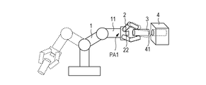
- Figs. 1A to 1C are diagrams illustrating the configuration and operation states of a robot system according to a first embodiment of the present invention.
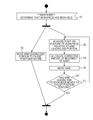
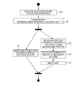
- Fig. 2 is a flowchart illustrating a control process according to the first embodiment.
- Fig. 3 is a diagram illustrating the operation state of a robot system according to a second embodiment of the present invention.
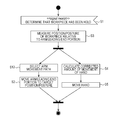
- Fig. 4 is a flowchart illustrating a control process according to the second embodiment.
- Fig. 5 is a flowchart illustrating a control process for correcting the position of a protrusion after the movement of an arm leading end portion has been completed.
- Fig. 1A to 1C are diagrams illustrating the configuration and operation states of a robot system according to a first embodiment of the present invention.
- Fig. 2 is a flowchart illustrating a control process according to the first embodiment.
- Fig. 3 is a diagram illustrating the operation state of a robot system according to a second embodiment of the present invention.
- Fig. 4 is
- FIG. 6 is a diagram illustrating the configuration and operation state of a robot system according to a third embodiment of the present invention.
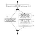
- Fig. 7 is a flowchart illustrating a control process according to the third embodiment.
- Fig. 8 is a flowchart illustrating a control process according to a fourth embodiment of the present invention.
- Fig. 9 is a flowchart illustrating a control process according to a fifth embodiment of the present invention.
- Fig. 10 is a flowchart illustrating a control process according to a sixth embodiment of the present invention.
- Fig. 11 is a flowchart illustrating a control process according to a seventh embodiment of the present invention.
- Fig. 12 is a flowchart illustrating a control process according to an eighth embodiment of the present invention.
- Fig. 1A is a diagram illustrating an exemplary configuration of a robot system according to an embodiment of the present invention.
- An arm 1 is a multi-joint serial link robot. Each joint is driven by a motor, so that the position/posture of an arm leading end portion 11 can be adjusted.
- a hand 2 is attached to the arm leading end portion 11.
- the hand 2 is provided with a holding portion (holding mechanism) 21, and can hold and release a workpiece 3 with the holding portion 21.
- the hand 2 is provided with control mechanisms for correcting the position/posture of a held object.
- control mechanisms include a rotating mechanism at a joint corresponding to a wrist and a multi-joint finger mechanism, and can also be achieved in a parallel link mechanism by combining X, Y, and Z stages and a 3-axis (pan, tilt, and roll) pan head.
- the time constant of the arm 1 is large.
- the time constant of the hand 2 is smaller than that of the arm 1. Accordingly, the hand 2 can perform high-responsivity control processing.
- the hand 2 is provided with a position/posture measurement device 22 for measuring the position/posture of the held workpiece 3 relative to the arm leading end portion 11.
- the position/posture measurement device 22 is, for example, a visual sensor including a camera and an image processing unit.
- the arm 1 and the hand 2 are controlled by a robot control device 5.
- An application control device 6 transmits an instruction to the robot control device 5 so as to operate the arm 1 and the hand 2 and can receive information about the position/posture of the workpiece 3 held by the holding portion 21 from the position/posture measurement device 22.
- An application used to perform control processing according to an embodiment of the present invention is stored in the application control device 6 for execution.
- the arm 1 is a multi-joint serial link robot and the hand 2 is a parallel link mechanism.
- the arm 1 and the hand 2 may be other mechanisms.
- FIG. 1A illustrates a state immediately after the holding portion 21 has held the workpiece 3.
- Fig. 1B illustrates a state immediately before the workpiece 3 is fitted into the hole portion 41 of the workpiece 4.
- Fig. 1B illustrates a state immediately before the workpiece 3 is fitted into the hole portion 41 of the workpiece 4.
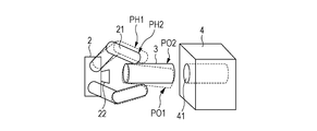
- Fig. 1C illustrates the positional relationship among the hand 2, the workpiece 3, and the workpiece 4 obtained immediately before the workpiece 3 is fitted into the hole portion 41 of the workpiece 4.
- Fig. 2 is a flowchart illustrating a control process performed by the application control device 6.
- step S1A it is determined that the holding portion 21 has held the workpiece 3 (step S1.)
- the workpiece 3 is in contact with a component supply palette or the like immediately after the workpiece 3 has been held.
- the position/posture of the workpiece 3 may be slightly changed.
- step S1 it may be determined whether the workpiece 3 has been lifted. The description of a process performed before the holding portion 21 holds the workpiece 3 is omitted.
- the target position/posture PA1 is the position/posture of the arm leading end portion 11 in a robot standard coordinate system which is obtained immediately before the holding portion 21 fits the workpiece 3 held in a normal position/posture PO2 into the hole portion 41 of the workpiece 4.
- the normal position/posture PO2 is the position/posture of the workpiece 3 relative to the arm leading end portion 11.
- a position/posture PO1 of the workpiece 3 and a position/posture PH1 and a position/posture PH2 of the hand 2, which will be described later, are also a position/posture relative to the arm leading end portion 11.
- the holding portion 21 does not always hold the workpiece 3 in the normal position/posture PO2. As represented by broken lines in Fig. 1C, when the holding portion 21 holds the workpiece 3 in the position/posture PO1 and then the workpiece 3 is subjected to a fitting operation, the workpiece 3 hits against the workpiece 4.
- steps S3 to S5 the position/posture of the workpiece 3 is measured and is corrected so that it is changed from the position/posture PO1 to the normal position/posture PO2.
- the measurement and correction of the position/posture of the workpiece 3 are performed in steps S3 to S5 while the arm leading end portion 11 moves in step S2.
- the position/posture measurement device 22 measures the position/posture PO1 of the workpiece 3 relative to the arm leading end portion 11 (step S3.)
- the target position/posture PH2 of the hand 2 when the workpiece 3 is moved to the normal position/posture PO2 is calculated on the basis of the current position/posture PH1 of the hand 2 and the position/posture PO1 of the workpiece 3 (a result of the measurement of the position/posture) (step S4.)
- the hand 2 is moved from the current position/posture PH1 to the target position/posture PH2 (step S5.)
- the measurement of the position/posture of the workpiece held by the hand relative to the arm leading end portion and the correction of the position/posture of the hand relative to the arm leading end portion are performed.
- the workpiece 3 may not be a rigid body.
- the leading end of the workpiece 3 may be a flexible protrusion 31. An operation for fitting the flexible protrusion 31 into the hole portion 41 of the workpiece 4 will be described.
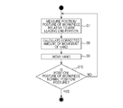
- Fig. 4 is a flowchart illustrating a control process according to the second embodiment.
- the operations of steps S1 to S5 are the same as those described with reference to Fig. 2.
- the position/posture measurement device 22 measures the position/posture of a leading end of the flexible protrusion 31 of the workpiece 3.
- step S5 it is determined whether the arm leading end portion 11 has already moved to the target position/posture PA1 (step S6.)
- step S3 the measurement of the position/posture of the flexible protrusion 31 is performed (step S3), the correction of the position/posture of the hand 2 is performed (step S4), and the movement of the hand 2 is performed (step S5.)
- Fig. 5 is a flowchart illustrating a control process for correcting the position of the flexible protrusion 31 after the movement of the arm leading end portion 11 has been completed. Operations of steps S7 to S9 are the same as those of steps S3 to S5 in Fig. 4, respectively. It is determined whether the flexible protrusion 31 is in the normal position/posture (step S10.) When the flexible protrusion 31 is in the normal position/posture, the process ends. When the flexible protrusion 31 is not in the normal position/posture, the process from steps S7 to S9 is repeated.
- the deviation of the position/posture of the workpiece 4 from the normal position/posture does not occur.
- the position/posture of the workpiece 4 may deviate from the normal position/posture.
- Fig. 6 is a diagram illustrating an exemplary configuration of a robot system according to the third embodiment.
- a position/posture measurement device 7 is disposed.
- the position/posture measurement device 7 measures the position/posture of the workpiece 4 and notifies the application control device 6 of a result of the measurement.
- the position/posture measurement device 7 is, for example, a vision sensor using a camera. Any method capable of measuring the position/posture of the workpiece 4 can be used as a method performed by the position/posture measurement device 7.
- Fig. 7 is a flowchart illustrating a control process according to the third embodiment.
- the difference between the control process illustrated in Fig. 7 and the control process illustrated in Fig. 2 is that step S11 in which the position/posture of the workpiece 4 is measured is added before step S1.
- Step S11 may be performed at any point before step S4.
- step S4 in calculation of the corrected amount of movement of the hand 2 (step S4), the target position/posture PH2 of the hand 2 at the time of movement of the workpiece 3 to the normal position/posture PO2 is calculated on the basis of the current position/posture PH1 of the hand 2 and the position/posture PO1 of the workpiece 3.
- the position/posture of the workpiece 4 is also used in the operation of step S4.
- the corrected amount of movement of the hand 2 calculated in step S4 is further corrected so that the deviation of the position/posture of the workpiece 4 from the normal position/posture is canceled.
- the corrected amount of movement of the hand 2 is obtained by subtracting PH1 from PH2 (PH2 - PH1.)
- a plurality of movement paths of the arm leading end portion 11 are determined in advance. One of these movement paths is selected in accordance with the position/posture of the workpiece 3 held by the holding portion 21.
- a simulation is performed in advance.
- a movement path on which the workpiece 3 can move without hitting against an obstacle is obtained by the simulation and is then associated with the corresponding position/posture of the workpiece 3.
- the relationship between the position/posture of the workpiece 3 and the movement path of the arm leading end portion 11 allowing the workpiece 3 to move without hitting against an obstacle is stored in the form of table.
- one of the movement paths of the arm leading end portion 11 is selected in accordance with the positions/postures of the workpiece 3.
- Fig. 8 is a flowchart illustrating a control process according to the fourth embodiment.
- the difference between the control process illustrated in Fig. 8 and the control process illustrated in Fig. 2 is that the operation of step S3 is performed before a process branching point and an operation of step S12 for selecting one of movement paths of the arm leading end portion 11 is performed before step S2.
- the position/posture of the workpiece 3 relative to the arm leading end portion 11 is measured (step S3.) Subsequently, the process branches out into two ways. In one of two ways, the movement of the arm leading end portion 11 is performed. First, one of the movement paths of the arm leading end portion 11 determined in advance is selected on the basis of the position/posture of the workpiece 3 measured in step S3 (step S12.)
- the arm leading end portion 11 is moved to the target position/posture PA1 along the selected movement path (step S2.)
- the position correction of the hand 2 is performed. Like in the control process illustrated in Fig. 2, first, the corrected amount of movement of the hand 2 is calculated (step S4.) The hand 2 is moved by the corrected amount of movement of the hand 2 (step S5.)
- a movement path of the arm leading end portion 11 is selected.
- a movement path of the hand 2 may be selected.
- Fig. 9 is a flowchart illustrating a control process according to the fifth embodiment. The difference between the control process illustrated in Fig. 9 and the control process illustrated in Fig. 2 is that an operation of step S13 for selecting a movement path of the hand 2 is performed instead of the operation of step S4. Like in the fourth embodiment, a simulation is performed so as to create a table. By referring to the table, a movement path of the hand 2 can be selected on the basis of the position/posture of the workpiece 3.
- a movement path of the arm leading end portion 11 is selected on the basis of the position/posture of the workpiece 3 held by the holding portion 21.
- the position/posture of the workpiece 4 measured by the position/posture measurement device 7 may be used for the selection of a movement path of the arm leading end portion 11.
- Fig. 10 is a flowchart illustrating a control process according to the sixth embodiment.
- the difference between the control process illustrated in Fig. 10 and the control process illustrated in Fig. 8 is that the position/posture measurement device 7 measures the position/posture of the workpiece 4 first (step S11.)
- both the position/posture of the workpiece 3 relative to the arm leading end portion 11 and the position/posture of the workpiece 4 in a robot standard coordinate system are used. More specifically, the relationship between the combination of the position/posture of the workpiece 3 and the position/posture of the workpiece 4 and the movement path of the arm leading end portion 11 allowing the workpiece 3 to move without hitting against an obstacle is obtained by simulation and is then stored in the form of table. By referring to the table, a movement path of the arm leading end portion 11 is selected.
- a movement path of the hand 2 is selected on the basis of the position/posture of the workpiece 3 held by the holding portion 21.
- the position/posture of the workpiece 4 measured by the position/posture measurement device 7 may also be used for the selection of a movement path of the hand 2.
- Fig. 11 is a flowchart illustrating a control process according to the seventh embodiment.
- the difference between the control process illustrated in Fig. 11 and the control process illustrated in Fig. 9 is that the position/posture measurement device 7 measures the position/posture of the workpiece 4 first (step S11.)
- both the position/posture of the workpiece 3 relative to the arm leading end portion 11 and the position/posture of the workpiece 4 in a robot standard coordinate system are used.
- the relationship between the combination of the position/posture of the workpiece 3 and the position/posture of the workpiece 4 and the movement path of the hand 2 allowing the workpiece 3 to move without hitting against an obstacle is obtained by simulation and is then stored in the form of table.
- a movement path of the hand 2 is selected.
- a movement path of the arm leading end portion 11 or a movement path of the hand 2 is selected.
- Fig. 12 is a flowchart illustrating a control process obtained by combining a control process according to the sixth embodiment and a control process according to the seventh embodiment.
- the difference between the control process illustrated in Fig. 12 and the control process illustrated in Fig. 10 is that the operation of step S13 for selecting a movement path of the hand 2 is performed instead of the operation of step S4.
- a time required to prevent the collision with an obstacle may be shortened.
- a table used to select a movement path of the arm leading end portion 11 and a movement path of the hand 2 is created by performing a simulation and is then stored.
- a control process according to this embodiment obtained by combining a control process according to the sixth embodiment and a control process according to the seventh embodiment has been described. However, any combination of control processes according to embodiments may be used on condition that both a movement path of the arm leading end portion 11 and a movement path of the hand 2 are selected.
- aspects of the present invention can also be realized by a computer of a system or apparatus (or devices such as a CPU or MPU) that reads out and executes a program recorded on a memory device to perform the functions of the above-described embodiment(s), and by a method, the steps of which are performed by a computer of a system or apparatus by, for example, reading out and executing a program recorded on a memory device to perform the functions of the above-described embodiment(s).
- the program is provided to the computer for example via a network or from a recording medium of various types serving as the memory device (e.g., computer-readable medium).
Landscapes
- Engineering & Computer Science (AREA)
- Robotics (AREA)
- Mechanical Engineering (AREA)
- Health & Medical Sciences (AREA)
- General Health & Medical Sciences (AREA)
- Orthopedic Medicine & Surgery (AREA)
- Physics & Mathematics (AREA)
- General Physics & Mathematics (AREA)
- Multimedia (AREA)
- Theoretical Computer Science (AREA)
- Length Measuring Devices By Optical Means (AREA)
- Manipulator (AREA)
Abstract
In a robot system including an arm capable of adjusting a position/posture of an arm leading end portion thereof, a hand that is attached to the arm leading end portion, is provided with a holding portion for holding a workpiece, and is capable of adjusting a position/posture of the workpiece held by the holding portion relative to the arm leading end portion, and a position/posture measurement device configured to measure the position/posture of the workpiece relative to the arm leading end portion, the position/posture of the workpiece is measured while the arm leading end portion moves after the holding portion has held the workpiece and the position/posture of the hand relative to the arm leading end portion is corrected on the basis of a result of the measurement so that a predetermined position/posture of the workpiece relative to the arm leading end portion is set.
Description
The present invention relates to a robot system for holding and moving a workpiece and an apparatus, a method, and a program for controlling the robot system.
For various purposes including a purpose of stably producing high-quality products and a purpose of relieving people of dangerous works and physically demanding works, industrial robots are used in production sites.
Robots having an arm and a hand for holding a workpiece which is attached to the arm have been proposed. Such a robot repeatedly performs a simple operation by moving the arm along a predetermined path and causing the hand to perform a holding operation. The simple operation is, for example, conveyance of a workpiece, rearrangement of a workpiece, or fitting or assembling of a workpiece to another workpiece.
For example, when a robot conveys a component placed at a predetermined position on a component supply palette, the robot moves an arm thereof to a position at which a hand thereof can hold the component, operates the hand to hold the component, moves the arm to convey the component to a predetermined position on a delivery palette, and operates the hand to release the component.
However, when a workpiece (the component) is not correctly disposed at the predetermined position on the component supply palette, the robot incompletely holds the workpiece and it is difficult for the robot to complete an operation (conveyance.) Japanese Patent Laid-Open No. 6-170771 discloses a method of measuring the position/posture of a workpiece with a distance detector provided at a hand immediately before the workpiece is held, adjusting the position/posture of a holding unit to the position/posture of the workpiece, and holding the workpiece.
However, even if such a method is performed, the position/posture of the workpiece may be changed on contact with the holding unit disposed at the hand when the workpiece is held by the holding unit.
In order to improve such a situation, after the workpiece has been held, the position/posture of the workpiece may be measured and corrected. Japanese Patent Laid-Open No. 2009-50921 discloses an apparatus for holding a workpiece, bringing the workpiece into contact with an object whose position/posture has been known, measuring the position/posture of the workpiece, correcting the deviation of the position/posture of the workpiece from a reference position/posture, and moving a robot on the basis of a result of the correction of the deviation. Furthermore, the apparatus disclosed in Japanese Patent Laid-Open No. 2009-50921 detects a positional deviation of the workpiece held in a hand from a reference position and controls the movement of the hand to compensate for the positional deviation.
However, since the apparatus disclosed in Japanese Patent Laid-Open No. 2009-50921 brings the held workpiece into contact with the object whose position/posture has been known when measuring the position/posture of the workpiece, a cycle time is increased.
An apparatus disclosed in Japanese Patent Laid-Open No. 2000-71190 compensates for the positional deviation of a workpiece by correcting the target position/posture of a hand on the basis of the positional deviation. In general, multi-axis control arm robots for industrial use have a large moment of inertia in an arm portion thereof so as to maintain rigidity and also have a large time constant.
In inverse kinematics calculation of a via point, the largest time constant in a normal system is used. Accordingly, in order to complete the correction of a position/posture without increasing an arm movement time, it is necessary to complete the determination of a corrected target position/posture a time corresponding to a time constant earlier than a target expected time of arrival. Thus, in order not to increase a cycle time in a system such as a multi-axis control arm robot for industrial use having a large time constant, it is necessary to reduce a time required for the measurement of a position/posture of a held workpiece and the determination of a corrected target position/posture.
In the above-described method in the related art and the above-described apparatuses in the related art, when a workpiece is fitted or assembled to another workpiece, the positional deviation of another workpiece is not corrected while the positional deviation of the workpiece is corrected.
Furthermore, in the above-described method in the related art and the above-described apparatuses in the related art, when the positional deviation of a held workpiece is large, the workpiece may hit against an obstacle while an arm moves or the holding of the workpiece may be performed again.
The present invention has been made in consideration of the above situation, and has as its object to measure and correct the position/posture of a workpiece held by a hand without increasing a cycle time.
According to the present invention, the foregoing object is attained by providing a robot system including an arm capable of adjusting a position/posture of an arm leading end portion thereof, a hand that is attached to the arm leading end portion, is provided with a holding mechanism for holding a workpiece, and is capable of adjusting a position/posture of the workpiece held by the holding mechanism relative to the arm leading end portion, a first position/posture measurement unit configured to measure the position/posture of the workpiece held by the holding mechanism relative to the arm leading end portion, and a control unit configured to perform measurement and correction of the position/posture of the workpiece held by the holding mechanism while the arm leading end portion moves after the holding mechanism has held the workpiece. In the measurement of the position/posture of the held workpiece, the control unit measures the position/posture of the workpiece relative to the arm leading end portion. In the correction of the position/posture of the held workpiece, the control unit corrects a position/posture of the hand relative to the arm leading end portion on the basis of a result of the measurement so that a predetermined position/posture of the workpiece relative to the arm leading end portion is set.
Other features and advantages of the present invention will be apparent from the following description taken in conjunction with the accompanying drawings, in which like reference characters designate the same or similar parts throughout the figures thereof.
The accompanying drawings, which are incorporated in and constitute a part of the specification, illustrate embodiments of the invention and, together with the description, serve to explain the principles of the invention.
Figs. 1A to 1C are diagrams illustrating the configuration and operation states of a robot system according to a first embodiment of the present invention.
Fig. 2 is a flowchart illustrating a control process according to the first embodiment.
Fig. 3 is a diagram illustrating the operation state of a robot system according to a second embodiment of the present invention.
Fig. 4 is a flowchart illustrating a control process according to the second embodiment.
Fig. 5 is a flowchart illustrating a control process for correcting the position of a protrusion after the movement of an arm leading end portion has been completed.
Fig. 6 is a diagram illustrating the configuration and operation state of a robot system according to a third embodiment of the present invention.
Fig. 7 is a flowchart illustrating a control process according to the third embodiment.
Fig. 8 is a flowchart illustrating a control process according to a fourth embodiment of the present invention.
Fig. 9 is a flowchart illustrating a control process according to a fifth embodiment of the present invention.
Fig. 10 is a flowchart illustrating a control process according to a sixth embodiment of the present invention.
Fig. 11 is a flowchart illustrating a control process according to a seventh embodiment of the present invention.
Fig. 12 is a flowchart illustrating a control process according to an eighth embodiment of the present invention.
Preferred embodiments of the present invention will be described in detail below with reference to the accompanying drawings.
Fig. 1A is a diagram illustrating an exemplary configuration of a robot system according to an embodiment of the present invention. An arm 1 is a multi-joint serial link robot. Each joint is driven by a motor, so that the position/posture of an arm leading end portion 11 can be adjusted.
A hand 2 is attached to the arm leading end portion 11. The hand 2 is provided with a holding portion (holding mechanism) 21, and can hold and release a workpiece 3 with the holding portion 21. In addition, the hand 2 is provided with control mechanisms for correcting the position/posture of a held object. These control mechanisms include a rotating mechanism at a joint corresponding to a wrist and a multi-joint finger mechanism, and can also be achieved in a parallel link mechanism by combining X, Y, and Z stages and a 3-axis (pan, tilt, and roll) pan head.
The time constant of the arm 1 is large. The time constant of the hand 2 is smaller than that of the arm 1. Accordingly, the hand 2 can perform high-responsivity control processing.
In addition, the hand 2 is provided with a position/posture measurement device 22 for measuring the position/posture of the held workpiece 3 relative to the arm leading end portion 11. The position/posture measurement device 22 is, for example, a visual sensor including a camera and an image processing unit.
The arm 1 and the hand 2 are controlled by a robot control device 5. An application control device 6 transmits an instruction to the robot control device 5 so as to operate the arm 1 and the hand 2 and can receive information about the position/posture of the workpiece 3 held by the holding portion 21 from the position/posture measurement device 22. An application used to perform control processing according to an embodiment of the present invention is stored in the application control device 6 for execution.
In this embodiment, the arm 1 is a multi-joint serial link robot and the hand 2 is a parallel link mechanism. However, the arm 1 and the hand 2 may be other mechanisms.
An operation for holding the workpiece 3 with the holding portion 21 and fitting the workpiece 3 into a hole portion 41 of a workpiece 4 will be described. Fig. 1A illustrates a state immediately after the holding portion 21 has held the workpiece 3. Fig. 1B illustrates a state immediately before the workpiece 3 is fitted into the hole portion 41 of the workpiece 4. In Fig. 1B, the illustration of the robot control device 5 and the application control device 6 is omitted. Fig. 1C illustrates the positional relationship among the hand 2, the workpiece 3, and the workpiece 4 obtained immediately before the workpiece 3 is fitted into the hole portion 41 of the workpiece 4.
Fig. 2 is a flowchart illustrating a control process performed by the application control device 6. As illustrated in Fig. 1A, it is determined that the holding portion 21 has held the workpiece 3 (step S1.) The workpiece 3 is in contact with a component supply palette or the like immediately after the workpiece 3 has been held. In this state, when the workpiece 3 is lifted and is apart from the component supply palette, the position/posture of the workpiece 3 may be slightly changed. When this change in the position/posture of the workpiece 3 becomes a problem, after the operation of step S1 has been performed, it may be determined whether the workpiece 3 has been lifted. The description of a process performed before the holding portion 21 holds the workpiece 3 is omitted.
Next, as illustrated in Fig. 1B, the arm leading end portion 11 is moved to a target position/posture PA1 (step S2.) The target position/posture PA1 is the position/posture of the arm leading end portion 11 in a robot standard coordinate system which is obtained immediately before the holding portion 21 fits the workpiece 3 held in a normal position/posture PO2 into the hole portion 41 of the workpiece 4. The normal position/posture PO2 is the position/posture of the workpiece 3 relative to the arm leading end portion 11. A position/posture PO1 of the workpiece 3 and a position/posture PH1 and a position/posture PH2 of the hand 2, which will be described later, are also a position/posture relative to the arm leading end portion 11.
The holding portion 21 does not always hold the workpiece 3 in the normal position/posture PO2. As represented by broken lines in Fig. 1C, when the holding portion 21 holds the workpiece 3 in the position/posture PO1 and then the workpiece 3 is subjected to a fitting operation, the workpiece 3 hits against the workpiece 4.
In steps S3 to S5, the position/posture of the workpiece 3 is measured and is corrected so that it is changed from the position/posture PO1 to the normal position/posture PO2. The measurement and correction of the position/posture of the workpiece 3 are performed in steps S3 to S5 while the arm leading end portion 11 moves in step S2. First, the position/posture measurement device 22 measures the position/posture PO1 of the workpiece 3 relative to the arm leading end portion 11 (step S3.)
The target position/posture PH2 of the hand 2 when the workpiece 3 is moved to the normal position/posture PO2 is calculated on the basis of the current position/posture PH1 of the hand 2 and the position/posture PO1 of the workpiece 3 (a result of the measurement of the position/posture) (step S4.)
The conversion from a coordinate system CO fixed on the workpiece 3 to another coordinate system will be described. It is assumed that coordinate conversion matrices corresponding to the position/posture PH1, the position/posture PH2, the position/posture PO1, and the position/posture PO2 are MHC1, MHC2, MVH1, and MVH2, respectively. Using these coordinate conversion matrices and a coordinate conversion matrix MOH between the coordinate system CO and a coordinate system fixed on the hand 2, the following equations are obtained under the assumption that the relationship between the position/posture of the holding portion 21 and the position/posture of the workpiece 3 is not changed when the holding portion 21 holds the workpiece 3.

Accordingly, the following equation is obtained.

When these conversion matrices are separated into translation components (Tx, Ty, and Tz) and rotation components (Rx, Ry, and Rz) around axes in the XYZ coordinate system, homogeneous coordinates represented by the following product of matrices are obtained. The order in which matrices are multiplied is changed in accordance with the type of a position/posture correction mechanism for the hand 2. In this embodiment, a Z axis, a Y axis, and an X axis are rotated and then translation is performed.

The hand 2 is moved from the current position/posture PH1 to the target position/posture PH2 (step S5.)
By performing the above-described control method, even if the holding portion 21 holds the workpiece 3 in any position/posture, this does not affect the movement of the arm leading end portion 11. Accordingly, it is possible to perform a fitting operation without increasing a cycle time by completing the correction of the position/posture of the workpiece 3 before the arm leading end portion 11 moves to the target position/posture PA1.
Since the correction of the position/posture of the workpiece 3 is performed after the holding portion 21 has held the workpiece 3, it is unnecessary to obtain information about the accurate position/posture of the workpiece 3 before the workpiece 3 is held. Accordingly, when a method of measuring the position/posture of the workpiece 3 before the workpiece 3 is held is used, it is unnecessary to accurately measure the position/posture of the workpiece 3.
As described previously, while the arm leading end portion moves, the measurement of the position/posture of the workpiece held by the hand relative to the arm leading end portion and the correction of the position/posture of the hand relative to the arm leading end portion are performed. As a result, it is possible to perform the measurement and correction of the position/posture of the workpiece held by the hand without increasing a cycle time. Furthermore, it is possible to increase a time required to measure the position/posture of the held workpiece 3 and determine a corrected target position/posture of the hand 2 in a system having a large time constant. Still furthermore, it is unnecessary to accurately measure the position/posture of the workpiece 3 before the workpiece 3 is held.
The workpiece 3 may not be a rigid body. For example, as illustrated in Fig. 3, the leading end of the workpiece 3 may be a flexible protrusion 31. An operation for fitting the flexible protrusion 31 into the hole portion 41 of the workpiece 4 will be described.
Fig. 4 is a flowchart illustrating a control process according to the second embodiment. The operations of steps S1 to S5 are the same as those described with reference to Fig. 2. In this case, however, the position/posture measurement device 22 measures the position/posture of a leading end of the flexible protrusion 31 of the workpiece 3.
After the process from steps S1 to S5 has been performed, the leading end of the flexible protrusion 31 is not necessarily in the normal position/posture because the flexible protrusion 31 deforms under its own weight. Accordingly, after the operation of step S5 has been performed, it is determined whether the arm leading end portion 11 has already moved to the target position/posture PA1 (step S6.) When it is determined that the arm leading end portion 11 is moving, the measurement of the position/posture of the flexible protrusion 31 is performed (step S3), the correction of the position/posture of the hand 2 is performed (step S4), and the movement of the hand 2 is performed (step S5.)
By performing the above-described control process, even if the flexible protrusion 31 is not in the normal position/posture after the movement of the arm leading end portion 11 has been completed, it can be expected that the deviation from the normal position/posture is small. It is therefore possible to complete the position correction of the flexible protrusion 31 in a short time after the movement of the arm has been completed.
Fig. 5 is a flowchart illustrating a control process for correcting the position of the flexible protrusion 31 after the movement of the arm leading end portion 11 has been completed. Operations of steps S7 to S9 are the same as those of steps S3 to S5 in Fig. 4, respectively. It is determined whether the flexible protrusion 31 is in the normal position/posture (step S10.) When the flexible protrusion 31 is in the normal position/posture, the process ends. When the flexible protrusion 31 is not in the normal position/posture, the process from steps S7 to S9 is repeated.
As described previously, by repeatedly performing the measurement and correction of a position/posture while the arm leading end portion 11 moves, even if a deformable flexible workpiece is assembled to another workpiece, it is possible to appropriately correct the position/posture of the deformable flexible workpiece.
In the above-described embodiments, the deviation of the position/posture of the workpiece 4 from the normal position/posture does not occur. However, like the workpiece 3, the position/posture of the workpiece 4 may deviate from the normal position/posture.
Accordingly, a control process is performed in consideration of the deviation of the position/posture of the workpiece 4. Fig. 6 is a diagram illustrating an exemplary configuration of a robot system according to the third embodiment. In addition to the components illustrated in Fig. 1, a position/posture measurement device 7 is disposed. The position/posture measurement device 7 measures the position/posture of the workpiece 4 and notifies the application control device 6 of a result of the measurement. The position/posture measurement device 7 is, for example, a vision sensor using a camera. Any method capable of measuring the position/posture of the workpiece 4 can be used as a method performed by the position/posture measurement device 7.
Fig. 7 is a flowchart illustrating a control process according to the third embodiment. The difference between the control process illustrated in Fig. 7 and the control process illustrated in Fig. 2 is that step S11 in which the position/posture of the workpiece 4 is measured is added before step S1.
The operation of Step S11 may be performed at any point before step S4.
In the control process illustrated in Fig. 2, in calculation of the corrected amount of movement of the hand 2 (step S4), the target position/posture PH2 of the hand 2 at the time of movement of the workpiece 3 to the normal position/posture PO2 is calculated on the basis of the current position/posture PH1 of the hand 2 and the position/posture PO1 of the workpiece 3. In this embodiment, the position/posture of the workpiece 4 is also used in the operation of step S4.
More specifically, the corrected amount of movement of the hand 2 calculated in step S4 is further corrected so that the deviation of the position/posture of the workpiece 4 from the normal position/posture is canceled. For example, when the position/posture PH1 and the position/posture PH2 are represented with six elements, that is, the amounts of translation in the X, Y, and Z directions and the amounts of rotation about axes, the corrected amount of movement of the hand 2 is obtained by subtracting PH1 from PH2 (PH2 - PH1.)
By performing the above-described control process, it is possible to correct the positional deviation of the workpiece 4 when a workpiece is fitted or assembled to the workpiece 4. The third embodiment has been described on the basis of the first embodiment. However, correction processing similar to the above-described correction processing according to the third embodiment may be performed when the corrected amount of movement of the hand 2 is calculated in step S4 illustrated in Fig. 4 and step S8 illustrated in Fig. 5.
While the arm leading end portion 11 moves after the holding portion 21 has held the workpiece 3, the workpiece 3 may hit against an obstacle. Accordingly, in order to prevent the collision, a plurality of movement paths of the arm leading end portion 11 are determined in advance. One of these movement paths is selected in accordance with the position/posture of the workpiece 3 held by the holding portion 21.
For example, in order to determine the movement paths of the arm leading end portion 11, a simulation is performed in advance. A movement path on which the workpiece 3 can move without hitting against an obstacle is obtained by the simulation and is then associated with the corresponding position/posture of the workpiece 3. More specifically, the relationship between the position/posture of the workpiece 3 and the movement path of the arm leading end portion 11 allowing the workpiece 3 to move without hitting against an obstacle is stored in the form of table. By referring to the table created at the time of the simulation, one of the movement paths of the arm leading end portion 11 is selected in accordance with the positions/postures of the workpiece 3.
Fig. 8 is a flowchart illustrating a control process according to the fourth embodiment. The difference between the control process illustrated in Fig. 8 and the control process illustrated in Fig. 2 is that the operation of step S3 is performed before a process branching point and an operation of step S12 for selecting one of movement paths of the arm leading end portion 11 is performed before step S2.
The position/posture of the workpiece 3 relative to the arm leading end portion 11 is measured (step S3.) Subsequently, the process branches out into two ways. In one of two ways, the movement of the arm leading end portion 11 is performed. First, one of the movement paths of the arm leading end portion 11 determined in advance is selected on the basis of the position/posture of the workpiece 3 measured in step S3 (step S12.)
The arm leading end portion 11 is moved to the target position/posture PA1 along the selected movement path (step S2.)
In parallel to the movement of the arm leading end portion 11, in the other one of two ways, the position correction of the hand 2 is performed. Like in the control process illustrated in Fig. 2, first, the corrected amount of movement of the hand 2 is calculated (step S4.) The hand 2 is moved by the corrected amount of movement of the hand 2 (step S5.)
By performing the above-described control process, when the deviation of the position/posture of a held workpiece is large, it is possible to prevent the held workpiece from hitting against an obstacle during movement of the arm leading end portion 11 or to avoid the need to perform a holding operation again.
In the fourth embodiment, in order to prevent the workpiece 3 from hitting against an obstacle, a movement path of the arm leading end portion 11 is selected. However, a movement path of the hand 2 may be selected. Fig. 9 is a flowchart illustrating a control process according to the fifth embodiment. The difference between the control process illustrated in Fig. 9 and the control process illustrated in Fig. 2 is that an operation of step S13 for selecting a movement path of the hand 2 is performed instead of the operation of step S4. Like in the fourth embodiment, a simulation is performed so as to create a table. By referring to the table, a movement path of the hand 2 can be selected on the basis of the position/posture of the workpiece 3.
In the fourth embodiment, in order to prevent the workpiece 3 from hitting against an obstacle, a movement path of the arm leading end portion 11 is selected on the basis of the position/posture of the workpiece 3 held by the holding portion 21. However, the position/posture of the workpiece 4 measured by the position/posture measurement device 7 may be used for the selection of a movement path of the arm leading end portion 11.
Fig. 10 is a flowchart illustrating a control process according to the sixth embodiment. The difference between the control process illustrated in Fig. 10 and the control process illustrated in Fig. 8 is that the position/posture measurement device 7 measures the position/posture of the workpiece 4 first (step S11.)
When a movement path of the arm leading end portion 11 is selected (step S12), both the position/posture of the workpiece 3 relative to the arm leading end portion 11 and the position/posture of the workpiece 4 in a robot standard coordinate system are used. More specifically, the relationship between the combination of the position/posture of the workpiece 3 and the position/posture of the workpiece 4 and the movement path of the arm leading end portion 11 allowing the workpiece 3 to move without hitting against an obstacle is obtained by simulation and is then stored in the form of table. By referring to the table, a movement path of the arm leading end portion 11 is selected.
In the fifth embodiment, in order to prevent the workpiece 3 from hitting against an obstacle, a movement path of the hand 2 is selected on the basis of the position/posture of the workpiece 3 held by the holding portion 21. However, the position/posture of the workpiece 4 measured by the position/posture measurement device 7 may also be used for the selection of a movement path of the hand 2.
Fig. 11 is a flowchart illustrating a control process according to the seventh embodiment. The difference between the control process illustrated in Fig. 11 and the control process illustrated in Fig. 9 is that the position/posture measurement device 7 measures the position/posture of the workpiece 4 first (step S11.)
When a movement path of the hand 2 is selected (step S13), both the position/posture of the workpiece 3 relative to the arm leading end portion 11 and the position/posture of the workpiece 4 in a robot standard coordinate system are used. As described previously, the relationship between the combination of the position/posture of the workpiece 3 and the position/posture of the workpiece 4 and the movement path of the hand 2 allowing the workpiece 3 to move without hitting against an obstacle is obtained by simulation and is then stored in the form of table. By referring to the table, a movement path of the hand 2 is selected.
In the fourth to seventh embodiments, a movement path of the arm leading end portion 11 or a movement path of the hand 2 is selected. However, both of them may be selected. Fig. 12 is a flowchart illustrating a control process obtained by combining a control process according to the sixth embodiment and a control process according to the seventh embodiment. The difference between the control process illustrated in Fig. 12 and the control process illustrated in Fig. 10 is that the operation of step S13 for selecting a movement path of the hand 2 is performed instead of the operation of step S4. By selecting both a movement path of the arm leading end portion 11 and a movement path of the hand 2, as compared with a case in which either a movement path of the arm leading end portion 11 or a movement path of the hand 2 is used to prevent collision with an obstacle, a time required to prevent the collision with an obstacle may be shortened.
As described previously, a table used to select a movement path of the arm leading end portion 11 and a movement path of the hand 2 is created by performing a simulation and is then stored. A control process according to this embodiment obtained by combining a control process according to the sixth embodiment and a control process according to the seventh embodiment has been described. However, any combination of control processes according to embodiments may be used on condition that both a movement path of the arm leading end portion 11 and a movement path of the hand 2 are selected.
Aspects of the present invention can also be realized by a computer of a system or apparatus (or devices such as a CPU or MPU) that reads out and executes a program recorded on a memory device to perform the functions of the above-described embodiment(s), and by a method, the steps of which are performed by a computer of a system or apparatus by, for example, reading out and executing a program recorded on a memory device to perform the functions of the above-described embodiment(s). For this purpose, the program is provided to the computer for example via a network or from a recording medium of various types serving as the memory device (e.g., computer-readable medium).
While the present invention has been described with reference to exemplary embodiments, it is to be understood that the invention is not limited to the disclosed exemplary embodiments. The scope of the following claims is to be accorded the broadest interpretation so as to encompass all such modifications and equivalent structures and functions.
This application claims the benefit of Japanese Patent Application No. 2009-289614, filed December 21, 2009, which is hereby incorporated by reference herein in its entirety.
Claims (11)
- A robot system comprising:
an arm capable of adjusting a position/posture of an arm leading end portion thereof;
a hand that is attached to the arm leading end portion, is provided with a holding mechanism for holding a workpiece, and is capable of adjusting a position/posture of the workpiece held by the holding mechanism relative to the arm leading end portion;
a first position/posture measurement unit configured to measure the position/posture of the workpiece held by the holding mechanism relative to the arm leading end portion; and
a control unit configured to perform measurement and correction of the position/posture of the workpiece held by the holding mechanism while the arm leading end portion moves after the holding mechanism has held the workpiece, and
wherein, in the measurement of the position/posture of the held workpiece, the control unit measures the position/posture of the workpiece relative to the arm leading end portion, and
wherein, in the correction of the position/posture of the held workpiece, the control unit corrects a position/posture of the hand relative to the arm leading end portion on the basis of a result of the measurement so that a predetermined position/posture of the workpiece relative to the arm leading end portion is set. - The robot system according to Claim 1, wherein the control unit completes the measurement and correction of the position/posture of the held workpiece before movement of the arm leading end portion is completed.
- The robot system according to Claim 1, wherein the control unit repeatedly performs the measurement and correction of the position/posture of the held workpiece while the arm leading end portion moves.
- The robot system according to Claim 1, further comprising a second position/posture measurement unit configured to measure a position/posture of another workpiece when the held workpiece is fitted or assembled to the other workpiece, and
wherein the control unit determines the predetermined position/posture of the workpiece relative to the arm leading end portion on the basis of both a result of measurement of the position/posture of the workpiece performed by the first position/posture measurement unit and a result of measurement of the position/posture of the other workpiece performed by the second position/posture measurement unit. - The robot system according to Claim 1, wherein the control unit selects a movement path of the arm leading end portion from among a plurality of movement paths determined in advance on the basis of a result of measurement of the position/posture of the held workpiece.
- The robot system according to Claim 1, wherein, in the correction of the position/posture of the held workpiece, the control unit selects a movement path of the workpiece from among a plurality of movement paths determined in advance on the basis of a result of measurement of the position/posture of the held workpiece.
- The robot system according to Claim 1, further comprising a second position/posture measurement unit configured to measure a position/posture of another workpiece when the held workpiece is fitted or assembled to the other workpiece, and
wherein the control unit selects a movement path of the arm leading end portion from among a plurality of movement paths determined in advance on the basis of both a result of measurement of the position/posture of the held workpiece and a result of measurement of the position/posture of the other workpiece performed by the second position/posture measurement unit. - The robot system according to Claim 1, further comprising a second position/posture measurement unit configured to measure a position/posture of another workpiece when the held workpiece is fitted or assembled to the other workpiece, and
wherein the control unit selects a movement path of the workpiece from among a plurality of movement paths determined in advance on the basis of both a result of measurement of the position/posture of the held workpiece and a result of measurement of the position/posture of the other workpiece performed by the second position/posture measurement unit. - A control apparatus for a robot system including an arm capable of adjusting a position/posture of an arm leading end portion thereof, a hand that is attached to the arm leading end portion, is provided with a holding mechanism for holding a workpiece, and is capable of adjusting a position/posture of the workpiece held by the holding mechanism relative to the arm leading end portion, and a position/posture measurement unit configured to measure the position/posture of the workpiece held by the holding mechanism relative to the arm leading end portion, the control apparatus comprising a control unit configured to perform measurement and correction of the position/posture of the workpiece held by the holding mechanism while the arm leading end portion moves after the holding mechanism has held the workpiece, and
wherein, in the measurement of the position/posture of the held workpiece, the control unit measures the position/posture of the workpiece relative to the arm leading end portion, and
wherein, in the correction of the position/posture of the held workpiece, the control unit corrects a position/posture of the hand relative to the arm leading end portion on the basis of a result of the measurement so that a predetermined position/posture of the workpiece relative to the arm leading end portion is set. - A control method for a robot system including an arm capable of adjusting a position/posture of an arm leading end portion thereof, a hand that is attached to the arm leading end portion, is provided with a holding mechanism for holding a workpiece, and is capable of adjusting a position/posture of the workpiece held by the holding mechanism relative to the arm leading end portion, and a position/posture measurement unit configured to measure the position/posture of the workpiece held by the holding mechanism relative to the arm leading end portion, the control method comprising a controlling step of performing measurement and correction of the position/posture of the workpiece held by the holding mechanism while the arm leading end portion moves after the holding mechanism has held the workpiece, and
wherein, in the measurement of the position/posture of the held workpiece, the position/posture of the workpiece relative to the arm leading end portion is measured, and
wherein, in the correction of the position/posture of the held workpiece, a position/posture of the hand relative to the arm leading end portion is corrected on the basis of a result of the measurement so that a predetermined position/posture of the workpiece relative to the arm leading end portion is set. - A program for controlling a robot system including an arm capable of adjusting a position/posture of an arm leading end portion thereof, a hand that is attached to the arm leading end portion, is provided with a holding mechanism for holding a workpiece, and is capable of adjusting a position/posture of the workpiece held by the holding mechanism relative to the arm leading end portion, and a position/posture measurement unit configured to measure the position/posture of the workpiece held by the holding mechanism relative to the arm leading end portion, the program causing a computer to execute control processing for performing measurement and correction of the position/posture of the workpiece held by the holding mechanism while the arm leading end portion moves after the holding mechanism has held the workpiece, and
wherein, in the measurement of the position/posture of the held workpiece, the position/posture of the workpiece relative to the arm leading end portion is measured, and
wherein, in the correction of the position/posture of the held workpiece, a position/posture of the hand relative to the arm leading end portion is corrected on the basis of a result of the measurement so that a predetermined position/posture of the workpiece relative to the arm leading end portion is set.
Priority Applications (1)
| Application Number | Priority Date | Filing Date | Title |
|---|---|---|---|
| US13/517,218 US9418291B2 (en) | 2009-12-21 | 2010-12-20 | Information processing apparatus, information processing method, and computer-readable storage medium |
Applications Claiming Priority (2)
| Application Number | Priority Date | Filing Date | Title |
|---|---|---|---|
| JP2009289614A JP5578844B2 (en) | 2009-12-21 | 2009-12-21 | Information processing apparatus, information processing method, and program |
| JP2009-289614 | 2009-12-21 |
Publications (1)
| Publication Number | Publication Date |
|---|---|
| WO2011077693A1 true WO2011077693A1 (en) | 2011-06-30 |
Family
ID=43709035
Family Applications (1)
| Application Number | Title | Priority Date | Filing Date |
|---|---|---|---|
| PCT/JP2010/007367 Ceased WO2011077693A1 (en) | 2009-12-21 | 2010-12-20 | Robot system for reorienting a held workpiece |
Country Status (3)
| Country | Link |
|---|---|
| US (1) | US9418291B2 (en) |
| JP (1) | JP5578844B2 (en) |
| WO (1) | WO2011077693A1 (en) |
Cited By (7)
| Publication number | Priority date | Publication date | Assignee | Title |
|---|---|---|---|---|
| CN103037188A (en) * | 2011-09-30 | 2013-04-10 | 吴小平 | Projector special for crosswise splicing and cinema projecting apparatus formed by the same |
| CN104044152A (en) * | 2013-03-15 | 2014-09-17 | 株式会社安川电机 | Robot system, method for controlling robot, and method for producing to-be-processed material |
| CN105965505A (en) * | 2015-03-13 | 2016-09-28 | 佳能株式会社 | Robot controlling method, robot apparatus, program and recording medium |
| WO2019059790A1 (en) * | 2017-09-22 | 2019-03-28 | Rma Spółka Z Ograniczoną Odpowiedzialnością | Method and device for automatic planing of a tube face using a robot, particularly in a process of manufacturing of tubular heat exchangers |
| US11057608B2 (en) | 2016-01-04 | 2021-07-06 | Qualcomm Incorporated | Depth map generation in structured light system |
| WO2025017351A1 (en) * | 2023-07-18 | 2025-01-23 | Abb Schweiz Ag | Precise placement based on on-the-fly object pose estimation |
| US12600039B2 (en) * | 2023-03-30 | 2026-04-14 | Kawasaki Jukogyo Kabushiki Kaisha | Robot, conveying system, and robot-controlling method |
Families Citing this family (20)
| Publication number | Priority date | Publication date | Assignee | Title |
|---|---|---|---|---|
| US8531650B2 (en) | 2008-07-08 | 2013-09-10 | Chiaro Technologies LLC | Multiple channel locating |
| JP6023415B2 (en) | 2011-10-17 | 2016-11-09 | キヤノン株式会社 | Three-dimensional measuring apparatus, control method and program for three-dimensional measuring apparatus |
| US9217636B2 (en) | 2012-06-11 | 2015-12-22 | Canon Kabushiki Kaisha | Information processing apparatus, information processing method, and a computer-readable storage medium |
| JP6101134B2 (en) | 2013-04-01 | 2017-03-22 | キヤノン株式会社 | Information processing apparatus and information processing method |
| JP6144976B2 (en) * | 2013-06-26 | 2017-06-07 | キヤノン株式会社 | Information processing apparatus, assembly apparatus, information processing method, and program |
| US9562760B2 (en) | 2014-03-10 | 2017-02-07 | Cognex Corporation | Spatially self-similar patterned illumination for depth imaging |
| JP6516453B2 (en) * | 2014-11-26 | 2019-05-22 | 株式会社ミツトヨ | Image measuring device and measuring device |
| TWI503518B (en) * | 2014-12-29 | 2015-10-11 | Pixart Imaging Inc | Distance measuring method and device |
| JP2016178393A (en) * | 2015-03-19 | 2016-10-06 | 株式会社リコー | Projection system, projector, information processing apparatus and program |
| US10571668B2 (en) * | 2015-05-09 | 2020-02-25 | Cognex Corporation | Catadioptric projector systems, devices, and methods |
| JP6570321B2 (en) * | 2015-06-02 | 2019-09-04 | キヤノン株式会社 | Information processing apparatus, information processing method, and program |
| CN105945953A (en) * | 2016-06-17 | 2016-09-21 | 小船信息科技(上海)有限公司 | Visual identification system for robot |
| JP6480902B2 (en) * | 2016-10-06 | 2019-03-13 | ファナック株式会社 | Projection pattern creation device and three-dimensional measurement device |
| US10699429B2 (en) | 2017-08-19 | 2020-06-30 | Cognex Corporation | Coding distance topologies for structured light patterns for 3D reconstruction |
| CN109635619B (en) | 2017-08-19 | 2021-08-31 | 康耐视公司 | Encoding distance topology of structured light patterns for three-dimensional reconstruction |
| JP2019047311A (en) * | 2017-09-01 | 2019-03-22 | セイコーエプソン株式会社 | Image projection system and control method thereof |
| US11507097B2 (en) * | 2018-02-05 | 2022-11-22 | Pixart Imaging Inc. | Control apparatus for auto clean machine and auto clean machine control method |
| ES2968482T3 (en) * | 2018-02-28 | 2024-05-09 | Dwfritz Automation Inc | Device and activation management method for measuring equipment |
| CN111208827B (en) * | 2020-02-20 | 2020-09-08 | 崔永亮 | Projection type AGV two-dimensional code navigation system and application thereof |
| JP2024168264A (en) * | 2023-05-23 | 2024-12-05 | 株式会社レゾナック | Surface profile measuring device and surface profile measuring method |
Citations (9)
| Publication number | Priority date | Publication date | Assignee | Title |
|---|---|---|---|---|
| JPH06170771A (en) | 1992-11-30 | 1994-06-21 | Mitsubishi Electric Corp | Industrial robot device |
| JP2000071190A (en) | 1998-08-27 | 2000-03-07 | Komatsu Ltd | Work transfer system |
| US6141863A (en) * | 1996-10-24 | 2000-11-07 | Fanuc Ltd. | Force-controlled robot system with visual sensor for performing fitting operation |
| EP1391275A2 (en) * | 2002-08-23 | 2004-02-25 | Fanuc Ltd | Object handling apparatus |
| EP1449626A1 (en) * | 2003-02-19 | 2004-08-25 | Fanuc Ltd | Workpiece conveying apparatus with visual sensor for checking the gripping state |
| WO2008047872A1 (en) * | 2006-10-20 | 2008-04-24 | Hitachi, Ltd. | Manipulator |
| JP2008279549A (en) * | 2007-05-10 | 2008-11-20 | Honda Motor Co Ltd | Work transfer system and work transfer method |
| JP2009050921A (en) | 2007-08-23 | 2009-03-12 | Fanuc Ltd | Handling device |
| JP2009289614A (en) | 2008-05-29 | 2009-12-10 | Toshiba Corp | Gas-blast circuit-breaker |
Family Cites Families (26)
| Publication number | Priority date | Publication date | Assignee | Title |
|---|---|---|---|---|
| US5065992A (en) | 1990-06-07 | 1991-11-19 | Roll Systems, Inc. | Method for processing web material |
| US5138821A (en) | 1991-10-10 | 1992-08-18 | Roll Systems, Inc. | High speed inserter fed from roll material |
| JPH07101181A (en) | 1993-10-06 | 1995-04-18 | Taiyo Ltd | Bookbinding |
| JP2874710B2 (en) | 1996-02-26 | 1999-03-24 | 日本電気株式会社 | 3D position measuring device |
| BR9709679A (en) * | 1996-06-13 | 2000-01-11 | Leuven K U Res & Dev | System and process for achieving a three-dimensional description. |
| JPH1062140A (en) | 1996-08-14 | 1998-03-06 | Oki Electric Ind Co Ltd | Method and device for reconstruction of shape |
| JP3621215B2 (en) * | 1996-12-03 | 2005-02-16 | パイオニア株式会社 | 3D measuring device |
| EP1102211A3 (en) | 1999-11-19 | 2006-09-13 | Matsushita Electric Industrial Co., Ltd. | Image processor, method of providing image processing services and order processing method |
| JP2001356010A (en) * | 2000-06-12 | 2001-12-26 | Asahi Hightech Kk | Three-dimensional shape measuring apparatus |
| US7106885B2 (en) * | 2000-09-08 | 2006-09-12 | Carecord Technologies, Inc. | Method and apparatus for subject physical position and security determination |
| JP3895238B2 (en) | 2002-08-28 | 2007-03-22 | 株式会社東芝 | Obstacle detection apparatus and method |
| US20070165243A1 (en) * | 2004-02-09 | 2007-07-19 | Cheol-Gwon Kang | Device for measuring 3d shape using irregular pattern and method for the same |
| JP4604774B2 (en) * | 2005-03-14 | 2011-01-05 | オムロン株式会社 | Calibration method for 3D measurement |
| US8054471B2 (en) | 2006-09-15 | 2011-11-08 | Sciammarella Cesar A | System and method for analyzing displacements and contouring of surfaces |
| JP2008145121A (en) * | 2006-12-06 | 2008-06-26 | Nikon Corp | 3D shape measuring device |
| JP2008224540A (en) * | 2007-03-14 | 2008-09-25 | Car Mate Mfg Co Ltd | Distortion inspection method and inspection apparatus |
| JP2009031150A (en) | 2007-07-27 | 2009-02-12 | Omron Corp | Three-dimensional shape measuring apparatus, three-dimensional shape measuring method, three-dimensional shape measuring program, and recording medium |
| JP4341723B2 (en) * | 2008-02-22 | 2009-10-07 | パナソニック電工株式会社 | Light projection device, lighting device |
| JP5317169B2 (en) | 2008-06-13 | 2013-10-16 | 洋 川崎 | Image processing apparatus, image processing method, and program |
| WO2010015086A1 (en) | 2008-08-06 | 2010-02-11 | Creaform Inc. | System for adaptive three-dimensional scanning of surface characteristics |
| JP5583761B2 (en) * | 2009-06-01 | 2014-09-03 | ホスラー ゲルト | 3D surface detection method and apparatus using dynamic reference frame |
| KR20110018696A (en) | 2009-08-18 | 2011-02-24 | 주식회사 이턴 | Apparatus and method for processing 3d image |
| JP5631025B2 (en) * | 2010-03-10 | 2014-11-26 | キヤノン株式会社 | Information processing apparatus, processing method thereof, and program |
| EP2622576A4 (en) | 2010-10-01 | 2017-11-08 | Saab AB | Method and apparatus for solving position and orientation from correlated point features in images |
| US9182221B2 (en) | 2011-06-13 | 2015-11-10 | Canon Kabushiki Kaisha | Information processing apparatus and information processing method |
| US9217636B2 (en) | 2012-06-11 | 2015-12-22 | Canon Kabushiki Kaisha | Information processing apparatus, information processing method, and a computer-readable storage medium |
-
2009
- 2009-12-21 JP JP2009289614A patent/JP5578844B2/en not_active Expired - Fee Related
-
2010
- 2010-12-20 WO PCT/JP2010/007367 patent/WO2011077693A1/en not_active Ceased
- 2010-12-20 US US13/517,218 patent/US9418291B2/en active Active
Patent Citations (9)
| Publication number | Priority date | Publication date | Assignee | Title |
|---|---|---|---|---|
| JPH06170771A (en) | 1992-11-30 | 1994-06-21 | Mitsubishi Electric Corp | Industrial robot device |
| US6141863A (en) * | 1996-10-24 | 2000-11-07 | Fanuc Ltd. | Force-controlled robot system with visual sensor for performing fitting operation |
| JP2000071190A (en) | 1998-08-27 | 2000-03-07 | Komatsu Ltd | Work transfer system |
| EP1391275A2 (en) * | 2002-08-23 | 2004-02-25 | Fanuc Ltd | Object handling apparatus |
| EP1449626A1 (en) * | 2003-02-19 | 2004-08-25 | Fanuc Ltd | Workpiece conveying apparatus with visual sensor for checking the gripping state |
| WO2008047872A1 (en) * | 2006-10-20 | 2008-04-24 | Hitachi, Ltd. | Manipulator |
| JP2008279549A (en) * | 2007-05-10 | 2008-11-20 | Honda Motor Co Ltd | Work transfer system and work transfer method |
| JP2009050921A (en) | 2007-08-23 | 2009-03-12 | Fanuc Ltd | Handling device |
| JP2009289614A (en) | 2008-05-29 | 2009-12-10 | Toshiba Corp | Gas-blast circuit-breaker |
Cited By (10)
| Publication number | Priority date | Publication date | Assignee | Title |
|---|---|---|---|---|
| CN103037188A (en) * | 2011-09-30 | 2013-04-10 | 吴小平 | Projector special for crosswise splicing and cinema projecting apparatus formed by the same |
| CN104044152A (en) * | 2013-03-15 | 2014-09-17 | 株式会社安川电机 | Robot system, method for controlling robot, and method for producing to-be-processed material |
| EP2783805A3 (en) * | 2013-03-15 | 2015-04-22 | Kabushiki Kaisha Yaskawa Denki | Robot system, method for controlling robot, and method for producing to-be-processed material |
| CN105965505A (en) * | 2015-03-13 | 2016-09-28 | 佳能株式会社 | Robot controlling method, robot apparatus, program and recording medium |
| US10144132B2 (en) | 2015-03-13 | 2018-12-04 | Canon Kabushiki Kaisha | Robot controlling method, robot apparatus, program and recording medium |
| CN105965505B (en) * | 2015-03-13 | 2019-04-05 | 佳能株式会社 | Robot control method, robot device, program and recording medium |
| US11057608B2 (en) | 2016-01-04 | 2021-07-06 | Qualcomm Incorporated | Depth map generation in structured light system |
| WO2019059790A1 (en) * | 2017-09-22 | 2019-03-28 | Rma Spółka Z Ograniczoną Odpowiedzialnością | Method and device for automatic planing of a tube face using a robot, particularly in a process of manufacturing of tubular heat exchangers |
| US12600039B2 (en) * | 2023-03-30 | 2026-04-14 | Kawasaki Jukogyo Kabushiki Kaisha | Robot, conveying system, and robot-controlling method |
| WO2025017351A1 (en) * | 2023-07-18 | 2025-01-23 | Abb Schweiz Ag | Precise placement based on on-the-fly object pose estimation |
Also Published As
| Publication number | Publication date |
|---|---|
| US9418291B2 (en) | 2016-08-16 |
| US20130108104A1 (en) | 2013-05-02 |
| JP2011128117A (en) | 2011-06-30 |
| JP5578844B2 (en) | 2014-08-27 |
Similar Documents
| Publication | Publication Date | Title |
|---|---|---|
| WO2011077693A1 (en) | Robot system for reorienting a held workpiece | |
| US9043023B2 (en) | Robot system, and control apparatus and method thereof | |
| CN108214454B (en) | Robot system, robot control device, and robot control method | |
| US11285609B2 (en) | Working position correcting method and working robot | |
| US9969088B2 (en) | Force sensor correcting method | |
| JP6108860B2 (en) | Robot system and control method of robot system | |
| JP6468741B2 (en) | Robot system and robot system calibration method | |
| CN108994876B (en) | Teaching position correction device and teaching position correction method | |
| US9519736B2 (en) | Data generation device for vision sensor and detection simulation system | |
| US20160279800A1 (en) | Robot, robot control device, and robotic system | |
| JP6039382B2 (en) | Robot system and control method of robot system | |
| JP2015182144A (en) | Robot system and calibration method of robot system | |
| US20040266276A1 (en) | Connector gripping device, connector inspection system comprising the device, and connector connection system | |
| EP4101604A1 (en) | System and method for improving accuracy of 3d eye-to-hand coordination of a robotic system | |
| JP2011115877A (en) | Double arm robot | |
| CN116940451B (en) | Robotic systems and workpiece supply methods | |
| JP6153316B2 (en) | Robot system and control method of robot system | |
| JP5618770B2 (en) | Robot calibration apparatus and calibration method | |
| JP2004001122A (en) | Picking device | |
| CN105313127A (en) | Robot, control method of robot, and control device of robot | |
| JP2010058256A (en) | Arm position regulating method and apparatus and robot system | |
| US11833687B2 (en) | Robot apparatus, control method for the robot apparatus, assembly method using the robot apparatus, and recording medium | |
| US8761936B2 (en) | Teaching line correcting apparatus, teaching line correcting method, and program thereof | |
| JP2007011978A (en) | Robot motion control device | |
| WO2022195944A1 (en) | Robot system, and control method for robot system |
Legal Events
| Date | Code | Title | Description |
|---|---|---|---|
| 121 | Ep: the epo has been informed by wipo that ep was designated in this application |
Ref document number: 10807491 Country of ref document: EP Kind code of ref document: A1 |
|
| NENP | Non-entry into the national phase |
Ref country code: DE |
|
| 122 | Ep: pct application non-entry in european phase |
Ref document number: 10807491 Country of ref document: EP Kind code of ref document: A1 |
|
| WWE | Wipo information: entry into national phase |
Ref document number: 13517218 Country of ref document: US |