WO2011074385A1 - 移動通信システム、基地局、移動局、および無線通信方法 - Google Patents
移動通信システム、基地局、移動局、および無線通信方法 Download PDFInfo
- Publication number
- WO2011074385A1 WO2011074385A1 PCT/JP2010/070897 JP2010070897W WO2011074385A1 WO 2011074385 A1 WO2011074385 A1 WO 2011074385A1 JP 2010070897 W JP2010070897 W JP 2010070897W WO 2011074385 A1 WO2011074385 A1 WO 2011074385A1
- Authority
- WO
- WIPO (PCT)
- Prior art keywords
- channel
- base station
- radio
- mobile station
- mobile
- Prior art date
- Legal status (The legal status is an assumption and is not a legal conclusion. Google has not performed a legal analysis and makes no representation as to the accuracy of the status listed.)
- Ceased
Links
Images


Classifications
-
- H—ELECTRICITY
- H04—ELECTRIC COMMUNICATION TECHNIQUE
- H04W—WIRELESS COMMUNICATION NETWORKS
- H04W72/00—Local resource management
- H04W72/20—Control channels or signalling for resource management
- H04W72/23—Control channels or signalling for resource management in the downlink direction of a wireless link, i.e. towards a terminal
-
- H—ELECTRICITY
- H04—ELECTRIC COMMUNICATION TECHNIQUE
- H04L—TRANSMISSION OF DIGITAL INFORMATION, e.g. TELEGRAPHIC COMMUNICATION
- H04L5/00—Arrangements affording multiple use of the transmission path
- H04L5/0001—Arrangements for dividing the transmission path
- H04L5/0003—Two-dimensional division
- H04L5/0005—Time-frequency
- H04L5/0007—Time-frequency the frequencies being orthogonal, e.g. OFDM(A) or DMT
-
- H—ELECTRICITY
- H04—ELECTRIC COMMUNICATION TECHNIQUE
- H04L—TRANSMISSION OF DIGITAL INFORMATION, e.g. TELEGRAPHIC COMMUNICATION
- H04L5/00—Arrangements affording multiple use of the transmission path
- H04L5/003—Arrangements for allocating sub-channels of the transmission path
-
- H—ELECTRICITY
- H04—ELECTRIC COMMUNICATION TECHNIQUE
- H04L—TRANSMISSION OF DIGITAL INFORMATION, e.g. TELEGRAPHIC COMMUNICATION
- H04L5/00—Arrangements affording multiple use of the transmission path
- H04L5/003—Arrangements for allocating sub-channels of the transmission path
- H04L5/0078—Timing of allocation
- H04L5/0082—Timing of allocation at predetermined intervals
-
- H—ELECTRICITY
- H04—ELECTRIC COMMUNICATION TECHNIQUE
- H04W—WIRELESS COMMUNICATION NETWORKS
- H04W72/00—Local resource management
- H04W72/50—Allocation or scheduling criteria for wireless resources
- H04W72/51—Allocation or scheduling criteria for wireless resources based on terminal or device properties
-
- H—ELECTRICITY
- H04—ELECTRIC COMMUNICATION TECHNIQUE
- H04W—WIRELESS COMMUNICATION NETWORKS
- H04W72/00—Local resource management
- H04W72/50—Allocation or scheduling criteria for wireless resources
- H04W72/54—Allocation or scheduling criteria for wireless resources based on quality criteria
Definitions
- the present invention relates to a mobile communication system, a base station, a mobile station, and a wireless communication method.
- Some mobile communication systems allow a base station to change a radio channel assigned to a mobile station for each frame.
- the base station transmits uplink connection information (a radio channel assigned in an uplink frame) so that each mobile station can use a shared channel separately for each frame. ) For transmitting an uplink map message and a downlink map message for notifying downlink connection information (a radio channel assigned in a downlink frame) to a mobile station every frame.
- the base station must notify the mobile station of the radio channel to be assigned to the mobile station every frame. For this reason, a part of the radio resource must be allocated every frame for notification of the radio channel.
- the present invention has been made in view of the above problems, and an object thereof is to provide a mobile communication system, a base station, a mobile station, and a channel allocation method that can reduce radio resources required for radio channel notification. To do.
- a mobile communication system is a mobile communication system including a base station and a mobile station that perform communication via at least a part of a plurality of radio channels, and the base station A channel allocating unit for allocating a radio channel having an allocation effective period of two frames or more to the mobile station, and a new channel allocating unit by the channel allocating unit in response to expiration of an allocation effective period of the radio channel allocated by the channel allocating unit.
- Channel notification means for notifying the mobile station of a radio channel assigned to the mobile station, wherein the mobile station uses the radio channel notified from the base station until the effective period of the radio channel expires. It includes a wireless communication means used for communication with a station.
- the frequency of notification of the radio channel from the base station to the mobile station is reduced by providing an allocation valid period of 2 frames or more for the radio channel allocated to the mobile station. For this reason, according to the present invention, it is possible to reduce radio resources required for radio channel notification.
- each of the plurality of radio channels belongs to one of a plurality of time slots defined by a time division multiple access method
- the radio communication unit transmits a radio channel from the base station. Stops receiving radio signals transmitted from the base station in time slots other than the time slot to which the radio channel belongs, after the next frame of the notified frame, until the validity period of the notified radio channel expires To do.
- the power consumption of the mobile station can be reduced.
- the base station determines an effective period for determining an allocation effective period of a radio channel to be allocated by the channel allocating unit based on information on the quality of communication between the base station and the mobile station.
- the channel notifying unit notifies the mobile station of the radio channel allocated by the channel allocating unit and the allocation effective period of the radio channel determined by the effective period determining unit.
- the radio channel allocation effective period changes according to the quality of communication between the base station and the mobile station, communication throughput can be improved.
- the information related to the quality of communication between the base station and the mobile station includes the reception quality of a radio signal transmitted from the mobile station and received by the base station.
- the information related to the quality of communication between the base station and the mobile station includes a moving speed of the mobile station.
- the information related to the quality of communication between the base station and the mobile station includes the total number of mobile stations connected to the base station.
- the base station according to the present invention is a base station that communicates with a mobile station via at least a part of a plurality of radio channels, and allocates a radio channel having an allocation validity period of two frames or more to the mobile station.
- Channel allocating means, and channel notifying means for notifying the mobile station of a radio channel newly allocated by the channel allocating means in response to expiration of an effective period of allocation of the radio channel allocated by the channel allocating means. It is characterized by including.
- the mobile station according to the present invention is a mobile station that communicates with a base station via at least a part of a plurality of radio channels, and allocates a radio channel having an allocation validity period of two frames or more to the mobile station.
- Channel allocating means, and channel notifying means for notifying the mobile station of a radio channel newly allocated by the channel allocating means in response to expiration of an effective period of allocation of the radio channel allocated by the channel allocating means.
- the wireless channel notified from the included base station is used for communication with the base station until an effective lifetime of the wireless channel expires.
- the wireless communication method is a wireless communication method in which the first and second communication devices communicate with each other via at least a part of a plurality of wireless channels. Allocating a radio channel having an allocation validity period equal to or greater than a frame to the second communication apparatus, and the first communication apparatus upon expiration of an allocation validity period of the radio channel allocated to the second communication apparatus. In response, the step of notifying the second communication device of a radio channel newly assigned to the second communication device, and the second communication device notifying the radio channel notified from the first communication device. And a step of using for communication with the first communication device until the effective period of allocation of the radio channel expires.
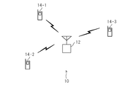
- FIG. 1 is a diagram showing a configuration of a mobile communication system 10 according to an embodiment of the present invention.
- the mobile communication system 10 includes a base station 12 and a plurality of mobile stations 14 (only mobile stations 14-1 to 14-3 are shown here).
- Each base station 12 uses an OFDMA (Orthogonal Frequency Division Multiple Access) method and a TDMA / TDD (Time Division Multiple Access / Time Division Duplex: time division multiple access / time division duplex) method.
- Wireless communication with the mobile station 14 located in the cell Examples of the mobile station 14 include a mobile phone, a communication card, and a portable information terminal with a built-in communication function.
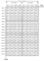
- FIG. 2 is a diagram showing a radio channel configuration in the mobile communication system 10 (horizontal axis: time, vertical axis: frequency).
- a TDMA frame having a predetermined period here, 5 ms
- each subframe is divided into a plurality of time slots (here, Slot 1 to Slot 4).
- a plurality of OFDMA subchannels here, Sch1 to Sch18 are defined in a predetermined frequency band.
- PRU Physical Resource Unit
- Each PRU belongs to one of the time slots (Slot 1 to Slot 4) and one of the sub-channels (Sch 1 to Sch 18).
- Slot 1 to Slot 4 The minimum unit of the radio channel that the base station 12 assigns to the mobile station 14.
- 72 PRUs are determined to be identified by consecutive PRU numbers (1, 2, 3,...) Starting from 1, for example. PRUs having the same PRU number are used in upper and lower pairs. That is, PRUs are assigned symmetrically.
- a PRU belonging to a specific subchannel is defined as a CCH (Common Channel) shared by one or more mobile stations 14.
- the base station 12 is assigned with CCH transmission / reception timing (hereinafter simply referred to as “CCH timing”) that is repeated at a predetermined cycle and does not overlap with the neighboring base stations. Specifically, any one of 80 time slot pairs (4 pairs of upper and lower time slots ⁇ 20 frames) included in 20 consecutive frames is assigned to the base station 12 as CCH timing.
- the base station 12 transmits / receives various control signals to / from one or more mobile stations 14 located in the cell of the own station at every 100 ms at the CCH timing assigned to the own station.
- ICHs Intelligent Channels individually assigned to the mobile stations 14.
- An ICH is assigned to each mobile station 14 in principle as an individual control channel and is mainly used for transmission of control information.
- An ICH (Anchor Channel) is assigned to each mobile station 14 as one or more communication channels. There are EXCH (Extra Channel) used for transmission.
- the PRU assigned as an ANCH (individual control channel) is notified from the base station 12 to the mobile station 14 at the start of communication (may be changed during communication).
- the PRU allocated as EXCH (one of the communication channels) is channel allocation information called MAP indicating whether or not 72 PRUs are allocated (for example, PRU allocated as EXCH is “1”, allocated as EXCH).
- the base station 12 notifies the mobile station 14 of a non-PRU with a 72-bit bitmap indicated by “0”.
- the base station 12 transmits a MAP to the mobile station 14 via the ANCH.
- the MAP transmission frequency (PRU notification frequency) from the base station 12 to the mobile station 14 is set by providing an allocation valid period of 2 frames or more for the PRU allocated to the mobile station 14 as EXCH.
- the radio resources required for PRU notification can be reduced.
- the mobile station 14 after the frame following the frame in which the PRU for EXCH is notified from the base station 12 (the frame that has received the MAP from the base station 12), until the effective period for the allocation of the PRU for EXCH expires, Reception of radio signals transmitted from the base station 12 may be stopped in time slots other than the time slot to which the EXCH PRU belongs. In this way, the mobile station 14 does not always need to receive a radio signal in all downlink slots, so that power consumption can be reduced.
- FIG. 3 is a functional block diagram of the base station 12.
- the base station 12 includes an antenna 20, a radio communication unit 22, a modem unit 24, and a control unit 26 (communication quality related information acquisition unit 28, channel allocation unit 30, valid period determination unit 32, channel notification. Part 34).
- the antenna 20 receives a radio signal transmitted from the mobile station 14 and outputs the received radio signal to the radio communication unit 22. Further, the antenna 20 transmits a radio signal supplied from the radio communication unit 22 to the mobile station 14.
- the wireless communication unit 22 includes a low noise amplifier, a power amplifier, a frequency converter, a band pass filter, an A / D converter, and a D / A converter.
- the radio communication unit 22 amplifies the radio signal input from the antenna 20 with a low noise amplifier, and then down-converts the radio signal to an intermediate frequency signal.
- the wireless communication unit 22 converts the intermediate frequency signal into a digital signal and then outputs the digital signal to the modem unit 24.
- the wireless communication unit 22 converts the digital signal input from the modem unit 24 into an analog signal, and then up-converts the digital signal into a wireless signal.
- the wireless communication unit 22 amplifies the wireless signal to a transmission output level with a power amplifier and then supplies the amplified signal to the antenna 20.
- the modem unit 24 includes an FFT (Fast Fourier Transform) unit, an IFFT (Inverse Fast Fourier Transform) unit, a serial-parallel converter, a parallel-serial converter, and an error detection unit.
- the modem unit 24 converts the digital signal input from the wireless communication unit 22 from serial to parallel, removes GI (Guard Interval), primary demodulation (fast Fourier transform), parallel-serial conversion, secondary demodulation (symbol demapping). , Decoding, error detection, etc.
- the modem unit 24 outputs the obtained received data to the control unit 26 and an upper layer (not shown).
- the modem unit 24 adds error detection codes, encodes, primary modulation (symbol mapping), serial-parallel conversion, secondary modulation to transmission data addressed to the mobile station 14 input from the control unit 26 and higher layers. (Inverse Fast Fourier Transform), GI addition, parallel serial conversion, etc. are performed.
- the modem unit 24 outputs the obtained digital signal to the wireless communication unit 22.
- the control unit 26 includes, for example, a CPU and a program that controls the operation of the CPU, and controls each unit of the base station 12.
- the control unit 26 functionally includes a communication quality related information acquisition unit 28, a channel allocation unit 30, a validity period determination unit 32, and a channel notification unit 34, and performs allocation and notification of PRUs to the mobile station 14. .
- the communication quality related information acquisition unit 28 acquires information regarding the quality of communication between the base station 12 and the mobile station 14.
- Information related to the quality of communication between the base station 12 and the mobile station 14 includes the reception quality of radio signals transmitted from the mobile station 14 and received by the base station 12, and transmitted and received between the base station 12 and the mobile station 14.
- the amount of communication data, the moving speed of the mobile station 14, the total number of mobile stations 14 connected to the base station 12, and the like are included.
- the reception quality of a radio signal transmitted from the mobile station 14 and received by the base station 12 includes RSSI (Received Signal Strength Strength), SINR (Signal Signal to Interference Noise and Noise Noise Ratio: signal to interference and noise power. Ratio) and FER (Frame Error Rate). These reception qualities can be acquired based on a complex symbol sequence obtained by primary demodulation (fast Fourier transform) in the modem unit 24, an error detection result in the modem unit 24, and the like.
- the moving speed of the mobile station 14 can be estimated from the propagation delay time of the radio signal transmitted from the mobile station 14. Since the radio signal transmitted from the mobile station 14 includes a training symbol (known signal) for frame synchronization, the propagation delay time of the radio signal is a complex symbol obtained by primary demodulation in the modem unit 24. It can be obtained based on the correlation value between the column and the training symbol.
- the propagation delay time of the radio signal is a complex symbol obtained by primary demodulation in the modem unit 24. It can be obtained based on the correlation value between the column and the training symbol.
- the channel allocating unit 30 is configured as a mobile station as an ANCH (individual control channel) or an EXCH (communication channel) based on the information regarding the communication quality between the base station 12 and the mobile station 14 acquired by the communication quality related information acquiring unit 28. 14 to be assigned to PRU. For example, when the base station 12 starts communication with the mobile station 14, the channel allocation unit 30 sets the PRU having the lowest RSSI among the PRUs (free PRUs) not allocated to any mobile station 14 as the mobile station. 14 is assigned. Further, the channel allocation unit 30 sets one or more PRUs as EXCH based on the SINR of the radio signal transmitted from the mobile station 14 or the amount of communication data transmitted / received between the base station 12 and the mobile station 14. Assign to the mobile station 14.
- the valid period determining unit 32 determines the PRU allocation valid period (hereinafter referred to as “MAP valid period”) that is allocated as EXCH by the channel allocating unit 30.
- the MAP valid period determined here may be a fixed value of 2 frames or more that is not changed during communication, or a variable value of 1 frame or more that can be changed during communication (it is not always necessary to be 2 frames or more).
- the validity period determining unit 32 sets the MAP validity period to a fixed value or a variable value (including a fixed value if the value is a fixed value)
- the base station 12 matches the CCH timing at the start of communication or CCH timing. May be notified to the mobile station 14.
- the validity period determination unit 32 determines the MAP validity based on the information regarding the communication quality between the base station 12 and the mobile station 14 acquired by the communication quality related information acquisition unit 28. The period may be determined. For example, the validity period determination unit 32 may increase the MAP validity period as the reception quality of a radio signal transmitted from the mobile station 14 and received by the base station 12 is higher. In addition, the validity period determination unit 32 may extend the MAP validity period as the moving speed of the mobile station 14 decreases. In addition, the validity period determination unit 32 may extend the MAP validity period as the total number of mobile stations 14 connected to the base station 12 decreases. By doing this, the MAP valid period changes according to the quality of communication between the base station 12 and the mobile station 14, and thus the communication throughput can be improved.
- the channel notification unit 34 generates a predetermined channel notification message so as to notify the mobile station 14 of the PRU allocated as ANCH or EXCH by the channel allocation unit 30, and outputs it to the modem unit 24. For example, when the base station 12 starts communication with the mobile station 14, the channel notification unit 34 generates a message including a PRU number indicating a PRU assigned as an ANCH and transmits the message to the mobile station 14. Further, the channel notification unit 34 generates a message including a MAP indicating PRU allocated as EXCH, and intermittently transmits the message to the mobile station 14.
- the channel notification unit 34 when the MAP validity period is a fixed value, the channel notification unit 34 generates a message including a new MAP in response to the expiration of the MAP validity period, and transmits the message to the mobile station 14 via the ANCH.
- the channel notification unit 34 sends a message including the new MAP and the validity period of the MAP according to the expiration of the validity period of the MAP transmitted to the mobile station 14 immediately before. It is generated and transmitted to the mobile station 14 via the ANCH.
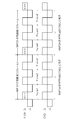
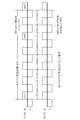
- FIG. 4 is a diagram illustrating an example of the MAP validity period and the MAP transmission timing.
- the MAP valid period is fixed to 3 frames.
- the validity period of MAP1 transmitted in the downlink (downlink subframe) of Frame1 is from the downlink of Frame1 to the uplink (uplink subframe) of Frame3.
- a new MAP2 is transmitted on the downlink of Frame4.
- a new MAP 3 is transmitted on the downlink of Frame 7.
- FIG. 5 is a diagram illustrating another example of the MAP valid period and the transmission timing of the MAP.
- the MAP effective period is variable
- the effective period of MAP1 is 4 frames
- the effective period of MAP2 that follows is 2 frames.
- the validity period of MAP1 transmitted in the downlink (downlink subframe) of Frame1 is from the downlink of Frame1 to the uplink (uplink subframe) of Frame4.
- new MAP2 is transmitted on the downlink of Frame5.
- a new MAP 3 is transmitted on the downlink of Frame 7.
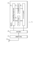
- FIG. 6 is a functional block diagram of the mobile station 14.
- the mobile station 14 includes an antenna 40, a wireless communication unit 42, a modem unit 44, and a control unit 46 (message analysis unit 48, channel allocation control unit 50).
- the antenna 40 receives a radio signal transmitted from the base station 12 and outputs the received radio signal to the radio communication unit 42.
- the antenna 40 transmits a radio signal supplied from the radio communication unit 42 to the base station 12.
- the wireless communication unit 42 includes a low noise amplifier, a power amplifier, a frequency converter, a band pass filter, an A / D converter, and a D / A converter.
- the radio communication unit 42 amplifies a radio signal input from the antenna 40 with a low noise amplifier, and then down-converts the radio signal to an intermediate frequency signal.
- the wireless communication unit 42 converts the intermediate frequency signal into a digital signal and then outputs the digital signal to the modem unit 44.
- the wireless communication unit 42 converts the digital signal input from the modulation / demodulation unit 44 into an analog signal and then up-converts the digital signal into a wireless signal.
- the radio communication unit 42 amplifies the radio signal to a transmission output level with a power amplifier and then supplies the radio signal to the antenna 40.
- the modem unit 44 includes an FFT unit, an IFFT unit, a serial-parallel converter, a parallel-serial converter, and an error detection unit.
- the modem unit 44 converts the digital signal input from the wireless communication unit 42 into serial-parallel conversion, GI removal, primary demodulation (fast Fourier transform), parallel-serial conversion, secondary demodulation (symbol demapping), decoding, and error. Perform detection.
- the modem unit 44 outputs the obtained received data to the control unit 46 and an upper layer (not shown).
- the modem unit 44 also adds error detection code, encoding, primary modulation (symbol mapping), serial-parallel conversion, secondary modulation to transmission data addressed to the base station 12 input from the control unit 46 and higher layers. (Inverse Fast Fourier Transform), GI addition, parallel serial conversion, etc. are performed.
- the modem unit 44 outputs the obtained digital signal to the wireless communication unit 42.
- the control unit 46 includes, for example, a CPU and a program that controls the operation of the CPU, and controls each unit of the mobile station 14.
- the control unit 46 functionally includes a message analysis unit 48 and a channel allocation control unit 50, and controls use of PRUs allocated from the base station 12, reception timing of radio signals transmitted from the base station 12, and the like. .
- the message analysis unit 48 extracts various messages from the base station 12 from the received data input from the modem unit 44, and analyzes the contents of the messages. For example, the message analysis unit 48 acquires a message including a PRU number indicating a PRU assigned as an ANCH from the base station 12 from the received data. The message analysis unit 48 outputs the PRU number included in the message to the channel assignment control unit 50. In addition, the message analysis unit 48 acquires a message including a MAP indicating a PRU allocated as EXCH from the base station 12 and a validity period of the MAP from the received data. The message analysis unit 48 outputs the MAP included in the message and the validity period of the MAP to the channel assignment control unit 50.
- the channel assignment control unit 50 controls the use of the PRU assigned from the base station 12 to the mobile station 14 as ANCH or EXCH based on the information input from the message analysis unit 48. For example, the channel allocation control unit 50 controls the radio communication unit 42 and the modem unit 44 so as to transmit / receive control information to / from the base station 12 via the PRU for ANCH indicated by the PRU number input from the message analysis unit 48. . Further, the channel allocation control unit 50 controls the radio communication unit 42 and the modem unit 44 so as to transmit / receive communication data to / from the base station 12 via the EXCH PRU indicated by the MAP input from the message analysis unit 48.
- MAP1 is input from the message analysis unit 48 to the channel assignment control unit 50 at the downlink timing of Frame1.
- the channel allocation control unit 50 uses the EXCH PRU indicated by the MAP1 for communication with the base station 12 until the uplink of Frame3 when the validity period of the MAP1 expires. 44.
- MAP2 is newly input from the message analysis unit 48 at the downlink timing of Frame 4
- the channel allocation control unit 50 uses the EXCH indicated by the MAP 2 until the uplink of Frame 6 where the validity period of MAP 2 expires.
- the wireless communication unit 42 and the modem unit 44 are instructed to use the PRU for communication with the base station 12.
- the valid period (4 frames) of MAP1 and MAP1 is input from the message analysis unit 48 to the channel allocation control unit 50 at the downlink timing of Frame1.
- the channel allocation control unit 50 uses the radio communication unit 42 and the modulation / demodulation unit so that the EXCH PRU indicated by the MAP 1 is used for communication with the base station 12 until the uplink of Frame 4 where the validity period of the MAP 1 expires. 44.
- the channel assignment control unit 50 determines that the validity period of MAP2 expires.
- the wireless communication unit 42 and the modem unit 44 are instructed to use the PRU for EXCH indicated by the MAP 2 for communication with the base station 12.
- the channel allocation control unit 50 starts the MAP after the frame that received the MAP from the base station 12 (the frame in which the EXCH PRU is notified from the base station 12) until the validity period of the MAP expires.
- the radio communication unit 42 may stop receiving the radio signal transmitted from the base station 12. For example, in the example illustrated in FIG. 4, when the PRU for EXCH indicated by MAP1 is arranged at the position illustrated in FIG. 7, the wireless communication unit 42 performs downlink Slots 3 and 4 for Frame 2 and Slot 3 for downlink of Frame 3. , 4 (time slot to which the EXCH PRU does not belong), reception of radio signals transmitted from the base station 12 may be stopped.
- the mobile station 14 does not need to always receive radio signals in all downlink slots (since it is not necessary to operate the radio communication unit 42 in downlink slots that do not require reception), the power consumption can be reduced. it can.
- the PCH for EXCH indicated by MAP1 cannot be known in advance, so that the radio communication unit 42 is connected from the base station 12 in all downlink slots (Slot1 to Slot4). It is necessary to receive a radio signal to be transmitted.
- the MAP transmission frequency (PRU) from the base station 12 to the mobile station 14 is determined.
- the radio resources required for PRU notification can be reduced.
- the base station 12 can transmit more user data to the mobile station 14 using, for example, vacant radio resources.
- the present invention is not limited to the above embodiment.
- transmission of a MAP from a base station to a mobile station is merely an example of a radio channel notification method, and other notification methods may be adopted. Further, the configuration of the radio channel may be different from the configuration of the radio channel shown in FIG.
- the present invention is not limited to a mobile communication system that employs the OFDMA scheme and the TDMA / TDD scheme, and is a general wireless communication system in which the first and second communication apparatuses communicate via at least a part of a plurality of wireless channels. It is applicable to.
Landscapes
- Engineering & Computer Science (AREA)
- Signal Processing (AREA)
- Computer Networks & Wireless Communication (AREA)
- Mobile Radio Communication Systems (AREA)
Abstract
Description
Claims (9)
- 複数の無線チャネルの少なくとも一部を介して通信を行う基地局と移動局とを含む移動通信システムであって、
前記基地局は、
2フレーム以上の割り当て有効期間を有する無線チャネルを前記移動局に割り当てるチャネル割当手段と、
前記チャネル割当手段により割り当てられていた無線チャネルの割り当て有効期間の満了に応じて、前記チャネル割当手段により新たに割り当てられる無線チャネルを前記移動局に通知するチャネル通知手段と、
を含み、
前記移動局は、前記基地局から通知される無線チャネルを、該無線チャネルの割り当て有効期間が満了するまで、前記基地局との通信に使用する無線通信手段を含む、
ことを特徴とする移動通信システム。 - 請求項1に記載の移動通信システムにおいて、
前記複数の無線チャネルのそれぞれは、時分割多元接続方式で規定される複数のタイムスロットのいずれかに属し、
前記無線通信手段は、前記基地局から無線チャネルが通知されたフレームの次フレーム以降、該通知された無線チャネルの割り当て有効期間が満了するまで、該無線チャネルが属するタイムスロットを除くタイムスロットにおいて、前記基地局から送信される無線信号の受信を停止する、
ことを特徴とする移動通信システム。 - 請求項1に記載の移動通信システムにおいて、
前記基地局は、当該基地局と前記移動局との通信の品質に関する情報に基づいて、前記チャネル割当手段により割り当てられる無線チャネルの割り当て有効期間を決定する有効期間決定手段をさらに含み、
前記チャネル通知手段は、前記チャネル割当手段により割り当てられる無線チャネルと、前記有効期間決定手段により決定される該無線チャネルの割り当て有効期間と、を前記移動局に通知する、
ことを特徴とする移動通信システム。 - 請求項3に記載の移動通信システムにおいて、
前記基地局と前記移動局との通信の品質に関する情報は、前記移動局から送信され前記基地局により受信される無線信号の受信品質を含む、
ことを特徴とする移動通信システム。 - 請求項3に記載の移動通信システムにおいて、
前記基地局と前記移動局との通信の品質に関する情報は、前記移動局の移動速度を含む、
ことを特徴とする移動通信システム。 - 請求項3に記載の移動通信システムにおいて、
前記基地局と前記移動局との通信の品質に関する情報は、前記基地局に接続している移動局の総数を含む、
ことを特徴とする移動通信システム。 - 複数の無線チャネルの少なくとも一部を介して移動局と通信を行う基地局であって、
2フレーム以上の割り当て有効期間を有する無線チャネルを前記移動局に割り当てるチャネル割当手段と、
前記チャネル割当手段により割り当てられていた無線チャネルの割り当て有効期間の満了に応じて、前記チャネル割当手段により新たに割り当てられる無線チャネルを前記移動局に通知するチャネル通知手段と、
を含むことを特徴とする基地局。 - 複数の無線チャネルの少なくとも一部を介して基地局と通信を行う移動局であって、
2フレーム以上の割り当て有効期間を有する無線チャネルを当該移動局に割り当てるチャネル割当手段と、
前記チャネル割当手段により割り当てられていた無線チャネルの割り当て有効期間の満了に応じて、前記チャネル割当手段により新たに割り当てられる無線チャネルを当該移動局に通知するチャネル通知手段と、
を含む前記基地局から通知される無線チャネルを、該無線チャネルの割り当て有効期間が満了するまで、前記基地局との通信に使用する、
ことを特徴とする移動局。 - 複数の無線チャネルの少なくとも一部を介して第1および第2の通信装置が通信を行う無線通信方法であって、
前記第1の通信装置が、2フレーム以上の割り当て有効期間を有する無線チャネルを前記第2の通信装置に割り当てるステップと、
前記第1の通信装置が、前記第2の通信装置に割り当てられていた無線チャネルの割り当て有効期間の満了に応じて、前記第2の通信装置に新たに割り当てられる無線チャネルを前記第2の通信装置に通知するステップと、
前記第2の通信装置が、前記第1の通信装置から通知される無線チャネルを、該無線チャネルの割り当て有効期間が満了するまで、前記第1の通信装置との通信に使用するステップと、
を含むことを特徴とする無線通信方法。
Priority Applications (2)
| Application Number | Priority Date | Filing Date | Title |
|---|---|---|---|
| CN2010800568679A CN102656935A (zh) | 2009-12-14 | 2010-11-24 | 移动通信系统、基站、移动站及无线通信方法 |
| US13/515,800 US9119194B2 (en) | 2009-12-14 | 2010-11-24 | Mobile communication system, base station, mobile station, and wireless communication method |
Applications Claiming Priority (2)
| Application Number | Priority Date | Filing Date | Title |
|---|---|---|---|
| JP2009-283299 | 2009-12-14 | ||
| JP2009283299A JP2011124942A (ja) | 2009-12-14 | 2009-12-14 | 移動通信システム、基地局、移動局、および無線通信方法 |
Publications (1)
| Publication Number | Publication Date |
|---|---|
| WO2011074385A1 true WO2011074385A1 (ja) | 2011-06-23 |
Family
ID=44167148
Family Applications (1)
| Application Number | Title | Priority Date | Filing Date |
|---|---|---|---|
| PCT/JP2010/070897 Ceased WO2011074385A1 (ja) | 2009-12-14 | 2010-11-24 | 移動通信システム、基地局、移動局、および無線通信方法 |
Country Status (4)
| Country | Link |
|---|---|
| US (1) | US9119194B2 (ja) |
| JP (1) | JP2011124942A (ja) |
| CN (1) | CN102656935A (ja) |
| WO (1) | WO2011074385A1 (ja) |
Families Citing this family (2)
| Publication number | Priority date | Publication date | Assignee | Title |
|---|---|---|---|---|
| US20160029232A1 (en) | 2014-07-22 | 2016-01-28 | Qualcomm Incorporated | Ultra reliable link design |
| CN105657836B (zh) | 2014-11-14 | 2021-09-14 | 索尼公司 | 用于移动基站的物理小区标识分配的设备和方法 |
Citations (2)
| Publication number | Priority date | Publication date | Assignee | Title |
|---|---|---|---|---|
| JPH1079970A (ja) * | 1996-09-02 | 1998-03-24 | Nippon Telegr & Teleph Corp <Ntt> | 無線パケットチャネル割当方法 |
| JP2009290339A (ja) * | 2008-05-27 | 2009-12-10 | Kyocera Corp | 基地局および無線通信方法 |
Family Cites Families (8)
| Publication number | Priority date | Publication date | Assignee | Title |
|---|---|---|---|---|
| CN1092454C (zh) * | 1994-02-04 | 2002-10-09 | Ntt移动通信网株式会社 | 一种移动通信系统及其中的无线电信道分配方法 |
| KR20000022672A (ko) | 1998-09-07 | 2000-04-25 | 마츠시타 덴끼 산교 가부시키가이샤 | 이동국 통신 장치, 기지국 통신 장치 및 무선 통신 방법 |
| CN1549474A (zh) | 2003-05-19 | 2004-11-24 | �ʼҷ����ֵ��ӹɷ�����˾ | 在tdd cdma通信体系中支持p2p通信的方法和装置 |
| KR100891806B1 (ko) * | 2003-11-26 | 2009-04-07 | 삼성전자주식회사 | 직교 주파수 분할 다중 접속 시스템에서 적응적 채널할당을 위한 채널 상태 추정 장치 및 방법 |
| KR100810290B1 (ko) | 2004-12-14 | 2008-03-07 | 삼성전자주식회사 | 무선 통신 시스템에서 데이터 버스트 할당 방법 및 시스템 |
| WO2007052649A1 (ja) * | 2005-10-31 | 2007-05-10 | Sharp Kabushiki Kaisha | 無線送信機、無線通信システム及び無線送信方法 |
| US8050683B2 (en) * | 2006-12-27 | 2011-11-01 | Alcatel Lucent | Method of determining when a mobile station is ready to be served during a handoff in a wireless communications network |
| JP5122309B2 (ja) | 2008-01-29 | 2013-01-16 | 京セラ株式会社 | 通信方法およびそれを利用した端末装置 |
-
2009
- 2009-12-14 JP JP2009283299A patent/JP2011124942A/ja active Pending
-
2010
- 2010-11-24 US US13/515,800 patent/US9119194B2/en not_active Expired - Fee Related
- 2010-11-24 CN CN2010800568679A patent/CN102656935A/zh active Pending
- 2010-11-24 WO PCT/JP2010/070897 patent/WO2011074385A1/ja not_active Ceased
Patent Citations (2)
| Publication number | Priority date | Publication date | Assignee | Title |
|---|---|---|---|---|
| JPH1079970A (ja) * | 1996-09-02 | 1998-03-24 | Nippon Telegr & Teleph Corp <Ntt> | 無線パケットチャネル割当方法 |
| JP2009290339A (ja) * | 2008-05-27 | 2009-12-10 | Kyocera Corp | 基地局および無線通信方法 |
Also Published As
| Publication number | Publication date |
|---|---|
| US9119194B2 (en) | 2015-08-25 |
| JP2011124942A (ja) | 2011-06-23 |
| US20120307812A1 (en) | 2012-12-06 |
| CN102656935A (zh) | 2012-09-05 |
Similar Documents
| Publication | Publication Date | Title |
|---|---|---|
| US11310798B2 (en) | Measurement method and apparatus for supporting mobility in communication system | |
| JP7070983B2 (ja) | 無線通信システムにおいて制御情報をマッピングするための方法及び装置 | |
| KR101567370B1 (ko) | 광대역 무선통신 시스템에서 협력적 송수신 장치 및 방법 | |
| EP1806884B1 (en) | Method and system for transmitting/receiving data in a communication system | |
| RU2595271C2 (ru) | Вставка виртуальной несущей в традиционную основную несущую ofdm в системе связи | |
| US20200068610A1 (en) | Resource scheduling method, network device, and communications device | |
| CN112737758B (zh) | 信息发送、接收方法及设备 | |
| CN113395146B (zh) | 一种信息传输方法、电子设备及计算机可读存储介质 | |
| EP3696994A1 (en) | Multi-access scheme and signal structure for d2d communications | |
| CN104919880B (zh) | 用于基于信道条件的测量为机器类型通信选择虚拟载波的移动通信终端设备和方法 | |
| CN104144501B (zh) | D2d发现信号资源配置方法、系统及相关装置 | |
| KR20190004347A (ko) | 리소스 스케줄링 방법 및 장치 | |
| US9668250B2 (en) | Wireless communication system, master communication device, slave communication device, and channel allocation information notification method | |
| CN106664684A (zh) | 用于d2d通信的d2d数据资源的决定方法和装置 | |
| JPWO2016002855A1 (ja) | 基地局装置および端末装置 | |
| JP2017152752A (ja) | 端末装置、および基地局装置 | |
| JP2009010659A (ja) | 基地局装置及びユーザ装置並びにリファレンスシグナル系列の割り当て方法 | |
| CN116846720A (zh) | 用于指示数字基本配置的方法和设备 | |
| US9520974B2 (en) | Interference measurement method and apparatus for new carrier type | |
| WO2011074385A1 (ja) | 移動通信システム、基地局、移動局、および無線通信方法 | |
| US8824425B2 (en) | Base station device and communication control method for base station device | |
| KR20200100001A (ko) | 통신 시스템에서 이동성 지원을 위한 측정 방법 및 장치 | |
| CN121795064A (zh) | 用于配置用于sbfd操作的资源的方法和装置 | |
| CN106716965A (zh) | 用于进行直连通信的方法和装置 | |
| KR20150007220A (ko) | Lte d2d 통신에서의 주파수 관리 시스템 및 방법 |
Legal Events
| Date | Code | Title | Description |
|---|---|---|---|
| WWE | Wipo information: entry into national phase |
Ref document number: 201080056867.9 Country of ref document: CN |
|
| 121 | Ep: the epo has been informed by wipo that ep was designated in this application |
Ref document number: 10837414 Country of ref document: EP Kind code of ref document: A1 |
|
| 121 | Ep: the epo has been informed by wipo that ep was designated in this application |
Ref document number: 10837414 Country of ref document: EP Kind code of ref document: A1 |
|
| NENP | Non-entry into the national phase |
Ref country code: DE |
|
| WWE | Wipo information: entry into national phase |
Ref document number: 13515800 Country of ref document: US |
|
| 122 | Ep: pct application non-entry in european phase |
Ref document number: 10837414 Country of ref document: EP Kind code of ref document: A1 |