WO2011074082A1 - Magnetic-resonant-coupling power transmission apparatus and magnetic-resonant-coupling power reception apparatus - Google Patents
Magnetic-resonant-coupling power transmission apparatus and magnetic-resonant-coupling power reception apparatus Download PDFInfo
- Publication number
- WO2011074082A1 WO2011074082A1 PCT/JP2009/070953 JP2009070953W WO2011074082A1 WO 2011074082 A1 WO2011074082 A1 WO 2011074082A1 JP 2009070953 W JP2009070953 W JP 2009070953W WO 2011074082 A1 WO2011074082 A1 WO 2011074082A1
- Authority
- WO
- WIPO (PCT)
- Prior art keywords
- coil
- resonance
- power
- magnetic field
- power transmission
- Prior art date
Links
Images


Classifications
-
- H—ELECTRICITY
- H02—GENERATION; CONVERSION OR DISTRIBUTION OF ELECTRIC POWER
- H02J—CIRCUIT ARRANGEMENTS OR SYSTEMS FOR SUPPLYING OR DISTRIBUTING ELECTRIC POWER; SYSTEMS FOR STORING ELECTRIC ENERGY
- H02J50/00—Circuit arrangements or systems for wireless supply or distribution of electric power
- H02J50/10—Circuit arrangements or systems for wireless supply or distribution of electric power using inductive coupling
- H02J50/12—Circuit arrangements or systems for wireless supply or distribution of electric power using inductive coupling of the resonant type
-
- H—ELECTRICITY
- H02—GENERATION; CONVERSION OR DISTRIBUTION OF ELECTRIC POWER
- H02J—CIRCUIT ARRANGEMENTS OR SYSTEMS FOR SUPPLYING OR DISTRIBUTING ELECTRIC POWER; SYSTEMS FOR STORING ELECTRIC ENERGY
- H02J50/00—Circuit arrangements or systems for wireless supply or distribution of electric power
- H02J50/60—Circuit arrangements or systems for wireless supply or distribution of electric power responsive to the presence of foreign objects, e.g. detection of living beings
-
- H—ELECTRICITY
- H02—GENERATION; CONVERSION OR DISTRIBUTION OF ELECTRIC POWER
- H02J—CIRCUIT ARRANGEMENTS OR SYSTEMS FOR SUPPLYING OR DISTRIBUTING ELECTRIC POWER; SYSTEMS FOR STORING ELECTRIC ENERGY
- H02J50/00—Circuit arrangements or systems for wireless supply or distribution of electric power
- H02J50/80—Circuit arrangements or systems for wireless supply or distribution of electric power involving the exchange of data, concerning supply or distribution of electric power, between transmitting devices and receiving devices
-
- H—ELECTRICITY
- H02—GENERATION; CONVERSION OR DISTRIBUTION OF ELECTRIC POWER
- H02J—CIRCUIT ARRANGEMENTS OR SYSTEMS FOR SUPPLYING OR DISTRIBUTING ELECTRIC POWER; SYSTEMS FOR STORING ELECTRIC ENERGY
- H02J50/00—Circuit arrangements or systems for wireless supply or distribution of electric power
- H02J50/90—Circuit arrangements or systems for wireless supply or distribution of electric power involving detection or optimisation of position, e.g. alignment
-
- H—ELECTRICITY
- H03—ELECTRONIC CIRCUITRY
- H03H—IMPEDANCE NETWORKS, e.g. RESONANT CIRCUITS; RESONATORS
- H03H3/00—Apparatus or processes specially adapted for the manufacture of impedance networks, resonating circuits, resonators
- H03H3/007—Apparatus or processes specially adapted for the manufacture of impedance networks, resonating circuits, resonators for the manufacture of electromechanical resonators or networks
- H03H3/0072—Apparatus or processes specially adapted for the manufacture of impedance networks, resonating circuits, resonators for the manufacture of electromechanical resonators or networks of microelectro-mechanical resonators or networks
- H03H3/0076—Apparatus or processes specially adapted for the manufacture of impedance networks, resonating circuits, resonators for the manufacture of electromechanical resonators or networks of microelectro-mechanical resonators or networks for obtaining desired frequency or temperature coefficients
- H03H3/0077—Apparatus or processes specially adapted for the manufacture of impedance networks, resonating circuits, resonators for the manufacture of electromechanical resonators or networks of microelectro-mechanical resonators or networks for obtaining desired frequency or temperature coefficients by tuning of resonance frequency
Definitions
- the amount of power detected by the detection unit 240 is located between the reference power amounts Ref1 and Ref2, and the detection unit 240 generates “1” as demodulated data.
- the frequency is f3
- the power amount detected by the detection unit 240 is smaller than the reference power amount Ref3, and the detection unit 240 generates “3” as demodulated data.
- the coupling variable unit 170 generates 1-bit demodulated data from the detection unit 240 by changing the distance d between the resonance coil 110 and the coil 120 to d0 and d1 based on the communication data. Is possible.
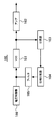
- the magnetic field resonance wireless power transmission system 10d includes a magnetic field resonance power transmission device 100d and a magnetic field resonance power reception device 200d.
- the magnetic field resonance power transmission apparatus 100 d includes a resonance coil 110, a coil 120, an AC power supply 130, and a detection unit 180 that detects the amount of power generated in the coil 120.
- the coupling variable unit 280 generates 1-bit demodulated data from the detection unit 180 by changing the distance d between the resonance coil 210 and the coil 220 to d0 and d1 based on the communication data. Is possible.
- the magnetic field resonance wireless power transmission system 10d can perform data communication without providing a new communication module or the like, the magnetic field resonance power transmission device 100d having a communication function, and the magnetic field resonance The cost of the power receiving device 200d can be reduced.
- a characteristic 2a represents a transmission power characteristic when the resonance frequency of the resonance coil 210 matches the target frequency f0. In the characteristic 2a, the transmission power takes a peak value when the frequency is f0. In the characteristic 2a, the vicinity of the peak value is distorted, which is considered to be affected by conditions other than the resonance frequency.
- the resonance frequency variable unit 270 changes the capacitance C of the resonance coil 210 to c0, c1, c2, c3 (c0 ⁇ c1 ⁇ c2 ⁇ c3) based on the communication data. Further, the detection unit 180 is supplied with reference power amounts Ref1, Ref2, Ref3.
- Step S108 The magnetic field resonance power transmitting apparatus starts power transmission to the magnetic field resonance power receiving apparatus. Note that step S108 may be performed before step S101. Step S108 may be performed in parallel with a series of processes from step S101 to step S107.
Abstract
Description
なお、例えば、体内埋め込み式微小刺激装置の内蔵型電源の充電レベルを、非接触通信により外部に送信する技術がある(例えば、特許文献1参照)。また、非接触通信に磁界と共鳴を用いる技術がある(例えば、特許文献2から4参照)。 For this reason, it is conceivable that a magnetic resonance wireless power transmission system also has a function of performing wireless communication.
For example, there is a technique for transmitting the charge level of the built-in power source of the implantable micro stimulator to the outside by non-contact communication (see, for example, Patent Document 1). Further, there is a technique that uses a magnetic field and resonance for non-contact communication (for example, see
この磁界共鳴送電装置は、共振コイルと、共振コイルに交流電流を発生させる交流電源と、交流電源が共振コイルに発生させる交流電流の周波数を通信データに基づいて変化させる周波数可変部と、を有する。 In order to achieve the above object, the following magnetic field resonance power transmission apparatus is provided.
The magnetic field resonance power transmission apparatus includes a resonance coil, an AC power source that generates an AC current in the resonance coil, and a frequency variable unit that changes the frequency of the AC current generated by the AC power source in the resonance coil based on communication data. .
本発明の上記及び他の目的、特徴及び利点は本発明の例として好ましい実施の形態を表す添付の図面と関連した以下の説明により明らかになるであろう。 According to the disclosed magnetic field resonance power transmission apparatus and magnetic field resonance power reception apparatus, it is possible to reduce the costs of the magnetic field resonance power transmission apparatus and the magnetic field resonance power reception apparatus having a communication function.
These and other objects, features and advantages of the present invention will become apparent from the following description taken in conjunction with the accompanying drawings which illustrate preferred embodiments by way of example of the present invention.
[第1の実施の形態]
図1は、第1の実施の形態に係る磁界共鳴ワイヤレス送電システムの一例を示した図である。 Hereinafter, embodiments will be described with reference to the drawings.
[First Embodiment]
FIG. 1 is a diagram illustrating an example of a magnetic resonance wireless power transmission system according to the first embodiment.
コイル120の材料には、例えば、銅(Cu)が用いられている。コイル120は、交流電源130から交流電流が供給されると、電磁誘導により共振コイル110に電力を供給して、共振コイル110に交流電流を発生させる。 The
For example, copper (Cu) is used as the material of the
周波数可変部140は、磁界共鳴送電装置100と磁界共鳴受電装置200とが通信を行う際、通信データに基づいて交流電源130が発生する交流電流の周波数を変調させる。このように交流電源130が発生する交流電流の周波数を変調させると、これに応じて共振コイル110が伝送する電力量も変調する。 Furthermore, the magnetic field resonance
When the magnetic field resonance
磁界共鳴受電装置200は、磁界共鳴送電装置100の共振コイル110から電力が伝送される共振コイル210と、共振コイル210に伝送された電力が供給されるコイル220とを有する。なお、電力伝送時における共振コイル110と共振コイル210との間の距離は、例えば、数10cmから2m程度を想定している。 Next, the magnetic field resonance
The magnetic field resonance
共振コイル110,210は、図2に示すように、インダクタンスLと、容量Cとを備えるLC共振回路を構成している。LC共振回路の共振周波数fは、次の式で表される。
f=ω/2π=1/{2π(LC)1/2}・・・(1)
図3は、第1の実施の形態に係る交流電源及び周波数可変部の具体例を示した図である。 FIG. 2 is an equivalent circuit diagram showing an example of the resonance coil according to the first embodiment.
As shown in FIG. 2, the
f = ω / 2π = 1 / {2π (LC) 1/2 } (1)
FIG. 3 is a diagram illustrating a specific example of the AC power supply and the frequency variable unit according to the first embodiment.
PLL回路160は、入力電圧に応じた発振周波数を備える交流電流を出力する電圧制御発振器(VCO:voltage controlled oscillator)161と、電圧制御発振器161から出力された交流電流を増幅してコイル120に出力するアンプ162と、電圧制御発振器161から出力された交流電流を分周する分周器163とを有する。 In this example, the
The
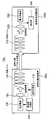
磁界共鳴受電装置200aは、共振コイル210と、コイル220と、整流回路250と、レギュレータ260と、バッテリコントローラ231と、バッテリ230aと、検出部240とを有する。 FIG. 4 is a diagram illustrating a specific example of the magnetic field resonance power receiving apparatus according to the first embodiment.
The magnetic field resonance
グラフの横軸は交流電源130が発生する交流電流の周波数を示し、縦軸は伝送電力(dB)を示す。ここで、伝送電力とは、共振コイル110から共振コイル210に伝送される電力である。 FIG. 5 is a graph illustrating an example of a power transmission state of the magnetic field resonance wireless power transmission system according to the first embodiment.
The horizontal axis of the graph indicates the frequency of the alternating current generated by the
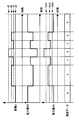
図6では、交流電源130が発生する交流電流の周波数、検出部240が検出する電力量、及び、検出部240が生成する復調データの変化の様子が示されている。 6 and 7 are timing charts illustrating an example of data transmission of the magnetic field resonance wireless power transmission system according to the first embodiment.
In FIG. 6, the frequency of the AC current generated by the
この例では、通信時、周波数可変部140が通信データに基づいて交流電源130が発生する交流電流の周波数を、f0,f1に変化させている。また、検出部240には、参照電力量Refが供給されている。 Here, the resonance frequency of the
In this example, during communication, the frequency
なお、ここでは、共振コイル110及び共振コイル210の共振周波数はf0である。また、周波数f0,f1,f2,f3は、図5の周波数f0,f1,f2,f3とそれぞれ対応しているものとする。 FIG. 7 shows changes in the frequency of the alternating current generated by the alternating
Here, the resonance frequency of the
[第2の実施の形態]
図8は、第2の実施の形態に係る磁界共鳴ワイヤレス送電システムの一例を示した図である。 Next, an embodiment in which a communication data modulation method is different from that of the first embodiment will be described as a second embodiment.
[Second Embodiment]
FIG. 8 is a diagram illustrating an example of a magnetic field resonance wireless power transmission system according to the second embodiment.
図9は、第2の実施の形態に係る電磁誘導による結合を変化させるための構成の一例を示した図である。 Thereby, similarly to the first embodiment, wireless communication of data is performed from the magnetic field resonance
FIG. 9 is a diagram illustrating an example of a configuration for changing coupling by electromagnetic induction according to the second embodiment.
次に、図10、及び、図11は、第2の実施の形態に係る磁界共鳴ワイヤレス送電システムのデータ伝送の一例を示すタイミングチャートである。 In addition, the coupling state by electromagnetic induction can be changed by changing the ratio of the number of turns of the coil wire between the
Next, FIG. 10 and FIG. 11 are timing charts showing an example of data transmission of the magnetic field resonance wireless power transmission system according to the second embodiment.
この例では、通信時、結合可変部170が通信データに基づいて、共振コイル110とコイル120との間の距離dを、d0,d1(d0<d1)に変化させている。また、検出部240には、参照電力量Refが供給されている。 FIG. 10 shows a change in the distance d between the
In this example, during communication, the
この例では、通信時、結合可変部170が通信データに基づいて、共振コイル110とコイル120との間の距離dを、d0,d1,d2,d3(d0<d1<d2<d3)に変化させている。また、検出部240には、参照電力量Ref1,Ref2,Ref3が供給されている。 FIG. 11 shows a change in the distance d between the
In this example, during communication, the
[第3の実施の形態]
図12は、第3の実施の形態に係る磁界共鳴ワイヤレス送電システムの一例を示した図である。 Next, an embodiment combining the communication data modulation method of the first embodiment and the communication data modulation method of the second embodiment will be described as a third embodiment.
[Third Embodiment]
FIG. 12 is a diagram illustrating an example of a magnetic field resonance wireless power transmission system according to the third embodiment.
図13では、交流電源130が発生する交流電流の周波数、共振コイル110とコイル120との間の距離d、検出部240が検出する電力量、及び、検出部240が生成する復調データの変化の様子が示されている。 FIG. 13 is a timing chart illustrating an example of data transmission in the magnetic field resonance wireless power transmission system according to the third embodiment.
In FIG. 13, the frequency of the alternating current generated by the alternating
図14は、第4の実施の形態に係る磁界共鳴ワイヤレス送電システムの一例を示した図である。 [Fourth Embodiment]
FIG. 14 is a diagram illustrating an example of a magnetic field resonance wireless power transmission system according to the fourth embodiment.
磁界共鳴送電装置100dは、共振コイル110と、コイル120と、交流電源130と、コイル120に発生する電力量を検出する検出部180とを有する。 The magnetic field resonance wireless
The magnetic field resonance
結合可変部280は、磁界共鳴送電装置100dと磁界共鳴受電装置200dとが通信を行う際、通信データに基づいて、共振コイル210とコイル220との電磁誘導による結合状態を変化させる。 The magnetic field resonance
When the magnetic resonance
共振コイル210とコイル220との電磁誘導による結合状態が変化すると、共振コイル210からコイル220に供給される電力量が変化する。これにより、共振コイル110から共振コイル210に伝送される電力量が変化する。 As a method for changing the coupling state of the
When the coupling state by electromagnetic induction between the
このタイミングチャートは、結合可変部280が、共振コイル210とコイル220との距離を変化させて、電磁誘導による結合を変化させている例に対応する。 Next, FIG.15 and FIG.16 is a timing chart which shows an example of the data transmission of the magnetic field resonance wireless power transmission system which concerns on 4th Embodiment.
This timing chart corresponds to an example in which the
[第5の実施の形態]
図17は、第5の実施の形態に係る磁界共鳴ワイヤレス送電システムの一例を示した図である。 Next, an embodiment in which a communication data modulation method is different from that of the fourth embodiment will be described as a fifth embodiment.
[Fifth Embodiment]
FIG. 17 is a diagram illustrating an example of a magnetic resonance wireless power transmission system according to the fifth embodiment.
即ち、共振周波数可変部270が、通信データに基づいて共振コイル210の共振周波数を変化させることで、共振コイル110から共振コイル210に伝送される電力量を変調させることが可能となる。 When the resonance frequency of the
That is, the resonance frequency
図18は、第5の実施の形態に係る磁界共鳴ワイヤレス送電システムの電力伝送状態の一例を示したグラフである。 As a result, as in the fourth embodiment, wireless communication of data is performed from the magnetic field resonance
FIG. 18 is a graph illustrating an example of a power transmission state of the magnetic resonance wireless power transmission system according to the fifth embodiment.
特性2aは、共振コイル210の共振周波数が目的とする周波数f0と一致している場合の伝送電力特性を示す。特性2aでは、伝送電力は、周波数がf0のときピーク値をとる。なお、特性2aでは、ピーク値の近傍が歪んでいるが、これは、共振周波数以外の条件が影響しているものと考えられる。 The horizontal axis of the graph indicates the frequency of the alternating current generated by the
A characteristic 2a represents a transmission power characteristic when the resonance frequency of the
次に、図19、及び、図20は、第5の実施の形態に係る磁界共鳴ワイヤレス送電システムのデータ伝送の一例を示すタイミングチャートである。 As described above, by changing the resonance frequency of the
Next, FIG. 19 and FIG. 20 are timing charts showing an example of data transmission of the magnetic field resonance wireless power transmission system according to the fifth embodiment.
図19では、共振コイル210の容量C、コイル220に供給される電力量W2、検出部180が検出する電力量W1、及び、検出部180が生成する復調データの変化の様子が示されている。 This timing chart corresponds to an example in which the resonance frequency
FIG. 19 shows changes in the capacitance C of the
[第6の実施の形態]
図21は、第6の実施の形態に係る磁界共鳴ワイヤレス送電システムの通信手順の一例を示したシーケンス図である。 Next, a communication procedure of the magnetic field resonance power transmission apparatus and the magnetic field resonance power reception apparatus in the magnetic field resonance wireless power transmission system will be described as a sixth embodiment.
[Sixth Embodiment]
FIG. 21 is a sequence diagram illustrating an example of a communication procedure of the magnetic field resonance wireless power transmission system according to the sixth embodiment.
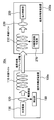
[ステップS102]磁界共鳴受電装置が、磁界共鳴送電装置が送信した信号を受信すると、通信用回路を起動する。ここで通信用回路とは、例えば、磁界共鳴受電装置に、第4の実施の形態の磁界共鳴受電装置10dを用いた場合は結合可変部280であり、第5の実施の形態の磁界共鳴受電装置10eを用いた場合は共振周波数可変部270である。 [Step S101] The magnetic field resonance power transmitting apparatus transmits a signal to the magnetic field resonance power receiving apparatus.
[Step S102] When the magnetic field resonance power receiving apparatus receives the signal transmitted by the magnetic field resonance power transmitting apparatus, the communication circuit is activated. Here, the communication circuit is, for example, the
[ステップS104]磁界共鳴送電装置が、磁界共鳴受電装置から送信された通信開始信号を受信すると、通信開始信号を磁界共鳴受電装置へ送信する。 [Step S103] The magnetic field resonance power receiving apparatus transmits a communication start signal to the magnetic field resonance power transmitting apparatus.
[Step S104] Upon receiving the communication start signal transmitted from the magnetic field resonance power receiving apparatus, the magnetic field resonance power transmitting apparatus transmits the communication start signal to the magnetic field resonance power receiving apparatus.
[ステップS106]磁界共鳴受電装置が、磁界共鳴送電装置との間の通信を開始する。 [Step S105] The magnetic field resonance power transmission apparatus starts communication with the magnetic field resonance power reception apparatus.
[Step S106] The magnetic field resonance power receiving apparatus starts communication with the magnetic field resonance power transmission apparatus.
なお、ステップS108をステップS101よりも前に実施することとしてもよい。また、ステップS108を、ステップS101からステップS107までの一連の処理と並行して実施することとしてもよい。 [Step S108] The magnetic field resonance power transmitting apparatus starts power transmission to the magnetic field resonance power receiving apparatus.
Note that step S108 may be performed before step S101. Step S108 may be performed in parallel with a series of processes from step S101 to step S107.
100 磁界共鳴送電装置
110,210 共振コイル
120,220 コイル
130 交流電源
140 周波数可変部
200 磁界共鳴受電装置
230 電力受給部
240 検出部 DESCRIPTION OF
Claims (10)
- 共振コイルと、
前記共振コイルに交流電流を発生させる交流電源と、
前記交流電源が前記共振コイルに発生させる交流電流の周波数を通信データに基づいて変化させる周波数可変部と、
を有することを特徴とする磁界共鳴送電装置。 A resonant coil;
An AC power source for generating an AC current in the resonance coil;
A frequency variable unit that changes the frequency of an alternating current generated by the alternating current power source in the resonance coil based on communication data;
A magnetic field resonance power transmission apparatus comprising: - 共振コイルと、
前記共振コイルに電磁誘導により交流電流を発生させるコイルと、
前記コイルに交流電流を発生させる交流電源と、
前記共振コイルと前記コイルとの電磁誘導による結合状態を通信データに基づいて変化させる結合可変部と、
を有することを特徴とする磁界共鳴送電装置。 A resonant coil;
A coil for generating an alternating current by electromagnetic induction in the resonant coil;
An AC power source for generating an AC current in the coil;
A coupling variable unit that changes a coupling state by electromagnetic induction between the resonance coil and the coil based on communication data;
A magnetic field resonance power transmission apparatus comprising: - 前記結合可変部は、前記共振コイルと前記コイルとの間の距離を変化させることで、前記結合状態を変化させることを特徴とする請求の範囲第2項記載の磁界共鳴送電装置。 3. The magnetic field resonance power transmission apparatus according to claim 2, wherein the coupling variable unit changes the coupling state by changing a distance between the resonance coil and the coil.
- 前記結合可変部は、前記共振コイルと前記コイルとの間に磁性体を配置させることで、前記結合状態を変化させることを特徴とする請求の範囲第2項記載の磁界共鳴送電装置。 3. The magnetic field resonance power transmission apparatus according to claim 2, wherein the coupling variable unit changes the coupling state by disposing a magnetic body between the resonance coil and the coil.
- 前記結合可変部は、前記共振コイル又は前記コイルの角度を変化させることで、前記結合状態を変化させることを特徴とする請求の範囲第2項記載の磁界共鳴送電装置。 3. The magnetic field resonance power transmission apparatus according to claim 2, wherein the coupling variable unit changes the coupling state by changing the resonance coil or an angle of the coil.
- 前記結合可変部は、前記共振コイル又は前記コイルの負荷抵抗を変化させることで、前記結合状態を変化させることを特徴とする請求の範囲第2項記載の磁界共鳴送電装置。 3. The magnetic field resonance power transmission apparatus according to claim 2, wherein the coupling variable unit changes the coupling state by changing the resonance coil or a load resistance of the coil.
- 共振コイルと、
前記共振コイルから電磁誘導により電力が供給されるコイルと、
前記コイルに供給された電力を受給する電力受給部と、
前記共振コイルと前記コイルとの電磁誘導による結合状態を通信データに基づいて変化させる結合可変部と、
を有することを特徴とする磁界共鳴受電装置。 A resonant coil;
A coil to which power is supplied from the resonance coil by electromagnetic induction;
An electric power receiving unit for receiving electric power supplied to the coil;
A coupling variable unit that changes a coupling state by electromagnetic induction between the resonance coil and the coil based on communication data;
A magnetic field resonance power receiving apparatus comprising: - 前記結合可変部は、前記共振コイルと前記コイルとの間の距離を変化させることで、前記結合状態を変化させることを特徴とする請求の範囲第7項記載の磁界共鳴受電装置。 The magnetic field resonance power receiving apparatus according to claim 7, wherein the coupling variable unit changes the coupling state by changing a distance between the resonance coil and the coil.
- 共振コイルと、
前記共振コイルから電磁誘導により電力が供給されるコイルと、
前記コイルに供給された電力を受給する電力受給部と、
前記共振コイルの共振周波数を通信データに基づいて変化させる共振周波数可変部と、
を有することを特徴とする磁界共鳴受電装置。 A resonant coil;
A coil to which power is supplied from the resonance coil by electromagnetic induction;
An electric power receiving unit for receiving electric power supplied to the coil;
A resonance frequency variable unit that changes a resonance frequency of the resonance coil based on communication data;
A magnetic field resonance power receiving apparatus comprising: - 前記共振周波数可変部は、前記共振コイルの容量を変化させることで、前記共振周波数を変化させることを特徴とする請求の範囲第9項記載の磁界共鳴受電装置。 The magnetic resonance power receiving apparatus according to claim 9, wherein the resonance frequency variable unit changes the resonance frequency by changing a capacitance of the resonance coil.
Priority Applications (6)
| Application Number | Priority Date | Filing Date | Title |
|---|---|---|---|
| EP09852275.8A EP2515415A4 (en) | 2009-12-16 | 2009-12-16 | Magnetic-resonant-coupling power transmission apparatus and magnetic-resonant-coupling power reception apparatus |
| KR1020127010188A KR101383383B1 (en) | 2009-12-16 | 2009-12-16 | Magnetic resonance power transmitter and magnetic resonance power receiver |
| CN200980162438.7A CN102668323B (en) | 2009-12-16 | 2009-12-16 | Magnetic resonance power transmission device and magnetic resonance current-collecting device |
| PCT/JP2009/070953 WO2011074082A1 (en) | 2009-12-16 | 2009-12-16 | Magnetic-resonant-coupling power transmission apparatus and magnetic-resonant-coupling power reception apparatus |
| JP2011545885A JP5505425B2 (en) | 2009-12-16 | 2009-12-16 | Magnetic field resonance power transmission device, magnetic field resonance power reception device, magnetic field resonance power transmission / reception system, and magnetic field resonance power transmission / reception method |
| US13/462,014 US9450455B2 (en) | 2009-12-16 | 2012-05-02 | Magnetic resonance power transmitter and magnetic resonance power receiver |
Applications Claiming Priority (1)
| Application Number | Priority Date | Filing Date | Title |
|---|---|---|---|
| PCT/JP2009/070953 WO2011074082A1 (en) | 2009-12-16 | 2009-12-16 | Magnetic-resonant-coupling power transmission apparatus and magnetic-resonant-coupling power reception apparatus |
Related Child Applications (1)
| Application Number | Title | Priority Date | Filing Date |
|---|---|---|---|
| US13/462,014 Continuation US9450455B2 (en) | 2009-12-16 | 2012-05-02 | Magnetic resonance power transmitter and magnetic resonance power receiver |
Publications (1)
| Publication Number | Publication Date |
|---|---|
| WO2011074082A1 true WO2011074082A1 (en) | 2011-06-23 |
Family
ID=44166877
Family Applications (1)
| Application Number | Title | Priority Date | Filing Date |
|---|---|---|---|
| PCT/JP2009/070953 WO2011074082A1 (en) | 2009-12-16 | 2009-12-16 | Magnetic-resonant-coupling power transmission apparatus and magnetic-resonant-coupling power reception apparatus |
Country Status (6)
| Country | Link |
|---|---|
| US (1) | US9450455B2 (en) |
| EP (1) | EP2515415A4 (en) |
| JP (1) | JP5505425B2 (en) |
| KR (1) | KR101383383B1 (en) |
| CN (1) | CN102668323B (en) |
| WO (1) | WO2011074082A1 (en) |
Cited By (15)
| Publication number | Priority date | Publication date | Assignee | Title |
|---|---|---|---|---|
| WO2013031988A1 (en) * | 2011-09-02 | 2013-03-07 | 富士通株式会社 | Power relay |
| JP2013062987A (en) * | 2011-09-14 | 2013-04-04 | Toshiba Corp | Wireless power transmission device and wireless power transmission method |
| JP2013074645A (en) * | 2011-09-26 | 2013-04-22 | Toshiba Corp | Wireless power transmission system, power transmission device, and power reception device |
| WO2013114576A1 (en) * | 2012-01-31 | 2013-08-08 | 富士通株式会社 | Power transmission device, power transmission system, and power transmission method |
| US20130264864A1 (en) * | 2012-04-10 | 2013-10-10 | Panasonic Corporation | Wireless power transmission system, power transmitting device, and power receiving device |
| WO2014073298A1 (en) * | 2012-11-06 | 2014-05-15 | 株式会社Ihi | Contactless electric power supply system |
| JP2014524732A (en) * | 2011-08-24 | 2014-09-22 | サムスン エレクトロニクス カンパニー リミテッド | Communication system using wireless power |
| JP2014204452A (en) * | 2013-04-01 | 2014-10-27 | 日東電工株式会社 | Power reception apparatus |
| US8933589B2 (en) | 2012-02-07 | 2015-01-13 | The Gillette Company | Wireless power transfer using separately tunable resonators |
| JPWO2013031988A1 (en) * | 2011-09-02 | 2015-03-23 | 富士通株式会社 | Power repeater |
| CN104584446A (en) * | 2012-08-31 | 2015-04-29 | 高通股份有限公司 | Systems and methods for decoupling a plurality of wireless charging transmitters |
| JP2017153362A (en) * | 2017-05-02 | 2017-08-31 | 京セラ株式会社 | Power transmission apparatus and wireless power transmission system |
| WO2018180529A1 (en) * | 2017-03-28 | 2018-10-04 | ソニーセミコンダクタソリューションズ株式会社 | Signal processing device and method |
| JP2018198535A (en) * | 2011-12-07 | 2018-12-13 | 株式会社半導体エネルギー研究所 | Non-contact power transmission device |
| JP2020025457A (en) * | 2011-12-16 | 2020-02-13 | 株式会社半導体エネルギー研究所 | Power reception device |
Families Citing this family (35)
| Publication number | Priority date | Publication date | Assignee | Title |
|---|---|---|---|---|
| US9412513B2 (en) * | 2012-03-30 | 2016-08-09 | Tdk Corporation | Wireless power transmission system |
| CN109067014B (en) | 2012-09-05 | 2022-04-15 | 瑞萨电子株式会社 | Non-contact charging device |
| EP2985874B1 (en) * | 2013-03-29 | 2017-06-14 | Nissan Motor Co., Ltd | Non-contact power supply system |
| CN104242477A (en) * | 2013-06-24 | 2014-12-24 | 海尔集团技术研发中心 | Wireless electric energy transmission system with impurity detection function and impurity detection method |
| KR102125917B1 (en) | 2013-08-07 | 2020-07-08 | 엘지이노텍 주식회사 | Wireless power transmitting device |
| CN103390925A (en) * | 2013-08-12 | 2013-11-13 | 苏州启智机电技术有限公司 | Resonant type electronic charger |
| WO2015046640A1 (en) * | 2013-09-25 | 2015-04-02 | Korea Electronics Technology Institute | Management protocol of wireless power transfer for multi-devices |
| WO2015046639A1 (en) * | 2013-09-25 | 2015-04-02 | Korea Electronics Technology Institute | In-band control protocole for wireless power transfer |
| JP5579952B1 (en) * | 2013-12-10 | 2014-08-27 | 中国電力株式会社 | Power transmission device, power supply system |
| JP6392550B2 (en) * | 2014-02-10 | 2018-09-19 | ローム株式会社 | Wireless power receiving apparatus and control circuit thereof, electronic device using the same, and abnormality detection method |
| US10084343B2 (en) | 2014-06-13 | 2018-09-25 | Empire Technology Development Llc | Frequency changing encoded resonant power transfer |
| US10069324B2 (en) | 2014-09-08 | 2018-09-04 | Empire Technology Development Llc | Systems and methods for coupling power to devices |
| US10320228B2 (en) | 2014-09-08 | 2019-06-11 | Empire Technology Development Llc | Power coupling device |
| DE102014118040B4 (en) * | 2014-12-05 | 2017-08-24 | Fraunhofer-Gesellschaft zur Förderung der angewandten Forschung e.V. | Control circuit for a base station for transmitting energy to a receiver by means of an electrical resonant circuit, evaluation device, method and computer program |
| KR20160142927A (en) * | 2015-06-03 | 2016-12-14 | 인천대학교 산학협력단 | Wireless Power Charging Apparatus and Method for Mobile |
| JP6647683B2 (en) * | 2015-06-25 | 2020-02-14 | 新東工業株式会社 | Apparatus and method for evaluating surface properties of steel |
| CN108141191B (en) * | 2015-08-24 | 2021-05-25 | 加利福尼亚大学董事会 | Low power magnetic field body area network |
| USD876628S1 (en) | 2016-07-20 | 2020-02-25 | Nyxoah S.A. | Medical implant |
| USD988519S1 (en) | 2016-09-12 | 2023-06-06 | Nyxoah S.A. | Patch |
| FR3060234B1 (en) | 2016-12-13 | 2019-05-10 | Continental Automotive France | METHOD OF CHARGING A MOBILE TERMINAL BY A MOBILE DEVICE FOR ONBOARDING ON A MOTOR VEHICLE AND RELATED CHARGING DEVICE |
| CA3054180A1 (en) | 2017-02-28 | 2018-09-07 | Nyxoah SA | Surgical implant system |
| NO20211061A1 (en) | 2019-04-05 | 2021-09-03 | Halliburton Energy Services Inc | Circular polarization correction in nuclear magnetic resonsance (NMR) logging |
| NO20211062A1 (en) * | 2019-04-05 | 2021-09-03 | Halliburton Energy Services Inc | Reverse circular polarization based antenna orientation |
| WO2021059285A1 (en) * | 2019-09-26 | 2021-04-01 | Soreq Nuclear Research Center | Wireless enhanced power transfer |
| US10892800B1 (en) | 2020-01-06 | 2021-01-12 | Nucurrent, Inc. | Systems and methods for wireless power transfer including pulse width encoded data communications |
| US11303164B2 (en) | 2020-07-24 | 2022-04-12 | Nucurrent, Inc. | Low cost communications demodulation for wireless power transmission system |
| US11303165B2 (en) | 2020-07-24 | 2022-04-12 | Nucurrent, Inc. | Low cost communications demodulation for wireless power receiver system |
| WO2022020581A1 (en) * | 2020-07-24 | 2022-01-27 | Nucurrent, Inc. | Low cost communications demodulation for wireless power transfer system |
| US11811244B2 (en) | 2021-02-01 | 2023-11-07 | Nucurrent, Inc. | Automatic gain control for communications demodulation in wireless power transmitters |
| US11277034B1 (en) | 2021-02-01 | 2022-03-15 | Nucurrent, Inc. | Systems and methods for receiver beaconing in wireless power systems |
| US11431205B2 (en) | 2021-02-01 | 2022-08-30 | Nucurrent, Inc. | Systems and methods for receiver beaconing in wireless power systems |
| US11569694B2 (en) | 2021-02-01 | 2023-01-31 | Nucurrent, Inc. | Automatic gain control for communications demodulation in wireless power receivers |
| US11431204B2 (en) | 2021-02-01 | 2022-08-30 | Nucurrent, Inc. | Automatic gain control for communications demodulation in wireless power transfer systems |
| US11277031B1 (en) | 2021-02-01 | 2022-03-15 | Nucurrent, Inc. | Automatic gain control for communications demodulation in wireless power transmitters |
| US11277035B1 (en) | 2021-02-01 | 2022-03-15 | Nucurrent, Inc. | Automatic gain control for communications demodulation in wireless power transmitters |
Citations (4)
| Publication number | Priority date | Publication date | Assignee | Title |
|---|---|---|---|---|
| JPH0654824A (en) | 1990-07-25 | 1994-03-01 | Magnetech Sa | Wireless receiver for camera by nuclear magnetic resonance |
| JP2005531371A (en) | 2002-06-28 | 2005-10-20 | アドヴァンスト バイオニックス コーポレイション | Micro stimulator with built-in power supply and interactive telemetry system |
| US20080174267A1 (en) * | 2007-01-17 | 2008-07-24 | Seiko Epson Corporation | Power transmission control device, power reception control device, non-contact power transmission system, power transmission device, power reception device and electronic instrument |
| JP2008535611A (en) | 2005-04-15 | 2008-09-04 | コーニンクレッカ フィリップス エレクトロニクス エヌ ヴィ | Antenna having a communication unit and picking up magnetic resonance signals |
Family Cites Families (30)
| Publication number | Priority date | Publication date | Assignee | Title |
|---|---|---|---|---|
| JPH0829143B2 (en) | 1986-04-30 | 1996-03-27 | 株式会社島津製作所 | High frequency excitation coil tuning measurement method for MRI apparatus |
| JPH0278347A (en) * | 1988-09-14 | 1990-03-19 | Nippon Signal Co Ltd:The | Transmitter between equipment on ground and on vehicle |
| JP2879285B2 (en) * | 1993-02-19 | 1999-04-05 | 富士通電装株式会社 | Communication control method for electric vehicles |
| JPH0829143A (en) | 1994-07-13 | 1996-02-02 | Mazda Motor Corp | Method and apparatus for inspecting surface state |
| US5760584A (en) | 1996-08-16 | 1998-06-02 | General Electric Company | Shield for MR system RF coil provided with multiple capacitive channels for RF current flow |
| CN1105414C (en) * | 1997-02-03 | 2003-04-09 | 索尼公司 | Equipment and method for transmitting electric power |
| JP3629176B2 (en) * | 2000-02-09 | 2005-03-16 | 株式会社東芝 | Portable wireless terminal |
| ATE346279T1 (en) * | 2001-06-27 | 2006-12-15 | Fraunhofer Ges Forschung | METHOD AND DEVICE FOR PREPARING A SENSOR SIGNAL OF A POSITION SENSOR FOR TRANSMISSION TO AN EVALUATION UNIT |
| US7428438B2 (en) | 2002-06-28 | 2008-09-23 | Boston Scientific Neuromodulation Corporation | Systems and methods for providing power to a battery in an implantable stimulator |
| US8386048B2 (en) | 2002-06-28 | 2013-02-26 | Boston Scientific Neuromodulation Corporation | Systems and methods for communicating with or providing power to an implantable stimulator |
| US7822480B2 (en) | 2002-06-28 | 2010-10-26 | Boston Scientific Neuromodulation Corporation | Systems and methods for communicating with an implantable stimulator |
| JP4217106B2 (en) | 2003-05-23 | 2009-01-28 | パナソニック株式会社 | Monolithic microwave integrated circuit |
| KR20040072581A (en) | 2004-07-29 | 2004-08-18 | (주)제이씨 프로텍 | An amplification relay device of electromagnetic wave and a radio electric power conversion apparatus using the above device |
| US7825543B2 (en) | 2005-07-12 | 2010-11-02 | Massachusetts Institute Of Technology | Wireless energy transfer |
| US7741734B2 (en) | 2005-07-12 | 2010-06-22 | Massachusetts Institute Of Technology | Wireless non-radiative energy transfer |
| JP4413236B2 (en) * | 2007-02-16 | 2010-02-10 | セイコーエプソン株式会社 | Power reception control device, power transmission control device, non-contact power transmission system, power reception device, power transmission device, and electronic device |
| JP4649430B2 (en) | 2007-03-20 | 2011-03-09 | セイコーエプソン株式会社 | Non-contact power transmission device |
| CN101330229A (en) * | 2007-06-21 | 2008-12-24 | 北京市北邮信息科技发展有限责任公司 | Non-contact type apparatus for transmitting electric energy |
| CN101849342B (en) * | 2007-09-17 | 2014-10-29 | 高通股份有限公司 | High efficiency and power transfer in wireless power magnetic resonators |
| JP4453741B2 (en) * | 2007-10-25 | 2010-04-21 | トヨタ自動車株式会社 | Electric vehicle and vehicle power supply device |
| JP4974171B2 (en) | 2007-12-07 | 2012-07-11 | ソニーモバイルコミュニケーションズ株式会社 | Non-contact wireless communication device, method for adjusting resonance frequency of non-contact wireless communication antenna, and portable terminal device |
| US8855554B2 (en) * | 2008-03-05 | 2014-10-07 | Qualcomm Incorporated | Packaging and details of a wireless power device |
| JP4572949B2 (en) * | 2008-04-08 | 2010-11-04 | ソニー株式会社 | Wireless communication apparatus, wireless communication system, wireless communication method, and program |
| JP2009253762A (en) * | 2008-04-08 | 2009-10-29 | Sony Corp | Radio communication device, wireless communication system, radio communication method and program |
| JP4911148B2 (en) * | 2008-09-02 | 2012-04-04 | ソニー株式会社 | Contactless power supply |
| JP5238420B2 (en) * | 2008-09-11 | 2013-07-17 | 矢崎総業株式会社 | Wireless charging system for vehicles |
| JP2010068634A (en) * | 2008-09-11 | 2010-03-25 | Yazaki Corp | Wireless charging system for vehicle |
| JP5308127B2 (en) * | 2008-11-17 | 2013-10-09 | 株式会社豊田中央研究所 | Power supply system |
| JP5324901B2 (en) * | 2008-12-09 | 2013-10-23 | 日立コンシューマエレクトロニクス株式会社 | Non-contact power transmission system |
| JP5533856B2 (en) | 2009-03-30 | 2014-06-25 | 富士通株式会社 | Wireless power supply system, wireless power transmitting apparatus, and wireless power receiving apparatus |
-
2009
- 2009-12-16 EP EP09852275.8A patent/EP2515415A4/en not_active Withdrawn
- 2009-12-16 JP JP2011545885A patent/JP5505425B2/en not_active Expired - Fee Related
- 2009-12-16 CN CN200980162438.7A patent/CN102668323B/en not_active Expired - Fee Related
- 2009-12-16 KR KR1020127010188A patent/KR101383383B1/en not_active IP Right Cessation
- 2009-12-16 WO PCT/JP2009/070953 patent/WO2011074082A1/en active Application Filing
-
2012
- 2012-05-02 US US13/462,014 patent/US9450455B2/en not_active Expired - Fee Related
Patent Citations (4)
| Publication number | Priority date | Publication date | Assignee | Title |
|---|---|---|---|---|
| JPH0654824A (en) | 1990-07-25 | 1994-03-01 | Magnetech Sa | Wireless receiver for camera by nuclear magnetic resonance |
| JP2005531371A (en) | 2002-06-28 | 2005-10-20 | アドヴァンスト バイオニックス コーポレイション | Micro stimulator with built-in power supply and interactive telemetry system |
| JP2008535611A (en) | 2005-04-15 | 2008-09-04 | コーニンクレッカ フィリップス エレクトロニクス エヌ ヴィ | Antenna having a communication unit and picking up magnetic resonance signals |
| US20080174267A1 (en) * | 2007-01-17 | 2008-07-24 | Seiko Epson Corporation | Power transmission control device, power reception control device, non-contact power transmission system, power transmission device, power reception device and electronic instrument |
Non-Patent Citations (4)
| Title |
|---|
| "PROCEEDINGS OF THE 2008 IEICE GENERAL CONFERENCE, 2008.03.05", vol. B-1-14, article QIAOWEI YUAN ET AL.: "Wireless Power Transfer Efficiency between Helical Coils", pages: 14, XP009852275 * |
| ANDRE KURS ET AL.: "Wireless Power Transfer via Strongly Coupled Magnetic Resonances", SCIENCE, vol. 317, 6 July 2007 (2007-07-06), pages 83 - 86, XP008154870 * |
| MARIN SOLJACIC ET AL.: "Denryoku o Musen Denso suru Gijutsu o Kaihatsu, Jikken de 60W no Denkyu o Tento", NIKKEI ELECTRONICS, vol. 966, 3 December 2007 (2007-12-03), pages 117 - 128, XP008154918 * |
| See also references of EP2515415A4 |
Cited By (33)
| Publication number | Priority date | Publication date | Assignee | Title |
|---|---|---|---|---|
| US10312740B2 (en) | 2011-08-24 | 2019-06-04 | Samsung Electronics Co., Ltd. | Communication system using wireless power |
| US9627914B2 (en) | 2011-08-24 | 2017-04-18 | Samsung Electronics Co., Ltd. | Communication system using wireless power |
| JP2014524732A (en) * | 2011-08-24 | 2014-09-22 | サムスン エレクトロニクス カンパニー リミテッド | Communication system using wireless power |
| JPWO2013031988A1 (en) * | 2011-09-02 | 2015-03-23 | 富士通株式会社 | Power repeater |
| US9558884B2 (en) | 2011-09-02 | 2017-01-31 | Fujitsu Limited | Power transmission apparatus |
| WO2013031025A1 (en) * | 2011-09-02 | 2013-03-07 | 富士通株式会社 | Power relay |
| WO2013031988A1 (en) * | 2011-09-02 | 2013-03-07 | 富士通株式会社 | Power relay |
| JP2013062987A (en) * | 2011-09-14 | 2013-04-04 | Toshiba Corp | Wireless power transmission device and wireless power transmission method |
| JP2013074645A (en) * | 2011-09-26 | 2013-04-22 | Toshiba Corp | Wireless power transmission system, power transmission device, and power reception device |
| JP2018198535A (en) * | 2011-12-07 | 2018-12-13 | 株式会社半導体エネルギー研究所 | Non-contact power transmission device |
| JP2019205350A (en) * | 2011-12-07 | 2019-11-28 | 株式会社半導体エネルギー研究所 | Non-contact power transmission device |
| JP2020025457A (en) * | 2011-12-16 | 2020-02-13 | 株式会社半導体エネルギー研究所 | Power reception device |
| US9672979B2 (en) | 2012-01-31 | 2017-06-06 | Fujitsu Limited | Power transmitting apparatus, power transmission system, and power transmission method |
| JPWO2013114576A1 (en) * | 2012-01-31 | 2015-05-11 | 富士通株式会社 | Power transmission device, power transmission system, and power transmission method |
| WO2013114576A1 (en) * | 2012-01-31 | 2013-08-08 | 富士通株式会社 | Power transmission device, power transmission system, and power transmission method |
| US8933589B2 (en) | 2012-02-07 | 2015-01-13 | The Gillette Company | Wireless power transfer using separately tunable resonators |
| US9634495B2 (en) | 2012-02-07 | 2017-04-25 | Duracell U.S. Operations, Inc. | Wireless power transfer using separately tunable resonators |
| WO2013153736A1 (en) * | 2012-04-10 | 2013-10-17 | パナソニック株式会社 | Wireless power transmitting apparatus, power transmitting apparatus, and power receiving apparatus |
| US20160225519A1 (en) * | 2012-04-10 | 2016-08-04 | Panasonic Intellectual Property Management Co., Ltd. | Wireless power transmission system, power transmitting device, and power receiving device |
| US9349530B2 (en) | 2012-04-10 | 2016-05-24 | Panasonic Intellectual Property Management Co., Ltd. | Wireless power transmission system, power transmitting device, and power receiving device |
| JPWO2013153736A1 (en) * | 2012-04-10 | 2015-12-17 | パナソニックIpマネジメント株式会社 | Wireless power transmission device, power transmission device, and power reception device |
| US10008323B2 (en) | 2012-04-10 | 2018-06-26 | Panasonic Intellectual Property Management Co., Ltd. | Wireless power transmission system, power transmitting device, and power receiving device |
| US20130264864A1 (en) * | 2012-04-10 | 2013-10-10 | Panasonic Corporation | Wireless power transmission system, power transmitting device, and power receiving device |
| TWI553994B (en) * | 2012-08-31 | 2016-10-11 | 高通公司 | Systems and methods for decoupling multiple wireless charging transmitters |
| CN104584446A (en) * | 2012-08-31 | 2015-04-29 | 高通股份有限公司 | Systems and methods for decoupling a plurality of wireless charging transmitters |
| JP2014093916A (en) * | 2012-11-06 | 2014-05-19 | Ihi Corp | Contactless power supply device |
| US9912169B2 (en) | 2012-11-06 | 2018-03-06 | Ihi Corporation | Wireless power supply system |
| WO2014073298A1 (en) * | 2012-11-06 | 2014-05-15 | 株式会社Ihi | Contactless electric power supply system |
| JP2014204452A (en) * | 2013-04-01 | 2014-10-27 | 日東電工株式会社 | Power reception apparatus |
| WO2018180529A1 (en) * | 2017-03-28 | 2018-10-04 | ソニーセミコンダクタソリューションズ株式会社 | Signal processing device and method |
| JPWO2018180529A1 (en) * | 2017-03-28 | 2020-04-09 | ソニーセミコンダクタソリューションズ株式会社 | Signal processing apparatus and method |
| JP7187439B2 (en) | 2017-03-28 | 2022-12-12 | ソニーセミコンダクタソリューションズ株式会社 | Signal processing apparatus and method |
| JP2017153362A (en) * | 2017-05-02 | 2017-08-31 | 京セラ株式会社 | Power transmission apparatus and wireless power transmission system |
Also Published As
| Publication number | Publication date |
|---|---|
| EP2515415A4 (en) | 2016-11-09 |
| CN102668323B (en) | 2016-08-03 |
| JP5505425B2 (en) | 2014-05-28 |
| CN102668323A (en) | 2012-09-12 |
| US9450455B2 (en) | 2016-09-20 |
| KR101383383B1 (en) | 2014-04-08 |
| KR20120073284A (en) | 2012-07-04 |
| EP2515415A1 (en) | 2012-10-24 |
| JPWO2011074082A1 (en) | 2013-04-25 |
| US20120212074A1 (en) | 2012-08-23 |
Similar Documents
| Publication | Publication Date | Title |
|---|---|---|
| JP5505425B2 (en) | Magnetic field resonance power transmission device, magnetic field resonance power reception device, magnetic field resonance power transmission / reception system, and magnetic field resonance power transmission / reception method | |
| JP5728612B2 (en) | Adaptive impedance tuning in wireless power transfer | |
| KR101184503B1 (en) | Wireless power transmission apparatus and transmission method thereof | |
| US9979316B2 (en) | Impedance compensation based on ratio of bus voltage and amplifier fundamental AC output voltage | |
| US9264108B2 (en) | Wireless power carrier-synchronous communication | |
| US9923405B2 (en) | Method and apparatus for wireless power in-band signaling by load generation | |
| US9979234B2 (en) | Resonant contactless power supply equipment, electrical transmitter and contactless power supply method | |
| CN103424133A (en) | System and method for measuring variable impedance elements in a wireless sensor | |
| CN106537801B (en) | Communication device, circuit, driving device, power supply device, tuning and discovery method | |
| US9773609B2 (en) | Power supply apparatus and power control method thereof | |
| WO2012090700A1 (en) | Wireless power feeder, wireless power receiver, and wireless transmission system | |
| US9711972B2 (en) | Auxiliary receiver coil to adjust receiver voltage and reactance | |
| US8368471B2 (en) | Resonance power generator | |
| KR102125917B1 (en) | Wireless power transmitting device | |
| US10439440B2 (en) | Charger and method of inductively charging a mobile device inside a motor vehicle | |
| US20170085113A1 (en) | Constant current radio frequency generator for a wireless charging system | |
| CN106505749B (en) | Method for stabilizing resonant frequency of resonant wireless power transmission coil by fractional order capacitor | |
| JP2012034524A (en) | Wireless power transmission apparatus | |
| US10720798B2 (en) | Coil configuration in a wireless power transmitter | |
| JP2016039647A (en) | Non-contact power transmission device | |
| KR20150112160A (en) | Wireless Power Transfer System including Wireless Power Transfer System-Charger | |
| WO2017017828A1 (en) | Power transmission device, power reception device, and magnetic field resonance power transmission system equipped with same |
Legal Events
| Date | Code | Title | Description |
|---|---|---|---|
| WWE | Wipo information: entry into national phase |
Ref document number: 200980162438.7 Country of ref document: CN |
|
| 121 | Ep: the epo has been informed by wipo that ep was designated in this application |
Ref document number: 09852275 Country of ref document: EP Kind code of ref document: A1 |
|
| WWE | Wipo information: entry into national phase |
Ref document number: 2011545885 Country of ref document: JP |
|
| ENP | Entry into the national phase |
Ref document number: 20127010188 Country of ref document: KR Kind code of ref document: A |
|
| WWE | Wipo information: entry into national phase |
Ref document number: 2009852275 Country of ref document: EP |
|
| NENP | Non-entry into the national phase |
Ref country code: DE |