WO2011068000A1 - Hand-held wireless endoscope - Google Patents
Hand-held wireless endoscope Download PDFInfo
- Publication number
- WO2011068000A1 WO2011068000A1 PCT/JP2010/069032 JP2010069032W WO2011068000A1 WO 2011068000 A1 WO2011068000 A1 WO 2011068000A1 JP 2010069032 W JP2010069032 W JP 2010069032W WO 2011068000 A1 WO2011068000 A1 WO 2011068000A1
- Authority
- WO
- WIPO (PCT)
- Prior art keywords
- endoscope
- antenna
- battery
- disposed
- unit
- Prior art date
Links
Images


Classifications
-
- G—PHYSICS
- G02—OPTICS
- G02B—OPTICAL ELEMENTS, SYSTEMS OR APPARATUS
- G02B23/00—Telescopes, e.g. binoculars; Periscopes; Instruments for viewing the inside of hollow bodies; Viewfinders; Optical aiming or sighting devices
- G02B23/24—Instruments or systems for viewing the inside of hollow bodies, e.g. fibrescopes
- G02B23/2476—Non-optical details, e.g. housings, mountings, supports
- G02B23/2484—Arrangements in relation to a camera or imaging device
-
- A—HUMAN NECESSITIES
- A61—MEDICAL OR VETERINARY SCIENCE; HYGIENE
- A61B—DIAGNOSIS; SURGERY; IDENTIFICATION
- A61B1/00—Instruments for performing medical examinations of the interior of cavities or tubes of the body by visual or photographical inspection, e.g. endoscopes; Illuminating arrangements therefor
- A61B1/00002—Operational features of endoscopes
- A61B1/00011—Operational features of endoscopes characterised by signal transmission
- A61B1/00016—Operational features of endoscopes characterised by signal transmission using wireless means
-
- A—HUMAN NECESSITIES
- A61—MEDICAL OR VETERINARY SCIENCE; HYGIENE
- A61B—DIAGNOSIS; SURGERY; IDENTIFICATION
- A61B1/00—Instruments for performing medical examinations of the interior of cavities or tubes of the body by visual or photographical inspection, e.g. endoscopes; Illuminating arrangements therefor
- A61B1/227—Instruments for performing medical examinations of the interior of cavities or tubes of the body by visual or photographical inspection, e.g. endoscopes; Illuminating arrangements therefor for ears, i.e. otoscopes
-
- A—HUMAN NECESSITIES
- A61—MEDICAL OR VETERINARY SCIENCE; HYGIENE
- A61B—DIAGNOSIS; SURGERY; IDENTIFICATION
- A61B1/00—Instruments for performing medical examinations of the interior of cavities or tubes of the body by visual or photographical inspection, e.g. endoscopes; Illuminating arrangements therefor
- A61B1/233—Instruments for performing medical examinations of the interior of cavities or tubes of the body by visual or photographical inspection, e.g. endoscopes; Illuminating arrangements therefor for the nose, i.e. nasoscopes, e.g. testing of patency of Eustachian tubes
Definitions
- the present invention relates to an endoscope capable of hand-held wireless communication, in which an operator (operator) performs an operation by grasping a grasping portion of an endoscope main body.
- the endoscope body is laid horizontally, the insertion portion is extended substantially horizontally without greatly bending the insertion portion, and the distal end portion of the insertion portion faces the front of the patient's face. May be used by inserting into the nasal cavity.
- the operation unit itself as in Patent Literature 1 and Patent Literature 2 is used as a gun type (pistol) shape for an otolaryngological case. It is conceivable that the endoscope can be operated easily by extending the insertion portion in a substantially horizontal direction with respect to the front of the patient's face using the endoscope.
- the endoscope image acquired by the imaging device is wirelessly transmitted to the processing device, thereby eliminating the cable and improving the operability during the treatment.
- wireless endoscope As for an otolaryngological endoscope, since a cable is not necessary, even in a narrow examination room, there is no obstacle during the operation, and the wireless endoscope is very effective.
- the antenna for wirelessly communicating the endoscopic image converted into the radio signal with the processor is separated as much as possible from the human body, metal parts, electronic parts, etc. that obstruct radio waves.
- At least a part of the endoscope body is made of metal parts.
- the antenna directivity May affect the wireless communication performance and may not be able to obtain uniform directivity in the surrounding area. For this reason, an arrangement
- Patent Document 1 has no idea of applying a gun-type endoscope to a wireless endoscope.
- Patent Document 2 describes the arrangement of the gripper and the communication antenna, but does not consider the arrangement of communication antennas and electronic components that are supposed to improve the wireless communication performance with the outside.
- Patent Document 3 describes an example in which a high-frequency antenna for communication is mounted on a gun-type endoscope, the arrangement of the communication antenna takes into account the improvement of wireless communication performance with the outside. I can't say.
- the present invention not only improves gripping and operability, but also the human body of the operator holding the endoscope main body and the metal body inside the endoscope main body including the electric circuit are used for the antenna in wireless communication.
- An object of the present invention is to provide an endoscope in which influence on directivity is reduced and wireless communication performance is improved.
- An endoscope according to the present invention is inserted in a body cavity and has an observation optical system that images the inside of the body cavity and extends in the front-rear direction, and is provided on the rear end side of the insertion section and is gripped by an operator
- An endoscope main body having a grip portion for the first position, a first antenna disposed closer to the insertion portion than the grip portion, and a second disposed farther from the insertion portion than the grip portion.
- the first and second antennas are covered with a radio wave transmissive material in a state in which the metal material is separated from the radio wave directivity direction, and the observation optical system An image obtained by imaging the inside of the body cavity is converted into a radio signal, and the radio signal can be transmitted / received to / from the outside by the first and / or second antenna.
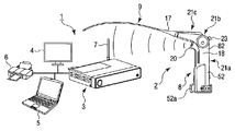
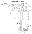
- FIG. 1 is a schematic diagram showing an overall configuration of an endoscope system according to an embodiment of the present invention.
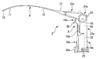
- FIG. 2 is a schematic left side view showing an appearance of an endoscope in the endoscope system according to the embodiment.
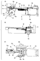
- FIG. 3 is a schematic diagram illustrating an internal configuration of an endoscope in the endoscope system according to the embodiment.
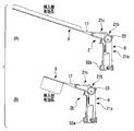
- FIG. 4A and FIG. 4B are schematic views showing the appearance of an endoscope when the effective length of the insertion portion is different in the endoscope system according to the embodiment.
- FIG. 5 is a schematic diagram illustrating an appearance of an endoscope in which an attachment is attached to the insertion portion of the endoscope system according to the embodiment.
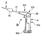
- FIG. 6 is a schematic diagram illustrating an appearance of an endoscope of the endoscope system according to the embodiment.
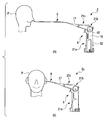
- FIG. 7 is a schematic diagram illustrating a state in which the operator holds the endoscope of the endoscope system according to the embodiment.
- FIG. 8A is a schematic view showing a state in which the distal end portion of the insertion portion of the endoscope of the endoscope system according to the embodiment is inserted into the nostril of the patient, and FIG. It is the schematic which shows the state which inserted the front-end
- FIG. 9A is a schematic view showing a state in which an exterior cover is attached to the bending operation portion of the bending portion of the endoscope of the endoscope system according to the embodiment, and FIG. It is the schematic which shows the bending operation part of the state removed, and FIG.9 (C) is a schematic perspective view which shows the state which looked at the flame
- FIG. 10 is a schematic view showing a conventional endoscope system and showing a fixed state of an exterior cover of the endoscope.
- FIG. 11 is a perspective view of a cylindrical body at the base of the endoscope body of the endoscope of the endoscope system according to the embodiment, and FIG. 11A is a second operation arranged on the front side.
- FIG. 10 is a schematic view showing a conventional endoscope system and showing a fixed state of an exterior cover of the endoscope.
- FIG. 11 is a perspective view of a cylindrical body at the base of the endoscope body of the
- FIG. 11 is a schematic diagram showing a switch (function changeover switch), and FIG. 11B is a schematic diagram showing a third operation switch (power switch) arranged on the rear side.
- FIG. 12 is a schematic diagram illustrating a first operation switch provided at a boundary portion on the front side of the base portion, the bent portion, and the head portion of the endoscope main body of the endoscope of the endoscope system according to the embodiment. It is a perspective view. 13 shows a state in which the first operation switch shown in FIG. 12 is attached, FIG. 13 (A) is a schematic view showing a state in which the exterior is removed, and FIG. 13 (B) is a view in FIG. 13 (A). It is the schematic which expands and shows the 1st operation switch enclosed with the broken line.
- FIG. 14A is a schematic view showing a substrate unit disposed at the base of the endoscope main body of the endoscope of the endoscope system according to the embodiment, and FIG. 14B is removed from the base.
- FIG. 14C is a schematic view showing a state in which the exterior of the boundary portion on the front side of the base portion, the bent portion, and the head portion of the endoscope body is removed.
- FIG. 15 is a schematic diagram illustrating a peripheral portion of an internal frame disposed at a base portion of an endoscope main body of an endoscope of an endoscope system according to an embodiment.
- FIG. 16 is a schematic diagram illustrating a state in which the light source unit is disposed in the bending operation unit of the endoscope main body of the endoscope of the endoscope system according to the embodiment.
- FIG. 17A is a schematic diagram showing an arrangement of electrical systems such as a substrate unit, a battery, an antenna, and a light source unit with respect to the endoscope of the endoscope system according to the embodiment
- FIG. 17 is a schematic diagram showing a direction in which the first antenna is arranged at a portion indicated by reference numeral 40a in FIG. 17A and a directing direction thereof
- FIG. 17C is a diagram showing the second antenna in FIG.
- FIG. 18 is a schematic diagram illustrating a bracket disposed on a board unit disposed inside an endoscope body of an endoscope of an endoscope system according to an embodiment.
- FIG. 19A is a schematic perspective view illustrating a state in which the cylindrical body is attached in a state where the substrate unit is disposed on the endoscope main body of the endoscope of the endoscope system according to the embodiment.
- 19 (B) is a schematic diagram of FIG. 19 (A), and FIG. 19 (C) shows that the rigid board shown in FIG. 19 (B) is tilted so that the cylindrical body can be mounted on the board unit.
- FIG. 20 is a front view illustrating a display device that displays an endoscopic image of the endoscope system according to the embodiment.
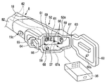
- FIG. 21 is a schematic perspective view showing a state in which a battery can be attached to and detached from a battery storage portion formed in a base portion of an endoscope main body of an endoscope of an endoscope system according to an embodiment. is there.
- FIG. 22 (A) is a schematic view showing a battery arranged in the battery storage part of the endoscope of the endoscope system according to the embodiment, and FIG. 22 (B) is a battery shown in FIG. 22 (A). It is the schematic which shows the state which observed from the opposite side, and shows the state which a battery expand
- FIG. 22 (A) is a schematic perspective view showing a state in which a battery can be attached to and detached from a battery storage portion formed in a base portion of an endoscope main body of an endoscope of an endoscope system according to an embodiment. is
- FIG. 23 is a schematic diagram illustrating a state in which the writing device is connected to the setting signal writing instrument arranged in the battery storage unit of the endoscope of the endoscope system according to the embodiment.
- FIG. 24A is a schematic diagram illustrating a state in which the setting signal writing instrument is stored in the battery storage portion of the endoscope of the endoscope system according to the embodiment, and FIG. It is a schematic sectional drawing which shows the attachment state of a fitting tool.
- FIG. 25A is a schematic perspective view showing a setting signal writing instrument disposed in the battery storage part of the endoscope of the endoscope system according to the embodiment, and FIG. It is a schematic perspective view which shows the battery arrange
- FIG. 26 is a schematic diagram illustrating a processing device of the endoscope system according to one embodiment.
- FIG. 27 is a schematic diagram illustrating a state in which an antenna is attached to the processing apparatus of the endoscope system according to the embodiment.
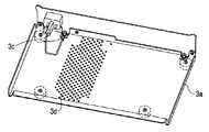
- FIG. 28 is a schematic perspective view showing the back surface of the housing of the processing apparatus of the endoscope system according to the embodiment.
- the wireless communication circuit 39 includes an electronic substrate having electronic components such as a wireless communication circuit 39, an image processing circuit 38, and antennas 40a and 40b for wireless communication, which will be described later.
- An endoscope system (hereinafter referred to as a wireless endoscope) that converts an endoscope image into a wireless signal, transmits the signal to the external processing device 3 or the like wirelessly, and displays the endoscope image on the external video display device 4 or the like.
- System 1 will be described as an example.
- an endoscope system 1 includes an endoscope 2, a processing device 3 that receives a radio signal transmitted from the endoscope 2, and converts the radio signal into a video signal.
- the display device 4 displays the video signal generated by the processing device 3 as a video.
- the processing device 3 and the display device 4 may be connected via a cord or the like, or the processing device 3 and the display device 4 may be capable of wireless communication.
- the endoscope 2 has an image processing circuit 38 (described later) that converts a captured video (endoscopic image) into a radio signal.
- a radio signal is transmitted from the transmission antennas 40a and 40b through a radio circuit 39 (described later) built in the endoscope 2 and connected to the image processing circuit 38, the radio signal is received by the reception antenna 7 connected to the processing device 3. Is received.
- the processing device 3 converts the radio signal into a video signal, and further performs image processing on the video signal.
- the video signal output from the processing device 3 is displayed as a video on the screen of the display device 4.
- the endoscope system 1 may include a computer 5 and a printing device 6.
- the computer 5 and the printing device 6 are connected to the processing device 3.
- the computer 5 appropriately sets circuits (electronic boards) 37, 38, and 39 and first to third operation switches 19a, 19b, and 19c on the board unit 30 of the endoscope 2 as described later, It has a function of accumulating and analyzing video signals generated by the processing device 3.
- the printing device 6 has a function of printing a still image extracted from the video signal generated by the processing device 3 and a document created by the computer 5.
- the endoscope 2 includes an endoscope operation unit (endoscope main body) 8 that is held and operated by a user, and front and back from the endoscope operation unit 8. And an insertion portion 9 that extends in the direction (long axis direction) and is inserted into the body cavity from the front side (front end side) toward the rear side (base end side).
- the upper end portion of the endoscope operation portion 8 that is long in the vertical direction is connected to the rear end portion (base end portion) of the insertion portion 9 that extends in the front-rear direction.
- the insertion portion 9 includes, in order from the front side to the rear side, a distal end rigid portion 10, a bending portion 11 that performs bending operation, and a long and flexible flexible tube portion 12.
- the bending portion 11 is connected to the rear end portion of the distal end rigid portion 10
- the flexible tube portion 12 is connected to the rear end portion of the bending portion 11.
- the rear end portion (rear end portion of the insertion portion 9) of the flexible tube portion 12 is connected to the distal end portion of a head portion 21c (to be described later) of the endoscope operation portion 8 via an oleome 17.
- the length of the insertion portion 9 of the endoscope 2 according to this embodiment can be set as appropriate.
- the endoscope 2 is used particularly for otolaryngology
- the insertion portion 9 of the endoscope 2 is inserted into the affected area
- the insertion portion 9 follows well even a sudden patient movement.
- the handling and procedure of the insertion part 9 become complicated. Therefore, the insertion portion 9 of the endoscope 2 according to this embodiment is not only flexible by adjusting the flexibility of the flexible tube portion 12, but as shown in FIG.
- the distal end hard portion 10 of the insertion portion 9 is flexible enough to be disposed at a position far from the mirror operation portion 8. Moreover, if the effective length of the insertion part 9 is shortened, an operator's camera shake can be suppressed. Therefore, according to the endoscope 2 according to this embodiment, the otolaryngology department can hold the endoscope 2 while maintaining an unreasonable posture by holding the endoscope 2 as shown in FIG. Can be examined.
- the insertion portion 9 extends in the front-rear direction, and the endoscope operation portion (endoscope main body) 8 is provided at the rear end thereof, so that the endoscope 2 can be used for treatments such as otolaryngology. Gripping and operability can be improved.
- the endoscope 2 is an endoscope that is particularly suitable for otolaryngology
- such an otolaryngology endoscope 2 inserts the insertion portion 9 nasally, for example.
- the flexible tube portion 12 of the insertion portion 9 shown in FIG. 4 (A) is soft, and its effective length is often about 300 mm so that it is suitable for observation of the hypopharynx and larynx.
- the effective length of the insertion portion 9 of the endoscope 2b when the insertion portion 9 is a short type is that the nasal cavity length of an adult male is usually about 60 mm.
- the insertion portion 9 of the otolaryngology flexible endoscope 2 is shortened to, for example, about 50 mm or less, the operator operates the endoscope 2 with one hand and handles a treatment tool (not shown) with the other hand. Such use is also possible.
- the endoscope shortens the effective length of the insertion portion 9 and directs the insertion portion 9 substantially perpendicular to the endoscope operation portion 8.
- it may be a short type otolaryngology flexible mirror that is flexible enough to prevent the insertion portion 9 from drooping.
- a nose or an ear is provided on the side of the insertion unit 9 close to the endoscope operation unit 8 so that the insertion unit 9 is not inserted too much into the affected part (inside the body cavity).
- a detachable attachment 16 having a diameter larger than that of the natural opening, such as, may be attached. If it does so, it can control that the part of the rear end side from the part which attached attachment 16 among insertion parts 9 is inserted in a body cavity.
- the distal rigid portion 10 is provided with an image sensor (observation optical system) 14 such as a CCD or a CMOS in order to acquire an image of the subject S in the body cavity via the objective optical system (observation optical system) 13. Yes.
- the bending portion 11 has a bending tube 11a in which a pair of operation wires 11b (see FIG. 14A) is disposed.
- the bending portion 11 can be bent in two directions (U direction and D direction). is there. Of course, the bending portion 11 may be bent in four directions.
- the endoscope operation unit 8 includes a base portion 21 a having a grip portion 18 that extends in the vertical direction and is gripped by an operator, a bent portion 21 b, and a flexible tube portion 12 of the insertion portion 9.
- the head portion 21c is attached to the end portion via the oledome 17.
- the outer shell of the endoscope operation unit 8 is formed by mounting a casing 82 made of a hard plastic material or the like and a cylindrical body 52 disposed in the lower portion of the base portion 21a. As shown in FIGS.
- the housing 82 includes a part of the base portion 21a having the grip portion 18 (the upper portion of the base portion 21a), a bent portion 21b, An outer shell is formed with the head portion 21c.
- the antenna accommodating portion 52a and the head portion 21c of the cylindrical body 52 of the base portion 21a are particularly made of a radio wave transmissive material.
- the central axis (longitudinal direction) Ch of the head portion 21c extends in a direction having a predetermined angle ⁇ by the bent portion 21b with respect to the central axis (longitudinal direction) Cb of the base portion 21a. It is formed in a letter-shaped gun type (substantially pistol type) shape.
- the bent portion 21b is disposed between the base portion 21a and the head portion 21c, and directs the head portion 21c in an appropriate direction in the front-rear direction with respect to the base portion 21a that is long in the vertical direction.
- the insertion portion 9 extends from the tip of the oledome 17 in a direction that coincides with the central axis Ch of the head portion 21c.
- the predetermined angle ⁇ is substantially perpendicular to the insertion portion 9.
- the angle ⁇ is set in the range of the base portion 21a from the substantially perpendicular direction (90 °) to 105 ° so that the base portion 21a can be easily gripped.
- the insertion portion 9 to which the rear end portion is connected can be extended in the front-rear direction, that is, force is applied to the wrist of the surgeon.
- the insertion part 9 can be extended toward the patient in the absence of this condition. Therefore, it is easy for the operator to use the endoscope 2 and the operation of the endoscope 2 is reduced for the patient, so that observation, treatment, and the like by the endoscope 2 can be easily performed.
- the endoscope 2 is held by the operator with one hand as shown in FIG. 7, and the upper and lower directions in FIG.
- the upper side of the endoscope 2, the lower side of the endoscope operation unit 8 is the lower side of the endoscope 2, the left side in FIG. 7, which is the extending direction of the insertion unit 9, is the front side of the endoscope 2,
- the right side is the rear side of the endoscope 2, the near side in FIG. 7 is the left side of the endoscope 2, and the far side in FIG. 7 is the right side of the endoscope 2.
- the endoscope 2 has a substantially left-right symmetric shape.
- the endoscope 2 is not limited to the right hand shown in FIG.
- the bending operation lever 23 that is not symmetrical is supported on the right side of the endoscope 2 via a fulcrum 23a, but may be configured to be supported on the left side via a fulcrum 23a.
- a pair of first operation switches 19a are provided at the upper end portion of the base portion 21a of the endoscope operation portion 8, the bent portion 21b, and the front portion of the boundary portion of the base end portion of the head portion 21c.
- a finger hooking portion 20 that is disposed and contacts the upper surface of the middle finger F3 is formed.
- the finger-hanging portion 20 is formed immediately below the first operation switch 19a and closer to the gripping portion 18 described later than the oleome 17.
- the finger-hanging portion 20 has a substantially semicircular root portion and extends in a direction that forms an angle of 90 ° or more with respect to the longitudinal direction of the gripping portion 18 (the central portion Cb of the base portion 21 a).
- the tip of the finger-hanging portion 20 is formed so as to protrude (project) to the front side from the frontmost portion of the first operation switch 19a.
- the finger hooking portion 20 improves the ease of gripping and the ease of pressing the first operation switch 19a, and at the same time, the endoscope 2 is unlikely to fall from the operator's hand when the operator releases his / her hand from the gripping portion 18.
- the middle finger F3 can be hooked. Since the finger hooking portion 20 is formed in this way, the operator can stably hold the endoscope operation portion 8 of the gun-type endoscope 2, and the first operation switch 19a can be operated by the index finger F2. Will also be easier.
- the finger-hanging part 20 may be annular like a part (trigger guard) where a real gun trigger is arranged. At this time, the first operation switch 19a corresponds to the gun trigger. In this case, even when the operator releases his / her hand from the grip portion 18, the annular member is hooked on the index finger F2, so that the endoscope 2 can be made difficult to fall from the operator's hand. .
- the outer peripheral surface of the base 21 a has a grip 18 that is held by a user (operator) of the endoscope 2, and a cylindrical shape that houses the substrate unit 30 and the battery 36 together with the grip 18. And a body 52.
- the grip portion 18 is preferably formed between the upper end portion and the base end portion of the base portion 21a, particularly on the upper end portion side.
- the grip portion 18 is appropriately formed so as to be easily gripped.
- the thumb F1 is in the concave portion 23b of the bending operation lever 23, the index finger F2 is in the first operation switch 19a, and the middle finger F3 is in the finger hook portion.
- the ring finger F4 and the little finger F5 are held below 20 at the front side of the grip portion 18 of the base portion 21a.
- the outer shape (outer peripheral length) of the gripping portion 18 is formed smaller than the cylindrical body 52 in accordance with the size of the hand.
- the vertical region of the gripping portion 18 is formed as a region where the middle finger F3, the ring finger F4, and the little finger F5 can be accommodated when the gripping portion 18 is held as shown in FIG.
- ribs (projections) 18 a that are long in the vertical direction and exhibit an anti-slip function with respect to the operator's hand are formed on the left front portion and the right front portion. ing.
- the rib 18a hits the vicinity of the base of the fingers F2, F3, F4, and F5, and as shown in FIG. 7, the middle finger F3, the ring finger F4, the little finger F5, and the first joint from the fingertips and the first joint. A finger pad or the like between the two joints is hung.
- a substrate unit 30 is disposed inside the base portion 21a.
- a battery 36 which will be described later, is housed inside the cylindrical body 52 of the base portion 21a.
- the cylindrical body 52 is provided with second and third operation switches 19b and 19c arranged on the substrate unit 30.
- the second operation switch 19b is disposed on the front side portion of the cylindrical body 52
- the third operation switch 19c is disposed on the rear side portion of the cylindrical body 52. It is also preferable that 19b and 19c are disposed on the left side and the right side of the cylindrical body 52.
- an adapter (not shown) provided in an external air supply device is connected to the vent hole 29, and pressurized air is supplied into the endoscope 2 through the vent hole 29.
- the vent hole 29 also serves as a pressure regulating valve inside the endoscope 2 when the endoscope 2 is sterilized using high-pressure steam or the like.
- an antenna housing portion 52a for housing the second antenna 40b projects forward from the lowermost front side of the cylindrical body 52.
- the antenna accommodating portion 52a protrudes to the foremost side (the side close to the rear end portion of the insertion portion 9) of the base portion 21a.
- the antenna housing portion 52a is formed of a material that easily allows radio waves to pass through (for example, a plastic material).
- the outer peripheral surface of the cylindrical body 52 is formed of the same material as that of the antenna housing portion 52a, and a portion other than the antenna housing portion 52a is formed of a metal material or the like that is difficult to transmit radio waves. I do not care.
- a bending operation portion (bending operation mechanism) 15 operated to bend the bending portion 11 of the insertion portion 9 is disposed on the bending portion 21b disposed at the upper end portion of the base portion 21a.
- the bending operation unit 15 includes a bending operation lever 23 that can rotate within a predetermined range around a fulcrum 23a shown in FIGS. 14 (A) and 14 (C).
- the bending operation lever 23 extends from the fulcrum 23a on the right side surface toward the upper rear side of the endoscope operation unit 8 and extends in the left-right direction on the upper rear side.
- a distal end portion with respect to the fulcrum 23a is formed with a recess 23b for placing the finger pad of the thumb F1 at a predetermined position. For this reason, the bending operation lever 23 in the bending operation unit 15 is outside the endoscope operation unit 8 and can be operated with the thumb F1 of the hand.
- a drum 15a (see FIG. 16) connected to a fulcrum 23a of the bending operation lever 23 (see FIG. 16) is disposed inside the bending portion 21b of the endoscope operation unit 8. For this reason, when the bending operation lever 23 is rotated, the drum 15a rotates according to the rotation. Since the operation wire 11b is wound around the drum 15a, when the bending operation lever 23 is rotated, the operation wire 11b can be advanced and retracted along the axial direction. For this reason, the bending tube 11a of the bending part 11 can be bent. In other words, the bending operation lever 23 is disposed as a rotating member for causing the bending portion 11 to bend by moving the operation wire 11b shown in FIG.
- the concave portion 23b of the bending operation lever 23 has a position that is substantially symmetrical to the first switch 19a across the fulcrum 23a so that the bending portion 11 is straightened.
- the thumb F1 in the concave portion 23b of the bending operation lever 23 it is possible to support a force in the pressing direction when the first operation switch 19a is pressed. For this reason, the operator can easily perform the operation of the first operation switch 19a and the turning operation of the bending operation lever 23 while stably holding the grip portion 18.
- an exterior cover 24 is disposed in an exterior portion in which the bending operation portion 15 inside the bent portion 21b is accommodated.
- the cable 101 that connects the main body of the endoscope 2c and the processing device 107 extends from the exterior cover indicated by reference numeral 24c.
- the cable 101 is directly fixed to a metal fixing member 104 provided on the inner frame 103 by a metal base 102.
- an oledome 105 for preventing the bending of the cable 101 is provided to keep insulation.
- the endoscope 2 is an endoscope 2 of a wireless communication system, and the endoscope operation unit 8 and the processing device 3 are not connected by the cable 101 as in the conventional endoscope 2c. .
- the exterior cover 24 is fixed with the metal base 102, the fixing member 104, and the oledome 105 as described above, parts for fixing the exterior cover 24 protrude greatly from the exterior cover 24, and the operator can use the endoscope 2. It will be a hindrance when operating. Further, when the exterior cover 24 is directly fixed with metal parts such as the metal base 102 and the fixing member 104, it is impossible to realize insulation between various electronic circuits provided in the endoscope operation unit 8 and the exterior metal.
- a light source unit 45 is disposed via a bending operation unit main body 50 and a light source mounting part 49 at the upper end of the substrate unit 30. That is, the substrate unit 30 and the bending operation unit 15 are connected in a predetermined state.
- the light source unit 45 includes an illumination light source 45 a such as an LED (light emitting diode), for example, and causes the illumination light source 45 a to emit light with electric power supplied from the battery 36.
- the illumination light generated by causing the illumination light source 45a to emit light is emitted from the illumination lens 47 of the distal end rigid portion 10 through the distal end from the proximal end of the light guide 46 inserted in the head portion 21c and the insertion portion 9.
- the subject S is illuminated.
- the light source unit 45 and the light source mounting portion 49 of the gun-type endoscope 2 are arranged on the upper side inside the operation unit 8 and the light source is mounted on the electronic component mounted on the board unit 30.
- the heat from 45a is not transmitted.
- Such a configuration can be similarly applied to a conventional endoscope 2c as shown in FIG. Since the endoscope 2 according to the present embodiment has the above-described gun type shape, the endoscope operation unit 8 can be connected to the patient P as shown in FIGS. 8 (A) and 8 (B). It is easy to use and effective when the insertion part 9 is inserted into the body cavity through the nasal or transaural face to face and perform a diagnosis or treatment.
- the endoscope operation section 8 is provided with first to third operation switches (push buttons and the like) 19a, 19b, 19c for performing various settings and remote operation of the processing device 3.
- first to third operation switches push buttons and the like
- the pair of first operation switches 19a are disposed at the front end portion of the boundary portion between the upper end portion of the base portion 21a of the endoscope operation portion 8, the bent portion 21b, and the base end portion of the head portion 21c.
- the operation is performed with the index finger F2.
- the second and third operation switches 19 b and 19 c are formed at positions where they are not caught (not touched) when the grasping portion 18 of the endoscope 2 is held.
- the first to third operation switches 19a, 19b, and 19c are connected to the substrate unit 30 inside the endoscope body 8 through wiring cables, respectively.
- settings such as power on / off, brightness, white balance, enhancement, and channel switching can be performed.
- the first to third operation switches 19a, 19b, and 19c are set so as to exhibit various functions when pressed.
- the second operation switch 19b shown in FIG. 11A has a shape of the key top 31 that is a part for pressing the push button with a finger depending on the function or frequency of use (for example, a protrusion is provided on the key top 31 and the number thereof is set. Change), color (for example, black, gray, other colors) and arrangement (for example, the surface on which the finger is placed on the endoscope operation unit 8 and the surface on the back side thereof) to change the visibility and tactile sensation (for example, for each function and frequency of use ) Can be identified.
- the direction in which the first operation switch 19a is pressed is arranged so as to be horizontal with respect to the front-rear direction (longitudinal direction) of the insertion portion 9 as much as possible. For this reason, when the first operation switch 19a is pressed while the endoscope 2 is in use, it is possible to prevent the endoscope operating unit 8 from being shaken up and down due to the momentum accompanying the pressing operation. As described above, when the first operation switch 19a is pressed, the first operation switch 19a can be pushed down with the index finger F2 while the thumb F1 is placed in the recess 23b of the bending operation lever 23. Therefore, it is possible to easily perform the pressing operation of the first operation switch 19a.
- the first operation switch 19a for function switching is provided with a plurality of key tops 31.
- two key tops 31 are provided side by side. In this case, these key tops 31 do not face the front side (directly in front), but are oriented slightly inclined.
- One of the two key tops 31 (for example, the left key top 31) is pressed by, for example, the fingertip of the fingertip of the index finger F2, and the other (for example, the right key top 31) is between the first joint and the second joint. Press with the finger pad or the finger pad between the second joint and the base of the index finger F2.
- the two key tops 31 are provided at different angles so as to be pressed in a substantially right angle direction for each joint of the index finger F2 with respect to the direction in which the operator's index finger F2 turns around. That is, in this embodiment, the two first operation switches 19a are provided side by side, and the pressing direction of the key top 31 faces the direction substantially orthogonal to the finger pad of the index finger F2. As described above, since the key tops 31 are directed in different directions, the first operation switch 19a can be easily pressed and the multiple first operation switches 19a can be prevented from being erroneously pressed.
- the 1st operation switch 19a has the two key tops 31, it is preferable that the two key tops 31 incline by equal angle with respect to the front side (front), respectively. Then, even if the endoscope 2 according to this embodiment is held with the left hand or the right hand, it can be used without a sense of incongruity.
- the first operation switch 19a when the first operation switch 19a is formed of a push button, the first operation switch 19a includes a key top 31 pressed by the operator, and a key top.
- a switch portion 33 such as a tact switch that operates by pressing 31 and performs circuit switching, a key top fixing member 32 for fixing the key top 31, and a switch fixing member 34 for fixing the switch portion 33.
- the key top 31 is fixed to the endoscope operation unit 8 by being clamped with a nut 32a via a key top fixing member 32.
- the switch part 33 is positioned with respect to the switch fixing member 34 and then fixed with screws or the like.
- the key top fixing member 32 and the switch fixing member 34 are attached to the endoscope operation unit 8 with screws or the like with reference to the same surface of the attachment guide 35 provided in the endoscope operation unit 8. For this reason, when assembling the endoscope operation unit 8, the switch unit 33 can be easily and accurately positioned with respect to the key top 31.
- the board unit 30 built in the endoscope operation unit 8 will be described.
- the board unit 30 is a set of electronic circuit boards built in the base 21 a of the endoscope operation unit 8.
- the board unit 30 receives power from a battery 36 such as a lithium ion rechargeable battery that is housed in the lower end of the base 21a of the endoscope 2 and serves as a driving power source for the endoscope 2, from the first operation to the third operation.
- a switch circuit 37 that switches to each circuit in accordance with operation signals of the switches 19a, 19b, and 19c, an image processing circuit 38 that performs processing such as compression on a video signal in the body cavity imaged by the imaging device 14, and a video signal transmitted wirelessly
- a radio circuit 39 for converting the signal into a signal and first and second antennas 40a and 40b for transmitting the radio signal to the receiving antenna 7 provided in the external processing device 3 are provided.
- the board unit 30 has a wireless channel switching function capable of selecting and switching a wireless channel by the second operation switch 19b, for example.
- the substrate unit 30 includes a channel setting storage unit (not shown) so as to retain the selected channel setting even when the power of the endoscope 2 is turned off or the power supply from the battery 36 is cut off.
- the processing device 3 shown in FIG. 26 has the same channel setting as the endoscope 2.
- a wireless channel changeover switch 151 that can be used is provided.
- a channel combined between the endoscope 2 and the processing device 3 is a display lamp 41 such as an LED provided at a position adjacent to the second operation switch 19b (upper side in this embodiment) of the endoscope 2, They are respectively displayed on the channel display unit 152 of the processing device 3 shown in FIG.
- the second operation switch 19b disposed on the base 21a of the endoscope 2 is arranged such that the three switches are positioned at the apexes of the triangle.
- three switches may be arranged side by side.
- a channel is switched by the frequency
- the third operation switch 19c functions as a power switch, and when the third operation switch 19c is continuously pressed for several seconds, the electrical system of the endoscope 2 can be appropriately terminated. On the other hand, since the electrical system is not terminated by simply pressing the third operation switch 19c, it is possible to prevent erroneous operation or malfunction of the third operation switch 19c.
- the substrate unit 30 includes a switch circuit 37, an image processing circuit 38, and a wireless circuit that are various electronic circuits that perform electrical processing (video, wireless, antenna, power supply) of the endoscope 2.
- An electronic board on which the circuit 39 and various electronic components are mounted is electrically connected by an inter-board connector 42 or the like mounted on the board and assembled into an integral unit.
- This board unit 30 has a configuration in which the electronic boards having the main functions are integrated as a unit with all the electronic boards connected. For this reason, in the assembly process of the endoscope 2, it is possible to shift to the inspection process in a state where the respective substrates are integrally connected. Moreover, since it can transfer to the following assembly process (process to assemble
- the inter-board connector 42 When the mounting deviation of the inter-board connector 42 is significant, a load may be applied to each fixed board. Therefore, as shown in FIG. 14C, the inter-board connector 42 is connected without applying a load to each board or the inter-board connector 42 by fixing the spacer 43 between the boards with screws. is doing.
- an internal frame 44 made of metal or the like that is long in the vertical direction is provided in parallel with the substrate surfaces of the substrate unit 30.
- the components built in the endoscope operation unit 8 can be integrated as a structure in which the internal frame 44 and the substrate unit 30 are combined. For this reason, the number of parts can be reduced, and the assembly efficiency can be further improved.
- the heat generated from the electronic components can be efficiently released to other parts through the internal frame 44 with high heat dissipation.
- a heat transfer means such as an electric heating sheet or a gel sheet may be interposed between each substrate and the internal frame 44.
- the subject image of the subject S illuminated by the illumination light from the light source 45 a of the light source unit 45 described above is formed on the image sensor 14 by the objective optical system 13 built in the distal end rigid portion 10, and the image sensor 14 Imaged.
- the image sensor 14 is connected to an image processing circuit 38 in the substrate unit 30 provided in the base portion 21a via an imaging cable (observation optical system) 48.
- the imaging signal obtained by the imaging element 14 passes through the imaging cable 48 and is output to the image processing circuit 38, where various image processing is performed.
- the video signal is output from the image processing circuit 38 to the wireless circuit 39 and is converted into a wireless signal by the wireless circuit 39.
- the radio signal is output from the radio circuit 39 to the first and second transmission antennas 40a and 40b, and is transmitted from the first and second transmission antennas 40a and 40b to the processing device 3.
- the light source unit 45 is connected to the bending operation unit main body 50 that is a metal member of the bending operation unit 15 by the light source attachment unit 49 located above the substrate unit 30.
- electronic components that are vulnerable to temperature rise are mounted on each substrate of the substrate unit 30. Therefore, as shown in FIG. 17A, the operator holds the endoscope 2 with the light source 45a, which is the most heat generating component, in consideration of the heat H from the light source unit 45 being convected relatively upward.
- the board (substrate unit 30) on which each electronic component is mounted is arranged on the upper side (side closer to the bending operation unit 15 than the grip unit 18) than the light source unit 45. Each is arranged so as to be located on the lower side. That is, since warm air has the property of rising upward, the electronic component is made less susceptible to heat from the light source 45a.
- the imaging cable 48 is arranged along the internal frame 44 and connected to the internal frame 44.
- the internal frame 44 is a general ground for each electronic component. Therefore, noise from the imaging cable 48 that affects EMC can be absorbed by the internal frame 44. That is, noise from the imaging cable 48 that transmits a signal from the imaging device 14 can be absorbed by the internal frame 44.
- the board unit 30 improves the assemblability when assembling (attaching) to the endoscope operation unit 8 of the endoscope 2.
- the board unit 30 is configured to be attached to the inside of the endoscope operation unit 8 while being covered by the inner frame 44.
- the board unit 30 is enclosed by a case or the like in the assembly process. I ca n’t keep it.
- a reinforcing bracket 51 for connecting between the internal frames 44 for fixing the substrates is provided, and the internal frames 44 for fixing the opposing substrates are deformed to cause deformation or short-circuiting (decrease in insulation) of the substrates. Can be prevented.
- the bracket 51 also serves as a pedestal that supports the components constituting the second and third operation switches 19b and 19c, and at the same time, has an effect of improving the heat dissipation of the board unit 30.
- the substrate unit 30 of the endoscope operation unit 8 is passed through the cylindrical body 52 which is a part of the base 21a.
- the width of the lowermost portion of the substrate unit 30 is larger than the inner dimension of the cylindrical body 52 and cannot be passed as it is. Therefore, a portion larger than the inner width of the cylindrical body 52 of the electronic substrate at the lower end of the substrate unit 30 can be rotated with the rigid substrate 53 and a predetermined portion as an axis 53a with respect to the rigid substrate 53. And a flexible substrate 54. For this reason, when the cylindrical body 52 is passed through the substrate unit 30, as shown in FIG.
- the rigid substrate 53 is rotated about the shaft 53a with respect to the flexible substrate 54, thereby forming the cylindrical body. Interference does not occur between 52 and the rigid substrate 53. After passing through the cylindrical body 52, the rigid substrate 53 is rotated as it is with respect to the shaft 53 a to accommodate the second antenna 40 b in the antenna accommodating portion 52 a of the cylindrical body 52.
- the end portion of the imaging cable 48 shown in FIG. 17A is soldered.
- the substrate 55 (see FIG. 19A) is disposed on the outermost surface of the substrate unit 30, and an exterior member such as the cylindrical body 52 is attached while being visually recognized. With such a configuration, it is possible to reduce the possibility that the wiring in which the end portion of the imaging cable 48 is soldered is caught by the internal structure of the substrate unit 30 and is disconnected.
- the base 21a of the endoscope operation unit 8 of the endoscope 2 includes a display lamp 41 on the front side thereof as a display means such as an LED for displaying the remaining amount of the battery 36 and the communication state. ing.
- the display lamp 41 is disposed immediately above the second operation switch 19b.
- the display lamp 41 displays green during normal wireless communication with the processing device 3.
- the battery 36 emits light or blinks in different patterns depending on the situation of the endoscope 2 such as green when the remaining amount of the battery 36 is sufficient and yellow when the battery 36 is low. For this reason, the operator can easily confirm the wireless communication status of the endoscope 2, the remaining battery level, and the like.
- the endoscope 2 wirelessly transmits an electrical signal indicating that to the processing device 3, and the processing device 3 has a low remaining amount of the battery 36 inside the endoscope 2.
- the effect is displayed on a portion indicated by reference numeral 4a in the upper left of the display device 4 (see FIG. 20).
- the information regarding the remaining amount of the battery 36 displayed on the display device 4 is displayed more finely by displaying the endoscope operation unit 8 (changing the lighting color of the display lamp 41 or the like).
- the display device 4 displays, for example, a symbol divided into three parts indicating the remaining battery level. When the remaining amount of the battery 36 is sufficient, all the three divided symbols are turned on. The display of the three symbols may be sequentially erased as the remaining amount decreases.
- the illumination light source 45a and the display lamp 41 are prevented. Are arranged in separate parts.
- a light shielding member (not shown) may be interposed between the illumination light source 45a and the display lamp 41.
- the wireless communication antenna for performing wireless communication with an external device provided on the substrate unit 30 of the endoscope 2 is formed as a diversity antenna including a plurality of antennas, for example. .
- a plurality of antennas can be connected to the endoscope 2 and the processing device (external device) 3 so that the antenna having a good reception condition can be switched while switching, so that the reception can be performed more reliably.
- transmission and reception of endoscopic images and the like can be performed.
- the wireless communication antenna in the present embodiment includes an upper end portion of the grip portion 18 inside the endoscope operation portion 8, that is, a first antenna 40a disposed at a position closer to the insertion portion 9 than the grip portion 18, and a base portion 21a. And the second antenna 40b disposed at a position farther from the insertion portion 9 than the grip portion 18 is.
- the first antenna 40a shown in FIG. 17B is disposed on the head portion 21c above the first operation switch 19a on which the index finger F2 is disposed. That is, the first antenna 40a is on the front side of the endoscope 2 with respect to the position where the hand is arranged.
- the position where the first antenna 40a is disposed does not have a metal body in the direction of the radio wave to be described later of the first antenna 40a, so that the radio wave can be stably passed.
- the second antenna 40b shown in FIG. 17C is arranged at the lowermost portion of the base portion 21a sufficiently away from the right hand, and is disposed in the antenna accommodating portion 52a on the front side of the base portion 21a. Yes.
- the human body By arranging at least two antennas 40a and 40b at positions away from the grip 18 in the endoscope operation unit (endoscope main body) 8, the human body affects the directivity of the antennas 40a and 40b. Can be prevented, and radio waves can be reliably transmitted to and received from other devices.
- the first antenna 40a is disposed closer to the insertion portion 9 than the metal frame 44 (electronic component other than the first antenna 40a) inside the endoscope operation unit 8, and the second antenna 40b is disposed.
- the metal frame 44 (electronic component other than the first antenna 40a) inside the endoscope operation unit 8 is disposed at a position farther from the insertion unit 9.
- the antennas 40 a and 40 b are separated from the metal frame (metal body) 44.
- the radio waves from the antennas 40a and 40b can be stably transmitted and received by separating the metal body from the directivity direction of the radio waves by the antennas 40a and 40b. That is, it is possible to prevent the transmission / reception of radio waves using the antennas 40a and 40b from being affected. For this reason, it is possible to perform a smooth operation of the endoscope 2 that has been difficult in the past.
- the first and second antennas 40a and 40b arranged in the endoscope operation unit 8 are formed in an 8-character shape as shown in FIGS. 17 (B) and 17 (C), respectively.
- the first antenna 40a and the second antenna 40b are attached in different directions (for example, orthogonal to each other).
- the first antenna 40a is covered with a head portion 21c that hardly interferes with radio waves in the direction of radio waves
- the second antenna 40b is similarly covered with an antenna storage portion 52a that does not easily obstruct radio waves in the direction of radio waves. It has been broken.
- the range in which the first and second antennas 40a and 40b can reliably transmit and receive radio waves in the examination room is almost evenly widened, and even if the endoscope operation unit 8 is moved when the endoscope 2 is used, Wireless communication between the first and second antennas 40a and 40b and the reception antenna 7 of the processing device 3 can be performed stably.
- portions made of metal parts (metal bodies) such as an electric circuit and an internal frame 44 that is a skeleton of the endoscope operation unit 8 are concentrated.
- the first antenna 40a is placed in a portion adjacent to the oleome 17 close to the rear end portion of the insertion portion 9 (the head portion 21c portion on the front side of the base portion 21a), and the second antenna 40b is placed near the battery 36 (insertion). (Position far from the rear end portion of the portion 9) and at both ends of the base portion 21a as much as possible so as not to overlap with the position (gripping portion 18) held by the operator in the base portion 21a.
- the above-described board unit 30 affects the directivity of the antenna depending on the direction in which the cable is arranged, the cable connecting the antenna and the module board is arranged to be substantially straight with respect to the wireless module board.
- the radio communication antenna can be separated as much as possible from the operator's body (hand) that blocks radio waves. Then, it is possible to reduce the possibility that radio waves from the wireless communication antenna are blocked by a portion where metal parts including an electric circuit inside the endoscope operation unit 8 are concentrated and affect communication. Therefore, it is possible to improve the wireless communication performance in the endoscope system 1 when compared with the conventional wireless endoscope, and a smooth endoscope procedure can be performed.
- the first antenna 40a is located at a position where at least part of the first antenna 40a is closer to the proximal end portion of the insertion portion 9 than the bending operation portion 15 when the holding portion 18 is held so that the insertion portion 9 is substantially parallel to the floor surface. Is arranged. As a result, the first antenna 40a can be separated from the portion of the operator's hand of the endoscope 2 or a portion that interferes with radio waves such as metal parts constituting the endoscope operation unit 8, and wireless communication performance is improved. Can do.
- the wireless communication antennas are closer to the receiving antenna 7 side of the processing device 3 (the first antenna 40a is at least partly closer to the oledome 17 on the front side than the base 21a).
- at least a part of the second antenna 40b faces the front side of the portion of the base portion 21a where the metal body is disposed.
- the radio communication antenna further contributes to the improvement of radio wave communication performance. That is, during use of the endoscope 2, it is possible to prevent communication from being interrupted and a response from being deteriorated, to prevent deterioration in image quality displayed on the display device 4, and to stabilize the endoscope image on the display device 4. Can be displayed.
- the wireless communication antennas are basically configured to transmit a radio signal to the reception antenna 7 of the processing device 3.
- a function of transmitting a signal may be provided so that a wireless signal including information for responding that “a wireless signal is correctly transmitted” is sent back to the wireless communication antenna of the endoscope 2 through the receiving antenna 7. That is, it is preferable that radio signals can be transmitted and received between the first and second antennas 40 a and 40 b of the endoscope 2 and the processing device 3.
- a setting may be made to display a warning color frame 56 such as an orange color on the outer frame of the endoscope image. Then, it is possible to reliably notify the user of the poor radio wave state without blocking the endoscopic image.
- the operator's human body holding the endoscope operation unit 8 and the endoscope operation unit including an electric circuit are improved as well as improving the graspability / operability good for the operator. It is possible to provide the endoscope 2 in which the metal body 44 in the No. 8 has an effect on the directivity of the antennas 40a and 40b in wireless communication and the wireless communication performance is improved.
- a battery housing portion 57 is formed in a portion of the cylindrical body 52 of the base portion 21 a adjacent to the substrate unit 30 inside the endoscope operation portion 8.
- a battery 36 such as a lithium ion rechargeable battery serving as a driving power source for the endoscope 2 is detachably stored in the battery storage unit 57.
- the battery 36 is formed in, for example, a substantially rectangular parallelepiped shape. The electric power from the battery 36 is supplied to the substrate unit 30 and the light source unit 45 in the base 21a.
- a power cable 62 is extended to the electrical contact 61 mounted in the battery housing portion 57 so that it can be connected to the light source unit 45 in the substrate unit 30 or the base portion 21a to supply power. Has been.
- the battery storage unit 57 includes a battery box 58 that forms a space for storing and storing the battery 36, and a battery lid 60 that closes a battery storage port 59 described later of the battery box 58.
- the battery storage port 59 is formed at the lowermost portion of the base portion 21a, which is the end of the portion in which the board unit 30 is stored, in a direction parallel to the central axis Cb of the grip portion 18.
- the battery lid 60 has a structure that is opened by a hinge 63 while the operator grips the base portion 21a of the endoscope 2 vertically, and is closed by a buckle mechanism 64.
- the buckle lever 65 that is manually engaged and released by the operator is provided so as to form a smooth surface shape with the surface around the base portion 21a in the engaged state.
- the battery lid 60 is engaged with the cylindrical body 52 by the buckle mechanism 64 when the battery 36 is disposed in the battery housing portion 57 through the battery housing port 59 and the endoscope 2 is operated by closing the battery housing port 59.
- ribs 66 are formed on the inner surface of the battery box 58 to receive the corners of the battery 36 and regulate the position of the battery 36 in the battery box 58. Yes. These ribs 66 reliably contact the electrical contact 61 and the contact 36a of the battery 36 even when the battery 36 expands from the state shown by the solid line to the state shown by the broken line by repeatedly using the battery 36. Thus, the position that is hardly affected by the expansion of the battery 36 is supported.
- a claw 67 that can engage with the battery 36 having a substantially rectangular parallelepiped shape is formed in the vicinity of the battery storage port 59.
- the claw 67 holds the casing of the battery 36 while the battery 36 is stored in the battery storage portion 57, and when the battery 36 is taken out, the claw 67 is pushed down with a finger to facilitate engagement with the battery 36.
- the battery 36 can be taken out from the battery storage portion 57.
- the battery 36 stored in the endoscope operation portion 8 is used. Can be prevented from coming off and not being supplied with power. That is, it is possible to prevent a possibility that the current of the substrate unit 30 stops at the moment when the battery cover 60 is opened.
- the battery 36 expands to the state indicated by the broken line in FIG. 22B as used, but the degree of expansion is unknown, so the dimensions of the claws 67 provided in the battery housing portion 57 are not known. In any case, it is difficult to appropriately determine so that the battery 36 is caught without any problem. Therefore, as shown in FIG. 21, the claw 67 is arranged at a position in the battery housing portion 57 that is hooked to the side 36 b (see FIG. 22B) that is least affected by the expansion of the battery 36.
- reference numeral 67a in FIG. 21 is a position where a claw has been conventionally provided. If the claw is provided at the position indicated by the reference numeral 67a, there is a possibility that when the battery 36 expands, the battery 36 cannot be locked properly, or the battery 36 is caught by the claw and difficult to take out from the battery box. However, by forming a claw at the position indicated by reference numeral 67, the battery 36 can be more securely locked, and even if the battery 36 expands, it becomes difficult to remove the battery 36 from the battery box. Disappears.
- a detection switch 68 for detecting opening / closing of the battery cover 60 is formed in the vicinity of the battery storage port 59 in the battery storage unit 57.
- the detection switch 68 is pressed by the projection 60a of the battery lid 60 during the operation of the endoscope 2, and when the battery lid 60 is opened and the pressing by the projection 60a is released, the battery lid 60 is opened on the display device 4. Is displayed (not closed properly), the display of the endoscopic image is stopped, or the operation of the endoscope 2 is immediately performed in a normal procedure by an electronic circuit provided in the board unit 30. It is set to perform shutdown processing.
- the detection switch 68 when the detection switch 68 is not pressed against the protrusion 60a of the battery lid 60, the shutdown state is maintained, and even if the third operation switch (power switch) 19c is operated, the electric power of the endoscope 2 is maintained.
- the system does not move. Even when the battery cover 60 is opened, the battery 36 is prevented from being immediately removed from the battery housing portion 57 by the claws 67, so that the battery 36 can be normally taken out after being shut down by a normal procedure. .
- the bending operation lever 23, the bending operation unit body 50, and the gripping unit 18 are arranged in this order from the top in the vertical direction from the floor surface, and the first wireless device is positioned above the gripping unit 18.
- the antenna 40 a is disposed, and the second wireless antenna 40 b and the battery 36, which is the heaviest component in the endoscope operation unit 8, are disposed below the grip 18. That is, when the endoscope 2 is gripped so that the insertion portion 9 is substantially parallel to the floor surface, the battery 36 that is the heaviest component in the endoscope operation portion 8 is disposed below the gripping portion 18. It has become. Therefore, when the operator grips the grip portion 18 of the endoscope 2, the endoscope 2 having a high stability and a low center of gravity can be obtained without deteriorating the wireless communication performance.
- the endoscope 2 according to this embodiment is a wireless communication type endoscope having no cable outside, it is easily and stable even when it is self-supporting or standing upright via a stand (not shown). Can keep you.
- various setting signals can be written and settings can be changed from an external writing device (computer) 171 to the circuit inside the substrate unit 30 of the endoscope 2.
- the setting signal may be written to a circuit inside the board unit 30 wirelessly.
- the volume of the endoscope 2 by providing the writing unit 171 and a circuit for transmitting / receiving a radio signal to the board unit 30 further.
- the signal writing pad 69 is formed inside the battery storage portion 57 inside the endoscope 2 in which water-tightness is ensured.
- the setting signal needs to be written in a state in which power is supplied to the circuit of the board unit 30 as in the case of using the endoscope 2, and the power from the power source and the writing device 171 are supplied to the circuit of the board unit 30. An instrument that supplies both setting signals is required.
- the instrument is a setting signal writing instrument 70 having a shape that can be accommodated in the battery accommodating part 57 as shown in FIGS. 23 and 24A.
- the setting signal writing instrument 70 is provided with a contact 72 (see FIG. 25A) that is electrically connected to the signal writing pad 69 of the endoscope operation section 8 shown in FIG.
- the contact 73 for supplying the current from the power source to the circuit of the board unit 30 is provided at substantially the same position as the contact 36a of the battery 36 attached to the battery box 58 of the endoscope 2 (FIG. 25A). And FIG. 25 (B)).
- the setting signal writing instrument 70 is used by being inserted into the battery box 58 with the battery cover 60 opened. For this reason, the detection switch 68 is pushed to the setting signal writing instrument 70 so that the shutdown process of the endoscope 2 is performed and the power supply is not stopped because the detection switch 68 is not pushed by the battery lid 60.
- a protrusion 71 is provided.
- the processing apparatus 3 has a housing 3a mainly made of a resin and a metal panel.
- Various switches such as a power switch 153, a wireless channel changeover switch 151, a test pattern color bar switch 154, and an image upside down switch 155, a channel display unit 152, and a receiving antenna 7a are detachably connected to the outside of the processing device 3.
- Antenna connectors 156a, 156b, and 156c are provided.
- a circuit board 157 including a wireless circuit, an image processing circuit, and the like is provided inside the processing apparatus 3. That is, the radio circuit of the processing device 3 corresponds to the diversity antenna, and the radio signal from the endoscope 2 is efficiently transmitted and received by using two antennas, the main and the slave.
- one antenna connector is provided at the front part (front panel 158 side) indicated by reference numeral 156a and two antenna connectors are provided at the rear part (rear panel side) indicated by reference numerals 156b and 156c.
- Each antenna connector 156a, 156b, 156c is provided as far as possible in the width direction of the casing 3a of the processing device 3, and the interval necessary for ensuring the performance of the two antennas 7 is the same as the width of the casing 3a. Therefore, the size of the housing 3a can be reduced while ensuring the transmission / reception performance.
- a side surface of the housing 3a can be considered as a position where an antenna connector is further provided.
- Each antenna connector 156a, 156b, 156c is provided with an unillustrated elastic member (such as rubber having a hardness of 40 degrees) such as rubber or resin so that the receiving antenna does not come off even if vibration occurs in the processing device 3. ing.
- an unillustrated elastic member such as rubber having a hardness of 40 degrees
- the antenna connector indicated by reference numerals 156a and 156b can be attached and detached with a rod-like shape indicated by reference numerals 7a and 7b, a circularly polarized antenna indicated by reference numeral 160, and the like.
- the circularly polarized antenna 160 has a plug 160a and a cable 160b connected to the antenna connectors 156a and 156b, and can be installed in a portion away from the processing apparatus 3.
- a rod-shaped hinge antenna indicated by reference numeral 7a can be attached to the antenna connector indicated by reference numeral 156c.
- the hinge antenna 7a can freely adjust the angle of the antenna between a state that is long in the horizontal direction and a state that is substantially upright with the processing device 3 being installed horizontally.
- the antenna connectors have substantially the same shape so that the hinge antenna 7a, the rod-shaped antenna 7b, the circularly polarized antenna 160, etc. can be freely replaced before and after the housing 3a according to the installation space of the processing device 3 and radio wave conditions. It may be.
- an antenna board 161 is built in the front panel 158 as shown in FIG. 27, and there is no metal around the antenna board 161 so as not to deteriorate the wireless performance.
- a member may be arranged to prevent the outer package of the antenna from jumping out as much as possible from the housing 3a of the processing apparatus 3.
- the housing 3a of the processing apparatus 3 is configured in a box shape by combining, for example, six surfaces with metal panels.
- a resin front panel 158 is provided on the front surface of the housing 3a.
- the front panel 158 is formed of a gentle curved surface 158a (for example, a surface of about R900) for improving operability.
- an operation plate 159 in which each display unit and various operation switches 151, 153, 154, and 155 are integrally arranged is provided on the front panel 158. It is pasted.
- each panel is attached with a special screw 3b having a shape as shown in FIG.
- a screw 3c for stopping a ground wire attached to a terminal or the like for obtaining a main power supply from the outside is arranged coaxially with one of screws for stopping (positioning) a housing panel of the processing apparatus 3. If so, the ground wire mounting space can be reduced, and the housing 3a can be reduced in size.
- the shape of the heat radiating hole 3d is a round hole having a shielding effect against the interference wave from the outside and the noise leaking to the outside from the housing 3a.
- the heat radiating hole provided in the metal panel is in the shape of a long hole, it is possible to prevent one side from having an antenna effect and causing radio wave inhibition on the antenna substrate.
Abstract
Description
ここでは、後述する無線通信回路39、画像処理回路38、及び無線通信用のアンテナ40a,40b等の電子部品を有する電気基板を備えた上下方向に長い基板ユニット30を有し、無線通信回路39で内視鏡画像を無線信号に変換して外部の処理装置3等へ無線で送信し、外部の映像表示装置4等に内視鏡画像を表示させる内視鏡システム(以下、無線内視鏡システム)1の一例として説明する。 Hereinafter, embodiments for carrying out the present invention will be described with reference to FIGS.
Here, the
図2および図3に示すように、内視鏡2は、使用者が把持するとともに操作を行うための内視鏡操作部(内視鏡本体)8と、この内視鏡操作部8から前後方向(長軸方向)に延びて前側(先端側)から後側(基端側)に向かって体腔内に挿入される挿入部9とを有する。言い換えると、内視鏡2は、前後方向に延びた挿入部9の後端部(基端部)に、上下方向に長い内視鏡操作部8の上端部が接続されている。 Next, the
As shown in FIGS. 2 and 3, the
図4(B)に示すように、このような挿入部9がショートタイプである場合の内視鏡2bの挿入部9の有効長は、通常成人男性の鼻腔長が約60mm程度であることから、耳鼻咽喉科において観察する領域をカバーできるよう50mmから150mm程度に、好ましくは鼻腔長や挿入時の操作者の取り回し向上の為の余裕長を考慮して50mmから100mm(この場合、挿入部9の中で湾曲部の占める長さは概ね30%から50%である)とする。
さらに、耳鼻咽喉科用軟性鏡2の挿入部9を例えば50mm以下程度に短くすれば、術者が片手で内視鏡2を操作しつつ、もう一方の手で処置具(図示しない)を扱うといった使用も可能である。 When the
As shown in FIG. 4B, the effective length of the
Further, if the
また、湾曲部11には1対の操作ワイヤ11b(図14(A)参照)が配設された湾曲管11aを有し、この実施形態では2方向(U方向およびD方向)に湾曲可能である。もちろん、湾曲部11を4方向に湾曲させる構造としても良い。 The distal
In addition, the bending
このため、術者が操作部8の把持部18を持ったとき、後端部が連結された挿入部9を前後方向に延出させることができるので、すなわち、術者の手首に力を入れない状態で患者に向かって挿入部9を延出させることができる。したがって、術者にとって内視鏡2を使用し易くし、かつ、患者にとっても内視鏡2の無理な操作が少なくなるので、楽に内視鏡2による観察や治療等を受けることができる。 As shown in FIG. 6, the
For this reason, when the surgeon holds the grasping
なお、指掛け部20は、本物のガンのトリガーが配置される部分(トリガーガード)のように環状であっても良い。このとき、ガンのトリガーに対応するのは第1の操作スイッチ19aである。この場合、操作者が把持部18から手を離してしまった場合であっても、人差し指F2に環状の部材が引っ掛けられるので、内視鏡2を操作者の手から落下し難くすることができる。 As shown in FIG. 12, a pair of first operation switches 19a are provided at the upper end portion of the
In addition, the finger-hanging
なお、図6および図12に示すように、把持部18の外周面には上下方向に長く、操作者の手に対する滑り止め機能を発揮するリブ(突起)18aが左前部および右前部に形成されている。そして、図示しないがリブ18aには、指F2,F3,F4,F5の付け根付近が当たるほか、図7に示すように中指F3、薬指F4および小指F5の指先の指腹や第1関節から第2関節の間の指腹等が掛けられる。 As shown in FIGS. 3 and 7, the outer peripheral surface of the base 21 a has a
As shown in FIGS. 6 and 12, ribs (projections) 18 a that are long in the vertical direction and exhibit an anti-slip function with respect to the operator's hand are formed on the left front portion and the right front portion. ing. Although not shown, the
通気口金29はまた、高圧水蒸気などを用いた内視鏡2の滅菌処理時、内視鏡2内部の圧力調整弁となる。 As shown in FIG. 6, a
The
ところで、図10に示すように上下方向が規定される従来の内視鏡2cは、内視鏡2cの本体と処理装置107とを接続するケーブル101が符号24cで示す外装カバーから延びており、ケーブル101は金属口金102により内部フレーム103に設けた金属の固定部材104と直接固定される。ケーブルの金属部品102と固定部材104の接続部分には、ケーブル101の屈曲を防止するためのオレドメ105が設けられ、絶縁を保っている。
本実施形態に係る内視鏡2は無線通信方式の内視鏡2であり、内視鏡操作部8と処理装置3とは、従来の内視鏡2cのようにケーブル101では接続されていない。そのため、外装カバー24を上記のような金属口金102、固定部材104やオレドメ105で固定すると、外装カバー24を固定するための部品が外装カバー24から大きく突出してしまい、操作者が内視鏡2を操作するにあたって支障となる。
また、直接金属口金102や固定部材104のような金属部品でそのまま外装カバー24を固定すると、内視鏡操作部8内部に設けた各種電子回路と外装金属との絶縁が実現できなくなる。このように、内視鏡操作部8の内部の各種電子回路と外装金属とが絶縁できないと、静電気の影響やノイズ等、電気安全上問題が生じてしまう。
そこで、この実施形態に係る内視鏡2では、図9(B)および図9(C)に示すように、外装カバー24からこの実施の形態では左方向に突出しない外装カバー固定部材25と、内視鏡2の内部に設けられた骨格の一部であるフレーム26との間に絶縁部材27を介し、外装カバー固定部材25に対し外装カバー24のネジ28を外装カバー24を挟んで螺合して固定することで、各種電子部品に電気的に導通しグラウンドとして接続されたフレーム26と外部との絶縁を保っている。 As shown in FIG. 9, an
By the way, in the
The
Further, when the
Therefore, in the
本実施形態に係る内視鏡2が以上のようなガンタイプ形状を有することにより、内視鏡操作部8は、図8(A)および図8(B)に示すように、特に患者Pと対面して挿入部9を経鼻的、経耳的に体腔内に挿入して診察や処置を行う場合に使い易く、有効である。 As shown in FIG. 19A, the
Since the
図2に示すように、内視鏡操作部8には、各種設定や処理装置3のリモート操作を行うための第1から第3の操作スイッチ(押しボタン等)19a,19b,19cが配設されている。1対の第1の操作スイッチ19aは上述したように内視鏡操作部8の基部21aの上端部、屈曲部21bと、ヘッド部21cの基端部との境界部分の前側部分に配設され、例えば人差し指F2で操作する。第2および第3の操作スイッチ19b,19cは図7に示すように内視鏡2の把持部18を保持したときに手に掛からない(触れない)位置に形成されている。 Next, the first to
As shown in FIG. 2, the
なお、第1の操作スイッチ19aが2つのキートップ31を有する場合、2つのキートップ31は前側(正面)に対してそれぞれ等角度だけ傾斜していることが好ましい。そうすると、この実施の形態に係る内視鏡2を左手で保持しても右手で保持しても違和感なく使用できる。 As shown in FIG. 12, it is preferable that the
In addition, when the
キートップ31は、キートップ固定部材32を介してナット32aで挟み付けることにより内視鏡操作部8に固定される。スイッチ部33は、スイッチ固定部材34に対し位置決めした上、ねじ等で固定される。そして、キートップ固定部材32およびスイッチ固定部材34は、内視鏡操作部8に設けられた取付ガイド35の同じ面を基準として、内視鏡操作部8にねじ等で取り付けられている。このため、内視鏡操作部8の組立時、キートップ31に対するスイッチ部33の位置決めを簡単かつ正確に行うことができる。 As shown in FIGS. 13A and 13B, when the
The key top 31 is fixed to the
図3に示すように、基板ユニット30は内視鏡操作部8の基部21aに内蔵される電子回路基板の集合である。基板ユニット30は、内視鏡2の基部21aの下端部の内部に収容される、内視鏡2の駆動電源となるリチウムイオン充電池等の電池36からの電力を第1から第3の操作スイッチ19a,19b,19cの操作信号等にしたがって各回路に切り替えるスイッチ回路37と、撮像素子14で撮像された体腔内の映像信号に圧縮等の処理を行う画像処理回路38と、映像信号を無線信号に変換する無線回路39と、無線信号を外部の処理装置3に設けた受信アンテナ7に送信するための第1および第2のアンテナ40a,40bとを有する。 Next, the
As shown in FIG. 3, the
また、これら第2の操作スイッチ19bが押圧されるとそれぞれ異なるチャンネルが選択される設定となっていてもよい。 Note that, as shown in FIG. 11A, the
Further, when the
なお、電子部品からの熱を効率的に内部フレーム44に伝導させるため、各基板と内部フレーム44との間には、電熱シートやゲルシート等の図示しない伝熱手段を挟んで取り付けてもよい。 When stacking the substrates, as shown in FIG. 15, an
In order to efficiently conduct heat from the electronic component to the
基板ユニット30の各基板には温度上昇に弱い電子部品が実装されている場合がある。そのため、図17(A)に示すように、光源ユニット45からの熱Hが比較的上方に対流することを考慮し、最も発熱する部品である光源45aを、操作者が内視鏡2を把持したとき上側(把持部18より湾曲操作部15に近接する側)に、各電子部品が実装される基板(基板ユニット30)を、操作者が内視鏡2を把持したとき光源ユニット45よりも下側に位置するように、それぞれ配置している。すなわち、温かい空気は上側に上昇する性質があるので、電子部品が光源45aによる熱に影響を受けにくいようにしている。 As described above, the
In some cases, electronic components that are vulnerable to temperature rise are mounted on each substrate of the
図3および図17に示すように、内視鏡2の基板ユニット30に設けられた、外部機器と無線通信を行うための無線通信アンテナは、例えば複数のアンテナを含むダイバシティアンテナとして形成されている。このため、内視鏡2や処理装置(外部機器)3に複数のアンテナ(図26および図27参照)を接続して、受信状況の良いアンテナを随時切り替えながら受信することができるので、より確実に内視鏡画像等の送受信を行うことができる。
本実施形態における無線通信アンテナは、内視鏡操作部8の内部における把持部18の上端部、つまり把持部18よりも挿入部9に近い位置に配置された第1のアンテナ40aと、基部21aの下端部、つまり把持部18よりも挿入部9から遠い位置に配置された第2のアンテナ40bとを有する。図17(B)に示す第1のアンテナ40aは、図17(A)に示すように人差し指F2が配設される第1の操作スイッチ19aよりも上側のヘッド部21cに配置されている。すなわち、第1のアンテナ40aは内視鏡2のうち、手が配置される位置よりも前側にある。ヘッド部21cのうち、第1のアンテナ40aが配置された位置には、第1のアンテナ40aの後述する電波の指向方向に金属体がなく、電波を安定的に通し易い状態にしている。図17(C)に示す第2のアンテナ40bは、図17(A)に示すように、右手から十分に離れた基部21aの最下部で、基部21aの前側のアンテナ収容部52aに配置されている。 Next, an antenna disposed in the
As shown in FIGS. 3 and 17, the wireless communication antenna for performing wireless communication with an external device provided on the
The wireless communication antenna in the present embodiment includes an upper end portion of the
ここで、内視鏡操作部8の基部21aの内部には、電気回路や内視鏡操作部8の骨格である内部フレーム44等、金属部品(金属体)で構成された部分が集中する。例えば第1のアンテナ40aを、挿入部9の後端部に近接したオレドメ17に隣接した部分(基部21aよりも前側のヘッド部21c部)に、第2のアンテナ40bを電池36の付近(挿入部9の後端部に対して遠い位置)といったように、基部21aの両端に、かつ可能な限り基部21aのうち術者が持つ位置(把持部18)と重ならないよう配置している。また、前述の基板ユニット30は、ケーブルを配置する方向によってアンテナの指向性に影響するため、無線モジュール基板に対して、アンテナとモジュール基板をつなぐケーブルをほぼ直線になるように配置している。 For this reason, the range in which the first and
Here, inside the base 21 a of the
電池36からの電力は、基部21a内の基板ユニット30及び光源ユニット45に供給される。図21に示すように、電池収納部57内に取り付けられた電気接点61には、基板ユニット30や基部21a内の光源ユニット45に接続して電源の供給が行えるよう、電源ケーブル62が延設されている。 As shown in FIGS. 3 and 21, a
The electric power from the
すなわち、処理装置3の無線回路はダイバシティアンテナに対応しており、メイン、スレーブの2つのアンテナを用いることで、内視鏡2からの無線信号を効率的に送受信する。 As shown in FIGS. 26 and 27, the
That is, the radio circuit of the
Claims (8)
- 体腔内に挿入され体腔内を撮像する観察光学系を有する前後方向に延出された挿入部と、
前記挿入部の後端側に設けられ操作者が把持するための把持部を有する内視鏡本体と、
前記把持部よりも前記挿入部に近い位置に配置された第1のアンテナと、
前記把持部よりも前記挿入部から遠い位置に配置された第2のアンテナと
を具備し、
前記観察光学系で体腔内を撮像することで得られた画像を無線信号に変換して、前記第1および/もしくは第2のアンテナにより前記無線信号を外部に対して送信/受信可能としたことを特徴とする内視鏡。 An insertion portion extending in the front-rear direction having an observation optical system that is inserted into the body cavity and images the inside of the body cavity;
An endoscope body provided on the rear end side of the insertion portion and having a gripping portion for an operator to grip;
A first antenna disposed closer to the insertion portion than the grip portion;
A second antenna disposed at a position farther from the insertion part than the grip part,
An image obtained by imaging the inside of a body cavity with the observation optical system is converted into a radio signal, and the radio signal can be transmitted / received to / from the outside by the first and / or second antenna. Endoscope characterized by. - 前記第1のアンテナと前記第2のアンテナとは、それぞれ前記把持部の両端部に設けられていることを特徴とする請求項1に記載の内視鏡。 The endoscope according to claim 1, wherein the first antenna and the second antenna are respectively provided at both ends of the grip portion.
- 前記内視鏡本体は、
下端部に前記第2のアンテナが配設され、上端部と下端部との間に前記把持部を有する基部と、
前記基部の上端部に設けられた屈曲部と、
前記基部に対して所定の角度で突出するように、前記屈曲部と前記挿入部の後端部との間に設けられたヘッド部と
を備えていることを特徴とする請求項1に記載の内視鏡。 The endoscope body is
The second antenna is disposed at the lower end, and a base having the gripping portion between the upper end and the lower end;
A bent portion provided at the upper end of the base;
The head part provided between the said bending part and the rear-end part of the said insertion part so that it may protrude at a predetermined angle with respect to the said base part is provided. Endoscope. - 前記所定の角度は、略90度乃至略105度であることを特徴とする請求項3に記載の内視鏡。 The endoscope according to claim 3, wherein the predetermined angle is approximately 90 degrees to approximately 105 degrees.
- 前記第1および第2のアンテナの少なくとも一部を、前記把持部よりも前記挿入部側に配置したことを特徴とする請求項3に記載の内視鏡。 The endoscope according to claim 3, wherein at least a part of the first and second antennas is arranged closer to the insertion part than the grip part.
- 前記第1のアンテナを、前記第1のアンテナ以外の電子部品よりも前記挿入部に近い位置に配置し、
前記第2のアンテナを、前記第1のアンテナ以外の電子部品よりも前記挿入部から遠い位置に配置したことを特徴とする請求項1に記載の内視鏡。 The first antenna is disposed at a position closer to the insertion portion than electronic components other than the first antenna,
The endoscope according to claim 1, wherein the second antenna is arranged at a position farther from the insertion portion than electronic components other than the first antenna. - 前記第1のアンテナを、前記内視鏡本体の内部の金属フレームよりも前記挿入部に近い位置に配置し、
前記第2のアンテナを、前記内視鏡本体の内部の金属フレームよりも前記挿入部から遠い位置に配置したことを特徴とする請求項1に記載の内視鏡。 The first antenna is disposed at a position closer to the insertion portion than a metal frame inside the endoscope body,
The endoscope according to claim 1, wherein the second antenna is disposed at a position farther from the insertion portion than a metal frame inside the endoscope main body. - 前記第1および第2のアンテナは、それぞれ指向性が異なるダイバシティアンテナであることを特徴とする請求項1に記載の内視鏡。 The endoscope according to claim 1, wherein the first and second antennas are diversity antennas having different directivities.
Priority Applications (4)
| Application Number | Priority Date | Filing Date | Title |
|---|---|---|---|
| EP10834453.2A EP2430972B1 (en) | 2009-12-04 | 2010-10-27 | Hand-held wireless endoscope |
| CN201080032789.9A CN102469929B (en) | 2009-12-04 | 2010-10-27 | Hand-held wirelesss endoscope |
| JP2011514215A JP4879367B2 (en) | 2009-12-04 | 2010-10-27 | Handheld wireless endoscope |
| US13/080,238 US20110257481A1 (en) | 2009-12-04 | 2011-04-05 | Endoscope |
Applications Claiming Priority (2)
| Application Number | Priority Date | Filing Date | Title |
|---|---|---|---|
| JP2009276593 | 2009-12-04 | ||
| JP2009-276593 | 2009-12-04 |
Related Child Applications (1)
| Application Number | Title | Priority Date | Filing Date |
|---|---|---|---|
| US13/080,238 Continuation US20110257481A1 (en) | 2009-12-04 | 2011-04-05 | Endoscope |
Publications (1)
| Publication Number | Publication Date |
|---|---|
| WO2011068000A1 true WO2011068000A1 (en) | 2011-06-09 |
Family
ID=44114858
Family Applications (1)
| Application Number | Title | Priority Date | Filing Date |
|---|---|---|---|
| PCT/JP2010/069032 WO2011068000A1 (en) | 2009-12-04 | 2010-10-27 | Hand-held wireless endoscope |
Country Status (5)
| Country | Link |
|---|---|
| US (1) | US20110257481A1 (en) |
| EP (1) | EP2430972B1 (en) |
| JP (1) | JP4879367B2 (en) |
| CN (1) | CN102469929B (en) |
| WO (1) | WO2011068000A1 (en) |
Cited By (5)
| Publication number | Priority date | Publication date | Assignee | Title |
|---|---|---|---|---|
| JP2016077669A (en) * | 2014-10-20 | 2016-05-16 | オリンパス株式会社 | Wireless endoscope |
| WO2016163473A1 (en) * | 2015-04-09 | 2016-10-13 | オリンパス株式会社 | Battery assembly for medical device, and medical device unit |
| JP6372787B1 (en) * | 2018-05-10 | 2018-08-15 | 株式会社エム・ピー・アイ | Guide mechanism for examination scope |
| JP6459103B1 (en) * | 2018-11-09 | 2019-01-30 | 株式会社エム・ピー・アイ | Guide mechanism for examination scope |
| WO2021192269A1 (en) * | 2020-03-27 | 2021-09-30 | オリンパス株式会社 | Endoscope operation unit and endoscope |
Families Citing this family (26)
| Publication number | Priority date | Publication date | Assignee | Title |
|---|---|---|---|---|
| US9295378B2 (en) * | 2008-02-04 | 2016-03-29 | University Hospitals Of Cleveland | Universal handle |
| JP5642373B2 (en) * | 2009-10-23 | 2014-12-17 | オリンパス株式会社 | Portable wireless terminal, wireless communication system, and wireless communication method for portable wireless terminal |
| EP2868096B1 (en) * | 2012-06-27 | 2020-08-05 | Zipline Health, Inc. | Devices, methods and systems for acquiring medical diagnostic information and provision of telehealth services |
| EP2868252A4 (en) * | 2012-10-22 | 2016-07-13 | Olympus Corp | Endoscope |
| US9993135B2 (en) | 2012-11-15 | 2018-06-12 | Intuitive Surgical Operations, Inc. | Endoscopic system with electrogmagnetic interference shielding |
| US11284803B2 (en) | 2012-11-15 | 2022-03-29 | Intuitive Surgical Operations, Inc. | Low capacitance endoscopic system |
| JP6289488B2 (en) * | 2012-11-15 | 2018-03-07 | インテュイティブ サージカル オペレーションズ, インコーポレイテッド | Endoscopic system with low capacitance and / or electromagnetic shielding and associated method |
| AU2014211765B2 (en) * | 2013-02-04 | 2018-09-20 | Helen Of Troy Limited | Otoscope |
| WO2014117954A2 (en) | 2013-02-04 | 2014-08-07 | Helen Of Troy Limited | Method for identifying objects in a subject's ear |
| EP2950700A2 (en) | 2013-02-04 | 2015-12-09 | Helen of Troy Limited | Ear inspection device and method of determining a condition of a subject's ear |
| SG10201706405UA (en) | 2013-02-04 | 2017-09-28 | Helen Of Troy Ltd | Method for identifying objects in a subject's ear |
| US20140275779A1 (en) * | 2013-03-12 | 2014-09-18 | Covidien Lp | Flexible Shaft with Multiple Flexible Portions |
| US20140275763A1 (en) * | 2013-03-15 | 2014-09-18 | Lucent Medical Systems, Inc. | Partially disposable endoscopic device |
| US9326661B2 (en) | 2013-11-18 | 2016-05-03 | Gyrus Acmi, Inc. | Line of sight wireless endoscopy |
| US9962226B2 (en) * | 2013-11-28 | 2018-05-08 | Alcon Pharmaceuticals Ltd. | Ophthalmic surgical systems, methods, and devices |
| WO2015081262A1 (en) | 2013-11-28 | 2015-06-04 | Xcelerator Labs, Llc | Ophtalmic surgical systems, methods, and devices |
| CN106456366B (en) * | 2014-05-07 | 2019-11-05 | 爱尔康制药有限公司 | Eye surgery system, method and device |
| JP6395445B2 (en) * | 2014-05-28 | 2018-09-26 | オリンパス株式会社 | ENDOSCOPE, RECEIVING DEVICE, WIRELESS ENDOSCOPE SYSTEM, IMAGE RECEIVING DEVICE OPERATION METHOD, AND PROGRAM |
| WO2015192304A1 (en) * | 2014-06-16 | 2015-12-23 | 深圳市视晶无线技术有限公司 | Health examination apparatus and system |
| US10952600B2 (en) * | 2014-07-10 | 2021-03-23 | Covidien Lp | Endoscope system |
| JP6141558B1 (en) * | 2015-10-22 | 2017-06-07 | オリンパス株式会社 | Endoscope hood for endoscope |
| CN110049737B (en) * | 2016-12-05 | 2022-06-14 | 奥林巴斯株式会社 | Treatment tool |
| DE102017108272A1 (en) * | 2017-04-19 | 2018-10-25 | Carl Zeiss Meditec Ag | Endoscopic probe |
| CN106937057A (en) * | 2017-04-27 | 2017-07-07 | 广西奥顺仪器有限公司 | A kind of video recording capable of taking pictures, adjustable-angle handle |
| DE102017130980A1 (en) * | 2017-12-21 | 2019-06-27 | Schölly Fiberoptic GmbH | Image transfer arrangement and method for image transfer |
| CN109124548A (en) * | 2018-07-09 | 2019-01-04 | 卓外(上海)医疗电子科技有限公司 | Has the fujinon electronic video endoscope being well heat-treated |
Citations (6)
| Publication number | Priority date | Publication date | Assignee | Title |
|---|---|---|---|---|
| JPH06235867A (en) | 1993-02-05 | 1994-08-23 | Machida Endscope Co Ltd | Endoscope |
| JPH11155815A (en) | 1997-04-04 | 1999-06-15 | Welch Allyn Inc | Small imaging device |
| JP2002017668A (en) * | 2000-07-06 | 2002-01-22 | Corefront Kk | Portable observation camera |
| JP2005323889A (en) | 2004-05-14 | 2005-11-24 | Olympus Corp | Endoscope |
| JP2007029718A (en) * | 2005-06-24 | 2007-02-08 | Univ Of Tokushima | Laryngopharyngeal inspection and treatment apparatus |
| WO2009020724A1 (en) * | 2007-08-07 | 2009-02-12 | Apple Inc. | Antennas for handheld electronic devices |
Family Cites Families (13)
| Publication number | Priority date | Publication date | Assignee | Title |
|---|---|---|---|---|
| US7419467B2 (en) * | 1998-11-25 | 2008-09-02 | M3 Electronics, Inc. | Medical inspection device |
| JP2001230612A (en) * | 2000-02-14 | 2001-08-24 | Sony Corp | Antenna system, assembly method therefor, radio communication terminal and assembly method therefor |
| JP2001230614A (en) * | 2000-02-17 | 2001-08-24 | Matsushita Electric Ind Co Ltd | Portable communication terminal |
| JP3891831B2 (en) * | 2001-11-26 | 2007-03-14 | シャープ株式会社 | Portable radio |
| US20030195390A1 (en) * | 2002-03-11 | 2003-10-16 | Graumann Martin Panczel | Digital laryngoscope |
| US7609212B2 (en) * | 2004-11-08 | 2009-10-27 | Panasonic Corporation | Portable wireless unit |
| US20070185379A1 (en) * | 2005-01-10 | 2007-08-09 | Perceptron, Inc. | Modular remote inspection device with digital imager |
| US20070179342A1 (en) * | 2006-01-12 | 2007-08-02 | Kb Port Llc | Wireless Laryngoscope with Internal Antennae and One Piece Construction Adapted for Laryngoscopy Training |
| JP2008029480A (en) * | 2006-07-27 | 2008-02-14 | Fujinon Corp | Portable endoscope apparatus and portable endoscope system |
| CN200966611Y (en) * | 2006-09-12 | 2007-10-31 | 黄维宁 | Portable laryngoscope of the colourful video wireless transmission |
| JP5464817B2 (en) * | 2008-04-01 | 2014-04-09 | オリンパスメディカルシステムズ株式会社 | Handheld endoscope |
| US8159399B2 (en) * | 2008-06-03 | 2012-04-17 | Apple Inc. | Antenna diversity systems for portable electronic devices |
| CN201208250Y (en) * | 2008-06-14 | 2009-03-18 | 邹殿新 | Wireless video image laryngoscope |
-
2010
- 2010-10-27 WO PCT/JP2010/069032 patent/WO2011068000A1/en active Application Filing
- 2010-10-27 EP EP10834453.2A patent/EP2430972B1/en active Active
- 2010-10-27 CN CN201080032789.9A patent/CN102469929B/en active Active
- 2010-10-27 JP JP2011514215A patent/JP4879367B2/en active Active
-
2011
- 2011-04-05 US US13/080,238 patent/US20110257481A1/en not_active Abandoned
Patent Citations (6)
| Publication number | Priority date | Publication date | Assignee | Title |
|---|---|---|---|---|
| JPH06235867A (en) | 1993-02-05 | 1994-08-23 | Machida Endscope Co Ltd | Endoscope |
| JPH11155815A (en) | 1997-04-04 | 1999-06-15 | Welch Allyn Inc | Small imaging device |
| JP2002017668A (en) * | 2000-07-06 | 2002-01-22 | Corefront Kk | Portable observation camera |
| JP2005323889A (en) | 2004-05-14 | 2005-11-24 | Olympus Corp | Endoscope |
| JP2007029718A (en) * | 2005-06-24 | 2007-02-08 | Univ Of Tokushima | Laryngopharyngeal inspection and treatment apparatus |
| WO2009020724A1 (en) * | 2007-08-07 | 2009-02-12 | Apple Inc. | Antennas for handheld electronic devices |
Cited By (8)
| Publication number | Priority date | Publication date | Assignee | Title |
|---|---|---|---|---|
| JP2016077669A (en) * | 2014-10-20 | 2016-05-16 | オリンパス株式会社 | Wireless endoscope |
| WO2016163473A1 (en) * | 2015-04-09 | 2016-10-13 | オリンパス株式会社 | Battery assembly for medical device, and medical device unit |
| JP6372787B1 (en) * | 2018-05-10 | 2018-08-15 | 株式会社エム・ピー・アイ | Guide mechanism for examination scope |
| JP2019195522A (en) * | 2018-05-10 | 2019-11-14 | 株式会社エム・ピー・アイ | Guide mechanism for examination scope |
| JP6459103B1 (en) * | 2018-11-09 | 2019-01-30 | 株式会社エム・ピー・アイ | Guide mechanism for examination scope |
| JP2020075013A (en) * | 2018-11-09 | 2020-05-21 | 株式会社エム・ピー・アイ | Guide mechanism for examination scope |
| TWI722644B (en) * | 2018-11-09 | 2021-03-21 | 日商Mpi股份有限公司 | Guidance mechanism for examination mirror |
| WO2021192269A1 (en) * | 2020-03-27 | 2021-09-30 | オリンパス株式会社 | Endoscope operation unit and endoscope |
Also Published As
| Publication number | Publication date |
|---|---|
| JPWO2011068000A1 (en) | 2013-04-18 |
| CN102469929B (en) | 2014-12-10 |
| EP2430972B1 (en) | 2017-11-29 |
| CN102469929A (en) | 2012-05-23 |
| EP2430972A4 (en) | 2012-09-26 |
| EP2430972A1 (en) | 2012-03-21 |
| JP4879367B2 (en) | 2012-02-22 |
| US20110257481A1 (en) | 2011-10-20 |
Similar Documents
| Publication | Publication Date | Title |
|---|---|---|
| JP4879367B2 (en) | Handheld wireless endoscope | |
| JP5389731B2 (en) | Endoscope | |
| EP2106735B1 (en) | Endoscope configured to be carried with hand | |
| JP5259113B2 (en) | Endoscope | |
| EP1832224B1 (en) | Endoscope device with tiltable display | |
| US8206290B2 (en) | Medical inspection device | |
| JP2006015078A (en) | Medical apparatus | |
| US20210344786A1 (en) | Terminal case, gripping device, and information processing device | |
| JP4880395B2 (en) | Endoscope apparatus and video processor for endoscope | |
| WO2020148823A1 (en) | Endoscope distal end part, and endoscope | |
| EP1623663A1 (en) | Electrically bending endoscope | |
| US11567310B2 (en) | Switch unit and endoscope | |
| JP6858522B2 (en) | Endoscope device | |
| JPH10216069A (en) | Endoscope | |
| US6929605B2 (en) | Light source device with dual alternately-directed lamps that facilitate lamp replacement | |
| JP6895823B2 (en) | Remote controller for endoscopes | |
| JP4464479B2 (en) | Endoscope | |
| JP2008055130A (en) | Endoscope device and video processor for endoscope | |
| JP2020500617A (en) | Portable endoscope | |
| JP2022145015A (en) | Imaging device for endoscope and imaging system | |
| JP2002078666A (en) | Endoscope | |
| JP2005334119A (en) | Connector device for endoscope | |
| JP2018186886A (en) | Remote controller for endoscope | |
| JP2004290568A (en) | Endoscope apparatus | |
| JP2004305383A (en) | Endoscope device |
Legal Events
| Date | Code | Title | Description |
|---|---|---|---|
| WWE | Wipo information: entry into national phase |
Ref document number: 201080032789.9 Country of ref document: CN |
|
| ENP | Entry into the national phase |
Ref document number: 2011514215 Country of ref document: JP Kind code of ref document: A |
|
| 121 | Ep: the epo has been informed by wipo that ep was designated in this application |
Ref document number: 10834453 Country of ref document: EP Kind code of ref document: A1 |
|
| REEP | Request for entry into the european phase |
Ref document number: 2010834453 Country of ref document: EP |
|
| WWE | Wipo information: entry into national phase |
Ref document number: 2010834453 Country of ref document: EP |
|
| NENP | Non-entry into the national phase |
Ref country code: DE |