WO2011064987A1 - Container apparatus - Google Patents

Container apparatus Download PDF

Info

Publication number
WO2011064987A1
WO2011064987A1 PCT/JP2010/006845 JP2010006845W WO2011064987A1 WO 2011064987 A1 WO2011064987 A1 WO 2011064987A1 JP 2010006845 W JP2010006845 W JP 2010006845W WO 2011064987 A1 WO2011064987 A1 WO 2011064987A1
Authority
WO
WIPO (PCT)
Prior art keywords
radiographic imaging
imaging apparatus
container
contained
container portion
Prior art date
Legal status (The legal status is an assumption and is not a legal conclusion. Google has not performed a legal analysis and makes no representation as to the accuracy of the status listed.)
Ceased
Application number
PCT/JP2010/006845
Other languages
French (fr)
Inventor
Tetsuo Watanabe
Hidetomo Suwa
Current Assignee (The listed assignees may be inaccurate. Google has not performed a legal analysis and makes no representation or warranty as to the accuracy of the list.)
Canon Inc
Original Assignee
Canon Inc
Priority date (The priority date is an assumption and is not a legal conclusion. Google has not performed a legal analysis and makes no representation as to the accuracy of the date listed.)
Filing date
Publication date
Application filed by Canon Inc filed Critical Canon Inc
Priority to US13/512,089 priority Critical patent/US8916844B2/en
Priority to CN201080053330.7A priority patent/CN102640053B/en
Publication of WO2011064987A1 publication Critical patent/WO2011064987A1/en
Anticipated expiration legal-status Critical
Ceased legal-status Critical Current

Links

Images

Classifications

    • GPHYSICS
    • G03PHOTOGRAPHY; CINEMATOGRAPHY; ANALOGOUS TECHNIQUES USING WAVES OTHER THAN OPTICAL WAVES; ELECTROGRAPHY; HOLOGRAPHY
    • G03BAPPARATUS OR ARRANGEMENTS FOR TAKING PHOTOGRAPHS OR FOR PROJECTING OR VIEWING THEM; APPARATUS OR ARRANGEMENTS EMPLOYING ANALOGOUS TECHNIQUES USING WAVES OTHER THAN OPTICAL WAVES; ACCESSORIES THEREFOR
    • G03B42/00Obtaining records using waves other than optical waves; Visualisation of such records by using optical means
    • G03B42/02Obtaining records using waves other than optical waves; Visualisation of such records by using optical means using X-rays
    • G03B42/04Holders for X-ray films

Definitions

  • the present invention relates to a container apparatus that contains a radiographic imaging apparatus.
  • a container case which is standardized as a cassette, is used in taking an image.
  • the container case contains a photographic sensitive film or a phosphor plate that stores an image as a latent image.
  • a digital radiography (DR) method in which a radiographic image is taken and digitized using semiconductor sensors, has also been developed.
  • This method has been in practical use in portable radiographic imaging apparatuses.
  • the radiographic imaging apparatus using the DR method includes a number of electronic components therein, the DR method radiographic imaging apparatus is heavy compared to a related art radiographic imaging apparatus using the cassette method despite efforts that have been made to make the DR method radiographic imaging apparatus lighter.
  • PTL 1 discloses a cassette carrier into which a radiographic imaging apparatus is inserted in a direction parallel to a radiation detecting surface.
  • the radiographic imaging apparatus is inserted into the cassette carrier disclosed in PTL 1 in the direction parallel to the radiation detecting surface. Since such a cassette carrier is constructed so as to cover the radiation detecting surface of the radiographic imaging apparatus, the cassette carrier becomes heavy in weight and portability thereof is reduced.
  • cassette carrier since a side surface adjacent to the radiation detecting surface is narrow in width, there is a possibility that the radiographic imaging apparatus is damaged when it is subject to external shock.
  • the cassette carrier having an exposed side surface does not sufficiently protect the radiation detecting surface against external shock.
  • the present invention has been made in consideration of the above situation, and has as its object to eliminate the above problems and ensure both portability and rigidity of the radiographic imaging apparatus.
  • the foregoing object is attained by providing a container apparatus that is able to contain a radiographic imaging apparatus having a rectangular parallelepiped shape.
  • the container apparatus includes a container portion into which the radiographic imaging apparatus is insertable in a direction perpendicular to a radiation detecting surface of the radiographic imaging apparatus and a protecting member that covers side surfaces of the radiographic imaging apparatus contained in the container portion, the side surfaces of the radiographic imaging apparatus being adjacent to the radiation detecting surface.
  • the container apparatus also includes a holding portion that engages with the radiographic imaging apparatus contained in the container portion in order to hold the radiographic imaging apparatus in the container portion.
  • Fig. 1 is a schematic diagram illustrating a general configuration of a radiographic imaging apparatus in a first embodiment.
  • Fig. 2 is a side sectional view of the radiographic imaging apparatus in the first embodiment.
  • Fig. 3 is a schematic diagram illustrating a general configuration of a radiographic imaging apparatus in a second embodiment.
  • Fig. 4 is a side sectional view illustrating the radiographic imaging apparatus of the second embodiment.
  • Fig. 5 is a front view illustrating the radiographic imaging apparatus in the second embodiment.
  • Fig. 6 is a back view illustrating the radiographic imaging apparatus in the second embodiment.
  • Fig. 7 is a schematic diagram describing how a grid portion is attached in the second embodiment.
  • a radiographic imaging apparatus in a first embodiment will be described with reference to Fig. 1.
  • Fig. 1 illustrates three units that constitute the present embodiment.
  • the radiographic imaging apparatus 1 has a rectangular parallelepiped shape similar to a cassette and includes a radiation detector, wireless circuitry, and a battery, which are not shown, inside a cover 2 provided on a radiation incidence surface side and a housing 3 of the radiographic imaging apparatus 1.
  • a manipulating portion 4 which includes functions such as those of a power switch and a status display 5 for displaying a state of the radiographic imaging apparatus 1, is provided in a side surface 3a, which is one of side surfaces of the housing 3 and perpendicular to a surface of the cover 2.
  • a grid portion 10 is formed so as to cover the radiographic imaging apparatus 1 from the radiation incidence surface side.
  • the grid portion 10 includes a grid body 11 for eliminating scattered radiation and a frame member 12.
  • the frame member 12 is attached onto a rear surface side of a radiation incidence surface of the grid body 11.
  • the frame member 12 includes openings 13 and 14 formed in side surfaces 12a and 12b thereof at positions corresponding to those of the manipulating portion 4, the status display 5, and the wireless communication path 6 provided on the side surfaces of the radiographic imaging apparatus 1.
  • a handle portion 20 is provided as a removable unit externally to the radiographic imaging apparatus 1 in order to provide portability to the radiographic imaging apparatus 1.
  • the handle portion 20 includes a depression structure formed by connecting a frame 21 that covers the side periphery of the radiographic imaging apparatus 1 to a rear panel 22 provided on a rear surface side opposite the radiation incidence surface of the radiographic imaging apparatus 1.
  • the handle portion 20 functions as a container apparatus provided with a container portion that can contain the radiographic imaging apparatus 1.
  • the radiographic imaging apparatus 1 can be inserted into the container portion of the handle portion 20 in a direction perpendicular to a radiation detecting surface of the radiographic imaging apparatus 1.
  • the handle portion 20 also functions as a protecting member that protects side surfaces of the radiographic imaging apparatus 1 which are adjacent to the radiation detecting surface.
  • the handle portion 20 is provided with a grip portion 23 for manipulation, which is secured therealong.
  • the grip portion 23 has a through hole 23a formed therein to be of a shape that permits an operator to grip the grip portion 23.
  • the frame 21 is formed to be of a size sufficient to contain the radiographic imaging apparatus 1 with the grid portion 10 attached thereto.
  • the frame 21 includes protrusions 25a and 25b formed on a side surface 21b side thereof. Grooves 7a and 7b are provided in the side surface 3b of the radiographic imaging apparatus 1, and holes 15a and 15b are provided in the grid portion 10 so as to correspond to the protrusions 25a and 25b.
  • the protrusions 25a and 25b respectively penetrate through the holes 15a and 15b of the grid portion 10 and are inserted into the grooves 7a and 7b of the radiographic imaging apparatus 1. This prevents the radiographic imaging apparatus 1 from moving out the frame 21 in a Z-direction in Fig. 2.
  • the frame 21 includes protrusions 26a and 26b for locking formed in a side surface opposite the side surface 21b.
  • the protrusions 26a and 26b function as holding portions and are movable in a Y-direction.
  • the protrusions 26a and 26b are disposed in the grip portion 23 and are movable using a slide portion 27 for manipulation.
  • the radiographic imaging apparatus 1 and the grid portion 10 are inserted into the handle portion 20 from the same side as that at which the protrusions 25a and 25b are located.
  • the radiographic imaging apparatus 1 and the grid portion 10 are inclined and further inserted into the handle portion 20, and finally are locked by insertion of the protrusions 26a and 26b thereinto.
  • Such a structure can improve mechanical strength by covering the periphery of the radiographic imaging apparatus 1 with the grid portion 10 and the handle portion 20. This is advantageous in protecting the expensive radiographic imaging apparatus 1 since there is a possibility that the radiographic imaging apparatus 1 may be dropped or struck while it is being transported. In particular, when an image is being taken during a ward round or the like in a hospital, sometimes the radiographic imaging apparatus 1 located under an examinee lying in bed is moved into and out of position. In such a case, even if a load is applied in the Z-direction as illustrated in Fig. 2, this structure can sufficiently withstand the load because of the rear panel 22 disposed on the rear surface side.
  • the manipulating portion 4, and the wireless communication path 6 provided in the radiographic imaging apparatus 1 are provided.
  • openings corresponding to those portions are provided.
  • the locking mechanism functions as a controlling portion that controls engagement of the holding portions. This permits image taking with the three sides moved close to a desired region.
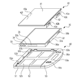
  • FIG. 3 illustrates three units that constitute the present embodiment.
  • Reference numeral 30 denotes a radiographic imaging apparatus, which includes a radiation detector inside a housing that is formed to have a standard size of a cassette as in the case with the first embodiment.
  • a manipulating portion 33, a status display 34, and a wireless communication path 35 are disposed together on a side surface 32b, which is one of side surfaces of the housing.
  • grooves 36a and 36b used to secure the radiographic imaging apparatus 30 to a handle portion 50 are provided on a side surface 32a, which is perpendicular to the side surface 32b.
  • the handle portion 50 includes a frame 51 formed of a pipe material so as to cover a side periphery of the radiographic imaging apparatus 30, a rear panel 52 provided on a rear surface side of a radiation incidence surface of the radiographic imaging apparatus 30, and a grip portion 53 having a through hole 53a.
  • a buffering effect which makes lateral shock be less transmittable to the radiographic imaging apparatus 30, can be achieved.
  • the buffering effect can be further improved by filling a material having a good buffering property in the hollow portion of the pipe and by coating the surface of the pipe with a material having a good buffering property.
  • the rear panel 52 is secured to the frame 51 at bent protrusions such as protrusions 52a to 52e.
  • Protrusions 54a and 54b movable in the Y-direction are inserted into the grooves 36b and 36a provided in the opposing side surface in order to secure the radiographic imaging apparatus 30 so as to prevent the radiographic imaging apparatus 30 from moving out of the frame 51 in the Z-direction.
  • the grip portion 53 includes the protrusions 54a and 54b for locking disposed therein.
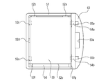
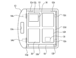
  • the protrusions 54a and 54b for locking are movable with slide portions 55a and 55b for manipulation provided on the surface side of the grip portion 53. This state, in which only the radiographic imaging apparatus 30 is attached to the handle portion 50, is illustrated in Fig. 5 as seen from the radiation incidence surface side and in Fig. 6 as seen from the rear surface side.
  • the radiographic imaging apparatus 30 is unevenly arranged in a receiving space formed by the frame 51 and the grip portion 53 so as to form a space 56 on the side surface 32b side where the manipulating portion 33, the status display 34, and the wireless communication path 35 are arranged.
  • This structure by uniformly covering the periphery of the radiographic imaging apparatus 30 without any cutout portions, protects the radiographic imaging apparatus 30 against lateral shock.
  • This structure can also ensure a space to allow access to the manipulating portion 33, a space to facilitate a visual check of the status display, and a space unlikely to interfere with radio communication.
  • the radiographic imaging apparatus 30 includes a battery 38 and a second wireless communication path 39 on the rear surface side.
  • the handle portion 50 has a plurality of openings including openings 52h and 52j formed in the rear panel 52.
  • openings 52h and 52j formed in the rear panel 52.
  • a door portion is formed in the bottom of the depression of the handle portion 50. The door portion permits the battery 38 to be removably attached to the handle portion 50.
  • An opening for performing wireless communication is also formed.
  • this structure permits the rear surface of the radiographic imaging apparatus 30 to be directly exposed, there is no degradation of heat dissipation performance of the radiographic imaging apparatus 30.
  • a grid portion 40 includes a frame 42 attached to a rear surface side of a grid body 41.
  • the frame 42 is provided with protrusions 42a, 42b, 42e, and 42f. Since the frame 42 is provided closer to the rear surface side than the grid is, edges of the frame 42 do not directly contact an examinee.
  • Engaging holes 42c and 42d are formed in the protrusions 42a and 42b so as to face the grooves 36b and 36a of the radiographic imaging apparatus 30.
  • the protrusions 42e and 42f which are provided at the opposite side of the frame 42, have a shape where tops of the protrusions 42e and 42f are obtusely bent.
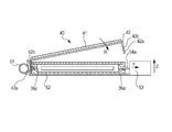
  • the protrusions 42e and 42f are, as illustrated in Fig. 7, inserted into the frame 51 at positions between the protrusions 52c and 52e of the handle portion 50 so as to be hooked to the frame 51.
  • the grid portion 40 is inclined in the direction indicated by the arrow R in the figure so as to align the protrusions 42a and 42b with the grooves 36b and 36a of the radiographic imaging apparatus 30.
  • the protrusions 54a and 54b for locking are moved so as to be passed through the holes 42c and 42d of the grid portion 40 and the grooves 36b and 36a of the radiographic imaging apparatus 30.
  • a change between states can be easily performed, that is, from a state in which only the radiographic imaging apparatus 30 is attached to the handle portion 50 to another state in which both the radiographic imaging apparatus 30 and the grid portion 40 are attached to the handle portion 50.

Landscapes

  • Physics & Mathematics (AREA)
  • General Physics & Mathematics (AREA)
  • Apparatus For Radiation Diagnosis (AREA)
  • Measurement Of Radiation (AREA)
  • Radiography Using Non-Light Waves (AREA)

Abstract

A container apparatus that is able to contain a radiographic imaging apparatus having a rectangular parallelepiped shape. The container apparatus includes a container portion into which the radiographic imaging apparatus is insertable in a direction perpendicular to a radiation detecting surface of the radiographic imaging apparatus and a protecting member that covers side surfaces of the radiographic imaging apparatus contained in the container portion, the side surfaces of the radiographic imaging apparatus being adjacent to the radiation detecting surface. The container apparatus also includes a holding portion that engages with the radiographic imaging apparatus contained in the container portion in order to hold the radiographic imaging apparatus in the container portion.

Description

CONTAINER APPARATUS
The present invention relates to a container apparatus that contains a radiographic imaging apparatus.
To date in general, radiographic imaging apparatuses that detect radiation rays radiated to and transmitted through objects are widely used. Such image taking has generally been performed with the film-screen method or the computed radiography (CR) method. In either of the above methods, a container case, which is standardized as a cassette, is used in taking an image. The container case contains a photographic sensitive film or a phosphor plate that stores an image as a latent image.
Recently, a digital radiography (DR) method, in which a radiographic image is taken and digitized using semiconductor sensors, has also been developed. This method has been in practical use in portable radiographic imaging apparatuses. However, since the radiographic imaging apparatus using the DR method includes a number of electronic components therein, the DR method radiographic imaging apparatus is heavy compared to a related art radiographic imaging apparatus using the cassette method despite efforts that have been made to make the DR method radiographic imaging apparatus lighter.
PTL 1 discloses a cassette carrier into which a radiographic imaging apparatus is inserted in a direction parallel to a radiation detecting surface.
The radiographic imaging apparatus is inserted into the cassette carrier disclosed in PTL 1 in the direction parallel to the radiation detecting surface. Since such a cassette carrier is constructed so as to cover the radiation detecting surface of the radiographic imaging apparatus, the cassette carrier becomes heavy in weight and portability thereof is reduced.
Also in this cassette carrier, since a side surface adjacent to the radiation detecting surface is narrow in width, there is a possibility that the radiographic imaging apparatus is damaged when it is subject to external shock. The cassette carrier having an exposed side surface does not sufficiently protect the radiation detecting surface against external shock.
Japanese Patent Laid-Open No. 10-282598
The present invention has been made in consideration of the above situation, and has as its object to eliminate the above problems and ensure both portability and rigidity of the radiographic imaging apparatus.
According to the present invention, the foregoing object is attained by providing a container apparatus that is able to contain a radiographic imaging apparatus having a rectangular parallelepiped shape. The container apparatus includes a container portion into which the radiographic imaging apparatus is insertable in a direction perpendicular to a radiation detecting surface of the radiographic imaging apparatus and a protecting member that covers side surfaces of the radiographic imaging apparatus contained in the container portion, the side surfaces of the radiographic imaging apparatus being adjacent to the radiation detecting surface. The container apparatus also includes a holding portion that engages with the radiographic imaging apparatus contained in the container portion in order to hold the radiographic imaging apparatus in the container portion.
Other features and advantages of the present invention will be apparent from the following description taken in conjunction with the accompanying drawings, in which like reference characters designate the same or similar parts throughout the figures thereof.
The accompanying drawings, which are incorporated in and constitute a part of the specification, illustrate embodiments of the invention and, together with the description, serve to explain the principles of the invention.
Fig. 1 is a schematic diagram illustrating a general configuration of a radiographic imaging apparatus in a first embodiment. Fig. 2 is a side sectional view of the radiographic imaging apparatus in the first embodiment. Fig. 3 is a schematic diagram illustrating a general configuration of a radiographic imaging apparatus in a second embodiment. Fig. 4 is a side sectional view illustrating the radiographic imaging apparatus of the second embodiment. Fig. 5 is a front view illustrating the radiographic imaging apparatus in the second embodiment. Fig. 6 is a back view illustrating the radiographic imaging apparatus in the second embodiment. Fig. 7 is a schematic diagram describing how a grid portion is attached in the second embodiment.
Preferred embodiments of the present invention will be described in detail in accordance with the accompanying drawings.
First Embodiment
A radiographic imaging apparatus in a first embodiment will be described with reference to Fig. 1.
Fig. 1 illustrates three units that constitute the present embodiment. The radiographic imaging apparatus 1 has a rectangular parallelepiped shape similar to a cassette and includes a radiation detector, wireless circuitry, and a battery, which are not shown, inside a cover 2 provided on a radiation incidence surface side and a housing 3 of the radiographic imaging apparatus 1.
A manipulating portion 4, which includes functions such as those of a power switch and a status display 5 for displaying a state of the radiographic imaging apparatus 1, is provided in a side surface 3a, which is one of side surfaces of the housing 3 and perpendicular to a surface of the cover 2. A wireless communication path 6, which is formed of a resin or other material having a radio transmissive property for wireless communication, is formed in a side surface 3b, which is another side surface of the housing 3. A grid portion 10 is formed so as to cover the radiographic imaging apparatus 1 from the radiation incidence surface side.
The grid portion 10 includes a grid body 11 for eliminating scattered radiation and a frame member 12. The frame member 12 is attached onto a rear surface side of a radiation incidence surface of the grid body 11. The frame member 12 includes openings 13 and 14 formed in side surfaces 12a and 12b thereof at positions corresponding to those of the manipulating portion 4, the status display 5, and the wireless communication path 6 provided on the side surfaces of the radiographic imaging apparatus 1.
A handle portion 20 is provided as a removable unit externally to the radiographic imaging apparatus 1 in order to provide portability to the radiographic imaging apparatus 1. The handle portion 20 includes a depression structure formed by connecting a frame 21 that covers the side periphery of the radiographic imaging apparatus 1 to a rear panel 22 provided on a rear surface side opposite the radiation incidence surface of the radiographic imaging apparatus 1. The handle portion 20 functions as a container apparatus provided with a container portion that can contain the radiographic imaging apparatus 1. The radiographic imaging apparatus 1 can be inserted into the container portion of the handle portion 20 in a direction perpendicular to a radiation detecting surface of the radiographic imaging apparatus 1. The handle portion 20 also functions as a protecting member that protects side surfaces of the radiographic imaging apparatus 1 which are adjacent to the radiation detecting surface.
The handle portion 20 is provided with a grip portion 23 for manipulation, which is secured therealong. The grip portion 23 has a through hole 23a formed therein to be of a shape that permits an operator to grip the grip portion 23. As illustrated in Fig. 2, the frame 21 is formed to be of a size sufficient to contain the radiographic imaging apparatus 1 with the grid portion 10 attached thereto. The frame 21 includes protrusions 25a and 25b formed on a side surface 21b side thereof. Grooves 7a and 7b are provided in the side surface 3b of the radiographic imaging apparatus 1, and holes 15a and 15b are provided in the grid portion 10 so as to correspond to the protrusions 25a and 25b. The protrusions 25a and 25b respectively penetrate through the holes 15a and 15b of the grid portion 10 and are inserted into the grooves 7a and 7b of the radiographic imaging apparatus 1. This prevents the radiographic imaging apparatus 1 from moving out the frame 21 in a Z-direction in Fig. 2. In contrast, the frame 21 includes protrusions 26a and 26b for locking formed in a side surface opposite the side surface 21b. The protrusions 26a and 26b function as holding portions and are movable in a Y-direction. The protrusions 26a and 26b are disposed in the grip portion 23 and are movable using a slide portion 27 for manipulation. Initially, the radiographic imaging apparatus 1 and the grid portion 10 are inserted into the handle portion 20 from the same side as that at which the protrusions 25a and 25b are located. The radiographic imaging apparatus 1 and the grid portion 10 are inclined and further inserted into the handle portion 20, and finally are locked by insertion of the protrusions 26a and 26b thereinto.
Such a structure can improve mechanical strength by covering the periphery of the radiographic imaging apparatus 1 with the grid portion 10 and the handle portion 20. This is advantageous in protecting the expensive radiographic imaging apparatus 1 since there is a possibility that the radiographic imaging apparatus 1 may be dropped or struck while it is being transported. In particular, when an image is being taken during a ward round or the like in a hospital, sometimes the radiographic imaging apparatus 1 located under an examinee lying in bed is moved into and out of position. In such a case, even if a load is applied in the Z-direction as illustrated in Fig. 2, this structure can sufficiently withstand the load because of the rear panel 22 disposed on the rear surface side. To suppress damage to the functions and performance of the status display 5, the manipulating portion 4, and the wireless communication path 6 provided in the radiographic imaging apparatus 1, such damage being caused by covering the periphery of the radiographic imaging apparatus 1, openings corresponding to those portions are provided. In addition, by providing a locking mechanism on the grip portion 23 side of the handle portion 20, the distances between an image taking area of the radiographic imaging apparatus 1 and the outer shape of the handle portion 20 can be minimized at the other three side surfaces of the handle portion 20. As described above, the locking mechanism functions as a controlling portion that controls engagement of the holding portions. This permits image taking with the three sides moved close to a desired region.
Second Embodiment
A second embodiment will be described with reference to Figs. 3 to 7. Fig. 3 illustrates three units that constitute the present embodiment. Reference numeral 30 denotes a radiographic imaging apparatus, which includes a radiation detector inside a housing that is formed to have a standard size of a cassette as in the case with the first embodiment. Unlike the first embodiment, a manipulating portion 33, a status display 34, and a wireless communication path 35 are disposed together on a side surface 32b, which is one of side surfaces of the housing. In addition, grooves 36a and 36b used to secure the radiographic imaging apparatus 30 to a handle portion 50 are provided on a side surface 32a, which is perpendicular to the side surface 32b.
The handle portion 50 includes a frame 51 formed of a pipe material so as to cover a side periphery of the radiographic imaging apparatus 30, a rear panel 52 provided on a rear surface side of a radiation incidence surface of the radiographic imaging apparatus 30, and a grip portion 53 having a through hole 53a. By using the pipe material, a buffering effect, which makes lateral shock be less transmittable to the radiographic imaging apparatus 30, can be achieved. The buffering effect can be further improved by filling a material having a good buffering property in the hollow portion of the pipe and by coating the surface of the pipe with a material having a good buffering property. The rear panel 52 is secured to the frame 51 at bent protrusions such as protrusions 52a to 52e. By connecting the frame 51 to the rear panel 52, mechanical strength against distortion, bending, and so forth is improved. Out of the protrusions of the frame 51, as illustrated in Fig. 4, top portions of the protrusions 52c and 52e are bent so as to be inserted into a groove 36c provided in the radiographic imaging apparatus 30 when the handle portion 50 is attached to the radiographic imaging apparatus 30.
Protrusions 54a and 54b movable in the Y-direction are inserted into the grooves 36b and 36a provided in the opposing side surface in order to secure the radiographic imaging apparatus 30 so as to prevent the radiographic imaging apparatus 30 from moving out of the frame 51 in the Z-direction. The grip portion 53 includes the protrusions 54a and 54b for locking disposed therein. The protrusions 54a and 54b for locking are movable with slide portions 55a and 55b for manipulation provided on the surface side of the grip portion 53. This state, in which only the radiographic imaging apparatus 30 is attached to the handle portion 50, is illustrated in Fig. 5 as seen from the radiation incidence surface side and in Fig. 6 as seen from the rear surface side. The radiographic imaging apparatus 30 is unevenly arranged in a receiving space formed by the frame 51 and the grip portion 53 so as to form a space 56 on the side surface 32b side where the manipulating portion 33, the status display 34, and the wireless communication path 35 are arranged. This structure, by uniformly covering the periphery of the radiographic imaging apparatus 30 without any cutout portions, protects the radiographic imaging apparatus 30 against lateral shock. This structure can also ensure a space to allow access to the manipulating portion 33, a space to facilitate a visual check of the status display, and a space unlikely to interfere with radio communication. By arranging those components and the space on one side surface side, the distances between the image taking area of the radiographic imaging apparatus 30 and the outer shape of the handle portion 50 can be minimized at one of the short sides and at one of the long sides. Thus, it is unlikely that image taking is obstructed. The radiographic imaging apparatus 30 includes a battery 38 and a second wireless communication path 39 on the rear surface side. The handle portion 50 has a plurality of openings including openings 52h and 52j formed in the rear panel 52. For example, a door portion is formed in the bottom of the depression of the handle portion 50. The door portion permits the battery 38 to be removably attached to the handle portion 50. An opening for performing wireless communication is also formed.
This can facilitate attaching of the battery 38, ensure wireless communication paths 39, and achieve the lightweight handle portion 50. In addition, since this structure permits the rear surface of the radiographic imaging apparatus 30 to be directly exposed, there is no degradation of heat dissipation performance of the radiographic imaging apparatus 30.
As illustrated in Fig. 3, a grid portion 40 includes a frame 42 attached to a rear surface side of a grid body 41. The frame 42 is provided with protrusions 42a, 42b, 42e, and 42f. Since the frame 42 is provided closer to the rear surface side than the grid is, edges of the frame 42 do not directly contact an examinee. Engaging holes 42c and 42d are formed in the protrusions 42a and 42b so as to face the grooves 36b and 36a of the radiographic imaging apparatus 30. The protrusions 42e and 42f, which are provided at the opposite side of the frame 42, have a shape where tops of the protrusions 42e and 42f are obtusely bent. The protrusions 42e and 42f are, as illustrated in Fig. 7, inserted into the frame 51 at positions between the protrusions 52c and 52e of the handle portion 50 so as to be hooked to the frame 51. The grid portion 40 is inclined in the direction indicated by the arrow R in the figure so as to align the protrusions 42a and 42b with the grooves 36b and 36a of the radiographic imaging apparatus 30. In so doing, the protrusions 54a and 54b for locking are moved so as to be passed through the holes 42c and 42d of the grid portion 40 and the grooves 36b and 36a of the radiographic imaging apparatus 30. As described above, in the present embodiment, a change between states can be easily performed, that is, from a state in which only the radiographic imaging apparatus 30 is attached to the handle portion 50 to another state in which both the radiographic imaging apparatus 30 and the grid portion 40 are attached to the handle portion 50.
While the present invention has been described with reference to exemplary embodiments, it is to be understood that the invention is not limited to the disclosed exemplary embodiments. The scope of the following claims is to be accorded the broadest interpretation so as to encompass all such modifications and equivalent structures and functions.
This application claims the benefit of Japanese Patent Application No. 2009-270094, filed November 27, 2009, which is hereby incorporated by reference herein in its entirety.

Claims (10)

  1. A container apparatus that is able to contain a radiographic imaging apparatus having a rectangular parallelepiped shape, the container apparatus comprising:
    a container portion into which the radiographic imaging apparatus is insertable in a direction perpendicular to a radiation detecting surface of the radiographic imaging apparatus;
    a protecting member that covers side surfaces of the radiographic imaging apparatus contained in the container portion, the side surfaces of the radiographic imaging apparatus being adjacent to the radiation detecting surface; and
    a holding portion that engages with the radiographic imaging apparatus contained in the container portion in order to hold the radiographic imaging apparatus in the container portion.
  2. The container apparatus according to Claim 1, further comprising:
    a grid portion that is removably attached to the container apparatus and covers the radiation detecting surface of the radiographic imaging apparatus contained in the container portion.
  3. The container apparatus according to Claim 2, wherein the engagement of the holding portion with the radiographic imaging apparatus holds the grid portion in the container portion.
  4. The container apparatus according to Claim 1, wherein the protecting member has an opening for manipulating a manipulating portion of the radiographic imaging apparatus contained in the container portion.
  5. The container apparatus according to Claim 1, wherein the protecting member has an opening for displaying with a display portion of the radiographic imaging apparatus contained in the container portion.
  6. The container apparatus according to Claim 1, further comprising:
    a grip portion that is removably attached to the container portion for transporting the radiographic imaging apparatus contained in the container portion.
  7. The container apparatus according to Claim 6, further comprising:
    a controlling portion provided in the grip portion, the controlling portion controlling the engagement of the holding portion with the radiographic imaging apparatus.
  8. The container apparatus according to Claim 1, wherein the container portion is formed in a depression that covers the radiographic imaging apparatus contained in the container portion.
  9. The container apparatus according to Claim 8, wherein an opening for wireless communication of the radiographic imaging apparatus is formed in a bottom portion of the depression of the container portion.
  10. The container apparatus according to Claim 8, wherein a door portion for removing and attaching a battery of the radiographic imaging apparatus is formed in a bottom portion of the depression of the container portion.
PCT/JP2010/006845 2009-11-27 2010-11-24 Container apparatus Ceased WO2011064987A1 (en)

Priority Applications (2)

Application Number Priority Date Filing Date Title
US13/512,089 US8916844B2 (en) 2009-11-27 2010-11-24 Container apparatus
CN201080053330.7A CN102640053B (en) 2009-11-27 2010-11-24 Container apparatus

Applications Claiming Priority (2)

Application Number Priority Date Filing Date Title
JP2009270094A JP5562012B2 (en) 2009-11-27 2009-11-27 Storage device
JP2009-270094 2009-11-27

Publications (1)

Publication Number Publication Date
WO2011064987A1 true WO2011064987A1 (en) 2011-06-03

Family

ID=43648755

Family Applications (1)

Application Number Title Priority Date Filing Date
PCT/JP2010/006845 Ceased WO2011064987A1 (en) 2009-11-27 2010-11-24 Container apparatus

Country Status (4)

Country Link
US (1) US8916844B2 (en)
JP (1) JP5562012B2 (en)
CN (1) CN102640053B (en)
WO (1) WO2011064987A1 (en)

Cited By (1)

* Cited by examiner, † Cited by third party
Publication number Priority date Publication date Assignee Title
US9006671B2 (en) 2011-09-28 2015-04-14 Fujifilm Corporation Radiological image detection apparatus

Families Citing this family (6)

* Cited by examiner, † Cited by third party
Publication number Priority date Publication date Assignee Title
CN103455110A (en) * 2012-06-01 2013-12-18 鸿富锦精密工业(深圳)有限公司 Server tray
JP6050201B2 (en) * 2013-09-09 2016-12-21 富士フイルム株式会社 Electronic cassette
KR102043176B1 (en) * 2018-03-06 2019-11-12 주식회사 뷰웍스 A Handle for radiation detectors
JP7224993B2 (en) * 2019-03-27 2023-02-20 キヤノン株式会社 radiography equipment
JP7327977B2 (en) * 2019-04-04 2023-08-16 キヤノン株式会社 radiography equipment
US20250321343A1 (en) * 2024-04-16 2025-10-16 GE Precision Healthcare LLC Methods and systems for x-ray detector flash memory

Citations (7)

* Cited by examiner, † Cited by third party
Publication number Priority date Publication date Assignee Title
EP0632320A1 (en) * 1993-06-30 1995-01-04 Eastman Kodak Company Film cassette
US5773839A (en) * 1994-03-31 1998-06-30 Imation Corp. Cassette for use in an electronic radiographic imaging system
JPH10282598A (en) 1997-04-08 1998-10-23 Okamoto Seisakusho:Kk Cassette carrier for radiation
WO2007139638A2 (en) * 2006-05-26 2007-12-06 Carestream Health, Inc. Encasement for digital radiography detector
FR2914433A1 (en) * 2007-03-30 2008-10-03 Gen Electric SYSTEM AND METHOD FOR ELECTRICALLY POWERING AN X-RAY WIRELESS DETECTOR
JP2009270094A (en) 2008-05-08 2009-11-19 Samsung Electronics Co Ltd New thermoplastic elastomer-resin array composition and its manufacturing method
EP2229889A1 (en) * 2009-03-16 2010-09-22 Carestream Health, Inc. Tray for portable digital radiography cassette

Family Cites Families (18)

* Cited by examiner, † Cited by third party
Publication number Priority date Publication date Assignee Title
JPS5883840A (en) * 1981-11-14 1983-05-19 Fuji Photo Film Co Ltd Accumulation type phosphor sheet and structure body consisting of cassette storing this sheet
JPH0724343Y2 (en) * 1989-08-31 1995-06-05 富士写真フイルム株式会社 Film magazine
US5804832A (en) * 1996-11-26 1998-09-08 Sterling Diagnostic Imaging, Inc. Digital array for radiographic imaging
US6344652B1 (en) * 1999-01-13 2002-02-05 Fuji Photo Film Co., Ltd. Radiation detecting cassette
JP2000275763A (en) * 1999-03-24 2000-10-06 Fuji Photo Film Co Ltd Cassette for stimulable phosphor sheet and its id recognition structure
US6744062B2 (en) * 2001-09-11 2004-06-01 Eastman Kodak Company Apparatus for radiographically imaging elongated objects
JP3870083B2 (en) * 2001-12-21 2007-01-17 キヤノン株式会社 Grid attachment / detachment mechanism of radiography equipment
JP4000587B2 (en) * 2002-01-10 2007-10-31 コニカミノルタホールディングス株式会社 Radiation imaging cassette and mammography cassette
JP3785372B2 (en) * 2002-02-25 2006-06-14 富士写真フイルム株式会社 Apparatus for detecting state of sheet-like image record carrier
JP2004177251A (en) 2002-11-27 2004-06-24 Canon Inc Radiation imaging equipment
JP3848288B2 (en) * 2003-04-25 2006-11-22 キヤノン株式会社 Radiation imaging equipment
JP2005258370A (en) * 2003-09-05 2005-09-22 Fuji Photo Film Co Ltd Radiation cassette
DE102004042365A1 (en) * 2003-09-12 2005-04-14 Siemens Ag X-ray detector e.g. CMOS chip, has detector plate with detector units accommodated in housing in floating manner using spring unit, where detector plate is attached to one of inside wall of housing and substrate
US7189972B2 (en) * 2004-10-04 2007-03-13 General Electric Company X-ray detector with impact absorbing cover
JP2007017674A (en) * 2005-07-07 2007-01-25 Konica Minolta Medical & Graphic Inc Cleaning method for image reading device, image reading device, and cassette for cleaning
US7429737B2 (en) * 2006-11-09 2008-09-30 Carestream Health, Inc. Retrofit digital mammography detector
JP2009053661A (en) * 2007-07-30 2009-03-12 Fujifilm Corp Radiation detection cassette and medical system
JP4914849B2 (en) * 2008-02-08 2012-04-11 富士フイルム株式会社 Radiation converter and radiation converter processing apparatus

Patent Citations (7)

* Cited by examiner, † Cited by third party
Publication number Priority date Publication date Assignee Title
EP0632320A1 (en) * 1993-06-30 1995-01-04 Eastman Kodak Company Film cassette
US5773839A (en) * 1994-03-31 1998-06-30 Imation Corp. Cassette for use in an electronic radiographic imaging system
JPH10282598A (en) 1997-04-08 1998-10-23 Okamoto Seisakusho:Kk Cassette carrier for radiation
WO2007139638A2 (en) * 2006-05-26 2007-12-06 Carestream Health, Inc. Encasement for digital radiography detector
FR2914433A1 (en) * 2007-03-30 2008-10-03 Gen Electric SYSTEM AND METHOD FOR ELECTRICALLY POWERING AN X-RAY WIRELESS DETECTOR
JP2009270094A (en) 2008-05-08 2009-11-19 Samsung Electronics Co Ltd New thermoplastic elastomer-resin array composition and its manufacturing method
EP2229889A1 (en) * 2009-03-16 2010-09-22 Carestream Health, Inc. Tray for portable digital radiography cassette

Cited By (1)

* Cited by examiner, † Cited by third party
Publication number Priority date Publication date Assignee Title
US9006671B2 (en) 2011-09-28 2015-04-14 Fujifilm Corporation Radiological image detection apparatus

Also Published As

Publication number Publication date
US20120280601A1 (en) 2012-11-08
JP5562012B2 (en) 2014-07-30
JP2011112921A (en) 2011-06-09
CN102640053A (en) 2012-08-15
CN102640053B (en) 2014-10-22
US8916844B2 (en) 2014-12-23

Similar Documents

Publication Publication Date Title
WO2011064987A1 (en) Container apparatus
JP5854700B2 (en) X-ray imaging apparatus, handle unit, and X-ray imaging unit
US10959691B2 (en) Electronic cassette
JP5650509B2 (en) Radiation cassette carrier and portable radiography apparatus
US10274613B2 (en) Radiation imaging apparatus and radiation imaging system
US20130077760A1 (en) Radiation imaging apparatus and detachable grid unit for same
CN110196447B (en) Radiation detection device
JP2015051206A (en) Electronic cassette
KR20120093350A (en) Radiograph
EP3097852A1 (en) Radiation image detector, and housing for radiation image detector
CN105662442B (en) Radiology Imaging System
JP2023054058A (en) radiography equipment
US20170311913A1 (en) Radiographing apparatus and radiographing system
JP2014020791A (en) Electronic cassette
JP2008129231A (en) Cassette type radiation image detector
US7909510B2 (en) Radiation photographing apparatus
JP5875663B2 (en) Radiation cassette carrier and portable radiographic apparatus
US8511893B2 (en) Packaging for a radiological device
JP2004212793A (en) Cassette for radiation image reading, combination of the same with radiation image radiographic cassette, radiation image translate panel repacking method, and radiation image reading method
JP2004212795A (en) Medical purpose cassette and image processing system
JP2010152133A (en) Cassette for photographing radiation image

Legal Events

Date Code Title Description
WWE Wipo information: entry into national phase

Ref document number: 201080053330.7

Country of ref document: CN

121 Ep: the epo has been informed by wipo that ep was designated in this application

Ref document number: 10798198

Country of ref document: EP

Kind code of ref document: A1

WWE Wipo information: entry into national phase

Ref document number: 13512089

Country of ref document: US

NENP Non-entry into the national phase

Ref country code: DE

122 Ep: pct application non-entry in european phase

Ref document number: 10798198

Country of ref document: EP

Kind code of ref document: A1