JP2005258370A - Radiation cassette - Google Patents

Radiation cassette Download PDF

Info

Publication number
JP2005258370A
JP2005258370A JP2004112006A JP2004112006A JP2005258370A JP 2005258370 A JP2005258370 A JP 2005258370A JP 2004112006 A JP2004112006 A JP 2004112006A JP 2004112006 A JP2004112006 A JP 2004112006A JP 2005258370 A JP2005258370 A JP 2005258370A
Authority
JP
Japan
Prior art keywords
radiation
lid
cassette
radiation cassette
stimulable phosphor
Prior art date
Legal status (The legal status is an assumption and is not a legal conclusion. Google has not performed a legal analysis and makes no representation as to the accuracy of the status listed.)
Pending
Application number
JP2004112006A
Other languages
Japanese (ja)
Other versions
JP2005258370A5 (en
Inventor
Yasuyoshi Ota
恭義 大田
Masakazu Nakajo
正和 中條
Current Assignee (The listed assignees may be inaccurate. Google has not performed a legal analysis and makes no representation or warranty as to the accuracy of the list.)
Fujifilm Holdings Corp
Original Assignee
Fuji Photo Film Co Ltd
Priority date (The priority date is an assumption and is not a legal conclusion. Google has not performed a legal analysis and makes no representation as to the accuracy of the date listed.)
Filing date
Publication date
Application filed by Fuji Photo Film Co Ltd filed Critical Fuji Photo Film Co Ltd
Priority to JP2004112006A priority Critical patent/JP2005258370A/en
Priority to US10/933,362 priority patent/US7556426B2/en
Publication of JP2005258370A publication Critical patent/JP2005258370A/en
Publication of JP2005258370A5 publication Critical patent/JP2005258370A5/ja
Pending legal-status Critical Current

Links

Images

Classifications

    • GPHYSICS
    • G03PHOTOGRAPHY; CINEMATOGRAPHY; ANALOGOUS TECHNIQUES USING WAVES OTHER THAN OPTICAL WAVES; ELECTROGRAPHY; HOLOGRAPHY
    • G03CPHOTOSENSITIVE MATERIALS FOR PHOTOGRAPHIC PURPOSES; PHOTOGRAPHIC PROCESSES, e.g. CINE, X-RAY, COLOUR, STEREO-PHOTOGRAPHIC PROCESSES; AUXILIARY PROCESSES IN PHOTOGRAPHY
    • G03C3/00Packages of films for inserting into cameras, e.g. roll-films, film-packs; Wrapping materials for light-sensitive plates, films or papers, e.g. materials characterised by the use of special dyes, printing inks, adhesives
    • GPHYSICS
    • G03PHOTOGRAPHY; CINEMATOGRAPHY; ANALOGOUS TECHNIQUES USING WAVES OTHER THAN OPTICAL WAVES; ELECTROGRAPHY; HOLOGRAPHY
    • G03BAPPARATUS OR ARRANGEMENTS FOR TAKING PHOTOGRAPHS OR FOR PROJECTING OR VIEWING THEM; APPARATUS OR ARRANGEMENTS EMPLOYING ANALOGOUS TECHNIQUES USING WAVES OTHER THAN OPTICAL WAVES; ACCESSORIES THEREFOR
    • G03B42/00Obtaining records using waves other than optical waves; Visualisation of such records by using optical means
    • G03B42/02Obtaining records using waves other than optical waves; Visualisation of such records by using optical means using X-rays
    • G03B42/04Holders for X-ray films

Abstract

<P>PROBLEM TO BE SOLVED: To smoothly load and unload an image recording carrier into and from a cassette with a compact and simple configurstion and to save an occupancy space. <P>SOLUTION: The radiation cassette 10 has a casing 14 for storing a stimulalbe phosphor plate 12 and a lid 16 openably and closably mounted on the casing 14. The lid 16 has a guide structure 20 for guiding the stimulable phosphor plate 12 when the stimulable phosphor plate 12 is removed or inserted while the lid 16 is open and held with respect to the casing 14. The guide structure 20 has claw parts 76a and 76b fixed to an inner surface 16a of the lid 16 and recesses that are defined in respective opposite side edges of the stimulable phosphor plate. <P>COPYRIGHT: (C)2005,JPO&NCIPI

Description

本発明は、被写体の放射線画像情報が記録されるプレート状の放射線画像記録担体を収容する放射線カセッテに関する。   The present invention relates to a radiation cassette that houses a plate-shaped radiation image record carrier on which radiation image information of a subject is recorded.

例えば、蓄積性蛍光体(輝尽性蛍光体)を利用して、人体等の被写体の放射線画像情報を一旦記録し、この放射線画像情報を写真フイルム等の写真感光材料等に再生し、あるいはCRT等に可視像として出力させるシステムが知られている。   For example, using a stimulable phosphor (stimulable phosphor), radiation image information of a subject such as a human body is temporarily recorded, and the radiation image information is reproduced on a photographic material such as a photographic film, or a CRT. For example, a system that outputs a visible image to the image is known.

蓄積性蛍光体は、放射線(X線、α線、β線、γ線、電子線、紫外線等)の照射によりこの放射線エネルギの一部を蓄積し、後に可視光等の励起光の照射によって、蓄積されたエネルギに応じて輝尽発光を示す蛍光体をいう。この蓄積性蛍光体は、通常、プレート状に構成されて蓄積性蛍光体プレートとして使用されている。   The stimulable phosphor accumulates a part of this radiation energy by irradiation with radiation (X-ray, α-ray, β-ray, γ-ray, electron beam, ultraviolet ray, etc.), and later by irradiation with excitation light such as visible light, A phosphor that exhibits stimulated emission according to the stored energy. This stimulable phosphor is usually formed in a plate shape and used as a stimulable phosphor plate.

一方、人体等の被写体に放射線、例えば、X線を照射してこの被写体の放射線画像情報を写真フイルムに直接記録する作業が行われている。そして、この写真フイルムに現像処理が施されることにより可視画像が得られ、この可視画像を使用して医療診断等がなされている。   On the other hand, radiation, for example, X-rays are applied to a subject such as a human body, and radiation image information of the subject is directly recorded on a photographic film. A visible image is obtained by developing the photographic film, and a medical diagnosis or the like is performed using the visible image.

上記の蓄積性蛍光体プレートや写真フイルム等の放射線画像記録担体は、通常、1枚ずつカセッテに収容された状態で撮影装置に装填され、このカセッテを通して前記放射線画像記録担体にX線が照射されている。この種のカセッテとして、例えば、特許文献1に開示されたカセッテが知られている。   Radiation image record carriers such as the above-mentioned stimulable phosphor plates and photographic films are usually loaded into an imaging apparatus in a state of being accommodated in cassettes one by one, and the radiation image record carriers are irradiated with X-rays through the cassettes. ing. As this type of cassette, for example, a cassette disclosed in Patent Document 1 is known.

図20に示すように、特許文献1のカセッテ1は、ケース半体2a、2bをビス止めして一体化されており、このカセッテ1の一端面には、開口3が形成されている。この開口3には、トレイ4が引き出し自在に配設されるとともに、前記トレイ4に放射線画像変換プレート5が固定されている。トレイ4には、開口3を閉塞可能なキャップ6が取り付けられている。   As shown in FIG. 20, the cassette 1 of Patent Document 1 is integrated by screwing case halves 2 a and 2 b, and an opening 3 is formed on one end surface of the cassette 1. A tray 4 is disposed in the opening 3 so as to be freely drawn out, and a radiation image conversion plate 5 is fixed to the tray 4. A cap 6 capable of closing the opening 3 is attached to the tray 4.

特開平11−271894号公報(図3)Japanese Patent Laid-Open No. 11-271894 (FIG. 3)

しかしながら、上記の特許文献1では、放射線画像変換プレート5が固定されているトレイ4に、キャップ6が設けられているため、前記トレイ4全体が重量物となっている。このため、カセッテ1が装填される放射線画像記録読取装置内において、該カセッテ1に対してトレイ4の着脱作業を行う着脱機構は、相当に大型且つ重量物となるという問題が指摘されている。   However, in Patent Document 1 described above, since the cap 6 is provided on the tray 4 to which the radiation image conversion plate 5 is fixed, the entire tray 4 is heavy. For this reason, it has been pointed out that the attachment / detachment mechanism for attaching / detaching the tray 4 to / from the cassette 1 in the radiation image recording / reading apparatus loaded with the cassette 1 is considerably large and heavy.

しかも、トレイ4は、カセッテ1の幅狭な開口3に挿入されるため、このトレイ4の挿入作業を正確に行わなければならない。これにより、高精度な着脱機構が必要になって、設備コストが高騰するという問題がある。   In addition, since the tray 4 is inserted into the narrow opening 3 of the cassette 1, the tray 4 must be inserted accurately. As a result, a highly accurate attachment / detachment mechanism is required, and there is a problem that the equipment cost increases.

本発明はこの種の問題を解決するものであり、コンパクト且つ簡単な構成で、カセッテに対する放射線画像記録担体の着脱作業が円滑に遂行されるとともに、省スペース化を図ることが可能な放射線カセッテを提供することを目的とする。   The present invention solves this type of problem, and provides a radiation cassette that can be mounted and removed smoothly with a compact and simple configuration and can save space. The purpose is to provide.

本発明に係る放射線カセッテでは、例えば、蓄積性蛍光体プレート等の放射線画像記録担体を収容する収容部と、前記収容部に開閉自在に装着される蓋体とを備え、前記蓋体又は前記収容部には、前記蓋体が前記収容部に対して開放された状態で、前記放射線画像記録担体の取り出し又は挿入を行う際に、前記放射線画像記録担体を案内するガイド構造が設けられている。   The radiation cassette according to the present invention includes, for example, a storage unit that stores a radiographic image record carrier such as a stimulable phosphor plate, and a lid that is openably and closably attached to the storage unit. The part is provided with a guide structure for guiding the radiographic image record carrier when the radiographic image record carrier is taken out or inserted in a state where the lid is opened with respect to the accommodating part.

ガイド構造は、放射線画像記録担体の取り出し又は挿入方向に延在し且つ互いに対向する一対の係合部を備え、前記係合部には、前記放射線画像記録担体の両側部がスライド自在に係合することが好ましい。   The guide structure includes a pair of engaging portions that extend in the direction of taking out or inserting the radiographic image record carrier and face each other, and the both sides of the radiographic image record carrier are slidably engaged with the engaging portion. It is preferable to do.

なお、係合部と放射線画像記録担体の両側部とは、一方を凸形状とし、他方を凹形状として係合させることができる。   Note that one of the engaging portion and both side portions of the radiographic image recording carrier can be engaged with each other with a convex shape and the other with a concave shape.

さらに、収容部と蓋体との間には、該蓋体の開放角度を規制するとともに、該規制を解除可能なストッパ構造が設けられることが好ましい。   Furthermore, it is preferable that a stopper structure that restricts the opening angle of the lid and releases the regulation is provided between the housing portion and the lid.

さらにまた、収容部と蓋体とは、ヒンジで連結されるとともに、前記収容部と前記蓋体とは、互いに嵌合する溝部及び突起部を有する合わせ構造により閉塞可能であることが好ましい。その際、合わせ構造は、シール部材を取り付けることが好ましい。   Furthermore, it is preferable that the housing portion and the lid body are connected by a hinge, and the housing portion and the lid body can be closed by a mating structure having a groove portion and a protrusion portion that are fitted to each other. In that case, it is preferable that a sealing member is attached to the mating structure.

また、蓋体の内面に配置される弾性体を備え、前記蓋体が収容部を閉塞する際、前記弾性体が放射線画像記録担体を放射線照射側である前記収容部の内面に向かって加圧保持することが好ましい。   In addition, an elastic body is provided on the inner surface of the lid, and when the lid closes the housing portion, the elastic body presses the radiation image recording carrier toward the inner surface of the housing portion on the radiation irradiation side. It is preferable to hold.

さらに、収容部の内部には、金属板又は金属複合板(例えば、金属とゴムやプラスチックの複合材)からなる散乱線除去用グリッドが配置されることが好ましい。   Furthermore, it is preferable that a scattered radiation removing grid made of a metal plate or a metal composite plate (for example, a composite material of metal and rubber or plastic) is disposed inside the housing portion.

さらにまた、少なくとも蓋体、収容部又は他のカセッテ構成部材のいずれかは、導電性を有することが好ましい。また、放射線カセッテは、抗菌材料や生分解性樹脂材料で構成され、又は抗菌処理が施されていることが好ましい。   Furthermore, it is preferable that at least one of the lid, the accommodating portion, and the other cassette constituent member has conductivity. Moreover, it is preferable that the radiation cassette is composed of an antibacterial material or a biodegradable resin material or is subjected to an antibacterial treatment.

さらに、蓋体には、筆記用具で繰り返し書き消し可能な筆記部が設けられることが好ましい。   Furthermore, it is preferable that the lid is provided with a writing portion that can be repeatedly written with a writing tool.

さらにまた、収容部は、エネルギサブトラクション処理を行うための2枚の前記放射線画像記録担体を重畳させて収容し、前記ガイド構造は、前記各放射線画像記録担体を取り出し又は挿入すべく案内するように構成することができる。   Still further, the accommodating portion accommodates two of the radiographic image record carriers for performing energy subtraction processing, and the guide structure guides the radiographic image record carriers to be taken out or inserted. Can be configured.

本発明によれば、ガイド構造の案内作用下に、放射線画像記録担体が蓋体又は収容部に沿って円滑且つ確実に移動することができる。このため、蓋体が収容部に対して比較的小さな角度だけ開放されていても、放射線画像記録担体が前記蓋体や前記収容部に接触することがなく、前記放射線画像記録担体の取り出し及び/又は挿入が良好に行われる。これにより、蓋体を開閉するためのスペースが削減され、カセッテ装填装置内の省スペース化が容易に図られるとともに、放射線画像記録担体の損傷を可及的に阻止することが可能になる。   According to the present invention, the radiographic image record carrier can smoothly and reliably move along the lid or the accommodating portion under the guiding action of the guide structure. For this reason, even if the lid is opened at a relatively small angle with respect to the accommodating portion, the radiographic image record carrier does not come into contact with the lid or the accommodating portion, and the radiation image record carrier can be taken out and / or removed. Or the insertion is done well. Thereby, the space for opening and closing the lid is reduced, the space in the cassette loading device can be easily saved, and damage to the radiation image record carrier can be prevented as much as possible.

また、ガイド構造は、蓋体又は収容部に設けられた一対の係合部を備えており、このガイド構造の簡素化が容易に図られるとともに、放射線画像記録担体を確実に案内することができる。   Further, the guide structure includes a pair of engaging portions provided in the lid or the housing portion, and the guide structure can be easily simplified and the radiation image record carrier can be reliably guided. .

さらに、収容部と蓋体とは、ストッパ構造を介して開放角度が規制されるため、カセッテ装填装置内に特別の開度規制機構を設ける必要がない。従って、カセッテ装填装置を経済的に構成することが可能になるとともに、規制を解除することによって蓋体が大きく開放されるため、カセッテ内のメンテナンスが容易に行われる。   Furthermore, since the opening angle of the housing portion and the lid body is regulated via the stopper structure, it is not necessary to provide a special opening degree regulating mechanism in the cassette loading device. Therefore, the cassette loading device can be configured economically, and the lid body is largely opened by releasing the regulation, so that maintenance inside the cassette is easily performed.

さらにまた、ヒンジを用いるとともに、互いに嵌合する溝部及び突起部を有する合わせ構造を採用することにより、かぶりを防止することができ、さらにシール部材を取り付けることにより防水性が有効に向上して、例えば、消毒液がカセッテ内に浸入することを防止することができる。   Furthermore, by using a hinge and a mating structure having a groove and a protrusion that fit together, it is possible to prevent fogging, and by attaching a seal member, the waterproofness is effectively improved, For example, it is possible to prevent the disinfectant from entering the cassette.

また、蓋体が収容部側に閉動してこの収容部内を閉塞する際には、放射線画像記録担体が弾性体の押圧作用下に前記収容部の内面に向かって加圧される。このため、放射線画像記録担体は、その撮影面が収容部の内面(放射線照射面)に密着するように押圧され、前記放射線画像記録担体に被写体の放射線画像情報を高品質に撮影することが可能になる。   Further, when the lid is closed to the housing portion side to close the inside of the housing portion, the radiographic image record carrier is pressed toward the inner surface of the housing portion under the pressing action of the elastic body. For this reason, the radiographic image record carrier is pressed so that its imaging surface is in close contact with the inner surface (radiation irradiation surface) of the housing portion, and radiographic image information of the subject can be imaged with high quality on the radiographic image record carrier. become.

さらにまた、収容部内部に配置された金属板又は金属複合板からなる散乱線除去用グリッドに放射線画像記録担体が押し付けられるため、前記放射線画像記録担体の撮影面に対する密着性が向上し、撮影画像の品質を有効にさせることができる。これにより、特に、リニアック(放射線治療)の場合に好適に採用することが可能になる。   Furthermore, since the radiographic image record carrier is pressed against the scattered radiation removing grid made of a metal plate or a metal composite plate arranged inside the accommodating portion, the adhesion of the radiographic image record carrier to the imaging surface is improved, and the captured image is improved. Can be made effective. Thereby, it becomes possible to employ | adopt suitably especially in the case of a linac (radiotherapy).

また、放射線カセッテの構成部材が導電性を有するため、静電気の発生を阻止して放射線画像記録担体への悪影響を防止することができる。さらに、放射線カセッテは、抗菌効果を有するため、衛生管理が簡素化する。   Further, since the constituent members of the radiation cassette have conductivity, the generation of static electricity can be prevented and adverse effects on the radiation image record carrier can be prevented. Furthermore, since the radiation cassette has an antibacterial effect, hygiene management is simplified.

さらに、放射線カセッテを生分解性樹脂材料とすることにより、環境を考慮した放射線カセッテの廃棄処理が可能となる。   Furthermore, by using a radiation cassette as a biodegradable resin material, it becomes possible to dispose of the radiation cassette in consideration of the environment.

さらにまた、蓋体に設けられる筆記部には、筆記用具で種々の情報を繰り返し書き消しすることが可能になり、作業性の向上が図られる。   Furthermore, it becomes possible to repeatedly erase various information with a writing tool in the writing section provided on the lid, and workability is improved.

さらに、放射線カセッテに2枚の放射線画像記録担体を重畳させて収容可能とすることにより、エネルギサブトラクション処理に適用できる放射線カセッテを提供することができる。   Furthermore, the radiation cassette applicable to the energy subtraction process can be provided by allowing the radiation cassette to be accommodated by superimposing two radiation image record carriers.

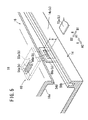
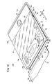
図1は、本発明の実施形態に係る放射線カセッテ10の斜視説明図である。   FIG. 1 is an explanatory perspective view of a radiation cassette 10 according to an embodiment of the present invention.

放射線カセッテ10は、蓄積性蛍光体プレート(放射線画像記録担体)12を収容し放射線照射面を構成する収容部14と、前記収容部14の一方の端部14aを支点にして開閉自在に装着される蓋体16とを備える。収容部14の端部14aと蓋体16とは、樹脂ヒンジ18を介して揺動自在に連結される。蓋体16には、該蓋体16が収容部14に対して開放された状態で、蓄積性蛍光体プレート12の取り出し及び挿入時に該蓄積性蛍光体プレート12を案内するガイド構造20が設けられる。   The radiation cassette 10 is mounted so as to be openable and closable with a storage portion 14 that contains a stimulable phosphor plate (radiation image record carrier) 12 and that constitutes a radiation irradiation surface, and one end portion 14a of the storage portion 14 as a fulcrum. And a lid body 16. The end portion 14 a of the housing portion 14 and the lid body 16 are slidably connected via a resin hinge 18. The lid 16 is provided with a guide structure 20 that guides the stimulable phosphor plate 12 when the stimulable phosphor plate 12 is taken out and inserted in a state where the lid 16 is opened with respect to the accommodating portion 14. .

なお、収容部14と蓋体16とは、一方に配設したピン部材を他方に形成した孔部に嵌合させる構成として、蓋体16を収容部14に対して開閉自在とすることができる。また、収容部14と蓋体16とを一体構成とし、収容部14に連結される部分での蓋体16の可撓性を利用して開閉自在とすることもできる。   In addition, the accommodating part 14 and the cover body 16 can make the cover body 16 openable and closable with respect to the accommodating part 14 as a structure which fits the pin member arrange | positioned in one to the hole formed in the other. . In addition, the housing portion 14 and the lid body 16 can be integrated, and can be opened and closed using the flexibility of the lid body 16 at the portion connected to the housing portion 14.

収容部14の他方の端部14bには、蓄積性蛍光体プレート12の挿入及び取り出しを行うための開口部22が形成されるとともに、この開口部22の両側には、後述する蓋体ロック手段24を解除するための押圧ピン挿入用孔部26a、26bが形成される。   An opening 22 for inserting and removing the stimulable phosphor plate 12 is formed at the other end 14b of the accommodating portion 14, and lid body locking means to be described later is formed on both sides of the opening 22 Press pin insertion holes 26a and 26b for releasing 24 are formed.

図2に示すように、蓋体ロック手段24は、収容部14に固定される固定ブロック30a、30bを備え、前記固定ブロック30a、30bには、スプリング32a、32bの一端が係合するとともに、前記スプリング32a、32bの他端側が、スライダ34a、34bに形成された孔部36a、36bに挿入される。スライダ34a、34bの先端には、収容部14の孔部26a、26bに挿入自在な円柱状のピン当接部38a、38bが設けられるとともに、前記ピン当接部38a、38bから後方(矢印A1方向)に所定距離だけ離間して下側ロック爪40a、40bが膨出形成される。   As shown in FIG. 2, the lid locking means 24 includes fixed blocks 30 a and 30 b fixed to the accommodating portion 14, and one ends of springs 32 a and 32 b are engaged with the fixed blocks 30 a and 30 b, The other ends of the springs 32a and 32b are inserted into holes 36a and 36b formed in the sliders 34a and 34b. Cylindrical pin contact portions 38a and 38b that can be inserted into the holes 26a and 26b of the accommodating portion 14 are provided at the tips of the sliders 34a and 34b, and rearward (arrow A1) from the pin contact portions 38a and 38b. The lower lock claws 40a and 40b are bulged and spaced apart by a predetermined distance in the direction).

図1に示すように、蓋体16には、バーコード読み取り用窓部44が形成されるとともに、この窓部44の両側には蓋体ロック手段24を構成するロック解除用ノブ46a、46bがスプリング48a、48bを介して前方(矢印A2方向)に押圧されている(図2参照)。   As shown in FIG. 1, a barcode reading window 44 is formed on the lid 16, and unlocking knobs 46 a and 46 b constituting the lid locking means 24 are provided on both sides of the window 44. It is pressed forward (arrow A2 direction) via the springs 48a and 48b (see FIG. 2).

なお、バーコード読み取り用窓部44からは、放射線カセッテ10に収容された蓄積性蛍光体プレート12に記録された図示しないバーコードの読み取りが行われる。バーコードには、蓄積性蛍光体プレート12の識別番号等が記録されている。バーコードに代えて、RFID(Radio Frequency Identification)等のICチップを蓄積性蛍光体プレート12に装着し、このICチップに識別番号、患者情報、撮影情報等を記憶させておくこともできる。この場合、バーコード読み取り用窓部44は不要であり、また、非接触での情報の読み取りができるため、蓄積性蛍光体プレート12に対するICチップの配置の自由度もバーコードに比較して格段に高くなる。   Note that a barcode (not shown) recorded on the stimulable phosphor plate 12 accommodated in the radiation cassette 10 is read from the barcode reading window 44. In the bar code, an identification number of the stimulable phosphor plate 12 is recorded. Instead of the bar code, an IC chip such as RFID (Radio Frequency Identification) can be mounted on the stimulable phosphor plate 12, and the identification number, patient information, imaging information, etc. can be stored in this IC chip. In this case, the barcode reading window portion 44 is unnecessary, and information can be read in a non-contact manner. Therefore, the degree of freedom of the placement of the IC chip with respect to the stimulable phosphor plate 12 is also significantly higher than that of the barcode. To be high.

ロック解除用ノブ46a、46bの下部には、スライダ34a、34bに係合するロック解除板50a、50bが設けられる。蓋体16の内面16aには、スライダ34a、34bの下側ロック爪40a、40bに係合自在な上側ロック爪52a、52bが形成される。   Under the unlocking knobs 46a and 46b, unlocking plates 50a and 50b that engage with the sliders 34a and 34b are provided. On the inner surface 16a of the lid body 16, upper lock claws 52a and 52b that can be engaged with the lower lock claws 40a and 40b of the sliders 34a and 34b are formed.

図1及び図3に示すように、収容部14の端部14bには、蓋体16に向かって突起部54aが形成されるとともに、前記蓋体16には、前記突起部54aに対向して溝部56aが形成される。図1及び図4に示すように、収容部14の側部14c、14dには、蓋体16に対向して溝部56bが形成されるとともに、前記蓋体16には、前記溝部56bに対向して突起部54bが形成される。突起部54a、54bと溝部56a、56bとは、互いに係合して合わせ構造を構成する。   As shown in FIGS. 1 and 3, a projection 54 a is formed at the end 14 b of the housing portion 14 toward the lid 16, and the lid 16 is opposed to the projection 54 a. A groove 56a is formed. As shown in FIGS. 1 and 4, the side portions 14c and 14d of the accommodating portion 14 are formed with a groove portion 56b facing the lid body 16, and the lid body 16 is opposed to the groove portion 56b. Thus, a projection 54b is formed. The protrusions 54a and 54b and the grooves 56a and 56b are engaged with each other to form a mating structure.

収容部14と蓋体16との間には、該蓋体16の開放角度を規制するとともに、該規制を解除可能なストッパ構造60が、樹脂ヒンジ18に近接して設けられる。図5に示すように、ストッパ構造60は、蓋体16の内面16aの両側に、矢印B方向に進退自在に配設されるスライド部材62a、62bを備える。   A stopper structure 60 that restricts the opening angle of the lid body 16 and can release the regulation is provided between the housing portion 14 and the lid body 16 in the vicinity of the resin hinge 18. As shown in FIG. 5, the stopper structure 60 includes slide members 62 a and 62 b disposed on both sides of the inner surface 16 a of the lid body 16 so as to be movable forward and backward in the arrow B direction.

スライド部材62a、62bは、スプリング64a、64bを介して外方(矢印B1方向)に押圧されており、前記スライド部材62a、62bの先端には、収容部14に向かって延在した後に側部14c、14d側に突出する爪状部66a、66bが設けられる。   The slide members 62a and 62b are pressed outward (in the direction of the arrow B1) via the springs 64a and 64b. The ends of the slide members 62a and 62b extend toward the housing portion 14 and then the side portions. Claw-like portions 66a and 66b projecting toward the 14c and 14d sides are provided.

収容部14の側部14c、14dの内面には、蓋体16が開放される際に爪状部66a、66bに係合する係止部68a、68bが形成される。蓋体16が収容部14に閉塞された状態で、爪状部66a、66bと係止部68a、68bとの間に距離Hが設けられる。この距離Hは、蓋体16を所定の開放角度に維持し得る値に設定される。スライド部材62a、62bは、例えば、解除具72a、72bを介して矢印B2方向に押圧されることにより、爪状部66a、66bと係止部68a、68bとの係合状態が解除される。   Locking portions 68a and 68b that engage with the claw-like portions 66a and 66b when the lid body 16 is opened are formed on the inner surfaces of the side portions 14c and 14d of the housing portion 14, respectively. A distance H is provided between the claw-shaped portions 66a and 66b and the locking portions 68a and 68b in a state where the lid body 16 is closed by the housing portion 14. This distance H is set to a value that can maintain the lid 16 at a predetermined opening angle. For example, the slide members 62a and 62b are pressed in the direction of the arrow B2 via the release tools 72a and 72b, thereby releasing the engaged state between the claw-like portions 66a and 66b and the locking portions 68a and 68b.

図1及び図4に示すように、蓋体16の内面16aには、この蓋体16が収容部14に対して開放された状態で、蓄積性蛍光体プレート12の取り出し及び挿入を行う際に、該蓄積性蛍光体プレート12を案内するガイド構造20が設けられる。ガイド構造20は、それぞれ矢印A方向に延在するとともに、互いに矢印B方向に平行で内面16aに設けられる一対の爪部76a、76bを備える。爪部76a、76bは、互いに近接する方向に屈曲しており、リニアガイドを構成する。   As shown in FIG. 1 and FIG. 4, when the stimulable phosphor plate 12 is taken out and inserted into the inner surface 16 a of the lid body 16 with the lid body 16 open to the accommodating portion 14. A guide structure 20 for guiding the stimulable phosphor plate 12 is provided. The guide structure 20 includes a pair of claw portions 76a and 76b that extend in the arrow A direction and are provided on the inner surface 16a in parallel with the arrow B direction. The claw portions 76a and 76b are bent in directions close to each other and constitute a linear guide.

爪部76a、76bは、蓄積性蛍光体プレート12の取り出し及び挿入方向に交差する両側部に形成される凹部78a、78bに係合し、前記蓄積性蛍光体プレート12を案内する(図1及び図4参照)。蓄積性蛍光体プレート12は、放射線画像記録領域を構成する矩形状の蛍光体層80と、前記蛍光体層80の四隅を覆う枠部材82とを備える。   The claw portions 76a and 76b engage with concave portions 78a and 78b formed on both sides intersecting the direction of taking out and inserting the stimulable phosphor plate 12, and guide the stimulable phosphor plate 12 (FIGS. 1 and 2). (See FIG. 4). The stimulable phosphor plate 12 includes a rectangular phosphor layer 80 that constitutes a radiation image recording area, and frame members 82 that cover the four corners of the phosphor layer 80.

蛍光体層80は、例えば、ガラス等の硬質材料からなる支持基板に柱状の蛍光体を蒸着して形成される硬質のプレートを用いることができる。なお、蛍光体層80は、真空容器内で蓄積性蛍光体を加熱して蒸発させ、これらを支持基板上に付着させる真空蒸着法、スパッタリング、CVD、イオンフレーティング法を用いて形成することができる。   For the phosphor layer 80, for example, a hard plate formed by evaporating a columnar phosphor on a support substrate made of a hard material such as glass can be used. The phosphor layer 80 can be formed by using a vacuum vapor deposition method, sputtering, CVD, or an ion fretting method in which the stimulable phosphor is heated and evaporated in a vacuum container, and these are deposited on the support substrate. it can.

蛍光体層80は、蛍光体がこの蛍光体層80の平面と略垂直な柱状をなし、それぞれが光学的に独立に構成されており、照射される放射線に対して高感度で、且つ、画像の粒状性を低下させることができるとともに、励起光の散乱を減少させて画質を鮮明にすることができる。   The phosphor layer 80 has a columnar shape in which the phosphor is substantially perpendicular to the plane of the phosphor layer 80, each of which is configured optically independently, is highly sensitive to the irradiated radiation, and has an image. The image quality can be made clear by reducing the scattering of the excitation light.

また、蛍光体層80は、支持基板に蛍光体を塗布して形成される可撓性のプレート(例えば、特開2000−249795号公報等参照)を用いてもよい。なお、蓄積性蛍光体プレート12は、枠部材82を用いるものに限定されるものではなく、特開2000−249795号公報に開示されている可撓性プレートを直接使用してもよい。   The phosphor layer 80 may be a flexible plate (for example, see Japanese Patent Application Laid-Open No. 2000-249795) formed by applying a phosphor to a support substrate. The stimulable phosphor plate 12 is not limited to the one using the frame member 82, and a flexible plate disclosed in Japanese Patent Laid-Open No. 2000-249795 may be used directly.

枠部材82は、例えば、ABS樹脂、ポリカーボネート樹脂又はABSとポリカーボネートのポリマーアロイ(ポリカABS樹脂)等の熱可塑性樹脂により構成される。枠部材82の両側部には、凹部78a、78bが形成される。図6に示すように、枠部材82には、蛍光体層80側の面である表面82aに比較的深溝な第1凹部84が形成されるとともに、裏面82bに比較的浅溝な第2凹部86が形成される。   The frame member 82 is made of, for example, a thermoplastic resin such as ABS resin, polycarbonate resin, or a polymer alloy of ABS and polycarbonate (polycarbonate ABS resin). Concave portions 78 a and 78 b are formed on both sides of the frame member 82. As shown in FIG. 6, the frame member 82 is provided with a first recess 84 having a relatively deep groove on the surface 82a, which is the surface on the phosphor layer 80 side, and a second recess having a relatively shallow groove on the back surface 82b. 86 is formed.

第1凹部84には、カーボン板88が、例えば、インサート成形により埋設され、このカーボン板88の表面には、蛍光体層80が、例えば、両面テープ90を介して交換可能に設けられる。第2凹部86には、異種材料のプレート体である散乱線除去用の放射線遮蔽板92が、固定部材、例えば、両面テープ94を介して交換自在に取り付けられる。   A carbon plate 88 is embedded in the first recess 84 by, for example, insert molding, and a phosphor layer 80 is provided on the surface of the carbon plate 88 in a replaceable manner, for example, via a double-sided tape 90. A radiation shielding plate 92 for removing scattered radiation, which is a plate body of a different material, is attached to the second recess 86 through a fixing member, for example, a double-sided tape 94, in a replaceable manner.

放射線遮蔽板92は、鉛プレートの他、W(タングステン)とゴム、PP(ポリプロピレン)、PE(ポリエチレン)、PET(ポリエチレンテレフタレート)、ABS樹脂、PC(ポリカーボネート)又はPA(ポリアミド)との複合材を使用することができる。この放射線遮蔽板92の表面には、保護用プラスティックプレート96が設けられる。なお、放射線遮蔽板92は、蓄積性蛍光体プレート12に設ける代わりに、放射線カセッテ10の蓋体16に取り付けてもよい。   The radiation shielding plate 92 is a composite material of W (tungsten) and rubber, PP (polypropylene), PE (polyethylene), PET (polyethylene terephthalate), ABS resin, PC (polycarbonate) or PA (polyamide) in addition to a lead plate. Can be used. A protective plastic plate 96 is provided on the surface of the radiation shielding plate 92. The radiation shielding plate 92 may be attached to the lid 16 of the radiation cassette 10 instead of being provided on the stimulable phosphor plate 12.

図7は、以上のように構成される放射線カセッテ10に収容された蓄積性蛍光体プレート12から放射線画像情報を読み取る放射線画像読取装置150の構成を示す。   FIG. 7 shows a configuration of a radiation image reading device 150 that reads radiation image information from the stimulable phosphor plate 12 accommodated in the radiation cassette 10 configured as described above.

放射線画像読取装置150は、複数の放射線カセッテ10を装填可能なカセッテ装填部152と、処理後の複数の放射線カセッテ10が排出されるカセッテ排出部154と、放射線カセッテ10から取り出された蓄積性蛍光体プレート12に対する放射線画像情報の読取処理を行う読取部156と、放射線画像情報の読み取られた蓄積性蛍光体プレート12の消去処理を行う消去部158と、放射線カセッテ10をカセッテ装填部152から消去部158の下部を介してカセッテ排出部154に搬送する搬送部160とを備える。放射線画像読取装置150は、ケーシング162によって囲繞され、キャスタ164を介して移動可能に構成される。   The radiation image reading apparatus 150 includes a cassette loading unit 152 that can load a plurality of radiation cassettes 10, a cassette discharge unit 154 that discharges a plurality of processed radiation cassettes 10, and a storage fluorescence that is extracted from the radiation cassette 10. The reading unit 156 that performs the reading process of the radiation image information on the body plate 12, the erasing unit 158 that performs the erasing process of the stimulable phosphor plate 12 from which the radiation image information has been read, and the radiation cassette 10 are erased from the cassette loading unit 152. A transport unit 160 that transports the cassette discharge unit 154 to the cassette discharge unit 154 via the lower part of the unit 158. The radiation image reading device 150 is surrounded by a casing 162 and configured to be movable via a caster 164.

カセッテ装填部152に装填された放射線カセッテ10は、開閉蓋166を介して放射線画像読取装置150に取り込まれる。放射線画像読取装置150の内部には、開閉蓋166に近接してニップローラ168が配設され、ニップローラ168の下部には、搬送部160を構成するカセッテキャリア170が配置可能である。カセッテキャリア170は、上下に配設されたガイド部材172a、172bに案内され、カセッテ装填部152の下部から、消去部158の下部を介してカセッテ排出部154の下部まで移動可能に構成される。カセッテキャリア170には、放射線カセッテ10を保持し、カセッテキャリア170に沿って上下移動可能なカセッテ保持部材174が配設される。   The radiation cassette 10 loaded in the cassette loading unit 152 is taken into the radiation image reading device 150 via the opening / closing lid 166. A nip roller 168 is disposed in the radiation image reading apparatus 150 in the vicinity of the opening / closing lid 166, and a cassette carrier 170 constituting the transport unit 160 can be disposed below the nip roller 168. The cassette carrier 170 is guided by guide members 172 a and 172 b disposed vertically, and is configured to be movable from the lower portion of the cassette loading portion 152 to the lower portion of the cassette discharge portion 154 through the lower portion of the erasing portion 158. The cassette carrier 170 is provided with a cassette holding member 174 that holds the radiation cassette 10 and that can move up and down along the cassette carrier 170.

消去部158の下部には、蓋体ロック手段24による放射線カセッテ10の蓋体16のロックを解除するロック解除ピン98を有したロック解除機構176が配設される。また、カセッテ排出部154の下部には、蓋体16を収容部14側に押圧してロック状態とするロック機構178が配設される。なお、ロック機構178の上部には、放射線カセッテ10をニップし、開閉蓋180を介してカセッテ排出部154に排出するニップローラ182が配設される。   Under the erasing unit 158, an unlocking mechanism 176 having an unlocking pin 98 that unlocks the lid 16 of the radiation cassette 10 by the lid locking means 24 is disposed. In addition, a lock mechanism 178 that presses the lid 16 toward the housing portion 14 to lock the cassette 16 is disposed below the cassette discharge portion 154. A nip roller 182 that nips the radiation cassette 10 and discharges it to the cassette discharge unit 154 via the opening / closing lid 180 is disposed above the lock mechanism 178.

一方、ロック解除機構176の近傍には、蓋体16が開放された放射線カセッテ10から蓄積性蛍光体プレート12をニップして搬送するニップローラ184が配設される。ニップローラ184の上部には、複数の消去光源186を有する消去部158が配設されており、消去部158の上部には、ニップローラ188、シャッタ機構190及び遮光壁192を介して読取部156が配設される。   On the other hand, a nip roller 184 that nips and conveys the stimulable phosphor plate 12 from the radiation cassette 10 with the lid 16 opened is disposed in the vicinity of the lock release mechanism 176. An erasing unit 158 having a plurality of erasing light sources 186 is disposed above the nip roller 184, and a reading unit 156 is disposed above the erasing unit 158 via the nip roller 188, the shutter mechanism 190 and the light shielding wall 192. Established.

読取部156は、シャッタ機構190及び遮光壁192によって光密に構成されており、蓄積性蛍光体プレート12を副方向に搬送する搬送ローラ194と、蓄積性蛍光体プレート12の主方向にレーザビームからなる励起光を照射して輝尽発光光を得るレーザ発振器196と、輝尽発光光を集光ガイド198を介して集光し電気信号に変換する光電変換部200とを備える。   The reading unit 156 is light-tightly configured by the shutter mechanism 190 and the light shielding wall 192, and includes a conveyance roller 194 that conveys the stimulable phosphor plate 12 in the sub direction, and a laser beam in the main direction of the stimulable phosphor plate 12. A laser oscillator 196 that obtains stimulated emission light by irradiating excitation light composed of the above, and a photoelectric conversion unit 200 that condenses the stimulated emission light via a condensing guide 198 and converts it into an electrical signal.

次に、以上のように構成される放射線カセッテ10及びそれを用いた放射線画像読取装置150の動作について説明する。   Next, operations of the radiation cassette 10 configured as described above and the radiation image reading apparatus 150 using the same will be described.

放射線カセッテ10内に収容されている蓄積性蛍光体プレート12に被写体の放射線画像情報が記録された後、この放射線カセッテ10が、開口部22を上とした状態で放射線画像読取装置150のカセッテ装填部152に装填される。   After the radiation image information of the subject is recorded on the stimulable phosphor plate 12 accommodated in the radiation cassette 10, the radiation cassette 10 is loaded into the cassette of the radiation image reading device 150 with the opening 22 facing upward. The unit 152 is loaded.

カセッテ装填部152に装填された放射線カセッテ10は、開閉蓋166及びニップローラ168を介して放射線画像読取装置150の内部に取り込まれ、搬送部160を構成するカセッテキャリア170に保持される。   The radiation cassette 10 loaded in the cassette loading unit 152 is taken into the radiation image reading device 150 via the opening / closing lid 166 and the nip roller 168 and held by the cassette carrier 170 constituting the transport unit 160.

放射線カセッテ10を保持したカセッテキャリア170は、ガイド部材172a、172bにガイドされて消去部158の下部まで搬送される。消去部158の下部には、蓋体16のロックを解除するロック解除機構176が配設されている。図2に示すように、ロック解除機構176のロック解除ピン98が収容部14の孔部26a、26bに挿入されると、ピン当接部38a、38bが矢印A1方向に押圧され、スライダ34a、34bがスプリング32a、32bの弾性力に抗して矢印A1方向に移動する。このため、下側ロック爪40a、40bが上側ロック爪52a、52bから離脱し、蓋体ロック手段24のロック解除が行われる。   The cassette carrier 170 holding the radiation cassette 10 is guided by the guide members 172a and 172b and conveyed to the lower part of the erasing unit 158. A lock release mechanism 176 that releases the lock of the lid body 16 is disposed below the erasing unit 158. As shown in FIG. 2, when the unlocking pin 98 of the unlocking mechanism 176 is inserted into the holes 26a and 26b of the accommodating portion 14, the pin contact portions 38a and 38b are pressed in the direction of the arrow A1, and the slider 34a, 34b moves in the arrow A1 direction against the elastic force of the springs 32a and 32b. Therefore, the lower lock claws 40a and 40b are detached from the upper lock claws 52a and 52b, and the lock of the lid lock means 24 is released.

蓋体ロック手段24の解除により、例えば、図示しない弾性部材の作用下に蓋体16が樹脂ヒンジ18を支点に開放される。その際、図5に示すように、ストッパ構造60を構成するスライド部材62a、62bが蓋体16と一体的に開放方向に移動し、このスライド部材62a、62bに設けられている爪状部66a、66bが係止部68a、68bに当接する。従って、蓋体16は、収容部14に対して所望の開放角度に維持されるとともに、蓄積性蛍光体プレート12は、ガイド構造20を介して前記蓋体16と一体的に収容部14から離間し、消去部158の下部に配設されたニップローラ184の直下に移動する(図7参照)。   By releasing the lid locking means 24, for example, the lid 16 is opened with the resin hinge 18 as a fulcrum under the action of an elastic member (not shown). At that time, as shown in FIG. 5, the slide members 62a and 62b constituting the stopper structure 60 move in the opening direction integrally with the lid body 16, and the claw-like portions 66a provided on the slide members 62a and 62b. 66b abuts against the locking portions 68a and 68b. Therefore, the lid body 16 is maintained at a desired opening angle with respect to the housing portion 14, and the stimulable phosphor plate 12 is separated from the housing portion 14 integrally with the lid body 16 via the guide structure 20. Then, it moves directly below the nip roller 184 disposed below the erasing unit 158 (see FIG. 7).

次いで、例えば、蓋体16とともに蓄積性蛍光体プレート12がニップローラ184によりニップされ、蓄積性蛍光体プレート12がガイド構造20を構成する爪部76a、76b及び凹部78a、78bの案内作用下に、蓋体16の内面16aに沿って引き出される。   Next, for example, the stimulable phosphor plate 12 is nipped by the nip roller 184 together with the lid 16, and the stimulable phosphor plate 12 is under the guiding action of the claw portions 76 a and 76 b and the recesses 78 a and 78 b constituting the guide structure 20. The lid body 16 is pulled out along the inner surface 16a.

放射線カセッテ10から引き出された蓄積性蛍光体プレート12は、ニップローラ188及びシャッタ機構190を介して読取部156に供給される。読取部156に供給された蓄積性蛍光体プレート12は、搬送ローラ194によって副方向に搬送される一方、レーザ発振器196からの励起光が主方向に照射される。励起光が照射されることで蓄積性蛍光体プレート12から得られた放射線画像情報に係る輝尽発光光は、集光ガイド198を介して光電変換部200に集光され、電気信号に変換される。   The stimulable phosphor plate 12 drawn from the radiation cassette 10 is supplied to the reading unit 156 via the nip roller 188 and the shutter mechanism 190. The stimulable phosphor plate 12 supplied to the reading unit 156 is transported in the sub-direction by the transport roller 194, while the excitation light from the laser oscillator 196 is irradiated in the main direction. The stimulated emission light according to the radiation image information obtained from the stimulable phosphor plate 12 by being irradiated with the excitation light is condensed on the photoelectric conversion unit 200 via the light collection guide 198 and converted into an electric signal. The

次いで、放射線画像情報の読み取られた蓄積性蛍光体プレート12は、読取部156から消去部158まで搬送され、消去光源186からの消去光が照射されることにより、残存する放射線エネルギが除去される。   Next, the stimulable phosphor plate 12 from which the radiation image information has been read is transported from the reading unit 156 to the erasing unit 158 and irradiated with erasing light from the erasing light source 186, thereby removing the remaining radiation energy. .

放射線画像情報読み取り処理及び残存する放射線画像情報の消去処理が終了した蓄積性蛍光体プレート12は、消去部158の下部に待機する放射線カセッテ10の蓋体16にガイド構造20の案内作用下に挿入される。そして、放射線カセッテ10がカセッテキャリア170によりカセッテ排出部154の下部に搬送された後、ロック機構178によって蓋体16が収容部14側に押圧される。   The stimulable phosphor plate 12 which has been subjected to the radiation image information reading process and the remaining radiation image information erasing process is inserted into the lid 16 of the radiation cassette 10 waiting under the erasing unit 158 under the guiding action of the guide structure 20. Is done. Then, after the radiation cassette 10 is conveyed by the cassette carrier 170 to the lower part of the cassette discharge unit 154, the lid 16 is pressed toward the storage unit 14 by the lock mechanism 178.

このとき、蓋体16の内面16aに設けられている上側ロック爪52a、52bが、スライダ34a、34bに設けられている下側ロック爪40a、40bに当接し、前記下側ロック爪40a、40bが矢印A1方向に押圧される。これにより、スライダ34a、34bが、一旦矢印A1方向に移動した後にスプリング32a、32bを介して矢印A2方向に移動し、下側ロック爪40a、40bと上側ロック爪52a、52bとが係合して蓋体16が収容部14に固定される。   At this time, the upper lock claws 52a and 52b provided on the inner surface 16a of the lid body 16 abut on the lower lock claws 40a and 40b provided on the sliders 34a and 34b, and the lower lock claws 40a and 40b. Is pressed in the direction of arrow A1. As a result, the sliders 34a and 34b once move in the direction of the arrow A1 and then move in the direction of the arrow A2 via the springs 32a and 32b, and the lower lock claws 40a and 40b and the upper lock claws 52a and 52b are engaged. Thus, the lid body 16 is fixed to the accommodating portion 14.

蓋体16がロック状態とされた放射線カセッテ10は、ニップローラ182及び開閉蓋180を介してカセッテ排出部154に排出される。   The radiation cassette 10 with the lid 16 in the locked state is discharged to the cassette discharge section 154 via the nip roller 182 and the opening / closing lid 180.

この実施形態では、放射線カセッテ10を構成する蓋体16の内面16aに、ガイド構造20を構成する爪部76a、76bが矢印A方向に延在して設けられる一方、蓄積性蛍光体プレート12の両側部には、前記爪部76a、76bに係合する凹部78a、78bが設けられている。従って、蓄積性蛍光体プレート12は、爪部76a、76bと凹部78a、78bとの案内作用下に、蓋体16の内面16aに沿って円滑且つ確実に移動することができる。   In this embodiment, claw portions 76a and 76b that constitute the guide structure 20 are provided on the inner surface 16a of the lid 16 that constitutes the radiation cassette 10 so as to extend in the direction of the arrow A, while the stimulable phosphor plate 12 On both sides, recesses 78a and 78b that engage with the claw portions 76a and 76b are provided. Therefore, the stimulable phosphor plate 12 can move smoothly and reliably along the inner surface 16a of the lid 16 under the guiding action of the claw portions 76a and 76b and the recesses 78a and 78b.

このため、蓋体16が収容部14に対して比較的小さな角度だけ開放されていても、蓄積性蛍光体プレート12が前記蓋体16や前記収容部14に接触することがなく、前記蓄積性蛍光体プレート12の取り出し及び挿入が良好に行われる。これにより、蓋体16を開閉するためのスペースが削減され、放射線画像読取装置150内の省スペース化が容易に図られるとともに、蓄積性蛍光体プレート12の損傷を可及的に阻止することが可能になるという効果が得られる。   For this reason, even if the cover body 16 is opened by a relatively small angle with respect to the housing portion 14, the stimulable phosphor plate 12 does not come into contact with the lid body 16 or the housing portion 14, so The phosphor plate 12 is taken out and inserted satisfactorily. Thereby, the space for opening and closing the lid 16 is reduced, the space in the radiation image reading apparatus 150 can be easily saved, and damage to the stimulable phosphor plate 12 can be prevented as much as possible. The effect that it becomes possible is obtained.

また、ガイド構造20は、爪部76a、76bと凹部78a、78bとを備えるだけでよい。従って、ガイド構造20の簡素化が容易に図られるとともに、蓄積性蛍光体プレート12を確実に案内することができる。   Further, the guide structure 20 only needs to include the claw portions 76a and 76b and the concave portions 78a and 78b. Therefore, simplification of the guide structure 20 can be easily achieved, and the stimulable phosphor plate 12 can be reliably guided.

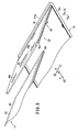
さらに、収容部14と蓋体16とは、ストッパ構造60を介して開放角度が規制されるため、放射線画像読取装置150内に特別の開度規制機構を設ける必要がない。従って、放射線画像読取装置150を経済的に構成することが可能になる。しかも、解除具72a、72bによりスライド部材62a、62bを押圧するだけで、このスライド部材62a、62bが矢印B2方向に移動し、爪状部66a、66bと係止部68a、68bとの係合状態が解除される。このため、蓋体16を、収容部14に対して大きく揺動させることができ、放射線カセッテ10内のメンテナンス等が容易に行われる(図8参照)。   Further, since the opening angle of the housing portion 14 and the lid body 16 is regulated via the stopper structure 60, it is not necessary to provide a special opening degree regulating mechanism in the radiation image reading device 150. Therefore, the radiation image reading apparatus 150 can be configured economically. Moreover, simply by pressing the slide members 62a and 62b with the release tools 72a and 72b, the slide members 62a and 62b move in the direction of the arrow B2, and the claw-like portions 66a and 66b are engaged with the locking portions 68a and 68b. The state is released. For this reason, the cover body 16 can be largely swung with respect to the accommodating part 14, and the maintenance etc. in the radiation cassette 10 are easily performed (refer FIG. 8).

さらにまた、収容部14と蓋体16とは、樹脂ヒンジ18を介して揺動自在に連結されるとともに、互いに嵌合する突起部54a、54b及び溝部56a、56bを有する合わせ構造を採用している。これにより、放射線カセッテ10は、光の進入によるかぶりを防止することができる。   Furthermore, the accommodating portion 14 and the lid body 16 are connected to each other through a resin hinge 18 so as to be swingable, and employ a mating structure having protrusions 54a and 54b and grooves 56a and 56b that fit together. Yes. Thereby, the radiation cassette 10 can prevent the fogging by the entrance of light.

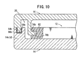
なお、図9に示すように、蓋体16の溝部56aにシール部材98aを配設するとともに、図10に示すように、収容部14の溝部56bにシール部材98bを配設してもよい。このため、放射線カセッテ10は、シール部材98a、98bのシール機能を介して防水性が有効に向上し、例えば、消毒液が前記放射線カセッテ10内に浸入することを防止することが可能になるという利点が得られる。   As shown in FIG. 9, the seal member 98 a may be disposed in the groove portion 56 a of the lid body 16, and the seal member 98 b may be disposed in the groove portion 56 b of the housing portion 14 as illustrated in FIG. 10. For this reason, the radiation cassette 10 is effectively improved in waterproofness through the sealing function of the seal members 98a and 98b, and for example, it becomes possible to prevent the disinfectant from entering the radiation cassette 10. Benefits are gained.

また、少なくとも収容部14、蓋体16又は放射線カセッテ10の他の構成部材のいずれかを、導電性部材で構成しあるいは導電性処理を施して、静電気の発生を阻止することができる。これにより、蓄積性蛍光体プレート12が静電気により悪影響を受けることを防止することが可能になる。   In addition, at least any of the accommodating portion 14, the lid body 16, and the other component members of the radiation cassette 10 may be formed of a conductive member or subjected to a conductive treatment to prevent generation of static electricity. This makes it possible to prevent the stimulable phosphor plate 12 from being adversely affected by static electricity.

さらに、放射線カセッテ10は、抗菌材料で構成され、又は抗菌処理が施されていると、前記放射線カセッテ10の衛生管理が有効に簡素化される。   Furthermore, when the radiation cassette 10 is made of an antibacterial material or is subjected to antibacterial treatment, the hygiene management of the radiation cassette 10 is effectively simplified.

さらにまた、放射線カセッテ10を生分解性樹脂材料で構成することにより、例えば、環境上の問題を惹起することなく耐用年数の過ぎた放射線カセッテ10を廃棄処理することができる。   Furthermore, by configuring the radiation cassette 10 with a biodegradable resin material, for example, the radiation cassette 10 that has passed its useful life can be disposed of without causing environmental problems.

また、蓄積性蛍光体プレート12を保持するガイド構造20は、例えば、図11に示すように、放射線カセッテ10の蓋体16に複数の凸部202a、202bを間欠的に形成し、これらの凸部202a、202bを蓄積性蛍光体プレート12の凹部78a、78bに係合させるように構成することもできる。また、図12に示すように、蓋体16側に形成されるガイド構造を凹部204a、204bによって構成する一方、蓄積性蛍光体プレート12の両側部に凸部206a、206bを形成し、これらの凹部204a、204b及び凸部206a、206bを係合させるように構成することもできる。   Further, the guide structure 20 that holds the stimulable phosphor plate 12 is formed by intermittently forming a plurality of convex portions 202a and 202b on the lid 16 of the radiation cassette 10, as shown in FIG. The portions 202a and 202b may be configured to engage with the recesses 78a and 78b of the stimulable phosphor plate 12. In addition, as shown in FIG. 12, the guide structure formed on the lid 16 side is constituted by the concave portions 204a and 204b, while the convex portions 206a and 206b are formed on both sides of the stimulable phosphor plate 12, The concave portions 204a and 204b and the convex portions 206a and 206b can be configured to engage with each other.

さらにまた、放射線カセッテ10の蓋体16及び蓄積性蛍光体プレート12を図13に示すように構成することにより、蓄積性蛍光体プレート12の誤装填を防止することができる。   Furthermore, by configuring the lid 16 and the stimulable phosphor plate 12 of the radiation cassette 10 as shown in FIG. 13, erroneous loading of the stimulable phosphor plate 12 can be prevented.

すなわち、例えば、蓄積性蛍光体プレート12の端部隅角部に切り欠き部208を形成する一方、蓋体16の樹脂ヒンジ18側の隅角部に切り欠き部208の形状に対応した凸部210を形成する。蓄積性蛍光体プレート12及び蓋体16をこのように構成することにより、蓄積性蛍光体プレート12が正常な状態で装填された場合、切り欠き部208と凸部210とが対応して蓄積性蛍光体プレート12が蓋体16の所定の位置まで装填されるため、装填状態が正常であると判断することができる。一方、蓄積性蛍光体プレート12の前後が逆であったり、表裏が逆であると、切り欠き部208と凸部210との位置が対応しないため、蓄積性蛍光体プレート12の一部が蓋体16から突出し、装填状態が異常であるものと判断することができる。   That is, for example, the notch 208 is formed at the corner of the end of the stimulable phosphor plate 12, while the protrusion corresponding to the shape of the notch 208 is formed at the corner of the lid 16 on the resin hinge 18 side. 210 is formed. By configuring the stimulable phosphor plate 12 and the lid body 16 in this way, when the stimulable phosphor plate 12 is loaded in a normal state, the notch portion 208 and the convex portion 210 correspond to each other and accumulate. Since the phosphor plate 12 is loaded up to a predetermined position of the lid 16, it can be determined that the loaded state is normal. On the other hand, if the front and back of the stimulable phosphor plate 12 are reversed or the front and back are reversed, the positions of the cutout portion 208 and the convex portion 210 do not correspond to each other. It protrudes from the body 16 and it can be determined that the loaded state is abnormal.

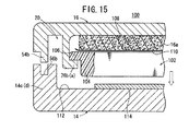
図14は、本発明の他の実施形態に係る放射線カセッテ100が開放された状態の一部断面説明図であり、図15は、前記放射線カセッテ100が閉塞された状態の一部断面説明図である。なお、放射線カセッテ10と同一の構成要素には同一の参照符号を付して、その詳細な説明は省略する。また、以下に説明する実施形態においても、その詳細な説明は省略する。   FIG. 14 is a partial cross-sectional explanatory view in a state where a radiation cassette 100 according to another embodiment of the present invention is opened, and FIG. 15 is a partial cross-sectional explanatory view in a state where the radiation cassette 100 is closed. is there. The same components as those of the radiation cassette 10 are denoted by the same reference numerals, and detailed description thereof is omitted. Also, in the embodiments described below, detailed description thereof is omitted.

放射線カセッテ100には、蓄積性蛍光体プレート(放射線画像記録担体)102が収容される。この蓄積性蛍光体プレート102を構成する枠部材104の両側部には、外方に突出してフランジ部106が形成されており、このフランジ部106は、ガイド構造20を構成する爪部76a、76bに係合可能である。   The radiation cassette 100 accommodates a stimulable phosphor plate (radiation image record carrier) 102. Flange portions 106 are formed on both side portions of the frame member 104 constituting the stimulable phosphor plate 102 so as to protrude outward, and the flange portions 106 are claw portions 76 a and 76 b constituting the guide structure 20. Can be engaged.

蓋体16の内面16aには、スポンジゴム等の弾性体108が固着されるとともに、前記弾性体108に薄板状のプレート110が固定される。このプレート110は、例えば、PPやPET等で構成される。弾性体108は、蓋体16が収容部14を閉塞する際、蓄積性蛍光体プレート102を放射線照射側である前記収容部14の内面112に向かって加圧保持する。   An elastic body 108 such as sponge rubber is fixed to the inner surface 16 a of the lid body 16, and a thin plate-like plate 110 is fixed to the elastic body 108. The plate 110 is made of PP or PET, for example. The elastic body 108 pressurizes and holds the stimulable phosphor plate 102 toward the inner surface 112 of the housing portion 14 on the radiation irradiation side when the lid body 16 closes the housing portion 14.

収容部14の内部には、散乱線除去用グリッド114が配置される。散乱線除去用グリッド114は、Cu(銅)、Pb(鉛)、Ta(タンタル)、Fe(鉄)、W(タングステン)又はWとゴムやプラスチックの複合材で構成される。   A scattered radiation removing grid 114 is disposed inside the accommodating portion 14. The scattered radiation removing grid 114 is made of Cu (copper), Pb (lead), Ta (tantalum), Fe (iron), W (tungsten), or a composite material of W and rubber or plastic.

このように構成される実施形態では、図14に示すように、蓋体16が収容部14に対して所望の開放角度に維持された状態で、蓄積性蛍光体プレート102の着脱作業が行われる。その際、蓄積性蛍光体プレート102の両側部に設けられているフランジ部106は、ガイド構造20を構成する爪部76a、76bに係合し、蓋体16に沿って円滑に移動することができる。   In the embodiment configured as described above, as shown in FIG. 14, the attaching / detaching operation of the stimulable phosphor plate 102 is performed in a state in which the lid body 16 is maintained at a desired opening angle with respect to the housing portion 14. . At that time, the flange portions 106 provided on both sides of the stimulable phosphor plate 102 engage with the claw portions 76 a and 76 b constituting the guide structure 20, and can move smoothly along the lid body 16. it can.

次いで、蓄積性蛍光体プレート102がガイド構造20に支持された状態で、蓋体16が収容部14側に揺動し、この蓋体16が前記収容部14を閉塞して該収容部14に固定される。   Next, in a state where the stimulable phosphor plate 102 is supported by the guide structure 20, the lid body 16 swings toward the housing portion 14, and the lid body 16 closes the housing portion 14 to form the housing portion 14. Fixed.

この場合、蓋体16が収容部14に閉じられると、この蓋体16の内面16aに固着された弾性体108の弾性力を介して、プレート110が蓄積性蛍光体プレート102の裏面(撮影面とは反対の面)を前記収容部14の内面112に向かって押圧する。一方、収容部14の内部には、金属板又は金属複合板からなる散乱線除去用グリッド114が配置されている。   In this case, when the lid body 16 is closed by the accommodating portion 14, the plate 110 is attached to the back surface (photographing surface) of the stimulable phosphor plate 102 through the elastic force of the elastic body 108 fixed to the inner surface 16 a of the lid body 16. The opposite surface) is pressed toward the inner surface 112 of the accommodating portion 14. On the other hand, a scattered radiation removing grid 114 made of a metal plate or a metal composite plate is disposed inside the accommodating portion 14.

これにより、蓄積性蛍光体プレート102は、その撮影面を弾性体108の押圧作用下に散乱線除去用グリッド114に確実に加圧保持され、この蓄積性蛍光体プレート102に対する放射線画像情報の撮影処理が良好に遂行される。従って、高画質の放射線画像情報が確実に得られ、特にリニアック(放射線治療)に好適に採用することができるという効果が得られる。   Thereby, the stimulable phosphor plate 102 is reliably pressed and held by the scattered radiation removing grid 114 under the pressing action of the elastic body 108, and radiographic image information is photographed on the stimulable phosphor plate 102. Processing is performed well. Therefore, high-quality radiographic image information can be obtained with certainty, and an effect that it can be suitably used particularly for linac (radiotherapy) is obtained.

図16は、本発明の他の実施形態に係る放射線カセッテ120の斜視説明図である。   FIG. 16 is a perspective explanatory view of a radiation cassette 120 according to another embodiment of the present invention.

放射線カセッテ120を構成する蓋体16には、平面状の筆記面(筆記部)122が設けられる。この筆記面122は、樹脂プレート材で構成されるとともに、例えば、メラニン系樹脂や含フッ素系樹脂等でコーティングされている。従って、筆記面122は、水性インク等の筆記用具で種々の情報を繰り返し書き消しすることが可能になり、作業性の向上が図られる。   The lid 16 constituting the radiation cassette 120 is provided with a planar writing surface (writing portion) 122. The writing surface 122 is made of a resin plate material and coated with, for example, a melanin resin or a fluorine-containing resin. Therefore, the writing surface 122 can be used to repeatedly erase various information with a writing tool such as water-based ink, thereby improving workability.

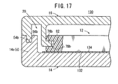
図17は、本発明の他の実施形態に係る放射線カセッテ130の一部断面図である。   FIG. 17 is a partial cross-sectional view of a radiation cassette 130 according to another embodiment of the present invention.

放射線カセッテ130を構成する収容部14内には、この収容部14の内面132に散乱線除去用グリッド134が設けられる。散乱線除去用グリッド134は、例えば、鉛泊で構成されており、内面132に両面テープ等により貼り付けされる。このため、簡単な構成で、画像品質を向上させることができる。   In the accommodating portion 14 constituting the radiation cassette 130, a scattered radiation removing grid 134 is provided on the inner surface 132 of the accommodating portion 14. The scattered radiation removing grid 134 is made of lead, for example, and is affixed to the inner surface 132 with a double-sided tape or the like. Therefore, the image quality can be improved with a simple configuration.

図18は、本発明のさらに他の実施形態に係る放射線カセッテ212の一部断面図である。   FIG. 18 is a partial cross-sectional view of a radiation cassette 212 according to still another embodiment of the present invention.

放射線カセッテ212には、エネルギサブトラクション処理を行うための2枚の蓄積性蛍光体プレート12A及び12Bが装填される。収容部14側に配設される蓄積性蛍光体プレート12Aの枠部材214には、放射線が照射される側にカーボン板216が配設され、そのカーボン板216に両面テープ218を介して蛍光体層220が貼着される。また、蛍光体層220が貼着される枠部材214の反対の面には、両面テープ222を介して、放射線の低エネルギ成分を吸収する放射線エネルギ分離フィルタである銅板224が貼着され、その表面がプラスチックシート226によりカバーされる。蓋体16側に配設される蓄積性蛍光体プレート12Bの枠部材228には、放射線が照射される側にカーボン板230が配設され、そのカーボン板230に両面テープ232を介して蛍光体層234が貼着される。   The radiation cassette 212 is loaded with two stimulable phosphor plates 12A and 12B for performing energy subtraction processing. A carbon plate 216 is disposed on the side irradiated with radiation on the frame member 214 of the stimulable phosphor plate 12A disposed on the accommodating portion 14 side, and the phosphor is disposed on the carbon plate 216 via a double-sided tape 218. Layer 220 is applied. Further, a copper plate 224 that is a radiation energy separation filter that absorbs a low energy component of radiation is attached to the opposite surface of the frame member 214 to which the phosphor layer 220 is attached via a double-sided tape 222, The surface is covered with a plastic sheet 226. The frame member 228 of the stimulable phosphor plate 12B disposed on the lid 16 side is provided with a carbon plate 230 on the side irradiated with radiation, and the phosphor is disposed on the carbon plate 230 via a double-sided tape 232. Layer 234 is applied.

放射線カセッテ212に配設されるガイド構造236は、蓋体16の内面16aに形成される二対の爪部238a、238b及び240a、240bを有する。爪部238a、238b及び240a、240bは、各蓄積性蛍光体プレート12A及び12Bの枠部材214及び228の両側部に形成された凹部242a、242b及び244a、244bに係合する。   The guide structure 236 disposed in the radiation cassette 212 has two pairs of claw portions 238a, 238b and 240a, 240b formed on the inner surface 16a of the lid body 16. The claw portions 238a, 238b and 240a, 240b engage with recesses 242a, 242b and 244a, 244b formed on both sides of the frame members 214 and 228 of the stimulable phosphor plates 12A and 12B.

このように構成される放射線カセッテ212では、収容部14側から被写体を介して照射された放射線により、蓄積性蛍光体プレート12Aの蛍光体層220に放射線画像情報が記録される一方、蓄積性蛍光体プレート12Aの銅板224によって低エネルギ成分が吸収された放射線により、蓄積性蛍光体プレート12Bの蛍光体層234に放射線画像情報が記録される。この放射線カセッテ212は、放射線画像読取装置150に装填され、各蓄積性蛍光体プレート12A及び12Bから放射線画像情報が読み取られた後、エネルギサブトラクション処理によりそれらの差分としての放射線画像情報が得られる。   In the radiation cassette 212 configured as described above, radiation image information is recorded on the phosphor layer 220 of the stimulable phosphor plate 12A by the radiation irradiated from the container 14 side through the subject, while the stimulable fluorescence is recorded. Radiation image information is recorded on the phosphor layer 234 of the stimulable phosphor plate 12B by the radiation in which the low energy component is absorbed by the copper plate 224 of the body plate 12A. The radiation cassette 212 is loaded in the radiation image reading device 150, and after the radiation image information is read from each of the stimulable phosphor plates 12A and 12B, the radiation image information as a difference between them is obtained by energy subtraction processing.

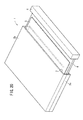
図19は、本発明のさらに他の実施形態に係る放射線カセッテ246の構成図である。この放射線カセッテ246は、蓄積性蛍光体プレート12を収容する収容部248に対して、蓋体250の一部が開閉可能に構成されている。蓄積性蛍光体プレート12を案内するガイド構造252は、収容部248に配設される。すなわち、ガイド構造252を構成する凸部254a、254bは、収容部248の内周面に沿って形成され、これらの凸部254a、254bに対して蓄積性蛍光体プレート12の凹部78a、78bが係合する。   FIG. 19 is a configuration diagram of a radiation cassette 246 according to still another embodiment of the present invention. The radiation cassette 246 is configured such that a part of the lid 250 can be opened and closed with respect to the accommodating portion 248 that accommodates the stimulable phosphor plate 12. A guide structure 252 for guiding the stimulable phosphor plate 12 is disposed in the accommodating portion 248. That is, the convex portions 254a and 254b constituting the guide structure 252 are formed along the inner peripheral surface of the accommodating portion 248, and the concave portions 78a and 78b of the stimulable phosphor plate 12 are formed with respect to the convex portions 254a and 254b. Engage.

蓋体250が開放された後、蓄積性蛍光体プレート12が凸部254a、254bに沿って移動し、収容部248から取り出される。この場合、蓋体250は、その一部だけが収容部248から開放されるため、当該放射線カセッテ246を放射線画像読取装置150に装填した際、大きなスペースを占有することなく、蓋体250を開放させて蓄積性蛍光体プレート12を取り出すことができる。   After the lid 250 is opened, the stimulable phosphor plate 12 moves along the convex portions 254a and 254b and is taken out from the accommodating portion 248. In this case, since only a part of the lid body 250 is opened from the accommodating portion 248, the lid body 250 is opened without occupying a large space when the radiation cassette 246 is loaded in the radiation image reading apparatus 150. Thus, the stimulable phosphor plate 12 can be taken out.

なお、放射線カセッテ246の場合においても、蓄積性蛍光体プレート12側に凸部を形成し、収容部248側に凹部を形成してガイド構造としてもよいことは勿論である。   In the case of the radiation cassette 246 as well, it is of course possible to form a guide structure by forming a convex portion on the stimulable phosphor plate 12 side and forming a concave portion on the accommodating portion 248 side.

本発明の実施形態に係る放射線カセッテの斜視説明図である。It is a perspective explanatory view of a radiation cassette concerning an embodiment of the present invention. 前記放射線カセッテを構成する蓋体ロック手段の斜視説明図である。It is an isometric view explanatory drawing of the cover body locking means which comprises the said radiation cassette. 前記放射線カセッテの図1中、III−III線断面図である。It is the III-III sectional view taken on the line in FIG. 1 of the said radiation cassette. 前記放射線カセッテの図1中、IV−IV線断面図である。It is the IV-IV sectional view taken on the line in FIG. 1 of the said radiation cassette. 前記放射線カセッテを構成するストッパ構造の要部斜視説明図である。It is principal part perspective explanatory drawing of the stopper structure which comprises the said radiation cassette. 蓄積性蛍光体プレートの一部断面説明図である。It is a partial cross section explanatory drawing of a stimulable phosphor plate. 放射線カセッテに装填された蓄積性蛍光体プレートから放射線画像情報を読み取る放射線画像読取装置の構成図である。It is a block diagram of the radiographic image reading apparatus which reads radiographic image information from the stimulable fluorescent substance plate with which the radiographic cassette was loaded. 前記ストッパ構造が解除された状態の斜視説明図である。It is a perspective explanatory view in the state where the stopper structure was released. 蓋体の溝部にシール部材が配設された際の一部断面図である。It is a partial cross section figure at the time of the seal member being arrange | positioned in the groove part of a cover body. 収容部の溝部にシール部材が配設された際の一部断面図である。It is a partial cross section figure at the time of the seal member being arrange | positioned in the groove part of an accommodating part. 他の実施形態のガイド構造の斜視説明図である。It is a perspective explanatory view of the guide structure of other embodiments. 他の実施形態のガイド構造の斜視説明図である。It is a perspective explanatory view of the guide structure of other embodiments. 蓄積性蛍光体プレートの誤装填を防止する機構の斜視説明図である。It is a perspective explanatory view of a mechanism for preventing erroneous loading of the stimulable phosphor plate. 本発明の他の実施形態に係る放射線カセッテが開放された状態の一部断面説明図である。It is a partial cross section explanatory view of the state where the radiation cassette concerning other embodiments of the present invention was opened. 前記放射線カセッテが閉塞された状態の一部断面説明図である。It is a partial cross section explanatory view of the state where the radiation cassette was obstructed. 本発明の他の実施形態に係る放射線カセッテの斜視説明図である。It is a perspective explanatory view of a radiation cassette concerning other embodiments of the present invention. 本発明の他の実施形態に係る放射線カセッテの一部断面図である。It is a partial cross section figure of the radiation cassette concerning other embodiments of the present invention. 本発明の他の実施形態に係る放射線カセッテの一部断面図である。It is a partial cross section figure of the radiation cassette concerning other embodiments of the present invention. 本発明の他の実施形態に係る放射線カセッテの構成斜視図である。It is a composition perspective view of a radiation cassette concerning other embodiments of the present invention. 特許文献1のカセッテの説明図である。It is explanatory drawing of the cassette of patent document 1. FIG.

符号の説明Explanation of symbols

10、100、120、130、212、246…放射線カセッテ
12、12A、12B、102…蓄積性蛍光体プレート
14、248…収容部 16、250…蓋体
16a、112…内面 18…樹脂ヒンジ
20…ガイド構造 22…開口部
24…蓋体ロック手段 54a、54b…突起部
56a、56b…溝部 60…ストッパ構造
62a、62b…スライド部材 66a、66b…爪状部
68a、68b…係止部 76a、76b…爪部
78a、78b、204a、204b…凹部 80…蛍光体層
82、104、214、228…枠部材 98a、98b…シール部材
106…フランジ部 108…弾性体
110…プレート
114、134…散乱線除去用グリッド 122…筆記面
150…放射線画像読取装置

10, 100, 120, 130, 212, 246... Radiation cassettes 12, 12A, 12B, 102... Stimulable phosphor plates 14, 248... Housing 16, 250. Guide structure 22 ... Opening 24 ... Lid locking means 54a, 54b ... Protrusion 56a, 56b ... Groove 60 ... Stopper structure 62a, 62b ... Slide member 66a, 66b ... Claw-like part 68a, 68b ... Locking part 76a, 76b ... claw portions 78a, 78b, 204a, 204b ... concave portion 80 ... phosphor layers 82, 104, 214, 228 ... frame members 98a, 98b ... seal members 106 ... flange portions 108 ... elastic bodies 110 ... plates 114, 134 ... scattered rays Removal grid 122 ... writing surface 150 ... radiation image reading apparatus

Claims (13)

被写体の放射線画像情報が記録されるプレート状の放射線画像記録担体を収容する放射線カセッテであって、
前記放射線画像記録担体を収容する収容部と、
前記放射線画像記録担体の取り出し又は挿入を行うべく、前記収容部に開閉自在に装着される蓋体と、
を備え、
前記蓋体又は前記収容部には、前記蓋体が前記収容部に対して開放された状態で、前記放射線画像記録担体の取り出し又は挿入を行う際に、前記放射線画像記録担体を案内するガイド構造が設けられることを特徴とする放射線カセッテ。
A radiation cassette containing a plate-shaped radiation image record carrier on which radiation image information of a subject is recorded,
An accommodating portion for accommodating the radiographic image record carrier;
A lid that can be freely opened and closed in the housing portion in order to take out or insert the radiation image record carrier;
With
A guide structure for guiding the radiographic image record carrier when the radiographic image record carrier is taken out or inserted in the state where the lid is opened with respect to the accommodating portion. Radiation cassette characterized by being provided with.
請求項1記載の放射線カセッテにおいて、前記ガイド構造は、前記放射線画像記録担体の取り出し又は挿入方向に延在し且つ互いに対向する一対の係合部を備え、
前記係合部には、前記放射線画像記録担体の両側部がスライド自在に係合することを特徴とする放射線カセッテ。
2. The radiation cassette according to claim 1, wherein the guide structure includes a pair of engaging portions extending in a direction of taking out or inserting the radiation image record carrier and facing each other.
The radiation cassette is characterized in that both sides of the radiographic image record carrier are slidably engaged with the engaging portion.
請求項2記載の放射線カセッテにおいて、前記係合部と、前記係合部に係合する前記放射線画像記録担体の両側部とは、一方が凸形状かならり、他方が凹形状からなることを特徴とする放射線カセッテ。   3. The radiation cassette according to claim 2, wherein one of the engaging portion and both side portions of the radiographic image recording carrier engaged with the engaging portion has a convex shape and the other has a concave shape. Characteristic radiation cassette. 請求項1記載の放射線カセッテにおいて、前記収容部と前記蓋体との間には、該蓋体の開放角度を規制するとともに、該規制を解除可能なストッパ構造が設けられることを特徴とする放射線カセッテ。   The radiation cassette according to claim 1, wherein a stopper structure that restricts an opening angle of the lid and releases the regulation is provided between the housing portion and the lid. Cassette. 請求項1記載の放射線カセッテにおいて、前記収容部と前記蓋体とは、ヒンジで連結されるとともに、
前記収容部と前記蓋体とは、互いに嵌合する溝部及び突起部を有する合わせ構造により閉塞可能であることを特徴とする放射線カセッテ。
The radiation cassette according to claim 1, wherein the accommodating portion and the lid are connected by a hinge,
2. The radiation cassette according to claim 1, wherein the housing portion and the lid body can be closed by a mating structure having a groove portion and a protrusion portion that are fitted to each other.
請求項5記載の放射線カセッテにおいて、前記合わせ構造には、シール部材が取り付けられることを特徴とする放射線カセッテ。   6. The radiation cassette according to claim 5, wherein a sealing member is attached to the mating structure. 請求項1記載の放射線カセッテにおいて、前記蓋体の内面に配置される弾性体を備え、
前記蓋体が前記収容部を閉塞する際、前記弾性体が前記放射線画像記録担体を放射線照射側である前記収容部の内面に向かって加圧保持することを特徴とする放射線カセッテ。
The radiation cassette according to claim 1, further comprising an elastic body disposed on an inner surface of the lid body,
The radiation cassette is characterized in that, when the lid closes the housing portion, the elastic body pressurizes and holds the radiation image recording carrier toward the inner surface of the housing portion on the radiation irradiation side.
請求項1記載の放射線カセッテにおいて、前記収容部の内部には、金属板又は金属複合板からなる散乱線除去用グリッドが配置されることを特徴とする放射線カセッテ。   The radiation cassette according to claim 1, wherein a scattered radiation removing grid made of a metal plate or a metal composite plate is disposed inside the housing portion. 請求項1記載の放射線カセッテにおいて、少なくとも前記蓋体、前記収容部又は他のカセッテ構成部材のいずれかは、導電性を有することを特徴とする放射線カセッテ。   2. The radiation cassette according to claim 1, wherein at least one of the lid, the accommodating portion, and the other cassette constituent member has conductivity. 請求項1記載の放射線カセッテにおいて、前記放射線カセッテは、抗菌材料で構成され、又は抗菌処理が施されていることを特徴とする放射線カセッテ。   The radiation cassette according to claim 1, wherein the radiation cassette is made of an antibacterial material or is subjected to an antibacterial treatment. 請求項1記載の放射線カセッテにおいて、前記放射線カセッテは、生分解性樹脂材料で構成されることを特徴とする放射線カセッテ。   The radiation cassette according to claim 1, wherein the radiation cassette is made of a biodegradable resin material. 請求項1記載の放射線カセッテにおいて、前記蓋体には、筆記用具で繰り返し書き消し可能な筆記部が設けられることを特徴とする放射線カセッテ。   The radiation cassette according to claim 1, wherein the lid is provided with a writing portion that can be repeatedly erased with a writing instrument. 請求項1記載の放射線カセッテにおいて、前記収容部は、エネルギサブトラクション処理を行うための2枚の前記放射線画像記録担体を重畳させて収容し、前記ガイド構造は、前記各放射線画像記録担体を取り出し又は挿入すべく案内することを特徴とする放射線カセッテ。

2. The radiation cassette according to claim 1, wherein the accommodating portion accommodates two of the radiation image record carriers for performing energy subtraction processing in an overlapping manner, and the guide structure takes out each of the radiation image record carriers or A radiation cassette characterized by being guided to be inserted.

JP2004112006A 2003-09-05 2004-04-06 Radiation cassette Pending JP2005258370A (en)

Priority Applications (2)

Application Number Priority Date Filing Date Title
JP2004112006A JP2005258370A (en) 2003-09-05 2004-04-06 Radiation cassette
US10/933,362 US7556426B2 (en) 2003-09-05 2004-09-03 Radiation cassette

Applications Claiming Priority (3)

Application Number Priority Date Filing Date Title
JP2003314226 2003-09-05
JP2004036718 2004-02-13
JP2004112006A JP2005258370A (en) 2003-09-05 2004-04-06 Radiation cassette

Publications (2)

Publication Number Publication Date
JP2005258370A true JP2005258370A (en) 2005-09-22
JP2005258370A5 JP2005258370A5 (en) 2007-03-29

Family

ID=34229127

Family Applications (1)

Application Number Title Priority Date Filing Date
JP2004112006A Pending JP2005258370A (en) 2003-09-05 2004-04-06 Radiation cassette

Country Status (2)

Country Link
US (1) US7556426B2 (en)
JP (1) JP2005258370A (en)

Cited By (1)

* Cited by examiner, † Cited by third party
Publication number Priority date Publication date Assignee Title
JP2011112921A (en) * 2009-11-27 2011-06-09 Canon Inc Storage device

Families Citing this family (14)

* Cited by examiner, † Cited by third party
Publication number Priority date Publication date Assignee Title
DE102005046314A1 (en) * 2005-09-27 2007-03-29 Dürr Dental GmbH & Co. KG Storage film positioning device for e.g. in field of human medicine, has set of spaced apart guiding units on rear side of storage film, where guiding units interact with guide rails that are provided in cartridge
MX2010004542A (en) * 2007-10-29 2010-08-31 Tigenix Ltd Implant delivery device and method.
US7924974B2 (en) * 2008-09-29 2011-04-12 Mir Medical Imaging Research Holding Gmbh X-ray machine for breast examination in a standing position
DE102008052985A1 (en) * 2008-10-23 2010-04-29 Li-Tec Battery Gmbh Packaging device and packaging system for substantially flat objects, for example lithium-ion cells
US7896546B2 (en) * 2009-05-12 2011-03-01 Reina Imaging X-Ray Cassette Co., Inc. Method of incorporating an X-ray grid into a CR cassette
US8558207B2 (en) * 2009-09-29 2013-10-15 Carestream Health, Inc. Photostimulable plate reading device
CN104039228B (en) 2011-11-15 2017-06-30 未来解决方案有限公司 Devices, systems and methods for producing radioscopic image
US8939289B2 (en) * 2012-12-14 2015-01-27 Shenzhen China Star Optoelectronics Technology Co., Ltd Packing box for liquid crystal display panel and waterproof structure thereof
JP6043737B2 (en) * 2013-01-30 2016-12-14 富士フイルム株式会社 Radiography equipment
JP2015099400A (en) * 2015-02-23 2015-05-28 富士フイルム株式会社 Imaging plate unit and application of the same
FR3038739B1 (en) * 2015-07-08 2018-03-02 Trixell PORTABLE RADIOLOGICAL CASSETTE WITH PATIENT IDENTIFICATION MEANS
DE102016117051A1 (en) * 2016-09-12 2018-03-15 DüRR DENTAL AG System and method for providing acquisition parameters
US10444378B1 (en) * 2018-04-27 2019-10-15 Varian Medical Systems, Inc. Imaging devices
US11016202B2 (en) 2018-04-26 2021-05-25 Varian Medical Systems, Inc. Imaging devices

Citations (1)

* Cited by examiner, † Cited by third party
Publication number Priority date Publication date Assignee Title
JP2002311527A (en) * 2001-04-11 2002-10-23 Canon Inc X-ray image photographing device

Family Cites Families (10)

* Cited by examiner, † Cited by third party
Publication number Priority date Publication date Assignee Title
JPS5639533A (en) * 1979-09-06 1981-04-15 Toshiba Corp Photographic plateholder for x-ray
US5101423A (en) * 1989-02-15 1992-03-31 Kabushiki Kaisha Okamoto Seisakusho X-ray cassette
JP2727272B2 (en) 1992-03-31 1998-03-11 富士写真フイルム株式会社 Cassette
JPH11271894A (en) 1998-03-20 1999-10-08 Konica Corp Cassette for radiation image reader/recorder and radiation image recorder/reader
JP3980233B2 (en) 1998-12-28 2007-09-26 富士フイルム株式会社 Radiation image conversion panel and manufacturing method thereof
US6557705B1 (en) * 1999-08-31 2003-05-06 Fuji Photo Film Co., Ltd. Radiation cassette
JP4221144B2 (en) * 2000-12-28 2009-02-12 富士フイルム株式会社 Radiation cassette
JP3870738B2 (en) 2001-10-02 2007-01-24 コニカミノルタホールディングス株式会社 Radiography cassette
JP2003199734A (en) 2002-01-07 2003-07-15 Konica Corp Radiographic cassette
JP4000587B2 (en) 2002-01-10 2007-10-31 コニカミノルタホールディングス株式会社 Radiation imaging cassette and mammography cassette

Patent Citations (1)

* Cited by examiner, † Cited by third party
Publication number Priority date Publication date Assignee Title
JP2002311527A (en) * 2001-04-11 2002-10-23 Canon Inc X-ray image photographing device

Cited By (2)

* Cited by examiner, † Cited by third party
Publication number Priority date Publication date Assignee Title
JP2011112921A (en) * 2009-11-27 2011-06-09 Canon Inc Storage device
US8916844B2 (en) 2009-11-27 2014-12-23 Canon Kabushiki Kaisha Container apparatus

Also Published As

Publication number Publication date
US20050051447A1 (en) 2005-03-10
US7556426B2 (en) 2009-07-07

Similar Documents

Publication Publication Date Title
JP2005258370A (en) Radiation cassette
JP4241402B2 (en) Cassette for radiation imaging equipment
JP4000587B2 (en) Radiation imaging cassette and mammography cassette
US6669363B2 (en) Radiation cassette
US6557705B1 (en) Radiation cassette
US7242011B2 (en) Radiation image forming unit and cassette
JP2004279408A (en) Radiation image forming unit and its cassette
JP4512547B2 (en) Radiation cassette
JP2005275011A (en) Cassette
JP2004264547A (en) Radiation cassette holder
JP3919392B2 (en) Radiation cassette
WO2012125244A2 (en) Computed radiography scanner and envelope for imaging plates
JP2005275012A (en) Cassette
JP5615866B2 (en) Cassette
JP4504597B2 (en) Radiographic image reading method of accumulative phosphor sheet using radiation cassette
JPH05281636A (en) Cassette
JP2005084242A (en) Destaticization structure of radiation cassette
EP1089120B1 (en) Radiation cassette
JP2001350231A (en) Radiation cassette
JP4028161B2 (en) Radiation cassette
EP1089121B1 (en) Radiation cassette
JP2004279575A (en) Connecting structure for radiation cassette
JP2003287833A (en) Cassette for photographing radiation image and radiographic image reader
JP2588271B2 (en) Automatic insertion mechanism for stimulable phosphor sheet
JP2002250980A (en) Radiation cassette

Legal Events

Date Code Title Description
A711 Notification of change in applicant

Free format text: JAPANESE INTERMEDIATE CODE: A712

Effective date: 20061211

A521 Written amendment

Free format text: JAPANESE INTERMEDIATE CODE: A523

Effective date: 20070209

A621 Written request for application examination

Free format text: JAPANESE INTERMEDIATE CODE: A621

Effective date: 20070209

A977 Report on retrieval

Free format text: JAPANESE INTERMEDIATE CODE: A971007

Effective date: 20091112

A131 Notification of reasons for refusal

Free format text: JAPANESE INTERMEDIATE CODE: A131

Effective date: 20091117

A02 Decision of refusal

Free format text: JAPANESE INTERMEDIATE CODE: A02

Effective date: 20100323