WO2011055431A1 - Apparatus for controlling internal combustion engine - Google Patents
Apparatus for controlling internal combustion engine Download PDFInfo
- Publication number
- WO2011055431A1 WO2011055431A1 PCT/JP2009/068841 JP2009068841W WO2011055431A1 WO 2011055431 A1 WO2011055431 A1 WO 2011055431A1 JP 2009068841 W JP2009068841 W JP 2009068841W WO 2011055431 A1 WO2011055431 A1 WO 2011055431A1
- Authority
- WO
- WIPO (PCT)
- Prior art keywords
- amount
- valve
- pipe pressure
- blow
- intake
- Prior art date
Links
Images


Classifications
-
- F—MECHANICAL ENGINEERING; LIGHTING; HEATING; WEAPONS; BLASTING
- F02—COMBUSTION ENGINES; HOT-GAS OR COMBUSTION-PRODUCT ENGINE PLANTS
- F02D—CONTROLLING COMBUSTION ENGINES
- F02D23/00—Controlling engines characterised by their being supercharged
-
- F—MECHANICAL ENGINEERING; LIGHTING; HEATING; WEAPONS; BLASTING
- F02—COMBUSTION ENGINES; HOT-GAS OR COMBUSTION-PRODUCT ENGINE PLANTS
- F02D—CONTROLLING COMBUSTION ENGINES
- F02D41/00—Electrical control of supply of combustible mixture or its constituents
- F02D41/0002—Controlling intake air
- F02D41/0007—Controlling intake air for control of turbo-charged or super-charged engines
-
- F—MECHANICAL ENGINEERING; LIGHTING; HEATING; WEAPONS; BLASTING
- F02—COMBUSTION ENGINES; HOT-GAS OR COMBUSTION-PRODUCT ENGINE PLANTS
- F02D—CONTROLLING COMBUSTION ENGINES
- F02D41/00—Electrical control of supply of combustible mixture or its constituents
- F02D41/30—Controlling fuel injection
- F02D41/38—Controlling fuel injection of the high pressure type
- F02D41/40—Controlling fuel injection of the high pressure type with means for controlling injection timing or duration
- F02D41/401—Controlling injection timing
-
- F—MECHANICAL ENGINEERING; LIGHTING; HEATING; WEAPONS; BLASTING
- F02—COMBUSTION ENGINES; HOT-GAS OR COMBUSTION-PRODUCT ENGINE PLANTS
- F02D—CONTROLLING COMBUSTION ENGINES
- F02D41/00—Electrical control of supply of combustible mixture or its constituents
- F02D41/0002—Controlling intake air
- F02D2041/001—Controlling intake air for engines with variable valve actuation
-
- F—MECHANICAL ENGINEERING; LIGHTING; HEATING; WEAPONS; BLASTING
- F02—COMBUSTION ENGINES; HOT-GAS OR COMBUSTION-PRODUCT ENGINE PLANTS
- F02D—CONTROLLING COMBUSTION ENGINES
- F02D41/00—Electrical control of supply of combustible mixture or its constituents
- F02D41/30—Controlling fuel injection
- F02D41/38—Controlling fuel injection of the high pressure type
- F02D2041/389—Controlling fuel injection of the high pressure type for injecting directly into the cylinder
-
- F—MECHANICAL ENGINEERING; LIGHTING; HEATING; WEAPONS; BLASTING
- F02—COMBUSTION ENGINES; HOT-GAS OR COMBUSTION-PRODUCT ENGINE PLANTS
- F02D—CONTROLLING COMBUSTION ENGINES
- F02D2200/00—Input parameters for engine control
- F02D2200/02—Input parameters for engine control the parameters being related to the engine
- F02D2200/04—Engine intake system parameters
- F02D2200/0406—Intake manifold pressure
- F02D2200/0408—Estimation of intake manifold pressure
-
- Y—GENERAL TAGGING OF NEW TECHNOLOGICAL DEVELOPMENTS; GENERAL TAGGING OF CROSS-SECTIONAL TECHNOLOGIES SPANNING OVER SEVERAL SECTIONS OF THE IPC; TECHNICAL SUBJECTS COVERED BY FORMER USPC CROSS-REFERENCE ART COLLECTIONS [XRACs] AND DIGESTS
- Y02—TECHNOLOGIES OR APPLICATIONS FOR MITIGATION OR ADAPTATION AGAINST CLIMATE CHANGE
- Y02T—CLIMATE CHANGE MITIGATION TECHNOLOGIES RELATED TO TRANSPORTATION
- Y02T10/00—Road transport of goods or passengers
- Y02T10/10—Internal combustion engine [ICE] based vehicles
- Y02T10/12—Improving ICE efficiencies
-
- Y—GENERAL TAGGING OF NEW TECHNOLOGICAL DEVELOPMENTS; GENERAL TAGGING OF CROSS-SECTIONAL TECHNOLOGIES SPANNING OVER SEVERAL SECTIONS OF THE IPC; TECHNICAL SUBJECTS COVERED BY FORMER USPC CROSS-REFERENCE ART COLLECTIONS [XRACs] AND DIGESTS
- Y02—TECHNOLOGIES OR APPLICATIONS FOR MITIGATION OR ADAPTATION AGAINST CLIMATE CHANGE
- Y02T—CLIMATE CHANGE MITIGATION TECHNOLOGIES RELATED TO TRANSPORTATION
- Y02T10/00—Road transport of goods or passengers
- Y02T10/10—Internal combustion engine [ICE] based vehicles
- Y02T10/40—Engine management systems
Definitions
- the present invention relates to a control device for an internal combustion engine.
- the intake pressure may be higher than the exhaust pressure. Therefore, when the intake valve and the exhaust valve are both open, the fresh air that has flowed into the combustion chamber is exhausted. May blow through to the exhaust side.
- the content of appropriate engine control for improving the fuel consumption and emission of the internal combustion engine with a supercharger varies depending on whether or not fresh air is blown out. Therefore, in order to perform optimal engine control, it is desired to accurately detect the presence or absence of fresh air.
- Japanese Patent Application Laid-Open No. 2008-75549 calculates the internal EGR scavenging amount based on the intake pressure, exhaust pressure, engine speed, and control state of the variable valve mechanism of the intake valve, and blows out based on the internal EGR scavenging amount.
- An apparatus is disclosed that controls to reduce the valve overlap period when it is determined whether or not there is a blow-through.
- the amount of intake air blown to the exhaust side is experimentally obtained in advance and stored in the control unit in the form of a map as a function of engine speed and engine load.
- an apparatus for calculating the amount of intake air that blows through to the exhaust side is disclosed.
- the fuel injection amount is calculated based on a value obtained by subtracting the amount of intake air that blows to the exhaust side from the intake air amount detected by the air flow meter. I have to.
- valve timing is a function of the engine speed and the engine load. Assuming that it becomes a function, the blow-by amount is stored as a map for engine speed and engine load.
- the valve timing is not necessarily a function of the engine speed and the engine load. That is, the engine may operate at a valve timing different from a preset valve timing in a transient operation state or when there is a request from another control. For this reason, the above conventional technique cannot accurately determine the presence or absence of a blow-through.
- the present invention has been made to solve the above-described problems, and controls an internal combustion engine that can accurately determine whether or not fresh air is blown into an exhaust passage in an internal combustion engine equipped with a supercharger.
- An object is to provide an apparatus.
- a first invention is a control device for an internal combustion engine, A supercharger having a compressor for compressing air in the intake passage; Intake pipe pressure acquisition means for detecting or estimating the intake pipe pressure; An intake variable valve operating device that makes the valve timing of the intake valve variable; An exhaust variable valve operating device that makes the valve timing of the exhaust valve variable; Storage means for storing information related to a reference intake pipe pressure, which is a value that depends on the valve timing of the intake valve and that does not depend on the valve timing of the exhaust valve; Reference intake pipe pressure acquisition means for acquiring a reference intake pipe pressure corresponding to the valve timing of the intake valve based on information stored in the storage means; Based on the result of comparison between the intake pipe pressure detected or estimated by the intake pipe pressure acquisition means and the reference intake pipe pressure acquired by the reference intake pipe pressure acquisition means, the flow of fresh air to the exhaust side is reduced.
- Blow-through determination means for determining presence or absence; It is characterized by providing.
- the second invention is the first invention, wherein A blow-off amount calculating means for calculating the amount of fresh air blown to the exhaust side based on the intake pipe pressure detected or estimated by the intake pipe pressure acquiring means when the blow-through determining means determines that there is a blow-through. It is characterized by providing.
- the third invention is the first or second invention, wherein
- the reference intake pipe pressure includes a region in which the amount of fresh air flowing from the intake valve decreases when the valve timing of the exhaust valve is retarded while the valve timing of the intake valve is constant, and the valve timing of the intake valve Is a boundary value with a region where the amount of fresh air flowing from the intake valve increases when the valve timing of the exhaust valve is retarded.
- a fuel injection device In-cylinder freshness that calculates the amount of fresh air to be filled in the cylinder based on the intake pipe pressure detected or estimated by the intake pipe pressure acquisition means when the blow-by determination means determines that there is a blow-through.
- a volume calculation means First fuel injection amount calculating means for calculating a fuel injection amount based on the in-cylinder fresh air amount calculated by the in-cylinder fresh air amount calculating means and a target air-fuel ratio;
- Injection control means for causing the fuel injection device to inject the amount of fuel calculated by the first fuel injection amount calculating means after the exhaust valve is closed when the blow-by determining means determines that there is a blow-through.
- the fifth invention is the fourth invention, wherein
- the fuel injection device includes an in-cylinder fuel injection device that directly injects fuel into a cylinder,
- the injection control means causes the in-cylinder fuel injection device to inject the amount of fuel calculated by the first fuel injection amount calculation means when the blow-by determination means determines that there is a blow-through.
- the sixth invention is the fourth or fifth invention, wherein Fresh air inflow amount calculating means for calculating the amount of fresh air flowing from the intake valve; Second fuel injection amount calculating means for calculating a fuel injection amount based on the fresh air inflow amount calculated by the fresh air inflow amount calculating means and a target air-fuel ratio; With The injection control means causes the fuel injection device to inject the amount of fuel calculated by the second fuel injection amount calculation means when it is determined by the blow-by determination means that there is no blow-through. To do.
- the seventh invention is the sixth invention, wherein Rich spike control means for performing rich spike control to temporarily enrich the air-fuel ratio of exhaust gas when necessary,
- Rich spike control means for performing rich spike control to temporarily enrich the air-fuel ratio of exhaust gas when necessary
- the injection control means has the amount of fuel calculated by the second fuel injection amount calculation means regardless of the determination result of the blow-by determination means. Is injected into the fuel injection device.
- an eighth invention is any one of the first to seventh inventions,
- the supercharger drives the compressor with a turbine that is operated by a flow of exhaust gas.
- a compressor model including a time constant relating to a delay in the change in the rotational speed of the turbocharger with respect to a change in the intake air flow rate in a transient operation state, and a map representing a relationship between the intake air flow rate and the supercharging pressure in a steady operation state
- a compressor flow rate estimating means for estimating a flow rate of fresh air passing through the compressor;
- the compressor flow rate estimating means includes compressor model correcting means for correcting at least one of the time constant and the map based on a parameter affecting the magnitude of exhaust energy.
- the ninth invention is the eighth invention, wherein A blow-off amount calculating means for calculating the amount of fresh air blown to the exhaust side based on the intake pipe pressure detected or estimated by the intake pipe pressure acquiring means when the blow-through determining means determines that there is a blow-through.
- the compressor model correcting means includes means for correcting the time constant and the map using the blow-through amount calculated by the blow-through amount calculating means as the parameter.
- the tenth aspect of the invention is the eighth aspect of the invention, Exhaust gas recirculation means for enabling exhaust gas recirculation; An exhaust gas recirculation amount acquisition means for acquiring an exhaust gas recirculation amount; With The compressor model correction means includes means for correcting the time constant and the map using the exhaust gas recirculation amount acquired by the exhaust gas recirculation amount acquisition means as the parameter.
- the eleventh aspect of the invention is the eighth aspect of the invention.
- the compressor model correcting means includes means for correcting the time constant and the map using the valve timing of the exhaust valve as the parameter.
- the twelfth invention is the eighth invention, wherein When the actual ignition timing is retarded with respect to the normal ignition timing, the ignition timing retardation amount obtaining means for obtaining the ignition timing retardation amount is provided,
- the compressor model correcting means includes means for correcting the time constant using the ignition timing retardation amount as the parameter.
- the intake pipe pressure is detected or estimated, and whether or not fresh air has blown into the exhaust side is accurately determined based on the result of comparing the intake pipe pressure with the reference intake pipe pressure.
- the reference intake pipe pressure depends on the valve timing of the intake valve, but is not dependent on the valve timing of the exhaust valve. For this reason, even in an internal combustion engine equipped with an exhaust variable valve operating device, it is easy to test and inspect the reference intake pipe pressure in advance, so that the number of adaptation steps at the development stage can be reduced.
- the amount of fresh air that blows through to the exhaust side can be calculated. Therefore, when the blow-through of fresh air into the exhaust side occurs, control that corrects the fuel injection amount and the like more appropriately. Can be executed.
- the amount of fresh air flowing from the intake valve decreases, and the intake valve Whether or not fresh air is blown out to the exhaust side by setting the boundary value with the region where the amount of fresh air flowing in from the intake valve increases when the valve timing of the exhaust valve is retarded while the valve timing of the exhaust valve is retarded Can be determined with high accuracy.
- unburned fuel can be prevented from being included in the fresh air blown to the exhaust side. That is, fuel that flows unnecessarily to the exhaust side without being burned can be surely eliminated, so that fuel consumption can be improved. Further, even when fresh air is blown through to the exhaust side, the air-fuel ratio in the cylinder can be accurately matched with the target air-fuel ratio.
- the fuel when it is determined that there is a fresh air blow-out to the exhaust side, the fuel can be injected into the cylinder. Thereby, it can prevent more reliably that unburned fuel is contained in the fresh air which blows through to the exhaust side.
- the fuel injection amount is calculated based on the amount of fresh air flowing from the intake valve and the target air-fuel ratio. To do. Thereby, the air-fuel ratio in the cylinder can be matched with the target air-fuel ratio.
- the amount of fuel calculated based on the amount of fresh air flowing in from the intake valve and the target air-fuel ratio, regardless of whether there is a blow-through or not. Can be injected.
- the air-fuel ratio of the exhaust gas can be accurately matched with the target rich air-fuel ratio regardless of whether there is a blow-through, and thus an excellent exhaust gas purification rate can be obtained.
- the influence of the fresh air blow-out to the exhaust side can be appropriately reflected in the compressor model, so that the estimation accuracy of the compressor flow rate can be improved.
- the effect of exhaust gas recirculation can be appropriately reflected in the compressor model, so that the estimation accuracy of the compressor flow rate can be improved.
- the influence of the valve timing of the exhaust valve can be appropriately reflected in the compressor model, so that the estimation accuracy of the compressor flow rate can be improved.
- the influence of the ignition timing retardation control can be appropriately reflected in the compressor model, so that the estimation accuracy of the compressor flow rate can be improved.
- Embodiment 1 of this invention is a graph showing a Pm-Mc relationship when the intake valve timing InVT is fixed and the exhaust valve timing ExVT is varied.
- FIG. 1 is a diagram for explaining a system configuration according to the first embodiment of the present invention.
- the system according to the first embodiment of the present invention includes an internal combustion engine 10.
- the internal combustion engine 10 of the present embodiment is a spark ignition type and capable of lean burn operation.
- the number of cylinders and the cylinder arrangement of the internal combustion engine 10 are not particularly limited. In FIG. 1, only one cylinder is representatively depicted.
- Each cylinder of the internal combustion engine 10 is provided with a piston 12, an intake valve 14, an exhaust valve 16, a spark plug 18, and an in-cylinder injector 20 that directly injects fuel into the cylinder (combustion chamber). Yes.
- the intake valve 14 communicates with the intake passage 22 (surge tank 36) via an intake pipe 38.
- the exhaust valve 16 communicates with the exhaust passage 24 via the exhaust pipe 40.
- the internal combustion engine 10 of the present embodiment is provided with a turbocharger 26, an intake variable valve operating device 44, and an exhaust variable valve operating device 46.
- the turbocharger 26 has a compressor 26a and a turbine 26b.
- the turbine 26 b is disposed in the middle of the exhaust passage 24 and rotates by the energy of the exhaust gas flowing through the exhaust passage 24.
- the compressor 26 a is disposed in the middle of the intake passage 22, and is compressed by the air in the intake passage 22 by being driven by the turbine 26 b and rotating.
- the rotational speed of the turbocharger 26 is referred to as “turbo rotational speed”.
- an air cleaner 28 and an air flow meter 30 for detecting the intake air amount are installed in the intake passage 22 upstream of the compressor 26a.
- An intercooler 32, a throttle valve 34, and a surge tank 36 are provided in the intake passage 22 downstream of the compressor 26a.
- a NOx occlusion reduction type three-way catalyst 42 is installed in the exhaust passage 24 downstream of the turbine 26b.
- the NOx storage reduction type three-way catalyst 42 stores NOx when the air-fuel ratio of the inflowing exhaust gas is lean, and reduces and purifies the stored NOx to N 2 when the air-fuel ratio of the inflowing exhaust gas is rich. Can be released.
- the intake variable valve operating device 44 is a device that can change the valve timing (hereinafter referred to as “intake valve timing”) InVT of the intake valve 14.
- intake valve timing valve timing
- a mechanism is used in which the rotation phase of the camshaft that drives the intake valve 14 relative to the rotation phase of the crankshaft (not shown) of the internal combustion engine 10 is changed by an actuator. Can do.
- the rotation angle of the camshaft that drives the intake valve 14 is detected by a cam position sensor 48. Based on the signal of the cam position sensor 48, the actual (current) intake valve timing InVT can be detected.
- the exhaust variable valve operating device 46 is a device that can change the valve timing (hereinafter referred to as “exhaust valve timing”) ExVT of the exhaust valve 16.
- exhaust valve timing valve timing
- a mechanism is used in which the rotational phase of the camshaft that drives the exhaust valve 16 relative to the rotational phase of the crankshaft (not shown) of the internal combustion engine 10 is changed by an actuator. Can do.
- a cam position sensor 50 detects the rotation angle of the camshaft that drives the exhaust valve 16. Based on the signal from the cam position sensor 50, the actual (current) exhaust valve timing ExVT can be detected.
- the configuration of the intake variable valve operating device 44 or the exhaust variable valve operating device 46 is not limited to the above configuration. That is, the intake variable valve operating device 44 or the exhaust variable valve operating device 46 may be, for example, a mechanism that can change the operating angle of the intake valve 14 or the exhaust valve 16, or the intake valve 14 or the exhaust valve 16 at an arbitrary timing. Any mechanism such as a mechanism capable of electromagnetically opening and closing may be used.
- the advancement of the intake valve timing InVT or the exhaust valve timing ExVT is referred to as “advance angle”, and the delay thereof is referred to as “retard angle”.
- the system of this embodiment further includes an ECU (Electronic Control Unit) 60.
- the ECU 60 includes a crank angle sensor 62 that detects the rotation angle of the crankshaft of the internal combustion engine 10 and a pressure in the intake pipe 38 (hereinafter referred to as “intake pipe pressure”) Pm.
- intake pipe pressure a pressure in the intake pipe 38
- FIG. 2 is a graph showing the Pm-Mc relationship when the intake valve timing InVT is fixed and the exhaust valve timing ExVT is varied.
- a graph indicated by a solid line is a Pm-Mc relationship graph in a state where the retard amount of the exhaust valve timing ExVT is zero, that is, a state where the exhaust valve timing ExVT is most advanced.
- FIG. 2 shows three Pm-Mc-related graphs having the same intake valve timing InVT and different exhaust valve timings ExVT, and these three graphs intersect at one point (Pm_t, Mc_t). Yes.
- the graph of the Pm-Mc relationship in the supercharged engine has no relation to the value of the exhaust valve timing ExVT if the intake valve timing InVT is the same. It was found to pass one point (Pm_t, Mc_t).
- the pressure Pm_t at this point is hereinafter referred to as “reference intake pipe pressure”.
- the amount of gas charged in the cylinder is the sum of the intake valve passing fresh air amount Mc and the internal EGR amount Me.
- the in-cylinder pressure Pc at the time when the intake valve 14 is closed is equal to the intake pipe pressure Pm
- Vc is the cylinder volume when the intake valve 14 is closed, and can be calculated based on the intake valve timing InVT.
- Rc is a gas constant and Tc is the intake air temperature.
- the intake valve passing fresh air amount Mc tends to decrease as the exhaust valve timing ExVT is retarded. This is considered to be because the valve overlap period becomes longer and the internal EGR amount increases as the exhaust valve timing ExVT is retarded.
- the reference intake pipe pressure Pm_t also changes. However, as described above, if the intake valve timing InVT is the same, the reference intake pipe pressure Pm_t is constant even if the exhaust valve timing ExVT changes. Therefore, it is easy to conduct an experiment in advance to check the reference intake pipe pressure Pm_t, map it, and store it in the ECU 60.
- the in-cylinder fresh air amount M cylinder when the fresh air blow-through occurs can be calculated by the following equation obtained by modifying the above equation (3).
- M cylinder ⁇ Vc / (Rc ⁇ Tc) ⁇ Pm (4)
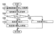
- FIG. 3 is a flowchart of a routine executed by the ECU 60 in order to make the determination.
- the reference intake pipe pressure Pm_t corresponding to the current intake valve timing InVT is acquired (step 100).
- the reference intake pipe pressure Pm_t changes according to the intake valve timing InVT, but does not depend on the exhaust valve timing ExVT.
- the ECU 60 stores a map that represents the relationship between the intake valve timing InVT and the reference intake pipe pressure Pm_t that has been examined in advance through experiments.
- the reference intake pipe pressure Pm_t is calculated based on the map and the current intake valve timing InVT detected by the cam position sensor 48.
- a map of the reference intake pipe pressure Pm_t including the relationship with the engine speed is created and the crank
- the reference intake pipe pressure Pm_t may be calculated in consideration of the current engine speed detected by the angle sensor 62.
- the current intake pipe pressure Pm is acquired (step 102).
- the current intake pipe pressure Pm can be detected by the intake pipe pressure sensor 64.
- the current intake pipe pressure Pm may be acquired by a known estimation method using an intake system physical model or the like. An example of a physical model of the intake system will be described in a fourth embodiment described later.
- the reference intake pipe pressure Pm_t acquired in step 100 is compared with the intake pipe pressure Pm acquired in step 102 (step 104). As a result of the comparison, if the intake pipe pressure Pm is equal to or lower than the reference intake pipe pressure Pm_t, it is determined that no fresh air is blown out (step 106). On the other hand, when the intake pipe pressure Pm is higher than the reference intake pipe pressure Pm_t, it is determined that a blow-through of fresh air has occurred (step 108).
- the blow-through amount Mex is calculated (step 110).
- a cylinder fresh air amount M cylinder is calculated.
- the in-cylinder fresh air amount M cylinder is calculated according to the above equation (4) based on the intake pipe pressure Pm, the in-cylinder volume Vc when the intake valve is closed, which is determined according to the intake valve timing InVT, and the intake air temperature Tc. be able to.
- the intake air temperature Tc a value detected by an intake air temperature sensor (not shown) or a value estimated by a known estimation method may be used.
- the intake valve passing fresh air amount Mc is calculated as follows.
- the ECU 60 stores in advance a Pm-Mc relation map in which maps as shown in FIG. 2 are collected for different intake valve timings InVT.
- the Pm-Mc relationship map Using the Pm-Mc relationship map, the Pm-Mc relationship corresponding to the current intake valve timing InVT and the exhaust valve timing ExVT can be obtained.
- the intake valve passing fresh air amount Mc can be calculated.
- the blow-through amount Mex can be calculated according to the above equation (5) based on the in- cylinder fresh air amount M cylinder and the intake valve passing fresh air amount Mc calculated as described above.
- the presence or absence of fresh air can be accurately determined with a simple configuration, and the blow-by amount Mex can be accurately calculated. For this reason, if the contents of control for the internal combustion engine 10 are corrected according to the determination result and the calculated value of the blow-by amount Mex, various characteristics such as fuel consumption and emission can be improved.
- the intake pipe pressure sensor 64 corresponds to the “intake pipe pressure acquisition means” in the first invention
- the ECU 60 corresponds to the “storage means” in the first invention.
- the “reference intake pipe pressure acquisition means” in the first invention executes the processes of steps 104, 106, and 108, thereby executing the process of the first invention.
- the “blow-through determination means” in the second embodiment implements the processing of step 110 described above, thereby realizing the “blow-through amount calculation means” in the second invention.
- Embodiment 2 FIG. Next, a second embodiment of the present invention will be described with reference to FIG. 4. The description will focus on the differences from the first embodiment described above, and the same matters will be simplified or described. Omitted.
- FIG. 4 is a flowchart of a routine executed by the ECU 60 in the present embodiment in order to realize the above function. According to the routine shown in FIG. 4, it is first determined whether or not fresh air has been blown (step 120). In this step 120, it is possible to determine the presence or absence of fresh air by performing the same processing as in steps 100 to 108 in FIG.
- step 120 normal fuel injection control is executed as follows. First, the fuel injection amount is calculated by dividing the intake valve passing fresh air amount Mc by the target air-fuel ratio (step 122). The intake valve passing fresh air amount Mc is calculated by the method described in the description of step 110 in FIG. Subsequently, the amount of fuel calculated in step 122 is injected in a normal procedure (step 124). The injection timing in step 124 is a normal injection timing set in advance. Further, in the case of an internal combustion engine provided with a port injector (not shown) for injecting fuel into the intake port in addition to the in-cylinder injector 20, the amount of fuel calculated in step 122 is supplied to the in-cylinder injector 20. It may be shared by the port injector or injected, or the entire amount may be injected from the port injector.
- the air-fuel ratio in the cylinder can be matched with the target air-fuel ratio by calculating the fuel injection amount by the method of step 122 described above.
- step 120 when it is determined in step 120 that there is a blow-through, the following fuel injection control is executed.
- the fuel injection amount is calculated by dividing the in- cylinder fresh air amount M cylinder by the target air-fuel ratio (step 126).
- the in-cylinder fresh air amount M cylinder is calculated by the method described in the description of step 110 in FIG.
- the amount of fuel calculated in step 126 is injected from the in-cylinder injector 20 in the intake stroke or compression stroke after the exhaust valve 16 is closed (step 128).
- the intake valve passing fresh air amount Mc includes a blow-through amount Mex in addition to the in- cylinder fresh air amount M cylinder .
- the fuel injection amount is calculated from the intake valve passing fresh air amount Mc and the target air-fuel ratio, so that the air-fuel ratio in the cylinder is changed to the target air-fuel ratio. Can match.
- fuel is injected from the in-cylinder injector 20 after the exhaust valve 16 is closed.
- a port injector is provided. In the case of an internal combustion engine, fuel may be injected from the port injector after the exhaust valve 16 is closed and before the intake valve 14 is closed (intake stroke). During this period, even if the injection is from the port injector, the fuel can flow into the cylinder.
- the in-cylinder injector 20 is the same as the “fuel injection device” in the fourth invention and the “in-cylinder fuel injection device” in the fifth invention. This corresponds to the “new air inflow amount” in the sixth invention.
- the ECU 60 executes the process of step 126
- the “in-cylinder fresh air amount calculating means” and the “first fuel injection amount calculating means” in the fourth aspect of the invention execute the process of step 128.
- the “injection control means” in the fourth and fifth inventions executes the processing of step 122 described above, whereby “fresh air inflow amount calculating means” and “second fuel injection” in the sixth invention are performed.
- the “quantity calculation means” executes the processing of step 128, thereby realizing the “injection control means” according to the sixth aspect of the present invention.
- Embodiment 3 FIG. Next, a third embodiment of the present invention will be described with reference to FIG. 5. The description will focus on the differences from the first and second embodiments described above, and the description of the same matters will be simplified. Or omit.
- a NOx occlusion reduction type three-way catalyst 42 is installed in the exhaust passage 24 of the internal combustion engine 10 of the present embodiment shown in FIG.
- NOx in the exhaust gas can be captured and stored by the NOx storage-reduction three-way catalyst 42.
- the ECU 60 calculates the amount of NOx stored in the NOx storage reduction type three-way catalyst 42 by a known method.
- the ECU 60 executes rich spike control for temporarily setting the target air-fuel ratio to a rich air-fuel ratio equal to or lower than the stoichiometric air-fuel ratio before the calculated NOx storage amount reaches the limit value.
- the rich spike control the exhaust gas having a rich air-fuel ratio equal to or lower than the stoichiometric air-fuel ratio flows into the NOx storage reduction type three-way catalyst 42.
- the unburned components such as HC and CO contained in the exhaust gas
- the NOx stored in the NOx storage reduction type three-way catalyst 42 is reduced and purified to N 2 and released.
- the NOx occlusion reduction type three-way catalyst 42 can again capture NOx, and the internal combustion engine 10 can be returned to the lean burn operation.
- the fuel injection amount is calculated from the in- cylinder fresh air amount M cylinder and the target air-fuel ratio, and the exhaust valve 16 is Control is performed so that fuel is injected from the in-cylinder injector 20 after closing.
- this control is performed during the execution of the rich spike, lean blow-through fresh air that does not contain fuel flows into the NOx occlusion reduction type three-way catalyst 42, so that the NOx reduction efficiency may decrease.
- the air-fuel ratio in the cylinder matches the target air-fuel ratio, but the air-fuel ratio of the entire exhaust gas including the fresh air blown through Becomes leaner than the target air-fuel ratio. That is, the air-fuel ratio of the exhaust gas flowing into the NOx occlusion reduction type three-way catalyst 42 becomes leaner than the target air-fuel ratio. This also reduces the NOx reduction efficiency.
- the fuel injection amount is calculated from the intake valve passing fresh air amount Mc and the target air-fuel ratio during execution of the rich spike regardless of whether or not fresh air is blown through. Was decided to be calculated.
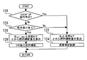
- FIG. 5 is a flowchart of a routine executed by the ECU 60 in the present embodiment in order to realize the above function.
- the routine shown in FIG. 5 is the same as the routine shown in FIG. 4 except that step 118 is added before step 120.
- it is first determined whether or not rich spike control is being executed (step 118). If it is determined in step 118 that the rich spike control is not being executed, the processing from step 120 onward is executed. The contents are the same as in the second embodiment.
- step 118 if it is determined in step 118 that the rich spike control is being executed, the processing from step 122 onward is executed. That is, the fuel injection amount is calculated from the intake valve passing fresh air amount Mc and the target air-fuel ratio (step 122), and the calculated amount of fuel is injected in the normal procedure (step 124). Since the processing of the routine shown in FIG. 5 is the same as the routine of FIG. 4 of the second embodiment described above except for the points described above, further description is omitted.
- the fuel injection amount is calculated from the intake valve passing fresh air amount Mc and the target air-fuel ratio even when fresh air blow-through has occurred. Therefore, the air-fuel ratio of the entire exhaust gas including the fresh air blown through can be matched with the target air-fuel ratio. For this reason, the exhaust gas having a predetermined rich air-fuel ratio set in the rich spike control can surely flow into the NOx occlusion reduction type three-way catalyst 42, so that a good NOx reduction efficiency can be obtained.
- the ECU 60 executes the above-described rich spike control so that the “rich spike control means” in the seventh invention executes the routine shown in FIG.
- the “injection control means” according to the seventh aspect of the invention is realized.
- Embodiment 4 FIG. Next, the fourth embodiment of the present invention will be described with reference to FIGS. 6 to 8. The difference from the first and second embodiments described above will be mainly described, and the same matters will be described. The description is simplified or omitted.
- the intake pipe pressure sensor 64 is provided as a method for acquiring the intake pipe pressure Pm, and the intake pipe pressure Pm is directly detected.
- the intake pipe pressure Pm is estimated using a physical model (air model) of the intake system as described below.
- the pressure upstream of the compressor 26a (hereinafter referred to as “compressor upstream pressure”) is Pa, and the pressure downstream of the intercooler 32 (upstream of the throttle valve 34) (hereinafter referred to as “supercharging pressure”).
- Pic the flow rate of fresh air passing through the compressor 26a (hereinafter referred to as “compressor flow rate”) Mcp, and the flow rate of fresh air passing through the throttle valve 34 (hereinafter referred to as “throttle flow rate”) as Mt.
- the ECU 60 updates the values of the intake pipe pressure Pm and other physical quantities of the intake system by repeatedly executing a procedure calculation described below at predetermined intervals.
- the throttle flow rate Mt is calculated by the following equation.
- Mt f (Pm / Pic) (6)
- f (x) means a function of x.
- the intake pipe pressure Pm and the supercharging pressure Pic are values currently stored in the memory, that is, values obtained by the previous calculation.
- the intake valve passing fresh air amount Mc is based on the value of the intake pipe pressure Pm currently stored in the memory (the value of the intake pipe pressure Pm obtained in the previous calculation) and the Pm-Mc relationship map described above. Is calculated.
- Pic Pic (previous value) + K ⁇ (Mcp ⁇ Mt) (7)
- Mt is a value previously calculated by the above equation (6).
- Mcp is a value calculated using a compressor model described later.
- K is a constant.
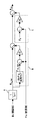
- FIG. 6 is a block diagram showing a compressor model used in the present embodiment.
- the compressor flow rate Mcp is calculated based on the intake valve passing fresh air amount Mc (previous value), the supercharging pressure Pic (previous value), and the compressor upstream pressure Pa.
- the compressor upstream pressure Pa is measured by an atmospheric pressure sensor (not shown).
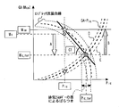
- FIG. 7 is a diagram showing a calculation method of the compressor flow rate Mcp by the compressor model shown in FIG.
- a curve GA-Pic that rises to the right in FIG. 7 is a curve showing the relationship between the intake air flow rate GA and the supercharging pressure Pic in a steady operation state.
- the ECU 60 stores in advance a result of examining this relationship through an experiment as a map. This map is hereinafter referred to as “GA-Pic steady map”.
- the plurality of lower right curves in FIG. 7 are compressor flow rate curves at the same turbo speed. The compressor flow rate curve shifts to the high pressure side and the high flow rate side as the turbo rotational speed increases.
- the compressor model has a first-order lag element A, a section B, and a section C.
- the first-order lag element A receives the intake valve passing fresh air amount Mc (previous value) and outputs Mc_tar.
- Mc previously value
- Mc_tar fresh air amount
- section B of the compressor model first, using the GA-Pic steady map, the supercharging pressure value Pic_tar corresponding to the Mc_tar is calculated on the GA-Pic steady map. Then, a value obtained by multiplying the difference between the calculated Pic_tar and the supercharging pressure Pic (previous value) by the gain G1 is calculated. This section B is to calculate a correction value for correcting the flow rate difference due to the deviation from the GA-Pic steady map.
- section C of the compressor model a value obtained by multiplying the difference between the compressor upstream pressure Pa and the supercharging pressure Pic (previous value) by the gain G2 is calculated.
- the compressor flow rate Mcp increases rapidly. This section C is to calculate a correction value to cope with such a sudden increase in the compressor flow rate Mcp in the region of Pic ⁇ Pa.
- the compressor flow rate Mcp is calculated by adding the correction value calculated in the section B and the correction value calculated in the section C to the Mc_tar.
- processing by the first-order lag element A is indicated by an arrow A
- processing by section B is indicated by an arrow B.
- the GA-Pic steady map is assumed to have a single line, that is, a one-to-one correspondence relationship.
- the intake flow rate GA is the same, the magnitude of the exhaust energy may differ, and as a result, the supercharging pressure Pic may differ.
- the one-to-one relationship in the steady operation state is actually the relationship between the supercharging pressure Pic and the turbo speed, and the magnitude of the exhaust energy is different even if the intake flow rate GA is the same. This is probably because the turbo rotation speed is different.
- the GA-Pic steady map and the time constant T of the first-order lag element A are corrected according to the blow-by amount Mex.
- FIG. 8 is a flowchart of a routine executed by the ECU 60 in the present embodiment in order to realize the above function.
- the routine shown in FIG. 8 first, it is determined whether or not fresh air is blown through (step 130).
- the presence or absence of fresh air is determined by performing substantially the same processing as in steps 100 to 108 in FIG.
- the present embodiment is different from the first embodiment in that the presence or absence of blow-by is determined by comparing the intake pipe pressure Pm estimated using the air model described above with the reference intake pipe pressure Pm_t.
- step 130 the blow-through amount Mex is then calculated (step 132).
- step 132 the blow-by amount Mex can be calculated in the same manner as in step 110 of FIG.
- step 134 the GA-Pic steady map is corrected in the direction in which the supercharging pressure Pic in the GA-Pic steady map decreases (step 134). That is, the GA-Pic steady map is corrected to a curve indicated by D in FIG. 7, for example.
- the correction amount in step 134 is increased as the blow-through amount Mex calculated in step 132 is increased.
- step 136 the time constant T of the first-order lag element A is corrected (step 136).
- the time constant T of the first-order lag element A is corrected in the direction of increasing when the internal combustion engine 10 in which the turbo rotational speed increases, and 1 in the deceleration of the internal combustion engine 10 in which the turbo rotational speed decreases.
- the time constant T of the next delay element A is corrected so as to be shortened.
- the correction amount is increased as the blow-through amount Mex calculated in step 132 is increased.
- the effect of the reduction in exhaust energy due to the blow-through of fresh air can be appropriately reflected in the compressor model. For this reason, even when fresh air is blown out, the compressor flow rate Mcp can be accurately estimated, and as a result, the intake pipe pressure Pm can be accurately estimated.
- the time constant T is the “time constant” in the eighth and ninth inventions
- the GA-Pic steady map is the “map” in the eighth and ninth inventions. Mex corresponds to the “parameter” in the eighth and ninth inventions, respectively.
- the “compressor flow rate estimating means” in the eighth invention executes the processing of step 132, thereby performing the “blow-through amount” in the ninth invention.
- the “computation means” executes the processing of steps 134 and 136, thereby realizing the “compressor model correction means” in the eighth and ninth inventions, respectively.
- Embodiment 5 FIG. Next, a fifth embodiment of the present invention will be described with reference to FIG. 9. The description will focus on the differences from the fourth embodiment described above, and the same matters will be simplified or described. Omitted.
- the internal EGR can be performed by changing the intake valve timing InVT and the exhaust valve timing ExVT.
- the fourth embodiment it is desirable to perform correction according to the magnitude of the exhaust energy in order to increase the estimation accuracy of the compressor flow rate Mcp using the compressor model.
- EGR amount exhaust gas recirculation amount
- Mex fresh air blow-out amount
- the intake flow rate GA is the same, the exhaust gas energy decreases as the EGR amount increases. This is because as the EGR amount increases, the amount of inert gas in the cylinder increases, so that the combustion temperature decreases. Therefore, in the present embodiment, the GA-Pic steady map and the time constant T of the first-order lag element A are corrected in accordance with the EGR amount in order to appropriately reflect the effect of EGR on the compressor model.
- FIG. 9 is a flowchart of a routine executed by the ECU 60 in the present embodiment in order to realize the above function.
- the routine shown in FIG. 9 first, it is determined whether or not EGR is being executed (step 140). In the case of an internal combustion engine equipped with an external EGR device (not shown), it is determined in step 140 that at least one of the external EGR and the internal EGR is being executed. Is done.
- step 140 If it is determined in step 140 that the EGR is being executed, the EGR amount is then acquired (step 142). In the case of an internal combustion engine equipped with an external EGR device, in this step 142, not only the internal EGR amount but also the EGR amount including the external EGR amount is acquired. Since the calculation method of the EGR amount is known, the description thereof is omitted.
- the GA-Pic steady map is corrected in the direction in which the supercharging pressure Pic in the GA-Pic steady map decreases (step 144). That is, the GA-Pic steady map is corrected to a curve indicated by D in FIG. 7, for example.
- the correction amount in step 144 is increased as the EGR amount calculated in step 142 is larger.
- the time constant T of the first-order lag element A is corrected (step 146).
- the time constant T of the first-order lag element A is corrected in the direction of increasing when the internal combustion engine 10 in which the turbo rotational speed increases, and the first-order lag element in the deceleration of the internal combustion engine 10 in which the turbo rotational speed decreases.
- the time constant T of A is corrected so as to be shortened.
- the correction amount is increased as the EGR amount acquired in step 142 is increased.
- the effect of the exhaust energy reduction due to EGR can be appropriately reflected in the compressor model. For this reason, even during execution of EGR, the compressor flow rate Mcp can be accurately estimated, and hence the intake pipe pressure Pm can be accurately estimated.
- variable intake valve operating apparatus 44 and the variable exhaust valve operating apparatus 46 that enable internal EGR are used as the “exhaust gas recirculation means” in the tenth aspect of the present invention. It corresponds to the “parameter” in the present invention. Further, when the ECU 60 executes the process of step 142, the “exhaust gas recirculation amount acquisition means” in the tenth invention executes the processes of steps 144 and 146, thereby enabling the “compressor” in the tenth invention. "Model correction means" is realized respectively.
- Embodiment 6 FIG. Next, the sixth embodiment of the present invention will be described with reference to FIG. 10. The description will focus on the differences from the fourth embodiment described above, and the same matters will be simplified or described. Omitted.
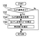
- the exhaust valve timing ExVT is a parameter that affects the magnitude of exhaust energy. This is because the later the timing at which the exhaust valve 16 opens, the more work the combustion gas in the cylinder gives to the piston 12, but the smaller the exhaust energy. Therefore, in the present embodiment, in order to appropriately reflect the influence of the delay of the opening timing of the exhaust valve 16 on the compressor model, the GA-Pic steady map and the first-order delay according to the amount of retardation of the exhaust valve timing ExVT. The time constant T of the element A was corrected.
- FIG. 10 is a flowchart of a routine executed by the ECU 60 in the present embodiment in order to realize the above function.
- the routine shown in FIG. 10 it is first determined whether or not the exhaust valve timing ExVT is retarded (step 150). If it is determined in step 150 that the exhaust valve timing ExVT is retarded, then the retard amount of the exhaust valve timing ExVT is acquired (step 152). Subsequently, the GA-Pic steady map is corrected in such a direction that the supercharging pressure Pic in the GA-Pic steady map decreases (step 154). That is, the GA-Pic steady map is corrected to a curve indicated by D in FIG. 7, for example. The correction amount in step 154 is increased as the retardation amount of the exhaust valve timing ExVT acquired in step 152 is larger.
- step 156 the time constant T of the first-order lag element A is corrected (step 156).
- step 156 the time constant T of the first-order lag element A is corrected in the direction of increasing when the internal combustion engine 10 in which the turbo rotational speed increases, and the first-order lag element in the deceleration of the internal combustion engine 10 in which the turbo rotational speed decreases.
- the time constant T of A is corrected so as to be shortened.
- the correction amount is increased as the retardation amount of the exhaust valve timing ExVT calculated in step 152 is increased.
- the retard amount of the exhaust valve timing ExVT corresponds to the “parameter” in the eleventh aspect of the invention.
- the “compressor model correcting means” according to the eleventh aspect of the present invention is realized by the ECU 60 executing the processing of steps 154 and 156.
- Embodiment 7 FIG. Next, a seventh embodiment of the present invention will be described with reference to FIG. 11. The description will focus on the differences from the fourth embodiment described above, and the same matters will be simplified or described. Omitted.
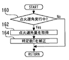
- the ECU 60 executes ignition timing retarding control for retarding the ignition timing from the normal ignition timing in order to prevent knocking during the transient operation of the internal combustion engine 10.
- ignition retard amount the retard amount of the ignition timing with respect to the normal ignition timing when the ignition timing retard control is executed.
- the ignition retardation amount is a parameter that affects the magnitude of the exhaust energy. This is because the exhaust temperature increases and the exhaust energy increases as the ignition retard amount increases. When the exhaust energy increases due to the ignition delay angle, the speed of increase in the turbo speed increases and the speed of decrease in the turbo speed decreases. Therefore, in the present embodiment, the time constant T of the primary delay element A is corrected according to the ignition delay amount in order to appropriately reflect the influence of the ignition delay in the compressor model.
- the ignition timing retardation control in the present embodiment is a control that is executed only during a transient operation, and therefore correction of the GA-Pic steady map is unnecessary.
- FIG. 11 is a flowchart of a routine executed by the ECU 60 in the present embodiment in order to realize the above function.
- the routine shown in FIG. 11 it is first determined whether or not the ignition timing retardation control is being executed (step 160). If it is determined in step 160 that the ignition timing retard control is being executed, the ignition retard amount is then acquired (step 162). Subsequently, the time constant T of the primary delay element A is corrected (step 164). In this step 164, the time constant T of the first-order lag element A is corrected in the direction of shortening when the internal combustion engine 10 in which the turbo rotational speed increases, and the first-order lag element in the deceleration of the internal combustion engine 10 in which the turbo speed decreases. The time constant T of A is corrected so as to increase. The correction amount is increased as the ignition retard amount calculated in step 162 is larger.
- the effect of the increase in exhaust energy due to the ignition delay can be appropriately reflected in the compressor model. For this reason, even when the ignition timing retardation control is being executed, the compressor flow rate Mcp can be accurately estimated, and as a result, the intake pipe pressure Pm can be accurately estimated.
- the ignition retard amount corresponds to the “parameter” in the eleventh aspect of the invention.
- the “ignition timing retarding amount obtaining means” in the eleventh aspect of the invention executes the process of step 164 so that the “compressor model correction” of the eleventh aspect of the invention is achieved. Each means is realized.
Abstract
Description
吸気通路内の空気を圧縮するコンプレッサを有する過給機と、
吸気管圧力を検出または推定する吸気管圧力取得手段と、
吸気弁のバルブタイミングを可変とする吸気可変動弁装置と、
排気弁のバルブタイミングを可変とする排気可変動弁装置と、
前記吸気弁のバルブタイミングに依存する値であって前記排気弁のバルブタイミングには依存しない値である基準吸気管圧力に関する情報を記憶した記憶手段と、
前記記憶手段に記憶された情報に基づいて、前記吸気弁のバルブタイミングに対応した基準吸気管圧力を取得する基準吸気管圧力取得手段と、
前記吸気管圧力取得手段により検出または推定された吸気管圧力と、前記基準吸気管圧力取得手段により取得された基準吸気管圧力とを比較した結果に基づいて、排気側への新気の吹き抜けの有無を判定する吹き抜け判定手段と、
を備えることを特徴とする。 In order to achieve the above object, a first invention is a control device for an internal combustion engine,
A supercharger having a compressor for compressing air in the intake passage;
Intake pipe pressure acquisition means for detecting or estimating the intake pipe pressure;
An intake variable valve operating device that makes the valve timing of the intake valve variable;
An exhaust variable valve operating device that makes the valve timing of the exhaust valve variable;
Storage means for storing information related to a reference intake pipe pressure, which is a value that depends on the valve timing of the intake valve and that does not depend on the valve timing of the exhaust valve;
Reference intake pipe pressure acquisition means for acquiring a reference intake pipe pressure corresponding to the valve timing of the intake valve based on information stored in the storage means;
Based on the result of comparison between the intake pipe pressure detected or estimated by the intake pipe pressure acquisition means and the reference intake pipe pressure acquired by the reference intake pipe pressure acquisition means, the flow of fresh air to the exhaust side is reduced. Blow-through determination means for determining presence or absence;
It is characterized by providing.
前記吹き抜け判定手段により吹き抜けがあると判定された場合に、前記吸気管圧力取得手段により検出または推定された吸気管圧力に基づいて、排気側へ吹き抜ける新気の量を算出する吹き抜け量算出手段を備えることを特徴とする。 The second invention is the first invention, wherein
A blow-off amount calculating means for calculating the amount of fresh air blown to the exhaust side based on the intake pipe pressure detected or estimated by the intake pipe pressure acquiring means when the blow-through determining means determines that there is a blow-through. It is characterized by providing.
前記基準吸気管圧力は、前記吸気弁のバルブタイミングを一定として前記排気弁のバルブタイミングを遅角したときに前記吸気弁から流入する新気の量が減少する領域と、前記吸気弁のバルブタイミングを一定として前記排気弁のバルブタイミングを遅角したときに前記吸気弁から流入する新気の量が増加する領域との境界の値であることを特徴とする。 The third invention is the first or second invention, wherein
The reference intake pipe pressure includes a region in which the amount of fresh air flowing from the intake valve decreases when the valve timing of the exhaust valve is retarded while the valve timing of the intake valve is constant, and the valve timing of the intake valve Is a boundary value with a region where the amount of fresh air flowing from the intake valve increases when the valve timing of the exhaust valve is retarded.
燃料噴射装置と、
前記吹き抜け判定手段により吹き抜けがあると判定された場合に、前記吸気管圧力取得手段により検出または推定された吸気管圧力に基づいて、気筒内に充填される新気の量を算出する筒内新気量算出手段と、
前記筒内新気量算出手段により算出された筒内新気量と、目標空燃比とに基づいて、燃料噴射量を算出する第1の燃料噴射量算出手段と、
前記吹き抜け判定手段により吹き抜けがあると判定された場合に、前記第1の燃料噴射量算出手段により算出された量の燃料を、前記排気弁が閉じた後に前記燃料噴射装置に噴射させる噴射制御手段と、
を備えることを特徴とする。 According to a fourth invention, in any one of the first to third inventions,
A fuel injection device;
In-cylinder freshness that calculates the amount of fresh air to be filled in the cylinder based on the intake pipe pressure detected or estimated by the intake pipe pressure acquisition means when the blow-by determination means determines that there is a blow-through. A volume calculation means;
First fuel injection amount calculating means for calculating a fuel injection amount based on the in-cylinder fresh air amount calculated by the in-cylinder fresh air amount calculating means and a target air-fuel ratio;
Injection control means for causing the fuel injection device to inject the amount of fuel calculated by the first fuel injection amount calculating means after the exhaust valve is closed when the blow-by determining means determines that there is a blow-through. When,
It is characterized by providing.
前記燃料噴射装置は、気筒内に直接に燃料を噴射する筒内燃料噴射装置を含み、
前記噴射制御手段は、前記吹き抜け判定手段により吹き抜けがあると判定された場合には、前記第1の燃料噴射量算出手段により算出された量の燃料を前記筒内燃料噴射装置に噴射させることを特徴とする。 The fifth invention is the fourth invention, wherein
The fuel injection device includes an in-cylinder fuel injection device that directly injects fuel into a cylinder,
The injection control means causes the in-cylinder fuel injection device to inject the amount of fuel calculated by the first fuel injection amount calculation means when the blow-by determination means determines that there is a blow-through. Features.
前記吸気弁から流入する新気の量を算出する新気流入量算出手段と、
前記新気流入量算出手段により算出された新気流入量と、目標空燃比とに基づいて、燃料噴射量を算出する第2の燃料噴射量算出手段と、
を備え、
前記噴射制御手段は、前記吹き抜け判定手段により吹き抜けがないと判定された場合には、前記第2の燃料噴射量算出手段により算出された量の燃料を前記燃料噴射装置に噴射させることを特徴とする。 The sixth invention is the fourth or fifth invention, wherein
Fresh air inflow amount calculating means for calculating the amount of fresh air flowing from the intake valve;
Second fuel injection amount calculating means for calculating a fuel injection amount based on the fresh air inflow amount calculated by the fresh air inflow amount calculating means and a target air-fuel ratio;
With
The injection control means causes the fuel injection device to inject the amount of fuel calculated by the second fuel injection amount calculation means when it is determined by the blow-by determination means that there is no blow-through. To do.
排気ガスの空燃比を一時的にリッチにするリッチスパイク制御を必要時に実行するリッチスパイク制御手段を備え、
前記噴射制御手段は、前記リッチスパイク制御手段によりリッチスパイク制御が実行される場合には、前記吹き抜け判定手段の判定結果にかかわらず、前記第2の燃料噴射量算出手段により算出された量の燃料を前記燃料噴射装置に噴射させることを特徴とする。 The seventh invention is the sixth invention, wherein
Rich spike control means for performing rich spike control to temporarily enrich the air-fuel ratio of exhaust gas when necessary,
When the rich spike control is executed by the rich spike control means, the injection control means has the amount of fuel calculated by the second fuel injection amount calculation means regardless of the determination result of the blow-by determination means. Is injected into the fuel injection device.
前記過給機は、排気ガスの流れによって作動するタービンで前記コンプレッサを駆動するものであり、
過渡運転状態における吸気流量の変化に対する前記過給機の回転数の変化の遅れに関する時定数と、定常運転状態における吸気流量と過給圧との関係を表すマップとを含むコンプレッサモデルに基づいて、前記コンプレッサを通過する新気の流量を推定するコンプレッサ流量推定手段を備え、
前記コンプレッサ流量推定手段は、排気エネルギーの大きさに影響を及ぼすパラメータに基づいて、前記時定数と、前記マップとの少なくとも一方を補正するコンプレッサモデル補正手段を含むことを特徴とする。 Further, an eighth invention is any one of the first to seventh inventions,
The supercharger drives the compressor with a turbine that is operated by a flow of exhaust gas.
Based on a compressor model including a time constant relating to a delay in the change in the rotational speed of the turbocharger with respect to a change in the intake air flow rate in a transient operation state, and a map representing a relationship between the intake air flow rate and the supercharging pressure in a steady operation state, A compressor flow rate estimating means for estimating a flow rate of fresh air passing through the compressor;
The compressor flow rate estimating means includes compressor model correcting means for correcting at least one of the time constant and the map based on a parameter affecting the magnitude of exhaust energy.
前記吹き抜け判定手段により吹き抜けがあると判定された場合に、前記吸気管圧力取得手段により検出または推定された吸気管圧力に基づいて、排気側へ吹き抜ける新気の量を算出する吹き抜け量算出手段を備え、
前記コンプレッサモデル補正手段は、前記吹き抜け量算出手段により算出された吹き抜け量を前記パラメータとして、前記時定数および前記マップを補正する手段を含むことを特徴とする。 The ninth invention is the eighth invention, wherein
A blow-off amount calculating means for calculating the amount of fresh air blown to the exhaust side based on the intake pipe pressure detected or estimated by the intake pipe pressure acquiring means when the blow-through determining means determines that there is a blow-through. Prepared,
The compressor model correcting means includes means for correcting the time constant and the map using the blow-through amount calculated by the blow-through amount calculating means as the parameter.
排気ガス再循環を可能とする排気ガス再循環手段と、
排気ガス再循環量を取得する排気ガス再循環量取得手段と、
を備え、
前記コンプレッサモデル補正手段は、前記排気ガス再循環量取得手段により取得された排気ガス再循環量を前記パラメータとして、前記時定数および前記マップを補正する手段を含むことを特徴とする。 The tenth aspect of the invention is the eighth aspect of the invention,
Exhaust gas recirculation means for enabling exhaust gas recirculation;
An exhaust gas recirculation amount acquisition means for acquiring an exhaust gas recirculation amount;
With
The compressor model correction means includes means for correcting the time constant and the map using the exhaust gas recirculation amount acquired by the exhaust gas recirculation amount acquisition means as the parameter.
前記コンプレッサモデル補正手段は、前記排気弁のバルブタイミングを前記パラメータとして、前記時定数および前記マップを補正する手段を含むことを特徴とする。 The eleventh aspect of the invention is the eighth aspect of the invention,
The compressor model correcting means includes means for correcting the time constant and the map using the valve timing of the exhaust valve as the parameter.
実際の点火時期が通常点火時期に対して遅角されている場合に、その点火時期遅角量を取得する点火時期遅角量取得手段を備え、
前記コンプレッサモデル補正手段は、前記点火時期遅角量を前記パラメータとして、前記時定数を補正する手段を含むことを特徴とする。 The twelfth invention is the eighth invention, wherein
When the actual ignition timing is retarded with respect to the normal ignition timing, the ignition timing retardation amount obtaining means for obtaining the ignition timing retardation amount is provided,
The compressor model correcting means includes means for correcting the time constant using the ignition timing retardation amount as the parameter.
図1は、本発明の実施の形態1のシステム構成を説明するための図である。図1に示すように、本発明の実施の形態1のシステムは、内燃機関10を備えている。本実施形態の内燃機関10は、火花点火式で、且つリーンバーン運転が可能なものとする。内燃機関10の気筒数および気筒配置は特に限定されない。図1には、一つの気筒のみが代表して描かれている。
FIG. 1 is a diagram for explaining a system configuration according to the first embodiment of the present invention. As shown in FIG. 1, the system according to the first embodiment of the present invention includes an
Pm・Vc=(Mc+Me)Rc・Tc ・・・(1) When the internal EGR amount is generated and the internal EGR amount is Me, the amount of gas charged in the cylinder is the sum of the intake valve passing fresh air amount Mc and the internal EGR amount Me. Considering that the in-cylinder pressure Pc at the time when the
Pm · Vc = (Mc + Me) Rc · Tc (1)
Mc={Vc/(Rc・Tc)}Pm-Me ・・・(2) However, Vc is the cylinder volume when the
Mc = {Vc / (Rc · Tc)} Pm−Me (2)
Pm・Vc=Mcylinder・Rc・Tc ・・・(3) When fresh air is blown out, the exhaust gas does not flow back through the
Pm · Vc = M cylinder · Rc · Tc (3)
Mcylinder={Vc/(Rc・Tc)}Pm ・・・(4) Therefore, the in-cylinder fresh air amount M cylinder when the fresh air blow-through occurs can be calculated by the following equation obtained by modifying the above equation (3).
M cylinder = {Vc / (Rc · Tc)} Pm (4)
Mex=Mc-Mcylinder ・・・(5) It can be considered that the intake valve passing fresh air amount Mc when the fresh air blow-through occurs is the sum of the in- cylinder fresh air amount M cylinder and the blow-through amount Mex. That is, the blow-through amount Mex can be considered as a value obtained by subtracting the in- cylinder fresh air amount M cylinder from the intake valve passing fresh air amount Mc. Therefore, the blow-by amount Mex can be calculated by the following equation.
Mex = Mc−M cylinder (5)
次に、図4を参照して、本発明の実施の形態2について説明するが、上述した実施の形態1との相違点を中心に説明し、同様の事項については、その説明を簡略化または省略する。 Embodiment 2. FIG.
Next, a second embodiment of the present invention will be described with reference to FIG. 4. The description will focus on the differences from the first embodiment described above, and the same matters will be simplified or described. Omitted.
次に、図5を参照して、本発明の実施の形態3について説明するが、上述した実施の形態1および2との相違点を中心に説明し、同様の事項については、その説明を簡略化または省略する。 Embodiment 3 FIG.
Next, a third embodiment of the present invention will be described with reference to FIG. 5. The description will focus on the differences from the first and second embodiments described above, and the description of the same matters will be simplified. Or omit.
次に、図6乃至図8を参照して、本発明の実施の形態4について説明するが、上述した実施の形態1および2との相違点を中心に説明し、同様の事項については、その説明を簡略化または省略する。 Embodiment 4 FIG.
Next, the fourth embodiment of the present invention will be described with reference to FIGS. 6 to 8. The difference from the first and second embodiments described above will be mainly described, and the same matters will be described. The description is simplified or omitted.
Mt=f(Pm/Pic) ・・・(6)
上記(6)式において、f(x)は、xの関数を意味する。また、吸気管圧力Pm、過給圧Picは、現時点においてメモリに記憶されている値、すなわち、前回の計算で得られた値である。 The throttle flow rate Mt is calculated by the following equation.
Mt = f (Pm / Pic) (6)
In the above equation (6), f (x) means a function of x. Further, the intake pipe pressure Pm and the supercharging pressure Pic are values currently stored in the memory, that is, values obtained by the previous calculation.
Pic=Pic(前回値)+K・(Mcp-Mt) ・・・(7)
上記(7)式において、スロットル流量Mtは、先に上記(6)式で計算された値である。コンプレッサ流量Mcpは、後述するコンプレッサモデルを用いて算出された値である。Kは定数である。 For updating the supercharging pressure Pic, calculation according to the following equation is used.
Pic = Pic (previous value) + K · (Mcp−Mt) (7)
In the above equation (7), the throttle flow rate Mt is a value previously calculated by the above equation (6). The compressor flow rate Mcp is a value calculated using a compressor model described later. K is a constant.
Pm=Pm(前回値)+Km・(Mt-Mc) ・・・(8)
(8)式において、スロットル流量Mt、先に上記(6)式で計算された値であり、吸気弁通過新気量Mcは、先にPm-Mc関係マップで計算された値である。Kmは定数である。 For the update of the intake pipe pressure Pm, calculation according to the following equation (8) is used.
Pm = Pm (previous value) + Km · (Mt−Mc) (8)
In the equation (8), the throttle flow rate Mt is a value previously calculated by the above equation (6), and the intake valve passing fresh air amount Mc is a value previously calculated by the Pm-Mc relationship map. Km is a constant.
次に、図9を参照して、本発明の実施の形態5について説明するが、上述した実施の形態4との相違点を中心に説明し、同様の事項については、その説明を簡略化または省略する。 Embodiment 5 FIG.
Next, a fifth embodiment of the present invention will be described with reference to FIG. 9. The description will focus on the differences from the fourth embodiment described above, and the same matters will be simplified or described. Omitted.
次に、図10を参照して、本発明の実施の形態6について説明するが、上述した実施の形態4との相違点を中心に説明し、同様の事項については、その説明を簡略化または省略する。 Embodiment 6 FIG.
Next, the sixth embodiment of the present invention will be described with reference to FIG. 10. The description will focus on the differences from the fourth embodiment described above, and the same matters will be simplified or described. Omitted.
次に、図11を参照して、本発明の実施の形態7について説明するが、上述した実施の形態4との相違点を中心に説明し、同様の事項については、その説明を簡略化または省略する。 Embodiment 7 FIG.
Next, a seventh embodiment of the present invention will be described with reference to FIG. 11. The description will focus on the differences from the fourth embodiment described above, and the same matters will be simplified or described. Omitted.
12 ピストン
14 吸気バルブ
16 排気バルブ
18 点火プラグ
20 筒内インジェクタ
22 吸気通路
24 排気通路
26 ターボ過給機
26a 吸気圧縮機
26b 排気タービン
30 エアフローメータ
32 インタークーラ
34 スロットル弁
36 サージタンク
42 NOx触媒
44 吸気可変動弁装置
46 排気可変動弁装置
48,50 カムポジションセンサ
60 ECU DESCRIPTION OF
Claims (12)
- 吸気通路内の空気を圧縮するコンプレッサを有する過給機と、
吸気管圧力を検出または推定する吸気管圧力取得手段と、
吸気弁のバルブタイミングを可変とする吸気可変動弁装置と、
排気弁のバルブタイミングを可変とする排気可変動弁装置と、
前記吸気弁のバルブタイミングに依存する値であって前記排気弁のバルブタイミングには依存しない値である基準吸気管圧力に関する情報を記憶した記憶手段と、
前記記憶手段に記憶された情報に基づいて、前記吸気弁のバルブタイミングに対応した基準吸気管圧力を取得する基準吸気管圧力取得手段と、
前記吸気管圧力取得手段により検出または推定された吸気管圧力と、前記基準吸気管圧力取得手段により取得された基準吸気管圧力とを比較した結果に基づいて、排気側への新気の吹き抜けの有無を判定する吹き抜け判定手段と、
を備えることを特徴とする内燃機関の制御装置。 A supercharger having a compressor for compressing air in the intake passage;
Intake pipe pressure acquisition means for detecting or estimating the intake pipe pressure;
An intake variable valve operating device that makes the valve timing of the intake valve variable;
An exhaust variable valve operating device that makes the valve timing of the exhaust valve variable;
Storage means for storing information related to a reference intake pipe pressure, which is a value that depends on the valve timing of the intake valve and that does not depend on the valve timing of the exhaust valve;
Reference intake pipe pressure acquisition means for acquiring a reference intake pipe pressure corresponding to the valve timing of the intake valve based on information stored in the storage means;
Based on the result of comparison between the intake pipe pressure detected or estimated by the intake pipe pressure acquisition means and the reference intake pipe pressure acquired by the reference intake pipe pressure acquisition means, the flow of fresh air to the exhaust side is reduced. Blow-through determination means for determining presence or absence;
A control device for an internal combustion engine, comprising: - 前記吹き抜け判定手段により吹き抜けがあると判定された場合に、前記吸気管圧力取得手段により検出または推定された吸気管圧力に基づいて、排気側へ吹き抜ける新気の量を算出する吹き抜け量算出手段を備えることを特徴とする請求項1記載の内燃機関の制御装置。 A blow-off amount calculating means for calculating the amount of fresh air blown to the exhaust side based on the intake pipe pressure detected or estimated by the intake pipe pressure acquiring means when the blow-through determining means determines that there is a blow-through. The control apparatus for an internal combustion engine according to claim 1, further comprising:
- 前記基準吸気管圧力は、前記吸気弁のバルブタイミングを一定として前記排気弁のバルブタイミングを遅角したときに前記吸気弁から流入する新気の量が減少する領域と、前記吸気弁のバルブタイミングを一定として前記排気弁のバルブタイミングを遅角したときに前記吸気弁から流入する新気の量が増加する領域との境界の値であることを特徴とする請求項1または2に記載の内燃機関の制御装置。 The reference intake pipe pressure includes a region in which the amount of fresh air flowing from the intake valve decreases when the valve timing of the exhaust valve is retarded while the valve timing of the intake valve is constant, and the valve timing of the intake valve The internal combustion engine according to claim 1 or 2, wherein the internal combustion engine is a boundary value with a region where the amount of fresh air flowing from the intake valve increases when the valve timing of the exhaust valve is retarded with a constant value. Engine control device.
- 燃料噴射装置と、
前記吹き抜け判定手段により吹き抜けがあると判定された場合に、前記吸気管圧力取得手段により検出または推定された吸気管圧力に基づいて、気筒内に充填される新気の量を算出する筒内新気量算出手段と、
前記筒内新気量算出手段により算出された筒内新気量と、目標空燃比とに基づいて、燃料噴射量を算出する第1の燃料噴射量算出手段と、
前記吹き抜け判定手段により吹き抜けがあると判定された場合に、前記第1の燃料噴射量算出手段により算出された量の燃料を、前記排気弁が閉じた後に前記燃料噴射装置に噴射させる噴射制御手段と、
を備えることを特徴とする請求項1乃至3の何れか1項記載の内燃機関の制御装置。 A fuel injection device;
In-cylinder freshness that calculates the amount of fresh air to be filled in the cylinder based on the intake pipe pressure detected or estimated by the intake pipe pressure acquisition means when the blow-by determination means determines that there is a blow-through. A volume calculation means;
First fuel injection amount calculating means for calculating a fuel injection amount based on the in-cylinder fresh air amount calculated by the in-cylinder fresh air amount calculating means and a target air-fuel ratio;
Injection control means for causing the fuel injection device to inject the amount of fuel calculated by the first fuel injection amount calculating means after the exhaust valve is closed when the blow-by determining means determines that there is a blow-through. When,
The control apparatus for an internal combustion engine according to any one of claims 1 to 3, further comprising: - 前記燃料噴射装置は、気筒内に直接に燃料を噴射する筒内燃料噴射装置を含み、
前記噴射制御手段は、前記吹き抜け判定手段により吹き抜けがあると判定された場合には、前記第1の燃料噴射量算出手段により算出された量の燃料を前記筒内燃料噴射装置に噴射させることを特徴とする請求項4記載の内燃機関の制御装置。 The fuel injection device includes an in-cylinder fuel injection device that directly injects fuel into a cylinder,
The injection control means causes the in-cylinder fuel injection device to inject the amount of fuel calculated by the first fuel injection amount calculation means when the blow-by determination means determines that there is a blow-through. 5. The control device for an internal combustion engine according to claim 4, wherein the control device is an internal combustion engine. - 前記吸気弁から流入する新気の量を算出する新気流入量算出手段と、
前記新気流入量算出手段により算出された新気流入量と、目標空燃比とに基づいて、燃料噴射量を算出する第2の燃料噴射量算出手段と、
を備え、
前記噴射制御手段は、前記吹き抜け判定手段により吹き抜けがないと判定された場合には、前記第2の燃料噴射量算出手段により算出された量の燃料を前記燃料噴射装置に噴射させることを特徴とする請求項4または5に記載の内燃機関の制御装置。 Fresh air inflow amount calculating means for calculating the amount of fresh air flowing from the intake valve;
Second fuel injection amount calculating means for calculating a fuel injection amount based on the fresh air inflow amount calculated by the fresh air inflow amount calculating means and a target air-fuel ratio;
With
The injection control means causes the fuel injection device to inject the amount of fuel calculated by the second fuel injection amount calculation means when it is determined by the blow-by determination means that there is no blow-through. The control device for an internal combustion engine according to claim 4 or 5. - 排気ガスの空燃比を一時的にリッチにするリッチスパイク制御を必要時に実行するリッチスパイク制御手段を備え、
前記噴射制御手段は、前記リッチスパイク制御手段によりリッチスパイク制御が実行される場合には、前記吹き抜け判定手段の判定結果にかかわらず、前記第2の燃料噴射量算出手段により算出された量の燃料を前記燃料噴射装置に噴射させることを特徴とする請求項6記載の内燃機関の制御装置。 Rich spike control means for performing rich spike control to temporarily enrich the air-fuel ratio of exhaust gas when necessary,
When the rich spike control is executed by the rich spike control means, the injection control means has the amount of fuel calculated by the second fuel injection amount calculation means regardless of the determination result of the blow-by determination means. The internal combustion engine control device according to claim 6, wherein the fuel injection device injects the fuel. - 前記過給機は、排気ガスの流れによって作動するタービンで前記コンプレッサを駆動するものであり、
過渡運転状態における吸気流量の変化に対する前記過給機の回転数の変化の遅れに関する時定数と、定常運転状態における吸気流量と過給圧との関係を表すマップとを含むコンプレッサモデルに基づいて、前記コンプレッサを通過する新気の流量を推定するコンプレッサ流量推定手段を備え、
前記コンプレッサ流量推定手段は、排気エネルギーの大きさに影響を及ぼすパラメータに基づいて、前記時定数と、前記マップとの少なくとも一方を補正するコンプレッサモデル補正手段を含むことを特徴とする請求項1乃至7の何れか1項記載の内燃機関の制御装置。 The supercharger drives the compressor with a turbine that is operated by a flow of exhaust gas.
Based on a compressor model including a time constant relating to a delay in the change in the rotational speed of the turbocharger with respect to a change in the intake air flow rate in a transient operation state, and a map representing a relationship between the intake air flow rate and the supercharging pressure in a steady operation state, A compressor flow rate estimating means for estimating a flow rate of fresh air passing through the compressor;
The compressor flow rate estimating means includes compressor model correcting means for correcting at least one of the time constant and the map based on a parameter that affects the magnitude of exhaust energy. The control apparatus for an internal combustion engine according to any one of claims 7 to 9. - 前記吹き抜け判定手段により吹き抜けがあると判定された場合に、前記吸気管圧力取得手段により検出または推定された吸気管圧力に基づいて、排気側へ吹き抜ける新気の量を算出する吹き抜け量算出手段を備え、
前記コンプレッサモデル補正手段は、前記吹き抜け量算出手段により算出された吹き抜け量を前記パラメータとして、前記時定数および前記マップを補正する手段を含むことを特徴とする請求項8記載の内燃機関の制御装置。 A blow-off amount calculating means for calculating the amount of fresh air blown to the exhaust side based on the intake pipe pressure detected or estimated by the intake pipe pressure acquiring means when the blow-through determining means determines that there is a blow-through. Prepared,
9. The control apparatus for an internal combustion engine according to claim 8, wherein the compressor model correcting means includes means for correcting the time constant and the map using the blow-through amount calculated by the blow-through amount calculating means as the parameter. . - 排気ガス再循環を可能とする排気ガス再循環手段と、
排気ガス再循環量を取得する排気ガス再循環量取得手段と、
を備え、
前記コンプレッサモデル補正手段は、前記排気ガス再循環量取得手段により取得された排気ガス再循環量を前記パラメータとして、前記時定数および前記マップを補正する手段を含むことを特徴とする請求項8記載の内燃機関の制御装置。 Exhaust gas recirculation means for enabling exhaust gas recirculation;
An exhaust gas recirculation amount acquisition means for acquiring an exhaust gas recirculation amount;
With
9. The compressor model correction means includes means for correcting the time constant and the map using the exhaust gas recirculation amount acquired by the exhaust gas recirculation amount acquisition means as the parameter. Control device for internal combustion engine. - 前記コンプレッサモデル補正手段は、前記排気弁のバルブタイミングを前記パラメータとして、前記時定数および前記マップを補正する手段を含むことを特徴とする請求項8記載の内燃機関の制御装置。 The control apparatus for an internal combustion engine according to claim 8, wherein the compressor model correcting means includes means for correcting the time constant and the map using the valve timing of the exhaust valve as the parameter.
- 実際の点火時期が通常点火時期に対して遅角されている場合に、その点火時期遅角量を取得する点火時期遅角量取得手段を備え、
前記コンプレッサモデル補正手段は、前記点火時期遅角量を前記パラメータとして、前記時定数を補正する手段を含むことを特徴とする請求項8記載の内燃機関の制御装置。 When the actual ignition timing is retarded with respect to the normal ignition timing, the ignition timing retardation amount obtaining means for obtaining the ignition timing retardation amount is provided,
9. The control apparatus for an internal combustion engine according to claim 8, wherein the compressor model correcting means includes means for correcting the time constant using the ignition timing retardation amount as the parameter.
Priority Applications (5)
| Application Number | Priority Date | Filing Date | Title |
|---|---|---|---|
| CN2009801232520A CN102124199B (en) | 2009-11-04 | 2009-11-04 | Apparatus for controlling internal combustion engine |
| EP09846315.1A EP2458183B1 (en) | 2009-11-04 | 2009-11-04 | Apparatus for controlling internal combustion engine |
| US13/000,041 US8612120B2 (en) | 2009-11-04 | 2009-11-04 | Control apparatus for internal combustion engine |
| JP2010540972A JP5115629B2 (en) | 2009-11-04 | 2009-11-04 | Control device for internal combustion engine |
| PCT/JP2009/068841 WO2011055431A1 (en) | 2009-11-04 | 2009-11-04 | Apparatus for controlling internal combustion engine |
Applications Claiming Priority (1)
| Application Number | Priority Date | Filing Date | Title |
|---|---|---|---|
| PCT/JP2009/068841 WO2011055431A1 (en) | 2009-11-04 | 2009-11-04 | Apparatus for controlling internal combustion engine |
Publications (1)
| Publication Number | Publication Date |
|---|---|
| WO2011055431A1 true WO2011055431A1 (en) | 2011-05-12 |
Family
ID=43969676
Family Applications (1)
| Application Number | Title | Priority Date | Filing Date |
|---|---|---|---|
| PCT/JP2009/068841 WO2011055431A1 (en) | 2009-11-04 | 2009-11-04 | Apparatus for controlling internal combustion engine |
Country Status (5)
| Country | Link |
|---|---|
| US (1) | US8612120B2 (en) |
| EP (1) | EP2458183B1 (en) |
| JP (1) | JP5115629B2 (en) |
| CN (1) | CN102124199B (en) |
| WO (1) | WO2011055431A1 (en) |
Cited By (5)
| Publication number | Priority date | Publication date | Assignee | Title |
|---|---|---|---|---|
| JP2013002316A (en) * | 2011-06-14 | 2013-01-07 | Toyota Motor Corp | Control device for internal combustion engine |
| WO2013080362A1 (en) * | 2011-12-01 | 2013-06-06 | トヨタ自動車株式会社 | Control device for internal combustion engine |
| JP2014098322A (en) * | 2012-11-13 | 2014-05-29 | Toyota Motor Corp | Control device of internal combustion engine |
| JP2014224461A (en) * | 2013-05-15 | 2014-12-04 | 日産自動車株式会社 | Control device and control method for internal combustion engine |
| JPWO2014083654A1 (en) * | 2012-11-29 | 2017-01-05 | トヨタ自動車株式会社 | Control device for supercharged engine |
Families Citing this family (11)
| Publication number | Priority date | Publication date | Assignee | Title |
|---|---|---|---|---|
| US20110172898A1 (en) * | 2008-09-01 | 2011-07-14 | Toyota Jidosha Kabushiki Kaisha | Internal combustion engine system control device |
| BR112015001448B1 (en) * | 2012-07-25 | 2021-06-08 | Toyota Jidosha Kabushiki Kaisha | control apparatus for supercharged motor |
| US9175616B2 (en) * | 2012-10-10 | 2015-11-03 | Ford Global Technologies, Llc | Approach for controlling exhaust gas recirculation |
| DE112013007133B9 (en) * | 2013-06-03 | 2019-07-18 | Toyota Jidosha Kabushiki Kaisha | Control device for internal combustion engine with turbocharger |
| US9435283B2 (en) * | 2013-12-03 | 2016-09-06 | Ford Global Technologies, Llc | Method for inferring barometric pressure at low throttle angles |
| US9920698B2 (en) * | 2014-04-15 | 2018-03-20 | GM Global Technology Operations LLC | Recirculation valve control systems and methods |
| DE102015201905A1 (en) * | 2015-02-04 | 2016-08-04 | Robert Bosch Gmbh | Method for reducing exhaust emissions in a transient transition phase of a vehicle |
| JP6337819B2 (en) * | 2015-03-30 | 2018-06-06 | トヨタ自動車株式会社 | Internal combustion engine |
| US10100770B2 (en) * | 2015-06-30 | 2018-10-16 | Ford Global Technologies, Llc | Systems and methods for on-board cylinder leakdown testing |
| DE102016216122B4 (en) * | 2016-08-26 | 2018-07-26 | Continental Automotive Gmbh | Method and device for plausibility checking of the functionality of a crankcase ventilation |
| CN111287856A (en) * | 2020-02-22 | 2020-06-16 | 东风汽车集团有限公司 | Method for determining target intake pressure of exhaust gas turbocharged engine, control method, and storage medium |
Citations (10)
| Publication number | Priority date | Publication date | Assignee | Title |
|---|---|---|---|---|
| JPS63297746A (en) | 1987-05-29 | 1988-12-05 | Mazda Motor Corp | Air-fuel ratio controller for engine equipped with supercharger |
| JP2003293821A (en) * | 2002-03-29 | 2003-10-15 | Honda Motor Co Ltd | Controller for internal combustion engine |
| JP2004036406A (en) | 2002-06-28 | 2004-02-05 | Toyota Motor Corp | Sensor abnormality detecting device of variable valve system |
| JP2005133632A (en) * | 2003-10-30 | 2005-05-26 | Toyota Motor Corp | Control device for internal combustion engine and control method for internal combustion engine |
| JP2005320937A (en) | 2004-05-11 | 2005-11-17 | Toyota Motor Corp | Supercharging pressure controller of internal combustion engine |
| JP2006017053A (en) * | 2004-07-02 | 2006-01-19 | Denso Corp | Fuel injection timing control device for internal combustion engine with supercharger |
| JP2006194112A (en) * | 2005-01-12 | 2006-07-27 | Toyota Motor Corp | Fuel injection amount controller of internal combustion engine |
| JP2008025511A (en) * | 2006-07-24 | 2008-02-07 | Toyota Motor Corp | Air fuel ratio control device for internal combustion engine |
| JP2008075549A (en) | 2006-09-21 | 2008-04-03 | Hitachi Ltd | Control device for internal combustion engine |
| JP2009085014A (en) * | 2007-09-27 | 2009-04-23 | Toyota Motor Corp | Internal combustion engine and intake air temperature control device |
Family Cites Families (6)
| Publication number | Priority date | Publication date | Assignee | Title |
|---|---|---|---|---|
| JP4306642B2 (en) * | 2005-05-17 | 2009-08-05 | トヨタ自動車株式会社 | Internal combustion engine control system |
| DE102006020522A1 (en) * | 2006-05-03 | 2007-11-08 | Robert Bosch Gmbh | Method for operating an IC engine with pressure pulse supercharger to drive air into engine in relation to actual engine parameters |
| DE102007035314B4 (en) * | 2007-07-27 | 2019-04-11 | Robert Bosch Gmbh | Method and device for operating an internal combustion engine |
| DE102007043440B3 (en) * | 2007-09-12 | 2009-04-02 | Continental Automotive Gmbh | Method for determining an air mass trapped in a cylinder of an internal combustion engine |
| WO2010092678A1 (en) * | 2009-02-13 | 2010-08-19 | トヨタ自動車株式会社 | Internal combustion engine control device |
| JP2012251535A (en) * | 2011-06-07 | 2012-12-20 | Nissan Motor Co Ltd | Internal combustion engine |
-
2009
- 2009-11-04 CN CN2009801232520A patent/CN102124199B/en not_active Expired - Fee Related
- 2009-11-04 WO PCT/JP2009/068841 patent/WO2011055431A1/en active Application Filing
- 2009-11-04 US US13/000,041 patent/US8612120B2/en not_active Expired - Fee Related
- 2009-11-04 EP EP09846315.1A patent/EP2458183B1/en not_active Not-in-force
- 2009-11-04 JP JP2010540972A patent/JP5115629B2/en not_active Expired - Fee Related
Patent Citations (10)
| Publication number | Priority date | Publication date | Assignee | Title |
|---|---|---|---|---|
| JPS63297746A (en) | 1987-05-29 | 1988-12-05 | Mazda Motor Corp | Air-fuel ratio controller for engine equipped with supercharger |
| JP2003293821A (en) * | 2002-03-29 | 2003-10-15 | Honda Motor Co Ltd | Controller for internal combustion engine |
| JP2004036406A (en) | 2002-06-28 | 2004-02-05 | Toyota Motor Corp | Sensor abnormality detecting device of variable valve system |
| JP2005133632A (en) * | 2003-10-30 | 2005-05-26 | Toyota Motor Corp | Control device for internal combustion engine and control method for internal combustion engine |
| JP2005320937A (en) | 2004-05-11 | 2005-11-17 | Toyota Motor Corp | Supercharging pressure controller of internal combustion engine |
| JP2006017053A (en) * | 2004-07-02 | 2006-01-19 | Denso Corp | Fuel injection timing control device for internal combustion engine with supercharger |
| JP2006194112A (en) * | 2005-01-12 | 2006-07-27 | Toyota Motor Corp | Fuel injection amount controller of internal combustion engine |
| JP2008025511A (en) * | 2006-07-24 | 2008-02-07 | Toyota Motor Corp | Air fuel ratio control device for internal combustion engine |
| JP2008075549A (en) | 2006-09-21 | 2008-04-03 | Hitachi Ltd | Control device for internal combustion engine |
| JP2009085014A (en) * | 2007-09-27 | 2009-04-23 | Toyota Motor Corp | Internal combustion engine and intake air temperature control device |
Non-Patent Citations (1)
| Title |
|---|
| See also references of EP2458183A4 |
Cited By (5)
| Publication number | Priority date | Publication date | Assignee | Title |
|---|---|---|---|---|
| JP2013002316A (en) * | 2011-06-14 | 2013-01-07 | Toyota Motor Corp | Control device for internal combustion engine |
| WO2013080362A1 (en) * | 2011-12-01 | 2013-06-06 | トヨタ自動車株式会社 | Control device for internal combustion engine |
| JP2014098322A (en) * | 2012-11-13 | 2014-05-29 | Toyota Motor Corp | Control device of internal combustion engine |
| JPWO2014083654A1 (en) * | 2012-11-29 | 2017-01-05 | トヨタ自動車株式会社 | Control device for supercharged engine |
| JP2014224461A (en) * | 2013-05-15 | 2014-12-04 | 日産自動車株式会社 | Control device and control method for internal combustion engine |
Also Published As
| Publication number | Publication date |
|---|---|
| CN102124199B (en) | 2013-09-18 |
| EP2458183B1 (en) | 2016-12-21 |
| US20110144892A1 (en) | 2011-06-16 |
| US8612120B2 (en) | 2013-12-17 |
| EP2458183A4 (en) | 2014-07-30 |
| EP2458183A1 (en) | 2012-05-30 |
| CN102124199A (en) | 2011-07-13 |
| JP5115629B2 (en) | 2013-01-09 |
| JPWO2011055431A1 (en) | 2013-03-21 |
Similar Documents
| Publication | Publication Date | Title |
|---|---|---|
| JP5115629B2 (en) | Control device for internal combustion engine | |
| JP4277897B2 (en) | Control device for internal combustion engine | |
| US7143753B2 (en) | Air amount calculator for internal combustion engine | |
| US10400697B2 (en) | Control apparatus of engine | |
| JP2012251535A (en) | Internal combustion engine | |
| WO2013080362A1 (en) | Control device for internal combustion engine | |
| JP2014169684A (en) | Egr control device of internal combustion engine | |
| WO2018135265A1 (en) | Control device for internal combustion engine | |
| JP4924365B2 (en) | Control device for internal combustion engine | |
| JP2009243377A (en) | Internal combustion engine | |
| JP5273183B2 (en) | Control device for internal combustion engine | |
| JP4969546B2 (en) | Control device and method for internal combustion engine | |
| JP4192759B2 (en) | Injection quantity control device for diesel engine | |
| JP4779757B2 (en) | Control device and control method for internal combustion engine | |
| JP4893514B2 (en) | Control device for an internal combustion engine with a supercharger | |
| JP5146619B2 (en) | Control device for internal combustion engine | |
| JP2020002818A (en) | Control device for internal combustion engine | |
| JP4655980B2 (en) | Control device and control method for internal combustion engine | |
| JP6127906B2 (en) | Control device for internal combustion engine | |
| US10233854B1 (en) | Engine control systems and methods for regulating emissions during scavenging | |
| JP4412216B2 (en) | Engine control apparatus and control method | |
| JP5317022B2 (en) | Fuel injection control device for internal combustion engine | |
| JP2017002742A (en) | Intake amount calculation device of internal combustion engine | |
| JP2013231407A (en) | Control device for internal combustion engine | |
| JP5857678B2 (en) | Control device for internal combustion engine and control method for internal combustion engine |
Legal Events
| Date | Code | Title | Description |
|---|---|---|---|
| WWE | Wipo information: entry into national phase |
Ref document number: 200980123252.0 Country of ref document: CN |
|
| WWE | Wipo information: entry into national phase |
Ref document number: 2010540972 Country of ref document: JP |
|
| REEP | Request for entry into the european phase |
Ref document number: 2009846315 Country of ref document: EP |
|
| WWE | Wipo information: entry into national phase |
Ref document number: 2009846315 Country of ref document: EP |
|
| WWE | Wipo information: entry into national phase |
Ref document number: 13000041 Country of ref document: US |
|
| 121 | Ep: the epo has been informed by wipo that ep was designated in this application |
Ref document number: 09846315 Country of ref document: EP Kind code of ref document: A1 |
|
| NENP | Non-entry into the national phase |
Ref country code: DE |