WO2011052425A1 - Image-capturing unit - Google Patents
Image-capturing unit Download PDFInfo
- Publication number
- WO2011052425A1 WO2011052425A1 PCT/JP2010/068355 JP2010068355W WO2011052425A1 WO 2011052425 A1 WO2011052425 A1 WO 2011052425A1 JP 2010068355 W JP2010068355 W JP 2010068355W WO 2011052425 A1 WO2011052425 A1 WO 2011052425A1
- Authority
- WO
- WIPO (PCT)
- Prior art keywords
- prism
- unit
- holding member
- flange portion
- imaging unit
- Prior art date
Links
Images


Classifications
-
- G—PHYSICS
- G02—OPTICS
- G02B—OPTICAL ELEMENTS, SYSTEMS OR APPARATUS
- G02B21/00—Microscopes
- G02B21/36—Microscopes arranged for photographic purposes or projection purposes or digital imaging or video purposes including associated control and data processing arrangements
- G02B21/361—Optical details, e.g. image relay to the camera or image sensor
-
- H—ELECTRICITY
- H04—ELECTRIC COMMUNICATION TECHNIQUE
- H04N—PICTORIAL COMMUNICATION, e.g. TELEVISION
- H04N23/00—Cameras or camera modules comprising electronic image sensors; Control thereof
- H04N23/50—Constructional details
- H04N23/51—Housings
-
- H—ELECTRICITY
- H04—ELECTRIC COMMUNICATION TECHNIQUE
- H04N—PICTORIAL COMMUNICATION, e.g. TELEVISION
- H04N23/00—Cameras or camera modules comprising electronic image sensors; Control thereof
- H04N23/50—Constructional details
- H04N23/55—Optical parts specially adapted for electronic image sensors; Mounting thereof
Definitions
- the present invention relates to an imaging unit that images measurement light from the outside.
- Patent Document 1 When imaging light of different wavelengths in the research as described above, a prism is used as a color separation optical system, and it is necessary to spectrally image the measurement light observed with an existing microscope and image it.
- Patent Documents 1 and 2 As conventional imaging devices including this prism, those disclosed in Patent Documents 1 and 2 below are known.
- the imaging device described in the following Patent Document 1 has a structure in which a prism block having a prism and a joining projection and an imaging block having a solid-state imaging device are joined, and even after the prism block is joined to the imaging block. The prism can be removed. Further, the imaging device described in Patent Document 2 is configured to always press a prism case that holds a prism against a housing rear plate of an imaging lens system.
- an object of the present invention is to provide an imaging unit that allows a prism to be smoothly exchanged and a measurement range to be stabilized.
- an imaging unit includes a prism holding member that holds a prism inside, and a prism insertion portion that allows the prism holding member to be attached and detached. And a prism insertion unit that positions the prism holding member together with the prism inside the casing when the prism holding member is inserted.
- the two or more image sensors are respectively provided at positions where the measurement light divided by the prism can be received.
- the prism holding member that holds the prism is detachably inserted into the prism insertion portion formed in the housing portion, so that the prism is positioned inside the housing portion.
- the measurement light divided by the prism is received by two or more imaging elements provided inside the housing.
- the prism can be smoothly exchanged and the measurement range can be stabilized.
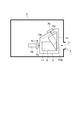
- FIG. 2 is a perspective view showing an imaging unit in a state in which a prism unit is inserted into the housing part of FIG. 1.
- FIG. 6 is a cross-sectional view taken along line VI-VI of the imaging unit in FIG. 5.
- It is sectional drawing along the VII-VII line of the imaging unit of FIG.
- It is a top view for demonstrating the positional relationship of each part in the imaging unit of FIG.
- It is a perspective view which shows the imaging unit which is 2nd Embodiment of this invention.
- FIG. It is a top view of the imaging unit of FIG. It is sectional drawing along the XI-XI line of the imaging unit of FIG. It is a perspective view which shows the imaging unit which is 2nd Embodiment of this invention. It is a top view of the imaging unit of FIG. It is sectional drawing along the XIV-XIV line of the imaging unit of FIG. It is sectional drawing of the imaging unit which is a modification of this invention. It is sectional drawing of the imaging unit which is another modification of this invention. It is sectional drawing of the imaging unit which is another modification of this invention. It is a perspective view which shows the imaging unit which is another modification of this invention. It is a top view of the prism unit of FIG. It is a top view of the imaging unit of FIG. It is sectional drawing along the XXI-XXI line of the imaging unit of FIG.
- FIG. 1 is a schematic configuration diagram of an imaging unit 1 according to the first embodiment of the present invention.
- the imaging unit 1 is an apparatus that spectrally captures measurement light such as fluorescence of the sample A to be observed connected to the microscope apparatus 101 and connected by the microscope apparatus 101.
- the microscope apparatus 101 to be connected for example, a structure in which measurement light (for example, fluorescence) emitted from the sample A disposed therein is emitted from the output port 107 via the microscope optical system 103 and the reflecting mirror 105. Is used.
- the imaging unit 1 is connected to the output port 107 of the microscope apparatus 101 and has a housing part 3 having an incident window 2 through which measurement light is incident, and a prism unit (prism) detachably housed in the housing part 3. Holding member) 5 and two image pickup elements 7a and 7b built in the casing 3 so as to face the prism unit 5.
- the prism unit 5 has a prism case 13A having a trapezoidal cross section, and two prisms 9a and 9b are held inside the prism case 13A. These two prisms 9a and 9b are joined together to form a color separation prism 9.
- the optical element held in the prism case 13A is not limited to the color separation prism, but is a polarization prism that separates the direction in which the measurement light travels by polarization, or a split prism that simply separates the direction in which the measurement light travels without color separation. There may be.
- a circular incident hole 15a and emission holes 15b and 15c are provided at positions facing the light incident surface 11a and the light emission surfaces 11b and 11c of the prisms 9a and 9b on the side surface of the prism case 13A.
- the size of the incident hole 15 is determined by the light beam incident from the imaging lens of the microscope optical system 103 of the microscope apparatus 101 and the light receiving area of the imaging elements 7a and 7b, and is large enough not to block the light beam through the incident hole 15. ing. As a result, it is possible to make the measurement light accurately enter the prism 9 and make it difficult for the disturbance light to enter the prism 9.
- the shapes of the entrance hole 15a and the exit holes 15b and 15c are determined by the shape of the light receiving surfaces of the image sensors 7a and 7b and the microscope optical system 103, and are not limited to a circle but may be a polygon such as a triangle or a rectangle.
- the Prism unit 5 having the above configuration, a portion of the wavelength range L 2 of the fluorescence L 1 in a predetermined wavelength range that is incident along the center axis of the entrance aperture 15a, along the central axis of the incident hole 15a
- the light passes through the prism 9 and is emitted from the light exit surface 11b to the outside through the exit hole 15b.
- the centers of the entrance hole 15a and the exit hole 15b are located on the coaxial optical path, and the radius of the exit hole 15b is the same as the radius of the entrance hole 15a, or the radius of the exit hole 15b is larger than the radius of the entrance hole 15a. small.
- the size of the light beam of the fluorescence L 2 when passing through the exit aperture 15b is compared with the size of the light beam of the fluorescence L 1 when passing through the entrance aperture 15a, comparable or smaller. Therefore, by reducing the size of the exit aperture 15b so as not to shield the fluorescence L 2, it is possible to prevent the disturbance light is incident on the image sensor 7a.
- the prism unit 5 the other portion of the wavelength range L 3 of its fluorescence L 1, prism 9a, is reflected by the bonding surface and the light incident surface 11a of 9b, the light emitting surface of the prism 9 After passing through 11c, the light is emitted to the outside through the emission hole 15c.
- the center of the exit hole 15c is located on the optical axis of the light beam of the fluorescence L 3 emitted from the light emitting surface 11c, the radius as large as the radius of the exit aperture 15c is incident hole 15a, or exit aperture 15c Is smaller than the radius of the incident hole 15a.
- the size of the light beam of the fluorescence L 3 when passing through the exit aperture 15c is also compared with the size of the light beam of the fluorescence L 1 when passing through the entrance aperture 15a, comparable or smaller. Therefore, by reducing the size of the exit aperture 15c so as not to shield the fluorescence L 3, it is possible to prevent the disturbance light is incident on the image sensor 7b.
- Such prism 9 has a role of dispersing the fluorescence L 1 in different directions, the spectral characteristics (spectral wavelength characteristics and emission angle), prism 9a, is determined by the material and shape of 9b.
- the area of the emission holes 15b and 15c may be equal to or smaller than the area of the incident hole 15a.
- a flange portion 13B is integrally formed at the upper end portion of the prism case 13A of the prism unit 5 along a direction substantially perpendicular to the side surface of the prism case 13A.
- the flange portion 13B extends vertically from the side surface of the prism case 13A in four directions, and the surface 17a on the opposite side to the prism case 13A and the surface 17b on the opposite side are substantially vertical flat surfaces.
- At the edge of the flange portion 13B there are two through holes 19a and 19b that penetrate from the surface 17a to the surface 17b on the opposite side, and two holes 21a and 21b that are recessed toward the surface 17a on the surface 17b. Is formed.
- the prism case 13A and the flange portion 13B are not limited to being formed integrally, but may be configured differently to form a prism unit by combining them.
- the prism unit 5 is detachably inserted into the housing unit 3 with the prism 9 built-in. As a result, the prism can be exchanged according to the wavelength range to be measured.
- 4 is a perspective view showing the imaging unit 1 in a state in which the prism unit 5 is inserted into the housing unit 3
- FIG. 5 is a plan view of the imaging unit 1 in FIG. 4
- FIG. 6 is an imaging unit 1 in FIG.
- FIG. 7 is a cross-sectional view taken along line VII-VII of the imaging unit 1 of FIG.
- the housing portion 3 is formed with a prism insertion portion 23 for inserting the prism unit 5, and the prism unit 5 extends along the side surface of the prism case 13 ⁇ / b> A along the prism insertion portion 23.
- the prism case 13A is inserted into the prism insertion part 23 from the end face 5a side opposite to the flange part 13B.
- the prism insertion portion 23 has a two-stage structure having an upper step portion (step portion) 23A and a lower step portion 23B so as to correspond to the outer shape of the prism unit 5.
- the width of the upper step portion 23A and the lower step portion 23B is slightly wider than the width of the flange portion 13B and the prism case 13A, and the depth of the lower step portion 23B is slightly deeper than the height of the prism case 13A.
- the flange portion 13B and the prism case 13A are accommodated in the upper step portion 23A and the lower step portion 23B, respectively, with a gap in the outer periphery thereof.
- the surface 17b of the flange portion 13B on the prism case 13A side comes into contact with the bottom surface of the upper step portion 23A, and the prism unit 5 is positioned in the insertion direction (the depth direction of the prism insertion portion 23).
- the flange portion 13B and the upper step portion 23A of the prism insertion portion 23 are formed so as to correspond to the outer shape of the prism unit 5, the flange portion 13B comes into contact with the upper step portion 23A of the prism insertion portion 23, so The portion 13B serves as a lid, and can prevent light from the outside from leaking into the housing. Thereby, light can be easily shielded by simply inserting the prism unit 5 into the prism insertion portion 23. Further, a gap is also formed between the end surface 5a of the prism case 13A and the bottom surface 33 of the lower step portion 23B.
- pins (projections) 25a and 25b are respectively embedded and fixed at positions facing the holes 21a and 21b of the flange portion 13B on the bottom surface of the upper step portion 23A, and the holes of the flange portion 13B.
- the prism unit 5 is positioned in a direction perpendicular to the insertion direction (a direction along the bottom surface of the prism insertion portion 23) (FIG. 6).
- the hole portion 21a of the flange portion 13B has a circular shape with substantially the same radius as the opposing pin 25a, but the hole portion 21b has a minor axis that is the same size as the radius of the opposing pin 25b and larger than that.
- a pin protruding portion
- a hole portion may be provided in the prism insertion portion 23.
- fixing screws (fixing members) 27a and 27b are provided between the flange portion 13B and the upper step portion 23A. These fixing screws 27a and 27b pass through the through holes 19a and 19b, and are fixed by being screwed into screw holes formed in the bottom surface of the upper step portion 23A of the housing portion 3, so that the prism unit 5 is positioned at the prism insertion portion. It has a role to stabilize in the 23.
- an information transmission unit 31A and an information reading unit 31B are attached to the bottom surface (outer surface) 5a of the prism case 13A and the bottom surface (inner surface) 33 of the lower step portion 23B, respectively.
- This information transmission unit 31A has a function for transmitting information related to the type of the prism 9 in the prism unit 5 to the housing unit 3 side in accordance with the insertion of the prism unit 5 into the prism insertion unit 23.
- An IC tag that transmits various information in a non-contact manner is used.
- the information reading unit 31B has a function of reading identification information from the information transmitting unit 31A, and an information reading device such as an IC tag reader / writer is used.
- the prism unit 5 is easily positioned in the insertion direction and the direction perpendicular to the insertion direction simply by being inserted into the prism insertion portion 23 due to the structure of the flange portion 13B.
- the prism unit 5 is disposed so that the incident hole 15 a faces the incident window 2 of the housing portion 3, and the prism unit 5 further has the light emitting holes 15 b and 15 c of the light emitting window of the housing portion 3. It arrange
- an image sensor 7 a that receives the measurement light L 2 in the long wavelength region and an image sensor 7 b that receives the measurement light L 3 in the short wavelength region are arranged so that the light receiving surfaces face the respective emission windows of the housing 3.
- the image pickup device 7 a is supported by the moving mechanism 29, and is movable by the moving mechanism 29 along the optical axis of the measurement light L 2 that passes through the prism 9.
- the prism 9 and the imaging elements 7a and 7b may be configured such that the imaging element 7b receives a long wavelength region and the imaging element 7a receives a short wavelength region.
- the image sensors 7a and 7b are arranged so that the longitudinal direction of the light receiving surface substantially coincides with the insertion direction.
- the size of the housing 3 can be made compact.
- the measurement lights L 2 and L 3 are imaged on the entire light receiving surfaces of the image sensor 7 a and the image sensor 7 b, but only a part of the pixel area is used for imaging as an imaging pixel area.
- the measurement range can be stabilized even if the positioning accuracy of the surfaces perpendicular to the optical axis of the image sensor 7a and the image sensor 7b is insufficient.
- the moving mechanism 29 supports the image sensor 7 a that receives the measurement light L 2 that is transmitted without being reflected in the prism 9.
- the housing of the microscope apparatus 101 protrudes in a plane direction perpendicular to the optical axis of the measurement light L 1 from the output port 107 of the microscope apparatus 101. Accordingly, when considering the connection between the imaging unit 1 and the output port 107 of the microscope apparatus 101, it is preferable not to enlarge the casing 3 of the imaging unit 1 in the plane direction of the incident window 2, and thus the imaging element 7a is moved by the moving mechanism 29. Is supported by.
- elements, such as CCD and CMOS are used as image pick-up element 7a, 7b, the cooling CCD suitable for weak light measurement is used suitably.
- the moving mechanism 29 a drive stage or a manual stage using a linear motor, a stepping motor, a piezo motor, or the like is used.
- the imaging unit 1 described above even when the prism 9 is replaced by detachably inserting the prism unit 5 holding the prism 9 into the prism insertion portion 23 formed in the housing 3, At the same time that the prism 9 is positioned inside the housing 3, the measurement light dispersed by the prism 9 is received by the two image sensors 7 a and 7 b provided inside the housing 3. Thereby, when it is going to replace the prism 9 according to the wavelength range to measure, the prism 9 corresponding to the wavelength range can be replaced
- the prism unit 5 is formed with a flange portion 13B extending substantially perpendicular to the insertion direction with respect to the prism insertion portion 23, and the flange portion 13B comes into contact with the prism insertion portion 23 so that the prism unit 5 moves in the insertion direction. Positioned.
- the prism unit 5 can be easily positioned in the insertion direction while providing a gap between the prism unit 5 and the prism insertion portion 23.
- the prism unit 5 can be smoothly inserted into the casing 3 and a slight processing error can be allowed.
- the flange portion 13B can prevent light from the outside of the housing 3 from entering the inside of the housing 3, and noise can be reduced.
- the information transmission unit 31A and the information reading unit 31B can be attached to the prism unit 5 and the prism insertion unit 23, respectively. If the prism 9 is replaced and used, generally, the range formed on the light receiving surfaces of the image sensors 7a and 7b tends to change according to the measurement lights L 2 and L 3 that are split by the prism 9. . Even in this case, since the type information of the prism 9 is transmitted from the information transmitting unit 31A to the information reading unit 31B, the prism 9 is used in the image processing unit or the like connected to the imaging elements 7a and 7b in the housing unit 3. Necessary pixel signals can be appropriately taken out and processed immediately after insertion.
- the identification information transmitted by the information transmission unit 31A includes information indicating “position information of the four corners” and “information regarding the position and range” of the imaging range in the image sensors 7a and 7b.
- the flange portion 13B of the prism unit 5 is provided with holes 21a and 21b, and the prism insertion portion 23 is provided with pins 25a and 25b, whereby the prism unit 5 is positioned in a direction perpendicular to the insertion direction.
- FIG. 9 is a perspective view showing an imaging unit 51 according to the second embodiment of the present invention
- FIG. 10 is a plan view of the imaging unit 51 in FIG. 9
- FIG. 11 is a XI-XI line of the imaging unit 51 in FIG. FIG.
- the main difference between the imaging unit 51 and the first embodiment is that the flange portion 63B of the prism unit 55 is formed on the opposite side to the insertion direction.
- the prism unit 55 has a prism case 63A having a trapezoidal cross-sectional shape, and the prism 9 is held inside the prism case 63A.
- a circular incident hole 65a and two emission holes are provided on the side surface of the prism case 63A.
- a flange portion 63B is integrally formed at the lower end portion of the prism case 13A of the prism unit 55 along a direction substantially perpendicular to the side surface of the prism case 63A.
- the flange portion 63B has a substantially flat surface 67a opposite to the prism case 63A.
- two through-holes 69a and 69b and two hole parts 71a and 71b are formed in the edge part of the surface 67a of the flange part 13B.
- a prism insertion portion 73 for inserting the prism unit 55 is formed in the housing portion 53, and the prism unit 55 has a flange so that the side surface of the flange portion 63 ⁇ / b> B is along the inner surface of the prism insertion portion 73. It is inserted into the prism insertion portion 73 from the surface 67a side of the portion 63B.
- the prism insertion portion 73 has a shape corresponding to the outer shape of the prism unit 55, the depth thereof is substantially the same as the height of the prism unit 55, and the width thereof is slightly larger than the width of the flange portion 63B.
- the flange portion 63B is accommodated in the prism insertion portion 73 with a gap in the outer periphery thereof. Then, the surface 67a of the flange portion 13B comes into contact with the bottom surface 83 of the prism insertion portion 73, and the prism unit 55 is positioned in the insertion direction (the depth direction of the prism insertion portion 73).
- pins 75a and 75b are embedded and fixed at positions facing the holes 71a and 71b of the flange part 63B on the bottom surface 83 of the prism insertion part 73, respectively, and the holes 71a and 71b of the flange part 63B are fixed.
- the prism unit 55 is positioned in the direction perpendicular to the insertion direction (the direction along the bottom surface 83 of the prism insertion portion 73) (FIG. 11). Further, the flange portion 63B and the prism insertion portion 73 are fixed by fixing screws 77a and 77b. As a result, the prism unit 55 is positioned and fixed two-dimensionally inside the housing portion 53 together with the prism 9.
- an information transmission portion 81A and an information reading portion 81B are attached in order to transmit identification information regarding the prism 9.
- the prism unit 55 corresponding to the wavelength range can be replaced smoothly. Furthermore, even when the prism unit 55 is replaced, the position of the prism 9 can be two-dimensionally stabilized with respect to the imaging elements 7a and 7b, so that stable imaging with respect to the measurement range of the sample A is realized.
- FIG. 12 is a perspective view showing an imaging unit 201 according to the third embodiment of the present invention
- FIG. 13 is a plan view of the imaging unit 201 in FIG. 12
- FIG. 14 is an XIV-XIV line of the imaging unit 201 in FIG. FIG.
- the main difference of the imaging unit 201 from the first embodiment is that a fixing lever (spring member) 203 is provided in the housing unit 3 as a positioning mechanism of the prism unit 5.
- a fixing lever 203 that urges the prism unit 5 in a direction perpendicular to the insertion direction when the prism unit 5 is inserted is attached to the upper stage portion 23A of the prism insertion portion 23 of the housing unit 3. It has been.
- the fixing lever 203 is fitted on the edge of the upper step portion 23A so as to be slidable in one direction along the bottom surface of the upper step portion 23A, and is inserted between the fixing lever 203 and the outer peripheral surface of the upper step portion 23A.
- the spring member 207 is biased toward the central portion along the bottom surface of the upper step portion 23A.
- protrusions 209a, 209b, and 209c for sandwiching the flange portion 13B together with the fixing lever 203 are embedded in the edge portion of the bottom surface of the upper step portion 23A so as to surround the center portion of the upper step portion 23A.
- the prism unit 5 When the prism unit 5 is inserted into the casing 3 having such a configuration with the fixing lever 203 slid to the edge of the upper step portion 23A, the edge of the flange portion 13B and the inner peripheral surface of the upper step portion 23A. Since the fixing lever 203 is interposed between the flange portion 13B and the flange portion 13B, the flange portion 13B is stored in the upper step portion 23A in a state of being pressed in a direction perpendicular to the insertion direction.
- the surface 17b of the flange portion 13B on the prism case 13A side comes into contact with the bottom surface of the upper step portion 23A, and the edge portion of the flange portion 13B is sandwiched between the fixing lever 203 and the projecting portions 209a, 209b, and 209c.
- 5 is positioned in the insertion direction and in a direction perpendicular to the insertion direction (FIG. 14).
- the prism unit 5 is positioned two-dimensionally inside the housing unit 3 together with the prism 9 in a state where the side surface and the bottom surface of the prism case 13A are separated from the prism insertion unit 23.
- the imaging unit 201 may be provided with a fixing screw 27a, an information transmission unit 81A, and an information reading unit 81B.
- the prism unit 55 corresponding to the wavelength range to be measured can be replaced smoothly, and stable imaging with respect to the sample A measurement range is realized.
- the insertion direction of the prism unit with respect to the casing is not limited to a specific direction.
- the prism insertion portion 273 is formed along a plane including the optical axis of the measurement light L 1 to the housing 253.
- the prism insertion portion 273 has a two-stage structure of an upper step portion 273A and a lower step portion 273B formed from the side surface of the housing portion 253 toward the inside, and a prism constituted by a prism case 263A and a flange portion 263B.
- the unit 255, along a plane including the optical axis of the measurement light L 1 may be inserted from the side of the casing 253.
- the positioning structure of the prism unit with respect to the casing can take various modifications.
- the flange portion 313B of the prism unit 305 is formed so that the side surface thereof is linearly inclined toward the prism case 13A, and the inner periphery of the upper step portion 323A of the prism insertion portion 323 is formed.
- the surface is formed so as to be inclined corresponding to the shape and width of the flange portion 313B.
- countersunk screws 377a and 377b may be used as members for positioning and fixing the prism unit 5 with respect to the casing 3 as in the imaging unit 351 shown in FIG.
- through holes 369a and 369b penetrating from the outer surface 17a toward the inner surface 17b are formed at the edge of the flange portion 13B of the prism unit 5, and these through holes 369a and 369b are countersunk screws 377a,
- the inner diameter is formed so as to decrease from the outer surface 17a to the inner surface 17b so as to correspond to the head shape of 377b.
- a combination of an elastic member and a fitting structure of the protruding portion and the hole portion may be employed. Good.
- the hole 21b is formed in a substantially elliptical shape having a long axis substantially parallel to a line connecting the center of the hole 21a and the center of the hole 21b. Furthermore, two through-holes 19a and 19b penetrating from the surface 17a to the surface 17b are formed at the edge of the flange portion 13B.
- the pins 25a and 25b are respectively located at positions facing the holes 21a and 21b on the bottom surface of the upper step portion 23A of the prism insertion portion 23 in a state where the prism unit 5 is inserted into the housing portion 3. Is embedded and fixed.
- the pin 25a has a substantially cylindrical shape with substantially the same radius as the opposing hole 21a
- the pin 25b has a substantially cylindrical shape with a radius substantially the same as the short diameter of the opposing hole 21b. is doing.
- an elastic pin (spring member) 403 is provided on the inner wall surface of the upper step portion 23A of the prism insertion portion 23 so as to protrude toward the corner opposite to the corner where the hole portion 21b of the flange portion 13B is provided. ing.
- the elastic pin 403 includes an elastic member such as a spring member inside, and is inserted so as to be positioned in a gap between the flange portion 13B and the prism insertion portion 23, and the prism unit 5 is inserted into the prism insertion portion 23. It has a role of energizing in the direction from the hole 21a toward the hole 21b along the bottom surface of the upper stage 23A.
- the pins 25a and 25b are fitted into the holes 21a and 21b of the flange portion 13B, and at the same time, the flange portion 13B. Is urged by the elastic pin 403 to move away from the elastic pin 403 along the bottom surface of the upper step portion 23A of the prism insertion portion 23 with the hole 21a as a fulcrum with respect to the prism unit 5 (indicated by the arrow in FIG. Direction) is applied.
- the hole portion 21b of the flange portion 13B and the pin 25b come into contact with each other and the mutual positional relationship is stabilized, so that the prism unit 5 can be securely inserted in a direction perpendicular to the insertion direction into the housing portion 3. Positioned.
- the prism holding member is formed with a flange portion extending substantially perpendicular to the insertion direction with respect to the prism insertion portion, and the prism holding member is positioned in the insertion direction by contacting the flange insertion portion with the prism insertion portion.
- the prism insertion portion has a surface that contacts the edge of the flange portion, and the prism holding member is positioned in the insertion direction when the edge of the flange portion contacts the surface. is there.
- the prism holding member can be easily positioned in the insertion direction even if a gap is provided between the prism holding member and the prism insertion portion.
- the prism holding member can be smoothly inserted into the housing, and some processing errors can be allowed.
- “extends substantially vertically” is a concept including a case where any surface of the member forms a substantially vertical surface.
- the flange portion of the prism holding member is provided with a protrusion or a hole
- the prism insertion portion is provided with a hole or a protrusion corresponding to the prism holding member. It is also preferable that the prism holding member is positioned in a direction perpendicular to the insertion direction by fitting the portion into the hole or the protruding portion of the prism insertion portion. With such a configuration, when the prism holding member is inserted into the prism insertion portion, the prism can be easily positioned in a direction perpendicular to the insertion direction.
- the prism insertion portion is formed with a step portion that fits into the flange portion, and the prism holding member is positioned in a direction perpendicular to the insertion direction by fitting the flange portion into the step portion. It is. With such a step portion, when the prism holding member is inserted into the prism insertion portion, the prism can be easily positioned in a direction perpendicular to the insertion direction. In addition, the positioning mechanism can be relatively simplified.
- a fixing member for fixing the prism holding member to the prism insertion portion is provided between the flange portion and the prism insertion portion.
- the fixing member may be a screw member that penetrates the flange portion toward the prism insertion portion, or is inserted into a gap between the flange portion and the prism insertion portion, and the flange portion is substantially perpendicular to the insertion direction. It may be a spring member that biases in any direction.
- a gap portion is formed between the outer surface of the prism holding member and the inner surface of the prism insertion portion, and an information transmitting portion is provided on the outer surface of the prism holding member in contact with the gap portion. It is also preferable that an information reading unit is provided on the inner surface of the prism insertion unit in contact therewith.
- the present invention uses an imaging unit, allows a prism to be smoothly exchanged, and stabilizes the measurement range.
Abstract
An image-capturing unit configured so that the prism can be smoothly interchanged and that the range of measurement can be stabilized. An image-capturing unit (1) is provided with: a prism unit (5) in which a prism (9) is held; a housing (3) provided with a prism insertion section (23), in which the prism unit (5) can be removably inserted, and allowing measurement light to enter the housing (3) from the outside; and two image-capturing elements (7a, 7b) incorporated in the housing (3). The prism insertion section (23) is formed in such a manner that, when the prism unit (5) is inserted therein, the prism insertion section (23) positions the prism unit (5) to a position within the housing (3) together with the prism (9). The image-capturing elements (7a, 7b) are respectively provided at positions which can receive the measurement light dispersed by the prism (9).
Description
本発明は、外部からの測定光を撮像する撮像ユニットに関するものである。
The present invention relates to an imaging unit that images measurement light from the outside.
近年、生細胞を対象にした顕微鏡ライブイメージングは、カルシウムイオンをはじめとする細胞内の情報伝達機構の解明に不可欠な研究手段となっている。最近では、その研究手段が、複数の機能細胞間の相互作用やシグナル情報など、より多くの情報を同時に取得する方法へと発展しつつある。また、培養細胞のみならずより生体に近い組織レベルでの機能研究が盛んに行われている。特に、(i)異なる波長の蛍光を同時に観察する、(ii)2波長蛍光のレシオイメージングを行う、(iii)FRET(Fluorescence Resonance Energy Transfer)等によって発生する異なる2波長の蛍光を同時にイメージングする等により、細胞内の情報伝達機構を解明する研究が広く行われている。
In recent years, live microscopic imaging of living cells has become an indispensable research tool for elucidation of intracellular signal transduction mechanisms including calcium ions. Recently, the research means has been developed into a method for simultaneously acquiring more information such as interaction between a plurality of functional cells and signal information. Moreover, functional research not only in cultured cells but also at a tissue level closer to a living body has been actively conducted. In particular, (i) observing fluorescence of different wavelengths at the same time, (ii) performing ratio imaging of two-wavelength fluorescence, (iii) simultaneously imaging fluorescence of two different wavelengths generated by FRET (Fluorescence Resonance Energy Transfer), etc. Therefore, research to elucidate the intracellular information transmission mechanism has been widely conducted.
上述したような研究において異なる波長の光を撮像する際には、色分解光学系としてプリズムが用いられ、既存の顕微鏡で観察された測定光をプリズムによって分光して撮像する必要がある。このプリズムを備える従来の撮像装置としては、下記特許文献1,2のものが知られている。下記特許文献1に記載の撮像装置は、プリズム及び接合用突起を有するプリズムブロックと、固体撮像素子を有する撮像ブロックとが接合された構造を有し、プリズムブロックが撮像ブロックと接合された後でもプリズムを取り外し可能な構成を有している。また、下記特許文献2に記載の撮像装置は、プリズムを保持するプリズムケースを撮像レンズ系の筐体後部プレートに常時押圧するように構成されている。
When imaging light of different wavelengths in the research as described above, a prism is used as a color separation optical system, and it is necessary to spectrally image the measurement light observed with an existing microscope and image it. As conventional imaging devices including this prism, those disclosed in Patent Documents 1 and 2 below are known. The imaging device described in the following Patent Document 1 has a structure in which a prism block having a prism and a joining projection and an imaging block having a solid-state imaging device are joined, and even after the prism block is joined to the imaging block. The prism can be removed. Further, the imaging device described in Patent Document 2 is configured to always press a prism case that holds a prism against a housing rear plate of an imaging lens system.
しかしながら、上述した特許文献1,2記載の撮像装置では、測定対象の波長域に応じてプリズムを交換しようとした際に、プリズムの交換作業が効率的でなく、プリズムの位置決め機構が不十分であり、測定範囲の安定したイメージングが困難な傾向にあった。
However, in the imaging devices described in Patent Documents 1 and 2 described above, when the prism is to be replaced according to the wavelength range to be measured, the prism replacement operation is not efficient and the prism positioning mechanism is insufficient. There was a tendency that imaging with a stable measurement range was difficult.
そこで、本発明は、かかる課題に鑑みて為されたものであり、プリズムの円滑な交換を可能にし、かつ、測定範囲の安定化を可能にする撮像ユニットを提供することを目的とする。
Therefore, the present invention has been made in view of such a problem, and an object of the present invention is to provide an imaging unit that allows a prism to be smoothly exchanged and a measurement range to be stabilized.
上記課題を解決するため、本発明の撮像ユニットは、プリズムを内部に保持するプリズム保持部材と、プリズム保持部材が着脱可能にされるプリズム挿入部が形成され、外部から測定光が入射される筐体部と、筐体部に内蔵された2以上の撮像素子と、を備え、プリズム挿入部は、プリズム保持部材が挿入された際に、プリズムと共にプリズム保持部材を筐体部の内部に位置決めするように形成され、2以上の撮像素子は、プリズムによって分けられた測定光を、受光可能な位置にそれぞれ設けられている。
In order to solve the above-described problems, an imaging unit according to the present invention includes a prism holding member that holds a prism inside, and a prism insertion portion that allows the prism holding member to be attached and detached. And a prism insertion unit that positions the prism holding member together with the prism inside the casing when the prism holding member is inserted. Thus, the two or more image sensors are respectively provided at positions where the measurement light divided by the prism can be received.
このような撮像ユニットによれば、プリズムを保持するプリズム保持部材が、筐体部に形成されたプリズム挿入部に着脱自在に挿入されることにより、プリズムが筐体部の内部で位置決めされると同時に、筐体部内部に設けられた2以上の撮像素子によってプリズムで分けられた測定光が受光される。これにより、測定光の波長域に対応してプリズムを円滑に交換することができるとともに、プリズムを交換した際でも撮像素子によって測定範囲に対する安定したイメージングが実現される。
According to such an imaging unit, the prism holding member that holds the prism is detachably inserted into the prism insertion portion formed in the housing portion, so that the prism is positioned inside the housing portion. At the same time, the measurement light divided by the prism is received by two or more imaging elements provided inside the housing. Thus, the prism can be smoothly exchanged corresponding to the wavelength range of the measurement light, and stable imaging with respect to the measurement range is realized by the imaging device even when the prism is exchanged.
本発明によれば、プリズムの円滑な交換が可能にされ、かつ、測定範囲の安定化が可能にされる。
According to the present invention, the prism can be smoothly exchanged and the measurement range can be stabilized.
以下、図面を参照しつつ本発明に係る撮像ユニットの好適な実施形態について詳細に説明する。なお、図面の説明においては同一又は相当部分には同一符号を付し、重複する説明を省略する。
Hereinafter, preferred embodiments of an imaging unit according to the present invention will be described in detail with reference to the drawings. In the description of the drawings, the same or corresponding parts are denoted by the same reference numerals, and redundant description is omitted.
(第1実施形態)
図1は、本発明の第1実施形態に係る撮像ユニット1の概略構成図である。同図に示すように、撮像ユニット1は、顕微鏡装置101に接続されて顕微鏡装置101によって結ばれた観察対象の試料Aの蛍光等の測定光を分光して撮像する装置である。接続対象の顕微鏡装置101としては、例えば、内部に配置された試料Aから発せられる測定光(例えば、蛍光)を、顕微鏡光学系103及び反射鏡105を介して出力ポート107から出射するような構造のものが使用される。この撮像ユニット1は、顕微鏡装置101の出力ポート107に接続されて測定光が入射される入射窓2を有する筐体部3と、その筐体部3に着脱自在に収納されるプリズムユニット(プリズム保持部材)5と、筐体部3内でプリズムユニット5と対向するように内蔵された2つの撮像素子7a,7bとを備える。 (First embodiment)
FIG. 1 is a schematic configuration diagram of animaging unit 1 according to the first embodiment of the present invention. As shown in FIG. 1, the imaging unit 1 is an apparatus that spectrally captures measurement light such as fluorescence of the sample A to be observed connected to the microscope apparatus 101 and connected by the microscope apparatus 101. As the microscope apparatus 101 to be connected, for example, a structure in which measurement light (for example, fluorescence) emitted from the sample A disposed therein is emitted from the output port 107 via the microscope optical system 103 and the reflecting mirror 105. Is used. The imaging unit 1 is connected to the output port 107 of the microscope apparatus 101 and has a housing part 3 having an incident window 2 through which measurement light is incident, and a prism unit (prism) detachably housed in the housing part 3. Holding member) 5 and two image pickup elements 7a and 7b built in the casing 3 so as to face the prism unit 5.
図1は、本発明の第1実施形態に係る撮像ユニット1の概略構成図である。同図に示すように、撮像ユニット1は、顕微鏡装置101に接続されて顕微鏡装置101によって結ばれた観察対象の試料Aの蛍光等の測定光を分光して撮像する装置である。接続対象の顕微鏡装置101としては、例えば、内部に配置された試料Aから発せられる測定光(例えば、蛍光)を、顕微鏡光学系103及び反射鏡105を介して出力ポート107から出射するような構造のものが使用される。この撮像ユニット1は、顕微鏡装置101の出力ポート107に接続されて測定光が入射される入射窓2を有する筐体部3と、その筐体部3に着脱自在に収納されるプリズムユニット(プリズム保持部材)5と、筐体部3内でプリズムユニット5と対向するように内蔵された2つの撮像素子7a,7bとを備える。 (First embodiment)
FIG. 1 is a schematic configuration diagram of an
図2及び図3に示すように、プリズムユニット5は、断面台形状の外形をなすプリズムケース13Aを有し、このプリズムケース13Aの内部には2つのプリズム9a,9bが保持されている。これらの2つのプリズム9a,9bは、互いに接合されて色分解プリズム9を構成している。なお、プリズムケース13Aに保持される光学素子は色分解プリズムに限らず、偏光によって測定光の進む方向を分離する偏光プリズムや、色分解せずに単に測定光の進む方向を分離する分割プリズムであってもよい。そして、プリズムケース13Aの側面におけるプリズム9a,9bの光入射面11a及び光出射面11b,11cのそれぞれに対向する位置には、円形の入射孔15a及び出射孔15b,15cが設けられている。入射孔15の大きさは、顕微鏡装置101の顕微鏡光学系103の結像レンズから入射される光束と撮像素子7a,7bの受光面積によってきまり、入射孔15で光束を遮光しない程度の大きさとなっている。これにより、測定光を正確にプリズム9に入射させ、かつ外乱光をプリズム9に入射させにくくすることができる。なお、入射孔15a及び出射孔15b,15cの形状は、撮像素子7a,7bの受光面の形状や顕微鏡光学系103によって決まり、円形に限らず三角形や四角形などの多角形であってもよい。
2 and 3, the prism unit 5 has a prism case 13A having a trapezoidal cross section, and two prisms 9a and 9b are held inside the prism case 13A. These two prisms 9a and 9b are joined together to form a color separation prism 9. The optical element held in the prism case 13A is not limited to the color separation prism, but is a polarization prism that separates the direction in which the measurement light travels by polarization, or a split prism that simply separates the direction in which the measurement light travels without color separation. There may be. A circular incident hole 15a and emission holes 15b and 15c are provided at positions facing the light incident surface 11a and the light emission surfaces 11b and 11c of the prisms 9a and 9b on the side surface of the prism case 13A. The size of the incident hole 15 is determined by the light beam incident from the imaging lens of the microscope optical system 103 of the microscope apparatus 101 and the light receiving area of the imaging elements 7a and 7b, and is large enough not to block the light beam through the incident hole 15. ing. As a result, it is possible to make the measurement light accurately enter the prism 9 and make it difficult for the disturbance light to enter the prism 9. The shapes of the entrance hole 15a and the exit holes 15b and 15c are determined by the shape of the light receiving surfaces of the image sensors 7a and 7b and the microscope optical system 103, and are not limited to a circle but may be a polygon such as a triangle or a rectangle.
上記のような構成のプリズムユニット5は、入射孔15aの中心軸線に沿って入射した所定波長域の蛍光L1のうちの一部の波長域L2を、入射孔15aの中心軸線に沿ってプリズム9を透過させて光出射面11bから出射孔15bを通じて外部に出射させる。ここで、入射孔15aと出射孔15bの中心は同軸光路上に位置し、出射孔15bの半径は入射孔15aの半径と同じ大きさ、もしくは出射孔15bの半径は入射孔15aの半径よりも小さい。一般的に、出射孔15bを通過する際の蛍光L2の光束の大きさは、入射孔15aを通過する際の蛍光L1の光束の大きさに比べ、同程度もしくは小さくなる。従って、出射孔15bの大きさを蛍光L2を遮光しない程度に小さくすることで、外乱光が撮像素子7aに入射されることを防ぐことができる。それと同時に、プリズムユニット5は、その蛍光L1のうちの他の一部の波長域L3を、プリズム9a,9bの接合面及び光入射面11aで反射させて、プリズム9内を光出射面11cまで透過させた後に、出射孔15cを通じて外部に出射させる。ここで、出射孔15cの中心は光出射面11cから出射される蛍光L3の光束の光軸上に位置し、出射孔15cの半径は入射孔15aの半径と同じ大きさ、もしくは出射孔15cの半径は入射孔15aの半径よりも小さい。一般的に、出射孔15cを通過する際の蛍光L3の光束の大きさもまた、入射孔15aを通過する際の蛍光L1の光束の大きさに比べ、同程度もしくは小さくなる。従って、出射孔15cの大きさを蛍光L3を遮光しない程度に小さくすることで、外乱光が撮像素子7bに入射されることを防ぐことができる。このようなプリズム9は、蛍光L1を異なる方向に分光する役割を有し、その分光特性(分光波長特性や出射角度)は、プリズム9a,9bの材料や形状によって決定される。また、入射孔15a及び出射孔15b,15cの形状が円形以外の場合、出射孔15b,15cの面積は入射孔15aの面積と同程度もしくはそれより小さければよい。
Prism unit 5 having the above configuration, a portion of the wavelength range L 2 of the fluorescence L 1 in a predetermined wavelength range that is incident along the center axis of the entrance aperture 15a, along the central axis of the incident hole 15a The light passes through the prism 9 and is emitted from the light exit surface 11b to the outside through the exit hole 15b. Here, the centers of the entrance hole 15a and the exit hole 15b are located on the coaxial optical path, and the radius of the exit hole 15b is the same as the radius of the entrance hole 15a, or the radius of the exit hole 15b is larger than the radius of the entrance hole 15a. small. In general, the size of the light beam of the fluorescence L 2 when passing through the exit aperture 15b is compared with the size of the light beam of the fluorescence L 1 when passing through the entrance aperture 15a, comparable or smaller. Therefore, by reducing the size of the exit aperture 15b so as not to shield the fluorescence L 2, it is possible to prevent the disturbance light is incident on the image sensor 7a. At the same time, the prism unit 5, the other portion of the wavelength range L 3 of its fluorescence L 1, prism 9a, is reflected by the bonding surface and the light incident surface 11a of 9b, the light emitting surface of the prism 9 After passing through 11c, the light is emitted to the outside through the emission hole 15c. Here, the center of the exit hole 15c is located on the optical axis of the light beam of the fluorescence L 3 emitted from the light emitting surface 11c, the radius as large as the radius of the exit aperture 15c is incident hole 15a, or exit aperture 15c Is smaller than the radius of the incident hole 15a. In general, the size of the light beam of the fluorescence L 3 when passing through the exit aperture 15c is also compared with the size of the light beam of the fluorescence L 1 when passing through the entrance aperture 15a, comparable or smaller. Therefore, by reducing the size of the exit aperture 15c so as not to shield the fluorescence L 3, it is possible to prevent the disturbance light is incident on the image sensor 7b. Such prism 9 has a role of dispersing the fluorescence L 1 in different directions, the spectral characteristics (spectral wavelength characteristics and emission angle), prism 9a, is determined by the material and shape of 9b. In addition, when the shapes of the incident hole 15a and the emission holes 15b and 15c are other than circular, the area of the emission holes 15b and 15c may be equal to or smaller than the area of the incident hole 15a.
さらに、プリズムユニット5のプリズムケース13Aの上端部には、プリズムケース13Aの側面に対して略垂直な方向に沿ってフランジ部13Bが一体的に形成されている。このフランジ部13Bはプリズムケース13Aの側面から垂直に四方に向けて伸びており、プリズムケース13Aと反対側の面17a及びその反対側の面17bは、ほぼ垂直な平坦面となっている。そして、フランジ部13Bの縁部には、面17aからその反対側の面17bにかけて貫通する2つの貫通孔19a,19b、及び面17b上で面17aに向けて凹む2つの孔部21a,21bが形成されている。なお、プリズムケース13Aとフランジ部13Bは一体的に形成されることに限らず、それぞれ別の構成とし、それらを組み合わせてプリズムユニットを形成してもよい。
Further, a flange portion 13B is integrally formed at the upper end portion of the prism case 13A of the prism unit 5 along a direction substantially perpendicular to the side surface of the prism case 13A. The flange portion 13B extends vertically from the side surface of the prism case 13A in four directions, and the surface 17a on the opposite side to the prism case 13A and the surface 17b on the opposite side are substantially vertical flat surfaces. At the edge of the flange portion 13B, there are two through holes 19a and 19b that penetrate from the surface 17a to the surface 17b on the opposite side, and two holes 21a and 21b that are recessed toward the surface 17a on the surface 17b. Is formed. Note that the prism case 13A and the flange portion 13B are not limited to being formed integrally, but may be configured differently to form a prism unit by combining them.
上記プリズムユニット5は、プリズム9を内蔵したままで筐体部3に着脱可能に挿入される。これにより、測定対象の波長域に応じてプリズムを交換することが可能となる。図4は、筐体部3にプリズムユニット5が挿入された状態の撮像ユニット1を示す斜視図、図5は、図4の撮像ユニット1の平面図、図6は、図5の撮像ユニット1のVI-VI線に沿った断面図、図7は、図5の撮像ユニット1のVII-VII線に沿った断面図である。
The prism unit 5 is detachably inserted into the housing unit 3 with the prism 9 built-in. As a result, the prism can be exchanged according to the wavelength range to be measured. 4 is a perspective view showing the imaging unit 1 in a state in which the prism unit 5 is inserted into the housing unit 3, FIG. 5 is a plan view of the imaging unit 1 in FIG. 4, and FIG. 6 is an imaging unit 1 in FIG. FIG. 7 is a cross-sectional view taken along line VII-VII of the imaging unit 1 of FIG.
これらの図に示すように、筐体部3には、プリズムユニット5を挿入するためのプリズム挿入部23が形成されており、プリズムユニット5は、プリズムケース13Aの側面をプリズム挿入部23に沿わせるように、プリズムケース13Aのフランジ部13Bに対して反対側の端面5a側からプリズム挿入部23に挿入される。このプリズム挿入部23は、プリズムユニット5の外形に対応するように、上段部(段差部)23Aと下段部23Bとを有する2段構造をなしている。ここで、上段部23A及び下段部23Bの幅は、フランジ部13B及びプリズムケース13Aの幅よりもやや広く、下段部23Bの深さは、プリズムケース13Aの高さよりもやや深くなっている。
As shown in these drawings, the housing portion 3 is formed with a prism insertion portion 23 for inserting the prism unit 5, and the prism unit 5 extends along the side surface of the prism case 13 </ b> A along the prism insertion portion 23. As shown, the prism case 13A is inserted into the prism insertion part 23 from the end face 5a side opposite to the flange part 13B. The prism insertion portion 23 has a two-stage structure having an upper step portion (step portion) 23A and a lower step portion 23B so as to correspond to the outer shape of the prism unit 5. Here, the width of the upper step portion 23A and the lower step portion 23B is slightly wider than the width of the flange portion 13B and the prism case 13A, and the depth of the lower step portion 23B is slightly deeper than the height of the prism case 13A.
プリズムユニット5がプリズム挿入部23に挿入された状態では、フランジ部13B及びプリズムケース13Aが、その外周部に隙間を空けた状態で上段部23A及び下段部23Bに、それぞれ収められる。このとき、フランジ部13Bのプリズムケース13A側の面17bが上段部23Aの底面に当接して、プリズムユニット5がその挿入方向(プリズム挿入部23の深さ方向)に位置決めされる。したがって、フランジ部13Bとプリズム挿入部23の上段部23Aはプリズムユニット5の外形に対応するように形成されているので、フランジ部13Bがプリズム挿入部23の上段部23Aに当接することで、プランジ部13Bがふたの役割をはたし、外部からの光が筐体内部に漏れないようにすることができる。これにより、プリズムユニット5をプリズム挿入部23に挿入するだけで、簡単に遮光することが可能となる。また、プリズムケース13Aの端面5aと下段部23Bの底面33との間にも間隙が形成される。併せて、上段部23Aの底面におけるフランジ部13Bの孔部21a,21bに対向する位置には、それぞれ、ピン(突出部)25a,25bが埋め込まれて固定されており、フランジ部13Bの孔部21a,21bにピン25a,25bが嵌め合わされることにより、プリズムユニット5がその挿入方向に対して垂直な方向(プリズム挿入部23の底面に沿った方向)に位置決めされる(図6)。ここで、フランジ部13Bの孔部21aは、対向するピン25aと略同半径の円形状であるが、孔部21bは、対向するピン25bの半径と同じ大きさの短径とそれよりも大きい長径を有する楕円形状となっている。これにより、フランジ部13Bの孔部21a,21bやピン25a,25bの位置精度が不十分の場合でも、嵌め合わせでき、かつ片方の孔部が楕円なので位置決めを確実に行うことができる。なお、このような位置決め構造に関しては、フランジ部13Bにピン(突出部)が、プリズム挿入部23に孔部が、それぞれ設けられてもよい。これにより、プリズムユニット5がプリズム9と共に筐体部3内部において2次元的に位置決めされる。
In a state where the prism unit 5 is inserted into the prism insertion portion 23, the flange portion 13B and the prism case 13A are accommodated in the upper step portion 23A and the lower step portion 23B, respectively, with a gap in the outer periphery thereof. At this time, the surface 17b of the flange portion 13B on the prism case 13A side comes into contact with the bottom surface of the upper step portion 23A, and the prism unit 5 is positioned in the insertion direction (the depth direction of the prism insertion portion 23). Accordingly, since the flange portion 13B and the upper step portion 23A of the prism insertion portion 23 are formed so as to correspond to the outer shape of the prism unit 5, the flange portion 13B comes into contact with the upper step portion 23A of the prism insertion portion 23, so The portion 13B serves as a lid, and can prevent light from the outside from leaking into the housing. Thereby, light can be easily shielded by simply inserting the prism unit 5 into the prism insertion portion 23. Further, a gap is also formed between the end surface 5a of the prism case 13A and the bottom surface 33 of the lower step portion 23B. In addition, pins (projections) 25a and 25b are respectively embedded and fixed at positions facing the holes 21a and 21b of the flange portion 13B on the bottom surface of the upper step portion 23A, and the holes of the flange portion 13B. By fitting the pins 25a and 25b to 21a and 21b, the prism unit 5 is positioned in a direction perpendicular to the insertion direction (a direction along the bottom surface of the prism insertion portion 23) (FIG. 6). Here, the hole portion 21a of the flange portion 13B has a circular shape with substantially the same radius as the opposing pin 25a, but the hole portion 21b has a minor axis that is the same size as the radius of the opposing pin 25b and larger than that. It has an elliptical shape with a major axis. Thereby, even when the positional accuracy of the holes 21a and 21b and the pins 25a and 25b of the flange portion 13B is insufficient, the fitting can be performed and positioning can be reliably performed because one of the holes is an ellipse. Regarding such a positioning structure, a pin (protruding portion) may be provided in the flange portion 13B, and a hole portion may be provided in the prism insertion portion 23. As a result, the prism unit 5 is positioned two-dimensionally inside the housing 3 together with the prism 9.
また、図7に示すように、フランジ部13Bと上段部23Aとの間には、固定ネジ(固定部材)27a,27bが設けられている。これらの固定ネジ27a,27bは、貫通孔19a,19bを貫通し、筐体部3の上段部23Aの底面に形成されたネジ穴にねじ込まれて固定され、プリズムユニット5の位置をプリズム挿入部23内で安定化するための役割を有する。
Further, as shown in FIG. 7, fixing screws (fixing members) 27a and 27b are provided between the flange portion 13B and the upper step portion 23A. These fixing screws 27a and 27b pass through the through holes 19a and 19b, and are fixed by being screwed into screw holes formed in the bottom surface of the upper step portion 23A of the housing portion 3, so that the prism unit 5 is positioned at the prism insertion portion. It has a role to stabilize in the 23.
さらに、図6に示すように、プリズムケース13Aの底面(外表面)5a、及び下段部23Bの底面(内表面)33には、それぞれ、情報送信部31A及び情報読取部31Bが取り付けられている。この情報送信部31Aは、プリズムユニット5のプリズム挿入部23への挿入に応じて、プリズムユニット5内のプリズム9の種別に関する情報を筐体部3側に伝達するための機能を有し、例えば、非接触で各種情報を送信するICタグ等が用いられる。また、情報読取部31Bは、情報送信部31Aからの識別情報を読み取る機能を有し、ICタグ用リーダ/ライタ等の情報読取装置が用いられる。また、プリズムケース13Aの底面(外表面)5a、及び下段部23Bの底面(内表面)33の間は間隙が形成されているので、情報送信部31A及び情報読取部31Bが接触する恐れを低減でき、情報送信部31A及び情報読取部31Bの破壊を防ぐことが可能となる。
Further, as shown in FIG. 6, an information transmission unit 31A and an information reading unit 31B are attached to the bottom surface (outer surface) 5a of the prism case 13A and the bottom surface (inner surface) 33 of the lower step portion 23B, respectively. . This information transmission unit 31A has a function for transmitting information related to the type of the prism 9 in the prism unit 5 to the housing unit 3 side in accordance with the insertion of the prism unit 5 into the prism insertion unit 23. An IC tag that transmits various information in a non-contact manner is used. The information reading unit 31B has a function of reading identification information from the information transmitting unit 31A, and an information reading device such as an IC tag reader / writer is used. In addition, since a gap is formed between the bottom surface (outer surface) 5a of the prism case 13A and the bottom surface (inner surface) 33 of the lower step portion 23B, the possibility that the information transmitting unit 31A and the information reading unit 31B come into contact with each other is reduced. It is possible to prevent destruction of the information transmitting unit 31A and the information reading unit 31B.
次に、図8を参照しながら、筐体部3内におけるプリズムユニット5と撮像素子7a,7bとの位置関係について説明する。同図に示すように、プリズムユニット5はそのフランジ部13Bの構造により、プリズム挿入部23に挿入するだけで容易に挿入方向ならびに挿入方向に対して垂直な方向に位置決めされる。このとき、プリズムユニット5は、その入射孔15aを筐体部3の入射窓2に対向させるように配置され、さらに、プリズムユニット5は、その出射孔15b,15cを筐体部3の出射窓(不図示)に対向させるように配置されている。また、筐体部3の各出射窓に受光面を対向させるように長波長領域の測定光L2を受光する撮像素子7a及び短波長領域の測定光L3を受光する撮像素子7bがそれぞれ配置されており、このうち撮像素子7aは、移動機構29によって支持されており、移動機構29によってプリズム9を透過する測定光L2の光軸に沿って移動可能にされている。なお、撮像素子7bが長波長領域を受光し、撮像素子7aが短波長領域を受光するようなプリズム9及び撮像素子7a,7bの構成であってもよい。ここで、撮像素子7a,7bは受光面の長手方向が挿入方向と略一致するように配置されている。これにより、撮像素子を複数配置した場合でも筐体部3の大きさをコンパクトにできる。また、測定光L2およびL3は撮像素子7aおよび撮像素子7bの受光面全体に結像されるが、一部の画素領域のみが画像化画素領域として画像化に用いられる。これにより、撮像素子7aおよび撮像素子7bの光軸に垂直な面の位置決め精度が不十分であったとしても測定範囲の安定化が可能となる。加えて、移動機構29は、プリズム9内で反射せずに透過した測定光L2を受光する撮像素子7aを支持したほうが好ましい。顕微鏡装置101の出力ポート107からの測定光L1の光軸に垂直な面方向には、顕微鏡装置101の筐体が突出していることが多い。従って、撮像ユニット1と顕微鏡装置101の出力ポート107との接続を考えた場合、撮像ユニット1の筐体部3を入射窓2の面方向に拡大しないほうが好ましいため、撮像素子7aが移動機構29によって支持されている。なお、撮像素子7a,7bとしては、CCDやCMOS等の素子が用いられるが、微弱光測定に適した冷却CCDが好適に用いられる。また、移動機構29としては、リニアモータ、ステッピングモータや、ピエゾモータなどを用いた駆動ステージや手動ステージが用いられる。
Next, the positional relationship between the prism unit 5 and the image sensors 7a and 7b in the housing 3 will be described with reference to FIG. As shown in the figure, the prism unit 5 is easily positioned in the insertion direction and the direction perpendicular to the insertion direction simply by being inserted into the prism insertion portion 23 due to the structure of the flange portion 13B. At this time, the prism unit 5 is disposed so that the incident hole 15 a faces the incident window 2 of the housing portion 3, and the prism unit 5 further has the light emitting holes 15 b and 15 c of the light emitting window of the housing portion 3. It arrange | positions so that it may oppose (not shown). In addition, an image sensor 7 a that receives the measurement light L 2 in the long wavelength region and an image sensor 7 b that receives the measurement light L 3 in the short wavelength region are arranged so that the light receiving surfaces face the respective emission windows of the housing 3. Among these, the image pickup device 7 a is supported by the moving mechanism 29, and is movable by the moving mechanism 29 along the optical axis of the measurement light L 2 that passes through the prism 9. Note that the prism 9 and the imaging elements 7a and 7b may be configured such that the imaging element 7b receives a long wavelength region and the imaging element 7a receives a short wavelength region. Here, the image sensors 7a and 7b are arranged so that the longitudinal direction of the light receiving surface substantially coincides with the insertion direction. Thereby, even when a plurality of image sensors are arranged, the size of the housing 3 can be made compact. The measurement lights L 2 and L 3 are imaged on the entire light receiving surfaces of the image sensor 7 a and the image sensor 7 b, but only a part of the pixel area is used for imaging as an imaging pixel area. As a result, the measurement range can be stabilized even if the positioning accuracy of the surfaces perpendicular to the optical axis of the image sensor 7a and the image sensor 7b is insufficient. In addition, it is preferable that the moving mechanism 29 supports the image sensor 7 a that receives the measurement light L 2 that is transmitted without being reflected in the prism 9. In many cases, the housing of the microscope apparatus 101 protrudes in a plane direction perpendicular to the optical axis of the measurement light L 1 from the output port 107 of the microscope apparatus 101. Accordingly, when considering the connection between the imaging unit 1 and the output port 107 of the microscope apparatus 101, it is preferable not to enlarge the casing 3 of the imaging unit 1 in the plane direction of the incident window 2, and thus the imaging element 7a is moved by the moving mechanism 29. Is supported by. In addition, although elements, such as CCD and CMOS, are used as image pick-up element 7a, 7b, the cooling CCD suitable for weak light measurement is used suitably. As the moving mechanism 29, a drive stage or a manual stage using a linear motor, a stepping motor, a piezo motor, or the like is used.
以上説明した撮像ユニット1によれば、プリズム9を保持するプリズムユニット5が、筐体部3に形成されたプリズム挿入部23に着脱自在に挿入されることにより、プリズム9を交換した場合でも、プリズム9が筐体部3の内部で位置決めされると同時に、筐体部3内部に設けられた2つの撮像素子7a,7bによってプリズム9で分光された測定光が受光される。これにより、測定したい波長域に応じてプリズム9を交換しようとする場合に、その波長域に対応したプリズム9を円滑に交換することができる。さらには、プリズム9を交換した際でもプリズム9の位置を撮像素子7a,7bに対して2次元的に安定化させることができるので、試料A測定範囲に対する安定したイメージングが実現される。
According to the imaging unit 1 described above, even when the prism 9 is replaced by detachably inserting the prism unit 5 holding the prism 9 into the prism insertion portion 23 formed in the housing 3, At the same time that the prism 9 is positioned inside the housing 3, the measurement light dispersed by the prism 9 is received by the two image sensors 7 a and 7 b provided inside the housing 3. Thereby, when it is going to replace the prism 9 according to the wavelength range to measure, the prism 9 corresponding to the wavelength range can be replaced | exchanged smoothly. Furthermore, even when the prism 9 is replaced, the position of the prism 9 can be two-dimensionally stabilized with respect to the imaging elements 7a and 7b, so that stable imaging with respect to the sample A measurement range is realized.
ここで、プリズムユニット5には、プリズム挿入部23に対する挿入方向に略垂直に伸びるフランジ部13Bが形成され、フランジ部13Bがプリズム挿入部23に当接することにより、プリズムユニット5がその挿入方向に位置決めされる。この場合、プリズムユニット5とプリズム挿入部23との間に間隙を設けつつ、プリズムユニット5を挿入方向に容易に位置決めすることができる。その結果、プリズムユニット5を筐体部3にスムーズに挿入することができ、多少の加工誤差も許容することができる。また、フランジ部13Bにより筐体3の外からの光が筐体3の内部に入ることを防ぐことができ、ノイズを減らすことが可能となる。さらには、その間隙を利用して、プリズムユニット5及びプリズム挿入部23に、それぞれ、情報送信部31A及び情報読取部31Bを取り付けることができる。プリズム9を交換して使用すると、一般には、プリズム9によって分光される測定光L2,L3に応じて撮像素子7a,7bの受光面において結像される範囲が変化してしまう傾向にある。この場合でも、情報送信部31Aから情報読取部31Bに対してプリズム9の種別情報が伝達されるので、筐体部3内の撮像素子7a,7bに接続される画像処理部等において、プリズム9を挿入した直後に必要な画素信号を適切に取り出して処理させることができる。なお、情報送信部31Aの送信する識別情報としては、撮像素子7a,7bにおける結像範囲の“四隅の位置情報”や、“位置と範囲に関する情報”等を示す情報が挙げられる。
Here, the prism unit 5 is formed with a flange portion 13B extending substantially perpendicular to the insertion direction with respect to the prism insertion portion 23, and the flange portion 13B comes into contact with the prism insertion portion 23 so that the prism unit 5 moves in the insertion direction. Positioned. In this case, the prism unit 5 can be easily positioned in the insertion direction while providing a gap between the prism unit 5 and the prism insertion portion 23. As a result, the prism unit 5 can be smoothly inserted into the casing 3 and a slight processing error can be allowed. Further, the flange portion 13B can prevent light from the outside of the housing 3 from entering the inside of the housing 3, and noise can be reduced. Furthermore, using the gap, the information transmission unit 31A and the information reading unit 31B can be attached to the prism unit 5 and the prism insertion unit 23, respectively. If the prism 9 is replaced and used, generally, the range formed on the light receiving surfaces of the image sensors 7a and 7b tends to change according to the measurement lights L 2 and L 3 that are split by the prism 9. . Even in this case, since the type information of the prism 9 is transmitted from the information transmitting unit 31A to the information reading unit 31B, the prism 9 is used in the image processing unit or the like connected to the imaging elements 7a and 7b in the housing unit 3. Necessary pixel signals can be appropriately taken out and processed immediately after insertion. The identification information transmitted by the information transmission unit 31A includes information indicating “position information of the four corners” and “information regarding the position and range” of the imaging range in the image sensors 7a and 7b.
また、プリズムユニット5のフランジ部13Bには孔部21a,21bが設けられ、プリズム挿入部23にはピン25a,25bが設けられることにより、プリズムユニット5がその挿入方向に垂直な方向に位置決めされる。これにより、プリズムユニット5をプリズム挿入部23に挿入する際のプリズム9を位置決めするための構成が単純化される。
The flange portion 13B of the prism unit 5 is provided with holes 21a and 21b, and the prism insertion portion 23 is provided with pins 25a and 25b, whereby the prism unit 5 is positioned in a direction perpendicular to the insertion direction. The As a result, the configuration for positioning the prism 9 when the prism unit 5 is inserted into the prism insertion portion 23 is simplified.
(第2実施形態)
次に、本発明の第2実施形態について説明する。図9は、本発明の第2実施形態である撮像ユニット51を示す斜視図、図10は、図9の撮像ユニット51の平面図、図11は、図10の撮像ユニット51のXI-XI線に沿った断面図である。この撮像ユニット51の第1実施形態との主な相違点は、プリズムユニット55のフランジ部63Bがその挿入方向に対して反対側に形成されている点にある。 (Second Embodiment)
Next, a second embodiment of the present invention will be described. 9 is a perspective view showing animaging unit 51 according to the second embodiment of the present invention, FIG. 10 is a plan view of the imaging unit 51 in FIG. 9, and FIG. 11 is a XI-XI line of the imaging unit 51 in FIG. FIG. The main difference between the imaging unit 51 and the first embodiment is that the flange portion 63B of the prism unit 55 is formed on the opposite side to the insertion direction.
次に、本発明の第2実施形態について説明する。図9は、本発明の第2実施形態である撮像ユニット51を示す斜視図、図10は、図9の撮像ユニット51の平面図、図11は、図10の撮像ユニット51のXI-XI線に沿った断面図である。この撮像ユニット51の第1実施形態との主な相違点は、プリズムユニット55のフランジ部63Bがその挿入方向に対して反対側に形成されている点にある。 (Second Embodiment)
Next, a second embodiment of the present invention will be described. 9 is a perspective view showing an
詳細には、プリズムユニット55は、断面台形状の外形をなすプリズムケース63Aを有し、このプリズムケース63Aの内部にはプリズム9が保持されている。そして、プリズムケース63Aの側面には、プリズムユニット5と同様に、円形の入射孔65a及び2つの出射孔(図示せず)が設けられている。さらに、プリズムユニット55のプリズムケース13Aの下端部には、プリズムケース63Aの側面に対して略垂直な方向に沿ってフランジ部63Bが一体的に形成されている。このフランジ部63Bは、プリズムケース63Aと反対側の面67aがほぼ平坦面に形成されている。そして、フランジ部13Bの面67aの縁部には、2つの貫通孔69a,69b及び2つの孔部71a,71bが形成されている。
Specifically, the prism unit 55 has a prism case 63A having a trapezoidal cross-sectional shape, and the prism 9 is held inside the prism case 63A. In addition, similarly to the prism unit 5, a circular incident hole 65a and two emission holes (not shown) are provided on the side surface of the prism case 63A. Further, a flange portion 63B is integrally formed at the lower end portion of the prism case 13A of the prism unit 55 along a direction substantially perpendicular to the side surface of the prism case 63A. The flange portion 63B has a substantially flat surface 67a opposite to the prism case 63A. And two through- holes 69a and 69b and two hole parts 71a and 71b are formed in the edge part of the surface 67a of the flange part 13B.
筐体部53には、プリズムユニット55を挿入するためのプリズム挿入部73が形成されており、プリズムユニット55は、フランジ部63Bの側面をプリズム挿入部73の内側面に沿わせるように、フランジ部63Bの面67a側からプリズム挿入部73に挿入される。このプリズム挿入部73は、プリズムユニット55の外形に対応する形状をなし、その深さがプリズムユニット55の高さとほぼ同じで、その幅がフランジ部63Bの幅よりもやや大きくなっている。
A prism insertion portion 73 for inserting the prism unit 55 is formed in the housing portion 53, and the prism unit 55 has a flange so that the side surface of the flange portion 63 </ b> B is along the inner surface of the prism insertion portion 73. It is inserted into the prism insertion portion 73 from the surface 67a side of the portion 63B. The prism insertion portion 73 has a shape corresponding to the outer shape of the prism unit 55, the depth thereof is substantially the same as the height of the prism unit 55, and the width thereof is slightly larger than the width of the flange portion 63B.
プリズムユニット55がプリズム挿入部73に挿入されると、フランジ部63Bがその外周部に隙間を空けた状態でプリズム挿入部73に収められる。そうすると、フランジ部13Bの面67aがプリズム挿入部73の底面83に当接して、プリズムユニット55がその挿入方向(プリズム挿入部73の深さ方向)に位置決めされる。併せて、プリズム挿入部73の底面83におけるフランジ部63Bの孔部71a,71bに対向する位置には、それぞれ、ピン75a,75bが埋め込まれて固定されており、フランジ部63Bの孔部71a,71bにピン75a,75bが嵌め合わされることにより、プリズムユニット55がその挿入方向に対して垂直な方向(プリズム挿入部73の底面83に沿った方向)に位置決めされる(図11)。さらに、フランジ部63Bとプリズム挿入部73との間は、固定ネジ77a,77bによって固定されている。これにより、プリズムユニット55がプリズム9と共に筐体部53内部において2次元的に位置決めおよび固定される。
When the prism unit 55 is inserted into the prism insertion portion 73, the flange portion 63B is accommodated in the prism insertion portion 73 with a gap in the outer periphery thereof. Then, the surface 67a of the flange portion 13B comes into contact with the bottom surface 83 of the prism insertion portion 73, and the prism unit 55 is positioned in the insertion direction (the depth direction of the prism insertion portion 73). In addition, pins 75a and 75b are embedded and fixed at positions facing the holes 71a and 71b of the flange part 63B on the bottom surface 83 of the prism insertion part 73, respectively, and the holes 71a and 71b of the flange part 63B are fixed. By fitting the pins 75a and 75b to 71b, the prism unit 55 is positioned in the direction perpendicular to the insertion direction (the direction along the bottom surface 83 of the prism insertion portion 73) (FIG. 11). Further, the flange portion 63B and the prism insertion portion 73 are fixed by fixing screws 77a and 77b. As a result, the prism unit 55 is positioned and fixed two-dimensionally inside the housing portion 53 together with the prism 9.
また、フランジ部63Bの側面とプリズム挿入部73との間の間隙には、プリズム9に関する識別情報を伝達するために、情報送信部81A及び情報読取部81Bが取り付けられている。
In addition, in the gap between the side surface of the flange portion 63B and the prism insertion portion 73, an information transmission portion 81A and an information reading portion 81B are attached in order to transmit identification information regarding the prism 9.
以上説明した撮像ユニット51によっても、測定したい波長域に応じてプリズム9を交換しようとする場合に、その波長域に対応したプリズムユニット55を円滑に交換することができる。さらには、プリズムユニット55を交換した際でもプリズム9の位置を撮像素子7a,7bに対して2次元的に安定化させることができるので、試料Aの測定範囲に対する安定したイメージングが実現される。
Also with the imaging unit 51 described above, when the prism 9 is to be replaced in accordance with the wavelength range to be measured, the prism unit 55 corresponding to the wavelength range can be replaced smoothly. Furthermore, even when the prism unit 55 is replaced, the position of the prism 9 can be two-dimensionally stabilized with respect to the imaging elements 7a and 7b, so that stable imaging with respect to the measurement range of the sample A is realized.
(第3実施形態)
次に、本発明の第3実施形態について説明する。図12は、本発明の第3実施形態である撮像ユニット201を示す斜視図、図13は、図12の撮像ユニット201の平面図、図14は、図13の撮像ユニット201のXIV-XIV線に沿った断面図である。この撮像ユニット201の第1実施形態との主な相違点は、筐体部3に、プリズムユニット5の位置決め機構として固定レバー(バネ部材)203が設けられている点にある。 (Third embodiment)
Next, a third embodiment of the present invention will be described. 12 is a perspective view showing animaging unit 201 according to the third embodiment of the present invention, FIG. 13 is a plan view of the imaging unit 201 in FIG. 12, and FIG. 14 is an XIV-XIV line of the imaging unit 201 in FIG. FIG. The main difference of the imaging unit 201 from the first embodiment is that a fixing lever (spring member) 203 is provided in the housing unit 3 as a positioning mechanism of the prism unit 5.
次に、本発明の第3実施形態について説明する。図12は、本発明の第3実施形態である撮像ユニット201を示す斜視図、図13は、図12の撮像ユニット201の平面図、図14は、図13の撮像ユニット201のXIV-XIV線に沿った断面図である。この撮像ユニット201の第1実施形態との主な相違点は、筐体部3に、プリズムユニット5の位置決め機構として固定レバー(バネ部材)203が設けられている点にある。 (Third embodiment)
Next, a third embodiment of the present invention will be described. 12 is a perspective view showing an
具体的には、筐体部3のプリズム挿入部23の上段部23Aには、プリズムユニット5を挿入する際に、プリズムユニット5をその挿入方向と垂直な方向に付勢する固定レバー203が取り付けられている。固定レバー203は、上段部23Aの底面に沿った一方向に摺動可能なように上段部23Aの縁部に嵌め込まれており、この固定レバー203と上段部23Aの外周面との間に挿入されたバネ部材207によって、上段部23Aの底面に沿ってその中心部に向けて付勢されている。さらに、上段部23Aの底面の縁部には、固定レバー203と共にフランジ部13Bを挟み込むための突起部209a,209b,209cが、上段部23Aの中心部を取り囲むように埋め込まれている。
Specifically, a fixing lever 203 that urges the prism unit 5 in a direction perpendicular to the insertion direction when the prism unit 5 is inserted is attached to the upper stage portion 23A of the prism insertion portion 23 of the housing unit 3. It has been. The fixing lever 203 is fitted on the edge of the upper step portion 23A so as to be slidable in one direction along the bottom surface of the upper step portion 23A, and is inserted between the fixing lever 203 and the outer peripheral surface of the upper step portion 23A. The spring member 207 is biased toward the central portion along the bottom surface of the upper step portion 23A. Further, protrusions 209a, 209b, and 209c for sandwiching the flange portion 13B together with the fixing lever 203 are embedded in the edge portion of the bottom surface of the upper step portion 23A so as to surround the center portion of the upper step portion 23A.
このような構成の筐体部3に、固定レバー203を上段部23Aの縁部にスライドさせた状態でプリズムユニット5が挿入されると、フランジ部13Bの縁部と上段部23Aの内周面との間に固定レバー203が介在することにより、フランジ部13Bがその挿入方向に垂直な方向に押し付けられた状態で上段部23Aに収められる。そうすると、フランジ部13Bのプリズムケース13A側の面17bが上段部23Aの底面に当接するとともに、フランジ部13Bの縁部が固定レバー203及び突起部209a,209b,209cによって挟み込まれることによって、プリズムユニット5がその挿入方向、及び挿入方向に対して垂直な方向に位置決めされる(図14)。これにより、プリズムユニット5がプリズムケース13Aの側面及び底面をプリズム挿入部23から離間させた状態で、プリズム9と共に筐体部3内部において2次元的に位置決めされる。
When the prism unit 5 is inserted into the casing 3 having such a configuration with the fixing lever 203 slid to the edge of the upper step portion 23A, the edge of the flange portion 13B and the inner peripheral surface of the upper step portion 23A. Since the fixing lever 203 is interposed between the flange portion 13B and the flange portion 13B, the flange portion 13B is stored in the upper step portion 23A in a state of being pressed in a direction perpendicular to the insertion direction. Then, the surface 17b of the flange portion 13B on the prism case 13A side comes into contact with the bottom surface of the upper step portion 23A, and the edge portion of the flange portion 13B is sandwiched between the fixing lever 203 and the projecting portions 209a, 209b, and 209c. 5 is positioned in the insertion direction and in a direction perpendicular to the insertion direction (FIG. 14). Thereby, the prism unit 5 is positioned two-dimensionally inside the housing unit 3 together with the prism 9 in a state where the side surface and the bottom surface of the prism case 13A are separated from the prism insertion unit 23.
また、撮像ユニット201には、撮像ユニット1と同様に、固定ネジ27a、情報送信部81A、及び情報読取部81Bが設けられてもよい。
Further, similarly to the imaging unit 1, the imaging unit 201 may be provided with a fixing screw 27a, an information transmission unit 81A, and an information reading unit 81B.
このような撮像ユニット201によっても、測定対象の波長域に対応したプリズムユニット55を円滑に交換することができ、試料A測定範囲に対する安定したイメージングが実現される。
Also with such an imaging unit 201, the prism unit 55 corresponding to the wavelength range to be measured can be replaced smoothly, and stable imaging with respect to the sample A measurement range is realized.
なお、本発明は、前述した実施形態に限定されるものではない。例えば、プリズムユニットの筐体部に対する挿入方向は特定の方向に限定されるものではない。例えば、図15に示す撮像ユニット251のように、筐体部253に測定光L1の光軸を含む面に沿ってプリズム挿入部273が形成されていてもよい。具体的には、プリズム挿入部273を、筐体部253の側面から内部に向けて形成される上段部273A及び下段部273Bの2段構造にし、プリズムケース263A及びフランジ部263Bから構成されるプリズムユニット255を、測定光L1の光軸を含む面に沿って、筐体部253の側面側から挿入するようにしてもよい。
In addition, this invention is not limited to embodiment mentioned above. For example, the insertion direction of the prism unit with respect to the casing is not limited to a specific direction. For example, as in the image pickup unit 251 shown in FIG. 15, or may be prism insertion portion 273 is formed along a plane including the optical axis of the measurement light L 1 to the housing 253. Specifically, the prism insertion portion 273 has a two-stage structure of an upper step portion 273A and a lower step portion 273B formed from the side surface of the housing portion 253 toward the inside, and a prism constituted by a prism case 263A and a flange portion 263B. the unit 255, along a plane including the optical axis of the measurement light L 1, may be inserted from the side of the casing 253.
また、プリズムユニットの筐体部に対する位置決め構造は、様々な変形態様を採ることができる。例えば、図16に示す撮像ユニット301のように、プリズムユニット305のフランジ部313Bを、その側面がプリズムケース13Aにかけて直線的に傾斜するように形成し、プリズム挿入部323の上段部323Aの内周面をフランジ部313Bの形状及び幅に対応して傾斜するように形成する。このような形状にすれば、プリズムユニット305を筐体部303に挿入すると、フランジ部313Bが上段部323Aに嵌合することになり、プリズムユニット305の筐体部303に対する位置決め構造が単純化される。すなわち、固定ネジ27a,27bで固定するだけで位置決めが可能になり、孔部21a,21bやピン25a,25b(図6)等が不要になる。
Also, the positioning structure of the prism unit with respect to the casing can take various modifications. For example, like the imaging unit 301 shown in FIG. 16, the flange portion 313B of the prism unit 305 is formed so that the side surface thereof is linearly inclined toward the prism case 13A, and the inner periphery of the upper step portion 323A of the prism insertion portion 323 is formed. The surface is formed so as to be inclined corresponding to the shape and width of the flange portion 313B. With such a shape, when the prism unit 305 is inserted into the housing portion 303, the flange portion 313B is fitted into the upper step portion 323A, and the positioning structure of the prism unit 305 with respect to the housing portion 303 is simplified. The That is, positioning can be performed only by fixing with the fixing screws 27a and 27b, and the holes 21a and 21b, the pins 25a and 25b (FIG. 6) and the like are not required.
また、図17に示す撮像ユニット351のように、プリズムユニット5の筐体部3に対する位置決め及び固定用の部材として皿ネジ377a,377bを用いてもよい。この場合、プリズムユニット5のフランジ部13Bの縁部には、外表面17aから内表面17bに向けて貫通する貫通孔369a,369bが形成され、これらの貫通孔369a,369bは、皿ネジ377a,377bの頭部形状に対応するように、その内径が外表面17aから内表面17bにかけて小さくなるように形成されている。このような構造によっても、プリズムユニット5を筐体部3に挿入して固定する際に、皿ネジ377a,377bが貫通孔369a,369bに嵌合することになり、プリズムユニット5の筐体部3に対する位置決め構造が単純化される。すなわち、皿ネジ377a,377bで固定するだけで位置決めが可能になる。
Further, countersunk screws 377a and 377b may be used as members for positioning and fixing the prism unit 5 with respect to the casing 3 as in the imaging unit 351 shown in FIG. In this case, through holes 369a and 369b penetrating from the outer surface 17a toward the inner surface 17b are formed at the edge of the flange portion 13B of the prism unit 5, and these through holes 369a and 369b are countersunk screws 377a, The inner diameter is formed so as to decrease from the outer surface 17a to the inner surface 17b so as to correspond to the head shape of 377b. Even with such a structure, when the prism unit 5 is inserted into the housing 3 and fixed, the countersunk screws 377a and 377b are fitted into the through holes 369a and 369b. The positioning structure for 3 is simplified. That is, positioning is possible only by fixing with the countersunk screws 377a and 377b.
また、図18~図21に示す撮像ユニット401のように、プリズムユニット5の筐体部3に対する位置決め構造として、弾性部材と、突出部と孔部の嵌め合わせ構造との組み合わせが採用されてもよい。
Further, as in the imaging unit 401 shown in FIGS. 18 to 21, as a positioning structure for the prism unit 5 with respect to the housing portion 3, a combination of an elastic member and a fitting structure of the protruding portion and the hole portion may be employed. Good.
すなわち、プリズムユニット5のフランジ部13Bの隣り合う2つの隅部には、面17b上でその反対側の面17aに向けて凹む2つの孔部21a,21bが形成されており、孔部21aは円形状に形成されており、孔部21bは孔部21aの中心と孔部21bの中心とを結ぶ線に対して略平行な長軸を有する略楕円形状に形成されている。さらに、フランジ部13Bの縁部には、面17aから面17bにかけて貫通する2つの貫通孔19a,19bが形成されている。これに対して、プリズムユニット5が筐体部3に挿入された状態でのプリズム挿入部23の上段部23Aの底面上の孔部21a,21bに対向する位置には、それぞれ、ピン25a,25bが埋め込まれて固定されている。このピン25aは、対向する孔部21aと略同半径の略円柱形状を成しており、ピン25bは、対向する孔部21bの短径と略同じ大きさの半径を有する略円柱形状を成している。また、プリズム挿入部23の上段部23Aの内壁面には、フランジ部13Bの孔部21bの設けられた隅部の反対側の隅部に向けて突出する弾性ピン(バネ部材)403が設けられている。この弾性ピン403は、内部にバネ部材等の弾性部材を備えており、フランジ部13Bとプリズム挿入部23との間の間隙に位置するように挿入されて、プリズムユニット5をプリズム挿入部23の上段部23Aの底面に沿って孔部21aから孔部21bに向かう方向に付勢する役割を有する。
That is, two hole portions 21a and 21b that are recessed toward the opposite surface 17a on the surface 17b are formed at two adjacent corner portions of the flange portion 13B of the prism unit 5. The hole 21b is formed in a substantially elliptical shape having a long axis substantially parallel to a line connecting the center of the hole 21a and the center of the hole 21b. Furthermore, two through- holes 19a and 19b penetrating from the surface 17a to the surface 17b are formed at the edge of the flange portion 13B. On the other hand, the pins 25a and 25b are respectively located at positions facing the holes 21a and 21b on the bottom surface of the upper step portion 23A of the prism insertion portion 23 in a state where the prism unit 5 is inserted into the housing portion 3. Is embedded and fixed. The pin 25a has a substantially cylindrical shape with substantially the same radius as the opposing hole 21a, and the pin 25b has a substantially cylindrical shape with a radius substantially the same as the short diameter of the opposing hole 21b. is doing. Further, an elastic pin (spring member) 403 is provided on the inner wall surface of the upper step portion 23A of the prism insertion portion 23 so as to protrude toward the corner opposite to the corner where the hole portion 21b of the flange portion 13B is provided. ing. The elastic pin 403 includes an elastic member such as a spring member inside, and is inserted so as to be positioned in a gap between the flange portion 13B and the prism insertion portion 23, and the prism unit 5 is inserted into the prism insertion portion 23. It has a role of energizing in the direction from the hole 21a toward the hole 21b along the bottom surface of the upper stage 23A.
上記のような構造のプリズムユニット5を筐体部3のプリズム挿入部23に挿入することにより、フランジ部13Bの孔部21a,21bにピン25a,25bがそれぞれ嵌め合わされると同時に、フランジ部13Bが弾性ピン403によって付勢されることにより、プリズムユニット5に対して孔部21aを支点にしてプリズム挿入部23の上段部23Aの底面に沿った弾性ピン403から離れる方向(図20の矢印の方向)の回転力が付与される。その結果、フランジ部13Bの孔部21bとピン25bとが接触し互いの位置関係が安定化されるので、プリズムユニット5がその筐体部3への挿入方向に対して垂直な方向に確実に位置決めされる。
By inserting the prism unit 5 having the above structure into the prism insertion portion 23 of the housing portion 3, the pins 25a and 25b are fitted into the holes 21a and 21b of the flange portion 13B, and at the same time, the flange portion 13B. Is urged by the elastic pin 403 to move away from the elastic pin 403 along the bottom surface of the upper step portion 23A of the prism insertion portion 23 with the hole 21a as a fulcrum with respect to the prism unit 5 (indicated by the arrow in FIG. Direction) is applied. As a result, the hole portion 21b of the flange portion 13B and the pin 25b come into contact with each other and the mutual positional relationship is stabilized, so that the prism unit 5 can be securely inserted in a direction perpendicular to the insertion direction into the housing portion 3. Positioned.
ここで、 プリズム保持部材には、プリズム挿入部に対する挿入方向に略垂直に伸びるフランジ部が形成され、フランジ部がプリズム挿入部に当接することにより、プリズム保持部材が挿入方向に位置決めされる、ことが好適である。また、プリズム挿入部には、フランジ部の縁部と当接する面を有し、フランジ部の縁部が当該面に当接することにより、プリズム保持部材が挿入方向に位置決めされる、ことも好適である。この場合、プリズム保持部材をプリズム挿入部に挿入する際に、プリズム保持部材とプリズム挿入部との間に間隙を設けてもプリズム保持部材を挿入方向に容易に位置決めすることができる。その結果、プリズム保持部材を筐体にスムーズに挿入することができ、多少の加工誤差も許容することができる。なお、ここでいう「略垂直に伸びる」とは、部材のいずれかの面が略垂直な面を為している場合を含む概念である。
Here, the prism holding member is formed with a flange portion extending substantially perpendicular to the insertion direction with respect to the prism insertion portion, and the prism holding member is positioned in the insertion direction by contacting the flange insertion portion with the prism insertion portion. Is preferred. It is also preferable that the prism insertion portion has a surface that contacts the edge of the flange portion, and the prism holding member is positioned in the insertion direction when the edge of the flange portion contacts the surface. is there. In this case, when the prism holding member is inserted into the prism insertion portion, the prism holding member can be easily positioned in the insertion direction even if a gap is provided between the prism holding member and the prism insertion portion. As a result, the prism holding member can be smoothly inserted into the housing, and some processing errors can be allowed. Here, “extends substantially vertically” is a concept including a case where any surface of the member forms a substantially vertical surface.
また、プリズム保持部材のフランジ部には、突出部或いは孔部が設けられ、プリズム挿入部には、プリズム保持部材に対応して孔部或いは突出部が設けられ、プリズム保持部材の突出部或いは孔部が、プリズム挿入部の孔部或いは突出部に嵌め合わされることにより、プリズム保持部材が挿入方向に垂直な方向に位置決めされる、ことも好適である。かかる構成を採れば、プリズム保持部材をプリズム挿入部に挿入する際に、プリズムを挿入方向に垂直な方向に容易に位置決めすることができる。
The flange portion of the prism holding member is provided with a protrusion or a hole, and the prism insertion portion is provided with a hole or a protrusion corresponding to the prism holding member. It is also preferable that the prism holding member is positioned in a direction perpendicular to the insertion direction by fitting the portion into the hole or the protruding portion of the prism insertion portion. With such a configuration, when the prism holding member is inserted into the prism insertion portion, the prism can be easily positioned in a direction perpendicular to the insertion direction.
さらに、プリズム挿入部には、フランジ部と嵌合する段差部が形成され、フランジ部が段差部に嵌合することにより、プリズム保持部材が挿入方向に垂直な方向に位置決めされる、ことも好適である。かかる段差部を備えれば、プリズム保持部材をプリズム挿入部に挿入する際に、プリズムを挿入方向に垂直な方向に容易に位置決めすることができる。加えて、位置決め機構を比較的単純化することができる。
Further, it is also preferable that the prism insertion portion is formed with a step portion that fits into the flange portion, and the prism holding member is positioned in a direction perpendicular to the insertion direction by fitting the flange portion into the step portion. It is. With such a step portion, when the prism holding member is inserted into the prism insertion portion, the prism can be easily positioned in a direction perpendicular to the insertion direction. In addition, the positioning mechanism can be relatively simplified.
またさらに、フランジ部とプリズム挿入部との間には、プリズム保持部材をプリズム挿入部に固定するための固定部材が設けられている、ことも好適である。かかる固定部材を備えることにより、プリズムの筐体部内での位置をさらに安定化することができる。
Furthermore, it is also preferable that a fixing member for fixing the prism holding member to the prism insertion portion is provided between the flange portion and the prism insertion portion. By providing such a fixing member, the position of the prism in the housing can be further stabilized.
上記の固定部材は、フランジ部をプリズム挿入部に向けて貫通されるネジ部材であってもよいし、フランジ部とプリズム挿入部との間の間隙に挿入され、フランジ部を挿入方向に略垂直な方向に付勢するバネ部材であってもよい。
The fixing member may be a screw member that penetrates the flange portion toward the prism insertion portion, or is inserted into a gap between the flange portion and the prism insertion portion, and the flange portion is substantially perpendicular to the insertion direction. It may be a spring member that biases in any direction.
さらにまた、プリズム保持部材の外表面とプリズム挿入部の内表面との間には間隙部が形成され、間隙部に接するプリズム保持部材の外表面には、情報送信部が設けられ、間隙部に接するプリズム挿入部の内表面には、情報読取部が設けられている、ことも好適である。かかる構成を採れば、プリズムを交換した際に、そのプリズムの種別情報を容易に取得させることができ、プリズムの種別に応じたイメージング処理が容易となる。
Furthermore, a gap portion is formed between the outer surface of the prism holding member and the inner surface of the prism insertion portion, and an information transmitting portion is provided on the outer surface of the prism holding member in contact with the gap portion. It is also preferable that an information reading unit is provided on the inner surface of the prism insertion unit in contact therewith. By adopting such a configuration, when a prism is replaced, the type information of the prism can be easily obtained, and the imaging process according to the type of the prism is facilitated.
本発明は、撮像ユニットを使用用途とし、プリズムの円滑な交換を可能にし、かつ、測定範囲の安定化を可能にするものである。
The present invention uses an imaging unit, allows a prism to be smoothly exchanged, and stabilizes the measurement range.
1,51,201,251,301,351,401…撮像ユニット、3,53,253,303…筐体部、5,55,255,305…プリズムユニット(プリズム保持部材)、7a,7b…撮像素子、9,9a,9b…プリズム、13B,63B,263B,313B…フランジ部、21a,21b,71a,71b…孔部、23,73,273,323…プリズム挿入部、25a,25b,75a,75b…ピン(突出部)、27a,27b,77a,77b…固定ネジ(固定部材)、31A,81A…情報送信部、31B,81B…情報読取部、203…固定レバー(バネ部材)、403…弾性ピン(バネ部材)、377a,377b…皿ネジ(固定部材)。
DESCRIPTION OF SYMBOLS 1,51,201,251,301,351,401 ... Imaging unit, 3, 53, 253, 303 ... Housing part, 5,55, 255,305 ... Prism unit (prism holding member), 7a, 7b ... Imaging Element, 9, 9a, 9b ... Prism, 13B, 63B, 263B, 313B ... Flange, 21a, 21b, 71a, 71b ... Hole, 23, 73, 273, 323 ... Prism insert, 25a, 25b, 75a, 75b ... pin (protruding portion), 27a, 27b, 77a, 77b ... fixing screw (fixing member), 31A, 81A ... information transmitting unit, 31B, 81B ... information reading unit, 203 ... fixing lever (spring member), 403 ... Elastic pins (spring members), 377a, 377b ... flat head screws (fixing members).
Claims (9)
- プリズムを内部に保持するプリズム保持部材と、
前記プリズム保持部材が着脱可能にされるプリズム挿入部が形成され、外部から測定光が入射される筐体部と、
前記筐体部に内蔵された2以上の撮像素子と、
を備え、
前記プリズム挿入部は、前記プリズム保持部材が挿入された際に、前記プリズムと共に前記プリズム保持部材を前記筐体部の内部に位置決めするように形成され、
前記2以上の撮像素子は、前記プリズムによって分けられた前記測定光を、受光可能な位置にそれぞれ設けられている、
ことを特徴とする撮像ユニット。 A prism holding member for holding the prism inside;
A prism insertion part in which the prism holding member is detachable is formed, and a housing part into which measurement light is incident from the outside,
Two or more image sensors incorporated in the housing;
With
The prism insertion part is formed to position the prism holding member together with the prism inside the housing part when the prism holding member is inserted,
The two or more image pickup devices are respectively provided at positions where the measurement light divided by the prism can be received.
An imaging unit characterized by that. - 前記プリズム保持部材には、前記プリズム挿入部に対する挿入方向に略垂直に伸びるフランジ部が形成され、
前記フランジ部が前記プリズム挿入部に当接することにより、前記プリズム保持部材が前記挿入方向に位置決めされる、
ことを特徴とする請求項1記載の撮像ユニット。 The prism holding member is formed with a flange portion extending substantially perpendicular to the insertion direction with respect to the prism insertion portion,
The prism holding member is positioned in the insertion direction by the flange portion coming into contact with the prism insertion portion.
The imaging unit according to claim 1. - 前記プリズム挿入部には、前記フランジ部の縁部と当接する面を有し、
前記フランジ部の前記縁部が当該面に当接することにより、前記プリズム保持部材が前記挿入方向に位置決めされる、
ことを特徴とする請求項2記載の撮像ユニット。 The prism insertion portion has a surface that contacts the edge of the flange portion,
The prism holding member is positioned in the insertion direction by the edge portion of the flange portion being in contact with the surface.
The imaging unit according to claim 2. - 前記プリズム保持部材のフランジ部には、突出部或いは孔部が設けられ、
前記プリズム挿入部には、前記プリズム保持部材に対応して孔部或いは突出部が設けられ、
前記プリズム保持部材の前記突出部或いは前記孔部が、前記プリズム挿入部の前記孔部或いは前記突出部に嵌め合わされることにより、前記プリズム保持部材が前記挿入方向に垂直な方向に位置決めされる、
ことを特徴とする請求項2又は3に記載の撮像ユニット。 The flange portion of the prism holding member is provided with a protrusion or a hole,
The prism insertion portion is provided with a hole or a protrusion corresponding to the prism holding member,
The prism holding member is positioned in a direction perpendicular to the insertion direction by fitting the protruding portion or the hole of the prism holding member into the hole or the protruding portion of the prism insertion portion.
The imaging unit according to claim 2 or 3, wherein - 前記プリズム挿入部には、前記フランジ部と嵌合する段差部が形成され、
前記フランジ部が前記段差部に嵌合することにより、前記プリズム保持部材が前記挿入方向に垂直な方向に位置決めされる、
ことを特徴とする請求項2~4のいずれか1項に記載の撮像ユニット。 The prism insertion portion is formed with a stepped portion that fits with the flange portion,
By fitting the flange portion to the stepped portion, the prism holding member is positioned in a direction perpendicular to the insertion direction.
The imaging unit according to any one of claims 2 to 4, wherein: - 前記フランジ部と前記プリズム挿入部との間には、前記プリズム保持部材を前記プリズム挿入部に固定するための固定部材が設けられている、
ことを特徴とする請求項2~5のいずれか1項に記載の撮像ユニット。 A fixing member for fixing the prism holding member to the prism insertion portion is provided between the flange portion and the prism insertion portion.
The imaging unit according to any one of claims 2 to 5, wherein: - 前記固定部材は、前記フランジ部を前記プリズム挿入部に向けて貫通されるネジ部材である、
ことを特徴とする請求項6記載の撮像ユニット。 The fixing member is a screw member that penetrates the flange portion toward the prism insertion portion.
The imaging unit according to claim 6. - 前記固定部材は、前記フランジ部と前記プリズム挿入部との間の間隙に挿入され、前記フランジ部を前記挿入方向に略垂直な方向に付勢するバネ部材である、
ことを特徴とする請求項6記載の撮像ユニット。 The fixing member is a spring member that is inserted into a gap between the flange portion and the prism insertion portion, and biases the flange portion in a direction substantially perpendicular to the insertion direction.
The imaging unit according to claim 6. - 前記プリズム保持部材の外表面と前記プリズム挿入部の内表面との間には間隙部が形成され、
前記間隙部に接する前記プリズム保持部材の外表面には、情報送信部が設けられ、
前記間隙部に接する前記プリズム挿入部の内表面には、情報読取部が設けられている、
ことを特徴とする請求項1~8のいずれか1項に記載の撮像ユニット。 A gap is formed between the outer surface of the prism holding member and the inner surface of the prism insertion portion,
An information transmission unit is provided on the outer surface of the prism holding member in contact with the gap,
An information reading unit is provided on the inner surface of the prism insertion unit in contact with the gap.
The imaging unit according to any one of claims 1 to 8, wherein:
Applications Claiming Priority (2)
| Application Number | Priority Date | Filing Date | Title |
|---|---|---|---|
| JP2009251064A JP2013019919A (en) | 2009-10-30 | 2009-10-30 | Imaging unit |
| JP2009-251064 | 2009-10-30 |
Publications (1)
| Publication Number | Publication Date |
|---|---|
| WO2011052425A1 true WO2011052425A1 (en) | 2011-05-05 |
Family
ID=43921849
Family Applications (1)
| Application Number | Title | Priority Date | Filing Date |
|---|---|---|---|
| PCT/JP2010/068355 WO2011052425A1 (en) | 2009-10-30 | 2010-10-19 | Image-capturing unit |
Country Status (2)
| Country | Link |
|---|---|
| JP (1) | JP2013019919A (en) |
| WO (1) | WO2011052425A1 (en) |
Citations (7)
| Publication number | Priority date | Publication date | Assignee | Title |
|---|---|---|---|---|
| JPS62254587A (en) * | 1986-04-28 | 1987-11-06 | Matsushita Electric Ind Co Ltd | Color solid-state image pickup device |
| JPS6327186A (en) * | 1986-07-21 | 1988-02-04 | Matsushita Electric Ind Co Ltd | Optical system for color separation |
| JPS63120575A (en) * | 1986-11-07 | 1988-05-24 | Matsushita Electric Ind Co Ltd | Color separation optical system and its production |
| JPH11211436A (en) * | 1998-01-28 | 1999-08-06 | Copal Co Ltd | Electronic part recognizing device |
| JP2002196245A (en) * | 2000-12-25 | 2002-07-12 | Nikon Corp | Microscopic device |
| JP2006171227A (en) * | 2004-12-14 | 2006-06-29 | Olympus Corp | Observation device |
| JP2009036764A (en) * | 2007-07-10 | 2009-02-19 | National Institute Of Advanced Industrial & Technology | Two-wavelength simultaneous observation optical device |
-
2009
- 2009-10-30 JP JP2009251064A patent/JP2013019919A/en active Pending
-
2010
- 2010-10-19 WO PCT/JP2010/068355 patent/WO2011052425A1/en active Application Filing
Patent Citations (7)
| Publication number | Priority date | Publication date | Assignee | Title |
|---|---|---|---|---|
| JPS62254587A (en) * | 1986-04-28 | 1987-11-06 | Matsushita Electric Ind Co Ltd | Color solid-state image pickup device |
| JPS6327186A (en) * | 1986-07-21 | 1988-02-04 | Matsushita Electric Ind Co Ltd | Optical system for color separation |
| JPS63120575A (en) * | 1986-11-07 | 1988-05-24 | Matsushita Electric Ind Co Ltd | Color separation optical system and its production |
| JPH11211436A (en) * | 1998-01-28 | 1999-08-06 | Copal Co Ltd | Electronic part recognizing device |
| JP2002196245A (en) * | 2000-12-25 | 2002-07-12 | Nikon Corp | Microscopic device |
| JP2006171227A (en) * | 2004-12-14 | 2006-06-29 | Olympus Corp | Observation device |
| JP2009036764A (en) * | 2007-07-10 | 2009-02-19 | National Institute Of Advanced Industrial & Technology | Two-wavelength simultaneous observation optical device |
Also Published As
| Publication number | Publication date |
|---|---|
| JP2013019919A (en) | 2013-01-31 |
Similar Documents
| Publication | Publication Date | Title |
|---|---|---|
| CA2987207C (en) | Tunable optical device, tunable liquid crystal lens assembly and imaging system using same | |
| KR101022769B1 (en) | Optical dectecting apparatus for bio-chip | |
| JP5204207B2 (en) | Image sensor unit and image reading apparatus using the same | |
| US9285321B2 (en) | Fluorescence detection device | |
| US7358958B2 (en) | Method for locating a light source relative to optics in an optical mouse | |
| JP2004029205A (en) | Laser scanning microscope | |
| WO2013140924A1 (en) | Optical unit, fluorescence detection device, and fluorescence detection method | |
| CN111896515A (en) | Micro-droplet double-fluorescence signal detection device | |
| CN111896516A (en) | Micro-droplet double-fluorescence signal detection device | |
| KR102146299B1 (en) | Integrated Immunodiagnostic Fluorescent Reader with Multiple Diagnostic Function | |
| US8702280B2 (en) | Light source device | |
| CN110702657A (en) | Micro-droplet double-fluorescence signal detection device | |
| WO2011052425A1 (en) | Image-capturing unit | |
| US11960069B2 (en) | Confocal microscope | |
| JP5850409B2 (en) | Optical information reader | |
| WO2014129549A1 (en) | Image reading device | |
| KR20140021620A (en) | Compact label free imaging system | |
| US11340059B1 (en) | Sensor head | |
| WO2011052338A1 (en) | Image pickup unit and microscope apparatus using same | |
| KR102231815B1 (en) | Optical Module Comprising Multiple Light Sources Sharing Optical Path and Multiple Immunodiagnostic Fluorescent Reader Using The Same | |
| CN110998591B (en) | Optical information reading device and method for manufacturing optical information reading device | |
| CN217786906U (en) | Fluorescence detection module | |
| CN113008787A (en) | Light source device and optical detection system | |
| US20230077547A1 (en) | Apparatuses, systems, and methods for sample testing | |
| CN213337349U (en) | Micro-droplet double-fluorescence signal detection device |
Legal Events
| Date | Code | Title | Description |
|---|---|---|---|
| 121 | Ep: the epo has been informed by wipo that ep was designated in this application |
Ref document number: 10826557 Country of ref document: EP Kind code of ref document: A1 |
|
| NENP | Non-entry into the national phase |
Ref country code: DE |
|
| 122 | Ep: pct application non-entry in european phase |
Ref document number: 10826557 Country of ref document: EP Kind code of ref document: A1 |
|
| NENP | Non-entry into the national phase |
Ref country code: JP |