WO2011052348A1 - Method for monitoring dialysate concentration and device therefor - Google Patents
Method for monitoring dialysate concentration and device therefor Download PDFInfo
- Publication number
- WO2011052348A1 WO2011052348A1 PCT/JP2010/067402 JP2010067402W WO2011052348A1 WO 2011052348 A1 WO2011052348 A1 WO 2011052348A1 JP 2010067402 W JP2010067402 W JP 2010067402W WO 2011052348 A1 WO2011052348 A1 WO 2011052348A1
- Authority
- WO
- WIPO (PCT)
- Prior art keywords
- dialysate
- concentration
- liquid
- electrical conductivity
- change
- Prior art date
Links
Images


Classifications
-
- A—HUMAN NECESSITIES
- A61—MEDICAL OR VETERINARY SCIENCE; HYGIENE
- A61M—DEVICES FOR INTRODUCING MEDIA INTO, OR ONTO, THE BODY; DEVICES FOR TRANSDUCING BODY MEDIA OR FOR TAKING MEDIA FROM THE BODY; DEVICES FOR PRODUCING OR ENDING SLEEP OR STUPOR
- A61M1/00—Suction or pumping devices for medical purposes; Devices for carrying-off, for treatment of, or for carrying-over, body-liquids; Drainage systems
- A61M1/14—Dialysis systems; Artificial kidneys; Blood oxygenators ; Reciprocating systems for treatment of body fluids, e.g. single needle systems for hemofiltration or pheresis
- A61M1/16—Dialysis systems; Artificial kidneys; Blood oxygenators ; Reciprocating systems for treatment of body fluids, e.g. single needle systems for hemofiltration or pheresis with membranes
- A61M1/1654—Dialysates therefor
- A61M1/1656—Apparatus for preparing dialysates
-
- A—HUMAN NECESSITIES
- A61—MEDICAL OR VETERINARY SCIENCE; HYGIENE
- A61M—DEVICES FOR INTRODUCING MEDIA INTO, OR ONTO, THE BODY; DEVICES FOR TRANSDUCING BODY MEDIA OR FOR TAKING MEDIA FROM THE BODY; DEVICES FOR PRODUCING OR ENDING SLEEP OR STUPOR
- A61M1/00—Suction or pumping devices for medical purposes; Devices for carrying-off, for treatment of, or for carrying-over, body-liquids; Drainage systems
- A61M1/14—Dialysis systems; Artificial kidneys; Blood oxygenators ; Reciprocating systems for treatment of body fluids, e.g. single needle systems for hemofiltration or pheresis
- A61M1/16—Dialysis systems; Artificial kidneys; Blood oxygenators ; Reciprocating systems for treatment of body fluids, e.g. single needle systems for hemofiltration or pheresis with membranes
- A61M1/1601—Control or regulation
- A61M1/1603—Regulation parameters
- A61M1/1605—Physical characteristics of the dialysate fluid
-
- A—HUMAN NECESSITIES
- A61—MEDICAL OR VETERINARY SCIENCE; HYGIENE
- A61M—DEVICES FOR INTRODUCING MEDIA INTO, OR ONTO, THE BODY; DEVICES FOR TRANSDUCING BODY MEDIA OR FOR TAKING MEDIA FROM THE BODY; DEVICES FOR PRODUCING OR ENDING SLEEP OR STUPOR
- A61M1/00—Suction or pumping devices for medical purposes; Devices for carrying-off, for treatment of, or for carrying-over, body-liquids; Drainage systems
- A61M1/14—Dialysis systems; Artificial kidneys; Blood oxygenators ; Reciprocating systems for treatment of body fluids, e.g. single needle systems for hemofiltration or pheresis
- A61M1/16—Dialysis systems; Artificial kidneys; Blood oxygenators ; Reciprocating systems for treatment of body fluids, e.g. single needle systems for hemofiltration or pheresis with membranes
- A61M1/1621—Constructional aspects thereof
- A61M1/1635—Constructional aspects thereof with volume chamber balancing devices between used and fresh dialysis fluid
- A61M1/1639—Constructional aspects thereof with volume chamber balancing devices between used and fresh dialysis fluid linked by membranes
-
- G—PHYSICS
- G01—MEASURING; TESTING
- G01N—INVESTIGATING OR ANALYSING MATERIALS BY DETERMINING THEIR CHEMICAL OR PHYSICAL PROPERTIES
- G01N27/00—Investigating or analysing materials by the use of electric, electrochemical, or magnetic means
- G01N27/02—Investigating or analysing materials by the use of electric, electrochemical, or magnetic means by investigating impedance
- G01N27/04—Investigating or analysing materials by the use of electric, electrochemical, or magnetic means by investigating impedance by investigating resistance
- G01N27/06—Investigating or analysing materials by the use of electric, electrochemical, or magnetic means by investigating impedance by investigating resistance of a liquid
- G01N27/08—Investigating or analysing materials by the use of electric, electrochemical, or magnetic means by investigating impedance by investigating resistance of a liquid which is flowing continuously
- G01N27/10—Investigation or analysis specially adapted for controlling or monitoring operations or for signalling
Definitions
- the present invention relates to a dialysate concentration monitoring method and apparatus, and more particularly, to measure the electrical conductivity of a dialysate and monitor the dialysate concentration while comparing the electrical conductivity with a predetermined reference value.
- the present invention relates to a concentration monitoring method and apparatus therefor.
- a liquid, B liquid and dilution water are mixed to prepare a dialysate, and the prepared dialysate is supplied to the dialyzer. Monitoring is always performed, and when the concentration falls outside the predetermined concentration, the supply is stopped and an alarm is output.
- a dialysate concentration monitoring method a method for measuring the dialysate concentration by electric conductivity is known.
- a dialyser is provided with a means for measuring electric conductivity, and a dialysate prepared in advance is used. By setting a reference value for the electrical conductivity, and comparing the value measured by the measuring means with the reference value, it is monitored whether or not the dialysate has a predetermined concentration (Patent Literature).
- the concentration of each component contained in the A solution and the B solution is input, and the reference value of the electrical conductivity of the dialysate to be created is calculated from the concentration of these components and the mixing ratio.
- the said A liquid dissolves A agent mainly consisting of electrolyte and butter sugar in water
- B liquid dissolves B agent which has sodium hydrogen carbonate as a main component in water.
- RO water purified through a reverse osmosis membrane is used.
- the reference value of the electrical conductivity must be changed at the same time when changing the concentration of the dialysate to be created.
- the operator of the dialyzer has to respond to the correspondence between the dialysate concentration and the electrical conductivity.
- the reference value was reset by referring to the table.
- the electrical conductivity of the dialysate is different if the mixing ratio of the liquid A and the liquid B is different even when the concentrations are the same as the dialysate. It took a lot of labor to measure the above-mentioned values, and resetting of the reference values could not be performed during dialysis treatment.
- Patent Document 1 it is possible to calculate a new reference value by changing the mixing ratio.
- each component concentration that is a basis for calculating the reference value is not an actual measurement value but a nominal value. Therefore, the calculated reference value may differ from the actually measured value of the electrical conductivity of the dialysate prepared.
- the present invention makes it easy to set a reference value of electrical conductivity according to the concentration of the dialysate to be created, and a dialysate concentration monitoring method that can cope with concentration changes during dialysis treatment and The apparatus is provided.
- the dialysate concentration monitoring method measures the electrical conductivity of a dialysate prepared by mixing A liquid, B liquid and dilution water, and determines the electrical conductivity in advance.
- the dialysate concentration monitoring method for monitoring the concentration compared to the reference value Obtain the ratio of the change in the electrical conductivity of the dialysate with respect to the change in the concentration of the liquid A alone and the ratio of the change in the electrical conductivity of the dialysate with respect to the change in the concentration of the liquid B alone.
- the electrical conductivity of the dialysate prepared based on the ratio of the change in the electrical conductivity of the dialysate with respect to the change in the concentration of the A solution and the B solution, corresponding to the concentration of the A solution and the B solution. Seeking The reference value is set from the electrical conductivity.
- the dialysate concentration monitoring device is provided in a dialyzer for preparing a dialysate by mixing A solution, B solution and dilution water according to a set mixing ratio
- a dialysate concentration monitoring device comprising a conductivity measuring means for measuring the electrical conductivity of a dialysate and monitoring the concentration by comparing the measured electrical conductivity with a predetermined reference value, Concentration adjusting means for adjusting the mixing amount of the A liquid, B liquid and dilution water of the dialysate, and setting changing means for changing the setting of the reference value
- the concentration adjusting means changes only the concentration of dialysate A and only the concentration of liquid B
- the conductivity measuring means measures the electrical conductivity of these multiple dialysates
- the setting change means obtains a rate of change in the electrical conductivity of the dialysate with respect to a change in the concentration of only the A liquid and a rate of change in the electrical conductivity of the dialysate with respect to a change in the concentration of only the concentration of only the
- the electrical conductivity of the newly prepared dialysate is determined, and the reference value is calculated from the electrical conductivity. It is characterized by setting.
- the rate of change in the electrical conductivity of the dialysate with respect to the change in the concentration of only the liquid A, and the rate of change in the electrical conductivity of the dialysate with respect to the change in the concentration of only the B solution It is possible to obtain the electrical conductivity of the dialysate to be created.
- the reference value of the electrical conductivity according to the concentration of the dialysate to be created can be easily set, and the concentration change during dialysis treatment can be dealt with.
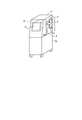
- the perspective view of the dialysis apparatus concerning a present Example The liquid circuit diagram of the dialysis apparatus concerning a present Example.
- FIG. 1 shows an overall view of a dialysis machine 1 and FIG. 2 shows a liquid circuit provided inside the dialysis machine 1.
- the dialysis machine 1 is a dialysate for one patient. This is a personal dialysis machine that performs dialysis treatment.
- the dialyzer 1 constitutes a dialyzer 2 held in the main body 1a, a blood circuit 3 connected to the dialyzer 2, a dialysate circuit 4 provided in the main body 1a, and a concentration monitoring device.
- the control means 1b to perform is provided.
- the control means 1b is provided with a touch panel type input unit 1c that can perform a required operation. The operator sets the concentration of the dialysate used during dialysis treatment by operating the input unit 1c. It has become.
- a hollow fiber (not shown) is provided inside the dialyzer 2.
- the hollow fiber communicates with the blood circuit 3 to allow blood to flow.
- the hollow fiber communicates with the dialysate circuit 4.
- the dialysate flows in the opposite direction to the blood.
- a dialysate circuit 4 shown in FIG. 2 includes a water supply means (not shown) for supplying purified water such as RO water as dilution water, an A solution container 5 for supplying solution A as a dialysate concentrate, and a dialysate concentrate.
- the B liquid container 6 for supplying the B liquid is connected to a drain pipe (not shown) through which the used dialysate is discharged.
- the purified water supplied from the water supply means in the dialysate circuit 4 the A liquid supplied from the A liquid container 5, and the B liquid supplied from the B liquid container 6 are mixed and dialyzed.
- Dialysis treatment is performed by preparing a liquid and supplying the dialysate to the dialyzer 2.
- the dialysate circuit 4 includes two first and second chambers 11 and 12, a water supply passage 13 connected to the first and second chambers 11 and 12 through which purified water from the water supply means flows, and the water supply A liquid supply passage 14 connected to the passage 13 through which the A liquid in the A liquid container 5 flows; B liquid supply passage 15 connected to the water supply passage 13 through which the B liquid in the B liquid container 6 flows; An unused dialysate passage 16 which is provided between the first and second chambers 11 and 12 and the dialyzer 2 and through which unused dialysate flows, the first and second chambers 11 and 12 and the dialyzer 2 A used dialysate passage 17 through which the used dialysate flows and a drainage passage 18 for discharging the used dialysate from the first and second chambers 11 and 12 to the drainage pipe; It has.
- the first and second chambers 11 and 12 have the same shape, and the interior thereof is divided into two chambers by diaphragms 11a and 12a, and the water supply passage 13 and the unused dialysate passage are provided in one space on the right side in the figure. 16 is connected, and the used dialysate passage 17 and the drainage passage 18 are connected to the other space on the left side of the figure.
- the water supply passage 13 is provided with a water purification pump P1 that adjusts the supply amount of purified water under the control of the control means 1b, and the downstream portion of the water supply passage 13 branches in two directions, and the first and second chambers 11 respectively. , 12 and solenoid valves V1, V2 are provided at the branch portions, respectively.
- the A liquid supply passage 14 is connected to the upstream side of the branch portion in the water supply passage 13 and includes an A liquid pump P2.
- the A liquid pump P2 controls the supply amount of the A liquid under the control of the control means 1b. It is possible to adjust.
- the B liquid supply passage 15 is connected upstream of the connection position of the A liquid supply passage 14 in the water supply passage 13 and includes a B liquid pump P3.
- the B liquid pump P3 is controlled by the control means 1b. It is possible to adjust the supply amount of the B liquid.
- the water purification pump P1, the A liquid pump P2, and the B liquid pump P3 constitute a concentration adjusting means that is provided in the concentration monitoring device and adjusts the mixing amount of the A liquid, the B liquid, and the dilution water.
- the unused dialysate passage 16 has its upstream portion branched in two directions and connected to the first and second chambers 11 and 12, respectively, and electromagnetic valves V3 and V4 are provided at the branched portions, respectively. .
- the unused dialysate passage 16 has a conductivity sensor S as a conductivity measuring means for measuring the electrical conductivity of the dialysate prepared in the first and second chambers 11 and 12, and is not used downstream thereof. And an electromagnetic valve V5 for closing the dialysate passage 16.
- the used dialysate passage 17 has a downstream portion branched in two directions and connected to the first and second chambers 11 and 12, respectively, and solenoid valves V6 and V7 are provided at the branched portions, respectively. .
- the used dialysate passage 17 is provided with a dialysate pump P4 for feeding the dialysate in the dialyzer 2, and this dialysate pump P4 is dialyzed through the dialyzer 2 under the control of the control means 1b. The flow rate of the liquid is adjusted. Further, a defective dialysate discharge passage 19 is arranged between the conductivity sensor S and the solenoid valve V5 in the unused dialysate passage 16 and between the upstream side of the dialysate pump P4 in the used dialysate passage 17. The defective dialysate discharge passage 19 is provided with a solenoid valve V8.
- the drainage passage 18 has an upstream portion branched in two directions and connected to the first and second chambers 11 and 12, respectively, and electromagnetic valves V9 and V10 are provided at the branch portions, respectively.
- a water removal passage 20 is provided between the used dialysis passage 17 and the drainage passage 18, and a water removal pump P5 is provided in the water removal passage 20, and the above-mentioned during the dialysis treatment. By operating the water removal pump P ⁇ b> 5, a water removal equivalent amount is directly discharged into the liquid discharge passage 18.
- the electromagnetic valve V1 on the first chamber 11 side in the water supply passage 13 is opened, the electromagnetic valve V2 on the second chamber 12 side is closed, and the unused dialysate passage 16 is provided.
- the electromagnetic valve V6 on the first chamber 11 side in the used dialysate passage 17 is closed.
- the electromagnetic valve V7 on the second chamber 12 side is opened, the electromagnetic valve V9 on the first chamber 11 side in the drainage passage 18 is opened, and the electromagnetic valve V10 on the second chamber 12 side is closed. It has become.
- the purified water pump P1 sends purified water supplied from the water supply means in a predetermined supply amount
- the A solution pump P2 sends A solution from the A solution container 5 in a specified supply amount
- the B liquid pump P3 feeds the B liquid from the B liquid container 6 at a predetermined supply amount.
- the purified water, the A liquid, and the B liquid flow into one space of the first chamber 11 at a predetermined ratio, and are mixed to create an unused dialysate having a preset concentration.
- the used dialysate has already been stored in the other space of the first chamber 11, and the purified water, the A liquid, and the B liquid flow into the one space of the first chamber 11.
- the spent dialysate is pushed out into the drainage passage 18 through the diaphragm 11a and discharged into the drainage pipe.
- the dialysate pump P4 feeds the used dialysate in the used dialysate passage 17 at a predetermined flow rate, so that the unused dialysate prepared in one space of the second chamber 12 is unused dialyzed. It is supplied to the dialyzer 2 through the liquid passage 16. At the same time, the spent dialysate flows from the dialyzer 2 into the other space of the second chamber 12.
- the first chamber 11 and the second chamber 12 are alternately dialyzed by switching the open / close states of the solenoid valves V1, V2, V3, V4, V6, V7, V9, and V10. A liquid is prepared and a dialysate is supplied.
- the unused dialysate that has flowed out into the unused dialysate passage 16 is measured for electrical conductivity by a conductivity sensor S as a conductivity measuring means provided in the unused dialysate passage 16 and is used as a concentration monitoring device as control means.
- 1b compares the measured electrical conductivity with a preset reference value to determine whether or not the concentration of the unused dialysate is appropriate.
- the control unit 1b determines that the concentration of this unused dialysate is appropriate.
- the control means 1b determines that the concentration of the unused dialysate is abnormal, outputs an alarm command, and displays an alarm on the input unit 1c. Further, the electromagnetic valve V5 is closed and the electromagnetic valve V8 is opened, so that the unused dialysate is discharged to the defective dialysate discharge passage 19 and the used dialysate passage 17.
- dialysis is performed by supplying the dialysate 2 to the dialyzer 2 while supplying the purified water, the A liquid, and the B liquid to the first chamber 11 and the second chamber 12.
- concentration of the dialysate produced is monitored by measuring its electrical conductivity.
- the conductivity sensor S for measuring the electrical conductivity of the dialysate and the control means 1b for comparing the reference value with the measured electrical conductivity constitute a dialysate concentration monitoring device.
- the concentration of the dialysate to be created can be set according to the individual patient, and the operator can set the A solution concentration in the input unit 1c of the dialyzer 1.
- the concentration monitoring device automatically changes the reference value for monitoring the concentration, and monitors the changed concentration of the dialysate.
- the concentration monitoring apparatus of the present embodiment is provided with setting changing means for changing the setting of the reference value, and the concentration of the dialysate newly created by the setting changing means is adjusted to the concentration of the A liquid and the B liquid.
- the electric conductivity is obtained, and a new reference value is set from here, and the control means 1b monitors the concentration of the dialysate prepared based on this new reference value. Yes.
- FIG. 3 shows a setting screen displayed on the input unit 1c of the dialysis device 1, and this setting operation is performed before dialysis treatment. This is done in advance.
- the sample numbers 1 to 5 in order from the left side, concentration of solution A (mEq / L), concentration of solution B (mEq / L), dialysate solution consisting of these concentrations of solution A and solution B, The electric conductivity (mS / cm) is shown, and below the table, there are provided columns for inputting the A solution concentration and B solution concentration of the dialysate used during dialysis treatment.
- the value of sample number 1 is the basic concentration and the basic electrical conductivity
- the operator inputs the basic concentrations of the liquid A and the liquid B of the sample number 1 from the input unit 1c as the basic electrical conductivity.
- the values of the dialysate used at the start of treatment are input as the concentration of solution A and solution B input as the basic concentrations, but values previously registered in the control means 1b are used. Also good.
- Concentration adjusting means automatically sets the concentration of solution A and the concentration of solution B for sample numbers 2 to 4 with respect to the concentrations of solution A and solution B as the basic concentrations.
- the values of sample numbers 2 and 3 are obtained by making the B solution concentration different from the basic concentration of sample number 1 by a predetermined amount by 10 mEq / L with respect to the basic concentration.
- Sample number 2 has a low B liquid concentration
- sample number 3 has a high B liquid concentration.
- the values of sample numbers 4 and 5 are obtained by changing the concentration of solution A by a predetermined amount with respect to the basic concentration of sample number 1, and each sample number 4 is 20 mEq / L with respect to the basic concentration.
- the liquid concentration is high, and Sample No. 5 has a low A liquid concentration.
- the value set by the concentration adjusting means at this time is preferably in a range that includes the A solution concentration and the B solution concentration of the dialysate prepared during dialysis treatment.
- the concentration adjusting means sets the A liquid concentration and the B liquid concentration of sample numbers 2 to 5
- the concentration adjusting means is based on the A liquid concentration and B liquid concentration of sample number 1 prior to treatment.
- the purified water pump P1, the A liquid pump P2, and the B liquid pump P3 are controlled, and the dialysate is prepared in the first and second chambers 11 and 12.
- the dialysate is discharged from the first and second chambers 11 and 12 and flows through the unused dialysate passage 16, and the electrical conductivity is measured by the conductivity sensor S.
- the conductivity is registered in the setting change means as the basic electrical conductivity of sample number 1 and displayed in a table on the screen.
- dialysate was prepared based on the concentrations of solution A and solution B, and the electrical conductivity of each of the prepared dialysate was measured. Register the measured value in and display it in the table on the screen.
- the setting changing means calculates the A liquid concentration from the A liquid concentration value and the measured electrical conductivity value. The rate of change in the electrical conductivity of the dialysate relative to the change in concentration is obtained.
- the setting changing means calculates the B solution from the B solution concentration value and the measured electrical conductivity value. Determine the rate of change in the electrical conductivity of the dialysate relative to the change in concentration.
- the slope of the straight line A obtained from the values of sample numbers 1, 4 and 5 that differ only in the concentration of solution A corresponds to the rate of change in the electrical conductivity of the dialysate relative to the change in concentration of solution A.
- the slope of the straight line B obtained from the values of sample numbers 1, 2, and 3 that differ only in the B liquid concentration corresponds to the ratio of the change in the electrical conductivity of the dialysate with respect to the change in the B liquid concentration.
- the electrical conductivity of the dialysate prepared based on the obtained change rate of electrical conductivity is obtained, and a reference value for concentration monitoring is set from the electrical conductivity. .
- the basic electrical conductivity measured above is set, and the basic electrical conductivity is corrected based on the rate of change, thereby obtaining the electrical conductivity of the dialysate to be created. Yes.
- the slope of the straight line A is 0.1
- the slope of the straight line B is 0.025.
- the basic electrical conductivity is corrected and the electrical conductivity of the dialysate to be created is obtained.
- a dialysis fluid having a basic concentration of 110 mEq / L for liquid A, 30 mEq / L for liquid B, and a basic electrical conductivity of 14.00 mS / cm is newly created.
- the case where the dialysate solution A concentration is 100 mEq / L and the solution B concentration is 20 mEq / L will be described.
- the setting change means obtains the difference between the basic concentration and the newly created concentration for the liquid A.
- the difference in concentration is ⁇ 10 mEq / L.
- the electric power increased or decreased with respect to the basic electric conductivity from the difference in the concentration of the liquid A and the ratio of the change in the electric conductivity of the dialysate with respect to the concentration change of the liquid A alone (slope of the straight line A).
- the conductivity value is, in the case of the above example, when the concentration of solution A changes by -10 mEq / L, the electric conductivity changes by an amount multiplied by 0.1, and therefore changes by -1 mS / cm with respect to the basic electric conductivity. It will be.
- the setting changing means obtains the difference between the basic concentration and the newly created concentration for the B liquid.
- the difference in concentration is ⁇ 10 mEq / L.
- the electric power increased or decreased with respect to the basic electric conductivity from the difference in the B liquid concentration obtained and the rate of change in the electric conductivity of the dialysate with respect to the concentration change of only the B liquid (slope of the straight line B).
- the conductivity value is, in the case of the above example, when the concentration of solution B changes by ⁇ 10 mEq / L, the electric conductivity changes by an amount multiplied by 0.025, and therefore ⁇ 0.25 mS / cm with respect to the basic electric conductivity. Will change.
- the basic electrical conductivity is corrected by using the change amount of the electrical conductivity corresponding to the change in the concentration of the liquid A and the liquid B obtained above, and in this example, the basic electrical conductivity is 14.00 mS.
- a new electric conductivity obtained by subtracting 1.00 mS / cm for liquid A and 0.25 mS / cm for liquid B a value of 12.75 mS / cm is obtained.
- the setting changing means sets a reference value for monitoring the concentration of a newly created dialysate from the obtained electrical conductivity, and registers the reference value in the control means 1b as a concentration monitoring device.
- the control means 1b monitors the dialysate based on this reference value.
- the concentration monitoring device when a predetermined basal concentration is set in the concentration monitoring device, first, the electric conductivity of the dialysate composed of this basal concentration is measured, and this is set as the basal electric conductivity. Yes. Next, the difference between the concentration of solution A as the basic concentration and the concentration of solution A of the newly prepared dialysate is obtained, and based on the rate of change in the electrical conductivity of the dialysate that changes only the concentration of solution A. The value of electrical conductivity that is increased or decreased from the basic electrical conductivity is obtained.
- the difference between the B liquid concentration as the basal concentration and the B liquid concentration of the newly prepared dialysate is obtained, and based on the rate of change in the electrical conductivity of the dialysate with only the B liquid concentration changed, the basic The value of the electrical conductivity that is increased or decreased from the electrical conductivity is obtained. And the said basic electrical conductivity is correct
- the control means 1b obtains the electrical conductivity of the dialysate to be created, and the concentration monitoring The reference value is set automatically. This makes it possible to change the dialysate concentration even during dialysis treatment.
- the electrical conductivity of the dialysate with respect to changes in the concentrations of the A and B solutions Therefore, it is possible to determine the electrical conductivity of the dialysate as accurately as possible.
- Dialysis apparatus 1b Control means 4 Dialysate circuit 5 A liquid container 6 B liquid container 13 Water supply path 14 A liquid supply path 15 B liquid supply path 16 Unused dialysate path S Conductivity sensor
Abstract
The concentration of a dialysate, which is prepared by mixing solution A and solution B with diluent water, is monitored by measuring the electric conductivity of the dialysate and comparing the electric conductivity with a preset standard.
First, the changing ratio of the electric conductivity of the dialysate to the change of the concentration of solution A alone (line A) and the changing ratio of the electric conductivity of the dialysate to the change of the concentration of solution B alone (line B) are determined.
Next, the electric conductivity of the dialysate to be prepared is determined based on the changing ratios of the electric conductivity of the dialysate to the change of the concentration of solution A and to the change of the concentration of solution B as described above, relative to the concentration of solution A and the concentration of solution B in the dialysate to be prepared. Then, the aforesaid standard is set from the electric conductivity thus determined.
Thus, the electric conductivity can be easily set depending on the concentration of the dialysate and a concentration change during a dialysis treatment can be dealt with.
Description
本発明は透析液の濃度監視方法およびその装置に関し、詳しくは透析液の電気伝導度を測定し、該電気伝導度を予め定めた基準値と比較しながら上記透析液の濃度を監視する透析液の濃度監視方法およびその装置に関する。
The present invention relates to a dialysate concentration monitoring method and apparatus, and more particularly, to measure the electrical conductivity of a dialysate and monitor the dialysate concentration while comparing the electrical conductivity with a predetermined reference value. The present invention relates to a concentration monitoring method and apparatus therefor.
従来、個人用透析装置においては、A液とB液と希釈水とを混合して透析液を作成し、作成した透析液を透析器へ供給するようになっており、また透析液の濃度を常に監視して、所定濃度から外れると供給を停止して警報を出力させるようになっている。
このような透析液の濃度監視方法として、透析液の濃度を電気伝導度によって測定するものが知られ、この方法では、透析装置に電気伝導度の測定手段を設けるとともに、予め作成する透析液についての電気伝導度の基準値を設定して、上記測定手段による測定値を上記基準値と比較することで、透析液が所定の濃度であるか否かを監視するようになっている(特許文献1)。
この特許文献1では、A液、B液に含まれる各成分の濃度を入力して、これらの成分濃度と混合比とから、作成しようとする透析液の電気伝導度の基準値を算出している。
なお、上記A液は、主に電解質とブトウ糖からなるA剤を水に溶解したものであり、B液は炭酸水素ナトリウムを主成分としたB剤を水に溶解したものである。また希釈水としては逆浸透膜を通して浄化したRO水を使用する。 Conventionally, in a personal dialysis machine, A liquid, B liquid and dilution water are mixed to prepare a dialysate, and the prepared dialysate is supplied to the dialyzer. Monitoring is always performed, and when the concentration falls outside the predetermined concentration, the supply is stopped and an alarm is output.
As such a dialysate concentration monitoring method, a method for measuring the dialysate concentration by electric conductivity is known. In this method, a dialyser is provided with a means for measuring electric conductivity, and a dialysate prepared in advance is used. By setting a reference value for the electrical conductivity, and comparing the value measured by the measuring means with the reference value, it is monitored whether or not the dialysate has a predetermined concentration (Patent Literature). 1).
In thispatent document 1, the concentration of each component contained in the A solution and the B solution is input, and the reference value of the electrical conductivity of the dialysate to be created is calculated from the concentration of these components and the mixing ratio. Yes.
In addition, the said A liquid dissolves A agent mainly consisting of electrolyte and butter sugar in water, and B liquid dissolves B agent which has sodium hydrogen carbonate as a main component in water. As dilution water, RO water purified through a reverse osmosis membrane is used.
このような透析液の濃度監視方法として、透析液の濃度を電気伝導度によって測定するものが知られ、この方法では、透析装置に電気伝導度の測定手段を設けるとともに、予め作成する透析液についての電気伝導度の基準値を設定して、上記測定手段による測定値を上記基準値と比較することで、透析液が所定の濃度であるか否かを監視するようになっている(特許文献1)。
この特許文献1では、A液、B液に含まれる各成分の濃度を入力して、これらの成分濃度と混合比とから、作成しようとする透析液の電気伝導度の基準値を算出している。
なお、上記A液は、主に電解質とブトウ糖からなるA剤を水に溶解したものであり、B液は炭酸水素ナトリウムを主成分としたB剤を水に溶解したものである。また希釈水としては逆浸透膜を通して浄化したRO水を使用する。 Conventionally, in a personal dialysis machine, A liquid, B liquid and dilution water are mixed to prepare a dialysate, and the prepared dialysate is supplied to the dialyzer. Monitoring is always performed, and when the concentration falls outside the predetermined concentration, the supply is stopped and an alarm is output.
As such a dialysate concentration monitoring method, a method for measuring the dialysate concentration by electric conductivity is known. In this method, a dialyser is provided with a means for measuring electric conductivity, and a dialysate prepared in advance is used. By setting a reference value for the electrical conductivity, and comparing the value measured by the measuring means with the reference value, it is monitored whether or not the dialysate has a predetermined concentration (Patent Literature). 1).
In this
In addition, the said A liquid dissolves A agent mainly consisting of electrolyte and butter sugar in water, and B liquid dissolves B agent which has sodium hydrogen carbonate as a main component in water. As dilution water, RO water purified through a reverse osmosis membrane is used.
ここで、上記電気伝導度の基準値は、作成する透析液の濃度を変更する際に同時に変更しなければならず、従来は透析装置の操作者が透析液の濃度と電気伝導度との対応表を参照する等して基準値の再設定を行っていた。
しかしながら透析液の電気伝導度は、透析液として濃度が等しい場合であってもA液とB液の混合比が異なると相違し、予め様々な濃度パターンを想定して、かつそれぞれの電気伝導度を測定しておくには多大な労力が必要であり、またこのような基準値の再設定は透析治療中に行うことができなかった。
また上記特許文献1においては、混合比を変更することで新たな基準値を算出することが可能であるが、基準値を算出するための基礎となる各成分濃度は、実測値ではなく名目上のものであるため、算出した基準値が作成された透析液の電気伝導度の実測値と相異することがあった。
このような問題に鑑み、本発明は作成する透析液の濃度に応じた電気伝導度の基準値の設定が容易であり、透析治療中の濃度変更にも対応可能な透析液の濃度監視方法およびその装置を提供するものである。 Here, the reference value of the electrical conductivity must be changed at the same time when changing the concentration of the dialysate to be created. Conventionally, the operator of the dialyzer has to respond to the correspondence between the dialysate concentration and the electrical conductivity. The reference value was reset by referring to the table.
However, the electrical conductivity of the dialysate is different if the mixing ratio of the liquid A and the liquid B is different even when the concentrations are the same as the dialysate. It took a lot of labor to measure the above-mentioned values, and resetting of the reference values could not be performed during dialysis treatment.
InPatent Document 1, it is possible to calculate a new reference value by changing the mixing ratio. However, each component concentration that is a basis for calculating the reference value is not an actual measurement value but a nominal value. Therefore, the calculated reference value may differ from the actually measured value of the electrical conductivity of the dialysate prepared.
In view of such problems, the present invention makes it easy to set a reference value of electrical conductivity according to the concentration of the dialysate to be created, and a dialysate concentration monitoring method that can cope with concentration changes during dialysis treatment and The apparatus is provided.
しかしながら透析液の電気伝導度は、透析液として濃度が等しい場合であってもA液とB液の混合比が異なると相違し、予め様々な濃度パターンを想定して、かつそれぞれの電気伝導度を測定しておくには多大な労力が必要であり、またこのような基準値の再設定は透析治療中に行うことができなかった。
また上記特許文献1においては、混合比を変更することで新たな基準値を算出することが可能であるが、基準値を算出するための基礎となる各成分濃度は、実測値ではなく名目上のものであるため、算出した基準値が作成された透析液の電気伝導度の実測値と相異することがあった。
このような問題に鑑み、本発明は作成する透析液の濃度に応じた電気伝導度の基準値の設定が容易であり、透析治療中の濃度変更にも対応可能な透析液の濃度監視方法およびその装置を提供するものである。 Here, the reference value of the electrical conductivity must be changed at the same time when changing the concentration of the dialysate to be created. Conventionally, the operator of the dialyzer has to respond to the correspondence between the dialysate concentration and the electrical conductivity. The reference value was reset by referring to the table.
However, the electrical conductivity of the dialysate is different if the mixing ratio of the liquid A and the liquid B is different even when the concentrations are the same as the dialysate. It took a lot of labor to measure the above-mentioned values, and resetting of the reference values could not be performed during dialysis treatment.
In
In view of such problems, the present invention makes it easy to set a reference value of electrical conductivity according to the concentration of the dialysate to be created, and a dialysate concentration monitoring method that can cope with concentration changes during dialysis treatment and The apparatus is provided.
すなわち、請求項1の発明にかかる透析液の濃度監視方法は、A液とB液と希釈水とを混合して作成される透析液の電気伝導度を測定し、該電気伝導度を予め定めた基準値と比較して濃度を監視する透析液の濃度監視方法において、
A液のみの濃度変化に対する透析液の電気伝導度の変化の割合と、B液のみの濃度変化に対する透析液の電気伝導度の変化の割合とを求め、
作成される透析液のA液濃度およびB液濃度に対応させて、上記A液およびB液の濃度変化に対する透析液の電気伝導度の変化の割合に基づき、作成される透析液の電気伝導度を求め、
該電気伝導度から上記基準値を設定することを特徴としている。 That is, the dialysate concentration monitoring method according to the first aspect of the invention measures the electrical conductivity of a dialysate prepared by mixing A liquid, B liquid and dilution water, and determines the electrical conductivity in advance. In the dialysate concentration monitoring method for monitoring the concentration compared to the reference value,
Obtain the ratio of the change in the electrical conductivity of the dialysate with respect to the change in the concentration of the liquid A alone and the ratio of the change in the electrical conductivity of the dialysate with respect to the change in the concentration of the liquid B alone.
The electrical conductivity of the dialysate prepared based on the ratio of the change in the electrical conductivity of the dialysate with respect to the change in the concentration of the A solution and the B solution, corresponding to the concentration of the A solution and the B solution. Seeking
The reference value is set from the electrical conductivity.
また請求項3の発明にかかる透析液の濃度監視装置は、設定された混合比に応じてA液とB液と希釈水とを混合して透析液を作成する透析装置に備えられ、
透析液の電気伝導度を測定する伝導度測定手段を備えて、測定された電気伝導度を予め定めた基準値と比較して濃度を監視する透析液の濃度監視装置において、
上記透析液のA液とB液と希釈水との混合量を調節する濃度調節手段と、上記基準値の設定を変更する設定変更手段とを備え、
上記濃度調節手段によって透析液のA液のみ濃度を変化させるとともにB液のみ濃度を変化させて、上記伝導度測定手段によってこれら複数通りの透析液の電気伝導度を測定し、
上記設定変更手段は、上記A液のみの濃度変化に対する透析液の電気伝導度の変化の割合と、上記B液のみの濃度変化に対する透析液の電気伝導度の変化の割合とを求め、
上記透析装置においてA液とB液と希釈水の混合比が異なる透析液を新たに作成する際には、上記設定変更手段は新たに作成される透析液のA液濃度およびB液濃度に対応させて、上記求めたA液およびB液の濃度変化に対する透析液の電気伝導度の変化の割合に基づき、新たに作成される透析液の電気伝導度を求め、該電気伝導度から上記基準値を設定することを特徴としている。 The dialysate concentration monitoring device according to the invention ofclaim 3 is provided in a dialyzer for preparing a dialysate by mixing A solution, B solution and dilution water according to a set mixing ratio,
In a dialysate concentration monitoring device comprising a conductivity measuring means for measuring the electrical conductivity of a dialysate and monitoring the concentration by comparing the measured electrical conductivity with a predetermined reference value,
Concentration adjusting means for adjusting the mixing amount of the A liquid, B liquid and dilution water of the dialysate, and setting changing means for changing the setting of the reference value,
The concentration adjusting means changes only the concentration of dialysate A and only the concentration of liquid B, and the conductivity measuring means measures the electrical conductivity of these multiple dialysates,
The setting change means obtains a rate of change in the electrical conductivity of the dialysate with respect to a change in the concentration of only the A liquid and a rate of change in the electrical conductivity of the dialysate with respect to a change in the concentration of only the B liquid,
When creating a new dialysate with different mixing ratios of A liquid, B liquid and dilution water in the dialyzer, the setting changing means corresponds to the A liquid concentration and B liquid concentration of the newly prepared dialysate. Then, based on the ratio of the change in the electrical conductivity of the dialysate with respect to the change in the concentration of the liquids A and B, the electrical conductivity of the newly prepared dialysate is determined, and the reference value is calculated from the electrical conductivity. It is characterized by setting.
透析液の電気伝導度を測定する伝導度測定手段を備えて、測定された電気伝導度を予め定めた基準値と比較して濃度を監視する透析液の濃度監視装置において、
上記透析液のA液とB液と希釈水との混合量を調節する濃度調節手段と、上記基準値の設定を変更する設定変更手段とを備え、
上記濃度調節手段によって透析液のA液のみ濃度を変化させるとともにB液のみ濃度を変化させて、上記伝導度測定手段によってこれら複数通りの透析液の電気伝導度を測定し、
上記設定変更手段は、上記A液のみの濃度変化に対する透析液の電気伝導度の変化の割合と、上記B液のみの濃度変化に対する透析液の電気伝導度の変化の割合とを求め、
上記透析装置においてA液とB液と希釈水の混合比が異なる透析液を新たに作成する際には、上記設定変更手段は新たに作成される透析液のA液濃度およびB液濃度に対応させて、上記求めたA液およびB液の濃度変化に対する透析液の電気伝導度の変化の割合に基づき、新たに作成される透析液の電気伝導度を求め、該電気伝導度から上記基準値を設定することを特徴としている。 The dialysate concentration monitoring device according to the invention of
In a dialysate concentration monitoring device comprising a conductivity measuring means for measuring the electrical conductivity of a dialysate and monitoring the concentration by comparing the measured electrical conductivity with a predetermined reference value,
Concentration adjusting means for adjusting the mixing amount of the A liquid, B liquid and dilution water of the dialysate, and setting changing means for changing the setting of the reference value,
The concentration adjusting means changes only the concentration of dialysate A and only the concentration of liquid B, and the conductivity measuring means measures the electrical conductivity of these multiple dialysates,
The setting change means obtains a rate of change in the electrical conductivity of the dialysate with respect to a change in the concentration of only the A liquid and a rate of change in the electrical conductivity of the dialysate with respect to a change in the concentration of only the B liquid,
When creating a new dialysate with different mixing ratios of A liquid, B liquid and dilution water in the dialyzer, the setting changing means corresponds to the A liquid concentration and B liquid concentration of the newly prepared dialysate. Then, based on the ratio of the change in the electrical conductivity of the dialysate with respect to the change in the concentration of the liquids A and B, the electrical conductivity of the newly prepared dialysate is determined, and the reference value is calculated from the electrical conductivity. It is characterized by setting.
上記請求項1および請求項3の発明によれば、A液のみの濃度変化に対する透析液の電気伝導度の変化の割合と、B液のみの濃度変化に対する透析液の電気伝導度の変化の割合とを求めることにより、作成される透析液の電気伝導度を求めることができる。
これにより、透析液の濃度監視において、作成する透析液の濃度に応じた電気伝導度の基準値を容易に設定することができ、また透析治療中の濃度変更に対応することができる。 According to the first and third aspects of the invention, the rate of change in the electrical conductivity of the dialysate with respect to the change in the concentration of only the liquid A, and the rate of change in the electrical conductivity of the dialysate with respect to the change in the concentration of only the B solution It is possible to obtain the electrical conductivity of the dialysate to be created.
Thereby, in the dialysate concentration monitoring, the reference value of the electrical conductivity according to the concentration of the dialysate to be created can be easily set, and the concentration change during dialysis treatment can be dealt with.
以下図示実施例について説明すると、図1は透析装置1の全体図を、図2は該透析装置1の内部に設けた液回路を示し、この透析装置1は1人の患者を対象に透析液を作成し透析治療を行う個人用透析装置である。
上記透析装置1は、本体部1aに保持された透析器2と、該透析器2に接続された血液回路3と、本体部1aの内部に設けた透析液回路4および、濃度監視装置を構成する制御手段1bを備えている。
上記制御手段1bには、所要の操作が可能なタッチパネル式の入力部1cが設けられており、透析治療時に使用する透析液の濃度設定は、操作者がこの入力部1cを操作して行うようになっている。
上記透析器2の内部には図示しない中空糸が設けられており、この中空糸の内部は上記血液回路3と連通して血液が流通し、中空糸の外部は上記透析液回路4と連通して透析液が血液とは逆方向に流通する。
図2に示す透析液回路4には、希釈水としてRO水のような浄水を供給する図示しない給水手段と、透析液の原液であるA液を供給するA液容器5と、透析液の原液であるB液を供給するB液容器6と、使用済みの透析液が排出される図示しない排液管とが接続されている。
そして上記透析装置1では、上記透析液回路4において上記給水手段が供給する浄水と、A液容器5より供給されるA液と、B液容器6より供給されるB液とを混合して透析液を作成し、該透析液を上記透析器2に供給することで透析治療を行うようになっている。 FIG. 1 shows an overall view of adialysis machine 1 and FIG. 2 shows a liquid circuit provided inside the dialysis machine 1. The dialysis machine 1 is a dialysate for one patient. This is a personal dialysis machine that performs dialysis treatment.
Thedialyzer 1 constitutes a dialyzer 2 held in the main body 1a, a blood circuit 3 connected to the dialyzer 2, a dialysate circuit 4 provided in the main body 1a, and a concentration monitoring device. The control means 1b to perform is provided.
The control means 1b is provided with a touch paneltype input unit 1c that can perform a required operation. The operator sets the concentration of the dialysate used during dialysis treatment by operating the input unit 1c. It has become.
A hollow fiber (not shown) is provided inside thedialyzer 2. The hollow fiber communicates with the blood circuit 3 to allow blood to flow. The hollow fiber communicates with the dialysate circuit 4. The dialysate flows in the opposite direction to the blood.
Adialysate circuit 4 shown in FIG. 2 includes a water supply means (not shown) for supplying purified water such as RO water as dilution water, an A solution container 5 for supplying solution A as a dialysate concentrate, and a dialysate concentrate. The B liquid container 6 for supplying the B liquid is connected to a drain pipe (not shown) through which the used dialysate is discharged.
In thedialysis machine 1, the purified water supplied from the water supply means in the dialysate circuit 4, the A liquid supplied from the A liquid container 5, and the B liquid supplied from the B liquid container 6 are mixed and dialyzed. Dialysis treatment is performed by preparing a liquid and supplying the dialysate to the dialyzer 2.
上記透析装置1は、本体部1aに保持された透析器2と、該透析器2に接続された血液回路3と、本体部1aの内部に設けた透析液回路4および、濃度監視装置を構成する制御手段1bを備えている。
上記制御手段1bには、所要の操作が可能なタッチパネル式の入力部1cが設けられており、透析治療時に使用する透析液の濃度設定は、操作者がこの入力部1cを操作して行うようになっている。
上記透析器2の内部には図示しない中空糸が設けられており、この中空糸の内部は上記血液回路3と連通して血液が流通し、中空糸の外部は上記透析液回路4と連通して透析液が血液とは逆方向に流通する。
図2に示す透析液回路4には、希釈水としてRO水のような浄水を供給する図示しない給水手段と、透析液の原液であるA液を供給するA液容器5と、透析液の原液であるB液を供給するB液容器6と、使用済みの透析液が排出される図示しない排液管とが接続されている。
そして上記透析装置1では、上記透析液回路4において上記給水手段が供給する浄水と、A液容器5より供給されるA液と、B液容器6より供給されるB液とを混合して透析液を作成し、該透析液を上記透析器2に供給することで透析治療を行うようになっている。 FIG. 1 shows an overall view of a
The
The control means 1b is provided with a touch panel
A hollow fiber (not shown) is provided inside the
A
In the
上記透析液回路4は、2つの第1、第2チャンバ11,12と、上記第1、第2チャンバ11,12に接続されて上記給水手段からの浄水が流通する給水通路13と、上記給水通路13に接続されて上記A液容器5のA液が流通するA液供給通路14と、上記給水通路13に接続されて上記B液容器6のB液が流通するB液供給通路15と、第1、第2チャンバ11,12と透析器2との間に設けられて未使用の透析液が流通する未使用透析液通路16と、第1、第2チャンバ11,12と透析器2との間に設けられて使用済みの透析液が流通する使用済透析液通路17と、第1、第2チャンバ11,12から上記排液管へと使用済透析液を排出する排液通路18とを備えている。
上記第1、第2チャンバ11,12は同形であって、内部がダイアフラム11a,12aによって2室に区画されるとともに、一方の図示右方の空間には上記給水通路13および未使用透析液通路16が接続され、また他方の図示左方の空間には上記使用済透析液通路17および排液通路18が接続されている。 Thedialysate circuit 4 includes two first and second chambers 11 and 12, a water supply passage 13 connected to the first and second chambers 11 and 12 through which purified water from the water supply means flows, and the water supply A liquid supply passage 14 connected to the passage 13 through which the A liquid in the A liquid container 5 flows; B liquid supply passage 15 connected to the water supply passage 13 through which the B liquid in the B liquid container 6 flows; An unused dialysate passage 16 which is provided between the first and second chambers 11 and 12 and the dialyzer 2 and through which unused dialysate flows, the first and second chambers 11 and 12 and the dialyzer 2 A used dialysate passage 17 through which the used dialysate flows and a drainage passage 18 for discharging the used dialysate from the first and second chambers 11 and 12 to the drainage pipe; It has.
The first and second chambers 11 and 12 have the same shape, and the interior thereof is divided into two chambers by diaphragms 11a and 12a, and the water supply passage 13 and the unused dialysate passage are provided in one space on the right side in the figure. 16 is connected, and the used dialysate passage 17 and the drainage passage 18 are connected to the other space on the left side of the figure.
上記第1、第2チャンバ11,12は同形であって、内部がダイアフラム11a,12aによって2室に区画されるとともに、一方の図示右方の空間には上記給水通路13および未使用透析液通路16が接続され、また他方の図示左方の空間には上記使用済透析液通路17および排液通路18が接続されている。 The
The first and
上記給水通路13には上記制御手段1bの制御により浄水の供給量を調節する浄水ポンプP1が設けられ、また給水通路13の下流部分は2方向に分岐してそれぞれ上記第1、第2チャンバ11,12に接続されるとともに、該分岐部分にはそれぞれ電磁弁V1,V2が設けられている。
上記A液供給通路14は、上記給水通路13における上記分岐部分の上流側に接続されるとともにA液ポンプP2を備え、このA液ポンプP2は上記制御手段1bの制御によりA液の供給量を調節することが可能となっている。
上記B液供給通路15は、上記給水通路13におけるA液供給通路14の接続位置よりも上流側に接続されるとともにB液ポンプP3を備え、このB液ポンプP3は上記制御手段1bの制御によりB液の供給量を調節することが可能となっている。
そしてこれら浄水ポンプP1、A液ポンプP2およびB液ポンプP3により、濃度監視装置に備えられてA液とB液と希釈水との混合量を調節する濃度調節手段が構成されている。 Thewater supply passage 13 is provided with a water purification pump P1 that adjusts the supply amount of purified water under the control of the control means 1b, and the downstream portion of the water supply passage 13 branches in two directions, and the first and second chambers 11 respectively. , 12 and solenoid valves V1, V2 are provided at the branch portions, respectively.
The Aliquid supply passage 14 is connected to the upstream side of the branch portion in the water supply passage 13 and includes an A liquid pump P2. The A liquid pump P2 controls the supply amount of the A liquid under the control of the control means 1b. It is possible to adjust.
The Bliquid supply passage 15 is connected upstream of the connection position of the A liquid supply passage 14 in the water supply passage 13 and includes a B liquid pump P3. The B liquid pump P3 is controlled by the control means 1b. It is possible to adjust the supply amount of the B liquid.
The water purification pump P1, the A liquid pump P2, and the B liquid pump P3 constitute a concentration adjusting means that is provided in the concentration monitoring device and adjusts the mixing amount of the A liquid, the B liquid, and the dilution water.
上記A液供給通路14は、上記給水通路13における上記分岐部分の上流側に接続されるとともにA液ポンプP2を備え、このA液ポンプP2は上記制御手段1bの制御によりA液の供給量を調節することが可能となっている。
上記B液供給通路15は、上記給水通路13におけるA液供給通路14の接続位置よりも上流側に接続されるとともにB液ポンプP3を備え、このB液ポンプP3は上記制御手段1bの制御によりB液の供給量を調節することが可能となっている。
そしてこれら浄水ポンプP1、A液ポンプP2およびB液ポンプP3により、濃度監視装置に備えられてA液とB液と希釈水との混合量を調節する濃度調節手段が構成されている。 The
The A
The B
The water purification pump P1, the A liquid pump P2, and the B liquid pump P3 constitute a concentration adjusting means that is provided in the concentration monitoring device and adjusts the mixing amount of the A liquid, the B liquid, and the dilution water.
上記未使用透析液通路16は、その上流部分が2方向に分岐してそれぞれ上記第1、第2チャンバ11,12に接続され、この分岐部分にはそれぞれ電磁弁V3,V4が設けられている。
また、未使用透析液通路16には第1、第2チャンバ11,12で作成した透析液の電気伝導度を測定する伝導度測定手段としての導電度センサSと、またその下流側に未使用透析液通路16を閉鎖する電磁弁V5とを備えている。
上記使用済透析液通路17は、その下流部分が2方向に分岐してそれぞれ上記第1、第2チャンバ11,12に接続され、この分岐部分にはそれぞれ電磁弁V6,V7が設けられている。
また、使用済透析液通路17には透析器2内の透析液を送液する透析液ポンプP4が設けられ、この透析液ポンプP4は上記制御手段1bの制御により上記透析器2を流通する透析液の流量を調節するようになっている。
さらに、未使用透析液通路16における上記導電度センサSと電磁弁V5の間と、使用済透析液通路17における透析液ポンプP4の上流側との間には、不良透析液排出通路19が配設されており、この不良透析液排出通路19には電磁弁V8が設けられている。
上記排液通路18は、その上流部分が2方向に分岐してそれぞれ上記第1、第2チャンバ11,12に接続され、この分岐部分にはそれぞれ電磁弁V9,V10が設けられている。
そして、使用済透析通路17と排液通路18との間には除水通路20が配設されるとともに、該除水通路20には除水ポンプP5が設けられており、透析治療中に上記除水ポンプP5を作動させることにより、除水相当量を排液通路18に直接排液するようになっている。 Theunused dialysate passage 16 has its upstream portion branched in two directions and connected to the first and second chambers 11 and 12, respectively, and electromagnetic valves V3 and V4 are provided at the branched portions, respectively. .
Theunused dialysate passage 16 has a conductivity sensor S as a conductivity measuring means for measuring the electrical conductivity of the dialysate prepared in the first and second chambers 11 and 12, and is not used downstream thereof. And an electromagnetic valve V5 for closing the dialysate passage 16.
The useddialysate passage 17 has a downstream portion branched in two directions and connected to the first and second chambers 11 and 12, respectively, and solenoid valves V6 and V7 are provided at the branched portions, respectively. .
The useddialysate passage 17 is provided with a dialysate pump P4 for feeding the dialysate in the dialyzer 2, and this dialysate pump P4 is dialyzed through the dialyzer 2 under the control of the control means 1b. The flow rate of the liquid is adjusted.
Further, a defectivedialysate discharge passage 19 is arranged between the conductivity sensor S and the solenoid valve V5 in the unused dialysate passage 16 and between the upstream side of the dialysate pump P4 in the used dialysate passage 17. The defective dialysate discharge passage 19 is provided with a solenoid valve V8.
Thedrainage passage 18 has an upstream portion branched in two directions and connected to the first and second chambers 11 and 12, respectively, and electromagnetic valves V9 and V10 are provided at the branch portions, respectively.
Awater removal passage 20 is provided between the used dialysis passage 17 and the drainage passage 18, and a water removal pump P5 is provided in the water removal passage 20, and the above-mentioned during the dialysis treatment. By operating the water removal pump P <b> 5, a water removal equivalent amount is directly discharged into the liquid discharge passage 18.
また、未使用透析液通路16には第1、第2チャンバ11,12で作成した透析液の電気伝導度を測定する伝導度測定手段としての導電度センサSと、またその下流側に未使用透析液通路16を閉鎖する電磁弁V5とを備えている。
上記使用済透析液通路17は、その下流部分が2方向に分岐してそれぞれ上記第1、第2チャンバ11,12に接続され、この分岐部分にはそれぞれ電磁弁V6,V7が設けられている。
また、使用済透析液通路17には透析器2内の透析液を送液する透析液ポンプP4が設けられ、この透析液ポンプP4は上記制御手段1bの制御により上記透析器2を流通する透析液の流量を調節するようになっている。
さらに、未使用透析液通路16における上記導電度センサSと電磁弁V5の間と、使用済透析液通路17における透析液ポンプP4の上流側との間には、不良透析液排出通路19が配設されており、この不良透析液排出通路19には電磁弁V8が設けられている。
上記排液通路18は、その上流部分が2方向に分岐してそれぞれ上記第1、第2チャンバ11,12に接続され、この分岐部分にはそれぞれ電磁弁V9,V10が設けられている。
そして、使用済透析通路17と排液通路18との間には除水通路20が配設されるとともに、該除水通路20には除水ポンプP5が設けられており、透析治療中に上記除水ポンプP5を作動させることにより、除水相当量を排液通路18に直接排液するようになっている。 The
The
The used
The used
Further, a defective
The
A
上記構成を有する透析装置1においては、上記給水通路13における第1チャンバ11側の電磁弁V1が開放され、第2チャンバ12側の電磁弁V2が閉鎖され、また、上記未使用透析液通路16における第1チャンバ11側の電磁弁V3が閉鎖され、第2チャンバ12側の電磁弁V4が開放された状態では、上記使用済透析液通路17における第1チャンバ11側の電磁弁V6が閉鎖され、第2チャンバ12側の電磁弁V7が開放され、そして、上記排液通路18における第1チャンバ11側の電磁弁V9が開放され、第2チャンバ12側の電磁弁V10が閉鎖されるようになっている。
この状態では、上記浄水ポンプP1が給水手段から供給された浄水を所定供給量で送液し、これと同時に上記A液ポンプP2がA液容器5からA液を所定供給量で送液し、上記B液ポンプP3がB液容器6からB液を所定供給量で送液する。
これにより、上記第1チャンバ11の一方の空間には所定の割合で浄水とA液とB液とが流入し、これらが混合されて予め設定された濃度の未使用透析液が作成される。
これと同時に、第1チャンバ11の他方の空間には既に使用済透析液が貯溜されており、上記第1チャンバ11の一方の空間への浄水とA液とB液との流入に伴なって、ダイアフラム11aを介して使用済透析液が排液通路18に押し出され、上記排液管に排出される。
一方、上記透析液ポンプP4は使用済透析液通路17の使用済透析液を所定の流量で送液し、これにより第2チャンバ12の一方の空間で作成された未使用透析液が未使用透析液通路16を介して透析器2に供給される。これと同時に、第2チャンバ12の他方の空間に透析器2から使用済透析液が流入する。
そして、所定時間が経過する毎に、各電磁弁V1、V2、V3、V4、V6、V7、V9、V10の開閉状態を切換えることにより、第1チャンバ11と第2チャンバ12とで交互に透析液を作成し、また、透析液の供給を行うようになっている。 In thedialysis apparatus 1 having the above-described configuration, the electromagnetic valve V1 on the first chamber 11 side in the water supply passage 13 is opened, the electromagnetic valve V2 on the second chamber 12 side is closed, and the unused dialysate passage 16 is provided. In the state where the electromagnetic valve V3 on the first chamber 11 side is closed and the electromagnetic valve V4 on the second chamber 12 side is opened, the electromagnetic valve V6 on the first chamber 11 side in the used dialysate passage 17 is closed. The electromagnetic valve V7 on the second chamber 12 side is opened, the electromagnetic valve V9 on the first chamber 11 side in the drainage passage 18 is opened, and the electromagnetic valve V10 on the second chamber 12 side is closed. It has become.
In this state, the purified water pump P1 sends purified water supplied from the water supply means in a predetermined supply amount, and at the same time, the A solution pump P2 sends A solution from theA solution container 5 in a specified supply amount, The B liquid pump P3 feeds the B liquid from the B liquid container 6 at a predetermined supply amount.
As a result, the purified water, the A liquid, and the B liquid flow into one space of thefirst chamber 11 at a predetermined ratio, and are mixed to create an unused dialysate having a preset concentration.
At the same time, the used dialysate has already been stored in the other space of thefirst chamber 11, and the purified water, the A liquid, and the B liquid flow into the one space of the first chamber 11. The spent dialysate is pushed out into the drainage passage 18 through the diaphragm 11a and discharged into the drainage pipe.
On the other hand, the dialysate pump P4 feeds the used dialysate in the useddialysate passage 17 at a predetermined flow rate, so that the unused dialysate prepared in one space of the second chamber 12 is unused dialyzed. It is supplied to the dialyzer 2 through the liquid passage 16. At the same time, the spent dialysate flows from the dialyzer 2 into the other space of the second chamber 12.
Then, every time a predetermined time elapses, thefirst chamber 11 and the second chamber 12 are alternately dialyzed by switching the open / close states of the solenoid valves V1, V2, V3, V4, V6, V7, V9, and V10. A liquid is prepared and a dialysate is supplied.
この状態では、上記浄水ポンプP1が給水手段から供給された浄水を所定供給量で送液し、これと同時に上記A液ポンプP2がA液容器5からA液を所定供給量で送液し、上記B液ポンプP3がB液容器6からB液を所定供給量で送液する。
これにより、上記第1チャンバ11の一方の空間には所定の割合で浄水とA液とB液とが流入し、これらが混合されて予め設定された濃度の未使用透析液が作成される。
これと同時に、第1チャンバ11の他方の空間には既に使用済透析液が貯溜されており、上記第1チャンバ11の一方の空間への浄水とA液とB液との流入に伴なって、ダイアフラム11aを介して使用済透析液が排液通路18に押し出され、上記排液管に排出される。
一方、上記透析液ポンプP4は使用済透析液通路17の使用済透析液を所定の流量で送液し、これにより第2チャンバ12の一方の空間で作成された未使用透析液が未使用透析液通路16を介して透析器2に供給される。これと同時に、第2チャンバ12の他方の空間に透析器2から使用済透析液が流入する。
そして、所定時間が経過する毎に、各電磁弁V1、V2、V3、V4、V6、V7、V9、V10の開閉状態を切換えることにより、第1チャンバ11と第2チャンバ12とで交互に透析液を作成し、また、透析液の供給を行うようになっている。 In the
In this state, the purified water pump P1 sends purified water supplied from the water supply means in a predetermined supply amount, and at the same time, the A solution pump P2 sends A solution from the
As a result, the purified water, the A liquid, and the B liquid flow into one space of the
At the same time, the used dialysate has already been stored in the other space of the
On the other hand, the dialysate pump P4 feeds the used dialysate in the used
Then, every time a predetermined time elapses, the
未使用透析液通路16に流出された未使用透析液は、該未使用透析液通路16に設けた導電度測定手段としての導電度センサSによって電気伝導度が測定され、濃度監視装置として制御手段1bはこの測定した電気伝導度を予め設定した基準値と比較し、未使用透析液の濃度が適正か否かを判定する。
未使用透析液の電気伝導度が上記基準値に対して例えば5%の誤差範囲に含まれる場合、制御手段1bはこの未使用透析液の濃度が適正であると判定する。
一方、±5%を超える誤差が検出された場合には、制御手段1bはこの未使用透析液の濃度が異常であると判定して警報指令を出力し、上記入力部1cに警報表示を行い、また上記電磁弁V5を閉鎖するとともに上記電磁弁V8を開放し、未使用透析液を不良透析液排出通路19および上記使用済透析液通路17へと排出するようになっている。 The unused dialysate that has flowed out into theunused dialysate passage 16 is measured for electrical conductivity by a conductivity sensor S as a conductivity measuring means provided in the unused dialysate passage 16 and is used as a concentration monitoring device as control means. 1b compares the measured electrical conductivity with a preset reference value to determine whether or not the concentration of the unused dialysate is appropriate.
When the electrical conductivity of the unused dialysate is included in an error range of, for example, 5% with respect to the reference value, thecontrol unit 1b determines that the concentration of this unused dialysate is appropriate.
On the other hand, if an error exceeding ± 5% is detected, the control means 1b determines that the concentration of the unused dialysate is abnormal, outputs an alarm command, and displays an alarm on theinput unit 1c. Further, the electromagnetic valve V5 is closed and the electromagnetic valve V8 is opened, so that the unused dialysate is discharged to the defective dialysate discharge passage 19 and the used dialysate passage 17.
未使用透析液の電気伝導度が上記基準値に対して例えば5%の誤差範囲に含まれる場合、制御手段1bはこの未使用透析液の濃度が適正であると判定する。
一方、±5%を超える誤差が検出された場合には、制御手段1bはこの未使用透析液の濃度が異常であると判定して警報指令を出力し、上記入力部1cに警報表示を行い、また上記電磁弁V5を閉鎖するとともに上記電磁弁V8を開放し、未使用透析液を不良透析液排出通路19および上記使用済透析液通路17へと排出するようになっている。 The unused dialysate that has flowed out into the
When the electrical conductivity of the unused dialysate is included in an error range of, for example, 5% with respect to the reference value, the
On the other hand, if an error exceeding ± 5% is detected, the control means 1b determines that the concentration of the unused dialysate is abnormal, outputs an alarm command, and displays an alarm on the
このように、上記透析装置1では上記第1チャンバ11および第2チャンバ12に浄水、A液、B液を供給して透析液を作成しながら該透析液を透析器2に供給することで透析治療を行い、その間、作成される透析液の濃度をその電気伝導度を測定することによって監視するようになっている。
そして、これら透析液の電気伝導度を測定する上記導電度センサSと、上記基準値と測定された電気導電度とを比較する制御手段1bとによって透析液の濃度監視装置を構成している。 As described above, in thedialysis apparatus 1, dialysis is performed by supplying the dialysate 2 to the dialyzer 2 while supplying the purified water, the A liquid, and the B liquid to the first chamber 11 and the second chamber 12. During the course of treatment, the concentration of the dialysate produced is monitored by measuring its electrical conductivity.
The conductivity sensor S for measuring the electrical conductivity of the dialysate and the control means 1b for comparing the reference value with the measured electrical conductivity constitute a dialysate concentration monitoring device.
そして、これら透析液の電気伝導度を測定する上記導電度センサSと、上記基準値と測定された電気導電度とを比較する制御手段1bとによって透析液の濃度監視装置を構成している。 As described above, in the
The conductivity sensor S for measuring the electrical conductivity of the dialysate and the control means 1b for comparing the reference value with the measured electrical conductivity constitute a dialysate concentration monitoring device.
次に、本実施例の透析装置1は、作成する透析液の濃度を、個々の患者に応じて設定することが可能となっており、操作者が透析装置1の入力部1cにA液濃度およびB液濃度が異なる複数の濃度パターンと、濃度を変更するタイミングとを入力することで、透析治療中に透析液の濃度を変更することが可能となっている。
この場合においても、上記濃度監視装置は濃度を監視するための基準値を自動的に変更して、変更された透析液の濃度を監視するようになっている。
このため、本実施例の濃度監視装置には、上記基準値の設定を変更する設定変更手段が設けられおり、該設定変更手段によって新たに作成する透析液のA液とB液との濃度に対応させて電気伝導度を求め、ここから新たな基準値を設定するようになっており、制御手段1bではこの新たな基準値に基づいて作成される透析液の濃度監視を行うようになっている。 Next, in thedialysis machine 1 of this embodiment, the concentration of the dialysate to be created can be set according to the individual patient, and the operator can set the A solution concentration in the input unit 1c of the dialyzer 1. In addition, it is possible to change the concentration of the dialysate during dialysis treatment by inputting a plurality of concentration patterns having different B solution concentrations and the timing for changing the concentration.
Even in this case, the concentration monitoring device automatically changes the reference value for monitoring the concentration, and monitors the changed concentration of the dialysate.
For this reason, the concentration monitoring apparatus of the present embodiment is provided with setting changing means for changing the setting of the reference value, and the concentration of the dialysate newly created by the setting changing means is adjusted to the concentration of the A liquid and the B liquid. Correspondingly, the electric conductivity is obtained, and a new reference value is set from here, and the control means 1b monitors the concentration of the dialysate prepared based on this new reference value. Yes.
この場合においても、上記濃度監視装置は濃度を監視するための基準値を自動的に変更して、変更された透析液の濃度を監視するようになっている。
このため、本実施例の濃度監視装置には、上記基準値の設定を変更する設定変更手段が設けられおり、該設定変更手段によって新たに作成する透析液のA液とB液との濃度に対応させて電気伝導度を求め、ここから新たな基準値を設定するようになっており、制御手段1bではこの新たな基準値に基づいて作成される透析液の濃度監視を行うようになっている。 Next, in the
Even in this case, the concentration monitoring device automatically changes the reference value for monitoring the concentration, and monitors the changed concentration of the dialysate.
For this reason, the concentration monitoring apparatus of the present embodiment is provided with setting changing means for changing the setting of the reference value, and the concentration of the dialysate newly created by the setting changing means is adjusted to the concentration of the A liquid and the B liquid. Correspondingly, the electric conductivity is obtained, and a new reference value is set from here, and the control means 1b monitors the concentration of the dialysate prepared based on this new reference value. Yes.
以下、上記濃度監視装置による濃度監視のための基準値の設定方法について説明すると、図3は透析装置1の入力部1cに表示される設定画面を示し、この設定作業は透析治療を行う前に予め行うようになっている。
画面に表示した表には、それぞれ左側から順に1~5のサンプルナンバー、A液濃度(mEq/L)、B液濃度(mEq/L)、これらA液濃度、B液濃度からなる透析液の電気伝導度(mS/cm)が示され、また表の下方には透析治療中に使用する透析液のA液濃度およびB液濃度を入力するための欄が設けられている。
ここで、サンプルナンバー1の値は基礎濃度および基礎電気伝導度であって、該サンプルナンバー1のA液およびB液の基礎濃度は操作者が入力部1cから入力し、上記基礎電気伝導度としては入力されたA液濃度、B液濃度に基づいて作成された透析液の実測値が表示される。
なお本実施例ではこの基礎濃度として入力するA液濃度およびB液濃度は治療開始時に用いる透析液の値を入力するようにしているが、予め制御手段1bに登録されている値を使用してもよい。
このような基礎濃度としてのA液濃度およびB液濃度に対して、濃度調節手段はサンプルナンバー2~4について、それぞれ自動的にA液濃度、B液濃度を設定する。
具体的に説明すると、サンプルナンバー2、3の値は、上記サンプルナンバー1の基礎濃度に対してB液濃度のみを所定量ずつ異ならせたものであり、基礎濃度に対してそれぞれ10mEq/Lずつサンプルナンバー2はB液濃度が低く、サンプルナンバー3はB液濃度が高くなっている。
またサンプルナンバー4、5の値は、上記サンプルナンバー1の基礎濃度に対してA液濃度だけを所定量ずつ異ならせたものであり、基礎濃度に対してそれぞれ20mEq/Lずつサンプルナンバー4はA液濃度が高く、サンプルナンバー5はA液濃度が低くなっている。
なお、このとき濃度調節手段にて設定する値は、透析治療中に作成する透析液のA液濃度およびB液濃度が含まれるような範囲であることが望ましい。 The reference value setting method for concentration monitoring by the concentration monitoring device will be described below. FIG. 3 shows a setting screen displayed on theinput unit 1c of the dialysis device 1, and this setting operation is performed before dialysis treatment. This is done in advance.
In the table displayed on the screen, thesample numbers 1 to 5 in order from the left side, concentration of solution A (mEq / L), concentration of solution B (mEq / L), dialysate solution consisting of these concentrations of solution A and solution B, The electric conductivity (mS / cm) is shown, and below the table, there are provided columns for inputting the A solution concentration and B solution concentration of the dialysate used during dialysis treatment.
Here, the value ofsample number 1 is the basic concentration and the basic electrical conductivity, and the operator inputs the basic concentrations of the liquid A and the liquid B of the sample number 1 from the input unit 1c as the basic electrical conductivity. Displays the measured value of the dialysate prepared based on the input A solution concentration and B solution concentration.
In the present embodiment, the values of the dialysate used at the start of treatment are input as the concentration of solution A and solution B input as the basic concentrations, but values previously registered in the control means 1b are used. Also good.
Concentration adjusting means automatically sets the concentration of solution A and the concentration of solution B forsample numbers 2 to 4 with respect to the concentrations of solution A and solution B as the basic concentrations.
More specifically, the values of sample numbers 2 and 3 are obtained by making the B solution concentration different from the basic concentration of sample number 1 by a predetermined amount by 10 mEq / L with respect to the basic concentration. Sample number 2 has a low B liquid concentration, and sample number 3 has a high B liquid concentration.
The values of sample numbers 4 and 5 are obtained by changing the concentration of solution A by a predetermined amount with respect to the basic concentration of sample number 1, and each sample number 4 is 20 mEq / L with respect to the basic concentration. The liquid concentration is high, and Sample No. 5 has a low A liquid concentration.
Note that the value set by the concentration adjusting means at this time is preferably in a range that includes the A solution concentration and the B solution concentration of the dialysate prepared during dialysis treatment.
画面に表示した表には、それぞれ左側から順に1~5のサンプルナンバー、A液濃度(mEq/L)、B液濃度(mEq/L)、これらA液濃度、B液濃度からなる透析液の電気伝導度(mS/cm)が示され、また表の下方には透析治療中に使用する透析液のA液濃度およびB液濃度を入力するための欄が設けられている。
ここで、サンプルナンバー1の値は基礎濃度および基礎電気伝導度であって、該サンプルナンバー1のA液およびB液の基礎濃度は操作者が入力部1cから入力し、上記基礎電気伝導度としては入力されたA液濃度、B液濃度に基づいて作成された透析液の実測値が表示される。
なお本実施例ではこの基礎濃度として入力するA液濃度およびB液濃度は治療開始時に用いる透析液の値を入力するようにしているが、予め制御手段1bに登録されている値を使用してもよい。
このような基礎濃度としてのA液濃度およびB液濃度に対して、濃度調節手段はサンプルナンバー2~4について、それぞれ自動的にA液濃度、B液濃度を設定する。
具体的に説明すると、サンプルナンバー2、3の値は、上記サンプルナンバー1の基礎濃度に対してB液濃度のみを所定量ずつ異ならせたものであり、基礎濃度に対してそれぞれ10mEq/Lずつサンプルナンバー2はB液濃度が低く、サンプルナンバー3はB液濃度が高くなっている。
またサンプルナンバー4、5の値は、上記サンプルナンバー1の基礎濃度に対してA液濃度だけを所定量ずつ異ならせたものであり、基礎濃度に対してそれぞれ20mEq/Lずつサンプルナンバー4はA液濃度が高く、サンプルナンバー5はA液濃度が低くなっている。
なお、このとき濃度調節手段にて設定する値は、透析治療中に作成する透析液のA液濃度およびB液濃度が含まれるような範囲であることが望ましい。 The reference value setting method for concentration monitoring by the concentration monitoring device will be described below. FIG. 3 shows a setting screen displayed on the
In the table displayed on the screen, the
Here, the value of
In the present embodiment, the values of the dialysate used at the start of treatment are input as the concentration of solution A and solution B input as the basic concentrations, but values previously registered in the control means 1b are used. Also good.
Concentration adjusting means automatically sets the concentration of solution A and the concentration of solution B for
More specifically, the values of
The values of
Note that the value set by the concentration adjusting means at this time is preferably in a range that includes the A solution concentration and the B solution concentration of the dialysate prepared during dialysis treatment.
このようにして濃度調節手段がサンプルナンバー2~5のA液濃度およびB液濃度を設定すると、該濃度調節手段は、治療に先立って、サンプルナンバー1のA液濃度およびB液濃度に基づいて、浄水ポンプP1、A液ポンプP2、B液ポンプP3を制御し、上記第1、第2チャンバ11,12で透析液を作成する。
この透析液は第1、第2チャンバ11,12から排出されて上記未使用透析液通路16を流通し、上記導電度センサSによって電気伝導度が測定され、制御手段1bはこの透析液の電気伝導度をサンプルナンバー1の基礎電気伝導度として設定変更手段に登録し、画面上の表に表示する。
そして、サンプルナンバー2~5についても、それぞれのA液濃度、B液濃度に基づいて透析液を作成するとともに、それぞれ作成された複数通りの透析液の電気伝導度を測定し、それぞれ設定変更手段に測定値を登録し、画面上の表に表示する。 In this way, when the concentration adjusting means sets the A liquid concentration and the B liquid concentration ofsample numbers 2 to 5, the concentration adjusting means is based on the A liquid concentration and B liquid concentration of sample number 1 prior to treatment. The purified water pump P1, the A liquid pump P2, and the B liquid pump P3 are controlled, and the dialysate is prepared in the first and second chambers 11 and 12.
The dialysate is discharged from the first and second chambers 11 and 12 and flows through the unused dialysate passage 16, and the electrical conductivity is measured by the conductivity sensor S. The conductivity is registered in the setting change means as the basic electrical conductivity of sample number 1 and displayed in a table on the screen.
Forsample numbers 2 to 5, dialysate was prepared based on the concentrations of solution A and solution B, and the electrical conductivity of each of the prepared dialysate was measured. Register the measured value in and display it in the table on the screen.
この透析液は第1、第2チャンバ11,12から排出されて上記未使用透析液通路16を流通し、上記導電度センサSによって電気伝導度が測定され、制御手段1bはこの透析液の電気伝導度をサンプルナンバー1の基礎電気伝導度として設定変更手段に登録し、画面上の表に表示する。
そして、サンプルナンバー2~5についても、それぞれのA液濃度、B液濃度に基づいて透析液を作成するとともに、それぞれ作成された複数通りの透析液の電気伝導度を測定し、それぞれ設定変更手段に測定値を登録し、画面上の表に表示する。 In this way, when the concentration adjusting means sets the A liquid concentration and the B liquid concentration of
The dialysate is discharged from the first and
For
次に設定変更手段は、A液濃度が異なりB液濃度が等しい図3の表におけるサンプルナンバー1,4,5について、A液濃度の値と測定した電気伝導度の値とから、A液の濃度変化に対する透析液の電気伝導度の変化の割合を求める。
これと同様に、設定変更手段はA液の濃度が等しくB液の濃度が異なる図3におけるサンプルナンバー1,2,3について、B液濃度の値と測定した電気伝導度の値から、B液濃度の変化に対する透析液の電気伝導度の変化の割合を求める。
図4は、A液濃度とB液濃度とを合計した透析液濃度を横軸とし、電気伝導度を縦軸としたグラフである。
この図4によれば、A液濃度のみが異なるサンプルナンバー1,4,5の値より得られる直線Aの傾きが、上記A液の濃度変化に対する透析液の電気伝導度の変化の割合に該当する。
これと同様に、B液濃度のみが異なるサンプルナンバー1,2,3の値より得られる直線Bの傾きが、上記B液の濃度変化に対する透析液の電気伝導度の変化の割合に該当する。
本発明においては、これら求めた電気伝導度の変化の割合に基づき作成される透析液の電気伝導度を求めて、該電気伝導度から濃度監視のための基準値を設定するようになっている。
具体的には、上記測定した基礎電気伝導度を設定するとともに、この基礎電気伝導度を上記変化の割合に基づいて補正することにより、作成される透析液の電気伝導度を求めるようになっている。上記図4の場合、上記直線Aの傾きは0.1、直線Bの傾きは0.025となっている。 Next, for the sample numbers 1, 4 and 5 in the table of FIG. 3 where the A liquid concentration is different and the B liquid concentration is the same, the setting changing means calculates the A liquid concentration from the A liquid concentration value and the measured electrical conductivity value. The rate of change in the electrical conductivity of the dialysate relative to the change in concentration is obtained.
Similarly, for the sample numbers 1, 2, and 3 in FIG. 3 where the concentration of the A solution is the same and the concentration of the B solution is different, the setting changing means calculates the B solution from the B solution concentration value and the measured electrical conductivity value. Determine the rate of change in the electrical conductivity of the dialysate relative to the change in concentration.
FIG. 4 is a graph in which the dialysate concentration obtained by adding the concentration of solution A and the concentration of solution B is plotted on the horizontal axis and the electrical conductivity is plotted on the vertical axis.
According to FIG. 4, the slope of the straight line A obtained from the values of sample numbers 1, 4 and 5 that differ only in the concentration of solution A corresponds to the rate of change in the electrical conductivity of the dialysate relative to the change in concentration of solution A. To do.
Similarly, the slope of the straight line B obtained from the values of sample numbers 1, 2, and 3 that differ only in the B liquid concentration corresponds to the ratio of the change in the electrical conductivity of the dialysate with respect to the change in the B liquid concentration.
In the present invention, the electrical conductivity of the dialysate prepared based on the obtained change rate of electrical conductivity is obtained, and a reference value for concentration monitoring is set from the electrical conductivity. .
Specifically, the basic electrical conductivity measured above is set, and the basic electrical conductivity is corrected based on the rate of change, thereby obtaining the electrical conductivity of the dialysate to be created. Yes. In the case of FIG. 4, the slope of the straight line A is 0.1, and the slope of the straight line B is 0.025.
これと同様に、設定変更手段はA液の濃度が等しくB液の濃度が異なる図3におけるサンプルナンバー1,2,3について、B液濃度の値と測定した電気伝導度の値から、B液濃度の変化に対する透析液の電気伝導度の変化の割合を求める。
図4は、A液濃度とB液濃度とを合計した透析液濃度を横軸とし、電気伝導度を縦軸としたグラフである。
この図4によれば、A液濃度のみが異なるサンプルナンバー1,4,5の値より得られる直線Aの傾きが、上記A液の濃度変化に対する透析液の電気伝導度の変化の割合に該当する。
これと同様に、B液濃度のみが異なるサンプルナンバー1,2,3の値より得られる直線Bの傾きが、上記B液の濃度変化に対する透析液の電気伝導度の変化の割合に該当する。
本発明においては、これら求めた電気伝導度の変化の割合に基づき作成される透析液の電気伝導度を求めて、該電気伝導度から濃度監視のための基準値を設定するようになっている。
具体的には、上記測定した基礎電気伝導度を設定するとともに、この基礎電気伝導度を上記変化の割合に基づいて補正することにより、作成される透析液の電気伝導度を求めるようになっている。上記図4の場合、上記直線Aの傾きは0.1、直線Bの傾きは0.025となっている。 Next, for the
Similarly, for the
FIG. 4 is a graph in which the dialysate concentration obtained by adding the concentration of solution A and the concentration of solution B is plotted on the horizontal axis and the electrical conductivity is plotted on the vertical axis.
According to FIG. 4, the slope of the straight line A obtained from the values of
Similarly, the slope of the straight line B obtained from the values of
In the present invention, the electrical conductivity of the dialysate prepared based on the obtained change rate of electrical conductivity is obtained, and a reference value for concentration monitoring is set from the electrical conductivity. .
Specifically, the basic electrical conductivity measured above is set, and the basic electrical conductivity is corrected based on the rate of change, thereby obtaining the electrical conductivity of the dialysate to be created. Yes. In the case of FIG. 4, the slope of the straight line A is 0.1, and the slope of the straight line B is 0.025.
次に、上記A液およびB液の濃度変化に対する透析液の電気伝導度の変化の割合に基づいて、上記基礎電気伝導度を補正し、作成される透析液の電気伝導度を求める場合の求め方の一例を説明する。
ここでは、図3、4の例を用いて基礎濃度がA液110mEq/L、B液30mEq/Lで、基礎電気伝導度が14.00mS/cmである透析液に対し、新たに作成される透析液のA液濃度を100mEq/L、B液濃度を20mEq/Lとする場合について説明する。
まず、設定変更手段はA液について基礎濃度と新たに作成される濃度との差を求める。この場合の濃度の差は-10mEq/Lとなる。
続いて、求めた上記A液濃度の差と、A液のみの濃度変化に対する透析液の電気伝導度の変化の割合(直線Aの傾き)とから、基礎電気伝導度に対して増減される電気伝導度の値を算出する。
すなわち、上記例の場合、A液濃度が-10mEq/L変化する場合は、電気伝導度は0.1を乗じた量だけ変化するため、上記基礎電気伝導度に対して-1mS/cm変化することとなる。
次に、設定変更手段はB液について基礎濃度と新たに作成される濃度との差を求める。この場合の濃度の差は-10mEq/Lとなる。
続いて、求めた上記B液濃度の差と、B液のみの濃度変化に対する透析液の電気伝導度の変化の割合(直線Bの傾き)とから、基礎電気伝導度に対して増減される電気伝導度の値を算出する。
すなわち、上記例の場合、B液濃度が-10mEq/L変化する場合は、電気伝導度は0.025を乗じた量だけ変化するため、上記基礎電気伝導度に対して-0.25mS/cm変化することとなる。
最後に、上記で求めたA液およびB液の濃度変化に対応する電気伝導度の変化量を用いて基礎電気伝導度を補正し、これにより、上記例においては、基礎電気伝導度14.00mS/cmに対して、A液について1.00mS/cm、B液について0.25mS/cmを減じた新たな電気伝導度として12.75mS/cmという値が求められる。
そして、上記設定変更手段は、この求められた電気伝導度から新たに作成される透析液の濃度監視のための基準値を設定し、該基準値を濃度監視装置としての上記制御手段1bに登録し、制御手段1bはこの基準値により透析液の監視を行うようになっている。 Next, based on the ratio of the change in the electrical conductivity of the dialysate with respect to the change in the concentrations of the A liquid and the B liquid, the basic electrical conductivity is corrected and the electrical conductivity of the dialysate to be created is obtained. One example will be described.
Here, using the example of FIGS. 3 and 4, a dialysis fluid having a basic concentration of 110 mEq / L for liquid A, 30 mEq / L for liquid B, and a basic electrical conductivity of 14.00 mS / cm is newly created. The case where the dialysate solution A concentration is 100 mEq / L and the solution B concentration is 20 mEq / L will be described.
First, the setting change means obtains the difference between the basic concentration and the newly created concentration for the liquid A. In this case, the difference in concentration is −10 mEq / L.
Subsequently, the electric power increased or decreased with respect to the basic electric conductivity from the difference in the concentration of the liquid A and the ratio of the change in the electric conductivity of the dialysate with respect to the concentration change of the liquid A alone (slope of the straight line A). Calculate the conductivity value.
That is, in the case of the above example, when the concentration of solution A changes by -10 mEq / L, the electric conductivity changes by an amount multiplied by 0.1, and therefore changes by -1 mS / cm with respect to the basic electric conductivity. It will be.
Next, the setting changing means obtains the difference between the basic concentration and the newly created concentration for the B liquid. In this case, the difference in concentration is −10 mEq / L.
Subsequently, the electric power increased or decreased with respect to the basic electric conductivity from the difference in the B liquid concentration obtained and the rate of change in the electric conductivity of the dialysate with respect to the concentration change of only the B liquid (slope of the straight line B). Calculate the conductivity value.
That is, in the case of the above example, when the concentration of solution B changes by −10 mEq / L, the electric conductivity changes by an amount multiplied by 0.025, and therefore −0.25 mS / cm with respect to the basic electric conductivity. Will change.
Finally, the basic electrical conductivity is corrected by using the change amount of the electrical conductivity corresponding to the change in the concentration of the liquid A and the liquid B obtained above, and in this example, the basic electrical conductivity is 14.00 mS. As a new electric conductivity obtained by subtracting 1.00 mS / cm for liquid A and 0.25 mS / cm for liquid B, a value of 12.75 mS / cm is obtained.
Then, the setting changing means sets a reference value for monitoring the concentration of a newly created dialysate from the obtained electrical conductivity, and registers the reference value in the control means 1b as a concentration monitoring device. The control means 1b monitors the dialysate based on this reference value.
以上のように、本実施例では濃度監視装置に所定の基礎濃度を設定すると、まずこの基礎濃度からなる透析液の電気伝導度を測定し、これを基礎電気伝導度として設定するようになっている。
次に、上記基礎濃度としてのA液濃度と新たに作成される透析液のA液濃度との差を求め、上記A液濃度のみを変化させた透析液の電気伝導度の変化の割合に基づき、基礎電気伝導度から増減される電気伝導度の値を求める。
さらに、基礎濃度としてのB液濃度と新たに作成される透析液のB液濃度との差を求め、上記B液濃度のみを変化させた透析液の電気伝導度の変化の割合に基づき、基礎電気伝導度から増減される電気伝導度の値を求める。
そして、上記基礎電気伝導度をA液およびB液についての電気伝導度の変化量(増減値)により補正し、作成される透析液の電気伝導度を求めるようになっている。
このように、操作者が上記入力部1cに作成したい透析液のA液濃度およびB液濃度を入力することで、制御手段1bは該作成したい透析液の電気伝導度を求めて、濃度監視のための基準値を自動的に設定するようになっている。
これにより、透析治療中であっても透析液の濃度を変更することが可能となっている。
また、今回使用するA液およびB液を用い、複数通りの透析液の電気伝導度を実際に測定してサンプリングした値に基づいて、A液およびB液の濃度変化に対する透析液の電気伝導度の変化の割合を求めるため、可及的に正確な透析液の電気伝導度を求めることが可能となっている。 As described above, in this embodiment, when a predetermined basal concentration is set in the concentration monitoring device, first, the electric conductivity of the dialysate composed of this basal concentration is measured, and this is set as the basal electric conductivity. Yes.
Next, the difference between the concentration of solution A as the basic concentration and the concentration of solution A of the newly prepared dialysate is obtained, and based on the rate of change in the electrical conductivity of the dialysate that changes only the concentration of solution A. The value of electrical conductivity that is increased or decreased from the basic electrical conductivity is obtained.
Furthermore, the difference between the B liquid concentration as the basal concentration and the B liquid concentration of the newly prepared dialysate is obtained, and based on the rate of change in the electrical conductivity of the dialysate with only the B liquid concentration changed, the basic The value of the electrical conductivity that is increased or decreased from the electrical conductivity is obtained.
And the said basic electrical conductivity is correct | amended with the variation | change_quantity (increase / decrease value) of the electrical conductivity about A liquid and B liquid, and the electrical conductivity of the dialysate produced is calculated | required.
In this way, when the operator inputs the A solution concentration and the B solution concentration of the dialysate to be created to theinput unit 1c, the control means 1b obtains the electrical conductivity of the dialysate to be created, and the concentration monitoring The reference value is set automatically.
This makes it possible to change the dialysate concentration even during dialysis treatment.
In addition, based on the values obtained by actually measuring and sampling the electrical conductivity of multiple types of dialysate using the A and B solutions used this time, the electrical conductivity of the dialysate with respect to changes in the concentrations of the A and B solutions Therefore, it is possible to determine the electrical conductivity of the dialysate as accurately as possible.
次に、上記基礎濃度としてのA液濃度と新たに作成される透析液のA液濃度との差を求め、上記A液濃度のみを変化させた透析液の電気伝導度の変化の割合に基づき、基礎電気伝導度から増減される電気伝導度の値を求める。
さらに、基礎濃度としてのB液濃度と新たに作成される透析液のB液濃度との差を求め、上記B液濃度のみを変化させた透析液の電気伝導度の変化の割合に基づき、基礎電気伝導度から増減される電気伝導度の値を求める。
そして、上記基礎電気伝導度をA液およびB液についての電気伝導度の変化量(増減値)により補正し、作成される透析液の電気伝導度を求めるようになっている。
このように、操作者が上記入力部1cに作成したい透析液のA液濃度およびB液濃度を入力することで、制御手段1bは該作成したい透析液の電気伝導度を求めて、濃度監視のための基準値を自動的に設定するようになっている。
これにより、透析治療中であっても透析液の濃度を変更することが可能となっている。
また、今回使用するA液およびB液を用い、複数通りの透析液の電気伝導度を実際に測定してサンプリングした値に基づいて、A液およびB液の濃度変化に対する透析液の電気伝導度の変化の割合を求めるため、可及的に正確な透析液の電気伝導度を求めることが可能となっている。 As described above, in this embodiment, when a predetermined basal concentration is set in the concentration monitoring device, first, the electric conductivity of the dialysate composed of this basal concentration is measured, and this is set as the basal electric conductivity. Yes.
Next, the difference between the concentration of solution A as the basic concentration and the concentration of solution A of the newly prepared dialysate is obtained, and based on the rate of change in the electrical conductivity of the dialysate that changes only the concentration of solution A. The value of electrical conductivity that is increased or decreased from the basic electrical conductivity is obtained.
Furthermore, the difference between the B liquid concentration as the basal concentration and the B liquid concentration of the newly prepared dialysate is obtained, and based on the rate of change in the electrical conductivity of the dialysate with only the B liquid concentration changed, the basic The value of the electrical conductivity that is increased or decreased from the electrical conductivity is obtained.
And the said basic electrical conductivity is correct | amended with the variation | change_quantity (increase / decrease value) of the electrical conductivity about A liquid and B liquid, and the electrical conductivity of the dialysate produced is calculated | required.
In this way, when the operator inputs the A solution concentration and the B solution concentration of the dialysate to be created to the
This makes it possible to change the dialysate concentration even during dialysis treatment.
In addition, based on the values obtained by actually measuring and sampling the electrical conductivity of multiple types of dialysate using the A and B solutions used this time, the electrical conductivity of the dialysate with respect to changes in the concentrations of the A and B solutions Therefore, it is possible to determine the electrical conductivity of the dialysate as accurately as possible.
1 透析装置 1b 制御手段
4 透析液回路 5 A液容器
6 B液容器 13 給水通路
14 A液供給通路 15 B液供給通路
16 未使用透析液通路 S 導電度センサ DESCRIPTION OFSYMBOLS 1 Dialysis apparatus 1b Control means 4 Dialysate circuit 5 A liquid container 6 B liquid container 13 Water supply path 14 A liquid supply path 15 B liquid supply path 16 Unused dialysate path S Conductivity sensor
4 透析液回路 5 A液容器
6 B液容器 13 給水通路
14 A液供給通路 15 B液供給通路
16 未使用透析液通路 S 導電度センサ DESCRIPTION OF
Claims (3)
- A液とB液と希釈水とを混合して作成される透析液の電気伝導度を測定し、該電気伝導度を予め定めた基準値と比較して濃度を監視する透析液の濃度監視方法において、
A液のみの濃度変化に対する透析液の電気伝導度の変化の割合と、B液のみの濃度変化に対する透析液の電気伝導度の変化の割合とを求め、
作成される透析液のA液濃度およびB液濃度に対応させて、上記A液およびB液の濃度変化に対する透析液の電気伝導度の変化の割合に基づき、作成される透析液の電気伝導度を求め、
該電気伝導度から上記基準値を設定することを特徴とする透析液の濃度監視方法。 A method for monitoring the concentration of dialysate by measuring the electrical conductivity of a dialysate prepared by mixing A liquid, B liquid and dilution water, and comparing the electrical conductivity with a predetermined reference value. In
Obtain the ratio of the change in the electrical conductivity of the dialysate with respect to the change in the concentration of the liquid A alone and the ratio of the change in the electrical conductivity of the dialysate with respect to the change in the concentration of the liquid B alone.
The electrical conductivity of the dialysate prepared based on the ratio of the change in the electrical conductivity of the dialysate with respect to the change in the concentration of the A solution and the B solution, corresponding to the concentration of the A solution and the B solution. Seeking
A method for monitoring the concentration of dialysate, wherein the reference value is set from the electrical conductivity. - 所定のA液濃度およびB液濃度からなる透析液の基礎電気伝導度を設定し、
上記基礎電気伝導度を上記A液およびB液の濃度変化に対する透析液の電気伝導度の変化の割合に基づいて補正することで、
作成される透析液の電気伝導度を求めることを特徴とする請求項1に記載の透析液の濃度監視方法。 Set the basic electrical conductivity of the dialysate consisting of a predetermined concentration of solution A and solution B,
By correcting the basic electrical conductivity based on the rate of change in the electrical conductivity of the dialysate relative to the change in concentration of the liquid A and the liquid B,
2. The dialysate concentration monitoring method according to claim 1, wherein the electrical conductivity of the prepared dialysate is obtained. - 設定された混合比に応じてA液とB液と希釈水とを混合して透析液を作成する透析装置に備えられ、
透析液の電気伝導度を測定する伝導度測定手段を備えて、測定された電気伝導度を予め定めた基準値と比較して濃度を監視する透析液の濃度監視装置において、
上記透析液のA液とB液と希釈水との混合量を調節する濃度調節手段と、上記基準値の設定を変更する設定変更手段とを備え、
上記濃度調節手段によって透析液のA液のみ濃度を変化させるとともにB液のみ濃度を変化させて、上記伝導度測定手段によってこれら複数通りの透析液の電気伝導度を測定し、
上記設定変更手段は、上記A液のみの濃度変化に対する透析液の電気伝導度の変化の割合と、上記B液のみの濃度変化に対する透析液の電気伝導度の変化の割合とを求め、
上記透析装置においてA液とB液と希釈水の混合比が異なる透析液を新たに作成する際には、上記設定変更手段は新たに作成される透析液のA液濃度およびB液濃度に対応させて、上記求めたA液およびB液の濃度変化に対する透析液の電気伝導度の変化の割合に基づき、新たに作成される透析液の電気伝導度を求め、該電気伝導度から上記基準値を設定することを特徴とする透析液の濃度監視装置。 It is provided in a dialysis machine that creates a dialysate by mixing A liquid, B liquid and dilution water according to the set mixing ratio,
In a dialysate concentration monitoring device comprising a conductivity measuring means for measuring the electrical conductivity of a dialysate and monitoring the concentration by comparing the measured electrical conductivity with a predetermined reference value,
Concentration adjusting means for adjusting the mixing amount of the A liquid, B liquid and dilution water of the dialysate, and setting changing means for changing the setting of the reference value,
The concentration adjusting means changes only the concentration of dialysate A and only the concentration of liquid B, and the conductivity measuring means measures the electrical conductivity of these multiple dialysates,
The setting change means obtains a rate of change in the electrical conductivity of the dialysate with respect to a change in the concentration of only the A liquid and a rate of change in the electrical conductivity of the dialysate with respect to a change in the concentration of only the B liquid,
When creating a new dialysate with different mixing ratios of A liquid, B liquid and dilution water in the dialyzer, the setting changing means corresponds to the A liquid concentration and B liquid concentration of the newly prepared dialysate. Then, based on the ratio of the change in the electrical conductivity of the dialysate with respect to the change in the concentration of the liquids A and B, the electrical conductivity of the newly prepared dialysate is determined, and the reference value is calculated from the electrical conductivity. A dialysate concentration monitoring device, characterized in that
Priority Applications (2)
| Application Number | Priority Date | Filing Date | Title |
|---|---|---|---|
| EP10826482.1A EP2494998B1 (en) | 2009-10-29 | 2010-10-05 | Method for monitoring dialysate concentration and device therefor |
| CN201080035949.5A CN102510760B (en) | 2009-10-29 | 2010-10-05 | Method for monitoring dialysate concentration and device therefor |
Applications Claiming Priority (2)
| Application Number | Priority Date | Filing Date | Title |
|---|---|---|---|
| JP2009249001A JP5423318B2 (en) | 2009-10-29 | 2009-10-29 | Dialysate concentration monitoring device and operating method thereof |
| JP2009-249001 | 2009-10-29 |
Publications (1)
| Publication Number | Publication Date |
|---|---|
| WO2011052348A1 true WO2011052348A1 (en) | 2011-05-05 |
Family
ID=43921775
Family Applications (1)
| Application Number | Title | Priority Date | Filing Date |
|---|---|---|---|
| PCT/JP2010/067402 WO2011052348A1 (en) | 2009-10-29 | 2010-10-05 | Method for monitoring dialysate concentration and device therefor |
Country Status (4)
| Country | Link |
|---|---|
| EP (1) | EP2494998B1 (en) |
| JP (1) | JP5423318B2 (en) |
| CN (1) | CN102510760B (en) |
| WO (1) | WO2011052348A1 (en) |
Cited By (4)
| Publication number | Priority date | Publication date | Assignee | Title |
|---|---|---|---|---|
| JP5099464B1 (en) * | 2011-12-29 | 2012-12-19 | 富田製薬株式会社 | Bicarbonate ion concentration-variable dialysate preparation device and preparation method, bicarbonate ion concentration-variable dialysate, and bicarbonate ion concentration-variable dialyzing system |
| US9861733B2 (en) | 2012-03-23 | 2018-01-09 | Nxstage Medical Inc. | Peritoneal dialysis systems, devices, and methods |
| US9907897B2 (en) | 2011-03-23 | 2018-03-06 | Nxstage Medical, Inc. | Peritoneal dialysis systems, devices, and methods |
| US11207454B2 (en) | 2018-02-28 | 2021-12-28 | Nxstage Medical, Inc. | Fluid preparation and treatment devices methods and systems |
Families Citing this family (13)
| Publication number | Priority date | Publication date | Assignee | Title |
|---|---|---|---|---|
| US8597505B2 (en) * | 2007-09-13 | 2013-12-03 | Fresenius Medical Care Holdings, Inc. | Portable dialysis machine |
| JP5803543B2 (en) * | 2011-10-11 | 2015-11-04 | ニプロ株式会社 | Dialysis fluid preparation device diagnostic method and dialysis fluid preparation device |
| JP2014176610A (en) * | 2013-03-14 | 2014-09-25 | Baxter Internatl Inc | Control of water treatment device via dialysis machine user interface |
| MX2016015466A (en) | 2014-05-29 | 2017-03-23 | Fresenius Medical Care Holdings Inc | Method for treating dialysate, dialysis system, and method for pre-evaluating dialysis patients for treatment with same. |
| EP3524287B1 (en) * | 2015-02-06 | 2020-04-29 | Asahi Kasei Medical Co., Ltd. | Therapeutic fluid preparation device and blood processing system |
| DE102015005142A1 (en) | 2015-04-22 | 2016-10-27 | Fresenius Medical Care Deutschland Gmbh | Method and device for producing a medical solution |
| ES2959599T3 (en) | 2015-11-09 | 2024-02-27 | Gambro Lundia Ab | Apparatus for extracorporeal blood treatment - II |
| JP2017121414A (en) * | 2016-01-08 | 2017-07-13 | 豊彦 吉田 | Dialysis system |
| DE102016009442A1 (en) * | 2016-08-03 | 2018-02-08 | Fresenius Medical Care Deutschland Gmbh | Method for monitoring the bicarbonate content and the sodium content of a dialysis solution |
| CN110225772B (en) * | 2016-11-25 | 2021-10-22 | 甘布罗伦迪亚股份公司 | Device for extracorporeal blood treatment |
| CN106668967B (en) * | 2016-12-30 | 2019-09-20 | 北京迈淩医疗技术发展有限公司 | A kind of haemodialysis equipment that can automatically adjust potassium concentration |
| JP6892602B2 (en) * | 2017-08-10 | 2021-06-23 | 澁谷工業株式会社 | Component monitoring method in dialysate preparation system |
| DE102018010174A1 (en) * | 2018-12-31 | 2020-07-02 | Fresenius Medical Care Deutschland Gmbh | Device and method for producing a dialysis solution |
Citations (5)
| Publication number | Priority date | Publication date | Assignee | Title |
|---|---|---|---|---|
| JPH06504708A (en) * | 1991-11-15 | 1994-06-02 | バクスター、インターナショナル、インコーポレイテッド | Hemodialysis conductivity servo proportional compounding system |
| JPH06197956A (en) * | 1991-11-28 | 1994-07-19 | Fresenius Ag | Liquid medicine preparation device |
| JPH10201842A (en) * | 1996-12-09 | 1998-08-04 | Aksys Ltd | Method for adjusting electric conductivity of dialyzate batch of dialysis apparatus and apparatus therefor |
| JPH11262521A (en) * | 1997-12-09 | 1999-09-28 | Hospal Ind | Method to judge parameter showing progress of external blood treatment |
| JP2007117396A (en) * | 2005-10-27 | 2007-05-17 | Dkk Toa Corp | Apparatus for dissolving medical agent |
Family Cites Families (6)
| Publication number | Priority date | Publication date | Assignee | Title |
|---|---|---|---|---|
| DE3416057A1 (en) * | 1984-04-30 | 1985-10-31 | Fresenius AG, 6380 Bad Homburg | HAEMODIALYSIS DEVICE |
| DE3734880C1 (en) * | 1987-10-15 | 1989-03-23 | Fresenius Ag | Device for hemodialysis with protection system against incorrect composition of the dialysis fluid |
| US5344392A (en) * | 1990-09-28 | 1994-09-06 | Baxter International Inc. | Method and apparatus for preparation of solutions from concentrates |
| EP0616540B1 (en) * | 1992-10-13 | 1998-08-26 | Baxter International Inc. | Hemodialysis monitoring system for hemodialysis machines |
| WO1996030749A1 (en) * | 1995-03-29 | 1996-10-03 | Toa Electronics Ltd. | Method of determining nonelectrolyte concentration in electrolyte solution and method and apparatus for preparing solution containing mixture of electrolyte with nonelectrolyte |
| CN100460023C (en) * | 2006-05-24 | 2009-02-11 | 重庆山外山科技有限公司 | Ion concentration monitor for purifying blood |
-
2009
- 2009-10-29 JP JP2009249001A patent/JP5423318B2/en active Active
-
2010
- 2010-10-05 WO PCT/JP2010/067402 patent/WO2011052348A1/en active Application Filing
- 2010-10-05 CN CN201080035949.5A patent/CN102510760B/en active Active
- 2010-10-05 EP EP10826482.1A patent/EP2494998B1/en active Active
Patent Citations (6)
| Publication number | Priority date | Publication date | Assignee | Title |
|---|---|---|---|---|
| JPH06504708A (en) * | 1991-11-15 | 1994-06-02 | バクスター、インターナショナル、インコーポレイテッド | Hemodialysis conductivity servo proportional compounding system |
| JP3319756B2 (en) | 1991-11-15 | 2002-09-03 | バクスター、インターナショナル、インコーポレイテッド | Hemodialysis conductivity servo proportional blending system |
| JPH06197956A (en) * | 1991-11-28 | 1994-07-19 | Fresenius Ag | Liquid medicine preparation device |
| JPH10201842A (en) * | 1996-12-09 | 1998-08-04 | Aksys Ltd | Method for adjusting electric conductivity of dialyzate batch of dialysis apparatus and apparatus therefor |
| JPH11262521A (en) * | 1997-12-09 | 1999-09-28 | Hospal Ind | Method to judge parameter showing progress of external blood treatment |
| JP2007117396A (en) * | 2005-10-27 | 2007-05-17 | Dkk Toa Corp | Apparatus for dissolving medical agent |
Cited By (20)
| Publication number | Priority date | Publication date | Assignee | Title |
|---|---|---|---|---|
| US10898630B2 (en) | 2011-03-23 | 2021-01-26 | Nxstage Medical, Inc. | Peritoneal dialysis systems, devices, and methods |
| US11690941B2 (en) | 2011-03-23 | 2023-07-04 | Nxstage Medical, Inc. | Peritoneal dialysis systems, devices, and methods |
| US10688235B2 (en) | 2011-03-23 | 2020-06-23 | Nxstage Medical, Inc. | Peritoneal dialysis systems, devices, and methods |
| US11717601B2 (en) | 2011-03-23 | 2023-08-08 | Nxstage Medical, Inc. | Dialysis systems, devices, and methods |
| US9907897B2 (en) | 2011-03-23 | 2018-03-06 | Nxstage Medical, Inc. | Peritoneal dialysis systems, devices, and methods |
| US10046100B2 (en) | 2011-03-23 | 2018-08-14 | Nxstage Medical, Inc. | Peritoneal dialysis systems, devices, and methods |
| US10603424B2 (en) | 2011-03-23 | 2020-03-31 | Nxstage Medical, Inc. | Peritoneal dialysis systems, devices, and methods |
| US10688234B2 (en) | 2011-03-23 | 2020-06-23 | Nxstage Medical, Inc. | Peritoneal dialysis systems, devices, and methods |
| US11433170B2 (en) | 2011-03-23 | 2022-09-06 | Nxstage Medical, Inc. | Dialysis systems, devices, and methods |
| US11433169B2 (en) | 2011-03-23 | 2022-09-06 | Nxstage Medical, Inc. | Dialysis systems, devices, and methods |
| US10610630B2 (en) | 2011-03-23 | 2020-04-07 | Nxstage Medical, Inc. | Peritoneal dialysis systems, devices, and methods |
| US11135348B2 (en) | 2011-03-23 | 2021-10-05 | Nxstage Medical, Inc. | Peritoneal dialysis systems, devices, and methods |
| US11224684B2 (en) | 2011-03-23 | 2022-01-18 | Nxstage Medical, Inc. | Peritoneal dialysis systems, devices, and methods |
| JP2013150767A (en) * | 2011-12-29 | 2013-08-08 | Tomita Pharmaceutical Co Ltd | Preparation apparatus and preparation method for dialysis fluid of variable bicarbonate ion concentration type, dialysate of variable bicarbonate ion concentration type, and dialysis system of variable bicarbonate ion concentration type |
| JP5099464B1 (en) * | 2011-12-29 | 2012-12-19 | 富田製薬株式会社 | Bicarbonate ion concentration-variable dialysate preparation device and preparation method, bicarbonate ion concentration-variable dialysate, and bicarbonate ion concentration-variable dialyzing system |
| CN103394139A (en) * | 2011-12-29 | 2013-11-20 | 富田制药株式会社 | Preparation apparatus and preparation method for dialysis fluid of variable bicarbonate ion concentration type, dialysate, and dialysis system |
| US9861733B2 (en) | 2012-03-23 | 2018-01-09 | Nxstage Medical Inc. | Peritoneal dialysis systems, devices, and methods |
| US11207454B2 (en) | 2018-02-28 | 2021-12-28 | Nxstage Medical, Inc. | Fluid preparation and treatment devices methods and systems |
| US11364328B2 (en) | 2018-02-28 | 2022-06-21 | Nxstage Medical, Inc. | Fluid preparation and treatment devices methods and systems |
| US11872337B2 (en) | 2018-02-28 | 2024-01-16 | Nxstage Medical, Inc. | Fluid preparation and treatment devices methods and systems |
Also Published As
| Publication number | Publication date |
|---|---|
| CN102510760B (en) | 2015-04-01 |
| EP2494998B1 (en) | 2014-12-03 |
| JP5423318B2 (en) | 2014-02-19 |
| EP2494998A4 (en) | 2013-06-05 |
| EP2494998A1 (en) | 2012-09-05 |
| JP2011092402A (en) | 2011-05-12 |
| CN102510760A (en) | 2012-06-20 |
Similar Documents
| Publication | Publication Date | Title |
|---|---|---|
| JP5423318B2 (en) | Dialysate concentration monitoring device and operating method thereof | |
| EP2988797B1 (en) | System and method for preparation of a medical fluid | |
| EP2687247B1 (en) | Hemodialysis device | |
| JP2010528715A (en) | Solution, dialysate, and related methods | |
| EP3016695B1 (en) | Sensor and method of sensing for dialysis machine | |
| WO2016171023A1 (en) | Calibration method for flowmeters in blood dialysis system | |
| JP2021515634A (en) | Equipment and methods for regenerating dialysate | |
| US11504459B2 (en) | Dialysate concentration measurement sensor diagnosis | |
| JP5803543B2 (en) | Dialysis fluid preparation device diagnostic method and dialysis fluid preparation device | |
| EP3254712B1 (en) | Treatment solution preparation device and blood processing system | |
| CN107875467A (en) | A kind of Multifunction blood dialyzer performance testing device and application method | |
| EP3590563B1 (en) | Blood purification device | |
| CN208877485U (en) | A kind of Multifunction blood dialyzer performance testing device | |
| JPH0533063B2 (en) | ||
| JP6530667B2 (en) | Blood purification system | |
| CN108969820A (en) | Method and instrument for intermittent pulses formula proportion dialysis fluid mixture | |
| EP2735325B1 (en) | Extracorporeal blood treatment apparatus | |
| JP6892602B2 (en) | Component monitoring method in dialysate preparation system | |
| JP2017121414A (en) | Dialysis system |
Legal Events
| Date | Code | Title | Description |
|---|---|---|---|
| WWE | Wipo information: entry into national phase |
Ref document number: 201080035949.5 Country of ref document: CN |
|
| 121 | Ep: the epo has been informed by wipo that ep was designated in this application |
Ref document number: 10826482 Country of ref document: EP Kind code of ref document: A1 |
|
| WWE | Wipo information: entry into national phase |
Ref document number: 2010826482 Country of ref document: EP |
|
| NENP | Non-entry into the national phase |
Ref country code: DE |