WO2011052334A1 - Method for generating corrected image data, and display device - Google Patents
Method for generating corrected image data, and display device Download PDFInfo
- Publication number
- WO2011052334A1 WO2011052334A1 PCT/JP2010/067018 JP2010067018W WO2011052334A1 WO 2011052334 A1 WO2011052334 A1 WO 2011052334A1 JP 2010067018 W JP2010067018 W JP 2010067018W WO 2011052334 A1 WO2011052334 A1 WO 2011052334A1
- Authority
- WO
- WIPO (PCT)
- Prior art keywords
- display device
- image data
- corrected image
- display
- image
- Prior art date
Links
- 238000000034 method Methods 0.000 title claims abstract description 32
- 239000004973 liquid crystal related substance Substances 0.000 claims description 17
- 230000003287 optical effect Effects 0.000 claims description 12
- 238000005286 illumination Methods 0.000 claims description 7
- 230000007246 mechanism Effects 0.000 claims description 3
- 230000009467 reduction Effects 0.000 claims description 3
- 239000007787 solid Substances 0.000 claims description 3
- 201000010041 presbyopia Diseases 0.000 abstract description 11
- 230000004438 eyesight Effects 0.000 abstract description 5
- 230000004308 accommodation Effects 0.000 abstract 1
- 230000001427 coherent effect Effects 0.000 description 19
- 238000003384 imaging method Methods 0.000 description 12
- 210000001747 pupil Anatomy 0.000 description 9
- 238000010586 diagram Methods 0.000 description 8
- 239000011521 glass Substances 0.000 description 5
- 230000004075 alteration Effects 0.000 description 4
- 230000005684 electric field Effects 0.000 description 4
- 239000011159 matrix material Substances 0.000 description 4
- 230000000694 effects Effects 0.000 description 3
- 238000009792 diffusion process Methods 0.000 description 2
- 230000004907 flux Effects 0.000 description 2
- 230000011514 reflex Effects 0.000 description 2
- 230000000007 visual effect Effects 0.000 description 2
- 230000032683 aging Effects 0.000 description 1
- 230000008859 change Effects 0.000 description 1
- 230000010287 polarization Effects 0.000 description 1
- 230000008569 process Effects 0.000 description 1
- 238000005316 response function Methods 0.000 description 1
- 230000009466 transformation Effects 0.000 description 1
Images


Classifications
-
- G—PHYSICS
- G09—EDUCATION; CRYPTOGRAPHY; DISPLAY; ADVERTISING; SEALS
- G09G—ARRANGEMENTS OR CIRCUITS FOR CONTROL OF INDICATING DEVICES USING STATIC MEANS TO PRESENT VARIABLE INFORMATION
- G09G3/00—Control arrangements or circuits, of interest only in connection with visual indicators other than cathode-ray tubes
- G09G3/20—Control arrangements or circuits, of interest only in connection with visual indicators other than cathode-ray tubes for presentation of an assembly of a number of characters, e.g. a page, by composing the assembly by combination of individual elements arranged in a matrix no fixed position being assigned to or needed to be assigned to the individual characters or partial characters
- G09G3/34—Control arrangements or circuits, of interest only in connection with visual indicators other than cathode-ray tubes for presentation of an assembly of a number of characters, e.g. a page, by composing the assembly by combination of individual elements arranged in a matrix no fixed position being assigned to or needed to be assigned to the individual characters or partial characters by control of light from an independent source
- G09G3/36—Control arrangements or circuits, of interest only in connection with visual indicators other than cathode-ray tubes for presentation of an assembly of a number of characters, e.g. a page, by composing the assembly by combination of individual elements arranged in a matrix no fixed position being assigned to or needed to be assigned to the individual characters or partial characters by control of light from an independent source using liquid crystals
- G09G3/3611—Control of matrices with row and column drivers
- G09G3/3648—Control of matrices with row and column drivers using an active matrix
-
- G—PHYSICS
- G06—COMPUTING; CALCULATING OR COUNTING
- G06T—IMAGE DATA PROCESSING OR GENERATION, IN GENERAL
- G06T5/00—Image enhancement or restoration
- G06T5/20—Image enhancement or restoration by the use of local operators
-
- G06T5/70—
-
- G—PHYSICS
- G02—OPTICS
- G02F—OPTICAL DEVICES OR ARRANGEMENTS FOR THE CONTROL OF LIGHT BY MODIFICATION OF THE OPTICAL PROPERTIES OF THE MEDIA OF THE ELEMENTS INVOLVED THEREIN; NON-LINEAR OPTICS; FREQUENCY-CHANGING OF LIGHT; OPTICAL LOGIC ELEMENTS; OPTICAL ANALOGUE/DIGITAL CONVERTERS
- G02F1/00—Devices or arrangements for the control of the intensity, colour, phase, polarisation or direction of light arriving from an independent light source, e.g. switching, gating or modulating; Non-linear optics
- G02F1/01—Devices or arrangements for the control of the intensity, colour, phase, polarisation or direction of light arriving from an independent light source, e.g. switching, gating or modulating; Non-linear optics for the control of the intensity, phase, polarisation or colour
- G02F1/13—Devices or arrangements for the control of the intensity, colour, phase, polarisation or direction of light arriving from an independent light source, e.g. switching, gating or modulating; Non-linear optics for the control of the intensity, phase, polarisation or colour based on liquid crystals, e.g. single liquid crystal display cells
- G02F1/133—Constructional arrangements; Operation of liquid crystal cells; Circuit arrangements
- G02F1/1333—Constructional arrangements; Manufacturing methods
- G02F1/1335—Structural association of cells with optical devices, e.g. polarisers or reflectors
- G02F1/133526—Lenses, e.g. microlenses or Fresnel lenses
Definitions
- the present invention relates to a method of generating corrected image data and a display device.
- Patent Document 1 proposes a method of displaying a corrected image with edge emphasis.
- Patent Document 2 proposes a method of using a pre-corrected image generated by the inverse matrix of the Toeplitz matrix.
- the present invention was devised in view of the above problems, and a corrected image data generating method for generating a pre-corrected image capable of performing diopter adjustment at a practically sufficient level, and a display device displaying the pre-corrected image Intended to provide.
- a method of generating corrected image data according to the present invention is characterized by generating pre-corrected image data consisting of amplitude information and phase information.
- the correction function used to generate the pre-corrected image data is preferably a correction function of an optical system.
- the correction function is preferably an inverse of the transfer function of defocus.
- the correction function is preferably a Wiener filter of a transfer function of defocus.
- the optical system is preferably an eye optical system.
- a display device includes a processing unit that generates correction image data including amplitude information and phase information according to any one of the above-described correction image data generation methods, and amplitude information and phase of the generated correction image data. And a display unit configured to control and display information.
- the display unit is preferably a display device configured of liquid crystal.
- the display device is preferably illuminated through the scattering plate.
- the coherence illumination area is preferably larger than 1 mm.
- the light source of the display device is preferably a solid light source.
- the light source is preferably an LED.
- the light source is preferably a laser.
- the corrected image data generation method and the display apparatus according to the present invention have an effect of generating a pre-corrected image capable of performing diopter adjustment at a practically sufficient level and displaying the pre-corrected image.
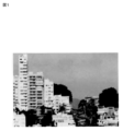
- FIG. 1 is a view showing an example of a display image. It is also a display image used to generate corrected image data according to the first embodiment of the present invention.
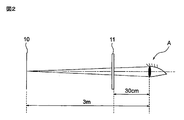
- FIG. 2 is a view showing a focal position of a presbyopic observer and a visual distance at which the image shown in FIG. 1 is arranged.
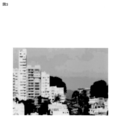
- FIG. 3 is a view showing a defocus image seen by the observer with presbyopia shown in FIG. 2 when the image shown in FIG.
- FIG. 4 is a view showing an image seen when a presbyopic observer shown in FIG. 2 looks at the pre-corrected image generated by the winner filter based on the image shown in FIG. The defocus is corrected and in focus, and the image is the same as in FIG. FIG.
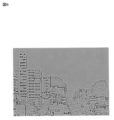
- FIG. 5 is a diagram showing an amplitude component of the pre-corrected image generated by the winner filter based on the image shown in FIG.
- FIG. 6 is a diagram also showing phase components of the pre-corrected image. The phase component is represented by shading.
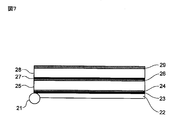
- FIG. 7 is a side view showing the structure of a liquid crystal device capable of simultaneously displaying an amplitude component and a phase component.
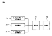
- FIG. 8 is a block diagram showing a configuration of a control system of the liquid crystal device shown in FIG.
- FIG. 9 is a conceptual view showing a state in which coherent imaging is established.
- FIG. 10 is a conceptual view showing a configuration provided with a scattering plate.
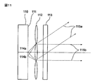
- FIG. 11 is a view showing the configuration of a display device according to the second embodiment.
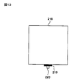
- FIG. 12 is a front view showing the configuration of the display device according to the third embodiment.
- FIG. 13 is a side view showing the configuration of the display device according to the third embodiment.
- x and y are two-dimensional coordinates of the image.
- I (x, y)
- O (x, y) the intensity of an image (hereinafter, display image) displayed on the display device
- O (x, y) and the amplitude of the display image is o (x, y)
- O (x, y) is Be done.
- O (x, y)
- a point image response function (hereinafter, IRF, amplitude) of the eye optical system is h (x, y)
- coherent imaging is expressed by convolution of the following equation (1).
- I (x, y)
- 2
- i (x, y), h (x, y) and o (x, y) are respectively expressed by the following equations (2), (3) and (4) by Fourier transformation.
- Fi (u, v), Fh (u, v), and Fo (u, v) are Fourier transforms of i (x, y), h (x, y), o (x, y), respectively.
- Fh (u, v) is a Fourier transform of IRF, which is also CTF (coherent transfer function).
- Fi (u, v) can be expressed by the product of Fh (u, v) and Fo (u, v) as shown in equation (5).
- Fi (u, v) Fh (u, v) Fo (u, v) (5)
- a is the pupil radius of the optical system
- ⁇ is the wavelength
- f is the focal length of the optical system
- w (u, v) is wavefront aberration.
- the pupil function including defocus as described above is a complex number and includes phase information.
- CTF is a Fourier transform of IRF.
- imaging is represented by the following equation (8) in the spatial frequency domain.
- Fi (u, v) Fh (u, v) Fo (u, v) (8)
- the correction represented by the following equation (9) that is, the correction with the pupil function h (u, v) including defocus on the display image (amplitude) o (u, v)
- the pre-correction image o '(x, y) is generated.
- the winner filter is expressed by the following equation (11).
- ⁇ is a signal noise ratio.
- the pre-corrected image o ′ ′ (u, v) is easily obtained by the inverse Fourier transform of the following equation (12).
- Fo "(u, v) t (u, v) Fo (u, v) (12)
- the data of the pre-corrected image o ′ ′ (u, v) is a complex number.
- the absolute value of the complex number indicates the amplitude component, and the argument indicates the phase component.
- FIG. 1 is a diagram showing an example of a display image.
- FIG. 2 is a view showing a focal position of a presbyopic observer and a visual distance at which the image shown in FIG. 1 is arranged.
- FIG. 3 is a view showing a defocused image seen by the observer of the presbyopia shown in FIG. 2 when the image shown in FIG. 1 is set at the clear vision distance. That is, when the presbyopia observer A (the focal point position 10 (FIG. 2)) which is focused only at 3 m or more looks at the display image 11 of FIG. 1 placed at a 30 cm clear vision distance (FIG. 2) It is. It turns out that it is blurred.
- FIG. 2 is a view showing a focal position of a presbyopic observer and a visual distance at which the image shown in FIG. 1 is arranged.
- FIG. 3 is a view showing a defocused image seen by the observer of the presbyopia shown in FIG. 2 when the image shown in FIG
- FIG. 4 is a view showing an image as viewed by an observer of the pre-corrected image presbyopia generated by the winner filter based on the image shown in FIG. It can be seen that the blur is well corrected. By looking at the pre-corrected image, even a presbyopic observer who is not focused on the clear vision distance can see an in-focus image.
- the data of the pre-corrected image generated by the winner filter is a complex number, and it is necessary to simultaneously display both the amplitude information and the phase information for accurate display. Hereinafter, display of amplitude information and phase information will be described.
- FIG. 5 is a diagram showing an example of the amplitude component of the pre-corrected image.
- FIG. 5 is a diagram showing an example of the amplitude component of the pre-corrected image.
- FIG. 6 is a diagram showing an example of the phase component of the pre-corrected image. However, the phase is displayed in gray scale.
- FIG. 7 is a side view showing the structure of a liquid crystal device capable of simultaneously displaying an amplitude component and a phase component.
- FIG. 8 is a block diagram showing a configuration of a control system of the liquid crystal device shown in FIG.
- the liquid crystal device shown in FIG. 7 includes a light source 21, a light guide plate 22, a polarizing plate 23, a switch array transparent electrode 24, a liquid crystal 25, a transparent electrode 26, a polarizing plate 27, a liquid crystal 28 and a switch array transparent electrode 29.
- the light guide plate 22 to the switch array transparent electrode 29 are stacked in this order.
- color filters for color display are omitted.
- the switch array transparent electrode 24, the transparent electrode 26, and the switch array transparent electrode 29 are connected to the control unit 15, and the control unit 15 is connected to the processing unit 16.
- the processing unit 16 generates corrected image data including the amplitude information and the phase information according to the above-described procedure.
- the amplitude information and the phase information of the corrected image data generated by the processing unit 16 are controlled by the control unit 15 and displayed on the liquid crystal device (display unit) shown in FIG.
- the light from the light source 21 passes through the light guide plate 22, is linearly polarized by the polarizing plate 23, and is incident on the liquid crystal 25.
- the switch array transparent electrode 24 When an electric field is applied between the switch array transparent electrode 24 and the transparent electrode 26, the polarization direction of the light whose alignment of the liquid crystal 25 is aligned in the direction of the voltage changes. Thus, the amount of light passing through the polarizer 27 is modulated by the applied electric field.
- the switch array transparent electrode 24 can control an electric field applied to each pixel, thereby displaying amplitude information.
- the light emitted from the polarizing plate 27 enters the liquid crystal 28.
- the liquid crystal 28 is oriented such that the effective refractive index changes with voltage, and the voltage applied to the switch array transparent electrode 29 can modulate the phase of the transmitted light. Therefore, phase information can be displayed.
- FIG. 9 is a conceptual view showing a state in which coherent imaging is established.
- the light 33 emitted from the point light source 31 becomes approximately parallel light by the lens 32, and passes through the display device 34 capable of displaying amplitude information and phase information
- the eyes of the observer A may be entered.
- the scattering plate 45 diffusing plate
- FIG. 10 is a conceptual view showing a configuration provided with a scattering plate.
- the light from the light source 46 is scattered at each point (for example, points 47a, 47b, 47c) of the scattering plate 45.
- the luminous fluxes 48a, 48b, 48c generated by the scattering at the scattering points 47a, 47b, 47c respectively pass through the display device 44 capable of displaying amplitude information and phase information.
- the observer can observe the information of the display device 44 from each of the directions A1, A2, and A3.
- the corrected image data generation method and the display apparatus display the pre-corrected image data including the amplitude information and the phase information on the display device 44 as the display unit, so that even a person who does not focus on the display position You can see the display in focus.
- the method and the display device for generating corrected image data according to the present embodiment even a person with a presbyopia can see a focused display without putting on or taking off the reading glasses.
- the burden on the eye of the observer with presbyopia can be alleviated, and observation can be performed without adding reading glasses or other optical members.
- FIG. 11 is a diagram showing the configuration of a display device according to the second embodiment. The display device shown in FIG.
- a pinhole array 111 is provided on one side of the light guide plate 110.
- the pinhole array 111 is configured, for example, by arranging pinholes 114 a and 114 b with a diameter of 5 ⁇ m at intervals of 10 ⁇ m.
- a microlens array 112 is provided at a position facing the pinhole array 111. The distance between the pinhole array 111 and the microlens array 112 is, for example, 1 mm.
- the diameter of the lenses constituting the microlens array 112 corresponds to a coherent illumination area, and is preferably, for example, 1 mm or more.
- a display device 113 is provided at a position facing the microlens array 112.
- the display device 113 is disposed, for example, at a position about 1 mm away from the microlens array 112, and displays amplitude information and phase information.
- a display unit, a control unit, and a processing unit shown in FIGS. 7 and 8 are used as the display device 113.
- the light scattered by the pinholes 114a and 114b becomes luminous fluxes 115a and 115b and is observed by the observer.
- the wavefronts of point light sources formed by the pinholes 114a and 114b become coherent illumination on the display device 113, so that coherent imaging can be obtained and recognition can be performed at a wide viewing angle.
- a solid light source particularly an LED
- red, green and blue LEDs for color display.
- the second embodiment is an example of a method of forming a coherence region.
- Third Embodiment Since an ordinary light source is an incoherent light source, it is necessary to create conditions for coherent imaging using an arrangement such as the point light source 31 of FIG. 9 or the pinholes 114a and 114b of FIG.
- a coherent light source such as a LD (laser diode)
- LD laser diode
- the light scattered at each of the scattering points 47a, 47b, 47c is coherent with each other and causes interference. This point is different from the second embodiment.
- speckle a granular pattern with high contrast
- FIG. 12 is a front view showing the configuration of the display device according to the third embodiment.
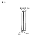
- FIG. 13 is a side view showing the configuration of the display device according to the third embodiment.
- the display shown in FIGS. 12 and 13 is an example using a laser such as an LD having a long coherence length.
- the display device illustrated in FIGS. 12 and 13 includes a display device 216, a scattering plate 217 (a diffusion plate), a light guide plate 218, a deflector 219 (AOD), and an LD 220.
- the laser light generated by the LD 220 is deflected by the deflector 219 and emitted to the display device 216 capable of displaying the amplitude and the phase via the light guide plate 218 and the scattering plate 217.
- the light generated by the LD 220 can be uniformly spread by the light guide plate 218, and the display plate 216 can be uniformly illuminated by the diffusion plate 217.
- the light generated by the LD 220 has coherence because it has a long coherence length. For this reason, it is easy to produce the speckle noise of a granular pattern. If speckle noise occurs, the information displayed on the display device 216 is significantly disturbed.
- the deflector 219 is used as a speckle reduction mechanism to deflect the laser beam of the illumination light to change the optical path length. This allows the speckle pattern to move and be averaged. Besides this, a method of shifting the wavelength of the LD is also effective for removing speckle noise. Thus, it is preferable to have a function to reduce speckle. For color display, red, green and blue LDs are used.
- the method of generating corrected image data and the display device according to the present invention are useful for mobile devices such as mobile phones, digital cameras, electronic books and the like provided with an FPD.
Abstract
Disclosed are a display device and a method for generating corrected image data whereby it is possible to display a pre-corrected image wherein vision accommodation for presbyopia or the like can be performed at a level sufficient for practical use. In the method for generating corrected image data, pre-corrected image data comprising amplitude information and phase information are generated. The display device has: a processing unit that generates corrected image data comprising amplitude information and phase information by means of a predetermined method for generating corrected image data; and a display unit that controls and displays the amplitude information and phase information of the generated corrected image data.
Description
本発明は、補正画像データ生成方法及び表示装置に関する。
The present invention relates to a method of generating corrected image data and a display device.
映像や文字を表示する表示装置(ディスプレイ)として、液晶ディスプレイやプラズマディスプレイがある。しかし、これらの表示装置は視度の調節が出来ない。高齢化社会の進展に伴って老眼(老視)の高齢者が増えており、視度調節が可能な表示装置、特にフラットパネルディスプレイ(FPD)が望まれている。特に携帯電話の普及やデジタルカメラの普及により、屋外でFPDによる表示を見る機会が増えている。
しかし、携帯電話やデジタルカメラのFPDを見るときに、いちいち老眼鏡を掛けるのは非常に煩わしい。デジタル一眼レフカメラには、ライブビューモニターとしてFPDが用いられているが、このデジタル一眼レフカメラにおいて、遠方の被写体を見つつ、ライブビューモニターを見るのに、いちいち老眼鏡を掛けたり外したりするのは、実際的ではない。それ以外でも、パソコンの液晶画面もいちいち老眼鏡を掛けるのは煩わしい。
従来、このような問題を解決するFPDは存在していなかった。これに対して、最近ではこのような問題は指摘されつつあり、特許文献1には、エッジ強調をした補正画像を表示する方法が提案されている。また、特許文献2にはテプリッツ行列の逆行列で生成した事前補正画像を用いる方法が提案されている。 As display devices (displays) for displaying images and characters, there are liquid crystal displays and plasma displays. However, these displays can not adjust the diopter. With the progress of the aging society, elderly people with presbyopia (presbyopia) are increasing, and display devices capable of adjusting the diopter, in particular, flat panel displays (FPDs) are desired. In particular, with the spread of mobile phones and the spread of digital cameras, the opportunity to view the display by FPD outdoors has increased.
However, when looking at FPDs of mobile phones and digital cameras, it is very bothersome to wear reading glasses. Although FPD is used as a live view monitor for digital single-lens reflex cameras, in this digital single-lens reflex camera, while looking at an object in the distance, the user wears or removes glasses to look at the live view monitor. Is not practical. Apart from that, it is too bothersome to wear glasses on the LCD screen of a personal computer.
Conventionally, there has been no FPD that solves such a problem. On the other hand, these problems are being pointed out recently, and Patent Document 1 proposes a method of displaying a corrected image with edge emphasis. Further, Patent Document 2 proposes a method of using a pre-corrected image generated by the inverse matrix of the Toeplitz matrix.
しかしながら、特許文献1によるエッジ強調の手法では、表示情報を多少見易くはするものの、デフォーカス像を鮮鋭な像に回復することは不可能である。特許文献1におけるエッジ強調は、像がボケる原因、すなわちデフォーカスの情報を用いた補正ではないためである。
一方、特許文献2では、デフォーカスの情報を用いた補正を行っている。眼の焦点調節不足(デフォーカス)による点広がり関数からなるテプリッツ行列に基づいて画像を補正している。しかし、テプリッツ行列を用いた場合は補正した画像データに複素数は生じないので、その補正の結果は、特許文献1と同じエッジ強調程度に留まり、実際に使用した場合の効果は実用レベルに至っているとは言えなかった。
本発明は、上記問題点に鑑みて考案したもので、視度調節を実用上十分なレベルで行うことのできる事前補正画像を生成する補正画像データ生成方法、及び事前補正画像を表示する表示装置を提供することを目的とする。 However, although the method of edge enhancement according to Patent Document 1 makes the display information somewhat easy to read, it is impossible to restore the defocus image to a sharp image. This is because the edge emphasis in Patent Document 1 is not a cause of blurring of the image, that is, a correction using defocus information.
On the other hand, in Patent Document 2, correction is performed using defocus information. The image is corrected based on the Toeplitz matrix consisting of point spread functions due to lack of focus adjustment (defocus) of the eye. However, since the complex number is not generated in the corrected image data when using the Toeplitz matrix, the result of the correction remains at the same level of edge enhancement as in Patent Document 1, and the effect when actually used reaches the practical level. I could not say that.
The present invention was devised in view of the above problems, and a corrected image data generating method for generating a pre-corrected image capable of performing diopter adjustment at a practically sufficient level, and a display device displaying the pre-corrected image Intended to provide.
上述した課題を解決し、目的を達成するために、本発明に係る補正画像データ生成方法は、振幅情報と位相情報とからなる事前補正画像データを生成することを特徴としている。
本発明の補正画像データ生成方法において、事前補正画像データを生成するために用いる補正関数は、光学系の補正関数であることが好ましい。
本発明の補正画像データ生成方法において、補正関数はデフォーカスの伝達関数の逆数であることが好ましい。
本発明の補正画像データ生成方法において、補正関数はデフォーカスの伝達関数のウイナフィルタであることが好ましい。
本発明の補正画像データ生成方法において、光学系は眼光学系であることが好ましい。
本発明に係る表示装置は、上述のいずれか一つの補正画像データ生成方法により、振幅情報と位相情報とからなる補正画像データを生成する処理部と、生成された補正画像データの振幅情報と位相情報とを制御して表示する表示部と、を有することを特徴としている。
本発明の表示装置において、表示部は、液晶で構成された表示デバイスであることが好ましい。
本発明の表示装置において、表示デバイスが散乱板を介して照明されることが好ましい。
本発明の表示装置において、コヒーレンス照明領域が1mmより大きいことが好ましい。
本発明の表示装置において、表示デバイスの光源が固体光源であることが好ましい。
本発明の表示装置において、光源はLEDであることが好ましい。
本発明の表示装置において、光源はレーザであることが好ましい。
本発明の表示装置において、スペックルを低減させるためのスペックル減少機構を有することが好ましい。 In order to solve the problems described above and achieve the object, a method of generating corrected image data according to the present invention is characterized by generating pre-corrected image data consisting of amplitude information and phase information.
In the method of generating corrected image data according to the present invention, the correction function used to generate the pre-corrected image data is preferably a correction function of an optical system.
In the method of generating corrected image data according to the present invention, the correction function is preferably an inverse of the transfer function of defocus.
In the method of generating corrected image data according to the present invention, the correction function is preferably a Wiener filter of a transfer function of defocus.
In the method of generating corrected image data according to the present invention, the optical system is preferably an eye optical system.
A display device according to the present invention includes a processing unit that generates correction image data including amplitude information and phase information according to any one of the above-described correction image data generation methods, and amplitude information and phase of the generated correction image data. And a display unit configured to control and display information.
In the display device of the present invention, the display unit is preferably a display device configured of liquid crystal.
In the display device of the present invention, the display device is preferably illuminated through the scattering plate.
In the display device of the present invention, the coherence illumination area is preferably larger than 1 mm.
In the display device of the present invention, the light source of the display device is preferably a solid light source.
In the display device of the present invention, the light source is preferably an LED.
In the display device of the present invention, the light source is preferably a laser.
In the display device of the present invention, it is preferable to have a speckle reduction mechanism for reducing speckle.
本発明に係る補正画像データ生成方法及び表示装置は、視度調節を実用上十分なレベルで行うことのできる事前補正画像を生成すると共に、その事前補正画像を表示できる、という効果を奏する。
The corrected image data generation method and the display apparatus according to the present invention have an effect of generating a pre-corrected image capable of performing diopter adjustment at a practically sufficient level and displaying the pre-corrected image.
図1は表示画像の例を示す図である。本発明の第1実施形態の補正画像データの生成に用いる表示画像でもある。
図2は老眼の観察者の焦点位置と図1に示す画像を配置した明視距離とを示す図である。
図3は図1に示す画像を明視距離においたときに図2に示す老眼の観察者が見るデフォーカス像を示す図である。
図4は図1に示す画像に基づいてウイナフィルタによって生成した事前補正画像を図2に示す老眼の観察者が見たときに見える像を示す図である。デフォーカスが補正され焦点が合っており、図1と同等の画像となっている。
図5は図1に示す画像に基づいてウイナフィルタによって生成した事前補正画像の振幅成分を示す図である。
図6は同じく事前補正画像の位相成分を示す図である。位相成分を濃淡で表している。
図7は振幅成分と位相成分を同時に表示できる液晶デバイスの構造を示す側面図である。
図8は図7に示す液晶デバイスの制御系の構成を示すブロック図である。
図9はコヒーレント結像が成立する状況を示す概念図である。
図10は散乱板を備えた構成を示す概念図である。
図11は第2実施形態に係る表示装置の構成を示す図である。
図12は第3実施形態に係る表示装置の構成を示す正面図である。
図13は第3実施形態に係る表示装置の構成を示す側面図である。 FIG. 1 is a view showing an example of a display image. It is also a display image used to generate corrected image data according to the first embodiment of the present invention.
FIG. 2 is a view showing a focal position of a presbyopic observer and a visual distance at which the image shown in FIG. 1 is arranged.
FIG. 3 is a view showing a defocus image seen by the observer with presbyopia shown in FIG. 2 when the image shown in FIG.
FIG. 4 is a view showing an image seen when a presbyopic observer shown in FIG. 2 looks at the pre-corrected image generated by the winner filter based on the image shown in FIG. The defocus is corrected and in focus, and the image is the same as in FIG.
FIG. 5 is a diagram showing an amplitude component of the pre-corrected image generated by the winner filter based on the image shown in FIG.
FIG. 6 is a diagram also showing phase components of the pre-corrected image. The phase component is represented by shading.
FIG. 7 is a side view showing the structure of a liquid crystal device capable of simultaneously displaying an amplitude component and a phase component.
FIG. 8 is a block diagram showing a configuration of a control system of the liquid crystal device shown in FIG.
FIG. 9 is a conceptual view showing a state in which coherent imaging is established.
FIG. 10 is a conceptual view showing a configuration provided with a scattering plate.
FIG. 11 is a view showing the configuration of a display device according to the second embodiment.
FIG. 12 is a front view showing the configuration of the display device according to the third embodiment.
FIG. 13 is a side view showing the configuration of the display device according to the third embodiment.
以下に、本発明に係る補正画像データ生成方法及び表示装置の実施形態を図面に基づいて詳細に説明する。なお、以下の実施形態によりこの発明が限定されるものではない。また、以下の説明では、I(x,y)等のパラメータに関して異なる表記(斜体と標準体(斜体でない))を用いているが、パラメータの意味は同じである。
(第1実施形態)
まず、事前補正画像の生成について説明する。
眼で観察される像(以下、観察像)の強度をI(x,y)、観察像の振幅をi(x,y)とすると、I(x,y)は、次のように表される。ここで、x、yは画像の2次元座標である。
I(x,y)=|i(x,y)|2
また、表示装置に表示する画像(以下、表示画像)の強度をO(x,y)、表示画像の振幅をo(x,y)とすると、O(x,y)は次のように表される。
O(x,y)=|o(x,y)|2
さらに、眼光学系の点像応答関数(以下、IRF、振幅)をh(x,y)とすると、コヒーレント結像は、次式(1)のコンボリューション(畳み込み)で表される。
 なお、観察像は強度(振幅の二乗)であるので、
I(x,y)=|i(x,y)|2=|h(x,y)*o(x,y)|2
となる。
ここで、i(x,y)、h(x,y)、o(x,y)は、それぞれ、フーリエ変換によって、次式(2)、(3)、(4)で表される。Fi(u,v)、Fh(u,v)、Fo(u,v)は、それぞれ、i(x,y)、h(x,y)、o(x,y)のフーリエ変換である。また、Fh(u,v)はIRFのフーリエ変換であるが、これはCTF(コヒーレント伝達関数)でもある。

 すると、Fi(u,v)は式(5)で示すように、Fh(u,v)とFo(u,v)の積で表すことができる。
Fi(u,v)=Fh(u,v)Fo(u,v) ・・・(5)
ところで、観察者が高齢者だと、老眼(老視)のために、観察者は表示画像にピントを合わすことが困難となることがある。このような場合、観察像はデフォーカスした状態の像となる。これは、光学系(眼)の瞳関数が波面収差、ここではデフォーカスを含んでいることを指す。
瞳関数がデフォーカス(波面収差)を含む場合、その瞳関数は次式(6)で表される。
 ここで、aは光学系の瞳半径、λは波長、fは光学系の焦点距離、w(u,v)は波面収差である。また、
 である。なお、このようにデフォーカスを含む瞳関数は複素数となり、位相情報を含んでいる。
さて、上記のように、CTFはIRFをフーリエ変換したものである。その一方で、CTFは、瞳関数そのものでもある。よって、上記式(6)において、p(u,v)をFh(u,v)に置き換えることができる。
また、
w(u,v)=(u2+v2)Δz/2f2
より、次式(7)が成り立つ。
 上記のように、式(5)より、結像は空間周波数領域で、次式(8)で表される。
Fi(u,v)=Fh(u,v)Fo(u,v) ・・・(8)
上記式(8)において、瞳関数Fh(u,v)がデフォーカスを含んでいる場合、観察像はデフォーカスした状態の像となる。そこで、本実施形態では、次式(9)で表される補正、すなわち、表示画像(振幅)o(u,v)に対してデフォーカスを含んだ瞳関数h(u,v)で補正を行い、事前補正画像o’(x,y)を生成する。
Fo’(u,v)=Fo(u,v)/Fh(u,v) ・・・(9)
o’(x,y)はFo’(u,v)の逆フーリエ変換で求められる。また、o’(x,y)は複素数で、絶対値が振幅で、アーギュメントが位相である。
この事前補正画像o’(x,y)を用いると、i’(x,y)は次式(10)で表される。
Fi’(u,v)=Fh(u,v)Fo’(u,v)
=Fh(u,v)Fo(u,v)/Fh(u,v)
=Fo(u,v) ・・・(10)
次式(10)から明らかなように、観察像i’(x,y)は、表示画像O(x,y)=|o(x,y)|2となるので、波面収差がない(例えば、デフォーカスしていない)時と同じ像が得られる。
このように、本実施形態では、表示画像をデフォーカスのコヒーレント伝達関数の逆数で補正することにより、視度調節を可能にする事前補正画像を作ることが出来る。
しかし、単純にCTF(コヒーレント伝達関数)で原画像(表示画像)を除すると雑音(ノイズ)が増大して、かえって回復像が劣化する場合がある。その場合には、ウイナフィルタを用いることが好ましい。ウイナフィルタは、次式(11)で表される。
 ここで、φは信号雑音比である。
事前補正画像o”(u,v)は、次式(12)の逆フーリエ変換で容易に求められる。
Fo”(u,v)=t(u,v)Fo(u,v) ・・・(12)
なお、この事前補正画像o”(u,v)のデータは複素数となる。その複素数の絶対値が振幅成分をアーギュメントが位相成分を表す。
次に、補正画像データ生成方法及び表示装置について、より具体的に説明する。
図1は、表示画像の例を示す図である。図2は、老眼の観察者の焦点位置と図1に示す画像を配置した明視距離とを示す図である。図3は、図1に示す画像を明視距離においたときに図2に示す老眼の観察者が見るデフォーカス像を示す図である。すなわち、3m以遠しか焦点の合わない老眼の観察者A(焦点位置10(図2))が、30cmの明視距離に置かれた図1の表示画像11を見たとき(図2)の像である。ボケていることがわかる。図4は、図1に示す画像に基づいてウイナフィルタによって生成した事前補正画像老眼の観察者が見たときの像を示す図である。良好にボケが補正されていることが分かる。事前補正画像を見ることによって明視距離に焦点の合わない老眼の観察者でも、焦点の合った像を見ることが出来る。
ウイナフィルタで生成された事前補正画像のデータは複素数であり、正確に表示するには、振幅情報と位相情報の両方を同時に表示する必要がある。
以下、振幅情報と位相情報の表示について説明する。図5は、事前補正画像の振幅成分の例を示す図である。図6は、事前補正画像の位相成分の例を示す図である。但し、位相を濃淡で表示している。図7は、振幅成分と位相成分を同時に表示できる液晶デバイスの構造を示す側面図である。図8は、図7に示す液晶デバイスの制御系の構成を示すブロック図である。
図7に示す液晶デバイスは、光源21、導光板22、偏光板23、スイッチアレイ透明電極24、液晶25、透明電極26、偏光板27、液晶28、スイッチアレイ透明電極29で構成されている。導光板22からスイッチアレイ透明電極29はこの順序で積層されている。なお、図7では、カラー表示用のカラーフィルターは省略してある。
また、図8に示すように、スイッチアレイ透明電極24、透明電極26、及びスイッチアレイ透明電極29は、制御部15に接続され、制御部15は処理部16に接続されている。
処理部16は、上述の手順により、振幅情報と位相情報とからなる補正画像データを生成する。処理部16によって生成された補正画像データの振幅情報と位相情報は制御部15によって制御され、図7に示す液晶デバイス(表示部)に表示される。
光源21からの光は導光板22を通って、偏光板23によって直線偏光となり液晶25に入射する。スイッチアレイ透明電極24と透明電極26の間に電界が加わると、液晶25の配向が電圧の方向にそろい光の偏光方向が変化する。従って、偏光板27を通過する光の量が、印加された電界によって変調される。スイッチアレイ透明電極24は画素毎に印加する電界を制御でき、そのことによって振幅情報を表示することが出来る。
偏光板27を出た光は液晶28に入射する。この液晶28は、電圧によって実効的屈折率が変化するように配向されており、スイッチアレイ透明電極29に印加される電圧によって透過する光の位相を変調することができる。従って位相情報を表示できる。スイッチアレイ透明電極24、29はそれぞれ画素毎に印加する電界を制御でき、透明電極26は、スイッチアレイ透明電極24、29に共通の電極となっている。このように簡単な構成で、振幅情報と位相情報を同時に表示できる。
図9は、コヒーレント結像が成立する状況を示す概念図である。
コヒーレント結像が成立する状況としては、図9に示すように、点光源31からの出射光33はレンズ32によって概略平行光になり、振幅情報と位相情報を表示できる表示デバイス34を通過して観察者Aの眼に入る場合が考えられる。しかし、この場合、観察者Aの見る方向が限定されるため、図10に示す散乱板45(拡散板)を用いることが望ましい。
図10は、散乱板を備えた構成を示す概念図である。
図10に示す構成では、光源46からの光は、散乱板45の各点(例えば点47a、47b、47c)で散乱する。散乱点47a、47b、47cにおける散乱によって生じた光束48a、48b、48cは、振幅情報と位相情報を表示できる表示デバイス44をそれぞれ通過する。このような構成により、観察者は、A1、A2、A3の各方向から、表示デバイス44の情報を観察することが出来る。
本実施形態に係る補正画像データ生成方法及び表示装置は、振幅情報と位相情報からなる事前補正画像データを、表示部としての表示デバイス44に表示することにより、表示位置に焦点の合わない人でも焦点の合った表示を見ることが出来る。
また、本実施形態の補正画像データ生成方法及び表示装置においては、老眼の人でも老眼鏡を掛けたり、外したりすることなく、焦点の合った表示を見ることが出来る。
さらに、本実施形態の補正画像データ生成方法及び表示装置によれば、老眼の観察者の眼の負担を軽減し、老眼鏡その他の光学部材を追加することなく観察することができる。また、観察者の視力に合わせた視度調節が可能なフラットパネルディスプレイ(FPD)を実現できる。
(第2実施形態)
眼の瞳径は、通常2~3mm程度であり、一点の情報は、表示デバイス上の直径1.8mm~2.7mmの範囲に表示されていると考えられる(図2参照)。従って、表示バイスに表示される振幅情報と位相情報のコヒーレント結像はその範囲で起これば十分である。あるいは、その半分程度でも十分な効果が認められる。従って、コヒーレント照明領域は1mm以上が好ましい。
図11は、第2実施形態に係る表示装置の構成を示す図である。図11に示す表示装置は、導光板110、ピンホールアレイ111、マイクロレンズアレイ112、及び表示デバイス113を備え、任意のコヒーレント照明領域を生成する。
導光板110の片面には、ピンホールアレイ111が設けられている。ピンホールアレイ111は、例えば、直径5μmのピンホール114a、114bを10μm間隔に配置することで構成されている。
ピンホールアレイ111に対向した位置には、マイクロレンズアレイ112が設けられている。ピンホールアレイ111とマイクロレンズアレイ112との間隔は、例えば1mmである。マイクロレンズアレイ112のを構成するレンズの径は、コヒーレント照明領域に相当し、例えば1mm以上が好ましい。
更に、マイクロレンズアレイ112と対向する位置には、表示デバイス113が設けられている。表示デバイス113は、例えばマイクロレンズアレイ112から1mm程度離れた位置に配置され、振幅情報と位相情報を表示する。この表示デバイス113としては、例えば、図7及び図8に示す表示部、制御部、及び処理部を用いる。
図11に示す表示装置においては、ピンホール114a、114bで散乱された光は、光束115a、115bとなって観察者に観察される。ピンホール114a、114bで形成された点光源の波面は、表示デバイス113上でコヒーレント照明になるので、コヒーレント結像が得られ、且つ広い視野角で認識が出来る。
また、光源には固体光源、特にLEDを用いることが好ましい。カラー表示のために、赤、緑、青のLEDを用いるとよい。
なお、第2実施形態は、コヒーレンス領域を形成する方法の一例である。
(第3実施形態)
通常の光源はインコヒーレント光源であるため、図9の点光源31や図11のピンホール114a、114bのような構成を用いて、コヒーレント結像の条件を作り出す必要がある。これに対して、LD(レーザーダイオード)のようなコヒーレント光源の場合は、点光源と等価であり、コヒーレント結像の条件は作り易い。しかし、そのままでは図9のように一方向でしか観察できない。従って、図10のように散乱板45を用いるなどして、あらゆる方向から観察できる工夫が必要になる。但し、この場合に注意する必要があるのは、各散乱点47a、47b、47cで散乱される光が互いにコヒーレントであり干渉を生じる点である。この点は、第2実施形態とは異なる。散乱板45を用いた場合には、スペックルといわれるコントラストの強い粒状模様を生じるおそれがある。なお、光源のコヒーレント、インコヒーレントの違いと、結像におけるコヒーレント結像とインコヒーレント結像は別物であることに注意が必要である。
図12は、第3実施形態に係る表示装置の構成を示す正面図である。図13は、第3実施形態に係る表示装置の構成を示す側面図である。図12、図13に示す表示装置は、コヒーレンス長の長いLD等のレーザを用いた例である。
図12、図13に示す表示装置は、表示デバイス216、散乱板217(拡散板)、導光板218、偏向器219(AOD)、及びLD220を備える。
LD220で発生したレーザ光は、偏向器219で偏向され、導光板218と散乱板217を介して、振幅と位相を表示できる表示デバイス216に照射される。LD220で発生した光は導光板218で一様に広がり、更に拡散板217によって均一に表示デバイス216を照明することが出来る。
LD220で発生した光はコヒーレント長が長いため、コヒーレンスがある。このため、粒状模様のスペックルノイズを生じやすい。スペックルノイズが生じた場合には、表示デバイス216に表示する情報が著しく阻害される。スペックルノイズを除く為には、一般的には、散乱板を回転させるなどしてスペックル模様を平均化させ、実質的に見えなくすることが行われるが、薄型のフラットパネルディスプレイ(FPD)においては、散乱板を回転させることは実際的ではない。そこで、第3実施形態の表示装置では、スペックル減少機構として偏向器219を用いて照明光のレーザービームを偏向させて光路長を変化させている。これによって、スペックル模様は移動し、平均化させることが出来る。
この他、スペックルノイズ除去のためには、LDの波長をシフトする方法も効果がある。このように、スペックルを低減する機能を有することが好ましい。なお、カラー表示の為には、赤、緑、青のLDを用いる。 Hereinafter, embodiments of a method of generating corrected image data and a display device according to the present invention will be described in detail based on the drawings. Note that the present invention is not limited by the following embodiments. In the following description, different notations (italic letters and standard letters (non-italic letters)) are used for parameters such as I (x, y), but the meanings of the parameters are the same.
First Embodiment
First, generation of the pre-corrected image will be described.
Assuming that the intensity of an image observed by the eye (hereinafter referred to as an observation image) is I (x, y) and the amplitude of the observation image is i (x, y), I (x, y) is expressed as follows. Ru. Here, x and y are two-dimensional coordinates of the image.
I (x, y) = | i (x, y) | 2
Further, assuming that the intensity of an image (hereinafter, display image) displayed on the display device is O (x, y) and the amplitude of the display image is o (x, y), O (x, y) is Be done.
O (x, y) = | o (x, y) | 2
Further, assuming that a point image response function (hereinafter, IRF, amplitude) of the eye optical system is h (x, y), coherent imaging is expressed by convolution of the following equation (1).
Since the observation image is intensity (square of amplitude),
I (x, y) = | i (x, y) | 2 = | h (x, y) * o (x, y) | 2
It becomes.
Here, i (x, y), h (x, y) and o (x, y) are respectively expressed by the following equations (2), (3) and (4) by Fourier transformation. Fi (u, v), Fh (u, v), and Fo (u, v) are Fourier transforms of i (x, y), h (x, y), o (x, y), respectively. Also, Fh (u, v) is a Fourier transform of IRF, which is also CTF (coherent transfer function).
Then, Fi (u, v) can be expressed by the product of Fh (u, v) and Fo (u, v) as shown in equation (5).
Fi (u, v) = Fh (u, v) Fo (u, v) (5)
By the way, if the observer is an elderly person, it may be difficult for the observer to focus on the displayed image because of presbyopia (presbyopia). In such a case, the observation image is an image in a defocused state. This indicates that the pupil function of the optical system (eye) includes wavefront aberration, here defocus.
When the pupil function includes defocus (wavefront aberration), the pupil function is expressed by the following equation (6).
Here, a is the pupil radius of the optical system, λ is the wavelength, f is the focal length of the optical system, and w (u, v) is wavefront aberration. Also,
It is. Note that the pupil function including defocus as described above is a complex number and includes phase information.
Now, as described above, CTF is a Fourier transform of IRF. On the other hand, CTF is also the pupil function itself. Therefore, in the above equation (6), p (u, v) can be replaced with Fh (u, v).
Also,
w (u, v) = (u 2 + v 2 ) Δz / 2 f 2
Thus, the following equation (7) holds.
As described above, according to equation (5), imaging is represented by the following equation (8) in the spatial frequency domain.
Fi (u, v) = Fh (u, v) Fo (u, v) (8)
In the above equation (8), when the pupil function Fh (u, v) includes defocus, the observation image is an image in a defocused state. Therefore, in the present embodiment, the correction represented by the following equation (9), that is, the correction with the pupil function h (u, v) including defocus on the display image (amplitude) o (u, v) The pre-correction image o '(x, y) is generated.
Fo '(u, v) = Fo (u, v) / Fh (u, v) (9)
o '(x, y) is obtained by the inverse Fourier transform of Fo' (u, v). Also, o ′ (x, y) is a complex number, the absolute value is an amplitude, and the argument is a phase.
Using this pre-corrected image o ′ (x, y), i ′ (x, y) is expressed by the following equation (10).
Fi '(u, v) = Fh (u, v) Fo' (u, v)
= Fh (u, v) Fo (u, v) / Fh (u, v)
= Fo (u, v) (10)
As is apparent from equation (10), observation image i '(x, y) is the display image O (x, y) = | o (x, y) | Since 2 become, there is no wavefront aberration (e.g. (Not defocused) the same image is obtained.
As described above, in the present embodiment, by correcting the display image with the inverse of the coherent transfer function of defocus, it is possible to create a pre-corrected image that enables diopter adjustment.
However, if the original image (display image) is simply divided by CTF (coherent transfer function), noise may increase and the recovered image may deteriorate. In that case, it is preferable to use a Wiener filter. The winner filter is expressed by the following equation (11).
Here, φ is a signal noise ratio.
The pre-corrected image o ′ ′ (u, v) is easily obtained by the inverse Fourier transform of the following equation (12).
Fo "(u, v) = t (u, v) Fo (u, v) (12)
The data of the pre-corrected image o ′ ′ (u, v) is a complex number. The absolute value of the complex number indicates the amplitude component, and the argument indicates the phase component.
Next, the correction image data generation method and the display device will be described more specifically.
FIG. 1 is a diagram showing an example of a display image. FIG. 2 is a view showing a focal position of a presbyopic observer and a visual distance at which the image shown in FIG. 1 is arranged. FIG. 3 is a view showing a defocused image seen by the observer of the presbyopia shown in FIG. 2 when the image shown in FIG. 1 is set at the clear vision distance. That is, when the presbyopia observer A (the focal point position 10 (FIG. 2)) which is focused only at 3 m or more looks at thedisplay image 11 of FIG. 1 placed at a 30 cm clear vision distance (FIG. 2) It is. It turns out that it is blurred. FIG. 4 is a view showing an image as viewed by an observer of the pre-corrected image presbyopia generated by the winner filter based on the image shown in FIG. It can be seen that the blur is well corrected. By looking at the pre-corrected image, even a presbyopic observer who is not focused on the clear vision distance can see an in-focus image.
The data of the pre-corrected image generated by the winner filter is a complex number, and it is necessary to simultaneously display both the amplitude information and the phase information for accurate display.
Hereinafter, display of amplitude information and phase information will be described. FIG. 5 is a diagram showing an example of the amplitude component of the pre-corrected image. FIG. 6 is a diagram showing an example of the phase component of the pre-corrected image. However, the phase is displayed in gray scale. FIG. 7 is a side view showing the structure of a liquid crystal device capable of simultaneously displaying an amplitude component and a phase component. FIG. 8 is a block diagram showing a configuration of a control system of the liquid crystal device shown in FIG.
The liquid crystal device shown in FIG. 7 includes alight source 21, a light guide plate 22, a polarizing plate 23, a switch array transparent electrode 24, a liquid crystal 25, a transparent electrode 26, a polarizing plate 27, a liquid crystal 28 and a switch array transparent electrode 29. The light guide plate 22 to the switch array transparent electrode 29 are stacked in this order. In FIG. 7, color filters for color display are omitted.
Further, as shown in FIG. 8, the switch arraytransparent electrode 24, the transparent electrode 26, and the switch array transparent electrode 29 are connected to the control unit 15, and the control unit 15 is connected to the processing unit 16.
Theprocessing unit 16 generates corrected image data including the amplitude information and the phase information according to the above-described procedure. The amplitude information and the phase information of the corrected image data generated by the processing unit 16 are controlled by the control unit 15 and displayed on the liquid crystal device (display unit) shown in FIG.
The light from thelight source 21 passes through the light guide plate 22, is linearly polarized by the polarizing plate 23, and is incident on the liquid crystal 25. When an electric field is applied between the switch array transparent electrode 24 and the transparent electrode 26, the polarization direction of the light whose alignment of the liquid crystal 25 is aligned in the direction of the voltage changes. Thus, the amount of light passing through the polarizer 27 is modulated by the applied electric field. The switch array transparent electrode 24 can control an electric field applied to each pixel, thereby displaying amplitude information.
The light emitted from the polarizing plate 27 enters theliquid crystal 28. The liquid crystal 28 is oriented such that the effective refractive index changes with voltage, and the voltage applied to the switch array transparent electrode 29 can modulate the phase of the transmitted light. Therefore, phase information can be displayed. The switch array transparent electrodes 24 and 29 can control the electric field applied to each pixel, and the transparent electrode 26 is an electrode common to the switch array transparent electrodes 24 and 29. With such a simple configuration, amplitude information and phase information can be simultaneously displayed.
FIG. 9 is a conceptual view showing a state in which coherent imaging is established.
As a situation where coherent imaging is established, as shown in FIG. 9, the light 33 emitted from the pointlight source 31 becomes approximately parallel light by the lens 32, and passes through the display device 34 capable of displaying amplitude information and phase information It is conceivable that the eyes of the observer A may be entered. However, in this case, since the viewing direction of the observer A is limited, it is desirable to use the scattering plate 45 (diffusing plate) shown in FIG.
FIG. 10 is a conceptual view showing a configuration provided with a scattering plate.
In the configuration shown in FIG. 10, the light from thelight source 46 is scattered at each point (for example, points 47a, 47b, 47c) of the scattering plate 45. The luminous fluxes 48a, 48b, 48c generated by the scattering at the scattering points 47a, 47b, 47c respectively pass through the display device 44 capable of displaying amplitude information and phase information. With such a configuration, the observer can observe the information of the display device 44 from each of the directions A1, A2, and A3.
The corrected image data generation method and the display apparatus according to the present embodiment display the pre-corrected image data including the amplitude information and the phase information on thedisplay device 44 as the display unit, so that even a person who does not focus on the display position You can see the display in focus.
Further, in the method and the display device for generating corrected image data according to the present embodiment, even a person with a presbyopia can see a focused display without putting on or taking off the reading glasses.
Furthermore, according to the method of generating corrected image data and the display device of the present embodiment, the burden on the eye of the observer with presbyopia can be alleviated, and observation can be performed without adding reading glasses or other optical members. Further, it is possible to realize a flat panel display (FPD) capable of adjusting the diopter according to the eyesight of the observer.
Second Embodiment
The pupil diameter of the eye is usually about 2 to 3 mm, and one-point information is considered to be displayed in the range of 1.8 mm to 2.7 mm in diameter on the display device (see FIG. 2). Therefore, coherent imaging of the amplitude and phase information displayed on the display device is sufficient if it occurs in that range. Alternatively, sufficient effects can be observed even at about half of that. Therefore, the coherent illumination area is preferably 1 mm or more.
FIG. 11 is a diagram showing the configuration of a display device according to the second embodiment. The display device shown in FIG. 11 includes alight guide plate 110, a pinhole array 111, a microlens array 112, and a display device 113, and generates an arbitrary coherent illumination area.
Apinhole array 111 is provided on one side of the light guide plate 110. The pinhole array 111 is configured, for example, by arranging pinholes 114 a and 114 b with a diameter of 5 μm at intervals of 10 μm.
Amicrolens array 112 is provided at a position facing the pinhole array 111. The distance between the pinhole array 111 and the microlens array 112 is, for example, 1 mm. The diameter of the lenses constituting the microlens array 112 corresponds to a coherent illumination area, and is preferably, for example, 1 mm or more.
Furthermore, adisplay device 113 is provided at a position facing the microlens array 112. The display device 113 is disposed, for example, at a position about 1 mm away from the microlens array 112, and displays amplitude information and phase information. As the display device 113, for example, a display unit, a control unit, and a processing unit shown in FIGS. 7 and 8 are used.
In the display device shown in FIG. 11, the light scattered by the pinholes 114a and 114b becomes luminous fluxes 115a and 115b and is observed by the observer. The wavefronts of point light sources formed by the pinholes 114a and 114b become coherent illumination on the display device 113, so that coherent imaging can be obtained and recognition can be performed at a wide viewing angle.
In addition, it is preferable to use a solid light source, particularly an LED, as the light source. It is good to use red, green and blue LEDs for color display.
The second embodiment is an example of a method of forming a coherence region.
Third Embodiment
Since an ordinary light source is an incoherent light source, it is necessary to create conditions for coherent imaging using an arrangement such as the pointlight source 31 of FIG. 9 or the pinholes 114a and 114b of FIG. On the other hand, in the case of a coherent light source such as a LD (laser diode), it is equivalent to a point light source, and conditions for coherent imaging are easy to make. However, as it is, it can be observed only in one direction as shown in FIG. Therefore, as shown in FIG. 10, it is necessary to use a scattering plate 45 so that the device can be observed from any direction. However, in this case, it should be noted that the light scattered at each of the scattering points 47a, 47b, 47c is coherent with each other and causes interference. This point is different from the second embodiment. When the scattering plate 45 is used, there is a possibility that a granular pattern with high contrast called speckle is generated. It should be noted that the difference between the coherent and incoherent light sources and that the coherent imaging and the incoherent imaging in imaging are different.
FIG. 12 is a front view showing the configuration of the display device according to the third embodiment. FIG. 13 is a side view showing the configuration of the display device according to the third embodiment. The display shown in FIGS. 12 and 13 is an example using a laser such as an LD having a long coherence length.
The display device illustrated in FIGS. 12 and 13 includes adisplay device 216, a scattering plate 217 (a diffusion plate), a light guide plate 218, a deflector 219 (AOD), and an LD 220.
The laser light generated by theLD 220 is deflected by the deflector 219 and emitted to the display device 216 capable of displaying the amplitude and the phase via the light guide plate 218 and the scattering plate 217. The light generated by the LD 220 can be uniformly spread by the light guide plate 218, and the display plate 216 can be uniformly illuminated by the diffusion plate 217.
The light generated by theLD 220 has coherence because it has a long coherence length. For this reason, it is easy to produce the speckle noise of a granular pattern. If speckle noise occurs, the information displayed on the display device 216 is significantly disturbed. In order to remove speckle noise, it is generally performed to average the speckle pattern by rotating a scattering plate or the like to substantially make the speckle pattern invisible. However, a thin flat panel display (FPD) In, it is not practical to rotate the scattering plate. Therefore, in the display device of the third embodiment, the deflector 219 is used as a speckle reduction mechanism to deflect the laser beam of the illumination light to change the optical path length. This allows the speckle pattern to move and be averaged.
Besides this, a method of shifting the wavelength of the LD is also effective for removing speckle noise. Thus, it is preferable to have a function to reduce speckle. For color display, red, green and blue LDs are used.
(第1実施形態)
まず、事前補正画像の生成について説明する。
眼で観察される像(以下、観察像)の強度をI(x,y)、観察像の振幅をi(x,y)とすると、I(x,y)は、次のように表される。ここで、x、yは画像の2次元座標である。
I(x,y)=|i(x,y)|2
また、表示装置に表示する画像(以下、表示画像)の強度をO(x,y)、表示画像の振幅をo(x,y)とすると、O(x,y)は次のように表される。
O(x,y)=|o(x,y)|2
さらに、眼光学系の点像応答関数(以下、IRF、振幅)をh(x,y)とすると、コヒーレント結像は、次式(1)のコンボリューション(畳み込み)で表される。
I(x,y)=|i(x,y)|2=|h(x,y)*o(x,y)|2
となる。
ここで、i(x,y)、h(x,y)、o(x,y)は、それぞれ、フーリエ変換によって、次式(2)、(3)、(4)で表される。Fi(u,v)、Fh(u,v)、Fo(u,v)は、それぞれ、i(x,y)、h(x,y)、o(x,y)のフーリエ変換である。また、Fh(u,v)はIRFのフーリエ変換であるが、これはCTF(コヒーレント伝達関数)でもある。
Fi(u,v)=Fh(u,v)Fo(u,v) ・・・(5)
ところで、観察者が高齢者だと、老眼(老視)のために、観察者は表示画像にピントを合わすことが困難となることがある。このような場合、観察像はデフォーカスした状態の像となる。これは、光学系(眼)の瞳関数が波面収差、ここではデフォーカスを含んでいることを指す。
瞳関数がデフォーカス(波面収差)を含む場合、その瞳関数は次式(6)で表される。
さて、上記のように、CTFはIRFをフーリエ変換したものである。その一方で、CTFは、瞳関数そのものでもある。よって、上記式(6)において、p(u,v)をFh(u,v)に置き換えることができる。
また、
w(u,v)=(u2+v2)Δz/2f2
より、次式(7)が成り立つ。
Fi(u,v)=Fh(u,v)Fo(u,v) ・・・(8)
上記式(8)において、瞳関数Fh(u,v)がデフォーカスを含んでいる場合、観察像はデフォーカスした状態の像となる。そこで、本実施形態では、次式(9)で表される補正、すなわち、表示画像(振幅)o(u,v)に対してデフォーカスを含んだ瞳関数h(u,v)で補正を行い、事前補正画像o’(x,y)を生成する。
Fo’(u,v)=Fo(u,v)/Fh(u,v) ・・・(9)
o’(x,y)はFo’(u,v)の逆フーリエ変換で求められる。また、o’(x,y)は複素数で、絶対値が振幅で、アーギュメントが位相である。
この事前補正画像o’(x,y)を用いると、i’(x,y)は次式(10)で表される。
Fi’(u,v)=Fh(u,v)Fo’(u,v)
=Fh(u,v)Fo(u,v)/Fh(u,v)
=Fo(u,v) ・・・(10)
次式(10)から明らかなように、観察像i’(x,y)は、表示画像O(x,y)=|o(x,y)|2となるので、波面収差がない(例えば、デフォーカスしていない)時と同じ像が得られる。
このように、本実施形態では、表示画像をデフォーカスのコヒーレント伝達関数の逆数で補正することにより、視度調節を可能にする事前補正画像を作ることが出来る。
しかし、単純にCTF(コヒーレント伝達関数)で原画像(表示画像)を除すると雑音(ノイズ)が増大して、かえって回復像が劣化する場合がある。その場合には、ウイナフィルタを用いることが好ましい。ウイナフィルタは、次式(11)で表される。
事前補正画像o”(u,v)は、次式(12)の逆フーリエ変換で容易に求められる。
Fo”(u,v)=t(u,v)Fo(u,v) ・・・(12)
なお、この事前補正画像o”(u,v)のデータは複素数となる。その複素数の絶対値が振幅成分をアーギュメントが位相成分を表す。
次に、補正画像データ生成方法及び表示装置について、より具体的に説明する。
図1は、表示画像の例を示す図である。図2は、老眼の観察者の焦点位置と図1に示す画像を配置した明視距離とを示す図である。図3は、図1に示す画像を明視距離においたときに図2に示す老眼の観察者が見るデフォーカス像を示す図である。すなわち、3m以遠しか焦点の合わない老眼の観察者A(焦点位置10(図2))が、30cmの明視距離に置かれた図1の表示画像11を見たとき(図2)の像である。ボケていることがわかる。図4は、図1に示す画像に基づいてウイナフィルタによって生成した事前補正画像老眼の観察者が見たときの像を示す図である。良好にボケが補正されていることが分かる。事前補正画像を見ることによって明視距離に焦点の合わない老眼の観察者でも、焦点の合った像を見ることが出来る。
ウイナフィルタで生成された事前補正画像のデータは複素数であり、正確に表示するには、振幅情報と位相情報の両方を同時に表示する必要がある。
以下、振幅情報と位相情報の表示について説明する。図5は、事前補正画像の振幅成分の例を示す図である。図6は、事前補正画像の位相成分の例を示す図である。但し、位相を濃淡で表示している。図7は、振幅成分と位相成分を同時に表示できる液晶デバイスの構造を示す側面図である。図8は、図7に示す液晶デバイスの制御系の構成を示すブロック図である。
図7に示す液晶デバイスは、光源21、導光板22、偏光板23、スイッチアレイ透明電極24、液晶25、透明電極26、偏光板27、液晶28、スイッチアレイ透明電極29で構成されている。導光板22からスイッチアレイ透明電極29はこの順序で積層されている。なお、図7では、カラー表示用のカラーフィルターは省略してある。
また、図8に示すように、スイッチアレイ透明電極24、透明電極26、及びスイッチアレイ透明電極29は、制御部15に接続され、制御部15は処理部16に接続されている。
処理部16は、上述の手順により、振幅情報と位相情報とからなる補正画像データを生成する。処理部16によって生成された補正画像データの振幅情報と位相情報は制御部15によって制御され、図7に示す液晶デバイス(表示部)に表示される。
光源21からの光は導光板22を通って、偏光板23によって直線偏光となり液晶25に入射する。スイッチアレイ透明電極24と透明電極26の間に電界が加わると、液晶25の配向が電圧の方向にそろい光の偏光方向が変化する。従って、偏光板27を通過する光の量が、印加された電界によって変調される。スイッチアレイ透明電極24は画素毎に印加する電界を制御でき、そのことによって振幅情報を表示することが出来る。
偏光板27を出た光は液晶28に入射する。この液晶28は、電圧によって実効的屈折率が変化するように配向されており、スイッチアレイ透明電極29に印加される電圧によって透過する光の位相を変調することができる。従って位相情報を表示できる。スイッチアレイ透明電極24、29はそれぞれ画素毎に印加する電界を制御でき、透明電極26は、スイッチアレイ透明電極24、29に共通の電極となっている。このように簡単な構成で、振幅情報と位相情報を同時に表示できる。
図9は、コヒーレント結像が成立する状況を示す概念図である。
コヒーレント結像が成立する状況としては、図9に示すように、点光源31からの出射光33はレンズ32によって概略平行光になり、振幅情報と位相情報を表示できる表示デバイス34を通過して観察者Aの眼に入る場合が考えられる。しかし、この場合、観察者Aの見る方向が限定されるため、図10に示す散乱板45(拡散板)を用いることが望ましい。
図10は、散乱板を備えた構成を示す概念図である。
図10に示す構成では、光源46からの光は、散乱板45の各点(例えば点47a、47b、47c)で散乱する。散乱点47a、47b、47cにおける散乱によって生じた光束48a、48b、48cは、振幅情報と位相情報を表示できる表示デバイス44をそれぞれ通過する。このような構成により、観察者は、A1、A2、A3の各方向から、表示デバイス44の情報を観察することが出来る。
本実施形態に係る補正画像データ生成方法及び表示装置は、振幅情報と位相情報からなる事前補正画像データを、表示部としての表示デバイス44に表示することにより、表示位置に焦点の合わない人でも焦点の合った表示を見ることが出来る。
また、本実施形態の補正画像データ生成方法及び表示装置においては、老眼の人でも老眼鏡を掛けたり、外したりすることなく、焦点の合った表示を見ることが出来る。
さらに、本実施形態の補正画像データ生成方法及び表示装置によれば、老眼の観察者の眼の負担を軽減し、老眼鏡その他の光学部材を追加することなく観察することができる。また、観察者の視力に合わせた視度調節が可能なフラットパネルディスプレイ(FPD)を実現できる。
(第2実施形態)
眼の瞳径は、通常2~3mm程度であり、一点の情報は、表示デバイス上の直径1.8mm~2.7mmの範囲に表示されていると考えられる(図2参照)。従って、表示バイスに表示される振幅情報と位相情報のコヒーレント結像はその範囲で起これば十分である。あるいは、その半分程度でも十分な効果が認められる。従って、コヒーレント照明領域は1mm以上が好ましい。
図11は、第2実施形態に係る表示装置の構成を示す図である。図11に示す表示装置は、導光板110、ピンホールアレイ111、マイクロレンズアレイ112、及び表示デバイス113を備え、任意のコヒーレント照明領域を生成する。
導光板110の片面には、ピンホールアレイ111が設けられている。ピンホールアレイ111は、例えば、直径5μmのピンホール114a、114bを10μm間隔に配置することで構成されている。
ピンホールアレイ111に対向した位置には、マイクロレンズアレイ112が設けられている。ピンホールアレイ111とマイクロレンズアレイ112との間隔は、例えば1mmである。マイクロレンズアレイ112のを構成するレンズの径は、コヒーレント照明領域に相当し、例えば1mm以上が好ましい。
更に、マイクロレンズアレイ112と対向する位置には、表示デバイス113が設けられている。表示デバイス113は、例えばマイクロレンズアレイ112から1mm程度離れた位置に配置され、振幅情報と位相情報を表示する。この表示デバイス113としては、例えば、図7及び図8に示す表示部、制御部、及び処理部を用いる。
図11に示す表示装置においては、ピンホール114a、114bで散乱された光は、光束115a、115bとなって観察者に観察される。ピンホール114a、114bで形成された点光源の波面は、表示デバイス113上でコヒーレント照明になるので、コヒーレント結像が得られ、且つ広い視野角で認識が出来る。
また、光源には固体光源、特にLEDを用いることが好ましい。カラー表示のために、赤、緑、青のLEDを用いるとよい。
なお、第2実施形態は、コヒーレンス領域を形成する方法の一例である。
(第3実施形態)
通常の光源はインコヒーレント光源であるため、図9の点光源31や図11のピンホール114a、114bのような構成を用いて、コヒーレント結像の条件を作り出す必要がある。これに対して、LD(レーザーダイオード)のようなコヒーレント光源の場合は、点光源と等価であり、コヒーレント結像の条件は作り易い。しかし、そのままでは図9のように一方向でしか観察できない。従って、図10のように散乱板45を用いるなどして、あらゆる方向から観察できる工夫が必要になる。但し、この場合に注意する必要があるのは、各散乱点47a、47b、47cで散乱される光が互いにコヒーレントであり干渉を生じる点である。この点は、第2実施形態とは異なる。散乱板45を用いた場合には、スペックルといわれるコントラストの強い粒状模様を生じるおそれがある。なお、光源のコヒーレント、インコヒーレントの違いと、結像におけるコヒーレント結像とインコヒーレント結像は別物であることに注意が必要である。
図12は、第3実施形態に係る表示装置の構成を示す正面図である。図13は、第3実施形態に係る表示装置の構成を示す側面図である。図12、図13に示す表示装置は、コヒーレンス長の長いLD等のレーザを用いた例である。
図12、図13に示す表示装置は、表示デバイス216、散乱板217(拡散板)、導光板218、偏向器219(AOD)、及びLD220を備える。
LD220で発生したレーザ光は、偏向器219で偏向され、導光板218と散乱板217を介して、振幅と位相を表示できる表示デバイス216に照射される。LD220で発生した光は導光板218で一様に広がり、更に拡散板217によって均一に表示デバイス216を照明することが出来る。
LD220で発生した光はコヒーレント長が長いため、コヒーレンスがある。このため、粒状模様のスペックルノイズを生じやすい。スペックルノイズが生じた場合には、表示デバイス216に表示する情報が著しく阻害される。スペックルノイズを除く為には、一般的には、散乱板を回転させるなどしてスペックル模様を平均化させ、実質的に見えなくすることが行われるが、薄型のフラットパネルディスプレイ(FPD)においては、散乱板を回転させることは実際的ではない。そこで、第3実施形態の表示装置では、スペックル減少機構として偏向器219を用いて照明光のレーザービームを偏向させて光路長を変化させている。これによって、スペックル模様は移動し、平均化させることが出来る。
この他、スペックルノイズ除去のためには、LDの波長をシフトする方法も効果がある。このように、スペックルを低減する機能を有することが好ましい。なお、カラー表示の為には、赤、緑、青のLDを用いる。 Hereinafter, embodiments of a method of generating corrected image data and a display device according to the present invention will be described in detail based on the drawings. Note that the present invention is not limited by the following embodiments. In the following description, different notations (italic letters and standard letters (non-italic letters)) are used for parameters such as I (x, y), but the meanings of the parameters are the same.
First Embodiment
First, generation of the pre-corrected image will be described.
Assuming that the intensity of an image observed by the eye (hereinafter referred to as an observation image) is I (x, y) and the amplitude of the observation image is i (x, y), I (x, y) is expressed as follows. Ru. Here, x and y are two-dimensional coordinates of the image.
I (x, y) = | i (x, y) | 2
Further, assuming that the intensity of an image (hereinafter, display image) displayed on the display device is O (x, y) and the amplitude of the display image is o (x, y), O (x, y) is Be done.
O (x, y) = | o (x, y) | 2
Further, assuming that a point image response function (hereinafter, IRF, amplitude) of the eye optical system is h (x, y), coherent imaging is expressed by convolution of the following equation (1).
I (x, y) = | i (x, y) | 2 = | h (x, y) * o (x, y) | 2
It becomes.
Here, i (x, y), h (x, y) and o (x, y) are respectively expressed by the following equations (2), (3) and (4) by Fourier transformation. Fi (u, v), Fh (u, v), and Fo (u, v) are Fourier transforms of i (x, y), h (x, y), o (x, y), respectively. Also, Fh (u, v) is a Fourier transform of IRF, which is also CTF (coherent transfer function).
Fi (u, v) = Fh (u, v) Fo (u, v) (5)
By the way, if the observer is an elderly person, it may be difficult for the observer to focus on the displayed image because of presbyopia (presbyopia). In such a case, the observation image is an image in a defocused state. This indicates that the pupil function of the optical system (eye) includes wavefront aberration, here defocus.
When the pupil function includes defocus (wavefront aberration), the pupil function is expressed by the following equation (6).
Now, as described above, CTF is a Fourier transform of IRF. On the other hand, CTF is also the pupil function itself. Therefore, in the above equation (6), p (u, v) can be replaced with Fh (u, v).
Also,
w (u, v) = (u 2 + v 2 ) Δz / 2 f 2
Thus, the following equation (7) holds.
Fi (u, v) = Fh (u, v) Fo (u, v) (8)
In the above equation (8), when the pupil function Fh (u, v) includes defocus, the observation image is an image in a defocused state. Therefore, in the present embodiment, the correction represented by the following equation (9), that is, the correction with the pupil function h (u, v) including defocus on the display image (amplitude) o (u, v) The pre-correction image o '(x, y) is generated.
Fo '(u, v) = Fo (u, v) / Fh (u, v) (9)
o '(x, y) is obtained by the inverse Fourier transform of Fo' (u, v). Also, o ′ (x, y) is a complex number, the absolute value is an amplitude, and the argument is a phase.
Using this pre-corrected image o ′ (x, y), i ′ (x, y) is expressed by the following equation (10).
Fi '(u, v) = Fh (u, v) Fo' (u, v)
= Fh (u, v) Fo (u, v) / Fh (u, v)
= Fo (u, v) (10)
As is apparent from equation (10), observation image i '(x, y) is the display image O (x, y) = | o (x, y) | Since 2 become, there is no wavefront aberration (e.g. (Not defocused) the same image is obtained.
As described above, in the present embodiment, by correcting the display image with the inverse of the coherent transfer function of defocus, it is possible to create a pre-corrected image that enables diopter adjustment.
However, if the original image (display image) is simply divided by CTF (coherent transfer function), noise may increase and the recovered image may deteriorate. In that case, it is preferable to use a Wiener filter. The winner filter is expressed by the following equation (11).
The pre-corrected image o ′ ′ (u, v) is easily obtained by the inverse Fourier transform of the following equation (12).
Fo "(u, v) = t (u, v) Fo (u, v) (12)
The data of the pre-corrected image o ′ ′ (u, v) is a complex number. The absolute value of the complex number indicates the amplitude component, and the argument indicates the phase component.
Next, the correction image data generation method and the display device will be described more specifically.
FIG. 1 is a diagram showing an example of a display image. FIG. 2 is a view showing a focal position of a presbyopic observer and a visual distance at which the image shown in FIG. 1 is arranged. FIG. 3 is a view showing a defocused image seen by the observer of the presbyopia shown in FIG. 2 when the image shown in FIG. 1 is set at the clear vision distance. That is, when the presbyopia observer A (the focal point position 10 (FIG. 2)) which is focused only at 3 m or more looks at the
The data of the pre-corrected image generated by the winner filter is a complex number, and it is necessary to simultaneously display both the amplitude information and the phase information for accurate display.
Hereinafter, display of amplitude information and phase information will be described. FIG. 5 is a diagram showing an example of the amplitude component of the pre-corrected image. FIG. 6 is a diagram showing an example of the phase component of the pre-corrected image. However, the phase is displayed in gray scale. FIG. 7 is a side view showing the structure of a liquid crystal device capable of simultaneously displaying an amplitude component and a phase component. FIG. 8 is a block diagram showing a configuration of a control system of the liquid crystal device shown in FIG.
The liquid crystal device shown in FIG. 7 includes a
Further, as shown in FIG. 8, the switch array
The
The light from the
The light emitted from the polarizing plate 27 enters the
FIG. 9 is a conceptual view showing a state in which coherent imaging is established.
As a situation where coherent imaging is established, as shown in FIG. 9, the light 33 emitted from the point
FIG. 10 is a conceptual view showing a configuration provided with a scattering plate.
In the configuration shown in FIG. 10, the light from the
The corrected image data generation method and the display apparatus according to the present embodiment display the pre-corrected image data including the amplitude information and the phase information on the
Further, in the method and the display device for generating corrected image data according to the present embodiment, even a person with a presbyopia can see a focused display without putting on or taking off the reading glasses.
Furthermore, according to the method of generating corrected image data and the display device of the present embodiment, the burden on the eye of the observer with presbyopia can be alleviated, and observation can be performed without adding reading glasses or other optical members. Further, it is possible to realize a flat panel display (FPD) capable of adjusting the diopter according to the eyesight of the observer.
Second Embodiment
The pupil diameter of the eye is usually about 2 to 3 mm, and one-point information is considered to be displayed in the range of 1.8 mm to 2.7 mm in diameter on the display device (see FIG. 2). Therefore, coherent imaging of the amplitude and phase information displayed on the display device is sufficient if it occurs in that range. Alternatively, sufficient effects can be observed even at about half of that. Therefore, the coherent illumination area is preferably 1 mm or more.
FIG. 11 is a diagram showing the configuration of a display device according to the second embodiment. The display device shown in FIG. 11 includes a
A
A
Furthermore, a
In the display device shown in FIG. 11, the light scattered by the
In addition, it is preferable to use a solid light source, particularly an LED, as the light source. It is good to use red, green and blue LEDs for color display.
The second embodiment is an example of a method of forming a coherence region.
Third Embodiment
Since an ordinary light source is an incoherent light source, it is necessary to create conditions for coherent imaging using an arrangement such as the point
FIG. 12 is a front view showing the configuration of the display device according to the third embodiment. FIG. 13 is a side view showing the configuration of the display device according to the third embodiment. The display shown in FIGS. 12 and 13 is an example using a laser such as an LD having a long coherence length.
The display device illustrated in FIGS. 12 and 13 includes a
The laser light generated by the
The light generated by the
Besides this, a method of shifting the wavelength of the LD is also effective for removing speckle noise. Thus, it is preferable to have a function to reduce speckle. For color display, red, green and blue LDs are used.
以上のように、本発明に係る補正画像データ生成方法及び表示装置は、FPDを備えた携帯電話、デジタルカメラ、電子ブックなどのモバイル機器に有用である。
As described above, the method of generating corrected image data and the display device according to the present invention are useful for mobile devices such as mobile phones, digital cameras, electronic books and the like provided with an FPD.
10 焦点位置
11 表示画像
15 制御部
16 処理部
21 光源
22 導光板
23 偏光板
24 スイッチアレイ透明電極
25 液晶
26 透明電極
27 偏光板
28 液晶
29 スイッチアレイ透明電極
31 点光源
32 レンズ
33 出射光
34、44 表示デバイス
45 散乱板
46 光源
47a、47b、47c 散乱点
48a、48b、48c 光束
110 導光板
111 ピンホールアレイ
112 マイクロレンズアレイ
113 表示デバイス
114a、114b ピンホール
115a、115b 光束
216 表示デバイス
217 散乱板
218 導光板
219 偏向器 DESCRIPTION OFSYMBOLS 10 focus position 11 display image 15 control part 16 process part 21 light source 22 light guide plate 23 polarizing plate 24 switch array transparent electrode 25 liquid crystal 26 transparent electrode 27 polarizing plate 28 liquid crystal 29 switch array transparent electrode 31 point light source 32 lens 33 emitted light 34, 44 Display Device 45 Scattering Plate 46 Light Source 47a, 47b, 47c Scattering Point 48a, 48b, 48c Luminous Flux 110 Light Guide Plate 111 Pinhole Array 112 Micro Lens Array 113 Display Device 114a, 114b Pinhole 115a, 115b Luminous Flux 216 Display Device 217 Scattering Plate 218 light guide plate 219 deflector
11 表示画像
15 制御部
16 処理部
21 光源
22 導光板
23 偏光板
24 スイッチアレイ透明電極
25 液晶
26 透明電極
27 偏光板
28 液晶
29 スイッチアレイ透明電極
31 点光源
32 レンズ
33 出射光
34、44 表示デバイス
45 散乱板
46 光源
47a、47b、47c 散乱点
48a、48b、48c 光束
110 導光板
111 ピンホールアレイ
112 マイクロレンズアレイ
113 表示デバイス
114a、114b ピンホール
115a、115b 光束
216 表示デバイス
217 散乱板
218 導光板
219 偏向器 DESCRIPTION OF
Claims (13)
- 振幅情報と位相情報とからなる事前補正画像データを生成することを特徴とする補正画像データ生成方法。 A method of generating corrected image data, comprising: generating pre-corrected image data consisting of amplitude information and phase information.
- 前記事前補正画像データを生成するために用いる補正関数は、光学系の補正関数であることを特徴とする請求項1に記載の補正画像データ生成方法。 The correction image data generation method according to claim 1, wherein the correction function used to generate the pre-correction image data is a correction function of an optical system.
- 前記補正関数はデフォーカスの伝達関数の逆数であることを特徴とする請求項1または2に記載の補正画像データ生成方法。 The method according to claim 1, wherein the correction function is an inverse of a defocus transfer function.
- 前記補正関数はデフォーカスの伝達関数のウイナフィルタであることを特徴とする請求項1または2に記載の補正画像データ生成方法。 The method according to claim 1 or 2, wherein the correction function is a Wiener filter of a transfer function of defocus.
- 前記光学系は眼光学系であることを特徴とする請求項1~4のいずれか一項に記載の補正画像データ生成方法。 5. The method of generating corrected image data according to claim 1, wherein the optical system is an eye optical system.
- 請求項1~5のいずれか一項に記載の補正画像データ生成方法により、振幅情報と位相情報とからなる補正画像データを生成する処理部と、
生成された前記補正画像データの前記振幅情報と前記位相情報とを制御して表示する表示部と、を有することを特徴とする表示装置。 A processing unit that generates corrected image data including amplitude information and phase information by the corrected image data generation method according to any one of claims 1 to 5.
A display unit configured to control and display the amplitude information and the phase information of the generated correction image data. - 前記表示部は、液晶で構成された表示デバイスであることを特徴とする請求項6に記載の表示装置。 The display device according to claim 6, wherein the display unit is a display device configured by liquid crystal.
- 前記表示デバイスが散乱板を介して照明されることを特徴とする請求項7に記載の表示装置。 The display device according to claim 7, wherein the display device is illuminated through a scattering plate.
- コヒーレンス照明領域が1mmより大きいことを特徴とする請求項7または8に記載の表示装置。 9. A display as claimed in claim 7 or 8, characterized in that the coherence illumination area is greater than 1 mm.
- 前記表示デバイスの光源が固体光源であることを特徴とする請求項7~9のいずれか一項に記載の表示装置。 10. The display device according to any one of claims 7 to 9, wherein the light source of the display device is a solid light source.
- 前記光源はLEDであることを特徴とする請求項10に記載の表示装置。 The display device according to claim 10, wherein the light source is an LED.
- 前記光源はレーザであることを特徴とする請求項10に記載の表示装置。 The display device according to claim 10, wherein the light source is a laser.
- スペックルを低減させるためのスペックル減少機構を有することを特徴とする請求項12に記載の表示装置。 The display device according to claim 12, further comprising a speckle reduction mechanism for reducing speckle.
Priority Applications (1)
| Application Number | Priority Date | Filing Date | Title |
|---|---|---|---|
| US13/443,488 US20120195519A1 (en) | 2009-10-27 | 2012-04-10 | Method of Generating Corrected Image Data and Display Apparatus |
Applications Claiming Priority (2)
| Application Number | Priority Date | Filing Date | Title |
|---|---|---|---|
| JP2009246723A JP5511050B2 (en) | 2009-10-27 | 2009-10-27 | Correction image data generation method and display device |
| JP2009-246723 | 2009-10-27 |
Related Child Applications (1)
| Application Number | Title | Priority Date | Filing Date |
|---|---|---|---|
| US13/443,488 Continuation US20120195519A1 (en) | 2009-10-27 | 2012-04-10 | Method of Generating Corrected Image Data and Display Apparatus |
Publications (1)
| Publication Number | Publication Date |
|---|---|
| WO2011052334A1 true WO2011052334A1 (en) | 2011-05-05 |
Family
ID=43921762
Family Applications (1)
| Application Number | Title | Priority Date | Filing Date |
|---|---|---|---|
| PCT/JP2010/067018 WO2011052334A1 (en) | 2009-10-27 | 2010-09-22 | Method for generating corrected image data, and display device |
Country Status (3)
| Country | Link |
|---|---|
| US (1) | US20120195519A1 (en) |
| JP (1) | JP5511050B2 (en) |
| WO (1) | WO2011052334A1 (en) |
Families Citing this family (5)
| Publication number | Priority date | Publication date | Assignee | Title |
|---|---|---|---|---|
| JP5607473B2 (en) * | 2010-09-16 | 2014-10-15 | 日本放送協会 | Diopter correction device |
| CN104216151B (en) | 2013-05-31 | 2017-11-14 | 国际商业机器公司 | The automatic focusing device and method of liquid crystal display |
| WO2016093071A1 (en) * | 2014-12-10 | 2016-06-16 | ソニー株式会社 | Image processing device, image processing method, and program |
| JP6604131B2 (en) * | 2015-10-07 | 2019-11-13 | 富士通コネクテッドテクノロジーズ株式会社 | Electronic device and information display program |
| JP6966718B2 (en) * | 2017-08-29 | 2021-11-17 | 国立大学法人 奈良先端科学技術大学院大学 | Display device |
Citations (7)
| Publication number | Priority date | Publication date | Assignee | Title |
|---|---|---|---|---|
| JPH0997333A (en) * | 1995-07-25 | 1997-04-08 | Toyota Central Res & Dev Lab Inc | Image processor |
| JPH11285022A (en) * | 1998-03-26 | 1999-10-15 | Nec Home Electron Ltd | Cathode ray tube display device |
| JP2002329193A (en) * | 2001-04-27 | 2002-11-15 | Communication Research Laboratory | Method and device for correcting distorted image |
| JP2004178232A (en) * | 2002-11-27 | 2004-06-24 | Nec Corp | Image display device and image display method used for it |
| JP2005338418A (en) * | 2004-05-26 | 2005-12-08 | Fuji Photo Film Co Ltd | Device and method for display, and program |
| JP2007010924A (en) * | 2005-06-29 | 2007-01-18 | Pro Saido Kk | Picture display device |
| JP2007128355A (en) * | 2005-11-04 | 2007-05-24 | Sueo Sugimoto | Image processing device, computer, and image forming device |
Family Cites Families (10)
| Publication number | Priority date | Publication date | Assignee | Title |
|---|---|---|---|---|
| JP3299453B2 (en) * | 1996-10-30 | 2002-07-08 | 株式会社山武 | Pattern detection device |
| US6191887B1 (en) * | 1999-01-20 | 2001-02-20 | Tropel Corporation | Laser illumination with speckle reduction |
| US7054504B2 (en) * | 1999-02-25 | 2006-05-30 | Ludwig Lester F | Relative optical path phase reconstruction in the correction of misfocused images using fractional powers of the fourier transform |
| US6419671B1 (en) * | 1999-12-23 | 2002-07-16 | Visx, Incorporated | Optical feedback system for vision correction |
| US6659613B2 (en) * | 2000-03-27 | 2003-12-09 | Board Of Regents, The University Of Texas System | Methods and systems for measuring local scattering and aberration properties of optical media |
| US6849844B2 (en) * | 2000-10-12 | 2005-02-01 | Jed Khoury | 2-D microscopic tomographic systems utilizing 2-D deflection sensors |
| JP4598261B2 (en) * | 2000-11-16 | 2010-12-15 | 株式会社トプコン | Ophthalmic optical characteristic measuring device |
| JP4339037B2 (en) * | 2003-04-08 | 2009-10-07 | 株式会社キーエンス | Pattern detection apparatus, pattern detection method, pattern detection program, and computer-readable recording medium |
| JP4941311B2 (en) * | 2008-01-09 | 2012-05-30 | ソニー株式会社 | mouse |
| JP2009199000A (en) * | 2008-02-25 | 2009-09-03 | Funai Electric Co Ltd | Imaging apparatus |
-
2009
- 2009-10-27 JP JP2009246723A patent/JP5511050B2/en active Active
-
2010
- 2010-09-22 WO PCT/JP2010/067018 patent/WO2011052334A1/en active Application Filing
-
2012
- 2012-04-10 US US13/443,488 patent/US20120195519A1/en not_active Abandoned
Patent Citations (7)
| Publication number | Priority date | Publication date | Assignee | Title |
|---|---|---|---|---|
| JPH0997333A (en) * | 1995-07-25 | 1997-04-08 | Toyota Central Res & Dev Lab Inc | Image processor |
| JPH11285022A (en) * | 1998-03-26 | 1999-10-15 | Nec Home Electron Ltd | Cathode ray tube display device |
| JP2002329193A (en) * | 2001-04-27 | 2002-11-15 | Communication Research Laboratory | Method and device for correcting distorted image |
| JP2004178232A (en) * | 2002-11-27 | 2004-06-24 | Nec Corp | Image display device and image display method used for it |
| JP2005338418A (en) * | 2004-05-26 | 2005-12-08 | Fuji Photo Film Co Ltd | Device and method for display, and program |
| JP2007010924A (en) * | 2005-06-29 | 2007-01-18 | Pro Saido Kk | Picture display device |
| JP2007128355A (en) * | 2005-11-04 | 2007-05-24 | Sueo Sugimoto | Image processing device, computer, and image forming device |
Also Published As
| Publication number | Publication date |
|---|---|
| JP2011095839A (en) | 2011-05-12 |
| US20120195519A1 (en) | 2012-08-02 |
| JP5511050B2 (en) | 2014-06-04 |
Similar Documents
| Publication | Publication Date | Title |
|---|---|---|
| Konrad et al. | Accommodation-invariant computational near-eye displays | |
| US20230341693A1 (en) | Virtual reality and augmented reality systems with dynamic vision correction | |
| JP6704349B2 (en) | Display device and display method | |
| US8891030B2 (en) | Display method, display apparatus, optical unit, method of manufacturing display apparatus, and electronic equipment | |
| TWI515456B (en) | Eyewear display system providing vision enhancement | |
| Hamasaki et al. | Varifocal occlusion for optical see-through head-mounted displays using a slide occlusion mask | |
| US11852890B2 (en) | Near-eye display system | |
| US20200301239A1 (en) | Varifocal display with fixed-focus lens | |
| US20190196402A1 (en) | Holographic display device | |
| WO2006099074A2 (en) | Dual stacked panel display | |
| WO2011052334A1 (en) | Method for generating corrected image data, and display device | |
| WO2016072194A1 (en) | Display device and display control method | |
| Wetzstein et al. | Optical image processing using light modulation displays | |
| US8525957B2 (en) | Display apparatus, electronic equipment, mobile electronic equipment, mobile telephone, and image pickup apparatus | |
| Zhang et al. | A resolution-enhanced digital micromirror device (DMD) projection system | |
| US20200236347A1 (en) | Display apparatus and method of displaying | |
| Hiroi et al. | Dehazeglasses: Optical dehazing with an occlusion capable see-through display | |
| Yamada et al. | VARiable HMD: optical see-through HMD for AR and VR | |
| WO2015146359A1 (en) | Display device | |
| Barsky et al. | Vision correcting displays based on inverse blurring and aberration compensation | |
| JP2011095842A (en) | Corrected image data generating method and display device | |
| TW202338411A (en) | Phase plate and fabrication method for color-separated laser backlight in display systems | |
| JP3779575B2 (en) | 3D display device | |
| Ye et al. | Maxwellian-view display based on pinhole glasses of timing-polarizing characteristics | |
| WO2023147162A1 (en) | Phase plate and fabrication method for color-separated laser backlight in display systems |
Legal Events
| Date | Code | Title | Description |
|---|---|---|---|
| 121 | Ep: the epo has been informed by wipo that ep was designated in this application |
Ref document number: 10826468 Country of ref document: EP Kind code of ref document: A1 |
|
| NENP | Non-entry into the national phase |
Ref country code: DE |
|
| 122 | Ep: pct application non-entry in european phase |
Ref document number: 10826468 Country of ref document: EP Kind code of ref document: A1 |