WO2011049107A1 - Image pickup lens - Google Patents
Image pickup lens Download PDFInfo
- Publication number
- WO2011049107A1 WO2011049107A1 PCT/JP2010/068442 JP2010068442W WO2011049107A1 WO 2011049107 A1 WO2011049107 A1 WO 2011049107A1 JP 2010068442 W JP2010068442 W JP 2010068442W WO 2011049107 A1 WO2011049107 A1 WO 2011049107A1
- Authority
- WO
- WIPO (PCT)
- Prior art keywords
- lens
- imaging lens
- image
- object side
- imaging
- Prior art date
Links
Images


Classifications
-
- G—PHYSICS
- G02—OPTICS
- G02B—OPTICAL ELEMENTS, SYSTEMS OR APPARATUS
- G02B13/00—Optical objectives specially designed for the purposes specified below
- G02B13/001—Miniaturised objectives for electronic devices, e.g. portable telephones, webcams, PDAs, small digital cameras
- G02B13/0015—Miniaturised objectives for electronic devices, e.g. portable telephones, webcams, PDAs, small digital cameras characterised by the lens design
- G02B13/002—Miniaturised objectives for electronic devices, e.g. portable telephones, webcams, PDAs, small digital cameras characterised by the lens design having at least one aspherical surface
- G02B13/004—Miniaturised objectives for electronic devices, e.g. portable telephones, webcams, PDAs, small digital cameras characterised by the lens design having at least one aspherical surface having four lenses
Definitions
- the present invention relates to an imaging lens that forms a subject image on an imaging element such as a CCD sensor or a CMOS sensor, and is relatively small such as a mobile phone, a digital still camera, a portable information terminal, a security camera, an in-vehicle camera, and a network camera.
- the present invention relates to an imaging lens suitable for being mounted on a camera.
- the imaging lens mounted on the above-mentioned small camera is required to have a high optical performance that can cope with a recent imaging device with an increased number of pixels as well as downsizing.
- the number of pixels of the image sensor is low as in the prior art, even with a two-lens or three-lens imaging lens, both sufficient optical performance according to the resolution of the image sensor and miniaturization are achieved. It was possible.
- the required optical performance is increased with the increase in the number of pixels of the image sensor, and in the two-lens or three-lens configuration, it is possible to achieve both high optical performance with good aberration correction and miniaturization. It has become difficult.
- an imaging lens described in Patent Document 1 includes, in order from the object side, a positive first lens having a convex surface on the object side, a second meniscus second lens having a concave surface facing the object side, and an object A positive meniscus third lens having a convex surface facing the side, and a positive meniscus fourth lens having a convex surface facing the object side.
- a preferable range is set for each ratio of the lenses of the first to third lenses and the focal length of the lens system, the refractive index of the first lens, and the Abbe number of the first lens. Therefore, good optical performance is realized while suppressing an increase in the total length of the imaging lens.
- the present invention has been made in view of the above-described problems of the prior art, and an object of the present invention is to provide an imaging lens that can correct aberrations satisfactorily while being small in size.
- a first lens having a positive refractive power, a second lens having a negative refractive power, and a positive refractive power are obtained.
- the second lens is formed into a shape in which both the curvature radius of the object side surface and the curvature radius of the image side surface are positive, and the third lens is formed of the curvature radius of the object side surface and the image side.
- Conditional expression (1) is a condition for shortening the length (thickness) along the optical axis of the imaging lens while favorably correcting aberrations.
- the upper limit “0.8” is exceeded, the distance on the optical axis from the object-side surface of the first lens to the image-side surface of the fourth lens becomes longer with respect to the focal length, and the imaging lens becomes smaller. It will be difficult to achieve this.
- the value falls below the lower limit of “0.5”, it is advantageous for downsizing the imaging lens, but the thickness of each lens constituting the imaging lens becomes extremely thin, and the workability and productivity are greatly reduced. To do. In addition, it becomes difficult to correct aberrations satisfactorily.
- the distance on the optical axis from the image side surface of the second lens to the object side surface of the third lens is d23
- the image surface of the fourth lens from the object side surface of the second lens is L24
- Conditional expression (2) suppresses the incident angle of the light beam emitted from the imaging lens to the imaging element within a certain range while shortening the thickness of the imaging lens, and also keeps the curvature of field within a favorable range. This is a condition for suppressing the damage.
- a so-called maximum incident angle is provided as a limit on the incident angle of the light beam that can be taken into the image sensor due to the structure of the image sensor.
- a dark image in the peripheral portion is generated due to the shading phenomenon. Therefore, it is necessary to suppress the incident angle of the light beam emitted from the imaging lens to the imaging element within a certain range.
- the upper limit “0.7” it is advantageous to suppress the incident angle of the light beam emitted from the imaging lens to the imaging element within a certain range, but the effective diameters of the third lens and the fourth lens. Therefore, it is difficult to reduce the size of the imaging lens. Further, since the astigmatic difference increases, it becomes difficult to obtain a flat image surface.
- the value is below the lower limit “0.3”, it is advantageous for downsizing of the imaging lens, but it is difficult to suppress the incident angle of the light emitted from the imaging lens to the imaging element within a certain range. It becomes.
- the following conditional expression (3) may be satisfied. desirable. 0.1 ⁇ f12 / f34 ⁇ 0.8 (3)
- Conditional expression (3) is a condition for suppressing each aberration including off-axis lateral chromatic aberration within a good range in a well-balanced manner while reducing the thickness of the imaging lens.
- the upper limit “0.8” is exceeded, the combined focal length of the first lens and the second lens becomes relatively longer than the combined focal length of the third lens and the fourth lens, and the position of the principal point of the lens system Moves to the image plane side, making it difficult to reduce the size of the imaging lens.
- off-axis lateral chromatic aberration is undercorrected (short wavelength increases in the negative direction with respect to the reference wavelength), making it difficult to obtain good imaging performance.
- the combined focal length of the first lens and the second lens becomes relatively shorter than the combined focal length of the third lens and the fourth lens. Since the refractive power of the lens system concentrates on the two lenses, it becomes difficult to suppress the spherical aberration and the coma aberration in a good range within a good balance. Further, the incident angle of the off-axis light beam emitted from the imaging lens to the imaging element increases, and it becomes difficult to suppress the incident angle of the light beam emitted from the imaging lens to the imaging element within a certain range.
- Chromatic aberration can be satisfactorily corrected by satisfying these conditional expressions (4) and (5). If the Abbe number of the first lens or the Abbe number of the second lens deviates from the conditional expression (4) or the conditional expression (5), the axial chromatic aberration is insufficiently corrected, and it becomes difficult to obtain good imaging performance. .
- conditional expressions (6) and (7) it is possible to correct axial chromatic aberration and off-axis lateral chromatic aberration more satisfactorily.
- the glass material constituting the imaging lens is obtained. Since there are only two types, the manufacturing cost of the imaging lens can be reduced.
- the imaging lens of the present invention it is possible to provide a compact imaging lens in which both the downsizing of the imaging lens and good aberration correction are achieved, and various aberrations are favorably corrected.
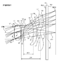
- FIG. 1 is a lens cross-sectional view illustrating a schematic configuration of an imaging lens according to Numerical Example 1 according to a first embodiment of the present invention.
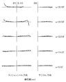
- FIG. 6 is an aberration diagram showing lateral aberration of the imaging lens according to Example 1 with the same numerical values.
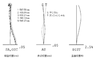
- FIG. 6 is an aberration diagram showing spherical aberration, astigmatism, and distortion of the imaging lens according to Example 1 of the same numerical value.
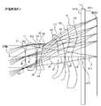
- FIG. 3 is a lens cross-sectional view illustrating a schematic configuration of an imaging lens according to Numerical Example 2 according to the first embodiment of the present invention.
- FIG. 6 is an aberration diagram showing lateral aberration of the imaging lens according to Numerical Example 2;
- FIG. 6 is an aberration diagram showing spherical aberration, astigmatism, and distortion of the imaging lens according to Example 2 of the same numerical value.
- FIG. 6 is a lens cross-sectional view illustrating a schematic configuration of an imaging lens according to Numerical Example 3 according to the first embodiment of the present invention.
- FIG. 10 is an aberration diagram showing lateral aberration of the imaging lens according to Numerical Example 3;
- FIG. 10 is an aberration diagram showing spherical aberration, astigmatism, and distortion of the imaging lens according to Numerical Example 3;
- FIG. 10 is a lens cross-sectional view illustrating a schematic configuration of an imaging lens according to Numerical Example 4 regarding the second embodiment of the present invention.
- FIG. 6 is an aberration diagram showing lateral aberration of the imaging lens according to Numerical Example 4;
- FIG. 10 is an aberration diagram showing spherical aberration, astigmatism, and distortion of the imaging lens according to Numerical Example 4;
- FIGS. 1, 4, and 7 are lens cross-sectional views corresponding to Numerical Examples 1 to 3 of the present embodiment, respectively. Since all the numerical examples have the same basic lens configuration, the lens configuration of the imaging lens according to the present embodiment will be described here with reference to the lens cross-sectional view of the numerical example 1.
- the imaging lens of the present embodiment has an aperture stop ST, a first lens L1 having a positive refractive power, and a negative refractive power in order from the object side to the image plane side.
- the second lens L2, the third lens L3 having positive refractive power, and the fourth lens L4 having positive refractive power are arranged.
- a cover glass 10 is disposed between the fourth lens L4 and the image plane.
- the cover glass 10 can be omitted.
- the aperture stop is disposed on the vertex tangent plane of the object side surface of the first lens L1.
- the position of the aperture stop is not limited to the position in the present embodiment. For example, the position of the object side relative to the apex tangent plane of the object side surface of the first lens L1 or the apex tangent plane and the first lens L1 It may be between the image side surface.
- the first lens L1 has a shape in which the curvature radius R2 of the object side surface is positive and the curvature radius R3 of the image side surface is negative, that is, a shape that becomes a biconvex lens in the vicinity of the optical axis. Is formed.
- the second lens L2 has a positive curvature radius R4 on the object side surface and a curvature radius R5 on the image side surface, and is formed in a shape that becomes a meniscus lens with a convex surface facing the object side in the vicinity of the optical axis. Yes.
- the third lens L3 has a shape in which the curvature radius R6 of the object-side surface and the curvature radius R7 of the image-side surface are both negative, and is a meniscus lens having a concave surface facing the object side in the vicinity of the optical axis. Is formed.
- the fourth lens L4 has a shape in which the curvature radius R8 of the object side surface and the curvature radius R9 of the image side surface are both positive, and has a shape that becomes a meniscus lens with a convex surface facing the object side in the vicinity of the optical axis. Is formed.
- the surface on the image plane side of the fourth lens L4 is formed in an aspherical shape that is convex toward the object side in the vicinity of the optical axis and concave toward the object side at the periphery. With such a shape of the fourth lens L4, the incident angle of the light emitted from the imaging lens to the image plane is suitably suppressed.
- the glass material of the first lens L1 and the glass material of the fourth lens L4 are the same. For this reason, compared with the case where all from the 1st lens L1 to the 4th lens L4 are formed with a separate glass material, reduction of manufacturing cost is achieved suitably.
- the imaging lens according to the present embodiment satisfies the following conditional expressions (1) to (3) and (3A). For this reason, according to the imaging lens according to the present embodiment, both miniaturization of the imaging lens and good aberration correction can be achieved.
- f focal length of the entire lens system
- L14 distance on the optical axis from the object-side surface of the first lens L1 to the image-side surface of the fourth lens L4 d23: the distance from the image-side surface of the second lens L2 Distance on the optical axis to the object side surface of the three lens
- L3 L24 Distance on the optical axis from the object side surface of the second lens L2 to the image side surface of the fourth lens L4 f12: First lens L1 Focal length between the second lens L2 and the second
- the imaging lens according to the present embodiment corrects chromatic aberration well, and the following conditional expressions (4) and (5) Satisfied. ⁇ d1> 50 (4) ⁇ d2 ⁇ 30 (5)
- the imaging lens according to the present embodiment also satisfies the following conditional expressions (6) and (7).
- ⁇ 10 (7) By satisfying these conditional expressions (6) and (7), the axial chromatic aberration and the off-axis lateral chromatic aberration are corrected more favorably.
- the lens surface of each lens is formed as an aspherical surface as necessary.
- the aspherical shape adopted for these lens surfaces is that the axis in the optical axis direction is Z, the height in the direction perpendicular to the optical axis is H, the conic coefficient is k, and the aspherical coefficients are A 4 , A 6 , A 8 , A 10 , A 12 , A 14 , and A 16 are expressed by the following formulas (the same applies to the second embodiment described later).
- f represents the focal length of the entire lens system
- Fno represents the F number
- ⁇ represents the half angle of view.
- i indicates a surface number counted from the object side
- R indicates a radius of curvature
- d indicates a distance (surface interval) between lens surfaces along the optical axis
- Nd indicates a refractive index with respect to d-line
- ⁇ d Indicates the Abbe number for the d line.
- the aspherical surface is indicated by adding a symbol of * (asterisk) after the surface number i.
- the imaging lens according to Numerical Example 1 further satisfies the following conditional expressions (8) and (9), and has a configuration in which chromatic aberration is corrected more favorably.
- ⁇ d1 ⁇ d4
- ⁇ d2 ⁇ d3 (9)
- the glass material of the second lens L2 and the glass material of the third lens L3 are the same, there are only two types of glass materials constituting the imaging lens, which reduces the manufacturing cost of the imaging lens. Further reduction is achieved.
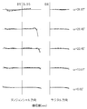
- FIG. 2 shows the lateral aberration corresponding to the half angle of view ⁇ divided into the tangential direction and the sagittal direction for the imaging lens of Numerical Example 1 (the same applies to FIGS. 5 and 8).
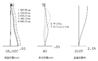
- FIG. 3 shows spherical aberration SA (mm), astigmatism AS (mm), and distortion aberration DIST (%) for the imaging lens of Numerical Example 1.
- the spherical aberration diagram shows the amount of aberration for each wavelength of 587.56 nm, 435.84 nm, 656.27 nm, 486.13 nm, and 546.07 nm as well as the sine condition violation amount OSC.
- the aberration diagrams show the aberration amount on the sagittal image surface S and the aberration amount on the tangential image surface T (the same applies to FIGS. 6 and 9). As shown in FIGS. 2 and 3, according to the imaging lens according to Numerical Example 1, various aberrations are favorably corrected.
- FIG. 5 shows lateral aberration corresponding to the half angle of view ⁇ for the imaging lens of Numerical Example 2.
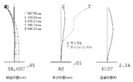
- FIG. 6 shows spherical aberration SA (mm), astigmatism AS (mm), and distortion. Each aberration DIST (%) is shown.
- the imaging lens according to Numerical Example 2 also corrects the image plane well and corrects various aberrations as well as Numerical Example 1.
- FIG. 8 shows lateral aberration corresponding to the half angle of view ⁇ for the imaging lens of Numerical Example 3
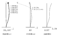
- FIG. 9 shows spherical aberration SA (mm), astigmatism AS (mm), and distortion. Each aberration DIST (%) is shown.
- the imaging lens according to Numerical Example 3 also corrects the image plane well and various aberrations as well as Numerical Example 1.
- FIG. 10 shows a cross-sectional structure of Numerical Example 4 which is a numerical example of the imaging lens according to the present embodiment.
- the imaging lens of the present embodiment has an aperture stop ST, a first lens L1 having a positive refractive power, and a negative refractive power in order from the object side to the image plane side.
- the second lens L2, the third lens L3 having a negative refractive power, and the fourth lens L4 having a positive refractive power are arranged.
- a cover glass 10 is disposed between the fourth lens L4 and the image plane.
- the aperture stop is disposed on the vertex tangent plane of the object side surface of the first lens L1 as in the imaging lens according to the first embodiment.
- the first lens L1 has a shape in which the curvature radius R2 of the object side surface is positive and the curvature radius R3 of the image side surface is negative, that is, a biconvex lens in the vicinity of the optical axis. It is formed into a shape.
- the second lens L2 has a positive curvature radius R4 on the object side surface and a curvature radius R5 on the image side surface, and is formed in a shape that becomes a meniscus lens with a convex surface facing the object side in the vicinity of the optical axis. Yes.
- the third lens L3 has a shape in which the curvature radius R6 of the object-side surface and the curvature radius R7 of the image-side surface are both negative, and is a meniscus lens having a concave surface facing the object side in the vicinity of the optical axis. Is formed.
- the fourth lens L4 has a shape in which the curvature radius R8 of the object side surface and the curvature radius R9 of the image side surface are both positive, and has a shape that becomes a meniscus lens with a convex surface facing the object side in the vicinity of the optical axis. Is formed.
- the surface on the image plane side of the fourth lens L4 is formed in an aspherical shape that is convex toward the object side in the vicinity of the optical axis and concave toward the object side at the periphery. With such a shape of the fourth lens L4, the incident angle of the light emitted from the imaging lens to the image plane is suitably suppressed.
- the glass material of the first lens L1 and the glass material of the fourth lens L4 are the same as in the imaging lens according to the first embodiment.
- the imaging lens according to the present embodiment satisfies the following conditional expressions (1) to (3) and (3A).
- f focal length of the entire lens system
- L14 distance on the optical axis from the object-side surface of the first lens L1 to the image-side surface of the fourth lens L4
- d23 the distance from the image-side surface of the second lens L2 Distance on the optical axis to the object side surface of the three lens
- L3 L24 Distance on the optical axis from the object side surface of the second lens L2 to the image side surface of the fourth lens L4
- f12 First lens L1 Focal length between the second lens L2 and the second lens L2 f34: Synthetic focal length between the third lens L3 and the fourth lens L4
- the imaging lens according to the present embodiment has the following conditional expressions (4) to (4) in the same manner as the first embodiment. 7) is satisfied.
- f represents the focal length of the entire lens system
- Fno represents the F number
- ⁇ represents the half angle of view.
- i indicates a surface number counted from the object side
- R indicates a radius of curvature
- d indicates a distance (surface interval) between lens surfaces along the optical axis
- Nd indicates a refractive index with respect to d-line
- ⁇ d Indicates the Abbe number for the d line.
- the aspherical surface is indicated by adding a symbol of * (asterisk) after the surface number i.
- the imaging lens according to Numerical Example 4 further satisfies the following conditional expressions (8) and (9), and has a configuration in which chromatic aberration is corrected more favorably.
- ⁇ d1 ⁇ d4
- ⁇ d2 ⁇ d3 (9)
- FIG. 11 shows the lateral aberration corresponding to the half angle of view ⁇ divided into the tangential direction and the sagittal direction for the imaging lens of Numerical Example 4.
- FIG. 12 shows spherical aberration SA (mm), astigmatism AS (mm), and distortion aberration DIST (%) for the imaging lens of Numerical Example 4.
- the spherical aberration diagram shows the amount of aberration for each wavelength of 587.56 nm, 435.84 nm, 656.27 nm, 486.13 nm, and 546.07 nm as well as the sine condition violation amount OSC.
- an aberration amount on the sagittal image surface S and an aberration amount on the tangential image surface T are shown.
- the imaging lens according to Numerical Example 4 also corrects various aberrations in the same manner as the imaging lens according to the first embodiment.
- the imaging lens according to the present embodiment all the lenses are formed of a plastic glass material.
- the first lens having a large refractive power from a glass-based glass material.
- the glass-based glass material has a higher total cost for molding the lens than the plastic-based glass material, there remains a problem in terms of reducing the manufacturing cost of the imaging lens.
- the imaging lens according to the present embodiment since all the lenses are formed of a plastic glass material, it is possible to suitably reduce the manufacturing cost.
- the imaging lens according to each of the above embodiments is applied to an imaging optical system such as a mobile phone, a digital still camera, a portable information terminal, a security camera, an in-vehicle camera, a network camera, and the like, Both miniaturization can be achieved.
- the present invention can be applied to an imaging lens mounted on a device that is required to have a small aberration as well as a good aberration correction capability, for example, a device such as a mobile phone or a digital still camera.
Abstract
Disclosed is an image pickup lens which can excellently correct aberration, even the lens is small in size. The image pickup lens is configured by, from the object side, sequentially disposing: a diaphragm (ST); a first lens (L1), which has a biconvex shape in the vicinity of the optical axis; a negative second lens (L2), which has a meniscus shape with the convex surface on the object side in the vicinity of the optical axis; a positive third lens (L3), which has a meniscus shape with the concave surface on the object side in the vicinity of the optical axis; and a positive fourth lens (L4). When the focal point distance of the whole lens system is expressed as f, and the distance on the optical axis from the first lens (L1) surface on the object side to the fourth lens (L4) surface on the imaging plane side is expressed as L14, the following conditional expression (1) is satisfied.
0.5<L14/f<0.8 (1)
Description
本発明は、CCDセンサやCMOSセンサ等の撮像素子上に被写体像を形成する撮像レンズに係り、携帯電話機、デジタルスティルカメラ、携帯情報端末、セキュリティカメラ、車載カメラ、ネットワークカメラ等の比較的小型のカメラに搭載されて好適な撮像レンズに関するものである。
The present invention relates to an imaging lens that forms a subject image on an imaging element such as a CCD sensor or a CMOS sensor, and is relatively small such as a mobile phone, a digital still camera, a portable information terminal, a security camera, an in-vehicle camera, and a network camera. The present invention relates to an imaging lens suitable for being mounted on a camera.
上記小型のカメラに搭載される撮像レンズには、小型化とともに、近年の高画素化された撮像素子にも対応することのできる高い光学性能が要求される。従来のように撮像素子の画素数が低かった時代には、2枚構成や3枚構成の撮像レンズによっても、撮像素子の解像度に応じた十分な光学性能の確保と小型化との両立を図ることが可能であった。しかしながら、撮像素子の高画素化に伴って要求される光学性能も高くなり、2枚や3枚のレンズ構成では、収差が良好に補正された高い光学性能の確保と小型化との両立を図ることが困難になってきた。
The imaging lens mounted on the above-mentioned small camera is required to have a high optical performance that can cope with a recent imaging device with an increased number of pixels as well as downsizing. In the era when the number of pixels of the image sensor is low as in the prior art, even with a two-lens or three-lens imaging lens, both sufficient optical performance according to the resolution of the image sensor and miniaturization are achieved. It was possible. However, the required optical performance is increased with the increase in the number of pixels of the image sensor, and in the two-lens or three-lens configuration, it is possible to achieve both high optical performance with good aberration correction and miniaturization. It has become difficult.
そこで、レンズの枚数を一枚増加させて、4枚のレンズからなるレンズ構成の採用が検討されている。例えば、特許文献1に記載の撮像レンズは、物体側から順に、物体側の面が凸形状の正の第1レンズと、物体側に凹面を向けた負のメニスカス形状の第2レンズと、物体側に凸面を向けた正のメニスカス形状の第3レンズと、物体側に凸面を向けた正のメニスカス形状の第4レンズとから構成される。当該構成において、第1~第3レンズの各レンズとレンズ系の焦点距離との各比率、第1レンズの屈折率、および第1レンズのアッベ数のそれぞれについて好ましい範囲を設定し、当該範囲内に収めることによって撮像レンズの全長の増大を抑制しつつ良好な光学性能を実現している。
Therefore, the adoption of a lens configuration consisting of four lenses by increasing the number of lenses by one is being studied. For example, an imaging lens described in Patent Document 1 includes, in order from the object side, a positive first lens having a convex surface on the object side, a second meniscus second lens having a concave surface facing the object side, and an object A positive meniscus third lens having a convex surface facing the side, and a positive meniscus fourth lens having a convex surface facing the object side. In this configuration, a preferable range is set for each ratio of the lenses of the first to third lenses and the focal length of the lens system, the refractive index of the first lens, and the Abbe number of the first lens. Therefore, good optical performance is realized while suppressing an increase in the total length of the imaging lens.
上記特許文献1に記載の撮像レンズによれば、比較的良好な収差を得ることは可能である。しかしながら、上記小型のカメラに搭載される機器そのものの小型化や高機能化は年々進展しており、撮像レンズに要求される小型化のレベルも厳しいものとなっている。上記特許文献1に記載のレンズ構成では、こうした要求に応えて撮像レンズの小型化と良好な収差補正との両立を図ることは困難である。
According to the imaging lens described in Patent Document 1, it is possible to obtain a relatively good aberration. However, miniaturization and high functionality of the devices themselves mounted on the above-mentioned small cameras are progressing year by year, and the level of miniaturization required for the imaging lens has become severe. In the lens configuration described in Patent Document 1, it is difficult to satisfy both of the demands and achieve both the downsizing of the imaging lens and good aberration correction.
本発明は上記のような従来技術の問題点に鑑みてなされたものであり、その目的は、小型でありながらも収差を良好に補正することのできる撮像レンズを提供することにある。
The present invention has been made in view of the above-described problems of the prior art, and an object of the present invention is to provide an imaging lens that can correct aberrations satisfactorily while being small in size.
上記課題を解決するために、本発明では、物体側から像面側に向かって順に、正の屈折力を有する第1レンズと、負の屈折力を有する第2レンズと、正の屈折力を有する第3レンズと、正の屈折力を有する第4レンズとを配置し、第1レンズを、物体側の面の曲率半径が正となり、像面側の面の曲率半径が負となる形状に形成し、第2レンズを、物体側の面の曲率半径および像面側の面の曲率半径が共に正となる形状に形成し、第3レンズを、物体側の面の曲率半径および像面側の面の曲率半径が共に負となる形状に形成し、レンズ系全体の焦点距離をf、第1レンズの物体側の面から第4レンズの像面側の面までの光軸上の距離をL14としたとき、下記条件式(1)を満足するように構成した。
0.5<L14/f<0.8 (1) In order to solve the above problems, in the present invention, in order from the object side to the image plane side, a first lens having a positive refractive power, a second lens having a negative refractive power, and a positive refractive power are obtained. A third lens having a positive refractive power and a first lens having a shape in which the radius of curvature of the object side surface is positive and the radius of curvature of the image side surface is negative. The second lens is formed into a shape in which both the curvature radius of the object side surface and the curvature radius of the image side surface are positive, and the third lens is formed of the curvature radius of the object side surface and the image side. And the focal length of the entire lens system is f, and the distance on the optical axis from the object-side surface of the first lens to the image-side surface of the fourth lens is When L14, the following conditional expression (1) was satisfied.
0.5 <L14 / f <0.8 (1)
また、本発明では、物体側から像面側に向かって順に、正の屈折力を有する第1レンズと、負の屈折力を有する第2レンズと、負の屈折力を有する第3レンズと、正の屈折力を有する第4レンズとを配置し、第1レンズを、物体側の面の曲率半径が正となり、像面側の面の曲率半径が負となる形状に形成し、第2レンズを、物体側の面の曲率半径および像面側の面の曲率半径が共に正となる形状に形成し、第3レンズを、物体側の面の曲率半径および像面側の面の曲率半径が共に負となる形状に形成し、レンズ系全体の焦点距離をf、第1レンズの物体側の面から第4レンズの像面側の面までの光軸上の距離をL14としたとき、下記条件式(1)を満足するように構成した。
0.5<L14/f<0.8 (1) In the present invention, in order from the object side to the image plane side, a first lens having a positive refractive power, a second lens having a negative refractive power, a third lens having a negative refractive power, A fourth lens having a positive refractive power, and the first lens is formed in a shape in which the radius of curvature of the object side surface is positive and the radius of curvature of the image side surface is negative, and the second lens Is formed in a shape in which the curvature radius of the object side surface and the curvature radius of the image side surface are both positive, and the third lens has a curvature radius of the object side surface and a curvature radius of the image side surface. When both are formed in negative shapes, the focal length of the entire lens system is f, and the distance on the optical axis from the object-side surface of the first lens to the image-side surface of the fourth lens is L14, Conditional expression (1) was satisfied.
0.5 <L14 / f <0.8 (1)
条件式(1)は、収差の補正を良好に図りつつ、撮像レンズの光軸に沿った長さ(厚さ)を短縮するための条件である。上限値「0.8」を超えると、焦点距離に対して、第1レンズの物体側の面から第4レンズの像面側の面までの光軸上の距離が長くなり、撮像レンズの小型化を図ることが困難となる。一方、下限値「0.5」を下回ると、撮像レンズの小型化には有利となるものの、撮像レンズを構成する各レンズの肉厚が極端に薄くなり、加工性・生産性が大幅に低下する。また、収差を良好に補正することが困難となる。
Conditional expression (1) is a condition for shortening the length (thickness) along the optical axis of the imaging lens while favorably correcting aberrations. When the upper limit “0.8” is exceeded, the distance on the optical axis from the object-side surface of the first lens to the image-side surface of the fourth lens becomes longer with respect to the focal length, and the imaging lens becomes smaller. It will be difficult to achieve this. On the other hand, if the value falls below the lower limit of “0.5”, it is advantageous for downsizing the imaging lens, but the thickness of each lens constituting the imaging lens becomes extremely thin, and the workability and productivity are greatly reduced. To do. In addition, it becomes difficult to correct aberrations satisfactorily.
上記構成の撮像レンズにおいては、第2レンズの像側の面から第3レンズの物体側の面までの光軸上の距離をd23、第2レンズの物体側の面から第4レンズの像面側の面までの光軸上の距離をL24としたとき、下記条件式(2)を満足することが望ましい。
0.3<d23/L24<0.7 (2) In the imaging lens configured as described above, the distance on the optical axis from the image side surface of the second lens to the object side surface of the third lens is d23, and the image surface of the fourth lens from the object side surface of the second lens When the distance on the optical axis to the side surface is L24, it is desirable to satisfy the following conditional expression (2).
0.3 <d23 / L24 <0.7 (2)
条件式(2)は、撮像レンズの厚さを短縮しつつ、撮像レンズから出射された光線の撮像素子への入射角度を一定の範囲内に抑制し、併せて像面湾曲を良好な範囲内に抑制するための条件である。周知のように、撮像素子に取り込むことのできる光線には、撮像素子の構造上、入射角度上の限界として、いわゆる最大入射角度が設けられている。この最大入射角度の範囲外の光線が撮像素子に入射した場合には、シェーディング現象によって周辺部の暗い画像となってしまう。そこで、撮像レンズから出射される光線の撮像素子への入射角度を一定の範囲内に抑制する必要がある。
Conditional expression (2) suppresses the incident angle of the light beam emitted from the imaging lens to the imaging element within a certain range while shortening the thickness of the imaging lens, and also keeps the curvature of field within a favorable range. This is a condition for suppressing the damage. As is well known, a so-called maximum incident angle is provided as a limit on the incident angle of the light beam that can be taken into the image sensor due to the structure of the image sensor. When light rays outside the range of the maximum incident angle are incident on the image sensor, a dark image in the peripheral portion is generated due to the shading phenomenon. Therefore, it is necessary to suppress the incident angle of the light beam emitted from the imaging lens to the imaging element within a certain range.
上限値「0.7」を超えると、撮像レンズから出射される光線の撮像素子への入射角度を一定の範囲内に抑制するには有利となるものの、第3レンズおよび第4レンズの有効径が増大するため、撮像レンズの小型化を図ることが困難となる。また、非点格差が増大するため、平坦な像面を得ることが困難となる。一方、下限値「0.3」を下回ると、撮像レンズの小型化には有利となるものの、撮像レンズから出射される光線の撮像素子への入射角度を一定の範囲内に抑制することが困難となる。
When the upper limit “0.7” is exceeded, it is advantageous to suppress the incident angle of the light beam emitted from the imaging lens to the imaging element within a certain range, but the effective diameters of the third lens and the fourth lens. Therefore, it is difficult to reduce the size of the imaging lens. Further, since the astigmatic difference increases, it becomes difficult to obtain a flat image surface. On the other hand, when the value is below the lower limit “0.3”, it is advantageous for downsizing of the imaging lens, but it is difficult to suppress the incident angle of the light emitted from the imaging lens to the imaging element within a certain range. It becomes.
上記構成の撮像レンズにおいては、第1レンズおよび第2レンズの合成焦点距離をf12、第3レンズおよび第4レンズの合成焦点距離をf34としたとき、下記条件式(3)を満足することが望ましい。
0.1<f12/f34<0.8 (3) In the imaging lens having the above configuration, when the combined focal length of the first lens and the second lens is f12 and the combined focal length of the third lens and the fourth lens is f34, the following conditional expression (3) may be satisfied. desirable.
0.1 <f12 / f34 <0.8 (3)
条件式(3)は、撮像レンズの厚さを短縮しつつ、軸外の倍率色収差をはじめとする各収差を良好な範囲内にバランスよく抑制するための条件である。上限値「0.8」を超えると、第3レンズおよび第4レンズの合成焦点距離に対して第1レンズおよび第2レンズの合成焦点距離が相対的に長くなり、レンズ系の主点の位置が像面側に移動するため、撮像レンズの小型化が困難となる。また、軸外の倍率色収差が補正不足(基準波長に対し短波長が-方向に増大)となり、良好な結像性能を得ることが難しくなる。一方、下限値「0.1」を下回ると、第3レンズおよび第4レンズの合成焦点距離に対して第1レンズおよび第2レンズの合成焦点距離が相対的に短くなり、第1レンズおよび第2レンズにレンズ系の屈折力が集中するため、球面収差およびコマ収差を良好な範囲内にバランスよく抑制することが困難となる。また、撮像レンズから出射された軸外光線の撮像素子への入射角度が増大し、撮像レンズから出射される光線の撮像素子への入射角度を一定の範囲内に抑制することが困難となる。
Conditional expression (3) is a condition for suppressing each aberration including off-axis lateral chromatic aberration within a good range in a well-balanced manner while reducing the thickness of the imaging lens. When the upper limit “0.8” is exceeded, the combined focal length of the first lens and the second lens becomes relatively longer than the combined focal length of the third lens and the fourth lens, and the position of the principal point of the lens system Moves to the image plane side, making it difficult to reduce the size of the imaging lens. In addition, off-axis lateral chromatic aberration is undercorrected (short wavelength increases in the negative direction with respect to the reference wavelength), making it difficult to obtain good imaging performance. On the other hand, below the lower limit “0.1”, the combined focal length of the first lens and the second lens becomes relatively shorter than the combined focal length of the third lens and the fourth lens. Since the refractive power of the lens system concentrates on the two lenses, it becomes difficult to suppress the spherical aberration and the coma aberration in a good range within a good balance. Further, the incident angle of the off-axis light beam emitted from the imaging lens to the imaging element increases, and it becomes difficult to suppress the incident angle of the light beam emitted from the imaging lens to the imaging element within a certain range.
上記構成の撮像レンズにおいては、さらに下記条件式(3A)を満足することが望ましい。
0.2<f12/f34<0.6 (3A) In the imaging lens having the above configuration, it is preferable that the following conditional expression (3A) is further satisfied.
0.2 <f12 / f34 <0.6 (3A)
0.2<f12/f34<0.6 (3A) In the imaging lens having the above configuration, it is preferable that the following conditional expression (3A) is further satisfied.
0.2 <f12 / f34 <0.6 (3A)
上記構成の撮像レンズにおいては、第1レンズのアッベ数をνd1、第2レンズのアッベ数をνd2としたとき、下記条件式(4)および(5)を満足することが望ましい。
νd1>50 (4)
νd2<30 (5) In the imaging lens having the above-described configuration, it is preferable that the following conditional expressions (4) and (5) are satisfied when the Abbe number of the first lens is νd1 and the Abbe number of the second lens is νd2.
νd1> 50 (4)
νd2 <30 (5)
νd1>50 (4)
νd2<30 (5) In the imaging lens having the above-described configuration, it is preferable that the following conditional expressions (4) and (5) are satisfied when the Abbe number of the first lens is νd1 and the Abbe number of the second lens is νd2.
νd1> 50 (4)
νd2 <30 (5)
これら条件式(4)および(5)を満足することにより、色収差を良好に補正することができる。第1レンズのアッベ数または第2レンズのアッベ数が条件式(4)あるいは条件式(5)から外れると、軸上の色収差が補正不足となり、良好な結像性能を得ることが困難となる。
Chromatic aberration can be satisfactorily corrected by satisfying these conditional expressions (4) and (5). If the Abbe number of the first lens or the Abbe number of the second lens deviates from the conditional expression (4) or the conditional expression (5), the axial chromatic aberration is insufficiently corrected, and it becomes difficult to obtain good imaging performance. .
上記構成の撮像レンズにおいては、第3レンズのアッベ数をνd3、第4レンズのアッベ数をνd4としたとき、下記条件式(6)および(7)を満足することが望ましい。
|νd1-νd4|<10 (6)
|νd2-νd3|<10 (7) In the imaging lens having the above-described configuration, it is desirable that the following conditional expressions (6) and (7) are satisfied when the Abbe number of the third lens is νd3 and the Abbe number of the fourth lens is νd4.
| Νd1-νd4 | <10 (6)
| Νd2-νd3 | <10 (7)
条件式(6)および(7)を満足することにより、軸上の色収差および軸外の倍率色収差を一層良好に補正することが可能となる。
By satisfying conditional expressions (6) and (7), it is possible to correct axial chromatic aberration and off-axis lateral chromatic aberration more satisfactorily.
また、上記構成の撮像レンズにおいて、第1レンズの硝材および第4レンズの硝材を同一とするとともに、第2レンズの硝材および第3レンズの硝材を同一とすれば、撮像レンズを構成する硝材が2種類のみとなるため、撮像レンズの製造コストを低減することができる。
In the imaging lens having the above-described configuration, if the glass material of the first lens and the glass material of the fourth lens are the same, and the glass material of the second lens and the glass material of the third lens are the same, the glass material constituting the imaging lens is obtained. Since there are only two types, the manufacturing cost of the imaging lens can be reduced.
本発明の撮像レンズによれば、撮像レンズの小型化と良好な収差補正との両立が図られ、各種の収差が良好に補正された小型の撮像レンズを提供することができる。
According to the imaging lens of the present invention, it is possible to provide a compact imaging lens in which both the downsizing of the imaging lens and good aberration correction are achieved, and various aberrations are favorably corrected.
(第1の実施の形態)
以下、本発明を具体化した第1の実施の形態について、図面を参照しながら詳細に説明する。 (First embodiment)
Hereinafter, a first embodiment of the present invention will be described in detail with reference to the drawings.
以下、本発明を具体化した第1の実施の形態について、図面を参照しながら詳細に説明する。 (First embodiment)
Hereinafter, a first embodiment of the present invention will be described in detail with reference to the drawings.
図1、図4、図7はそれぞれ、本実施の形態の数値実施例1~3に対応するレンズ断面図を示したものである。いずれの数値実施例も基本的なレンズ構成は同一であるため、ここでは数値実施例1のレンズ断面図を参照しながら、本実施の形態に係る撮像レンズのレンズ構成について説明する。
FIGS. 1, 4, and 7 are lens cross-sectional views corresponding to Numerical Examples 1 to 3 of the present embodiment, respectively. Since all the numerical examples have the same basic lens configuration, the lens configuration of the imaging lens according to the present embodiment will be described here with reference to the lens cross-sectional view of the numerical example 1.
図1に示すように、本実施の形態の撮像レンズは、物体側から像面側に向かって順に、開口絞りSTと、正の屈折力を有する第1レンズL1と、負の屈折力を有する第2レンズL2と、正の屈折力を有する第3レンズL3と、正の屈折力を有する第4レンズL4とが配列されて構成される。第4レンズL4と像面との間には、カバーガラス10が配置されている。なお、このカバーガラス10は、割愛することも可能である。また、本実施の形態では、開口絞りを、第1レンズL1の物体側面の頂点接平面上に配置している。この開口絞りの位置は、本実施の形態における位置に限定されるものではなく、例えば、第1レンズL1の物体側面の頂点接平面よりも物体側、あるいは当該頂点接平面と第1レンズL1の像面側面との間でもよい。
As shown in FIG. 1, the imaging lens of the present embodiment has an aperture stop ST, a first lens L1 having a positive refractive power, and a negative refractive power in order from the object side to the image plane side. The second lens L2, the third lens L3 having positive refractive power, and the fourth lens L4 having positive refractive power are arranged. A cover glass 10 is disposed between the fourth lens L4 and the image plane. The cover glass 10 can be omitted. In the present embodiment, the aperture stop is disposed on the vertex tangent plane of the object side surface of the first lens L1. The position of the aperture stop is not limited to the position in the present embodiment. For example, the position of the object side relative to the apex tangent plane of the object side surface of the first lens L1 or the apex tangent plane and the first lens L1 It may be between the image side surface.
上記構成の撮像レンズにおいて、第1レンズL1は、物体側の面の曲率半径R2が正となり、像面側の面の曲率半径R3が負となる形状、すなわち光軸近傍において両凸レンズとなる形状に形成されている。第2レンズL2は、物体側の面の曲率半径R4および像面側の面の曲率半径R5が共に正であり、光軸近傍において物体側に凸面を向けたメニスカスレンズとなる形状に形成されている。
In the imaging lens configured as described above, the first lens L1 has a shape in which the curvature radius R2 of the object side surface is positive and the curvature radius R3 of the image side surface is negative, that is, a shape that becomes a biconvex lens in the vicinity of the optical axis. Is formed. The second lens L2 has a positive curvature radius R4 on the object side surface and a curvature radius R5 on the image side surface, and is formed in a shape that becomes a meniscus lens with a convex surface facing the object side in the vicinity of the optical axis. Yes.
第3レンズL3は、物体側の面の曲率半径R6および像面側の面の曲率半径R7が共に負となる形状であって、光軸近傍において物体側に凹面を向けたメニスカスレンズとなる形状に形成されている。第4レンズL4は、物体側の面の曲率半径R8および像面側の面の曲率半径R9が共に正となる形状であり、光軸近傍において物体側に凸面を向けたメニスカスレンズとなる形状に形成されている。
The third lens L3 has a shape in which the curvature radius R6 of the object-side surface and the curvature radius R7 of the image-side surface are both negative, and is a meniscus lens having a concave surface facing the object side in the vicinity of the optical axis. Is formed. The fourth lens L4 has a shape in which the curvature radius R8 of the object side surface and the curvature radius R9 of the image side surface are both positive, and has a shape that becomes a meniscus lens with a convex surface facing the object side in the vicinity of the optical axis. Is formed.
また、この第4レンズL4の像面側の面は、光軸近傍において物体側に凸形状で且つ周辺部において物体側に凹形状となる非球面形状に形成されている。第4レンズL4のこのような形状により、撮像レンズから出射した光の像面への入射角が好適に抑制される。
The surface on the image plane side of the fourth lens L4 is formed in an aspherical shape that is convex toward the object side in the vicinity of the optical axis and concave toward the object side at the periphery. With such a shape of the fourth lens L4, the incident angle of the light emitted from the imaging lens to the image plane is suitably suppressed.
なお、本実施の形態に係る撮像レンズでは、第1レンズL1の硝材および第4レンズL4の硝材を同一としている。このため、第1レンズL1から第4レンズL4までの全てを別々の硝材で形成した場合に比較して製造コストの低減が好適に図られる。
In the imaging lens according to the present embodiment, the glass material of the first lens L1 and the glass material of the fourth lens L4 are the same. For this reason, compared with the case where all from the 1st lens L1 to the 4th lens L4 are formed with a separate glass material, reduction of manufacturing cost is achieved suitably.
本実施の形態に係る撮像レンズは、以下に示す条件式(1)~(3)、および(3A)を満足する。このため、本実施の形態に係る撮像レンズによれば、撮像レンズの小型化と良好な収差補正との両立が図られる。
0.5<L14/f<0.8 (1)
0.3<d23/L24<0.7 (2)
0.1<f12/f34<0.8 (3)
0.2<f12/f34<0.6 (3A)
但し、
f:レンズ系全体の焦点距離
L14:第1レンズL1の物体側の面から第4レンズL4の像面側の面までの光軸上の距離
d23:第2レンズL2の像側の面から第3レンズL3の物体側の面までの光軸上の距離
L24:第2レンズL2の物体側の面から第4レンズL4の像面側の面までの光軸上の距離
f12:第1レンズL1と第2レンズL2との合成焦点距離
f34:第3レンズL3と第4レンズL4との合成焦点距離 The imaging lens according to the present embodiment satisfies the following conditional expressions (1) to (3) and (3A). For this reason, according to the imaging lens according to the present embodiment, both miniaturization of the imaging lens and good aberration correction can be achieved.
0.5 <L14 / f <0.8 (1)
0.3 <d23 / L24 <0.7 (2)
0.1 <f12 / f34 <0.8 (3)
0.2 <f12 / f34 <0.6 (3A)
However,
f: focal length of the entire lens system L14: distance on the optical axis from the object-side surface of the first lens L1 to the image-side surface of the fourth lens L4 d23: the distance from the image-side surface of the second lens L2 Distance on the optical axis to the object side surface of the three lens L3 L24: Distance on the optical axis from the object side surface of the second lens L2 to the image side surface of the fourth lens L4 f12: First lens L1 Focal length between the second lens L2 and the second lens L2 f34: Synthetic focal length between the third lens L3 and the fourth lens L4
また、本実施の形態に係る撮像レンズは、色収差を良好に補正するために、上記条件式(1)~(3)、(3A)に加えて以下に示す条件式(4)および(5)を満足する。
νd1>50 (4)
νd2<30 (5) In addition to the above conditional expressions (1) to (3) and (3A), the imaging lens according to the present embodiment corrects chromatic aberration well, and the following conditional expressions (4) and (5) Satisfied.
νd1> 50 (4)
νd2 <30 (5)
νd1>50 (4)
νd2<30 (5) In addition to the above conditional expressions (1) to (3) and (3A), the imaging lens according to the present embodiment corrects chromatic aberration well, and the following conditional expressions (4) and (5) Satisfied.
νd1> 50 (4)
νd2 <30 (5)
さらに、本実施の形態に係る撮像レンズは下記条件式(6)および(7)も満足する。
|νd1-νd4|<10 (6)
|νd2-νd3|<10 (7)
これら条件式(6)および(7)を満足することにより、軸上の色収差および軸外の倍率色収差が一層良好に補正される。 Furthermore, the imaging lens according to the present embodiment also satisfies the following conditional expressions (6) and (7).
| Νd1-νd4 | <10 (6)
| Νd2-νd3 | <10 (7)
By satisfying these conditional expressions (6) and (7), the axial chromatic aberration and the off-axis lateral chromatic aberration are corrected more favorably.
なお、上記条件式(1)~(7)の全てを満たす必要はなく、それぞれを単独に満たすことにより、各条件式に対応する作用効果をそれぞれ得ることができる。
Note that it is not necessary to satisfy all of the above conditional expressions (1) to (7), and by satisfying each of them alone, the operational effects corresponding to each conditional expression can be obtained.
本実施の形態では、必要に応じて、各レンズのレンズ面を非球面で形成している。これらレンズ面に採用する非球面形状は、光軸方向の軸をZ、光軸に直交する方向の高さをH、円錐係数をk、非球面係数をA4、A6、A8、A10、A12、A14、A16としたとき、次式により表される(後述する第2の実施の形態においても同じ)。

In the present embodiment, the lens surface of each lens is formed as an aspherical surface as necessary. The aspherical shape adopted for these lens surfaces is that the axis in the optical axis direction is Z, the height in the direction perpendicular to the optical axis is H, the conic coefficient is k, and the aspherical coefficients are A 4 , A 6 , A 8 , A 10 , A 12 , A 14 , and A 16 are expressed by the following formulas (the same applies to the second embodiment described later).
次に、本実施の形態に係る撮像レンズの数値実施例を示す。各数値実施例において、fはレンズ系全体の焦点距離を、FnoはFナンバーを、ωは半画角をそれぞれ示す。また、iは物体側より数えた面番号を示し、Rは曲率半径を示し、dは光軸に沿ったレンズ面間の距離(面間隔)を示し、Ndはd線に対する屈折率を、νdはd線に対するアッベ数をそれぞれ示す。なお、非球面の面には、面番号iの後に*(アスタリスク)の符号を付加して示すこととする。
Next, numerical examples of the imaging lens according to the present embodiment will be shown. In each numerical example, f represents the focal length of the entire lens system, Fno represents the F number, and ω represents the half angle of view. Further, i indicates a surface number counted from the object side, R indicates a radius of curvature, d indicates a distance (surface interval) between lens surfaces along the optical axis, Nd indicates a refractive index with respect to d-line, and νd Indicates the Abbe number for the d line. The aspherical surface is indicated by adding a symbol of * (asterisk) after the surface number i.
数値実施例1
基本的なレンズデータを以下に示す。
f=4.747mm、Fno=2.800、ω=31.17°
単位 mm
面データ
面番号i R d Nd νd
(物面) ∞ ∞
1(絞り) ∞ 0.0000
2* 1.975 0.8300 1.52470 56.2(=νd1)
3* -3.200 0.0800
4* 234.000 0.2830 1.58500 29.0(=νd2)
5* 1.800 1.2700(=d23)
6* -2.640 0.4600 1.58500 29.0(=νd3)
7* -2.700 0.0100
8* 0.960 0.4500 1.52470 56.2(=νd4)
9* 0.878 0.7000
10 ∞ 0.3030 1.51633 64.12
11 ∞ 0.9760
(像面) ∞ Numerical example 1
Basic lens data is shown below.
f = 4.747mm, Fno = 2.800, ω = 31.17 °
Unit mm
Surface data Surface number i R d Nd νd
(Surface) ∞ ∞
1 (Aperture) ∞ 0.0000
2 * 1.975 0.8300 1.52470 56.2 (= νd1)
3 * -3.200 0.0800
4 * 234.000 0.2830 1.58500 29.0 (= νd2)
5 * 1.800 1.2700 (= d23)
6 * -2.640 0.4600 1.58500 29.0 (= νd3)
7 * -2.700 0.0100
8 * 0.960 0.4500 1.52470 56.2 (= νd4)
9 * 0.878 0.7000
10 ∞ 0.3030 1.51633 64.12
11 ∞ 0.9760
(Image plane) ∞
f12=6.090
f34=16.987
L14=3.383
L24=2.473 f12 = 6.090
f34 = 16.987
L14 = 3.383
L24 = 2.473
f34=16.987
L14=3.383
L24=2.473 f12 = 6.090
f34 = 16.987
L14 = 3.383
L24 = 2.473
非球面データ
第2面
k=1.535051,A4=-3.584795E-02,A6=-5.341548E-02,A8=2.682726E-02,
A10=-4.659743E-02
第3面
k=-3.102858E+01,A4=-7.981545E-02,A6=-3.753298E-02,
A8=7.692056E-02,A10=-5.998601E-02
第4面
k=-9.972116E+39,A4=-6.158896E-02,A6=-1.921885E-02,
A8=1.090468E-01,A10=-1.855461E-02,A12=-4.523068E-02,
A14=5.157794E-03
第5面
k=-7.153989,A4=4.468395E-02,A6=1.234487E-02,A8=2.658020E-02,
A10=-7.028294E-02,A12=1.641493E-01,A14=-1.126544E-01
第6面
k=-6.558193E+01,A4=6.384066E-02,A6=-5.601949E-02,
A8=-1.598106E-03,A10=-1.218430E-03,A12=9.262790E-05,
A14=2.751785E-03,A16=-1.141513E-03
第7面
k=6.705719E-01,A4=9.609024E-02,A6=-3.575929E-02,A8=-1.039675E-02,
A10=2.556040E-03,A12=1.189165E-03,A14=1.056894E-04,
A16=-1.310586E-04
第8面
k=-3.914012,A4=-8.747931E-02,A6=2.209240E-03,A8=3.555385E-03,
A10=-1.015133E-04,A12=-4.368905E-05,A14=-1.325858E-05,
A16=2.258366E-06
第9面
k=-2.979016,A4=-1.045592E-01,A6=2.583630E-02,A8=-3.520973E-03,
A10=5.731589E-06,A12=4.469465E-05,A14=-1.530316E-06,
A16=-1.856164E-07 Aspheric data 2nd surface k = 1.535051, A 4 = -3.584795E-02, A 6 = -5.341548E-02, A 8 = 2.682726E-02,
A 10 = -4.659743E-02
3rd surface k = -3.102858E + 01, A 4 = -7.981545E-02, A 6 = -3.753298E-02,
A 8 = 7.692056E-02, A 10 = -5.998601E-02
4th surface k = -9.972116E + 39, A 4 = -6.158896E-02, A 6 = -1.921885E-02,
A 8 = 1.090468E-01, A 10 = -1.855461E-02, A 12 = -4.523068E-02,
A 14 = 5.157794E-03
5th surface k = -7.153989, A 4 = 4.468395E-02, A 6 = 1.234487E-02, A 8 = 2.658020E-02,
A 10 = -7.028294E-02, A 12 = 1.641493E-01, A 14 = -1.126544E-01
6th surface k = -6.558193E + 01, A 4 = 6.384066E-02, A 6 = -5.601949E-02,
A 8 = -1.598106E-03, A 10 = -1.218430E-03, A 12 = 9.262790E-05,
A 14 = 2.751785E-03, A 16 = -1.141513E-03
7th surface k = 6.705719E-01, A 4 = 9.609024E-02, A 6 = -3.575929E-02, A 8 = -1.039675E-02,
A 10 = 2.556040E-03, A 12 = 1.189165E-03, A 14 = 1.056894E-04,
A 16 = -1.310586E-04
8th surface k = -3.914012, A 4 = -8.747931E-02, A 6 = 2.209240E-03, A 8 = 3.555385E-03,
A 10 = -1.015133E-04, A 12 = -4.368905E-05, A 14 = -1.325858E-05,
A 16 = 2.258366E-06
9th surface k = -2.979016, A 4 = -1.045592E-01, A 6 = 2.583630E-02, A 8 = -3.520973E-03,
A 10 = 5.731589E-06, A 12 = 4.469465E-05, A 14 = -1.530316E-06,
A 16 = -1.856164E-07
各条件式の値を以下に示す。
L14/f=0.713
d23/L24=0.514
f12/f34=0.359
νd1=56.2
νd2=29.0
|νd1-νd4|=0
|νd2-νd3|=0
このように、本数値実施例1に係る撮像レンズは、条件式(1)~(7)を満足する。 The value of each conditional expression is shown below.
L14 / f = 0.713
d23 / L24 = 0.514
f12 / f34 = 0.359
νd1 = 56.2
νd2 = 29.0
| Νd1-νd4 | = 0
| Νd2-νd3 | = 0
As described above, the imaging lens according to Numerical Example 1 satisfies the conditional expressions (1) to (7).
また、本数値実施例1に係る撮像レンズは、さらに下記条件式(8)および(9)を満足しており、色収差がより良好に補正される構成となっている。
νd1=νd4 (8)
νd2=νd3 (9) Further, the imaging lens according to Numerical Example 1 further satisfies the following conditional expressions (8) and (9), and has a configuration in which chromatic aberration is corrected more favorably.
νd1 = νd4 (8)
νd2 = νd3 (9)
νd1=νd4 (8)
νd2=νd3 (9) Further, the imaging lens according to Numerical Example 1 further satisfies the following conditional expressions (8) and (9), and has a configuration in which chromatic aberration is corrected more favorably.
νd1 = νd4 (8)
νd2 = νd3 (9)
また、本数値実施例1に係る撮像レンズでは、第2レンズL2の硝材および第3レンズL3の硝材を同一としているため、撮像レンズを構成する硝材が2種類のみとなり、撮像レンズの製造コストのさらなる低減が図られる。
Further, in the imaging lens according to Numerical Example 1, since the glass material of the second lens L2 and the glass material of the third lens L3 are the same, there are only two types of glass materials constituting the imaging lens, which reduces the manufacturing cost of the imaging lens. Further reduction is achieved.
図2は、数値実施例1の撮像レンズについて、半画角ωに対応する横収差をタンジェンシャル方向とサジタル方向に分けて示したものである(図5および図8において同じ)。また、図3は、数値実施例1の撮像レンズについて、球面収差SA(mm)、非点収差AS(mm)、および歪曲収差DIST(%)をそれぞれ示したものである。これら収差図において、球面収差図には、587.56nm、435.84nm、656.27nm、486.13nm、546.07nmの各波長に対する収差量とともに、正弦条件違反量OSCを併せて示し、非点収差図には、サジタル像面Sにおける収差量とタンジェンシャル像面Tにおける収差量とをそれぞれ示す(図6および図9において同じ)。図2および図3に示されるように、本数値実施例1に係る撮像レンズによれば、各種収差が良好に補正される。
FIG. 2 shows the lateral aberration corresponding to the half angle of view ω divided into the tangential direction and the sagittal direction for the imaging lens of Numerical Example 1 (the same applies to FIGS. 5 and 8). FIG. 3 shows spherical aberration SA (mm), astigmatism AS (mm), and distortion aberration DIST (%) for the imaging lens of Numerical Example 1. In these aberration diagrams, the spherical aberration diagram shows the amount of aberration for each wavelength of 587.56 nm, 435.84 nm, 656.27 nm, 486.13 nm, and 546.07 nm as well as the sine condition violation amount OSC. The aberration diagrams show the aberration amount on the sagittal image surface S and the aberration amount on the tangential image surface T (the same applies to FIGS. 6 and 9). As shown in FIGS. 2 and 3, according to the imaging lens according to Numerical Example 1, various aberrations are favorably corrected.
数値実施例2
基本的なレンズデータを以下に示す。
f=4.598mm、Fno=2.800、ω=31.99°
単位 mm
面データ
面番号i R d Nd νd
(物面) ∞ ∞
1(絞り) ∞ 0.0000
2* 1.960 0.8000 1.52470 56.2(=νd1)
3* -3.140 0.0800
4* 190.000 0.3000 1.61420 26.0(=νd2)
5* 1.830 1.2700(=d23)
6* -2.710 0.4500 1.58500 29.0(=νd3)
7* -2.580 0.0500
8* 0.937 0.4500 1.52470 56.2(=νd4)
9* 0.845 0.7000
10 ∞ 0.3000 1.51633 64.12
11 ∞ 0.8828
(像面) ∞ Numerical example 2
Basic lens data is shown below.
f = 4.598mm, Fno = 2.800, ω = 31.99 °
Unit mm
Surface data Surface number i R d Nd νd
(Surface) ∞ ∞
1 (Aperture) ∞ 0.0000
2 * 1.960 0.8000 1.52470 56.2 (= νd1)
3 * -3.140 0.0800
4 * 190.000 0.3000 1.61420 26.0 (= νd2)
5 * 1.830 1.2700 (= d23)
6 * -2.710 0.4500 1.58500 29.0 (= νd3)
7 * -2.580 0.0500
8 * 0.937 0.4500 1.52470 56.2 (= νd4)
9 * 0.845 0.7000
10 ∞ 0.3000 1.51633 64.12
11 ∞ 0.8828
(Image plane) ∞
f12=6.158
f34=13.611
L14=3.400
L24=2.520 f12 = 6.158
f34 = 13.611
L14 = 3.400
L24 = 2.520
f34=13.611
L14=3.400
L24=2.520 f12 = 6.158
f34 = 13.611
L14 = 3.400
L24 = 2.520
非球面データ
第2面
k=1.523272,A4=-3.674821E-02,A6=-5.362241E-02,A8=2.784044E-02,
A10=-4.372975E-02
第3面
k=-3.027857E+01,A4=-7.891662E-02,A6=-3.452228E-02,
A8=8.056610E-02,A10=-5.732529E-02
第4面
k=-9.972116E+39,A4=-5.972871E-02,A6=-1.854560E-02,
A8=1.097227E-01,A10=-1.673134E-02,A12=-4.210460E-02,
A14=8.864766E-03
第5面
k=-7.325117,A4=4.277749E-02,A6=1.014590E-02,A8=2.544319E-02,
A10=-6.958692E-02,A12=1.667694E-01,A14=-1.092939E-01
第6面
k=-7.444598E+01,A4=6.562546E-02,A6=-5.667216E-02,
A8=-1.987852E-03,A10=-1.433377E-03,A12=-4.663016E-05,
A14=2.676482E-03,A16=-1.172270E-03
第7面
k=7.784563E-01,A4=9.590598E-02,A6=-3.538124E-02,A8=-1.066958E-02,
A10=2.360861E-03,A12=1.114033E-03,A14=7.983932E-05,
A16=-1.405408E-04
第8面
k=-3.924204,A4=-8.876516E-02,A6=2.091896E-03,A8=3.546330E-03,
A10=-1.020165E-04,A12=-4.365898E-05,A14=-1.324021E-05,
A16=2.262549E-06
第9面
k=-2.967570,A4=-1.026086E-01,A6=2.583143E-02,A8=-3.530498E-03,
A10=4.411777E-06,A12=4.450544E-05,A14=-1.563105E-06,
A16=-1.917588E-07 Aspherical data second surface k = 1.523272, A 4 = -3.674821E-02, A 6 = -5.362241E-02, A 8 = 2.784044E-02,
A 10 = -4.372975E-02
3rd surface k = -3.027857E + 01, A 4 = -7.891662E-02, A 6 = -3.452228E-02,
A 8 = 8.056610E-02, A 10 = -5.732529E-02
4th surface k = -9.972116E + 39, A 4 = -5.972871E-02, A 6 = -1.854560E-02,
A 8 = 1.097227E-01, A 10 = -1.673134E-02, A 12 = -4.210460E-02,
A 14 = 8.864766E-03
5th surface k = -7.325117, A 4 = 4.277749E-02, A 6 = 1.014590E-02, A 8 = 2.544319E-02,
A 10 = -6.958692E-02, A 12 = 1.667694E-01, A 14 = -1.092939E-01
6th surface k = -7.444598E + 01, A 4 = 6.562546E-02, A 6 = -5.667216E-02,
A 8 = -1.987852E-03, A 10 = -1.433377E-03, A 12 = -4.663016E-05,
A 14 = 2.676482E-03, A 16 = -1.172270E-03
7th surface k = 7.784563E-01, A 4 = 9.590598E-02, A 6 = -3.538124E-02, A 8 = -1.066958E-02,
A 10 = 2.360861E-03, A 12 = 1.114033E-03, A 14 = 7.983932E-05,
A 16 = -1.405408E-04
8th surface k = -3.924204, A 4 = -8.876516E-02, A 6 = 2.091896E-03, A 8 = 3.546330E-03,
A 10 = -1.020165E-04, A 12 = -4.365898E-05, A 14 = -1.324021E-05,
A 16 = 2.262549E-06
9th surface k = -2.967570, A 4 = -1.026086E-01, A 6 = 2.583143E-02, A 8 = -3.530498E-03,
A 10 = 4.411777E-06, A 12 = 4.450544E-05, A 14 = -1.563105E-06,
A 16 = -1.917588E-07
各条件式の値を以下に示す。
L14/f=0.739
d23/L24=0.504
f12/f34=0.452
νd1=56.2
νd2=26.0
|νd1-νd4|=0
|νd2-νd3|=3
このように、本数値実施例1に係る撮像レンズは、条件式(1)~(7)を満足する。 The value of each conditional expression is shown below.
L14 / f = 0.039
d23 / L24 = 0.504
f12 / f34 = 0.552
νd1 = 56.2
νd2 = 26.0
| Νd1-νd4 | = 0
| Νd2-νd3 | = 3
As described above, the imaging lens according to Numerical Example 1 satisfies the conditional expressions (1) to (7).
図5は、数値実施例2の撮像レンズについて、半画角ωに対応する横収差を示したものであり、図6は、球面収差SA(mm)、非点収差AS(mm)、および歪曲収差DIST(%)をそれぞれ示したものである。これら図5および図6に示されるように、本数値実施例2に係る撮像レンズによっても、数値実施例1と同様に、像面が良好に補正され、各種収差が好適に補正される。
FIG. 5 shows lateral aberration corresponding to the half angle of view ω for the imaging lens of Numerical Example 2. FIG. 6 shows spherical aberration SA (mm), astigmatism AS (mm), and distortion. Each aberration DIST (%) is shown. As shown in FIG. 5 and FIG. 6, the imaging lens according to Numerical Example 2 also corrects the image plane well and corrects various aberrations as well as Numerical Example 1.
数値実施例3
基本的なレンズデータを以下に示す。
f=4.620mm、Fno=2.800、ω=31.87°
単位 mm
面データ
面番号i R d Nd νd
(物面) ∞ ∞
1(絞り) ∞ 0.0000
2* 2.000 0.8000 1.52470 56.2(=νd1)
3* -2.970 0.0500
4* 85.000 0.3200 1.61420 26.0(=νd2)
5* 1.800 1.2000(=d23)
6* -2.650 0.4100 1.58500 29.0(=νd3)
7* -2.580 0.0500
8* 0.970 0.4500 1.52470 56.2(=νd4)
9* 0.890 0.6500
10 ∞ 0.3000 1.51633 64.12
11 ∞ 1.0485
(像面) ∞ Numerical Example 3
Basic lens data is shown below.
f = 4.620mm, Fno = 2.800, ω = 31.87 °
Unit mm
Surface data Surface number i R d Nd νd
(Surface) ∞ ∞
1 (Aperture) ∞ 0.0000
2 * 2.000 0.8000 1.52470 56.2 (= νd1)
3 * -2.970 0.0500
4 * 85.000 0.3200 1.61420 26.0 (= νd2)
5 * 1.800 1.2000 (= d23)
6 * -2.650 0.4100 1.58500 29.0 (= νd3)
7 * -2.580 0.0500
8 * 0.970 0.4500 1.52470 56.2 (= νd4)
9 * 0.890 0.6500
10 ∞ 0.3000 1.51633 64.12
11 ∞ 1.0485
(Image plane) ∞
f12=6.170
f34=14.228
L14=3.280
L24=2.430 f12 = 6.170
f34 = 14.228
L14 = 3.280
L24 = 2.430
f34=14.228
L14=3.280
L24=2.430 f12 = 6.170
f34 = 14.228
L14 = 3.280
L24 = 2.430
非球面データ
第2面
k=1.569862,A4=-3.582961E-02,A6=-5.514193E-02,A8=2.111546E-02,
A10=-2.100983E-02
第3面
k=-3.448672E+01,A4=-6.360458E-02,A6=-9.427583E-03,
A8=9.524746E-02,A10=-6.873108E-02
第4面
k=2.982380E+03,A4=-1.418555E-02,A6=2.586552E-03,A8=1.130570E-01,
A10=-2.629102E-02,A12=-5.544998E-02,A14=1.816254E-02
第5面
k=-7.256649,A4=5.014734E-02,A6=2.040062E-02,A8=2.801411E-02,
A10=-7.373615E-02,A12=1.620376E-01,A14=-1.064979E-01
第6面
k=-5.649491E+01,A4=5.512272E-02,A6=-5.927976E-02,
A8=-3.831064E-03,A10=-1.920700E-03,A12=2.760719E-05,
A14=2.590711E-03,A16=-1.484510E-03
第7面
k=8.337932E-01,A4=9.156358E-02,A6=-3.623063E-02,A8=-1.090108E-02,
A10=2.123807E-03,A12=9.363177E-04,A14=4.993016E-05,
A16=-9.772932E-05
第8面
k=-3.922049,A4=-8.856960E-02,A6=2.891737E-03,A8=3.554763E-03,
A10=-1.097780E-04,A12=-4.482765E-05,A14=-1.323961E-05,
A16=2.318158E-06
第9面
k=-3.004436,A4=-1.045050E-01,A6=2.512839E-02,A8=-3.446471E-03,
A10=1.329201E-05,A12=4.482654E-05,A14=-1.526123E-06,
A16=-1.704036E-07 Aspherical data second surface k = 1.569862, A 4 = -3.582961E-02, A 6 = -5.514193E-02, A 8 = 2.111546E-02,
A 10 = -2.100983E-02
3rd surface k = -3.448672E + 01, A 4 = -6.360458E-02, A 6 = -9.427583E-03,
A 8 = 9.524746E-02, A 10 = -6.873108E-02
4th surface k = 2.982380E + 03, A 4 = -1.418555E-02, A 6 = 2.586552E-03, A 8 = 1.130570E-01,
A 10 = -2.629102E-02, A 12 = -5.544998E-02, A 14 = 1.816254E-02
5th surface k = -7.256649, A 4 = 5.014734E-02, A 6 = 2.040062E-02, A 8 = 2.801411E-02,
A 10 = -7.373615E-02, A 12 = 1.620376E-01, A 14 = -1.064979E-01
6th surface k = -5.649491E + 01, A 4 = 5.512272E-02, A 6 = -5.927976E-02,
A 8 = -3.831064E-03, A 10 = -1.920700E-03, A 12 = 2.760719E-05,
A 14 = 2.590711E-03, A 16 = -1.484510E-03
7th surface k = 8.337932E-01, A 4 = 9.156358E-02, A 6 = -3.623063E-02, A 8 = -1.090108E-02,
A 10 = 2.123807E-03, A 12 = 9.363177E-04, A 14 = 4.993016E-05,
A 16 = -9.772932E-05
8th surface k = -3.922049, A 4 = -8.856960E-02, A 6 = 2.891737E-03, A 8 = 3.554763E-03,
A 10 = -1.097780E-04, A 12 = -4.482765E-05, A 14 = -1.323961E-05,
A 16 = 2.318158E-06
9th surface k = -3.004436, A 4 = -1.045050E-01, A 6 = 2.512839E-02, A 8 = -3.446471E-03,
A 10 = 1.329201E-05, A 12 = 4.482654E-05, A 14 = -1.526123E-06,
A 16 = -1.704036E-07
各条件式の値を以下に示す。
L14/f=0.710
d23/L24=0.494
f12/f34=0.434
νd1=56.2
νd2=26.0
|νd1-νd4|=0
|νd2-νd3|=3
このように、本数値実施例3に係る撮像レンズは、条件式(1)~(7)を満足する。 The value of each conditional expression is shown below.
L14 / f = 0.710
d23 / L24 = 0.494
f12 / f34 = 0.434
νd1 = 56.2
νd2 = 26.0
| Νd1-νd4 | = 0
| Νd2-νd3 | = 3
As described above, the imaging lens according to Numerical Example 3 satisfies the conditional expressions (1) to (7).
図8は、数値実施例3の撮像レンズについて、半画角ωに対応する横収差を示したものであり、図9は、球面収差SA(mm)、非点収差AS(mm)、および歪曲収差DIST(%)をそれぞれ示したものである。これら図8および図9に示されるように、本数値実施例3に係る撮像レンズによっても、数値実施例1と同様に、像面が良好に補正され、各種収差が好適に補正される。
FIG. 8 shows lateral aberration corresponding to the half angle of view ω for the imaging lens of Numerical Example 3, and FIG. 9 shows spherical aberration SA (mm), astigmatism AS (mm), and distortion. Each aberration DIST (%) is shown. As shown in FIG. 8 and FIG. 9, the imaging lens according to Numerical Example 3 also corrects the image plane well and various aberrations as well as Numerical Example 1.
(第2の実施の形態)
次に、本発明を具体化した第2の実施の形態について、図面を参照しながら詳細に説明する。 (Second Embodiment)
Next, a second embodiment of the present invention will be described in detail with reference to the drawings.
次に、本発明を具体化した第2の実施の形態について、図面を参照しながら詳細に説明する。 (Second Embodiment)
Next, a second embodiment of the present invention will be described in detail with reference to the drawings.
図10は、本実施の形態に係る撮像レンズの一数値実施例である数値実施例4についてその断面構造を示したものである。図10に示されるように、本実施の形態の撮像レンズは、物体側から像面側に向かって順に、開口絞りSTと、正の屈折力を有する第1レンズL1と、負の屈折力を有する第2レンズL2と、負の屈折力を有する第3レンズL3と、正の屈折力を有する第4レンズL4とが配列されて構成される。第4レンズL4と像面との間には、カバーガラス10が配置されている。また、本実施の形態においても、上記第1の実施の形態に係る撮像レンズと同様、開口絞りを、第1レンズL1の物体側面の頂点接平面上に配置している。
FIG. 10 shows a cross-sectional structure of Numerical Example 4 which is a numerical example of the imaging lens according to the present embodiment. As shown in FIG. 10, the imaging lens of the present embodiment has an aperture stop ST, a first lens L1 having a positive refractive power, and a negative refractive power in order from the object side to the image plane side. The second lens L2, the third lens L3 having a negative refractive power, and the fourth lens L4 having a positive refractive power are arranged. A cover glass 10 is disposed between the fourth lens L4 and the image plane. Also in the present embodiment, the aperture stop is disposed on the vertex tangent plane of the object side surface of the first lens L1 as in the imaging lens according to the first embodiment.
上記構成の撮像レンズにおいて、第1レンズL1の形状は、物体側の面の曲率半径R2が正となり、像面側の面の曲率半径R3が負となる形状、すなわち光軸近傍において両凸レンズとなる形状に形成されている。第2レンズL2は、物体側の面の曲率半径R4および像面側の面の曲率半径R5が共に正であり、光軸近傍において物体側に凸面を向けたメニスカスレンズとなる形状に形成されている。
In the imaging lens having the above configuration, the first lens L1 has a shape in which the curvature radius R2 of the object side surface is positive and the curvature radius R3 of the image side surface is negative, that is, a biconvex lens in the vicinity of the optical axis. It is formed into a shape. The second lens L2 has a positive curvature radius R4 on the object side surface and a curvature radius R5 on the image side surface, and is formed in a shape that becomes a meniscus lens with a convex surface facing the object side in the vicinity of the optical axis. Yes.
第3レンズL3は、物体側の面の曲率半径R6および像面側の面の曲率半径R7が共に負となる形状であって、光軸近傍において物体側に凹面を向けたメニスカスレンズとなる形状に形成されている。第4レンズL4は、物体側の面の曲率半径R8および像面側の面の曲率半径R9が共に正となる形状であり、光軸近傍において物体側に凸面を向けたメニスカスレンズとなる形状に形成されている。
The third lens L3 has a shape in which the curvature radius R6 of the object-side surface and the curvature radius R7 of the image-side surface are both negative, and is a meniscus lens having a concave surface facing the object side in the vicinity of the optical axis. Is formed. The fourth lens L4 has a shape in which the curvature radius R8 of the object side surface and the curvature radius R9 of the image side surface are both positive, and has a shape that becomes a meniscus lens with a convex surface facing the object side in the vicinity of the optical axis. Is formed.
また、この第4レンズL4の像面側の面は、光軸近傍において物体側に凸形状で且つ周辺部において物体側に凹形状となる非球面形状に形成されている。第4レンズL4のこのような形状により、撮像レンズから出射した光の像面への入射角が好適に抑制される。
The surface on the image plane side of the fourth lens L4 is formed in an aspherical shape that is convex toward the object side in the vicinity of the optical axis and concave toward the object side at the periphery. With such a shape of the fourth lens L4, the incident angle of the light emitted from the imaging lens to the image plane is suitably suppressed.
なお、本実施の形態に係る撮像レンズでは、上記第1の実施の形態に係る撮像レンズと同様、第1レンズL1の硝材および第4レンズL4の硝材を同一としている。
In the imaging lens according to the present embodiment, the glass material of the first lens L1 and the glass material of the fourth lens L4 are the same as in the imaging lens according to the first embodiment.
本実施の形態に係る撮像レンズは、以下に示す条件式(1)~(3)、および(3A)を満足する。
0.5<L14/f<0.8 (1)
0.3<d23/L24<0.7 (2)
0.1<f12/f34<0.8 (3)
0.2<f12/f34<0.6 (3A)
但し、
f:レンズ系全体の焦点距離
L14:第1レンズL1の物体側の面から第4レンズL4の像面側の面までの光軸上の距離
d23:第2レンズL2の像側の面から第3レンズL3の物体側の面までの光軸上の距離
L24:第2レンズL2の物体側の面から第4レンズL4の像面側の面までの光軸上の距離
f12:第1レンズL1と第2レンズL2との合成焦点距離
f34:第3レンズL3と第4レンズL4との合成焦点距離 The imaging lens according to the present embodiment satisfies the following conditional expressions (1) to (3) and (3A).
0.5 <L14 / f <0.8 (1)
0.3 <d23 / L24 <0.7 (2)
0.1 <f12 / f34 <0.8 (3)
0.2 <f12 / f34 <0.6 (3A)
However,
f: focal length of the entire lens system L14: distance on the optical axis from the object-side surface of the first lens L1 to the image-side surface of the fourth lens L4 d23: the distance from the image-side surface of the second lens L2 Distance on the optical axis to the object side surface of the three lens L3 L24: Distance on the optical axis from the object side surface of the second lens L2 to the image side surface of the fourth lens L4 f12: First lens L1 Focal length between the second lens L2 and the second lens L2 f34: Synthetic focal length between the third lens L3 and the fourth lens L4
また、本実施の形態に係る撮像レンズは、上記第1の実施の形態と同様、上記条件式(1)~(3)、および(3A)に加えて以下に示す条件式(4)~(7)を満足する。
νd1>50 (4)
νd2<30 (5)
|νd1-νd4|<10 (6)
|νd2-νd3|<10 (7) In addition to the conditional expressions (1) to (3) and (3A), the imaging lens according to the present embodiment has the following conditional expressions (4) to (4) in the same manner as the first embodiment. 7) is satisfied.
νd1> 50 (4)
νd2 <30 (5)
| Νd1-νd4 | <10 (6)
| Νd2-νd3 | <10 (7)
なお、上記条件式(1)~(7)の全てを満たす必要はなく、それぞれを単独に満たすことにより、各条件式に対応する作用効果をそれぞれ得ることができる。
Note that it is not necessary to satisfy all of the above conditional expressions (1) to (7), and by satisfying each of them alone, the operational effects corresponding to each conditional expression can be obtained.
次に、本実施の形態に係る撮像レンズの数値実施例を示す。各数値実施例において、fはレンズ系全体の焦点距離を、FnoはFナンバーを、ωは半画角をそれぞれ示す。また、iは物体側より数えた面番号を示し、Rは曲率半径を示し、dは光軸に沿ったレンズ面間の距離(面間隔)を示し、Ndはd線に対する屈折率を、νdはd線に対するアッベ数をそれぞれ示す。なお、非球面の面には、面番号iの後に*(アスタリスク)の符号を付加して示すこととする。
Next, numerical examples of the imaging lens according to the present embodiment will be shown. In each numerical example, f represents the focal length of the entire lens system, Fno represents the F number, and ω represents the half angle of view. Further, i indicates a surface number counted from the object side, R indicates a radius of curvature, d indicates a distance (surface interval) between lens surfaces along the optical axis, Nd indicates a refractive index with respect to d-line, and νd Indicates the Abbe number for the d line. The aspherical surface is indicated by adding a symbol of * (asterisk) after the surface number i.
数値実施例4
基本的なレンズデータを以下に示す。
f=4.533mm、Fno=2.800、ω=32.36°
単位 mm
面データ
面番号i R d Nd νd
(物面) ∞ ∞
1(絞り) ∞ 0.0000
2* 1.750 0.6400 1.52470 56.2(=νd1)
3* -7.580 0.0500
4* 2.980 0.2750 1.61420 26.0(=νd2)
5* 1.340 1.1400(=d23)
6* -1.080 0.3300 1.61420 26.0(=νd3)
7* -1.460 0.0300
8* 1.340 0.7400 1.52470 56.2(=νd4)
9* 1.790 0.7000
10 ∞ 0.3000 1.51633 64.12
11 ∞ 0.9590
(像面) ∞ Numerical Example 4
Basic lens data is shown below.
f = 4.533mm, Fno = 2.800, ω = 32.36 °
Unit mm
Surface data Surface number i R d Nd νd
(Surface) ∞ ∞
1 (Aperture) ∞ 0.0000
2 * 1.750 0.6400 1.52470 56.2 (= νd1)
3 * -7.580 0.0500
4 * 2.980 0.2750 1.61420 26.0 (= νd2)
5 * 1.340 1.1400 (= d23)
6 * -1.080 0.3300 1.61420 26.0 (= νd3)
7 * -1.460 0.0300
8 * 1.340 0.7400 1.52470 56.2 (= νd4)
9 * 1.790 0.7000
10 ∞ 0.3000 1.51633 64.12
11 ∞ 0.9590
(Image plane) ∞
f12=5.368
f34=16.859
L14=3.205
L24=2.515 f12 = 5.368
f34 = 16.859
L14 = 3.205
L24 = 2.515
f34=16.859
L14=3.205
L24=2.515 f12 = 5.368
f34 = 16.859
L14 = 3.205
L24 = 2.515
非球面データ
第2面
k=6.786206E-01,A4=-2.452177E-02,A6=-4.531117E-02,A8=1.799352E-02,
A10=-4.777095E-02
第3面
k=-5.729004E+02,A4=-9.783542E-02,A6=3.888487E-04,A8=4.415689E-02,
A10=-5.564102E-02
第4面
k=0.000000,A4=-7.770589E-02,A6=-1.491525E-01,A8=2.686134E-01,
A10=1.252068E-01,A12=-5.138390E-01,A14=3.257669E-01
第5面
k=-3.783573,A4=6.655314E-02,A6=-2.019505E-03,A8=-5.264757E-02,
A10=-9.946107E-02,A12=9.168460E-01,A14=-9.366545E-01
第6面
k=-7.739841,A4=-2.600109E-02,A6=-2.781476E-02,A8=1.721137E-02,
A10=-6.618718E-03,A12=-1.020692E-03,A14=3.566882E-03,
A16=-3.501108E-03
第7面
k=-3.257123E-01,A4=6.651450E-02,A6=5.551070E-03,A8=2.372390E-04,
A10=1.073662E-03,A12=-1.401114E-03,A14=-6.211786E-04,
A16=3.980215E-04
第8面
k=-1.115632E+01,A4=-1.152918E-01,A6=3.977347E-02,
A8=-1.926234E-03,A10=-2.682682E-03,A12=4.506907E-05,
A14=1.366224E-04,A16=-7.319281E-06
第9面
k=-7.835931,A4=-9.770814E-02,A6=2.656391E-02,A8=-3.951961E-03,
A10=-3.034931E-04,A12=3.770115E-05,A14=3.157577E-05,
A16=-6.376041E-06 Aspherical data second surface k = 6.786206E-01, A 4 = -2.452177E-02, A 6 = -4.531117E-02, A 8 = 1.799352E-02,
A 10 = -4.777095E-02
3rd surface k = -5.729004E + 02, A 4 = -9.783542E-02, A 6 = 3.888487E-04, A 8 = 4.415689E-02,
A 10 = -5.564102E-02
4th surface k = 0.000000, A 4 = -7.770589E-02, A 6 = -1.491525E-01, A 8 = 2.686134E-01,
A 10 = 1.252068E-01, A 12 = -5.138390E-01, A 14 = 3.257669E-01
5th surface k = -3.783573, A 4 = 6.655314E-02, A 6 = -2.019505E-03, A 8 = -5.264757E-02,
A 10 = -9.946107E-02, A 12 = 9.168460E-01, A 14 = -9.366545E-01
6th surface k = -7.739841, A 4 = -2.600109E-02, A 6 = -2.781476E-02, A 8 = 1.721137E-02,
A 10 = -6.618718E-03, A 12 = -1.020692E-03, A 14 = 3.566882E-03,
A 16 = -3.501108E-03
7th surface k = -3.257123E-01, A 4 = 6.651450E-02, A 6 = 5.551070E-03, A 8 = 2.372390E-04,
A 10 = 1.073662E-03, A 12 = -1.401114E-03, A 14 = -6.211786E-04,
A 16 = 3.980215E-04
8th surface k = -1.115632E + 01, A 4 = -1.152918E-01, A 6 = 3.977347E-02,
A 8 = -1.926234E-03, A 10 = -2.682682E-03, A 12 = 4.506907E-05,
A 14 = 1.366224E-04, A 16 = -7.319281E-06
9th surface k = -7.835931, A 4 = -9.770814E-02, A 6 = 2.656391E-02, A 8 = -3.951961E-03,
A 10 = -3.034931E-04, A 12 = 3.770115E-05, A 14 = 3.157577E-05,
A 16 = -6.376041E-06
各条件式の値を以下に示す。
L14/f=0.707
d23/L24=0.453
f12/f34=0.318
νd1=56.2
νd2=26.0
|νd1-νd4|=0
|νd2-νd3|=0
このように、本数値実施例4に係る撮像レンズは、条件式(1)~(7)を満足する。 The value of each conditional expression is shown below.
L14 / f = 0.707
d23 / L24 = 0.453
f12 / f34 = 0.318
νd1 = 56.2
νd2 = 26.0
| Νd1-νd4 | = 0
| Νd2-νd3 | = 0
As described above, the imaging lens according to Numerical Example 4 satisfies the conditional expressions (1) to (7).
また、本数値実施例4に係る撮像レンズは、さらに下記条件式(8)および(9)を満足しており、色収差がより良好に補正される構成となっている。
νd1=νd4 (8)
νd2=νd3 (9) The imaging lens according to Numerical Example 4 further satisfies the following conditional expressions (8) and (9), and has a configuration in which chromatic aberration is corrected more favorably.
νd1 = νd4 (8)
νd2 = νd3 (9)
νd1=νd4 (8)
νd2=νd3 (9) The imaging lens according to Numerical Example 4 further satisfies the following conditional expressions (8) and (9), and has a configuration in which chromatic aberration is corrected more favorably.
νd1 = νd4 (8)
νd2 = νd3 (9)
また、本数値実施例4に係る撮像レンズでは、第2レンズL2の硝材および第3レンズL3の硝材を同一としているため、撮像レンズを構成する硝材が2種類のみとなり、撮像レンズの製造コストのさらなる低減が図られる。
In the imaging lens according to Numerical Example 4, since the glass material of the second lens L2 and the glass material of the third lens L3 are the same, there are only two types of glass materials constituting the imaging lens, which reduces the manufacturing cost of the imaging lens. Further reduction is achieved.
図11は、数値実施例4の撮像レンズについて、半画角ωに対応する横収差をタンジェンシャル方向とサジタル方向に分けて示したものである。また、図12は、数値実施例4の撮像レンズについて、球面収差SA(mm)、非点収差AS(mm)、および歪曲収差DIST(%)をそれぞれ示したものである。これら収差図において、球面収差図には、587.56nm、435.84nm、656.27nm、486.13nm、546.07nmの各波長に対する収差量とともに、正弦条件違反量OSCを併せて示し、非点収差図には、サジタル像面Sにおける収差量とタンジェンシャル像面Tにおける収差量とをそれぞれ示す。図11および図12に示されるように、本数値実施例4に係る撮像レンズによっても、上記第1の実施の形態に係る撮像レンズと同様、各種収差が良好に補正される。
FIG. 11 shows the lateral aberration corresponding to the half angle of view ω divided into the tangential direction and the sagittal direction for the imaging lens of Numerical Example 4. FIG. 12 shows spherical aberration SA (mm), astigmatism AS (mm), and distortion aberration DIST (%) for the imaging lens of Numerical Example 4. In these aberration diagrams, the spherical aberration diagram shows the amount of aberration for each wavelength of 587.56 nm, 435.84 nm, 656.27 nm, 486.13 nm, and 546.07 nm as well as the sine condition violation amount OSC. In the aberration diagram, an aberration amount on the sagittal image surface S and an aberration amount on the tangential image surface T are shown. As shown in FIGS. 11 and 12, the imaging lens according to Numerical Example 4 also corrects various aberrations in the same manner as the imaging lens according to the first embodiment.
ところで、本実施の形態に係る撮像レンズでは、全てのレンズがプラスチック系の硝材で形成されている。従来、屈折力の大きい第1レンズをガラス系の硝材で形成することが一般的であった。しかし、ガラス系の硝材はプラスチック系の硝材に比較してレンズに成形するまでのトータルコストが高くなるため、撮像レンズの製造コスト低減の面からも課題が残っていた。本実施の形態に係る撮像レンズでは、全てのレンズがプラスティック系の硝材で形成されているため、製造コストの低減を好適に図ることが可能である。
By the way, in the imaging lens according to the present embodiment, all the lenses are formed of a plastic glass material. Conventionally, it has been common to form the first lens having a large refractive power from a glass-based glass material. However, since the glass-based glass material has a higher total cost for molding the lens than the plastic-based glass material, there remains a problem in terms of reducing the manufacturing cost of the imaging lens. In the imaging lens according to the present embodiment, since all the lenses are formed of a plastic glass material, it is possible to suitably reduce the manufacturing cost.
したがって、上記各実施の形態に係る撮像レンズを、携帯電話機、デジタルスティルカメラ、携帯情報端末、セキュリティカメラ、車載カメラ、ネットワークカメラ等の撮像光学系に適用した場合、当該カメラ等の高機能化と小型化の両立を図ることができる。
Therefore, when the imaging lens according to each of the above embodiments is applied to an imaging optical system such as a mobile phone, a digital still camera, a portable information terminal, a security camera, an in-vehicle camera, a network camera, and the like, Both miniaturization can be achieved.
本発明は、撮像レンズとして小型化とともに良好な収差補正能力が要求される機器、例えば携帯電話機やデジタルスティルカメラ等の機器に搭載される撮像レンズに適用することができる。
The present invention can be applied to an imaging lens mounted on a device that is required to have a small aberration as well as a good aberration correction capability, for example, a device such as a mobile phone or a digital still camera.
ST 絞り
L1 第1レンズ
L2 第2レンズ
L3 第3レンズ
L4 第4レンズ
10 カバーガラス ST Aperture L1 1st lens L2 2nd lens L3 3rd lensL4 4th lens 10 Cover glass
L1 第1レンズ
L2 第2レンズ
L3 第3レンズ
L4 第4レンズ
10 カバーガラス ST Aperture L1 1st lens L2 2nd lens L3 3rd lens
Claims (7)
- 物体側から像面側に向かって順に、正の屈折力を有する第1レンズと、負の屈折力を有する第2レンズと、正の屈折力を有する第3レンズと、正の屈折力を有する第4レンズとを配置して構成され、
前記第1レンズは、物体側の面の曲率半径が正となり、像面側の面の曲率半径が負となる形状に形成されており
前記第2レンズは、物体側の面の曲率半径および像面側の面の曲率半径が共に正となる形状に形成されており、
前記第3レンズは、物体側の面の曲率半径および像面側の面の曲率半径が共に負となる形状に形成されており、
レンズ系全体の焦点距離をf、前記第1レンズの物体側の面から前記第4レンズの像面側の面までの光軸上の距離をL14としたとき、
0.5<L14/f<0.8
を満足することを特徴とする撮像レンズ。 A first lens having a positive refractive power, a second lens having a negative refractive power, a third lens having a positive refractive power, and a positive refractive power in order from the object side to the image plane side. Arranged with a fourth lens,
The first lens has a shape in which the curvature radius of the object side surface is positive and the curvature radius of the image side surface is negative. The second lens has a curvature radius and an image of the object side surface. It is formed in a shape that the curvature radius of the surface side surface is both positive,
The third lens is formed in a shape in which both the radius of curvature of the object side surface and the radius of curvature of the image side surface are negative,
When the focal length of the entire lens system is f and the distance on the optical axis from the object-side surface of the first lens to the image-side surface of the fourth lens is L14,
0.5 <L14 / f <0.8
An imaging lens characterized by satisfying - 物体側から像面側に向かって順に、正の屈折力を有する第1レンズと、負の屈折力を有する第2レンズと、負の屈折力を有する第3レンズと、正の屈折力を有する第4レンズとを配置して構成され、
前記第1レンズは、物体側の面の曲率半径が正となり、像面側の面の曲率半径が負となる形状に形成されており
前記第2レンズは、物体側の面の曲率半径および像面側の面の曲率半径が共に正となる形状に形成されており、
前記第3レンズは、物体側の面の曲率半径および像面側の面の曲率半径が共に負となる形状に形成されており、
レンズ系全体の焦点距離をf、前記第1レンズの物体側の面から前記第4レンズの像面側の面までの光軸上の距離をL14としたとき、
0.5<L14/f<0.8
を満足することを特徴とする撮像レンズ。 A first lens having a positive refractive power, a second lens having a negative refractive power, a third lens having a negative refractive power, and a positive refractive power in order from the object side to the image plane side. Arranged with a fourth lens,
The first lens has a shape in which the curvature radius of the object side surface is positive and the curvature radius of the image side surface is negative. The second lens has a curvature radius and an image of the object side surface. It is formed in a shape that the curvature radius of the surface side surface is both positive,
The third lens is formed in a shape in which both the radius of curvature of the object side surface and the radius of curvature of the image side surface are negative,
When the focal length of the entire lens system is f and the distance on the optical axis from the object-side surface of the first lens to the image-side surface of the fourth lens is L14,
0.5 <L14 / f <0.8
An imaging lens characterized by satisfying - 前記第2レンズの像側の面から前記第3レンズの物体側の面までの光軸上の距離をd23、前記第2レンズの物体側の面から前記第4レンズの像面側の面までの光軸上の距離をL24としたとき、
0.3<d23/L24<0.7
を満足することを特徴とする請求項1または2に記載の撮像レンズ。 The distance on the optical axis from the image-side surface of the second lens to the object-side surface of the third lens is d23, and from the object-side surface of the second lens to the image-side surface of the fourth lens When the distance on the optical axis is L24,
0.3 <d23 / L24 <0.7
The imaging lens according to claim 1, wherein: - 前記第1レンズおよび前記第2レンズの合成焦点距離をf12、前記第3レンズおよび前記第4レンズの合成焦点距離をf34としたとき、
0.1<f12/f34<0.8
を満足することを特徴とする請求項1~3のいずれか一項に記載の撮像レンズ。 When the combined focal length of the first lens and the second lens is f12, and the combined focal length of the third lens and the fourth lens is f34,
0.1 <f12 / f34 <0.8
The imaging lens according to any one of claims 1 to 3, wherein: - 前記第1レンズのアッベ数をνd1、前記第2レンズのアッベ数をνd2としたとき
νd1>50 かつ νd2<30
を満足することを特徴とする請求項1~4のいずれか一項に記載の撮像レンズ。 When the Abbe number of the first lens is νd1, and the Abbe number of the second lens is νd2, νd1> 50 and νd2 <30.
The imaging lens according to any one of claims 1 to 4, wherein: - 前記第3レンズのアッベ数をνd3、前記第4レンズのアッベ数をνd4としたとき、
|νd1-νd4|<10 かつ |νd2-νd3|<10
を満足することを特徴とする請求項1~5のいずれか一項に記載の撮像レンズ。 When the Abbe number of the third lens is νd3 and the Abbe number of the fourth lens is νd4,
| Νd1-νd4 | <10 and | νd2-νd3 | <10
The imaging lens according to any one of claims 1 to 5, wherein: - 前記第1レンズの硝材および前記第4レンズの硝材が同一であり、前記第2レンズの硝材および前記第3レンズの硝材が同一である、
ことを特徴とする請求項1~6のいずれか一項に記載の撮像レンズ。 The glass material of the first lens and the glass material of the fourth lens are the same, and the glass material of the second lens and the glass material of the third lens are the same.
The imaging lens according to any one of claims 1 to 6, wherein:
Priority Applications (2)
| Application Number | Priority Date | Filing Date | Title |
|---|---|---|---|
| CN201080045595.2A CN102576144B (en) | 2009-10-22 | 2010-10-20 | Image pickup lens |
| US13/445,154 US8477434B2 (en) | 2009-10-22 | 2012-04-12 | Imaging lens |
Applications Claiming Priority (2)
| Application Number | Priority Date | Filing Date | Title |
|---|---|---|---|
| JP2009-243049 | 2009-10-22 | ||
| JP2009243049A JP5526303B2 (en) | 2009-10-22 | 2009-10-22 | Imaging lens |
Related Child Applications (1)
| Application Number | Title | Priority Date | Filing Date |
|---|---|---|---|
| US13/445,154 Continuation US8477434B2 (en) | 2009-10-22 | 2012-04-12 | Imaging lens |
Publications (1)
| Publication Number | Publication Date |
|---|---|
| WO2011049107A1 true WO2011049107A1 (en) | 2011-04-28 |
Family
ID=43900330
Family Applications (1)
| Application Number | Title | Priority Date | Filing Date |
|---|---|---|---|
| PCT/JP2010/068442 WO2011049107A1 (en) | 2009-10-22 | 2010-10-20 | Image pickup lens |
Country Status (4)
| Country | Link |
|---|---|
| US (1) | US8477434B2 (en) |
| JP (1) | JP5526303B2 (en) |
| CN (1) | CN102576144B (en) |
| WO (1) | WO2011049107A1 (en) |
Cited By (1)
| Publication number | Priority date | Publication date | Assignee | Title |
|---|---|---|---|---|
| TWI709782B (en) * | 2020-03-25 | 2020-11-11 | 新鉅科技股份有限公司 | Four-piece infrared single wavelength lens system |
Families Citing this family (7)
| Publication number | Priority date | Publication date | Assignee | Title |
|---|---|---|---|---|
| JP5467342B2 (en) * | 2009-11-25 | 2014-04-09 | 株式会社オプトロジック | Imaging lens |
| CN103135206B (en) | 2012-09-07 | 2016-04-20 | 玉晶光电(厦门)有限公司 | Portable electron device and its optical imaging lens |
| JP2015102849A (en) * | 2013-11-28 | 2015-06-04 | カンタツ株式会社 | Image capturing lens |
| TWI620968B (en) | 2016-12-15 | 2018-04-11 | 大立光電股份有限公司 | Optical photographing lens system, image capturing apparatus and electronic device |
| JP6434066B2 (en) * | 2017-01-23 | 2018-12-05 | カンタツ株式会社 | Imaging lens |
| CN113189746B (en) | 2017-12-08 | 2022-09-02 | 大立光电股份有限公司 | Electronic device |
| CN112799217B (en) * | 2021-02-05 | 2023-02-10 | 玉晶光电(厦门)有限公司 | Optical imaging lens |
Citations (4)
| Publication number | Priority date | Publication date | Assignee | Title |
|---|---|---|---|---|
| US20080186594A1 (en) * | 2007-02-06 | 2008-08-07 | Samsung Electro-Mechanics Co., Ltd. | Subminiature imaging optical system |
| US20080291553A1 (en) * | 2007-02-12 | 2008-11-27 | Samsung Electro-Mechanics Co., Ltd. | Subminiature imaging optical system |
| JP2009098513A (en) * | 2007-10-18 | 2009-05-07 | Fujinon Corp | Four-lens-type small imaging lens, camera module, and imaging apparatus |
| JP2009288377A (en) * | 2008-05-28 | 2009-12-10 | Hitachi Maxell Ltd | Lens unit and camera module |
Family Cites Families (6)
| Publication number | Priority date | Publication date | Assignee | Title |
|---|---|---|---|---|
| JP2005004028A (en) * | 2003-06-13 | 2005-01-06 | Olympus Corp | Imaging optical system and imaging apparatus using it |
| JP2005024889A (en) * | 2003-07-02 | 2005-01-27 | Olympus Corp | Image-formation optical system and imaging apparatus using the same |
| JP4828317B2 (en) | 2005-09-29 | 2011-11-30 | 富士フイルム株式会社 | Imaging lens |
| JP2008090150A (en) * | 2006-10-04 | 2008-04-17 | Sony Corp | Imaging lens and imaging apparatus |
| JP2009098515A (en) * | 2007-10-18 | 2009-05-07 | Fujinon Corp | Four-lens-type small imaging lens, camera module, and imaging apparatus |
| JP5467342B2 (en) * | 2009-11-25 | 2014-04-09 | 株式会社オプトロジック | Imaging lens |
-
2009
- 2009-10-22 JP JP2009243049A patent/JP5526303B2/en active Active
-
2010
- 2010-10-20 CN CN201080045595.2A patent/CN102576144B/en active Active
- 2010-10-20 WO PCT/JP2010/068442 patent/WO2011049107A1/en active Application Filing
-
2012
- 2012-04-12 US US13/445,154 patent/US8477434B2/en active Active
Patent Citations (4)
| Publication number | Priority date | Publication date | Assignee | Title |
|---|---|---|---|---|
| US20080186594A1 (en) * | 2007-02-06 | 2008-08-07 | Samsung Electro-Mechanics Co., Ltd. | Subminiature imaging optical system |
| US20080291553A1 (en) * | 2007-02-12 | 2008-11-27 | Samsung Electro-Mechanics Co., Ltd. | Subminiature imaging optical system |
| JP2009098513A (en) * | 2007-10-18 | 2009-05-07 | Fujinon Corp | Four-lens-type small imaging lens, camera module, and imaging apparatus |
| JP2009288377A (en) * | 2008-05-28 | 2009-12-10 | Hitachi Maxell Ltd | Lens unit and camera module |
Cited By (1)
| Publication number | Priority date | Publication date | Assignee | Title |
|---|---|---|---|---|
| TWI709782B (en) * | 2020-03-25 | 2020-11-11 | 新鉅科技股份有限公司 | Four-piece infrared single wavelength lens system |
Also Published As
| Publication number | Publication date |
|---|---|
| US20120200945A1 (en) | 2012-08-09 |
| JP2011090127A (en) | 2011-05-06 |
| US8477434B2 (en) | 2013-07-02 |
| JP5526303B2 (en) | 2014-06-18 |
| CN102576144A (en) | 2012-07-11 |
| CN102576144B (en) | 2014-09-03 |
Similar Documents
| Publication | Publication Date | Title |
|---|---|---|
| JP5201690B2 (en) | Imaging lens | |
| JP5371148B2 (en) | Imaging lens | |
| JP5750698B2 (en) | Imaging lens | |
| JP5201679B2 (en) | Imaging lens | |
| JP5754670B2 (en) | Imaging lens | |
| JP5467342B2 (en) | Imaging lens | |
| JP5577531B2 (en) | Imaging lens | |
| JP5280326B2 (en) | Imaging lens | |
| JP5526303B2 (en) | Imaging lens | |
| JP5613962B2 (en) | Imaging lens | |
| JP5568732B2 (en) | Imaging lens | |
| JP5366314B2 (en) | Imaging lens | |
| JP5839357B2 (en) | Imaging lens | |
| JP5548845B2 (en) | Imaging lens | |
| JP2010276836A (en) | Imaging lens | |
| JP5308915B2 (en) | Imaging lens | |
| WO2011111561A1 (en) | Imaging lens | |
| WO2009133657A1 (en) | Imaging lens | |
| WO2012005070A1 (en) | Image-capturing lens | |
| JP5187951B2 (en) | Imaging lens |
Legal Events
| Date | Code | Title | Description |
|---|---|---|---|
| WWE | Wipo information: entry into national phase |
Ref document number: 201080045595.2 Country of ref document: CN |
|
| 121 | Ep: the epo has been informed by wipo that ep was designated in this application |
Ref document number: 10824956 Country of ref document: EP Kind code of ref document: A1 |
|
| 122 | Ep: pct application non-entry in european phase |
Ref document number: 10824956 Country of ref document: EP Kind code of ref document: A1 |