WO2011043328A1 - Wireless base station device, mobile terminal device and wireless communication method - Google Patents
Wireless base station device, mobile terminal device and wireless communication method Download PDFInfo
- Publication number
- WO2011043328A1 WO2011043328A1 PCT/JP2010/067435 JP2010067435W WO2011043328A1 WO 2011043328 A1 WO2011043328 A1 WO 2011043328A1 JP 2010067435 W JP2010067435 W JP 2010067435W WO 2011043328 A1 WO2011043328 A1 WO 2011043328A1
- Authority
- WO
- WIPO (PCT)
- Prior art keywords
- feedback information
- information
- base station
- extension level
- transmission
- Prior art date
Links
Images


Classifications
-
- H—ELECTRICITY
- H04—ELECTRIC COMMUNICATION TECHNIQUE
- H04B—TRANSMISSION
- H04B7/00—Radio transmission systems, i.e. using radiation field
- H04B7/02—Diversity systems; Multi-antenna system, i.e. transmission or reception using multiple antennas
- H04B7/04—Diversity systems; Multi-antenna system, i.e. transmission or reception using multiple antennas using two or more spaced independent antennas
- H04B7/0413—MIMO systems
- H04B7/0452—Multi-user MIMO systems
-
- H—ELECTRICITY
- H04—ELECTRIC COMMUNICATION TECHNIQUE
- H04B—TRANSMISSION
- H04B7/00—Radio transmission systems, i.e. using radiation field
- H04B7/02—Diversity systems; Multi-antenna system, i.e. transmission or reception using multiple antennas
- H04B7/022—Site diversity; Macro-diversity
- H04B7/024—Co-operative use of antennas of several sites, e.g. in co-ordinated multipoint or co-operative multiple-input multiple-output [MIMO] systems
-
- H—ELECTRICITY
- H04—ELECTRIC COMMUNICATION TECHNIQUE
- H04B—TRANSMISSION
- H04B7/00—Radio transmission systems, i.e. using radiation field
- H04B7/02—Diversity systems; Multi-antenna system, i.e. transmission or reception using multiple antennas
- H04B7/04—Diversity systems; Multi-antenna system, i.e. transmission or reception using multiple antennas using two or more spaced independent antennas
- H04B7/06—Diversity systems; Multi-antenna system, i.e. transmission or reception using multiple antennas using two or more spaced independent antennas at the transmitting station
- H04B7/0613—Diversity systems; Multi-antenna system, i.e. transmission or reception using multiple antennas using two or more spaced independent antennas at the transmitting station using simultaneous transmission
- H04B7/0615—Diversity systems; Multi-antenna system, i.e. transmission or reception using multiple antennas using two or more spaced independent antennas at the transmitting station using simultaneous transmission of weighted versions of same signal
- H04B7/0619—Diversity systems; Multi-antenna system, i.e. transmission or reception using multiple antennas using two or more spaced independent antennas at the transmitting station using simultaneous transmission of weighted versions of same signal using feedback from receiving side
- H04B7/0636—Feedback format
- H04B7/0645—Variable feedback
-
- H—ELECTRICITY
- H04—ELECTRIC COMMUNICATION TECHNIQUE
- H04B—TRANSMISSION
- H04B7/00—Radio transmission systems, i.e. using radiation field
- H04B7/02—Diversity systems; Multi-antenna system, i.e. transmission or reception using multiple antennas
- H04B7/04—Diversity systems; Multi-antenna system, i.e. transmission or reception using multiple antennas using two or more spaced independent antennas
- H04B7/06—Diversity systems; Multi-antenna system, i.e. transmission or reception using multiple antennas using two or more spaced independent antennas at the transmitting station
- H04B7/0613—Diversity systems; Multi-antenna system, i.e. transmission or reception using multiple antennas using two or more spaced independent antennas at the transmitting station using simultaneous transmission
- H04B7/0615—Diversity systems; Multi-antenna system, i.e. transmission or reception using multiple antennas using two or more spaced independent antennas at the transmitting station using simultaneous transmission of weighted versions of same signal
- H04B7/0619—Diversity systems; Multi-antenna system, i.e. transmission or reception using multiple antennas using two or more spaced independent antennas at the transmitting station using simultaneous transmission of weighted versions of same signal using feedback from receiving side
- H04B7/0621—Feedback content
- H04B7/0632—Channel quality parameters, e.g. channel quality indicator [CQI]
-
- H—ELECTRICITY
- H04—ELECTRIC COMMUNICATION TECHNIQUE
- H04B—TRANSMISSION
- H04B7/00—Radio transmission systems, i.e. using radiation field
- H04B7/02—Diversity systems; Multi-antenna system, i.e. transmission or reception using multiple antennas
- H04B7/04—Diversity systems; Multi-antenna system, i.e. transmission or reception using multiple antennas using two or more spaced independent antennas
- H04B7/06—Diversity systems; Multi-antenna system, i.e. transmission or reception using multiple antennas using two or more spaced independent antennas at the transmitting station
- H04B7/0613—Diversity systems; Multi-antenna system, i.e. transmission or reception using multiple antennas using two or more spaced independent antennas at the transmitting station using simultaneous transmission
- H04B7/0615—Diversity systems; Multi-antenna system, i.e. transmission or reception using multiple antennas using two or more spaced independent antennas at the transmitting station using simultaneous transmission of weighted versions of same signal
- H04B7/0619—Diversity systems; Multi-antenna system, i.e. transmission or reception using multiple antennas using two or more spaced independent antennas at the transmitting station using simultaneous transmission of weighted versions of same signal using feedback from receiving side
- H04B7/0636—Feedback format
- H04B7/0639—Using selective indices, e.g. of a codebook, e.g. pre-distortion matrix index [PMI] or for beam selection
-
- H—ELECTRICITY
- H04—ELECTRIC COMMUNICATION TECHNIQUE
- H04J—MULTIPLEX COMMUNICATION
- H04J11/00—Orthogonal multiplex systems, e.g. using WALSH codes
- H04J11/0023—Interference mitigation or co-ordination
- H04J11/0026—Interference mitigation or co-ordination of multi-user interference
- H04J11/003—Interference mitigation or co-ordination of multi-user interference at the transmitter
-
- H—ELECTRICITY
- H04—ELECTRIC COMMUNICATION TECHNIQUE
- H04L—TRANSMISSION OF DIGITAL INFORMATION, e.g. TELEGRAPHIC COMMUNICATION
- H04L1/00—Arrangements for detecting or preventing errors in the information received
- H04L1/0001—Systems modifying transmission characteristics according to link quality, e.g. power backoff
- H04L1/0023—Systems modifying transmission characteristics according to link quality, e.g. power backoff characterised by the signalling
- H04L1/0028—Formatting
- H04L1/003—Adaptive formatting arrangements particular to signalling, e.g. variable amount of bits
Definitions
- the present invention relates to a radio base station apparatus, a mobile terminal apparatus, and a radio communication method.
- MIMO Multiple Input Multiple Output
- SU-MIMO single user MIMO that transmits a plurality of signals in parallel to a single user (mobile terminal device) from a radio base station apparatus having a plurality of antennas, and a radio having a plurality of antennas.
- MU-MIMO Multi-user MIMO
- SDMA Space Division Multiple Access
- PMI Precoder Matrix Indicator
- time domain / frequency domain / spatial domain scheduling depends on downlink channel conditions. For this reason, the channel state is reported from the mobile terminal device for scheduling in the time domain, the frequency domain, and the spatial domain in the radio base station apparatus.
- PMI and CQI Channel Quality Indicator
- AMC adaptive modulation and Coding scheme
- Time domain / frequency domain / spatial domain scheduling is performed by feeding back such PMI and CQI (channel state information: CSI (Channel State Information) or feedback information) to the radio base station apparatus.
- CSI Channel State Information
- LTE-A LTE-Advanced
- LTE-A LTE-Advanced
- multipoint transmission / reception CoMP: Coordinated Multiple Point Transmission / Reception
- CQI for using AMC is used in downlink transmission.
- CSI for mainly supporting SU-MIMO transmission is defined, but it is considered that this CSI cannot sufficiently support MU-MIMO transmission and CoMP transmission. Therefore, it is required to realize a wireless communication method using CSI feedback information that can sufficiently support MU-MIMO transmission and CoMP transmission in the LTE-A system.
- the present invention has been made in view of the above points, and provides a radio base station apparatus, a mobile terminal apparatus, and a radio communication method using CSI feedback information that can sufficiently support MU-MIMO transmission and CoMP transmission in an LTE-A system.
- the purpose is to provide.
- the radio base station apparatus of the present invention generates a downlink transmission data that generates a downlink transmission data including a report mode according to a bandwidth for feeding back feedback information including channel quality information and spatial channel information, and an extension level of the feedback information.
- the mobile terminal apparatus of the present invention comprises a receiving mode for receiving a downlink signal including a report mode according to a bandwidth for feeding back feedback information including channel quality information and spatial channel information, and an extension level of the feedback information, Feedback information generating means for generating feedback information corresponding to the report mode and the extension level.
- the radio communication method generates, in a radio base station apparatus, downlink transmission data including a report mode corresponding to a bandwidth for feeding back feedback information including channel quality information and spatial channel information, and an extension level of the feedback information.
- MU-MIMO transmission and CoMP transmission in the LTE-A system can be sufficiently supported.
- FIG. 1 It is a figure which shows the radio
- (A)-(c) is a figure for demonstrating CoMP transmission. It is a figure for demonstrating the report mode of the radio
- (A)-(d) is a figure for demonstrating the CSI feedback information used in the radio
- A)-(d) is a figure for demonstrating the CSI feedback information used in the radio
- (A)-(d) is a figure for demonstrating the CSI feedback information used in the radio
- (A), (b) is a figure for demonstrating the CSI feedback information used in the radio
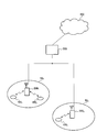
- FIG. 1 is a diagram showing a radio communication system having radio base station apparatuses and mobile terminal apparatuses according to an embodiment of the present invention.
- the wireless communication system is a system to which, for example, E-UTRA (Evolved UTRA and UTRAN) is applied.
- the radio communication system includes a base station apparatus (eNB: eNodeB) 200 (200 1 , 200 2 ... 200 l , l is an integer satisfying l> 0), and a plurality of mobile terminals (UE) communicating with the base station apparatus 200 100 n (100 1 , 100 2 , 100 3 ,... 100 n , n is an integer of n> 0).
- Base station apparatus 200 is connected to an upper station, for example, access gateway apparatus 300, and access gateway apparatus 300 is connected to core network 400.
- the mobile terminal 100 n communicates with the base station apparatus 200 by E-UTRA in the cell 50 (50 1 , 50 2 ). Although the present embodiment shows two cells, the present invention can be similarly applied to three or more cells. In addition, since each mobile terminal (100 1 , 100 2 , 100 3 ,... 100 n ) has the same configuration, function, and state, the following description will be given as the mobile terminal 100 n unless otherwise specified. .
- OFDM Orthogonal Frequency Division Multiple Access
- SC-FDMA Single Carrier Frequency Division Multiple Access
- OFDM is a multi-carrier transmission scheme that performs communication by dividing a frequency band into a plurality of narrow frequency bands (subcarriers) and mapping data to each subcarrier.
- SC-FDMA is a single carrier transmission scheme in which frequency bands are divided for each terminal, and a plurality of terminals use different frequency bands to reduce interference between terminals.
- a physical downlink shared channel (PDSCH) shared by each mobile terminal 100 n and a physical downlink control channel (PDCCH) are used.
- the physical downlink control channel is also called a downlink L1 / L2 control channel.
- User data that is, a normal data signal is transmitted through the physical downlink shared channel.
- downlink scheduling information DL Scheduling Information
- acknowledgment information ACK / NACK
- uplink scheduling grant UL Scheduling Grant
- TPC command Transmission Power Control Command
- the downlink scheduling information includes, for example, the ID of a user who performs communication using a physical downlink shared channel, and information on the transport format of the user data, that is, data size, modulation scheme, retransmission control (HARQ: Hybrid ARQ) And downlink resource block allocation information.
- HARQ Hybrid ARQ
- the uplink scheduling grant includes, for example, the ID of a user who performs communication using the physical uplink shared channel, information on the transport format of the user data, that is, information on the data size and modulation scheme, This includes resource block allocation information, information related to uplink shared channel transmission power, and the like.
- the uplink resource block corresponds to a frequency resource and is also called a resource unit.
- the delivery confirmation information (ACK / NACK) is delivery confirmation information related to the uplink shared channel.
- the contents of the acknowledgment information are expressed by either an acknowledgment (ACK: Acknowledgement) indicating that the transmission signal has been properly received or a negative acknowledgment (NACK: Negative Acknowledgement) indicating that the transmission signal has not been properly received. Is done.
- a physical uplink shared channel (PUSCH) shared by each mobile terminal 100 n and a physical uplink control channel (PUCCH) are used.
- User data that is, a normal data signal is transmitted through the physical uplink shared channel.
- the physical uplink control channel transmits downlink quality information and physical downlink shared channel delivery confirmation information to be used for downlink shared physical channel scheduling processing, adaptive modulation / demodulation, and encoding processing.
- the uplink shared channel resource allocation means that communication may be performed using an uplink shared channel in a subsequent subframe using a physical downlink control channel of a certain subframe. Means to notify the mobile terminal.
- the mobile terminal 100 n communicates with the optimal base station apparatus.
- the mobile terminal 100 1, 100 2 communicates with the base station apparatus 200 1
- the mobile terminal 100 3 is in communication with the base station apparatus 200 2.
- the base station apparatus 200 when performing MU-MIMO transmission, as shown in FIG. 2, the base station apparatus 200 spatially multiplexes and transmits data to a plurality of mobile terminals 100a and 100b. That is, base station apparatus 200 has antennas 200a and 200b, and transmits signals from antenna 200a to mobile terminal 100a (stream 1), and transmits signals from antenna 200b to mobile terminal 100b (stream 2). . At this time, the signal transmitted from the antenna 200a and the signal transmitted from the antenna 200b are spatially multiplexed.
- the base station apparatus 200 transmits a CSI reference signal (Reference Signal: RS) (CSI-RS) to the mobile terminals 100a and 100b in the downlink, and the mobile terminals 100a and 100b receive the spatial channel state. Is transmitted to the base station apparatus 200 in the uplink. Then, base station apparatus 200 generates a transmission weight based on the fed back PMI.
- RS Reference Signal
- CoMP transmission is being studied as a measure for improving reception quality of cell edge users.
- This CoMP transmission is roughly classified into joint processing (JP) and coordinated scheduling / beamforming (CS / CB).
- JP is further classified into joint transmission (JT) and dynamic cell selection (DCS).
- JP of CoMP transmission transmits a PDCCH signal only from the base station apparatus 200 1 of the serving cell, the data and the reference signal for demodulation (Demodulation Reference Signal: DM-RS ) and is a method capable of transmitting also the base station apparatus 200 2, 200 3 of the base station apparatus 200 1 other than the neighboring cell of the serving cell.
- JT is the data and the DM-RS and the base station apparatus 200 1 of the serving cell, a method of simultaneously transmitted from the base station apparatus 200 2, 200 3 neighboring cells (Fig. 3 (a)), DCS is In this method, data and DM-RS are transmitted from the base station apparatus (base station apparatus 200 2 in FIG. 3B) having the best spatial channel state at the time of transmission. DCS is particularly useful for improving the throughput of cell edge users.
- CoMP transmission of CS / CB transmits a PDCCH signal and data and DM-RS only from the base station apparatus 200 1 of the serving cell, the base station apparatus 200 2 in the peripheral cell, 200 3 Is a method of increasing the received SINR of the mobile terminal by scheduling or beamforming. That is, when the signal transmitted from the base station apparatus 200 1 of the serving cell, the base station apparatus 200 2 of neighboring cells, 200 as 3 not signaled from the resource block (Resource Block: RB) to select a beam forming ( The base station devices 200 2 and 200 3 do not transmit signals to the mobile terminal 100a, but transmit signals to the other mobile terminals 100c and 100d, respectively).
- CS / CB is also particularly useful for improving the throughput of cell edge users.
- CQI and PMI are defined as CSI feedback information to be fed back to the radio base station apparatus.
- This CSI feedback information is mainly information for supporting SU-MIMO.
- a report mode corresponding to a combination of feedback bandwidths of CQI and PMI is defined. This report mode is given by higher layer signaling for each mobile terminal device.
- the present inventors propose to change the definition of CSI feedback information in order to support MU-MIMO transmission and CoMP transmission.
- the present inventors propose to define (extend) CSI feedback information optimal for the report mode from such a viewpoint.
- CSI feedback information is defined as a combination of CQI and spatial channel information.
- Spatial channel information is a concept that extends PMI
- PMI is a type of spatial channel information.
- the level of extension of CSI feedback information changes according to the information amount of spatial channel information for MU-MIMO transmission, for example. That is, it is assumed that the greater the amount of spatial channel information for MU-MIMO transmission, the higher the extension level.
- the large amount of information of the spatial channel information for MU-MIMO transmission means that, for example, the number of PMI bits is increased, not direct (implicit) feedback information such as PMI, but direct ( explicit) This means using feedback information (eg, direct channel matrix or covariance matrix).
- the level of extension of CSI feedback information varies depending on the CoMP transmission mode (CS / CB, DCS, JT). That is, when the CoMP transmission form is CS / CB, the extension level is low, when the CoMP transmission form is DCS, the extension level is higher than when CS / CB, and the CoMP transmission form is JT. The expansion level is higher than in the case of DCS.
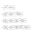
- FIG. 4 is a diagram for explaining a report mode of CSI feedback information in the wireless communication method according to the present invention.
- the CSI feedback information includes a wideband CQI in which the feedback bandwidth is a wideband (entire system bandwidth), a feedback bandwidth is a subband (a part of system bandwidth (for example, component carrier)), and the mobile terminal device There is a subband CQI to be selected, and a subband CQI notified from an upper layer whose feedback bandwidth is a subband.
- the spatial channel information there is no feedback (no MIMO transmission), wide bandwidth spatial channel information in which the feedback bandwidth is wideband, and the averaging period of the spatial channel information is short, and the feedback bandwidth is wide.
- Wideband spatial channel information which is a band and the spatial channel information averaging period is long, and subband spatial channel information whose feedback bandwidth is a subband and whose spatial channel information is averaged in a short period There is subband spatial channel information in which the feedback bandwidth is a subband and the averaging period of the spatial channel information is long.
- the report mode in the wireless communication method according to the present invention is defined by a combination of the CQI and the spatial channel information.
- the report mode shown in FIG. 4 is an example, and the report mode in the present invention is not limited to FIG.
- mode 3-1 that is, subband CQI (upper layer), wideband spatial channel information
- the antenna correlation of the radio base station apparatus is relatively high.
- mode 2-0 report mode indicated by (B), ie, subband CQI (UE selection), no feedback
- mode 3-0 report mode indicated by (B), ie, subband CQI (upper layer)
- No feedback is the same as the feedback information reporting mode in the LTE system.
- mode 1-2 report mode shown in (C), ie, wideband CQI, subband spatial channel information (short-term average)
- mode 2-2 report mode shown in (C), ie, subband In the case of CQI (UE selection) and subband spatial channel information (short-term average)
- CQI UE selection
- subband spatial channel information short-term average
- the CSI feedback information is a combination of a subband CQI and a wideband covariance matrix, as shown in FIG. Since the covariance matrix is direct feedback information, the spatial channel information for MU-MIMO transmission is expanded.
- mode 3-1 when supporting CoMP transmission of CS / CB, spatial channel information of neighboring cells other than the serving cell is also required. Therefore, as shown in FIG. A combination of the subband CQI of (# 1), the wideband covariance matrix of the serving cell (# 1), and the wideband covariance matrix of the peripheral cells (# 2).
- the CSI feedback information is shown in FIG. c), the subband CQI of the serving cell (# 1), the wideband covariance matrix of the serving cell (# 1), the subband CQI of the neighboring cell (# 2 %), and the neighboring cell (# 2 ). ) Wideband covariance matrix.
- feedback information of a higher extension level includes feedback information of a lower extension level. That is, the format shown in FIG. 5B includes the format shown in FIG. 5A, and a wideband covariance matrix of peripheral cells (# 2...) Is added. Further, the format shown in FIG. 5C includes the format shown in FIG. 5B, and the subband CQIs of the peripheral cells (# 2...) Are added. The format shown in FIG. 5D includes the format shown in FIG. 5C, and an inter-cell PMI (subband) (assist information) is added.
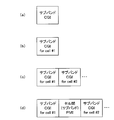
- the CSI feedback information is a combination of subband CQI and wideband PMI, as shown in FIG.
- This feedback information is a format used in the LTE system.
- the CSI feedback information includes the subband CQI of the serving cell (# 1) and the wideband of the serving cell (# 1) as shown in FIG. A combination with the band PMI.
- the CSI feedback information is shown in FIG. c), the subband CQI of the serving cell (# 1), the wideband PMI of the serving cell (# 1), the subband CQI of the neighboring cell (# 2 %), and the neighboring cell (# 2 7) A combination with a wideband PMI.
- the CSI feedback information includes the subband CQI of the serving cell (# 1) and the serving cell (# 1) Wide band PMI, inter-cell PMI (subband), subband CQI of peripheral cell (# 2%), And wideband PMI of peripheral cell (# 2).
- feedback information of a higher extension level includes feedback information of a lower extension level. That is, the format shown in FIG. 6B includes the format shown in FIG.
- the format shown in FIG. 6C includes the format shown in FIG. 6B, and the subband CQI of the peripheral cell (# 2%) And the wideband PMI of the peripheral cell (# 2...) Are added. Yes.
- the format shown in FIG. 6D includes the format shown in FIG. 6C, and an inter-cell PMI (subband) (assist information) is added.
- FIGS. 7 (a) to 7 (d) When the reporting mode shown in FIG. 4 is mode 2-0 or mode 3-0, it is desirable to select a format as shown in FIGS. 7 (a) to 7 (d).
- the formats shown in FIGS. 7A to 7D are formats that are used in the LTE system and have no extension.
- the CSI feedback information is subband CQI as shown in FIG.
- the CSI feedback information is the subband CQI of the serving cell (# 1) as shown in FIG. 7 (b).
- the CSI feedback information is as shown in FIG. A combination of the subband CQI of the serving cell (# 1) and the subband CQI of the neighboring cell (# 2).
- the CSI feedback information includes the sub-band CQI of the serving cell (# 1), the inter-cell PMI (sub-band), and the neighboring cells as shown in FIG. A combination with the subband CQI of (# 2).
- feedback information of a higher extension level includes feedback information of a lower extension level. That is, the format shown in FIG. 7B includes the format shown in FIG. Further, the format shown in FIG. 7C includes the format shown in FIG. 7B, and the subband CQIs of the peripheral cells (# 2...) Are added. The format shown in FIG. 7D includes the format shown in FIG. 7C, and an inter-cell PMI (subband) (assist information) is added.
- an inter-cell PMI subband
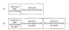
- the CSI feedback information includes wideband CQI or A combination of subband CQI and subband direct channel matrix. Since the direct channel matrix is direct feedback information, the spatial channel information for MU-MIMO transmission is expanded.
- the CSI feedback information is shown in FIG. ), The combination of the wideband CQI or subband CQI of the serving cell (# 1), the subband direct channel matrix of the serving cell (# 1), and the subband direct channel matrix of the neighboring cell (# 2%) And
- feedback information of a higher extension level includes feedback information of a lower extension level. That is, the format shown in FIG. 8B includes the format shown in FIG. 8A, and a subband direct channel matrix of peripheral cells (# 2...) Is added.
- a format of feedback information of a high extension level is used, it becomes possible to serve as a format of feedback information of a lower extension level.
- CQI (SINR) and covariance matrix are fed back from the mobile terminal (ST11).
- a precoding weight is generated using this CQI (ST12).
- the covariance matrix which is direct spatial channel information, is multiplied by the precoding gain, so that the SINR after multiplication is different from the fed back CQI (SINR). For this reason, CQI (SINR) is recalculated for correction by the precoding gain multiplication (ST13).
- CoMP reporting set that is, the set of cells cooperating with CoMP.
- (1-1) CQI includes the gain that is the best precoding weight, and PMI that is indirect spatial channel feedback is used. This is adopted in the LTE system.
- (1-2) CQI may be generated without considering the precoding weight. For example, the average channel gain of a plurality of antennas may be used. This can be a candidate for direct spatial channel feedback.
- Intracell interference in MU-MIMO transmission is not considered as interference. This is adopted in the LTE system. On the other hand, considering intra-cell interference in MU-MIMO transmission as interference. In this case, the quantization error is approximated with intra-cell interference.
- (3-1) Not considering interference from cells in a set of cells cooperating with CoMP.
- (3-2) interference in the absence of precoding effect may be considered as from a cell in a set of cells cooperating with CoMP. For example, using the average channel gain of multiple antennas Is mentioned.
- (3-3) treating cell interference in a set of cells cooperating with CoMP and cell interference not cooperating with CoMP in the same way can be mentioned.
- (3-1) and (3-2) are preferable in consideration of the precoding weight and the schedule result.
- FIG. 10 is a diagram showing a configuration of the radio base station apparatus according to the embodiment of the present invention.
- the radio base station apparatus shown in FIG. 10 multiplexes a plurality of antennas 1001, a duplexer 1002 for switching transmission / reception, transmission signal processing units 1003 for the number of antennas, and demodulation reference signals (DM-RS) into transmission data.
- DM-RS multiplexing section 1004 transmission data generating section 1005 for generating transmission data, control information receiving section 1006 for receiving uplink signal control information, and transmission weight generation for generating transmission weights based on spatial channel information It is mainly composed of a part 1007.
- Each of the transmission signal processing units 1003 includes a multiplier 10034 that multiplies the transmission signal by a transmission weight, a CSI-RS multiplexing unit 10033 that multiplexes a reference signal (CSI-RS) for channel state information to the transmission signal, and a multiplexed signal
- a multiplier 10034 that multiplies the transmission signal by a transmission weight
- a CSI-RS multiplexing unit 10033 that multiplexes a reference signal (CSI-RS) for channel state information to the transmission signal
- CSI-RS reference signal
- An IFFT unit 10032 that performs an inverse fast Fourier transform (IFFT) operation on the signal
- CP addition unit 10031 that adds a CP (Cyclic Prefix) to the signal after the IFFT.
- the transmission data generation unit 1005 generates transmission data from at least downlink transmission data, a report mode corresponding to a bandwidth for feedback of feedback information, and an extended level of feedback information.
- the feedback information includes channel quality information (CQI) and spatial channel information.
- Transmission data generation section 1005 outputs the transmission data to DM-RS multiplexing section 1004.
- DM-RS multiplexing section 1004 multiplexes transmission data and DM-RS and outputs the multiplexed data to each transmission signal processing section 1003.
- the multiplier 10034 of each transmission signal processing unit 1003 multiplies transmission data by a transmission weight.
- the transmission signal multiplied by the transmission weight is output to CSI-RS multiplexing section 10033.
- CSI-RS multiplexing section 10033 multiplexes a channel state information reference signal (CSI-RS) to transmission data multiplied by a transmission weight.
- CSI-RS multiplexing section 10033 outputs the multiplexed transmission data to IFFT section 10032.
- CSI-RS channel state information reference signal
- the IFFT unit 10032 performs IFFT on the multiplexed transmission data and converts it into a time domain signal.
- IFFT section 10032 outputs the signal after IFFT to CP adding section 10031.
- CP adding section 10031 adds a CP to the signal after IFFT.
- the signal added with CP by each transmission signal processing section 1003 is MU-MIMO-transmitted to each mobile terminal on the downlink from each antenna 1001 via the duplexer 1002.
- control information receiving unit 1006 receives the uplink reception data and the control information, and outputs the control information (feedback information) to the transmission weight generation unit 1007 and the transmission data generation unit 1005. That is, control information receiving section 1006 outputs the spatial channel information of feedback information to transmission weight generating section 1007 and outputs the CQI of feedback information to transmission data generating section 1005.
- the feedback information fed back from the mobile terminal has a format as shown in FIGS. 5 to 8, for example, depending on the report mode. That is, the feedback information is expanded at a level corresponding to the report mode.
- the report mode is mode 3-1 in FIG. 4
- an extended format as shown in FIGS. 5A to 5D or 6A to 6D is used.
- the reporting mode is mode 1-2 or mode 2-2 in FIG. 4
- an extended format as shown in FIGS. 8A and 8B is used.
- the report mode is mode 2-0 or mode 3-0 in FIG. 4
- the formats as shown in FIGS. 7A to 7D are used.
- the format is selected according to the CoMP transmission mode.
- the transmission data generation unit 1005 performs adaptive modulation / demodulation and encoding processing (AMC) using the CQI from the control information reception unit 1006 in the generation of transmission data.
- transmission weight generation section 1007 generates a transmission weight using the spatial channel information from control information reception section 1006.
- the spatial channel information is explicit information, for example, a covariance matrix
- a transmission weight is generated by multiplying the covariance matrix by a precoding gain.
- the spatial channel information is implicit information, for example, PMI
- a transmission weight corresponding to PMI is selected from the codebook.
- FIG. 11 is a diagram showing a configuration of the mobile terminal apparatus according to the embodiment of the present invention.
- the mobile terminal apparatus shown in FIG. 11 includes an antenna 1101, a duplexer 1102 that switches between transmission and reception, a CP removal unit 1103 that removes the CP from the received signal, and an FFT unit that performs fast Fourier transform (FFT) on the received signal.
- FFT fast Fourier transform
- a CSI estimation unit 1105 that estimates CSI using CSI-RS, a channel estimation unit 1106 that estimates channels using DM-RS, and a demodulation / decoding that demodulates and decodes received data using channel estimation values Unit 1107, CSI feedback information generating unit 1108 for generating CSI feedback information from the CSI estimated value and the report mode / extension level, uplink transmission data multiplexing unit 1109 for multiplexing uplink transmission data and CSI feedback information, and after multiplexing Discrete Fourier Transform (DFT: Discrete Fourie) r (Transform)
- DFT Discrete Fourier Transform
- a DFT unit 1110 that performs an operation
- an IFFT unit 1111 that performs an IFFT operation on transmission data after the DFT
- a CP addition unit 1112 that adds a CP to the signal after the IFFT.
- CSI estimator 1105 is provided for cells that cooperate in CoMP transmission.
- the signal transmitted from the base station apparatus in the downlink is received by the receiving unit via each antenna 1101.
- CP removing section 1103 of the receiving section removes a portion corresponding to CP from the received signal and extracts an effective signal portion.
- CP removing section 1103 outputs the signal after CP removal to FFT section 1104.
- the FFT unit 1104 performs FFT on the signal after CP removal and converts it to a frequency domain signal.
- FFT section 1104 outputs the signal after FFT to CSI estimating section 1105, channel estimating section 1106, and demodulation / decoding section 1107.
- CSI-RS is sent to CSI estimating section 1105
- DM-RS is sent to channel estimating section 1106, and received data is sent to demodulating / decoding section 1107.
- the CSI estimation unit 1105 estimates channel fluctuation using CSI-RS, and compensates the estimated channel fluctuation to obtain CSI (CQI, spatial channel information). Also, CSI estimation section 1105 outputs the obtained CSI (CQI, spatial channel information) to CSI feedback information generation section 1108. That is, CSI estimation units 1105 for cells cooperating with CoMP transmission output CSI (CQI, spatial channel information) compensated for channel variations to CSI feedback information generation unit 1108, respectively.
- Channel estimation section 1106 estimates channel fluctuation using DM-RS, and outputs the estimated channel fluctuation result to demodulation / decoding section 1107.
- Demodulation / decoding section 1107 compensates for channel fluctuation estimated by channel estimation section 1106 to obtain downlink received data.
- This downlink reception data includes a report mode and an extension level. This report mode and extension level are sent to the CSI feedback information generation unit 1108.
- the CSI feedback information generation unit 1108 generates CSI feedback information corresponding to the report mode and the extension level. CSI feedback information generation section 1108 outputs this CSI feedback information to uplink transmission data multiplexing section 1109.
- the CSI feedback information has a format as shown in FIGS. 5 to 8, for example, depending on the report mode. That is, the feedback information is expanded at a level corresponding to the report mode. For example, when the report mode is mode 3-1 in FIG. 4, an extended format as shown in FIGS. 5A to 5D or 6A to 6D is used. When the reporting mode is mode 1-2 or mode 2-2 in FIG. 4, an extended format as shown in FIGS. 8A and 8B is used. When the report mode is mode 2-0 or mode 3-0 in FIG. 4, the formats as shown in FIGS. 7A to 7D are used. In the formats shown in FIGS. 5 to 8, the format is selected according to the CoMP transmission mode.
- the uplink transmission data multiplexing unit 1109 multiplexes CSI feedback information with the uplink transmission data.
- Uplink transmission data multiplexing section 1109 outputs the multiplexed transmission data to DFT section 1110.
- the DFT unit 1110 DFTs the multiplexed transmission data and outputs the DFT transmission data to the IFFT unit 1111.
- IFFT section 1111 performs IFFT on the transmission data after DFT and converts it into a signal in the time domain.
- IFFT section 1111 outputs the signal after IFFT to CP adding section 1112.
- CP adding section 1112 adds a CP to the signal after IFFT.
- the CP-added signal is transmitted from the antenna 1101 via the duplexer 1102 to the base station apparatus in the uplink.
- the transmission data generation unit 1005 of the base station apparatus generates downlink transmission data including a report mode corresponding to a bandwidth for feedback of feedback information and an extended level of feedback information.
- the feedback information includes CQI and spatial channel information.
- the downlink transmission data including the report mode and the extension level is multiplexed with DM-RS and CSI-RS and transmitted to the mobile terminal on the downlink.
- the mobile terminal receives the downlink signal including the report mode and the extension level.
- the report mode and the extension level transmitted in the higher layer signaling among the downlink signals are sent to the CSI feedback information generation unit 1108.
- the CSI feedback information generation unit 1108 generates feedback information corresponding to the report mode and the extension level.
- the CSI feedback information has a format as shown in FIGS. 5 to 8, for example, according to the report mode.
- the mobile terminal transmits uplink transmission data including feedback information in such a format to the base station apparatus on the uplink.
- the base station apparatus receives uplink transmission data including feedback information transmitted on the uplink, performs adaptive modulation / demodulation and coding processing (AMC) using CQI of feedback information, and uses spatial channel information of feedback information. To generate a transmission weight.
- AMC adaptive modulation / demodulation and coding processing
- MU-MIMO transmission and CoMP transmission in the LTE-A system are sufficiently supported. can do.
- the present invention is not limited to the above embodiment, and can be implemented with various modifications.
- the report mode of the combination of CQI and spatial channel information as shown in FIG. 4 has been described.
- the present invention is not limited to this, and other combinations of CQI and spatial channel information are available. The same can be applied to the reporting mode.
- the formats as shown in FIGS. 5 to 8 have been described.
- the present invention is not limited to this, and feedback information formats other than the formats shown in FIGS. The same applies when used.
- the number of processing units and the processing procedure in the above description can be changed as appropriate without departing from the scope of the present invention.
- Each element shown in the figure represents a function, and each functional block may be realized by hardware or software. Other modifications can be made without departing from the scope of the present invention.
- the present invention is useful for an LTE-A system radio base station apparatus, mobile terminal apparatus, and radio communication method.
Abstract
Description
図1は、本発明の実施の形態に係る無線基地局装置及び移動端末装置を有する無線通信システムを示す図である。 Hereinafter, embodiments of the present invention will be described in detail with reference to the accompanying drawings.
FIG. 1 is a diagram showing a radio communication system having radio base station apparatuses and mobile terminal apparatuses according to an embodiment of the present invention.
下りリンクについては、各移動端末100nで共有される物理下りリンク共有チャネル(PDSCH:Physical Downlink Shared Channel)と、物理下りリンク制御チャネル(PDCCH:Physical Downlink Control Channel)とが用いられる。物理下りリンク制御チャネルは下りL1/L2制御チャネルとも呼ばれる。上記物理下りリンク共有チャネルにより、ユーザデータ、すなわち、通常のデータ信号が伝送される。また、物理下りリンク制御チャネルにより、下りスケジューリング情報(DL Scheduling Information)、送達確認情報(ACK/NACK)、上りスケジューリンググラント(UL Scheduling Grant)、TPCコマンド(Transmission Power Control Command)などが伝送される。下りスケジューリング情報には、例えば、物理下りリンク共有チャネルを用いて通信を行うユーザのIDや、そのユーザデータのトランスポートフォーマットの情報、すなわち、データサイズ、変調方式、再送制御(HARQ:Hybrid ARQ)に関する情報や、下りリンクのリソースブロックの割り当て情報などが含まれる。 Here, communication channels in E-UTRA will be described.
For the downlink, a physical downlink shared channel (PDSCH) shared by each
まず、基地局装置の送信データ生成部1005において、フィードバック情報をフィードバックする帯域幅に応じた報告モード及びフィードバック情報の拡張レベルを含む下り送信データを生成する。フィードバック情報は、CQI及び空間チャネル情報を含む。そして、報告モード及び拡張レベルを含む下り送信データは、DM-RS及びCSI-RSが多重されて下りリンクで移動端末に送信される。 A radio communication method in the radio base station apparatus and mobile terminal apparatus having the above configuration will be described.
First, the transmission
Claims (14)
- チャネル品質情報及び空間チャネル情報を含むフィードバック情報をフィードバックする帯域幅に応じた報告モード、並びに前記フィードバック情報の拡張レベルを含む下り送信データを生成する下り送信データ生成手段と、前記下り送信データとフィードバック情報用の参照信号とを多重する多重手段と、を具備することを特徴とする無線基地局装置。 A report mode corresponding to a bandwidth for feeding back feedback information including channel quality information and spatial channel information, downlink transmission data generating means for generating downlink transmission data including an extension level of the feedback information, the downlink transmission data and feedback A radio base station apparatus comprising: multiplexing means for multiplexing information reference signals.
- 前記拡張レベルは、マルチユーザMIMO伝送用の空間チャネル情報の情報量に応じて変わることを特徴とする請求項1記載の無線基地局装置。 The radio base station apparatus according to claim 1, wherein the enhancement level changes according to an information amount of spatial channel information for multi-user MIMO transmission.
- 前記拡張レベルは、CoMP送信の形態に応じて変わることを特徴とする請求項1記載の無線基地局装置。 The radio base station apparatus according to claim 1, wherein the extension level changes according to a CoMP transmission mode.
- 前記下り送信データ生成手段は、フィードバック情報に含まれるチャネル品質情報に基づく適応変復調及び符号化処理で下り送信データを生成することを特徴とする請求項1記載の無線基地局装置。 The radio base station apparatus according to claim 1, wherein the downlink transmission data generating means generates downlink transmission data by adaptive modulation / demodulation and encoding processing based on channel quality information included in feedback information.
- フィードバック情報に含まれる空間チャネル情報に基づいて送信ウェイトを生成する送信ウェイト生成手段を具備することを特徴とする請求項1記載の無線基地局装置。 The radio base station apparatus according to claim 1, further comprising transmission weight generation means for generating a transmission weight based on spatial channel information included in the feedback information.
- より高い拡張レベルのフィードバック情報が、より低い拡張レベルのフィードバック情報を包含することを特徴とする請求項1記載の無線基地局装置。 The radio base station apparatus according to claim 1, wherein the feedback information of a higher extension level includes feedback information of a lower extension level.
- チャネル品質情報及び空間チャネル情報を含むフィードバック情報をフィードバックする帯域幅に応じた報告モード、並びに前記フィードバック情報の拡張レベルを含む下りリンク信号を受信する受信手段と、前記報告モード及び前記拡張レベルに対応するフィードバック情報を生成するフィードバック情報生成手段と、を具備することを特徴とする移動端末装置。 Corresponding to the report mode corresponding to the bandwidth for feeding back feedback information including channel quality information and spatial channel information, and a receiving means for receiving a downlink signal including an extension level of the feedback information, and the report mode and the extension level And a feedback information generating means for generating feedback information to be transmitted.
- 前記拡張レベルは、マルチユーザMIMO伝送用の空間チャネル情報の情報量に応じて変わることを特徴とする請求項7記載の移動端末装置。 The mobile terminal apparatus according to claim 7, wherein the enhancement level changes according to an information amount of spatial channel information for multi-user MIMO transmission.
- 前記拡張レベルは、CoMP送信の形態に応じて変わることを特徴とする請求項7記載の移動端末装置。 The mobile terminal apparatus according to claim 7, wherein the extension level changes according to a CoMP transmission mode.
- より高い拡張レベルのフィードバック情報が、より低い拡張レベルのフィードバック情報を包含することを特徴とする請求項7記載の移動端末装置。 The mobile terminal apparatus according to claim 7, wherein feedback information of a higher extension level includes feedback information of a lower extension level.
- 無線基地局装置において、チャネル品質情報及び空間チャネル情報を含むフィードバック情報をフィードバックする帯域幅に応じた報告モード、並びに前記フィードバック情報の拡張レベルを含む下り送信データを生成する工程と、前記下り送信データとフィードバック情報用の参照信号とを多重して移動端末装置に送信する工程と、前記移動端末装置において、前記報告モード及び前記拡張レベルを含む下りリンク信号を受信する工程と、前記報告モード及び前記拡張レベルに対応するフィードバック情報を生成して前記無線基地局装置に送信する工程と、を具備することを特徴とする無線通信方法。 In the radio base station apparatus, a step of generating downlink transmission data including a report mode corresponding to a bandwidth for feeding back feedback information including channel quality information and spatial channel information, and an extension level of the feedback information, and the downlink transmission data And a reference signal for feedback information are multiplexed and transmitted to the mobile terminal apparatus, the mobile terminal apparatus receives a downlink signal including the report mode and the enhancement level, the report mode and the And a step of generating feedback information corresponding to an extension level and transmitting the feedback information to the radio base station apparatus.
- 前記拡張レベルは、マルチユーザMIMO伝送用の空間チャネル情報の情報量に応じて変わることを特徴とする請求項11記載の無線通信方法。 The wireless communication method according to claim 11, wherein the extension level changes according to an information amount of spatial channel information for multi-user MIMO transmission.
- 前記拡張レベルは、CoMP送信の形態に応じて変わることを特徴とする請求項11記載の無線通信方法。 The wireless communication method according to claim 11, wherein the extension level varies depending on a CoMP transmission mode.
- より高い拡張レベルのフィードバック情報が、より低い拡張レベルのフィードバック情報を包含することを特徴とする請求項11記載の無線通信方法。 The wireless communication method according to claim 11, wherein the feedback information of a higher extension level includes feedback information of a lower extension level.
Priority Applications (3)
| Application Number | Priority Date | Filing Date | Title |
|---|---|---|---|
| CN2010800444591A CN102550072A (en) | 2009-10-05 | 2010-10-05 | Wireless base station device, mobile terminal device and wireless communication method |
| EP10821998.1A EP2487953A4 (en) | 2009-10-05 | 2010-10-05 | Wireless base station device, mobile terminal device and wireless communication method |
| US13/498,917 US9276651B2 (en) | 2009-10-05 | 2010-10-05 | Radio base station apparatus, mobile terminal apparatus and radio communication method |
Applications Claiming Priority (2)
| Application Number | Priority Date | Filing Date | Title |
|---|---|---|---|
| JP2009-231962 | 2009-10-05 | ||
| JP2009231962A JP5210278B2 (en) | 2009-10-05 | 2009-10-05 | Radio base station apparatus, mobile terminal apparatus and radio communication method |
Publications (1)
| Publication Number | Publication Date |
|---|---|
| WO2011043328A1 true WO2011043328A1 (en) | 2011-04-14 |
Family
ID=43856781
Family Applications (1)
| Application Number | Title | Priority Date | Filing Date |
|---|---|---|---|
| PCT/JP2010/067435 WO2011043328A1 (en) | 2009-10-05 | 2010-10-05 | Wireless base station device, mobile terminal device and wireless communication method |
Country Status (5)
| Country | Link |
|---|---|
| US (1) | US9276651B2 (en) |
| EP (1) | EP2487953A4 (en) |
| JP (1) | JP5210278B2 (en) |
| CN (2) | CN103957043B (en) |
| WO (1) | WO2011043328A1 (en) |
Cited By (16)
| Publication number | Priority date | Publication date | Assignee | Title |
|---|---|---|---|---|
| CN102638840A (en) * | 2012-03-21 | 2012-08-15 | 新邮通信设备有限公司 | Radio resource management measurement method and system in long term evolution based on coordinated multiple points |
| WO2012144645A1 (en) * | 2011-04-22 | 2012-10-26 | 株式会社エヌ・ティ・ティ・ドコモ | Method for configuring coordinated multipoint transmission |
| CN102957470A (en) * | 2011-08-16 | 2013-03-06 | 上海贝尔股份有限公司 | Method and system for channel feedbacks in wireless communication |
| WO2013024350A3 (en) * | 2011-08-15 | 2013-05-02 | Alcatel Lucent | Methods and apparatuses for channel measurement and feedback of multi-dimensional antenna array |
| WO2013069537A1 (en) * | 2011-11-07 | 2013-05-16 | 株式会社エヌ・ティ・ティ・ドコモ | Wireless communication system, wireless base station, user equipment, and wireless communication method |
| WO2013108901A1 (en) * | 2012-01-19 | 2013-07-25 | 京セラ株式会社 | Base station and communication control method |
| CN103297991A (en) * | 2012-03-02 | 2013-09-11 | 中兴通讯股份有限公司 | Method and device for enhancing cell edge covering |
| WO2013140782A1 (en) * | 2012-03-20 | 2013-09-26 | Sharp Kabushiki Kaisha | Channel quality indicator feedback method and user equipment |
| WO2013141338A1 (en) * | 2012-03-23 | 2013-09-26 | 株式会社エヌ・ティ・ティ・ドコモ | Wireless communication system, user terminal, wireless base station device and wireless communication method |
| WO2013149527A1 (en) * | 2012-04-01 | 2013-10-10 | 华为技术有限公司 | Measurement method and apparatus |
| WO2014021153A1 (en) * | 2012-07-30 | 2014-02-06 | シャープ株式会社 | Communication system, communication method, base station device and mobile station device |
| CN104285188A (en) * | 2012-05-17 | 2015-01-14 | 华为技术有限公司 | System and method for adaptive downlink comp operation |
| JP2015513257A (en) * | 2012-02-23 | 2015-04-30 | エレクトロニクス アンド テレコミュニケーションズ リサーチ インスチチュートElectronics And Telecommunications Research Institute | Multiple-input multiple-output communication method in large-scale antenna system |
| RU2581037C2 (en) * | 2011-05-02 | 2016-04-10 | Нтт Докомо, Инк. | Method for reporting channel state information, radio base station, user terminal and radio communication system |
| RU2745274C1 (en) * | 2017-11-16 | 2021-03-23 | Фраунхофер-Гезелльшафт Цур Фердерунг Дер Ангевандтен Форшунг Е.Ф. | Allocation of resources for direct communication in a wireless network |
| US20220311484A1 (en) * | 2011-04-19 | 2022-09-29 | Sun Patent Trust | Pre-coding method and pre-coding device |
Families Citing this family (59)
| Publication number | Priority date | Publication date | Assignee | Title |
|---|---|---|---|---|
| US8917614B2 (en) | 2010-02-05 | 2014-12-23 | Qualcomm Incorporated | Resource allocation and transmission for coordinated multi-point transmission |
| JP5666871B2 (en) * | 2010-10-12 | 2015-02-12 | シャープ株式会社 | Wireless communication system, base station apparatus, and wireless communication method |
| US20140023033A1 (en) * | 2011-04-13 | 2014-01-23 | Lg Electronics Inc. | Method and apparatus for transceiving channel status information and transceiver |
| CN102149130B (en) | 2011-04-22 | 2014-01-01 | 电信科学技术研究院 | Method, device and system for reporting channel quality indicator |
| CN102857934B (en) | 2011-06-28 | 2017-04-26 | 索尼公司 | Method and device for selecting cooperation sets |
| CN102857277B (en) * | 2011-06-29 | 2017-05-10 | 夏普株式会社 | Channel state information feedback method and user device |
| CN103907389B (en) * | 2011-11-04 | 2018-09-21 | 英特尔公司 | Cooperate with the link circuit self-adapting in multipoint system |
| JP5918505B2 (en) * | 2011-11-07 | 2016-05-18 | 株式会社Nttドコモ | Radio communication system, radio base station apparatus, user terminal, and radio communication method |
| CN103220079B (en) | 2012-01-20 | 2018-05-25 | 索尼公司 | For determining method, base station, user equipment and the communication system of transmission set |
| US9451488B2 (en) | 2012-01-20 | 2016-09-20 | Lg Electronics Inc. | Method and apparatus for channel state information feedback in wireless communication system |
| US9571244B2 (en) | 2012-01-26 | 2017-02-14 | Sony Corporation | Wireless communication apparatus, wireless communication method, and wireless communication system |
| JP5923786B2 (en) * | 2012-03-16 | 2016-05-25 | シャープ株式会社 | Base station apparatus and communication method |
| JP5878406B2 (en) * | 2012-03-23 | 2016-03-08 | 株式会社Nttドコモ | Radio communication system, user terminal, radio base station apparatus, and radio communication method |
| CN103391181B (en) * | 2012-05-11 | 2017-05-10 | 株式会社日立制作所 | Method for transmitting data to terminal from base station, base station device and central control server |
| US8767862B2 (en) | 2012-05-29 | 2014-07-01 | Magnolia Broadband Inc. | Beamformer phase optimization for a multi-layer MIMO system augmented by radio distribution network |
| US8861635B2 (en) | 2012-05-29 | 2014-10-14 | Magnolia Broadband Inc. | Setting radio frequency (RF) beamformer antenna weights per data-stream in a multiple-input-multiple-output (MIMO) system |
| US8644413B2 (en) | 2012-05-29 | 2014-02-04 | Magnolia Broadband Inc. | Implementing blind tuning in hybrid MIMO RF beamforming systems |
| US8837650B2 (en) | 2012-05-29 | 2014-09-16 | Magnolia Broadband Inc. | System and method for discrete gain control in hybrid MIMO RF beamforming for multi layer MIMO base station |
| US8971452B2 (en) | 2012-05-29 | 2015-03-03 | Magnolia Broadband Inc. | Using 3G/4G baseband signals for tuning beamformers in hybrid MIMO RDN systems |
| US8842765B2 (en) | 2012-05-29 | 2014-09-23 | Magnolia Broadband Inc. | Beamformer configurable for connecting a variable number of antennas and radio circuits |
| US8811522B2 (en) | 2012-05-29 | 2014-08-19 | Magnolia Broadband Inc. | Mitigating interferences for a multi-layer MIMO system augmented by radio distribution network |
| US8619927B2 (en) | 2012-05-29 | 2013-12-31 | Magnolia Broadband Inc. | System and method for discrete gain control in hybrid MIMO/RF beamforming |
| US9154204B2 (en) | 2012-06-11 | 2015-10-06 | Magnolia Broadband Inc. | Implementing transmit RDN architectures in uplink MIMO systems |
| KR101791396B1 (en) * | 2012-06-18 | 2017-10-27 | 후지쯔 가부시끼가이샤 | Method for feeding back channel state information, ue and system |
| US9723619B2 (en) * | 2012-12-07 | 2017-08-01 | Telefonaktiebolaget Lm Ericsson (Publ) | Coordinated multipoint transmission and reception (CoMP) in a wireless telecommunications network |
| US9343808B2 (en) | 2013-02-08 | 2016-05-17 | Magnotod Llc | Multi-beam MIMO time division duplex base station using subset of radios |
| US8797969B1 (en) * | 2013-02-08 | 2014-08-05 | Magnolia Broadband Inc. | Implementing multi user multiple input multiple output (MU MIMO) base station using single-user (SU) MIMO co-located base stations |
| US8774150B1 (en) | 2013-02-13 | 2014-07-08 | Magnolia Broadband Inc. | System and method for reducing side-lobe contamination effects in Wi-Fi access points |
| US8989103B2 (en) | 2013-02-13 | 2015-03-24 | Magnolia Broadband Inc. | Method and system for selective attenuation of preamble reception in co-located WI FI access points |
| US20140226740A1 (en) | 2013-02-13 | 2014-08-14 | Magnolia Broadband Inc. | Multi-beam co-channel wi-fi access point |
| US9155110B2 (en) | 2013-03-27 | 2015-10-06 | Magnolia Broadband Inc. | System and method for co-located and co-channel Wi-Fi access points |
| US9100968B2 (en) | 2013-05-09 | 2015-08-04 | Magnolia Broadband Inc. | Method and system for digital cancellation scheme with multi-beam |
| US9425882B2 (en) | 2013-06-28 | 2016-08-23 | Magnolia Broadband Inc. | Wi-Fi radio distribution network stations and method of operating Wi-Fi RDN stations |
| US8995416B2 (en) | 2013-07-10 | 2015-03-31 | Magnolia Broadband Inc. | System and method for simultaneous co-channel access of neighboring access points |
| US9578539B1 (en) * | 2013-07-19 | 2017-02-21 | Sprint Spectrum L.P. | Transmitting a data packet over a wireless communication link |
| JP5529327B2 (en) * | 2013-07-22 | 2014-06-25 | 株式会社Nttドコモ | Channel state information notification method, radio base station apparatus, user terminal, and radio communication system |
| US8824596B1 (en) | 2013-07-31 | 2014-09-02 | Magnolia Broadband Inc. | System and method for uplink transmissions in time division MIMO RDN architecture |
| US9497781B2 (en) | 2013-08-13 | 2016-11-15 | Magnolia Broadband Inc. | System and method for co-located and co-channel Wi-Fi access points |
| US9060362B2 (en) | 2013-09-12 | 2015-06-16 | Magnolia Broadband Inc. | Method and system for accessing an occupied Wi-Fi channel by a client using a nulling scheme |
| US9088898B2 (en) | 2013-09-12 | 2015-07-21 | Magnolia Broadband Inc. | System and method for cooperative scheduling for co-located access points |
| US9172454B2 (en) | 2013-11-01 | 2015-10-27 | Magnolia Broadband Inc. | Method and system for calibrating a transceiver array |
| US8891598B1 (en) | 2013-11-19 | 2014-11-18 | Magnolia Broadband Inc. | Transmitter and receiver calibration for obtaining the channel reciprocity for time division duplex MIMO systems |
| US8942134B1 (en) | 2013-11-20 | 2015-01-27 | Magnolia Broadband Inc. | System and method for selective registration in a multi-beam system |
| US8929322B1 (en) | 2013-11-20 | 2015-01-06 | Magnolia Broadband Inc. | System and method for side lobe suppression using controlled signal cancellation |
| US9294177B2 (en) | 2013-11-26 | 2016-03-22 | Magnolia Broadband Inc. | System and method for transmit and receive antenna patterns calibration for time division duplex (TDD) systems |
| US9014066B1 (en) | 2013-11-26 | 2015-04-21 | Magnolia Broadband Inc. | System and method for transmit and receive antenna patterns calibration for time division duplex (TDD) systems |
| US9042276B1 (en) | 2013-12-05 | 2015-05-26 | Magnolia Broadband Inc. | Multiple co-located multi-user-MIMO access points |
| CN104753577B (en) * | 2013-12-31 | 2018-08-21 | 上海诺基亚贝尔股份有限公司 | A kind of multi-user dispatching method and device for down collaboration multi-point |
| US9100154B1 (en) | 2014-03-19 | 2015-08-04 | Magnolia Broadband Inc. | Method and system for explicit AP-to-AP sounding in an 802.11 network |
| US9172446B2 (en) | 2014-03-19 | 2015-10-27 | Magnolia Broadband Inc. | Method and system for supporting sparse explicit sounding by implicit data |
| US9271176B2 (en) | 2014-03-28 | 2016-02-23 | Magnolia Broadband Inc. | System and method for backhaul based sounding feedback |
| WO2015147593A1 (en) | 2014-03-28 | 2015-10-01 | 엘지전자 주식회사 | Method and apparatus for transmitting channel state information in wireless access system supporting machine type communication |
| KR20170091604A (en) | 2014-12-04 | 2017-08-09 | 엘지전자 주식회사 | Method for feeding back partial csis from user equipment in wireless communication system and an apparatus for the same |
| JP6369756B2 (en) | 2015-02-26 | 2018-08-08 | パナソニックIpマネジメント株式会社 | Base station and transmission control method |
| US10863384B2 (en) * | 2016-04-08 | 2020-12-08 | Ntt Docomo, Inc. | Interface method between central aggregate apparatus and extension apparatus, and radio control system |
| CN107888245B (en) * | 2016-09-30 | 2020-10-09 | 电信科学技术研究院 | Beam processing method, base station and mobile terminal |
| JP2017063465A (en) * | 2016-11-09 | 2017-03-30 | 富士通株式会社 | Method, user device and system for feeding back channel state information |
| CN114204968A (en) | 2017-01-06 | 2022-03-18 | 华为技术有限公司 | Signal transmission method and device |
| JP6853284B2 (en) * | 2019-02-13 | 2021-03-31 | 富士通コネクテッドテクノロジーズ株式会社 | How to feed back channel state information, user equipment and systems |
Citations (1)
| Publication number | Priority date | Publication date | Assignee | Title |
|---|---|---|---|---|
| JP2009231962A (en) | 2008-03-19 | 2009-10-08 | Panasonic Electric Works Co Ltd | Information communication device |
Family Cites Families (10)
| Publication number | Priority date | Publication date | Assignee | Title |
|---|---|---|---|---|
| KR101050603B1 (en) * | 2004-06-23 | 2011-07-19 | 삼성전자주식회사 | Packet data transmission / reception apparatus and method using multiple antennas in wireless communication system |
| KR101023274B1 (en) * | 2005-04-20 | 2011-03-18 | 더 보드 오브 리전츠 오브 더 유니버시티 오브 텍사스 시스템 | Channel information feedback system and method for cellular communication |
| KR101481166B1 (en) * | 2007-06-25 | 2015-01-28 | 엘지전자 주식회사 | Method for transmitting feedback data in multiple antenna system |
| CN101689974B (en) * | 2007-07-04 | 2013-04-17 | 日本电气株式会社 | Multicarrier mobile communication system |
| US8630184B2 (en) * | 2007-08-15 | 2014-01-14 | Qualcomm Incorporated | Uplink control channel format |
| KR101369340B1 (en) * | 2008-01-25 | 2014-03-26 | 삼성전자주식회사 | Method and apparatus for allocating feedback channel in multipe antenna communication system |
| US20100041344A1 (en) * | 2008-08-13 | 2010-02-18 | Bong Hoe Kim | Method for transmitting channel quality indicators |
| WO2010123304A2 (en) * | 2009-04-24 | 2010-10-28 | Samsung Electronics Co., Ltd. | Multiplexing large payloads of control information from user equipments |
| US10135598B2 (en) | 2009-06-10 | 2018-11-20 | Qualcomm Incorporated | Joint parameter determination and separate cqi generation reporting for LTE-A multicarrier |
| US8427978B2 (en) * | 2009-07-16 | 2013-04-23 | Futurewei Technologies, Inc. | System and method for information feedback in a wireless communications system with coordinated multiple point transmission |
-
2009
- 2009-10-05 JP JP2009231962A patent/JP5210278B2/en not_active Expired - Fee Related
-
2010
- 2010-10-05 CN CN201410213211.3A patent/CN103957043B/en active Active
- 2010-10-05 WO PCT/JP2010/067435 patent/WO2011043328A1/en active Application Filing
- 2010-10-05 US US13/498,917 patent/US9276651B2/en active Active
- 2010-10-05 EP EP10821998.1A patent/EP2487953A4/en not_active Withdrawn
- 2010-10-05 CN CN2010800444591A patent/CN102550072A/en active Pending
Patent Citations (1)
| Publication number | Priority date | Publication date | Assignee | Title |
|---|---|---|---|---|
| JP2009231962A (en) | 2008-03-19 | 2009-10-08 | Panasonic Electric Works Co Ltd | Information communication device |
Non-Patent Citations (3)
| Title |
|---|
| MASAYUKI HOSHINO ET AL.: "A study on reference signal transmission scheme for coordinated multi-point transmission for 3GPP LTE-Advanced", IEICE TECHNICAL REPORT, VOL.110, NO.127, THE INSTITUTE OF ELECTRONICS, INFORMATION AND COMMUNICATION ENGINEERS, vol. 110, no. 127, 8 July 2010 (2010-07-08), pages 41 - 46, XP008159833 * |
| See also references of EP2487953A4 * |
| YOSHIHISA KISHIYAMA ET AL.: "Study on Multi- Access Technique in LTE-Advanced", IEICE TECHNICAL REPORT RCS2009-21, VOL.109, NO.38, THE INSTITUTE OF ELECTRONICS, INFORMATION AND COMMUNICATION ENGINEERS, vol. 109, no. 38, 14 May 2009 (2009-05-14), pages 121 - 126, XP008159834 * |
Cited By (35)
| Publication number | Priority date | Publication date | Assignee | Title |
|---|---|---|---|---|
| US11695457B2 (en) * | 2011-04-19 | 2023-07-04 | Sun Patent Trust | Pre-coding method and pre-coding device |
| US20220311484A1 (en) * | 2011-04-19 | 2022-09-29 | Sun Patent Trust | Pre-coding method and pre-coding device |
| US9647806B2 (en) | 2011-04-22 | 2017-05-09 | Ntt Docomo, Inc. | Method for configuring coordinated multipoint transmission |
| WO2012144645A1 (en) * | 2011-04-22 | 2012-10-26 | 株式会社エヌ・ティ・ティ・ドコモ | Method for configuring coordinated multipoint transmission |
| JP6069190B2 (en) * | 2011-04-22 | 2017-02-01 | 株式会社Nttドコモ | Method for setting multipoint coordinated transmission, base station, user terminal, and radio communication system |
| RU2581037C2 (en) * | 2011-05-02 | 2016-04-10 | Нтт Докомо, Инк. | Method for reporting channel state information, radio base station, user terminal and radio communication system |
| WO2013024350A3 (en) * | 2011-08-15 | 2013-05-02 | Alcatel Lucent | Methods and apparatuses for channel measurement and feedback of multi-dimensional antenna array |
| TWI452863B (en) * | 2011-08-15 | 2014-09-11 | Alcatel Lucent | Methods and apparatuses for channel measurement and feedback of multi-dimensional antenna array |
| CN102957470A (en) * | 2011-08-16 | 2013-03-06 | 上海贝尔股份有限公司 | Method and system for channel feedbacks in wireless communication |
| CN102957470B (en) * | 2011-08-16 | 2016-04-06 | 上海贝尔股份有限公司 | The method and apparatus of the channel feedback in radio communication |
| JP2013098956A (en) * | 2011-11-07 | 2013-05-20 | Ntt Docomo Inc | Wireless communication system, wireless base station device, user terminal and wireless communication method |
| CN103931233A (en) * | 2011-11-07 | 2014-07-16 | 株式会社Ntt都科摩 | Wireless communication system, wireless base station, user equipment, and wireless communication method |
| US9312984B2 (en) | 2011-11-07 | 2016-04-12 | Ntt Docomo, Inc. | Radio communication system, radio base station apparatus, user terminal and radio communication method |
| WO2013069537A1 (en) * | 2011-11-07 | 2013-05-16 | 株式会社エヌ・ティ・ティ・ドコモ | Wireless communication system, wireless base station, user equipment, and wireless communication method |
| US9750010B2 (en) | 2012-01-19 | 2017-08-29 | Kyocera Corporation | Base station and communication control method for managing CoMP cooperating set |
| WO2013108901A1 (en) * | 2012-01-19 | 2013-07-25 | 京セラ株式会社 | Base station and communication control method |
| JPWO2013108901A1 (en) * | 2012-01-19 | 2015-05-11 | 京セラ株式会社 | Base station and communication control method |
| JP2015513257A (en) * | 2012-02-23 | 2015-04-30 | エレクトロニクス アンド テレコミュニケーションズ リサーチ インスチチュートElectronics And Telecommunications Research Institute | Multiple-input multiple-output communication method in large-scale antenna system |
| CN103297991B (en) * | 2012-03-02 | 2017-12-19 | 中兴通讯股份有限公司 | A kind of method and apparatus for strengthening cell edge covering |
| CN103297991A (en) * | 2012-03-02 | 2013-09-11 | 中兴通讯股份有限公司 | Method and device for enhancing cell edge covering |
| WO2013140782A1 (en) * | 2012-03-20 | 2013-09-26 | Sharp Kabushiki Kaisha | Channel quality indicator feedback method and user equipment |
| CN102638840A (en) * | 2012-03-21 | 2012-08-15 | 新邮通信设备有限公司 | Radio resource management measurement method and system in long term evolution based on coordinated multiple points |
| CN102638840B (en) * | 2012-03-21 | 2016-03-02 | 新邮通信设备有限公司 | For the RRM method of measurement of coordinate multipoint and system in Long Term Evolution |
| JP2013201547A (en) * | 2012-03-23 | 2013-10-03 | Ntt Docomo Inc | Wireless communication system, user terminal, wireless base station device and wireless communication method |
| WO2013141338A1 (en) * | 2012-03-23 | 2013-09-26 | 株式会社エヌ・ティ・ティ・ドコモ | Wireless communication system, user terminal, wireless base station device and wireless communication method |
| CN103369587A (en) * | 2012-04-01 | 2013-10-23 | 华为技术有限公司 | Method and device for measurement |
| WO2013149527A1 (en) * | 2012-04-01 | 2013-10-10 | 华为技术有限公司 | Measurement method and apparatus |
| CN103369587B (en) * | 2012-04-01 | 2018-01-12 | 华为技术有限公司 | A kind of measuring method and device |
| CN104285188B (en) * | 2012-05-17 | 2017-07-14 | 华为技术有限公司 | System and method for self-adaptive descending link CoMP operation |
| EP2850496B1 (en) * | 2012-05-17 | 2019-11-13 | Huawei Technologies Co., Ltd. | System and method for adaptive downlink CoMP operation |
| CN104285188A (en) * | 2012-05-17 | 2015-01-14 | 华为技术有限公司 | System and method for adaptive downlink comp operation |
| WO2014021153A1 (en) * | 2012-07-30 | 2014-02-06 | シャープ株式会社 | Communication system, communication method, base station device and mobile station device |
| RU2745274C1 (en) * | 2017-11-16 | 2021-03-23 | Фраунхофер-Гезелльшафт Цур Фердерунг Дер Ангевандтен Форшунг Е.Ф. | Allocation of resources for direct communication in a wireless network |
| US11317383B2 (en) | 2017-11-16 | 2022-04-26 | Fraunhofer-Gesellschaft Zur Foerderung Der Angewandten Forschung E.V. | Resource allocation for sidelink communications in a wireless communication network |
| US11671946B2 (en) | 2017-11-16 | 2023-06-06 | Fraunhofer-Gesellschaft Zur Foerderung Der Angewandten Forschung E.V. | Resource allocation for sidelink communications in a wireless communication network |
Also Published As
| Publication number | Publication date |
|---|---|
| CN103957043B (en) | 2018-06-22 |
| US9276651B2 (en) | 2016-03-01 |
| EP2487953A4 (en) | 2014-07-02 |
| US20120218962A1 (en) | 2012-08-30 |
| JP5210278B2 (en) | 2013-06-12 |
| CN103957043A (en) | 2014-07-30 |
| EP2487953A1 (en) | 2012-08-15 |
| JP2011082709A (en) | 2011-04-21 |
| CN102550072A (en) | 2012-07-04 |
Similar Documents
| Publication | Publication Date | Title |
|---|---|---|
| JP5210278B2 (en) | Radio base station apparatus, mobile terminal apparatus and radio communication method | |
| US10530446B2 (en) | Radio base station, user terminal, radio communication method and radio communication system | |
| US9124320B2 (en) | Mobile terminal apparatus, radio base station apparatus and radio communication method | |
| US8873496B2 (en) | Channel state feedback for multi-cell MIMO | |
| US10536203B2 (en) | Radio base station, user terminal, radio communication method and radio communication system | |
| US8774037B2 (en) | Method and apparatus for feeding back channel state information | |
| US8737504B2 (en) | Method and system for feedback of channel information | |
| US9042841B2 (en) | System and method for PUCCH subband feedback signaling in a wireless network | |
| US9398590B2 (en) | Mobile terminal device and radio base station apparatus | |
| US8599761B2 (en) | Systems and methods for PUCCH feedback in 3GPP wireless networks | |
| KR101769382B1 (en) | Method for reporting channel state information in wireless communication system and apparatus for same [technical field] | |
| US8725186B2 (en) | Base station apparatus, user equipment and precoding method | |
| TWI465061B (en) | A feedback method and a mobile terminal device | |
| US8902845B2 (en) | Communication control method, base station apparatus and mobile station apparatus | |
| WO2013115258A1 (en) | Wireless communication system, base station device, user terminal, and channel-state information measurement method | |
| JP6364206B2 (en) | Radio base station, user terminal, and radio communication method | |
| JP5367187B2 (en) | Radio communication system, radio base station apparatus, mobile terminal apparatus, and radio communication method | |
| JP6523377B2 (en) | User terminal, wireless base station, and wireless communication method | |
| Sawahashi et al. | CSI reference signal multiplexing using carrier frequency swapping for fdd high-order MIMO SDM |
Legal Events
| Date | Code | Title | Description |
|---|---|---|---|
| WWE | Wipo information: entry into national phase |
Ref document number: 201080044459.1 Country of ref document: CN |
|
| 121 | Ep: the epo has been informed by wipo that ep was designated in this application |
Ref document number: 10821998 Country of ref document: EP Kind code of ref document: A1 |
|
| WWE | Wipo information: entry into national phase |
Ref document number: 3065/CHENP/2012 Country of ref document: IN |
|
| NENP | Non-entry into the national phase |
Ref country code: DE |
|
| WWE | Wipo information: entry into national phase |
Ref document number: 2010821998 Country of ref document: EP |
|
| WWE | Wipo information: entry into national phase |
Ref document number: 13498917 Country of ref document: US |