WO2013115258A1 - Wireless communication system, base station device, user terminal, and channel-state information measurement method - Google Patents
Wireless communication system, base station device, user terminal, and channel-state information measurement method Download PDFInfo
- Publication number
- WO2013115258A1 WO2013115258A1 PCT/JP2013/052062 JP2013052062W WO2013115258A1 WO 2013115258 A1 WO2013115258 A1 WO 2013115258A1 JP 2013052062 W JP2013052062 W JP 2013052062W WO 2013115258 A1 WO2013115258 A1 WO 2013115258A1
- Authority
- WO
- WIPO (PCT)
- Prior art keywords
- transmission
- resource
- signal
- user terminal
- base station
- Prior art date
Links
- 238000004891 communication Methods 0.000 title claims abstract description 35
- 238000000691 measurement method Methods 0.000 title claims abstract description 7
- 230000005540 biological transmission Effects 0.000 claims abstract description 196
- 238000005259 measurement Methods 0.000 claims abstract description 83
- 238000000034 method Methods 0.000 claims description 29
- 238000012545 processing Methods 0.000 description 42
- 230000011664 signaling Effects 0.000 description 20
- 238000010586 diagram Methods 0.000 description 4
- 238000000926 separation method Methods 0.000 description 3
- 101000741965 Homo sapiens Inactive tyrosine-protein kinase PRAG1 Proteins 0.000 description 2
- 102100038659 Inactive tyrosine-protein kinase PRAG1 Human genes 0.000 description 2
- 238000012937 correction Methods 0.000 description 2
- 238000013507 mapping Methods 0.000 description 2
- 238000012986 modification Methods 0.000 description 2
- 230000004048 modification Effects 0.000 description 2
- 230000003044 adaptive effect Effects 0.000 description 1
- 230000002776 aggregation Effects 0.000 description 1
- 238000004220 aggregation Methods 0.000 description 1
- 238000006243 chemical reaction Methods 0.000 description 1
- 125000004122 cyclic group Chemical group 0.000 description 1
- 230000007774 longterm Effects 0.000 description 1
- 239000011159 matrix material Substances 0.000 description 1
- 238000010295 mobile communication Methods 0.000 description 1
Images
Classifications
-
- H—ELECTRICITY
- H04—ELECTRIC COMMUNICATION TECHNIQUE
- H04L—TRANSMISSION OF DIGITAL INFORMATION, e.g. TELEGRAPHIC COMMUNICATION
- H04L5/00—Arrangements affording multiple use of the transmission path
- H04L5/003—Arrangements for allocating sub-channels of the transmission path
- H04L5/0053—Allocation of signaling, i.e. of overhead other than pilot signals
- H04L5/0057—Physical resource allocation for CQI
-
- H—ELECTRICITY
- H04—ELECTRIC COMMUNICATION TECHNIQUE
- H04L—TRANSMISSION OF DIGITAL INFORMATION, e.g. TELEGRAPHIC COMMUNICATION
- H04L5/00—Arrangements affording multiple use of the transmission path
- H04L5/003—Arrangements for allocating sub-channels of the transmission path
- H04L5/0032—Distributed allocation, i.e. involving a plurality of allocating devices, each making partial allocation
- H04L5/0033—Distributed allocation, i.e. involving a plurality of allocating devices, each making partial allocation each allocating device acting autonomously, i.e. without negotiation with other allocating devices
-
- H—ELECTRICITY
- H04—ELECTRIC COMMUNICATION TECHNIQUE
- H04L—TRANSMISSION OF DIGITAL INFORMATION, e.g. TELEGRAPHIC COMMUNICATION
- H04L5/00—Arrangements affording multiple use of the transmission path
- H04L5/003—Arrangements for allocating sub-channels of the transmission path
- H04L5/0053—Allocation of signaling, i.e. of overhead other than pilot signals
-
- H—ELECTRICITY
- H04—ELECTRIC COMMUNICATION TECHNIQUE
- H04J—MULTIPLEX COMMUNICATION
- H04J11/00—Orthogonal multiplex systems, e.g. using WALSH codes
- H04J11/0023—Interference mitigation or co-ordination
- H04J11/005—Interference mitigation or co-ordination of intercell interference
- H04J11/0053—Interference mitigation or co-ordination of intercell interference using co-ordinated multipoint transmission/reception
-
- H—ELECTRICITY
- H04—ELECTRIC COMMUNICATION TECHNIQUE
- H04L—TRANSMISSION OF DIGITAL INFORMATION, e.g. TELEGRAPHIC COMMUNICATION
- H04L5/00—Arrangements affording multiple use of the transmission path
- H04L5/003—Arrangements for allocating sub-channels of the transmission path
- H04L5/0032—Distributed allocation, i.e. involving a plurality of allocating devices, each making partial allocation
- H04L5/0035—Resource allocation in a cooperative multipoint environment
-
- H—ELECTRICITY
- H04—ELECTRIC COMMUNICATION TECHNIQUE
- H04L—TRANSMISSION OF DIGITAL INFORMATION, e.g. TELEGRAPHIC COMMUNICATION
- H04L5/00—Arrangements affording multiple use of the transmission path
- H04L5/003—Arrangements for allocating sub-channels of the transmission path
- H04L5/0048—Allocation of pilot signals, i.e. of signals known to the receiver
- H04L5/005—Allocation of pilot signals, i.e. of signals known to the receiver of common pilots, i.e. pilots destined for multiple users or terminals
-
- H—ELECTRICITY
- H04—ELECTRIC COMMUNICATION TECHNIQUE
- H04W—WIRELESS COMMUNICATION NETWORKS
- H04W24/00—Supervisory, monitoring or testing arrangements
- H04W24/08—Testing, supervising or monitoring using real traffic
-
- H—ELECTRICITY
- H04—ELECTRIC COMMUNICATION TECHNIQUE
- H04W—WIRELESS COMMUNICATION NETWORKS
- H04W24/00—Supervisory, monitoring or testing arrangements
- H04W24/10—Scheduling measurement reports ; Arrangements for measurement reports
-
- H—ELECTRICITY
- H04—ELECTRIC COMMUNICATION TECHNIQUE
- H04W—WIRELESS COMMUNICATION NETWORKS
- H04W28/00—Network traffic management; Network resource management
- H04W28/16—Central resource management; Negotiation of resources or communication parameters, e.g. negotiating bandwidth or QoS [Quality of Service]
-
- H—ELECTRICITY
- H04—ELECTRIC COMMUNICATION TECHNIQUE
- H04W—WIRELESS COMMUNICATION NETWORKS
- H04W68/00—User notification, e.g. alerting and paging, for incoming communication, change of service or the like
- H04W68/005—Transmission of information for alerting of incoming communication
-
- H—ELECTRICITY
- H04—ELECTRIC COMMUNICATION TECHNIQUE
- H04W—WIRELESS COMMUNICATION NETWORKS
- H04W72/00—Local resource management
-
- H—ELECTRICITY
- H04—ELECTRIC COMMUNICATION TECHNIQUE
- H04W—WIRELESS COMMUNICATION NETWORKS
- H04W72/00—Local resource management
- H04W72/04—Wireless resource allocation
-
- H—ELECTRICITY
- H04—ELECTRIC COMMUNICATION TECHNIQUE
- H04W—WIRELESS COMMUNICATION NETWORKS
- H04W88/00—Devices specially adapted for wireless communication networks, e.g. terminals, base stations or access point devices
- H04W88/02—Terminal devices
-
- H—ELECTRICITY
- H04—ELECTRIC COMMUNICATION TECHNIQUE
- H04W—WIRELESS COMMUNICATION NETWORKS
- H04W88/00—Devices specially adapted for wireless communication networks, e.g. terminals, base stations or access point devices
- H04W88/08—Access point devices
Definitions
- the present invention relates to a radio communication system, a base station apparatus, a user terminal, and a channel state information measurement method in a next generation mobile communication system.
- Non-patent Document 1 In the UMTS (Universal Mobile Telecommunications System) network, WSDPA (High Speed Downlink Packet Access) and HSUPA (High Speed Uplink Packet Access) are adopted for the purpose of improving frequency utilization efficiency and data rate.
- the system features based on CDMA (Wideband Code Division Multiple Access) are maximally extracted.
- LTE Long Term Evolution
- Non-patent Document 1 Non-patent Document 1
- the third generation system can achieve a maximum transmission rate of about 2 Mbps on the downlink using generally a fixed bandwidth of 5 MHz.
- a transmission rate of about 300 Mbps at the maximum on the downlink and about 75 Mbps on the uplink can be realized using a variable band of 1.4 MHz to 20 MHz.
- LTE-A LTE advanced or LTE enhancement
- CRS Cell-specific Reference Signal
- CQI Channel Quality Indicator
- CSI-RS Channel State Information-Reference Signal
- inter-cell orthogonalization is one promising technique for further improving the system performance over the LTE system.
- orthogonalization within a cell is realized by orthogonal multi-access for both uplink and downlink. That is, in the downlink, orthogonalization is performed between user terminals UE (User Equipment) in the frequency domain.
- UE User Equipment
- W-CDMA Wideband Code Division Multiple Access
- a coordinated multi-point transmission / reception (CoMP) technique is being studied as a technique for realizing inter-cell orthogonalization.
- CoMP coordinated multi-point transmission / reception
- a plurality of cells perform transmission / reception signal processing in cooperation with one or a plurality of user terminals UE.
- Application of these CoMP transmission / reception techniques is expected to improve the throughput characteristics of the user terminal UE located particularly at the cell edge.
- the LTE-A system in addition to the transmission mode transmitted from one transmission point to the user terminal, there is a transmission mode transmitted from a plurality of transmission points to the user terminal. It is necessary to feed back quality information (CSI) from the user terminal.
- CSI quality information
- the present invention has been made in view of such a point, and a radio communication system, a base station apparatus, a user terminal, and a channel capable of feeding back channel quality information optimal for a transmission form from a plurality of transmission points from a user terminal
- An object is to provide a state information measurement method.
- the wireless communication system of the present invention includes a plurality of base station apparatuses that transmit channel state measurement reference signals, and user terminals that are connected to any of the plurality of base station apparatuses, and each of the base station apparatuses Comprises a determination unit that determines resource information for allocating the reference signal for estimating a desired signal and resource information for estimating an interference signal, and a notification unit that notifies the user terminal of the resource information.
- the present invention it is possible to feed back, from the user terminal, channel quality information that is optimal for transmission modes from a plurality of transmission points. Thereby, throughput is improved and a highly efficient wireless communication system can be realized.
- CSI-RS is a reference signal used for CSI measurement such as CQI (Channel Quality Indicator), PMI (Precoding Matrix Indicator), RI (Rank Indicator), etc. as a channel state.
- CQI Channel Quality Indicator
- PMI Precoding Matrix Indicator
- RI Rank Indicator
- CSI-RS is assigned at a predetermined period, for example, 10 subframe periods.
- the CSI-RS is specified by parameters such as position, sequence, and transmission power.
- the CSI-RS position includes a subframe offset, a period, and a subcarrier-symbol offset (index).
- Non-zero power CSI-RS and zero power CSI-RS are defined as CSI-RS.
- Non-zero power CSI-RS distributes transmission power to resources to which CSI-RS is allocated, and zero power CSI-RS does not distribute transmission power to allocated resources (CSI-RS is muted).
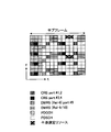
- CSI-RS is a single resource block specified by LTE, and is a control signal such as PDCCH (Physical Downlink Control Channel), user data such as PDSCH (Physical Downlink Shared Channel), CRS (Cell-specific Reference Signal), DM- Assigned so as not to overlap with other reference signals such as RS (Demodulation-Reference Signal).
- One resource block includes 12 subcarriers continuous in the frequency direction and 14 symbols continuous in the time axis direction. From the viewpoint of suppressing PAPR, two resource elements adjacent to each other in the time axis direction are assigned as a set to resources to which CSI-RS can be assigned.
- CSI-RS which is a user-specific reference signal
- CSI-RS from a plurality of transmission points can be separated at the user terminal, so CSI-RS based interference measurement is promising.
- CSI-RS defined in LTE Rel. 10 LTE
- LTE Long Term Evolution
- the present applicant has added zero power CSI-RS (hereinafter referred to as interference measurement zero power CSI-RS) used only for interference measurement, and zero power for interference measurement between transmission points. It was proposed to shift in the frequency axis direction so that CSI-RS resources do not overlap. Thereby, the interference signal can be estimated for CSI (Channel State Information) calculation to the user terminal using the resource element (RE) in which the downlink shared data channel (PDSCH) is not transmitted. In this case, a different interference measurement zero power CSI-RS pattern is assigned to each transmission point or each of a plurality of transmission points.
- CSI-RS Channel State Information
- interference measurement can be performed using both non-zero power CSI-RS (existing CSI-RS with transmission power) and zero power CSI-RS for interference measurement, and the number of CSI-RS available for interference measurement can be increased. Interference measurement accuracy can be improved.
- the transmission power of the interference measurement zero power CSI-RS is 0, the signal component received by the resource to which the interference measurement zero power CSI-RS is assigned can be handled as the interference component as it is. Can reduce the processing burden.
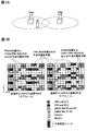
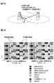
- FIG. 2A shows a case where transmission is performed from the transmission points TP # 1 and TP # 2 to the user terminal UE.
- FIG. 2B shows an example of a CSI-RS pattern in which zero power CSI-RS for interference measurement is arranged.
- the left subframe is a subframe transmitted from TP # 1
- the right subframe is a subframe transmitted from TP # 2.
- the first and seventh REs in the frequency direction and the tenth and eleventh REs in the time direction are used for interference measurement.
- the zero power CSI-RS is arranged, PDSCH is not transmitted by the RE of TP # 1 and TP # 2 (zero power). Therefore, with these REs, it is possible to estimate interference signals of cells outside TP # 1 and TP # 2.
- the zero power CSI ⁇ for interference measurement is supplied to the third and ninth REs in the frequency direction and the tenth and eleventh REs in the time direction, respectively.
- RS When RS is arranged, PDSCH is not transmitted by the RE of TP # 1 (zero power). Therefore, in these REs, it is possible to estimate interference signals of cells outside TP # 1 (cells other than TP # 2 + TP # 1, TP # 2). Also, as shown in FIG. 2B, in the subframe of TP # 2, the zero power CSI ⁇ for interference measurement is supplied to the fifth and eleventh REs in the frequency direction and the tenth and eleventh REs in the time direction, respectively. When RS is arranged, PDSCH is not transmitted by the RE of TP # 2 (zero power). Therefore, in these REs, it is possible to estimate interference signals of cells outside TP # 2 (cells other than TP # 1 + TP # 1, TP # 2).
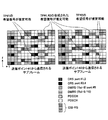
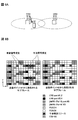
- FIG. 3 shows a case where transmission is performed from the transmission points TP # 1 and TP # 2 to the user terminal UE.
- FIG. 3 shows an example of a CSI-RS pattern in which CSI-RSs are arranged.
- the left subframe is a subframe transmitted from TP # 1
- the right subframe is a subframe transmitted from TP # 2.
- the CSI-RS is assigned to the second and eighth REs in the frequency direction and the tenth and eleventh REs in the time direction, respectively.
- these REs enable estimation of a desired signal composed of TP # 1 and TP # 2.
- CSI-RSs are arranged in the fourth and tenth REs in the frequency direction and in the tenth and eleventh REs in the time direction in the TP # 1 subframe, respectively. This RE enables estimation of a desired signal of TP # 1. Also, as shown in FIG.
- the essence of the present invention is to determine resource information of resources for allocating reference signals for estimating desired signals and resources for estimating interference signals in each base station apparatus, and notifying resource information to the user terminal,
- the notified resource information is received, the desired signal estimation and the interference signal estimation are performed based on the resource information, and the channel state is measured using the estimation result of the estimation unit.
- Channel quality information optimum for the transmission form is fed back from the user terminal. Thereby, throughput is improved and a highly efficient wireless communication system can be realized.
- Downlink CoMP transmission includes Coordinated Scheduling / Coordinated Beamforming and Joint processing.
- Coordinated Scheduling / Coordinated Beamforming is a method for transmitting a shared data channel from only one cell to one user terminal UE, and in the frequency / space domain considering interference from other cells and interference to other cells. Assign radio resources.
- Joint processing is a method for transmitting a shared data channel from a plurality of cells at the same time by applying precoding, and a joint transmission for transmitting a shared data channel from a plurality of cells to one user terminal UE, and an instantaneous process.
- DPS Dynamic Point Selection
- DBS Dynamic Point Blanking
- the optimum desired signal estimation method and interference signal estimation method are selected in accordance with transmission modes from a plurality of transmission points.
- a shared data channel signal is transmitted from a plurality of cells (TP # 1 (connected cell), TP # 2 (cooperative cell)) to one user terminal UE. .
- TP # 1 connected cell
- TP # 2 cooperative cell
- interference signals it is desirable to estimate interference signals of cells (transmission points) other than TP # 1 and TP # 2.
- the interference signal estimation is the first and seventh RE in the frequency direction and the tenth in the time direction in each subframe of TP # 1 and TP # 2.
- the interference measurement zero power CSI-RS is arranged in the 11th RE (the interference measurement zero power CSI-RS is arranged in the same RE in the connection cell (transmission point) and the cooperative cell (transmission point)), and TP Interference signals of cells other than # 1 and TP # 2 are estimated.
- the CSI ⁇ is assigned to the second and eighth REs in the frequency direction and the tenth and eleventh REs in the time direction in each subframe of TP # 1 and TP # 2.
- An RS is arranged (CSI-RS is arranged in the same RE in the connected cell (transmission point) and the cooperative cell (transmission point)), and a desired signal combined with TP # 1 and TP # 2 is estimated.
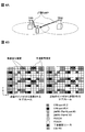
- FIG. 5A In dynamic point blanking type CoMP transmission, data transmission in a certain area is stopped with respect to a transmission point (TP # 2 (cooperative cell (transmission point)) in FIG. 5A) that causes interference. For this reason, as for the desired signal, it is desirable to estimate the desired signal of TP # 1 (connected cell (transmission point)). As for interference signals, it is desirable to estimate interference signals of cells other than TP # 1 and TP # 2. For this reason, as shown in FIG. 5B, the interference signal estimation is the first and seventh REs in the frequency direction and the tenth in the time direction in each subframe of TP # 1 and TP # 2.
- the interference measurement zero power CSI-RS is arranged in the 11th RE (the interference measurement zero power CSI-RS is arranged in the same RE in the connection cell (transmission point) and the cooperative cell (transmission point)), and TP Interference signals of cells other than # 1 and TP # 2 are estimated.
- CSI-RSs are arranged in the fourth and tenth REs in the frequency direction and in the tenth and eleventh REs in the time direction in the subframe of TP # 1, respectively (connection CSI-RS is arranged in RE of the cell (transmission point)) and a desired signal of TP # 1 is estimated.
- FIG. 6A shows single-cell transmission transmitted from one transmission point TP # 1 to the user terminal.
- the desired signal it is desirable to estimate the desired signal of TP # 1 (connected cell (transmission point)).
- the interference signal it is desirable to estimate an interference signal of a cell other than TP # 1. Therefore, as shown in FIG. 6B, the interference signal is estimated to be the third and ninth REs in the frequency direction and the tenth and eleventh REs in the time direction in the subframe of TP # 1, respectively.
- interference measurement zero power CSI-RS is arranged (interference measurement zero power CSI-RS is arranged in RE of the connected cell (transmission point)), and interference signals of cells other than TP # 1 are estimated.
- CSI-RSs are arranged in the fourth and tenth REs in the frequency direction and in the tenth and eleventh REs in the time direction in the subframe of TP # 1, respectively (connection CSI-RS is arranged in RE of the cell (transmission point)) and a desired signal of TP # 1 is estimated.
- an optimum method for measuring a desired signal-to-interference signal (a method for measuring a desired signal-to-interference signal used for CSI measurement) is selected according to the transmission mode.
- CQI quality information
- the radio base station signals information on the desired signal estimation method and the interference signal estimation method to the user terminal. That is, RE (Signal Measurement Resource: SMR) information used for desired signal estimation, RE (Interference Measurement Resource: IMR) information used for interference signal estimation, combination information of SMR and IMR (one or more of these information) Is used as resource information for resources to allocate reference signals for estimating desired signals and resources for estimating interference signals), the radio base station signals to the user terminal.
- RE Signaling
- IMR Interference Measurement Resource
- combination information of SMR and IMR one or more of these information
- Is used as resource information for resources to allocate reference signals for estimating desired signals and resources for estimating interference signals
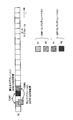
- Such information may be notified from the radio base station to the user terminal by higher layer signaling (RRC signaling), or may be notified dynamically from the radio base station to the user terminal by downlink control information (DCI). For example, as shown in FIG.
- RRC signaling higher layer signaling
- DCI downlink control information
- the radio base station when it is desired to feed back CSI, the radio base station sends a user terminal to the user terminal as shown in FIG. Is estimated using the first and seventh REs in the frequency direction and the tenth and eleventh REs in the time direction in the subframes of TP # 1 and TP # 2, respectively.
- the radio base station applies a semi-standard to the user terminal so that the fourth and tenth REs in the frequency direction and the tenth and eleventh REs in the time direction are used. Signal statically or dynamically.
- one or a plurality of SMRs and one or a plurality of IMRs are arranged (configured) in the same or different subframes. For example, as shown in FIG.
- SMR # 1 and IMR # 2 there are two types of SMR and IMR (SMR # 1, SMR # 2, IMR # 1, IMR # 2), and SMR # 1 and SMR # 2 exist in the same subframe
- signaling (CSI # 1) indicating that CSI is obtained by a combination of SMR # 1 and IMR # 1, and a combination of SMR # 2 and IMR # 2
- CSI # 2 By notifying the user terminal of signaling (CSI # 2) indicating that CSI is to be obtained, the two types of CSI (CSI # 1, CSI # 2) can be fed back to the user terminal. It becomes possible.
- SMR # 1 SMR # 2
- IMR # 1 IMR # 2
- CSI # 2 signaling
- CSI # 2 indicating that CSI is obtained by a combination of IMR # 2
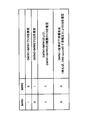
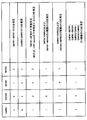
- signaling can be performed with 2 bits as shown in FIG.
- FIG. 8 when CSI is estimated by SMR # 1 + IMR # 1, bit “10” is set, and when CSI is estimated by SMR # 2 + IMR # 2, bit “01” is set, and SMR # 1 + IMR # 1 and SMR # 1 + IMR are set.
- Bit “11” is used when two types of CSI of # 2 are estimated, and bit “00” is used when CSI is estimated using SMR # 1 and a conventional interference estimation method (for example, interference estimation using CRS). .
- a conventional interference estimation method for example, interference estimation using CRS.
- signaling can be performed with 4 bits as shown in FIG. .
- FIG. 9 when CSI is estimated by SMR # 1 + IMR # 1, bit “1010” is set, and when CSI is estimated by SMR # 2 + IMR # 2, bit “0101” is set, and SMR # 1 and the conventional interference estimation method are used.
- estimating CSI by for example, interference estimation using CRS
- when estimating two types of CSI of SMR # 1 + IMR # 1 and SMR # 1 + IMR # 2 it is set to bit “1011”.
- desired signal estimation and interference signal estimation are performed using the RE specified from the notified SMR information, IMR information, SMR and IMR combination information, and one or a plurality of CSIs are calculated using the estimation result.
- Ask. The user terminal feeds back one or a plurality of CSIs thus determined to the radio base station.
- the subframe for obtaining the interference signal may be limited by the bitmap information notified from the radio base station through higher layer signaling (for example, RRC signaling).
- the user terminal obtains CSI using signaling of a combination of SMR and IMR and signaling that limits a subframe for obtaining an interference signal.
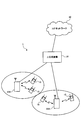
- FIG. 10 is an explanatory diagram of the system configuration of the wireless communication system according to the present embodiment.
- the radio communication system shown in FIG. 10 is a system that includes, for example, the LTE system or SUPER 3G.
- carrier aggregation in which a plurality of fundamental frequency blocks with the system band of the LTE system as a unit is integrated is used.
- this wireless communication system may be called IMT-Advanced or 4G.
- the wireless communication system 1 is configured to include base station apparatuses 20A and 20B at each transmission point, and user terminals 10 that communicate with the base station apparatuses 20A and 20B.
- the base station devices 20 ⁇ / b> A and 20 ⁇ / b> B are connected to the higher station device 30, and the higher station device 30 is connected to the core network 40.
- the base station devices 20A and 20B are connected to each other by wired connection or wireless connection.
- the user terminal 10 can communicate with the base station apparatuses 20A and 20B that are transmission points.
- the upper station device 30 includes, for example, an access gateway device, a radio network controller (RNC), a mobility management entity (MME), and the like, but is not limited thereto.
- RNC radio network controller
- MME mobility management entity
- the user terminal 10 includes an existing terminal (Rel.10LTE) and a support terminal (for example, Rel.11LTE).
- a support terminal for example, Rel.11LTE.
- the user terminal 10 will be described as a user terminal unless otherwise specified. For convenience of explanation, it is assumed that the user terminal 10 performs wireless communication with the base station apparatuses 20A and 20B.
- OFDMA Orthogonal Frequency Division Multiple Access
- SC-FDMA Single Carrier-Frequency Division Multiple Access
- the wireless access method is not limited to this.
- OFDMA is a multi-carrier transmission scheme that performs communication by dividing a frequency band into a plurality of narrow frequency bands (subcarriers) and mapping data to each subcarrier.
- SC-FDMA is a single carrier transmission method that reduces interference between terminals by dividing a system band into bands each consisting of one or continuous resource blocks for each terminal, and a plurality of terminals using different bands. .
- the downlink communication channel includes a PDSCH (Physical Downlink Shared Channel) as a downlink data channel shared by the user terminal 10 and a downlink L1 / L2 control channel (PDCCH, PCFICH, PHICH). Transmission data and higher control information are transmitted by the PDSCH.
- PDSCH and PUSCH scheduling information is transmitted by PDCCH (Physical Downlink Control Channel).
- the number of OFDM symbols used for PDCCH is transmitted by PCFICH (Physical Control Format Indicator Channel).
- HARQ ACK / NACK for PUSCH is transmitted by PHICH (Physical Hybrid-ARQ Indicator Channel).
- the uplink communication channel has PUSCH (Physical Uplink Shared Channel) as an uplink data channel shared by each user terminal and PUCCH (Physical Uplink Control Channel) as an uplink control channel. Transmission data and higher control information are transmitted by this PUSCH. Also, downlink channel state information (CSI (including CQI and the like)), ACK / NACK, and the like are transmitted by PUCCH.
- PUSCH Physical Uplink Shared Channel
- PUCCH Physical Uplink Control Channel
- Transmission data and higher control information are transmitted by this PUSCH.
- CSI including CQI and the like
- ACK / NACK are transmitted by PUCCH.
- the base station apparatus 20 includes a transmission / reception antenna 201, an amplifier unit 202, a transmission / reception unit (notification unit) 203, a baseband signal processing unit 204, a call processing unit 205, and a transmission path interface 206.
- Transmission data transmitted from the base station apparatus 20 to the user terminal via the downlink is input from the higher station apparatus 30 to the baseband signal processing unit 204 via the transmission path interface 206.
- the downlink data channel signal is transmitted from the RCP layer, such as PDCP layer processing, transmission data division / combination, RLC (Radio Link Control) retransmission control transmission processing, and MAC (Medium Access).
- RCP layer such as PDCP layer processing, transmission data division / combination, RLC (Radio Link Control) retransmission control transmission processing, and MAC (Medium Access).
- Control Retransmission control, for example, HARQ transmission processing, scheduling, transmission format selection, channel coding, inverse fast Fourier transform (IFFT) processing, and precoding processing are performed.
- transmission processing such as channel coding and inverse fast Fourier transform is performed on the signal of the physical downlink control channel, which is the downlink control channel.
- the baseband signal processing unit 204 notifies the control information for each user terminal 10 to wirelessly communicate with the base station apparatus 20 to the user terminals 10 connected to the same transmission point through the broadcast channel.
- Information for communication at the transmission point includes, for example, system bandwidth in the uplink or downlink, and root sequence identification information for generating a random access preamble signal in PRACH (Physical Random Access Channel) (Root Sequence Index) etc. are included.
- the transmission / reception unit 203 converts the baseband signal output from the baseband signal processing unit 204 into a radio frequency band.
- the amplifier unit 202 amplifies the radio frequency signal subjected to frequency conversion and outputs the amplified signal to the transmission / reception antenna 201.
- a radio frequency signal received by the transmission / reception antenna 201 is amplified by the amplifier unit 202 and frequency-converted by the transmission / reception unit 203 to be a baseband signal. And is input to the baseband signal processing unit 204.
- the baseband signal processing unit 204 performs FFT processing, IDFT processing, error correction decoding, MAC retransmission control reception processing, RLC layer, PDCP layer reception processing on transmission data included in the baseband signal received in the uplink I do.
- the decoded signal is transferred to the higher station apparatus 30 via the transmission path interface 206.
- the call processing unit 205 performs call processing such as communication channel setting and release, state management of the base station apparatus 20, and management of radio resources.
- the user terminal 10 includes a transmission / reception antenna 101, an amplifier unit 102, a transmission / reception unit (reception unit) 103, a baseband signal processing unit 104, and an application unit 105.
- a radio frequency signal received by the transmission / reception antenna 101 is amplified by the amplifier unit 102, frequency-converted by the transmission / reception unit 103, and converted into a baseband signal.
- the baseband signal is subjected to FFT processing, error correction decoding, retransmission control reception processing, and the like by the baseband signal processing unit 104.
- downlink transmission data is transferred to the application unit 105.
- the application unit 105 performs processing related to layers higher than the physical layer and the MAC layer. Also, the broadcast information in the downlink data is also transferred to the application unit 105.
- uplink transmission data is input from the application unit 105 to the baseband signal processing unit 104.
- the baseband signal processing unit 104 performs mapping processing, retransmission control (HARQ) transmission processing, channel coding, DFT processing, and IFFT processing.
- the transmission / reception unit 103 converts the baseband signal output from the baseband signal processing unit 104 into a radio frequency band. Thereafter, the amplifier unit 102 amplifies the frequency-converted radio frequency signal and transmits it from the transmission / reception antenna 101.
- HARQ retransmission control
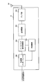
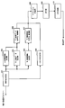
- each functional block in FIG. 13 mainly relates to the baseband processing unit shown in FIG. Further, the functional block diagram of FIG. 13 is simplified for explaining the present invention, and is assumed to have a configuration normally provided in the baseband processing unit.
- the base station apparatus 20 includes a measurement RE determination unit 401, a higher control information generation unit 402, a downlink transmission data generation unit 403, a downlink control information generation unit 404, a CSI-RS generation unit 405, and a downlink transmission.
- a data encoding / modulating unit 406 and a downlink control information encoding / modulating unit 407 are provided.
- the base station apparatus 20 includes a downlink channel multiplexing unit 408, an IFFT unit 409, and a CP adding unit 410.
- the measurement RE determining unit 401 determines a resource (measurement RE) to which a reference signal (CSI-RS) for estimating a desired signal is allocated and a resource (measurement RE) for estimating an interference signal. Further, the measurement RE determining unit 401 determines a combination of a resource (measurement RE) to which a reference signal for estimating a desired signal is allocated and a resource (measurement RE) for estimating an interference signal. These resources (measurement REs) are resource information.
- the measurement RE determining unit 401 determines the resource information according to the transmission form of a plurality of base station apparatuses (transmission points). For example, when the transmission form is Joint transmission type cooperative multipoint transmission, the measurement RE determining unit 401, as shown in FIG. 4B, for the desired signal, the connection transmission point (TP # 1) and the cooperative transmission point (TP The resource is determined so as to estimate the combined desired signal of # 2) (in FIG. 4B, in the subframes of TP # 1 and TP # 2, they are the second and eighth REs in the frequency direction, respectively). The 10th and 11th REs in the time direction) and the interference signal are measured so that interference signals of transmission points other than the connection transmission point (TP # 1) and the coordinated transmission point (TP # 2) are estimated. (RE) in FIG. 4B, in the subframes of TP # 1 and TP # 2, respectively, the first and seventh in the frequency direction 10th time direction a RE and 11 th RE).
- the measurement RE determining unit 401 estimates the desired signal of the connection transmission point (TP # 1) for the desired signal as shown in FIG. 5B. (In FIG. 5B, in the TP # 1 subframe, the fourth and tenth REs in the frequency direction and the tenth and eleventh REs in the time direction, respectively) Determines a resource (measurement RE) so as to estimate interference signals of transmission points other than the connection transmission point (TP # 1) and the coordinated transmission point (TP # 2) (in FIG. 5B, TP # 1, TP # 2 in each subframe, the first and seventh REs in the frequency direction and the tenth and eleventh REs in the time direction).
- the measurement RE determining unit 401 allocates resources so as to estimate the desired signal of the connection transmission point (TP # 1) for the desired signal, as shown in FIG. 6B.
- the resource (measurement RE) is determined so as to estimate the interference signal of the transmission point other than (TP # 1) (in FIG. 6B, the third and ninth REs in the frequency direction in the subframe of TP # 1, respectively. And the 10th and 11th REs in the time direction).
- this resource information is sent to the higher control information generation unit 402 for higher layer signaling (for example, RRC signaling). Further, this resource information is sent to the downlink control information generation unit 404 to be included in the downlink control information when dynamically signaling to the user terminal. Further, this resource information is sent to the CSI-RS generator 405 to generate CSI-RS, and in order to make downlink transmission data zero power (muting) (zero power CSI-RS for interference measurement is arranged) Is transmitted to the downlink transmission data generation unit 403.
- muting zero power CSI-RS for interference measurement is arranged
- the higher control information generating section 402 generates higher control information transmitted / received by higher layer signaling (for example, RRC signaling), and outputs the generated higher control information to the downlink transmission data encoding / modulating section 406.
- the higher control information generation unit 402 generates higher control information including the resource information output from the measurement RE determination unit 401.
- the higher-level control information generation unit 402 sets information on a combination of a resource (measurement RE) to which a reference signal (CSI-RS) for estimating a desired signal is allocated and a resource (measurement RE) for estimating an interference signal as shown in FIG. Bit information as shown in FIG. 9 is generated.
- Downlink transmission data generation section 403 generates downlink transmission data and outputs the downlink transmission data to downlink transmission data encoding / modulation section 406.
- the downlink transmission data generation section 403 arranges (mutes) the interference measurement zero power CSI-RS according to the resource information output from the measurement RE determination section 401.
- the downlink control information generation unit 404 generates downlink control information, and outputs the downlink control information to the downlink control information encoding / modulation unit 407.
- the downlink control information generation unit 404 generates downlink control information including resource information when dynamically signaling resource information to the user terminal.
- Downlink transmission data coding / modulation section 406 performs channel coding and data modulation on the downlink transmission data and higher control information, and outputs the result to downlink channel multiplexing section 408.
- the downlink control information coding / modulation section 407 performs channel coding and data modulation on the downlink control information and outputs the result to the downlink channel multiplexing section 408.
- the CSI-RS generation unit 405 generates a CSI-RS according to the resource information output from the measurement RE determination unit 401, and outputs the CSI-RS to the downlink channel multiplexing unit 408.
- the downlink channel multiplexing unit 408 combines the downlink control information, CSI-RS, higher control information, and downlink transmission data to generate a transmission signal.
- the downlink channel multiplexing unit 408 outputs the generated transmission signal to the IFFT unit 409.
- the IFFT unit 409 performs an inverse fast Fourier transform on the transmission signal, and converts the frequency domain signal into a time domain signal.
- the transmission signal after IFFT is output to CP adding section 410.
- CP adding section 410 adds a CP (Cyclic Prefix) to the transmission signal after IFFT, and outputs the transmission signal after CP addition to amplifier section 202 shown in FIG.
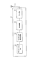
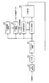
- each functional block in FIG. 14 mainly relates to the baseband processing unit 104 shown in FIG. Further, the functional blocks shown in FIG. 12 are simplified for the purpose of explaining the present invention, and the configuration normally provided in the baseband processing unit is provided.
- the user terminal 10 includes a CP removing unit 301, an FFT unit 302, a downlink channel separating unit 303, a downlink control information receiving unit 304, a downlink transmission data receiving unit 305, an interference signal estimating unit 306, A channel estimation unit 307 and a CQI measurement unit 308 are provided.
- the transmission signal transmitted from the base station apparatus 20 is received by the transmission / reception antenna 101 shown in FIG.
- CP removing section 301 removes the CP from the received signal and outputs it to FFT section 302.
- the FFT unit 302 performs fast Fourier transform (FFT) on the signal after CP removal, and converts the signal in the time domain into a signal in the frequency domain.
- FFT section 302 outputs the signal converted into the frequency domain signal to downlink channel separation section 303.
- the downlink channel separation unit 303 separates the downlink channel signal into downlink control information, downlink transmission data, and CSI-RS.
- the downlink channel separation unit 303 outputs downlink control information to the downlink control information reception unit 304, outputs downlink transmission data and higher-level control information to the downlink transmission data reception unit 305, and outputs CSI-RS to the channel estimation unit 307. .
- the downlink control information reception unit 304 demodulates the downlink control information, and outputs the demodulated downlink control information to the downlink transmission data reception unit 305.
- the downlink transmission data reception unit 305 demodulates downlink transmission data using the demodulated downlink control information.
- the downlink transmission data reception section 305 identifies the desired signal measurement RE (CSI-RS resource) and the interference signal measurement RE based on the resource information included in the higher control information.
- Downlink transmission data receiving section 305 demodulates user data except for desired signal measurement RE (CSI-RS resource) and interference signal measurement RE. Also, downlink transmission data reception section 305 outputs higher control information included in the downlink transmission data to interference signal estimation section 306.
- the interference signal estimation unit 306 estimates the interference signal by the interference signal measurement RE based on the resource information included in the upper control information (or downlink control information).
- the interference signal estimation unit 306 has 1 in the frequency direction in each subframe of TP # 1 and TP # 2, as shown in FIG. 4B.
- the interference signal is estimated with the tenth and eleventh REs in the time direction of the seventh and seventh REs.
- the interference signal estimation unit 306 performs frequency in each subframe of TP # 1 and TP # 2, as shown in FIG. 5B.
- the interference signal is estimated with the first and seventh REs in the direction and the tenth and eleventh REs in the time direction.
- the interference signal estimation unit 306 is the third and ninth REs in the frequency direction in the subframe of TP # 1, respectively, as shown in FIG. 6B.
- the interference signal is estimated at the 10th and 11th REs in the time direction.
- the interference signal estimation unit 306 estimates the interference signal in this way, and averages the measurement results in all resource blocks.
- the CQI measurement unit 308 is notified of the averaged interference signal estimation result.
- the channel estimation unit 307 identifies a desired signal measurement RE (CSI-RS resource) based on resource information included in the upper control information (or downlink control information), and uses the desired signal measurement RE (CSI-RS resource) for the desired signal. Is estimated.
- CSI-RS resource a desired signal measurement RE (CSI-RS resource) based on resource information included in the upper control information (or downlink control information)
- CSI-RS resource uses the desired signal measurement RE (CSI-RS resource) for the desired signal. Is estimated.
- the channel estimation unit 307 is second in the frequency direction in each subframe of TP # 1 and TP # 2, as shown in FIG. 4B. And the 8th RE, and the 10th and 11th REs in the time direction are used to estimate the desired signal. Further, for example, when the transmission form is Dynamic Point Blanking-type cooperative multipoint transmission, the channel estimation unit 307 is fourth and tenth in the frequency direction in the subframe of TP # 1, respectively, as shown in FIG. 5B. The desired signal is estimated with the 10th and 11th REs in the time direction.
- the channel estimation unit 307 is the fourth and tenth REs in the frequency direction in the subframe of TP # 1, respectively, as shown in FIG. 6B.
- the desired signal is estimated at the 10th and 11th REs in the time direction.
- the channel estimation unit 307 notifies the CQI measurement unit 308 of the channel estimation value.
- the CQI measurement unit 308 calculates a channel state (CQI) based on the interference estimation result notified from the interference signal estimation unit 306, the channel estimation result notified from the channel estimation unit 307, and the feedback mode. Note that any of Wideband CQI, Subband CQI, and best-M average may be set as the feedback mode.
- the CQI calculated by the CQI measurement unit 308 is notified to the base station apparatus 20 as feedback information.
- the CSI-RS pattern shown in FIG. 1 to FIG. 6 follows the CSI-RS pattern defined in LTE-A (Rel. 10 LTE) as it is (can be referred to as reuse). Therefore, a resource to be muted can be signaled to the existing terminal (Rel. 10 LTE) within the range of terminal capability (function supported by the terminal).
- the present invention is not limited to the above embodiment, and can be implemented with various modifications.
- the setting position of CSI-RS, the setting position of muting (zero power), the number of processing units, the processing procedure, the number of CSI-RSs, the number of mutings in the above description The number of transmission points can be changed as appropriate.
- the transmission points may be antennas. Other modifications can be made without departing from the scope of the present invention.
Abstract
Description
下りリンクの通信チャネルは、ユーザ端末10で共有される下りデータチャネルとしてのPDSCH(Physical Downlink Shared Channel)と、下りL1/L2制御チャネル(PDCCH、PCFICH、PHICH)とを有する。PDSCHにより、送信データ及び上位制御情報が伝送される。PDCCH(Physical Downlink Control Channel)により、PDSCHおよびPUSCHのスケジューリング情報などが伝送される。PCFICH(Physical Control Format Indicator Channel)により、PDCCHに用いるOFDMシンボル数が伝送される。PHICH(Physical Hybrid-ARQ Indicator Channel)により、PUSCHに対するHARQのACK/NACKが伝送される。 Here, the communication channel will be described.
The downlink communication channel includes a PDSCH (Physical Downlink Shared Channel) as a downlink data channel shared by the
Claims (11)
- チャネル状態測定用の参照信号を送信する複数の基地局装置と、前記複数の基地局装置のいずれかに接続するユーザ端末とを備えた無線通信システムであって、
前記各基地局装置は、
希望信号推定のための前記参照信号を割り当てるリソース及び干渉信号推定のためのリソースのリソース情報を決定する決定部と、
前記リソース情報を前記ユーザ端末に通知する通知部とを備え、
前記ユーザ端末は、
通知されたリソース情報を受信する受信部と、
前記リソース情報に基づいて、希望信号推定及び干渉信号推定する推定部と、
前記推定部の推定結果を用いてチャネル状態を測定する測定部とを備えたことを特徴とする無線通信システム。 A wireless communication system comprising a plurality of base station devices that transmit reference signals for channel state measurement, and a user terminal connected to any of the plurality of base station devices,
Each of the base station devices
A determination unit for determining resource information for allocating the reference signal for estimating a desired signal and resource for estimating an interference signal;
A notification unit for notifying the resource information to the user terminal,
The user terminal is
A receiving unit for receiving the notified resource information;
An estimation unit for estimating a desired signal and an interference signal based on the resource information;
A wireless communication system, comprising: a measurement unit that measures a channel state using an estimation result of the estimation unit. - 前記リソース情報は、前記希望信号推定のための前記参照信号を割り当てるリソース及び前記干渉信号推定のためのリソースの組合せの情報であることを特徴とする請求項1記載の無線通信システム。 The wireless communication system according to claim 1, wherein the resource information is information of a combination of a resource to which the reference signal for estimating the desired signal is allocated and a resource for estimating the interference signal.
- 前記決定部は、前記複数の基地局装置の送信形態に応じてリソース情報を決定することを特徴とする請求項1又は請求項2記載の無線通信システム。 The wireless communication system according to claim 1 or 2, wherein the determination unit determines resource information according to a transmission form of the plurality of base station apparatuses.
- 前記送信形態が協調マルチポイント送信又はシングルセル送信であることを特徴とする請求項3記載の無線通信システム。 The wireless communication system according to claim 3, wherein the transmission form is cooperative multipoint transmission or single cell transmission.
- 前記決定部は、前記送信形態がJoint transmission型協調マルチポイント送信である場合に、前記希望信号については、接続送信ポイント及び協調送信ポイントの合成された希望信号を推定するようにリソースを決定し、前記干渉信号については、前記接続送信ポイント及び協調送信ポイント以外の送信ポイントの干渉信号を推定するようにリソースを決定することを特徴とする請求項4記載の無線通信システム。 The determining unit determines a resource so as to estimate a combined desired signal of a connection transmission point and a cooperative transmission point for the desired signal when the transmission form is Joint transmission type cooperative multipoint transmission; 5. The radio communication system according to claim 4, wherein for the interference signal, a resource is determined so as to estimate an interference signal of a transmission point other than the connection transmission point and the cooperative transmission point.
- 前記決定部は、前記送信形態がDynamic Point Blanking型協調マルチポイント送信である場合に、前記希望信号については、接続送信ポイントの希望信号を推定するようにリソースを決定し、前記干渉信号については、接続送信ポイント及び協調送信ポイント以外の送信ポイントの干渉信号を推定するようにリソースを決定することを特徴とする請求項4記載の無線通信システム。 The determination unit determines a resource so as to estimate a desired signal of a connection transmission point for the desired signal when the transmission form is Dynamic Point Blanking type cooperative multipoint transmission, and for the interference signal, 5. The wireless communication system according to claim 4, wherein the resource is determined so as to estimate an interference signal of a transmission point other than the connection transmission point and the cooperative transmission point.
- 前記決定部は、前記送信形態がシングルセル送信である場合に、前記希望信号については、接続送信ポイントの希望信号を推定するようにリソースを決定し、前記干渉信号については、接続送信ポイント以外の送信ポイントの干渉信号を推定するようにリソースを決定することを特徴とする請求項4記載の無線通信システム。 The determination unit determines a resource so as to estimate a desired signal of a connection transmission point for the desired signal when the transmission form is single cell transmission, and the interference signal other than the connection transmission point for the interference signal. 5. The wireless communication system according to claim 4, wherein the resource is determined so as to estimate an interference signal at a transmission point.
- 前記通知部は、前記リソース情報を示すビット情報を準静的に又は動的にシグナリングすることを特徴とする請求項1から請求項7のいずれかに記載の無線通信システム。 The wireless communication system according to any one of claims 1 to 7, wherein the notification unit signals the bit information indicating the resource information semi-statically or dynamically.
- チャネル状態測定用の参照信号を送信する複数の基地局装置と、前記複数の基地局装置のいずれかに接続するユーザ端末とを備えた無線通信システムの基地局装置であって、
希望信号推定のための前記参照信号を割り当てるリソース及び干渉信号推定のためのリソースのリソース情報を決定する決定部と、
前記リソース情報を前記ユーザ端末に通知する通知部とを備えたことを特徴とする基地局装置。 A base station apparatus of a radio communication system comprising a plurality of base station apparatuses that transmit a reference signal for channel state measurement and a user terminal connected to any of the plurality of base station apparatuses,
A determination unit for determining resource information for allocating the reference signal for estimating a desired signal and resource for estimating an interference signal;
A base station apparatus comprising: a notification unit that notifies the user terminal of the resource information. - チャネル状態測定用の参照信号を送信する複数の基地局装置と、前記複数の基地局装置のいずれかに接続するユーザ端末とを備えた無線通信システムのユーザ端末であって、
前記基地局装置から通知された、希望信号推定のための前記参照信号を割り当てるリソース及び干渉信号推定のためのリソースのリソース情報を受信する受信部と、
前記リソース情報に基づいて、希望信号推定及び干渉信号推定する推定部と、
前記推定部の推定結果を用いてチャネル状態を測定する測定部とを備えたことを特徴とするユーザ端末。 A user terminal of a wireless communication system comprising a plurality of base station devices that transmit reference signals for channel state measurement, and a user terminal connected to any of the plurality of base station devices,
A receiving unit that receives resource information of a resource for allocating the reference signal for estimating a desired signal and a resource for estimating an interference signal notified from the base station apparatus;
An estimation unit for estimating a desired signal and an interference signal based on the resource information;
A user terminal comprising: a measurement unit that measures a channel state using an estimation result of the estimation unit. - チャネル状態測定用の参照信号を送信する複数の基地局装置と、前記複数の基地局装置のいずれかに接続するユーザ端末とを備えた無線通信システムにおけるチャネル状態情報測定方法であって、
前記各基地局装置において、希望信号推定のための前記参照信号を割り当てるリソース及び干渉信号推定のためのリソースのリソース情報を決定する工程と、
前記リソース情報を前記ユーザ端末に通知する工程と、
前記ユーザ端末において、通知されたリソース情報を受信する工程と、
前記リソース情報に基づいて、希望信号推定及び干渉信号推定する工程と、
前記推定部の推定結果を用いてチャネル状態を測定する工程とを備えたことを特徴とするチャネル状態情報測定方法。 A channel state information measurement method in a wireless communication system comprising a plurality of base station devices that transmit a channel state measurement reference signal and a user terminal connected to any of the plurality of base station devices,
In each of the base station devices, determining resource information of a resource for allocating the reference signal for estimating a desired signal and a resource for estimating an interference signal;
Notifying the resource information to the user terminal;
In the user terminal, receiving the notified resource information;
A step of estimating a desired signal and an interference signal based on the resource information;
A channel state information measuring method comprising: measuring a channel state using an estimation result of the estimation unit.
Priority Applications (7)
| Application Number | Priority Date | Filing Date | Title |
|---|---|---|---|
| US14/375,151 US10057040B2 (en) | 2012-01-30 | 2013-01-30 | Wireless communication system, base station apparatus, user terminal, and channel state information measurement method |
| CN201380007298.2A CN104509189B (en) | 2012-01-30 | 2013-01-30 | Wireless communication system, base station apparatus, user terminal and channel state information measuring method |
| ES13743296T ES2763543T3 (en) | 2012-01-30 | 2013-01-30 | Wireless communication system, base station device, user terminal and channel status information measurement method |
| CA2862094A CA2862094A1 (en) | 2012-01-30 | 2013-01-30 | Wireless communication system, base station apparatus, user terminal, and channel state information measurement method |
| KR1020147020170A KR20140130667A (en) | 2012-01-30 | 2013-01-30 | Wireless communication system, base station device, user terminal, and channel-state information measurement method |
| EP13743296.9A EP2811798B1 (en) | 2012-01-30 | 2013-01-30 | Wireless communication system, base station device, user terminal, and channel-state information measurement method |
| RU2014132831A RU2613338C2 (en) | 2012-01-30 | 2013-01-30 | Wireless communication system, base station, user terminal and method for determining channel state |
Applications Claiming Priority (2)
| Application Number | Priority Date | Filing Date | Title |
|---|---|---|---|
| JP2012-017278 | 2012-01-30 | ||
| JP2012017278A JP5526165B2 (en) | 2012-01-30 | 2012-01-30 | Wireless communication system, base station apparatus, user terminal, and channel state information measuring method |
Publications (1)
| Publication Number | Publication Date |
|---|---|
| WO2013115258A1 true WO2013115258A1 (en) | 2013-08-08 |
Family
ID=48905290
Family Applications (1)
| Application Number | Title | Priority Date | Filing Date |
|---|---|---|---|
| PCT/JP2013/052062 WO2013115258A1 (en) | 2012-01-30 | 2013-01-30 | Wireless communication system, base station device, user terminal, and channel-state information measurement method |
Country Status (10)
| Country | Link |
|---|---|
| US (1) | US10057040B2 (en) |
| EP (1) | EP2811798B1 (en) |
| JP (1) | JP5526165B2 (en) |
| KR (1) | KR20140130667A (en) |
| CN (1) | CN104509189B (en) |
| CA (1) | CA2862094A1 (en) |
| ES (1) | ES2763543T3 (en) |
| PT (1) | PT2811798T (en) |
| RU (1) | RU2613338C2 (en) |
| WO (1) | WO2013115258A1 (en) |
Cited By (3)
| Publication number | Priority date | Publication date | Assignee | Title |
|---|---|---|---|---|
| JP2016529808A (en) * | 2013-08-09 | 2016-09-23 | 富士通株式会社 | Information exchange method, base station, and communication system |
| CN113875281A (en) * | 2019-03-29 | 2021-12-31 | 株式会社Ntt都科摩 | User terminal and wireless communication method |
| CN114041301A (en) * | 2019-05-02 | 2022-02-11 | 株式会社Ntt都科摩 | User terminal and wireless communication method |
Families Citing this family (13)
| Publication number | Priority date | Publication date | Assignee | Title |
|---|---|---|---|---|
| KR102190628B1 (en) | 2012-03-19 | 2020-12-14 | 텔레폰악티에볼라겟엘엠에릭슨(펍) | Configuration of coordinated multipoint transmission hypotheses for channel state information reporting |
| US9723506B2 (en) * | 2012-04-13 | 2017-08-01 | Lg Electronics Inc. | Method and apparatus for reporting channel state information in wireless communication system |
| KR101526163B1 (en) * | 2012-09-07 | 2015-06-05 | 주식회사 케이티 | Method for Transmitting and Receiving Configuration Information of Interference Measurement Resource, Method for Measuring Interference Measurement Resource, Terminal and Transmission Point thereof |
| US9629013B2 (en) * | 2013-07-18 | 2017-04-18 | Marvell World Trade Ltd. | Channel quality indication with filtered interference |
| US10034283B2 (en) * | 2013-08-23 | 2018-07-24 | Qualcomm Incorporated | CSI and ACK reporting enhancements in LTE/LTE-A with unlicensed spectrum |
| US10958391B2 (en) * | 2014-11-18 | 2021-03-23 | Qualcomm Incorporated | Tone plans for wireless communication networks |
| WO2017197148A1 (en) * | 2016-05-11 | 2017-11-16 | Docomo Innovations, Inc. | Method for wireless communication, user equipment, and base station |
| CN107733549B (en) * | 2016-08-10 | 2020-09-25 | 华为技术有限公司 | Channel quality information calculation method, device and system |
| US11172390B2 (en) * | 2016-12-20 | 2021-11-09 | Sharp Kabushiki Kaisha | Base station apparatus, terminal apparatus, communication method, and integrated circuit |
| EP3639392A1 (en) * | 2017-06-14 | 2020-04-22 | SONY Corporation | Operating a terminal device and a base station in a wireless mimo system |
| RU2680825C1 (en) * | 2018-06-14 | 2019-02-27 | Общество с ограниченной ответственностью "КАСКАД" | Method of automatic input in communication and selection of optimal mode of work of the subscriber and basic data transfer stations |
| US20220038194A1 (en) * | 2018-11-02 | 2022-02-03 | Ntt Docomo, Inc. | User terminal and radio communication method |
| CN113747491A (en) * | 2021-08-26 | 2021-12-03 | 上海擎昆信息科技有限公司 | Interference reporting method and user equipment |
Citations (1)
| Publication number | Priority date | Publication date | Assignee | Title |
|---|---|---|---|---|
| WO2011118141A1 (en) * | 2010-03-26 | 2011-09-29 | パナソニック株式会社 | Wireless reception device, wireless transmission device, and wireless communication method |
Family Cites Families (6)
| Publication number | Priority date | Publication date | Assignee | Title |
|---|---|---|---|---|
| JP4711750B2 (en) * | 2005-04-13 | 2011-06-29 | 株式会社エヌ・ティ・ティ・ドコモ | Mobile communication system, mobile station, base station, and communication control method |
| CN103039107B (en) | 2010-03-29 | 2016-01-27 | Lg电子株式会社 | For the method and apparatus of the measurement to the Inter-Cell Interference Coordination in radio communications system |
| CN101867457B (en) * | 2010-06-21 | 2016-01-20 | 中兴通讯股份有限公司 | The processing method of channel condition information and subscriber equipment |
| JP5373706B2 (en) * | 2010-06-21 | 2013-12-18 | 株式会社エヌ・ティ・ティ・ドコモ | Base station apparatus, mobile terminal apparatus and communication control method |
| CN101924610B (en) * | 2010-08-02 | 2012-12-26 | 西安电子科技大学 | Method for designing and distributing channel state information reference signal (CSI-RS) in LTE-A (Long Term Evolution-Advanced) system |
| GB2496205A (en) * | 2011-11-07 | 2013-05-08 | Renesas Mobile Corp | Applying a biasing parameter associated with a transmission scheme to a channel quality parameter |
-
2012
- 2012-01-30 JP JP2012017278A patent/JP5526165B2/en active Active
-
2013
- 2013-01-30 PT PT137432969T patent/PT2811798T/en unknown
- 2013-01-30 RU RU2014132831A patent/RU2613338C2/en active
- 2013-01-30 ES ES13743296T patent/ES2763543T3/en active Active
- 2013-01-30 CA CA2862094A patent/CA2862094A1/en not_active Abandoned
- 2013-01-30 KR KR1020147020170A patent/KR20140130667A/en not_active Application Discontinuation
- 2013-01-30 CN CN201380007298.2A patent/CN104509189B/en active Active
- 2013-01-30 EP EP13743296.9A patent/EP2811798B1/en active Active
- 2013-01-30 WO PCT/JP2013/052062 patent/WO2013115258A1/en active Application Filing
- 2013-01-30 US US14/375,151 patent/US10057040B2/en active Active
Patent Citations (1)
| Publication number | Priority date | Publication date | Assignee | Title |
|---|---|---|---|---|
| WO2011118141A1 (en) * | 2010-03-26 | 2011-09-29 | パナソニック株式会社 | Wireless reception device, wireless transmission device, and wireless communication method |
Non-Patent Citations (4)
| Title |
|---|
| "Feasibility Study for Evolved UTRA and UTRAN", 3GPP, TR25.912 (V7.1.0, September 2006 (2006-09-01) |
| SAMSUNG: "Discussion on the Definition of CQI in CoMP", 3GPP TSG RAN WG1 #67, 18 November 2011 (2011-11-18), XP050562326, Retrieved from the Internet <URL:http://www.3gpp.org/ftp/tsg_ran/WG1_RL1/TSGR1_67/Docs/R1-114225.zip> [retrieved on 20130218] * |
| SAMSUNG: "Interference measurement for downlink CoMP", 3GPP TSG RAN WG1 #66BIS MEETING, 14 October 2011 (2011-10-14), XP050538235, Retrieved from the Internet <URL:http://www.3gpp.org/ftp/tsg_ran/WG1_RL1/TSGR1_66b/Docs/R1-113091.zip> [retrieved on 20130218] * |
| See also references of EP2811798A4 |
Cited By (5)
| Publication number | Priority date | Publication date | Assignee | Title |
|---|---|---|---|---|
| JP2016529808A (en) * | 2013-08-09 | 2016-09-23 | 富士通株式会社 | Information exchange method, base station, and communication system |
| CN113875281A (en) * | 2019-03-29 | 2021-12-31 | 株式会社Ntt都科摩 | User terminal and wireless communication method |
| CN113875281B (en) * | 2019-03-29 | 2024-01-02 | 株式会社Ntt都科摩 | User terminal and wireless communication method |
| CN114041301A (en) * | 2019-05-02 | 2022-02-11 | 株式会社Ntt都科摩 | User terminal and wireless communication method |
| CN114041301B (en) * | 2019-05-02 | 2023-11-14 | 株式会社Ntt都科摩 | Terminal, wireless communication method and system |
Also Published As
| Publication number | Publication date |
|---|---|
| RU2613338C2 (en) | 2017-03-16 |
| EP2811798A4 (en) | 2015-09-16 |
| US10057040B2 (en) | 2018-08-21 |
| PT2811798T (en) | 2020-01-13 |
| US20140369224A1 (en) | 2014-12-18 |
| CN104509189A (en) | 2015-04-08 |
| RU2014132831A (en) | 2016-03-27 |
| EP2811798B1 (en) | 2019-12-04 |
| CA2862094A1 (en) | 2013-08-08 |
| JP5526165B2 (en) | 2014-06-18 |
| CN104509189B (en) | 2019-10-01 |
| EP2811798A1 (en) | 2014-12-10 |
| JP2013157816A (en) | 2013-08-15 |
| ES2763543T3 (en) | 2020-05-29 |
| KR20140130667A (en) | 2014-11-11 |
Similar Documents
| Publication | Publication Date | Title |
|---|---|---|
| JP5526165B2 (en) | Wireless communication system, base station apparatus, user terminal, and channel state information measuring method | |
| US9716540B2 (en) | User terminal, radio communication system, radio communication method and radio base station | |
| US9634808B2 (en) | Radio communication system, radio communication method, user terminal and radio base station | |
| US9124320B2 (en) | Mobile terminal apparatus, radio base station apparatus and radio communication method | |
| JP5918680B2 (en) | Wireless communication system, base station apparatus, user terminal, and wireless communication method | |
| JP6096119B2 (en) | Radio communication system, radio base station apparatus, user terminal, and radio communication method | |
| WO2013168542A1 (en) | Wireless communication system, base station device, user terminal, and wireless communication method | |
| WO2013051510A1 (en) | Wireless communications system, feedback method, user terminal, and wireless base station device | |
| WO2013161588A1 (en) | Wireless communications system, base station device, user terminal, and wireless communications method | |
| WO2013141338A1 (en) | Wireless communication system, user terminal, wireless base station device and wireless communication method | |
| US9312984B2 (en) | Radio communication system, radio base station apparatus, user terminal and radio communication method | |
| WO2013069665A1 (en) | Wireless communication system, interferometry method, wireless base station device, and user terminal | |
| WO2013069536A1 (en) | Wireless communication system, wireless base station, user equipment, and wireless communication method | |
| WO2013137218A1 (en) | Wireless base station, user terminal, wireless communication method, and wireless communication system | |
| WO2016190215A1 (en) | User terminal, wireless base station, and wireless communication method | |
| JP6027325B2 (en) | Radio communication system, user terminal, radio base station apparatus, and radio communication method | |
| JP2016029861A (en) | User terminal, radio communication system, and radio communication method |
Legal Events
| Date | Code | Title | Description |
|---|---|---|---|
| 121 | Ep: the epo has been informed by wipo that ep was designated in this application |
Ref document number: 13743296 Country of ref document: EP Kind code of ref document: A1 |
|
| ENP | Entry into the national phase |
Ref document number: 20147020170 Country of ref document: KR Kind code of ref document: A |
|
| ENP | Entry into the national phase |
Ref document number: 2862094 Country of ref document: CA |
|
| WWE | Wipo information: entry into national phase |
Ref document number: 14375151 Country of ref document: US |
|
| NENP | Non-entry into the national phase |
Ref country code: DE |
|
| WWE | Wipo information: entry into national phase |
Ref document number: 2013743296 Country of ref document: EP |
|
| WWE | Wipo information: entry into national phase |
Ref document number: 2014132831 Country of ref document: RU |