WO2011040067A1 - Liquid vaporization system - Google Patents
Liquid vaporization system Download PDFInfo
- Publication number
- WO2011040067A1 WO2011040067A1 PCT/JP2010/055652 JP2010055652W WO2011040067A1 WO 2011040067 A1 WO2011040067 A1 WO 2011040067A1 JP 2010055652 W JP2010055652 W JP 2010055652W WO 2011040067 A1 WO2011040067 A1 WO 2011040067A1
- Authority
- WO
- WIPO (PCT)
- Prior art keywords
- liquid
- liquid material
- vaporizer
- vaporization system
- diaphragm
- Prior art date
Links
Images


Classifications
-
- B—PERFORMING OPERATIONS; TRANSPORTING
- B01—PHYSICAL OR CHEMICAL PROCESSES OR APPARATUS IN GENERAL
- B01D—SEPARATION
- B01D1/00—Evaporating
- B01D1/22—Evaporating by bringing a thin layer of the liquid into contact with a heated surface
- B01D1/221—Composite plate evaporators
-
- B—PERFORMING OPERATIONS; TRANSPORTING
- B01—PHYSICAL OR CHEMICAL PROCESSES OR APPARATUS IN GENERAL
- B01B—BOILING; BOILING APPARATUS ; EVAPORATION; EVAPORATION APPARATUS
- B01B1/00—Boiling; Boiling apparatus for physical or chemical purposes ; Evaporation in general
- B01B1/005—Evaporation for physical or chemical purposes; Evaporation apparatus therefor, e.g. evaporation of liquids for gas phase reactions
-
- B—PERFORMING OPERATIONS; TRANSPORTING
- B01—PHYSICAL OR CHEMICAL PROCESSES OR APPARATUS IN GENERAL
- B01J—CHEMICAL OR PHYSICAL PROCESSES, e.g. CATALYSIS OR COLLOID CHEMISTRY; THEIR RELEVANT APPARATUS
- B01J7/00—Apparatus for generating gases
-
- H—ELECTRICITY
- H01—ELECTRIC ELEMENTS
- H01L—SEMICONDUCTOR DEVICES NOT COVERED BY CLASS H10
- H01L21/00—Processes or apparatus adapted for the manufacture or treatment of semiconductor or solid state devices or of parts thereof
- H01L21/02—Manufacture or treatment of semiconductor devices or of parts thereof
- H01L21/027—Making masks on semiconductor bodies for further photolithographic processing not provided for in group H01L21/18 or H01L21/34
- H01L21/0271—Making masks on semiconductor bodies for further photolithographic processing not provided for in group H01L21/18 or H01L21/34 comprising organic layers
- H01L21/0273—Making masks on semiconductor bodies for further photolithographic processing not provided for in group H01L21/18 or H01L21/34 comprising organic layers characterised by the treatment of photoresist layers
Definitions
- the present invention relates to a liquid vaporization system.
- a liquid material for changing a hydrophilic surface to hydrophobic is vaporized by a vaporizer, and the vaporized liquid material is used. Wafer surface treatment is performed.
- this kind of vaporizer what vaporizes the said liquid material is used, for example by heating a liquid material with a heater.
- the liquid material vaporized by the vaporizer is usually supplied to the wafer accommodated in the chamber by the carrier gas.
- an air-fuel mixture of the vaporized liquid material and the carrier gas is supplied to the wafer.
- the concentration of the liquid material in the air-fuel mixture fluctuates during processing, the processing uniformity is impaired. Can occur. Therefore, in order to perform a stable surface treatment, it is necessary to keep the concentration of the liquid material in the air-fuel mixture constant during the treatment.
- Patent Document 1 discloses that a porous body is formed in a vaporizer by filling the vaporizer with a granular material, and a liquid material is heated outside the porous body.
- the structure which provides the heater for doing is disclosed.
- the liquid material can enter the gap between the porous bodies, and the liquid material that has entered the gap can be vaporized by being heated through the porous body by the heater.
- the contact area between the porous body and the liquid material can be increased, the vaporization of the liquid material can be promoted, and as a result, the concentration of the liquid material in the air-fuel mixture during processing can be kept constant. I can expect.
- the carrier gas may reach the inside of the porous body depending on the structure of the porous body such as a porous body having a fine gap. The case where it cannot enter is assumed. In this case, since the liquid material vaporized inside the porous body cannot be sent out to the chamber side by the carrier gas, it may remain inside the porous body.
- the present invention has been made in view of the above circumstances, and has as its main object to provide a liquid vaporization system capable of promoting the vaporization of the liquid material while solving the problem of the remaining liquid material. It is.
- a liquid vaporization system is a liquid vaporization system including a vaporizer that heats and vaporizes a liquid material, and the vaporizer is formed to be substantially flat and the liquid material is A liquid adhesion surface to be adhered, a thinning means for thinning the liquid material adhering to the liquid adhesion surface, and a heating means for heating the liquid adhesion surface are provided.
- the liquid material adhering to the liquid adhering surface can be thinned (thinly spread) by the thinning means.
- the liquid material made into the thin film can be heated by heating a liquid adhesion surface with a heating means.
- the liquid material can be heated by increasing the contact area (that is, the heat transfer area) between the liquid material and the liquid adhesion surface, vaporization of the liquid material can be promoted.
- the contact area that is, the heat transfer area
- the liquid adhesion surface for heating the liquid material is formed substantially flat, the vaporized liquid material is left on the downstream side (for example, the chamber) by the carrier gas without remaining on the liquid adhesion surface (and thus in the vaporizer). ). Therefore, the evaporation of the liquid material can be promoted while solving the problem of the remaining liquid material.
- this liquid vaporization system can be used, for example in the manufacture of a semiconductor device, when surface treatment is performed using a liquid material obtained by vaporizing an object to be processed such as a wafer.
- a chamber in which an object to be processed such as a wafer is accommodated is connected to the downstream side of the vaporizer, and the liquid material vaporized by the vaporizer is supplied to the object to be processed in the chamber.
- a system for surface treatment is conceivable.
- coated with respect to a to-be-processed object, such as a hydrophobization process liquid can be considered, for example.
- the thinning means is a wetting promoting means for promoting the wetting of the liquid material with respect to the liquid adhering surface, and the wetting accelerating means is performed on the liquid adhering surface.
- the liquid material adhering to the liquid adhering surface is thinned by promoting the wetting of the liquid material.
- the liquid material adhering to the liquid adhering surface can be thinned by promoting the wetting of the liquid material to the liquid adhering surface.
- a driving device for example, a pressure device for compressing the liquid material
- the liquid vaporization system according to a third aspect is characterized in that, in the second aspect, the wetting accelerating means is a fine concavo-convex portion provided on the liquid adhesion surface in order to improve the wettability with respect to the liquid material.
- the fine irregularities provided on the liquid adhesion surface can be improved. Thereby, the wetting of the liquid material with respect to the liquid adhesion surface can be promoted.
- a mesh formed in a flat plate shape as a whole by placing a wire material in a mesh shape is placed (overlaid) on the liquid adhesion surface.
- grooved part is provided by making into a recessed part the part enclosed by the said wire with the said wire as a convex part, It is characterized by the above-mentioned.
- the concavo-convex portion can be formed only by overlapping the flat mesh on the liquid adhesion surface, the effect of the third invention can be obtained with a simple configuration.
- the mesh is formed of a metal (for example, stainless steel) wire, the mesh can be heated by the heating means through the liquid adhesion surface. Can also be heated. Thereby, vaporization of the liquid material can be further promoted.
- the mesh is configured to be removable from the liquid adhesion surface, it can be replaced with a mesh having an appropriate roughness (mesh fineness) according to the wettability of the liquid material to be vaporized. Therefore, it is convenient when vaporizing a plurality of types of liquid materials having different wettability.
- the liquid adhesion surface is provided with a supply port for supplying the liquid material between the liquid adhesion surface and the mesh.
- the supply port formed in the liquid adhesion surface is formed between the liquid adhesion surface and the mesh, the supplied liquid material is interposed between the mesh and the liquid adhesion surface by interfacial tension. It can flow through the gap. As a result, the liquid material can be smoothly supplied to a large area of the mesh without causing the liquid material to scatter (spray).
- the supply port is not necessarily a single one, and a plurality of supply ports may be formed.
- a liquid vaporization system is characterized in that, in the fifth aspect of the invention, the liquid vaporization system further comprises a positioning member that determines a relative positional relationship between the liquid adhesion surface and the mesh in the stacking direction.
- the mesh gap is filled, for example, when the mesh is attached to the liquid adhesion surface with an adhesive or the like, or when the fastening portion is fastened with a fastening member. It is possible to avoid the problem that the liquid material aggregates in the vicinity and a solid matter may be generated.
- the positioning member may be pressed against the liquid adhesion surface with a net or a string fixed to the end of the liquid adhesion surface.
- the positioning member may be configured to partially insert a spacer for forming a gap between the liquid adhesion surface and the mesh.
- the positioning member presses the mesh against the liquid adhesion surface at a plurality of positions where the positioning member is arranged at a predetermined interval.
- a pressing member is provided.
- the interfacial tension in the gap between the mesh and the liquid adhesion surface at the predetermined interval It is possible to realize a gap flow that is a flow utilizing the above with a simple configuration. Since the gap flow is formed between a plurality of pressing positions, it is possible to provide a degree of freedom in design such as the roughness of the mesh and the positional relationship between the plurality of pressing positions. Thereby, the design tool for implement
- the pressing member may be configured as a plurality of members arranged at a plurality of positions where the mesh is pressed, or may include a common member having a plurality of convex portions for pressing.
- the liquid adhesion surface is formed as a surface of a heating plate heated by the heating means
- the heating plate is formed with an orifice that connects a back surface opening formed on the back surface that is the surface opposite to the liquid adhesion surface, and the supply port, Comprising a shut-off valve for opening and closing the back opening,
- the back surface opening is formed at a position facing the supply port across the orifice.
- the liquid material can be blocked in the vicinity of the liquid adhesion surface. Therefore, the fluctuation
- a recess is formed on the back surface of the heating plate,
- the back opening is formed in the recess,
- the shut-off valve includes a valve body that closes the back surface opening.
- the back surface opening includes a valve seat formed in a recess formed on the back surface of the heating plate, and the valve seat is closed by the valve body, so regardless of the thickness of the heating plate.
- the length of the flow path between the supply port and the back surface opening can be shortened. Furthermore, the length of the flow path can be freely set by adjusting the depth of the recess.
- the valve body in the ninth aspect, includes a sealing portion that is an annular protrusion that surrounds the back surface opening in a state where the back surface opening is closed.
- the sealing performance can be improved while suppressing the retention of bubbles due to the rise of the valve seat.
- the liquid vaporization system of an eleventh invention is characterized in that, in the ninth invention, the back opening has a valve seat formed in the recess.
- the liquid vaporization system according to a twelfth aspect of the present invention is characterized in that, in the ninth aspect, the back surface opening has a flat surface facing the valve body in an annular region surrounding the back surface opening.
- the valve seat and the protrusion are not provided to increase the surface pressure, but a flat surface facing the valve body may be provided. This is because no back pressure is applied at the time of interruption in the present invention.
- the liquid vaporization system according to a thirteenth aspect of the present invention is characterized in that, in the ninth to twelfth aspects, the valve body has a diaphragm for opening and closing the back surface opening.
- the diaphragm since the diaphragm does not have a sliding part on the flow path side, it is possible to prevent the liquid material from being generated due to the accumulation of the liquid material in the sliding part. Thereby, generation
- the liquid adhesion surface is formed as a surface of a heating plate heated by the heating means,
- the heating plate is provided with a temperature sensor for measuring the temperature of the liquid adhesion surface.
- the vaporization state on the liquid adhesion surface can be observed as a temperature change of the heating plate due to the heat of vaporization.
- This temperature sensor can be used for various purposes such as monitoring of the vaporization process and failure detection.
- a liquid vaporization system includes the pump for supplying the liquid material to the vaporizer according to the first to fourteenth aspects of the invention.
- the pump includes a first diaphragm driving unit, a second diaphragm driving unit, and a coupling unit that couples the first diaphragm driving unit and the second diaphragm driving unit in a direction facing each other.
- the connecting portion has a pump chamber to which a suction passage for sucking the liquid material and a discharge passage for discharging the liquid material are connected.
- the first diaphragm driving unit has a first diaphragm constituting a part of the pump chamber
- the second diaphragm driving unit has a second diaphragm constituting a part of the pump chamber,
- the first diaphragm and the second diaphragm form surfaces facing each other in the pump chamber
- the first diaphragm driving unit includes a first displacement limiting unit that limits a first displacement amount by which the first diaphragm can be mechanically displaced, and the first displacement amount is adjustable.
- the second diaphragm driving unit includes a second displacement limiting unit that limits a second displacement amount by which the second diaphragm can be mechanically displaced and can adjust the second displacement amount. It is characterized by.
- the amount of displacement that the first diaphragm and the second diaphragm can be mechanically displaced can be limited so as to be adjustable. Therefore, the number of operations per unit time is performed by performing the full operation of the limitation. By operating the, the supply speed of the liquid material can be controlled easily and accurately.
- the present invention also has an advantage that a sensor for measuring the displacement amount of the diaphragm can be omitted.
- the first displacement limiting portion performs a first rotation that is a rotation with respect to the pump, with a displacement direction of the first diaphragm as an axis.
- the first displacement amount can be adjusted by
- the second displacement limiting unit can adjust the second displacement amount by performing a second rotation which is a rotation with respect to the pump, with a displacement direction of the second diaphragm as an axis.
- the pump is provided with a measurement unit that indicates a value related to a discharge amount measured in accordance with the first rotation angle and the second rotation angle.
- the value related to the discharge amount has a broad meaning including the value related to the discharge amount, such as the feed amount of the first displacement limiting unit and the second displacement limiting unit caused by the first rotation and the second rotation, for example. is doing.
- the concavo-convex portion includes a plurality of concave portions and a plurality of convex portions, the concave portions and the convex portions. Are alternately arranged along two different directions parallel to the liquid adhesion surface.
- the wettability that is, the wettability of the liquid adhesion surface with respect to the liquid material is improved. Can be increased in the direction. That is, since wetting of the liquid material with respect to the liquid adhesion surface can be promoted in the two directions, the contact area between the liquid material and the liquid adhesion surface can be further increased. Thereby, vaporization of the liquid material can be further promoted.
- the liquid vaporization system according to an eighteenth aspect of the present invention is the liquid vaporization system according to the second aspect, wherein the vaporizer includes a pair of the liquid adhesion surfaces, and the liquid adhesion surfaces are arranged to face each other with a predetermined gap therebetween.
- the promoting means promotes the wetting of the liquid material in the gap with respect to each liquid adhesion surface by capillary action.
- the liquid material having a contact angle with the liquid adhesion surface of less than 90 ° that is, easily wetted with the liquid adhesion surface
- the liquid is placed in the gap between the opposed liquid adhesion surfaces.
- the liquid material can be attached in a thin film form to each liquid adhesion surface by capillary action (in other words, using surface tension).
- vaporization of the liquid material can be further promoted by heating the pair of liquid attachment surfaces by the heating means.
- the liquid vaporization system according to any one of the first to eighteenth aspects of the present invention, a pump that supplies the liquid material to the vaporizer through a supply passage, And a supply amount adjusting means for adjusting the supply amount.
- the supply amount of the liquid material supplied to the vaporizer by the pump can be adjusted by the supply amount adjusting means. Therefore, for example, in a system for supplying the liquid material vaporized by the vaporizer to the chamber in which the wafer is accommodated, the liquid material vaporized in the vaporizer is adjusted by adjusting the supply amount of the liquid material to the vaporizer by the pump.
- the amount of supply to the chamber can be adjusted. That is, in this case, when supplying a predetermined amount of vaporized liquid material to the chamber, it is only necessary to supply the predetermined amount of liquid material from the liquid tank in which the liquid material is stored to the vaporizer by a pump.
- the liquid material in the liquid tank can be stored fresh without being vaporized.
- an on-off valve for opening and closing the supply passage may be provided in the middle of the supply passage, and when the liquid material is not supplied to the vaporizer by the pump, the on-off valve may be closed.
- the liquid vaporization system according to a twentieth aspect of the present invention is the liquid vaporization system according to the nineteenth aspect, wherein the pump supplies the liquid material to the vaporizer through the supply passage and then sucks the liquid material remaining in the supply passage. It is characterized by comprising a suck back control means.
- the present invention even when a part of the liquid material remains in the supply passage after the liquid material is supplied to the vaporizer through the supply passage by the pump, the remaining liquid material is sucked by the pump ( That is, it can be sucked back). As a result, the liquid material remaining in the supply passage (for example, the passage end on the vaporizer side) is vaporized, thereby avoiding the disadvantage that the amount of vaporization of the liquid material varies.
- a liquid vaporization system is characterized in that, in the nineteenth or twentieth aspect, the liquid vaporization apparatus is unitized including the pump, the vaporizer, and the supply passage.
- the liquid vaporizer is unitized including the pump and the vaporizer. Therefore, for example, in a system for supplying a liquid material vaporized by a vaporizer to a chamber in which a wafer is accommodated, the same apparatus provided on the upstream side of the chamber can be configured compactly. It becomes possible to arrange in. In this case, the length of the pipe connecting the liquid vaporizer (vaporizer) and the chamber can be made relatively short, so that the liquid material vaporized in the vaporizer is recycled in the pipe before being supplied to the chamber. Liquefaction can be suppressed.
- (A) is a side view of a liquid vaporizer
- (b) is a longitudinal cross-sectional view which shows the structure of a liquid vaporizer.
- the perspective view which shows the structure of a vaporizer
- the top view which expands and shows the mesh on a thermal storage board.
- the top view which shows the structure of the liquid vaporization apparatus 120 of 2nd Embodiment.
- Sectional drawing which shows the cross section of a vaporizer
- the perspective view which shows the thermal storage board of a vaporizer
- the internal structure figure which looked at the inside of a vaporizer from the lower part (gravity standard in an equipped state).
- the bottom view which shows the state which looked at the heater of the vaporizer from the downward direction.
- the bottom view which shows the state which looked at the back cover of the vaporizer from the downward direction.
- Sectional drawing which shows the cross section of a vaporizer
- the expanded sectional view which shows the state which the shut-off valve closed the orifice.
- the expanded sectional view which shows the state which the cutoff valve opened the orifice.
- the graph which shows the relationship between the open / close state of a shut-off valve, and the measured temperature by a thermocouple.
- the longitudinal cross-sectional view which shows the structure of the vaporizer
- the expanded sectional view which shows the state which the shut-off valve in another example closed the orifice.
- the expanded sectional view which shows the state which the shut-off valve in another example closed the orifice.
- a liquid vaporization system is used to vaporize the hydrophobization treatment liquid as the liquid material.
- the vaporized liquid material is applied to the surface of a semiconductor wafer (hereinafter referred to as a wafer for short) to improve the adhesion of the resist solution to the wafer.
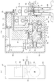
- the liquid vaporization system 10 is provided with a liquid vaporization apparatus 20 for vaporizing a liquid material.
- the liquid vaporizer 20 includes a pump 11, a vaporizer 12, a suction side valve 13, and a discharge side valve 14.
- the pump 11 sucks and discharges the liquid material, and is constituted by a diaphragm pump.
- the pump 11 is connected to an electropneumatic regulator 34 that adjusts the pressure of the air supplied to the pump 11, and the liquid material is sucked and discharged by adjusting the air pressure by the electropneumatic regulator 34.
- the pump 11 sucks the liquid material stored in the liquid tank X through the suction passage 15 and supplies (discharges) the sucked liquid material to the vaporizer 12 through the discharge passage 16.
- the suction passage 15 is provided with a suction side valve 13 that permits or prohibits the flow of the liquid material
- the discharge passage 16 is also provided with a discharge side valve 14 that permits or prohibits the flow of the liquid material. These valves 13 and 14 are opened and closed by electrical operation.
- the vaporizer 12 vaporizes a liquid material and includes a heater 22 and the like which will be described later.
- the liquid material supplied to the vaporizer 12 by the pump 11 is vaporized in the vaporizer 12.
- a gas introduction pipe 28 and a gas discharge pipe 29 are connected to the vaporizer 12.
- Nitrogen gas as a carrier gas is supplied to the vaporizer 12 from a nitrogen gas source through the gas introduction pipe 28, and the supplied nitrogen gas is mixed with the liquid material vaporized in the vaporizer 12. Then, the mixed gas mixture is discharged from the vaporizer 12 through the gas discharge pipe 29.
- the liquid vaporization system 10 includes a chamber 18 that accommodates the wafer 30.
- the chamber 18 is connected to the vaporizer 12 via a gas discharge pipe 29, and the air-fuel mixture discharged from the vaporizer 12 is supplied to the chamber 18 via the gas discharge pipe 29.
- the downstream end (chamber 18 side) end of the gas discharge pipe 29 is a discharge nozzle 29a, and the air-fuel mixture is discharged toward the wafer 30 from the discharge nozzle 29a.
- the chamber 18 is connected to an exhaust duct 19 for discharging the air-fuel mixture in the chamber 18.
- the used air-fuel mixture in the chamber 18 is sucked out by an exhaust blower or the like and is discharged to the outside through the exhaust duct 19.
- the liquid vaporization system 10 further includes a controller 40 as control means.
- the controller 40 controls the suction and discharge operation of the pump 11 by driving and controlling the electropneumatic regulator 34 and also controls the operation of the valves 13 and 14. The details of the electrical configuration of the system 10 centering on the controller 40 will be described later.
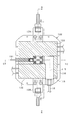
- FIG. 2A is a side view of the liquid vaporizer 20
- FIG. 2B is a longitudinal sectional view showing the configuration of the liquid vaporizer 20.
- the liquid vaporizer 20 includes a body 31, a cylinder body 32, and a cover 33.
- These members 31 to 33 are arranged in the above order in a substantially horizontal direction (left and right in FIG. 2B). In a state of being overlapped in the direction), they are integrally assembled by a fastening member such as a bolt.
- the body 31 is made of, for example, a fluorine resin
- the cylinder body 32 and the cover 33 are made of, for example, polypropylene resin.
- the body 31, the cylinder body 32, and the cover 33 have a hollow portion extending in the stacking direction, and a valve member 47 is provided in the hollow portion so as to be able to reciprocate.
- the body 31 is formed with a substantially cylindrical cylindrical recess 35 that opens to the cylinder body 32 side, and two passages 16 and 37 that communicate with the cylindrical recess 35. Of these two passages 16, 37, one passage 37 leads to the suction port 36 for sucking the liquid material, and the other passage 16 leads to the vaporizer 12.
- a suction pipe (not shown) leading to the liquid tank X is connected to the suction port 36, and the suction pipe 15 and the passage 37 constitute the suction passage 15 in FIG.
- the suction side valve 13 and the discharge side valve 14 are provided side by side with their positions slightly shifted up and down.
- the suction side valve 13 includes a valve body 38 that opens and closes the suction passage 37, and permits or prohibits the flow of the liquid material by moving the valve body 38 in the opening and closing direction.
- the discharge side valve 14 includes a valve body 39 that opens and closes the discharge passage 16, and permits or prohibits the flow of the liquid material by moving the valve body 39 in the opening and closing direction.
- the vaporizer space S is an installation space for installing the vaporizer 12.
- the cylinder body 32 is formed with a substantially disk-shaped disk recess 41 that opens to the body 31 side.
- the disk concave portion 41 forms a continuous cylindrical space together with the cylindrical concave portion 35 of the body 31.
- the cylinder body 32 is formed with a substantially cylindrical cylinder portion 42 that opens to the cover 33 side, and a valve support hole 43 that allows the cylinder portion 42 to communicate with the disc recess 41.
- the valve support hole 43 is formed coaxially with the cylinder portion 42 (center position is the same) and with a diameter smaller than the cylinder diameter.
- a guide 45 having a valve support hole 45a is assembled to the cover 33.
- the valve support hole 45a is a through hole coaxial with the valve support hole 43 of the cylinder body 32 described above.
- the valve member 47 is configured by integrating a rod 48 and a diaphragm valve body 49, and the diaphragm valve body 49 is connected to one end of the rod 48.
- the rod 48 is formed with a substantially disc-shaped piston portion 51 having the same outer diameter as the inner diameter of the cylinder portion 42.
- the outer peripheral part of the piston part 51 is in contact with the inner surface of the cylinder part 42 and is slidably accommodated in the cylinder part 42.
- the rod 48 is inserted into a valve support hole 45 a of a guide 45 provided in the cover 33 and is inserted into a valve support hole 43 provided in the cylinder body 32.
- the cylinder part 42 of the cylinder body 32 is divided into two spaces by the piston part 51 of the rod 48.
- the space closer to the body 31 than the piston portion 51 is a pressure control chamber 54.
- Operation air is introduced into the pressure control chamber 54 from the outside through an air introduction passage 32 a formed in the cylinder body 32, thereby adjusting the air pressure in the pressure control chamber 54.
- the space closer to the cover 33 than the piston portion 51 is a spring chamber 55, and a spiral coil-shaped spring 56 is disposed in the spring chamber 55. Therefore, the air pressure in the pressure control chamber 54 and the urging force of the spring 56 act on the rod 48 in a direction opposite to each other, and the position of the rod 48 is adjusted by the balance of these forces.
- the diaphragm valve body 49 is connected to the end portion of the rod 48 on the body 31 side, and is formed of, for example, a fluororesin.
- the diaphragm valve body 49 divides a continuous space between an outer edge portion 49a sandwiched between the body 31 and the cylinder body 32, and the cylindrical recess portion 35 of the body 31 and the disk recess portion 41 of the cylinder body 32 into two spaces. And a diaphragm film 49b. Of the two divided spaces, the space closer to the body 31 than the diaphragm membrane 49 b is a pump chamber 58, and the suction passage 37 and the discharge passage 16 described above communicate with the pump chamber 58.
- the diaphragm membrane 49b of the diaphragm valve body 49 is displaced in the same direction, and as a result, the volume of the pump chamber 58 changes in size.
- the liquid material can be sucked into the pump chamber 58 through the suction passage 37 and the liquid material in the pump chamber 58 can be discharged through the discharge passage 16. That is, in the liquid vaporizer 20, the diaphragm pump 11 is configured in this way.
- a position detector 61 for detecting the amount of movement of the valve member 47 is provided above the body 31 and the cylinder body 32.
- the position detector 61 includes a case 62 fixed to the upper surface of the cylinder body 32 and a position sensor 63 accommodated in the case 62.
- the position sensor 63 includes a sensor main body 63a and a movable rod 63b that can move in a protruding direction or an immersion direction with respect to the sensor main body 63a.
- the movable rod 63b is urged in a direction protruding from the sensor main body 63a by an urging means (spring or the like) (not shown), and the position in the axial direction is changed by pressing the tip portion.
- the configuration relating to the detection of the movement amount of the valve member 47 is such that the end of the valve member 47 opposite to the diaphragm valve body 49 protrudes from the cover 33, and an arm 66 is connected to the protruding portion by a screw 65. .
- the arm 66 is provided so as to extend in a direction orthogonal to the axial direction of the valve member 47, and a position adjusting screw 67 is provided at a tip portion opposite to the connection side with the valve member 47.
- the tip of the position adjusting screw 67 and the movable rod 63b of the position sensor 63 are in contact with each other.
- the arm 66 moves in the same direction, and the position of the movable rod 63b in the axial direction changes. Be changed. Thereby, the movement amount of the valve member 47 can be detected by the position sensor 63.
- An air passage 62 a is formed in the case 62, and the air passage 62 a communicates with the air introduction passage 32 a of the cylinder body 32.
- Operation air is supplied to the air passage 62a from an external device (for example, an electropneumatic regulator) (not shown), and the operation air is supplied to the pressure control chamber 54 through the air passage 62a and the air introduction passage 32a.
- an external device for example, an electropneumatic regulator
- the volume of the pump chamber 58 is controlled by controlling the amount of movement of the valve member 47, and as a result, the suction and discharge of the liquid material by the pump 11 is controlled.
- the present apparatus 20 is provided with covers 68 and 69 for covering the connection configuration (arm 66 and the like) between the position detector 61 and the valve member 47, thereby preventing the connection configuration from being exposed.
- the vaporizer 12 is provided in the vaporizer space S formed in the body 31, the vaporizer 12 is provided.
- the present embodiment has a characteristic point in the configuration of the vaporizer 12, and the details thereof will be described below with reference to FIGS. 3 and 4 in addition to FIG. 3 is a perspective view showing the configuration of the vaporizer 12, and FIG. 4 is an enlarged plan view showing a mesh on the heat storage plate.
- the vaporizer 12 includes a case 21 that forms a vaporization chamber, a heater 22 as a heating means provided inside the case 21, and a heat storage plate 23 that is heated by the heater 22. And a mesh 24 provided on the heat storage plate 23.
- the case 21 is made of stainless steel having excellent corrosion resistance, and includes a cylindrical portion 21a formed in a cylindrical shape, a bottom plate portion 21b provided at the lower end portion of the cylindrical portion 21a, and an upper end portion of the cylindrical portion 21a. And a flange portion 21c provided on the surface.
- the flange portion 21 c of the case 21 is in contact with the upper surface of the vaporizer space S in the body 31.
- Through holes 21d are provided at the four corners of the flange 21c, and the flange 21c is fixed to the body 31 by bolts inserted through the through holes 21d.
- the heat storage plate is also called a heating plate.
- the gas inlet 25 and the gas outlet 26 are formed in the bottom plate portion 21b of the case 21.
- the gas inlet 25 and the gas outlet 26 are disposed on both sides of the heater 22 in plan view.
- a gas inlet pipe 28 is connected to the gas inlet 25, and a gas outlet pipe 29 is connected to the gas outlet 26.
- Each of these pipes 28 and 29 is made of, for example, a stainless steel pipe.
- the case 21 is provided with a heater accommodating portion 44 for accommodating the heater 22.
- the heater accommodating portion 44 is made of, for example, aluminum having excellent thermal conductivity.
- the heater accommodating portion 44 is provided so as to penetrate the cylindrical portion 21 a inside and outside the case 21 while ensuring the airtightness of the vaporizer 12.
- the heater accommodating portion 44 is formed in a horizontal plate shape and has an upper plate portion and a lower plate portion that face each other, and end portions that shortly connect both end portions in the width direction of the respective plate portions as a whole. Has a thin rectangular tube shape.
- the heater accommodating portion 44 is provided so as to be spaced upward from the bottom plate portion 21 b of the case 21.
- the heater 22 is composed of a ceramic heater formed in a rectangular flat plate shape.
- the heater 22 is accommodated in the heater accommodating portion 44 and is in close contact with each plate portion of the heater accommodating portion 44 in the accommodated state.
- the heater 22 is disposed in the case 21 while being isolated from the vaporization chamber by being accommodated in the heater accommodating portion 44. That is, the heater 22 is considered not to be exposed to the liquid material vaporized in the vaporizing chamber.
- the heat storage plate 23 is made of a rectangular plate made of silicon carbide having excellent thermal conductivity.
- the heat storage plate 23 is fixed to the heater housing portion 44 with screws or the like in a state of being superimposed on the upper surface of the heater housing portion 44.
- the upper surface 23a of the heat storage plate 23 is a liquid adhering surface for adhering the liquid material, and when the heat storage plate 23 is heated by the heater 22 through the heater accommodating portion 44, the entire upper surface 23a is maintained at a constant temperature. It has come to droop.
- the liquid material vaporized in the present embodiment has a contact angle with the upper surface 23a of the heat storage plate 23 of less than 90 °.
- the mesh 24 is formed by weaving a plurality of stainless steel wires 24a arranged vertically and horizontally in a mesh shape, and has a flat plate shape as a whole.
- a mesh 24 having a wire diameter (diameter of the wire 24a) of 0.1 mm and a distance between wires of 0.15 mm (so-called 100 mesh) is used.
- the mesh 24 is overlaid on the upper surface 23a of the heat storage plate 23, and is fixed to the heat storage plate 23 in a detachable manner with screws or the like.
- the mesh 24 is superimposed on the upper surface 23 a of the heat storage plate 23, so that fine irregularities are provided on the heat storage plate 23 by the mesh 24.
- the heat storage plate 23 is provided with projections and depressions with the wire 24a of the mesh 24 as the projections 52 and the inner region surrounded by the wire 24a as the depressions 53, and the projections 52 and the depressions 53 are formed. They are alternately arranged along two orthogonal directions.
- the recess 53 has a square shape in plan view.
- a nozzle 27 is provided above the mesh 24 to discharge (drop) the liquid material onto the heat storage plate 23 (mesh 24). Specifically, the nozzle 27 is disposed at an upper position in a substantially central portion of the mesh 24. The nozzle 27 is connected to the end of the discharge passage 16 on the vaporizer 12 side, and is fixed to the upper surface of the vaporizer space S in the body 31, for example.
- the controller 40 is an electronic control unit mainly composed of a microcomputer including a CPU and various memories.
- the amount of the liquid material applied to the wafer 30 during the surface treatment that is, the amount of the liquid material supplied to the vaporizer 12 by the pump 11 (hereinafter referred to as a set supply amount) is used for this system. It is preliminarily input from a management computer or the like for overall management and stored (set) in a memory (not shown). Further, the movement amount of the valve member 47 detected by the position sensor 63 is sequentially input to the controller 40. Based on these inputs, the controller 40 drives and controls the electropneumatic regulator 34 and controls the valves 13 and 14 so that the pump 11 supplies the liquid material for the set supply amount to the vaporizer 12.
- the liquid material is supplied to the vaporizer 12 by one suction operation by the pump 11 and one discharge operation (that is, one cycle operation). That is, the liquid material is sucked from the liquid tank X by the amount corresponding to the amount supplied to the vaporizer 12 and supplied to the vaporizer 12.
- HMDS liquid hexamethyldisilazane liquid
- the controller 40 opens the suction side valve 13 and closes the discharge side valve 14. . Then, the controller 40 drives the electropneumatic regulator 34 based on the set supply amount stored in the memory and the detection signal from the position sensor 63 to cause the pump 11 to perform a suction operation. Accordingly, the liquid material is sucked into the pump chamber 58 from the liquid tank X through the suction passage 15.
- the controller 40 opens the discharge side valve 14 and closes the suction side valve 13. Then, the controller 40 drives the electropneumatic regulator 34 based on the set supply amount stored in the memory and the detection signal from the position sensor 63 to cause the pump 11 to perform a discharge operation. As a result, a set amount of liquid material is supplied from the pump chamber 58 to the nozzle 27 through the discharge passage 16 and is dropped from the nozzle 27 onto the heat storage plate 23 (mesh 24) in the vaporizer 12. Here, the set supply amount of the liquid material is set to 90 ⁇ L.
- the controller 40 drives the electropneumatic regulator 34 while maintaining the open / closed state of the valves 13 and 14 to cause the pump 11 to perform a suction operation.
- the staying liquid material is sucked to the pump chamber 58 side. More specifically, the staying liquid material is sucked to at least the upstream side of the discharge side valve 14.
- the controller 40 closes the discharge side valve 14 after performing the suction operation by the pump 11.
- the liquid material dripped onto the heat storage plate 23 from the nozzle 27 quickly spreads the upper surface 23a of the heat storage plate 23 in a substantially square shape in plan view with the dropped portion as the center. Specifically, the liquid material spreads in a square shape in which two orthogonal sides are parallel to the vertical and horizontal wires 24a of the mesh 24, respectively. As a result, the liquid material is attached to the upper surface 23a of the heat storage plate 23 in a thin film having a substantially square shape in plan view. Specifically, in this thin film state, the liquid material has entered the recess 53 provided on the heat storage plate 23 by the mesh 24, and the liquid material in the recess 53 is attached to the upper surface 23 a of the heat storage plate 23. ing.
- the liquid material spread in the form of a thin film is in contact with both the upper surface 23 a of the heat storage plate 23 heated by the heater 22 and the mesh 24 heated by the heater 22 through the upper surface 23 a of the heat storage plate 23. Therefore, in this case, the liquid material is heated by both of them 23a and 24 and is quickly vaporized. Note that after the liquid material is vaporized, the inside of the recess 53 in which the liquid material has entered is empty.
- An unevenness is provided on the heat storage plate 23 by overlapping the mesh 24 on the upper surface 23a of the heat storage plate 23, and this unevenness promotes the wetting of the liquid material on the upper surface 23a of the heat storage plate 23, thereby adhering to the upper surface 23a of the heat storage plate 23. It was decided to reduce the thickness of the liquid material. Then, the upper surface 23 a of the heat storage plate 23 is heated by the heater 22, thereby heating the liquid material in a thin film shape. In this case, since the liquid material can be heated by increasing the contact area (that is, the heat transfer area) between the liquid material and the upper surface 23a of the heat storage plate 23, vaporization of the liquid material can be promoted.
- the vaporized liquid material is sent to the chamber 18 by nitrogen gas without remaining on the upper surface 23a of the heat storage plate 23. Can do. Therefore, it is possible to promote the vaporization of the liquid material while solving the problem of the remaining liquid material.
- the liquid material when the amount of liquid material to be vaporized is small (for example, 90 ⁇ L) as in the present embodiment, the liquid material is heated on the heat storage plate 23 when the liquid material is attached to the heat storage plate 23 without unevenness and heated. Therefore, it is assumed that a large contact area between the liquid material and the upper surface 23a of the heat storage plate 23 cannot be secured. Therefore, in this case, it may be difficult to quickly vaporize the liquid material.
- the heat storage plate 23 is provided with projections and depressions, the liquid material can be thinned on the heat storage plate 23 even if the amount of the liquid material is very small. The contact area with 23a can be increased, and as a result, the liquid material can be quickly vaporized.
- the liquid material adhering to the upper surface 23a of the heat storage plate 23 is made thin by promoting the wetting of the liquid material to the upper surface 23a of the heat storage plate 23. Therefore, the above effect can be obtained without separately providing a driving device (for example, a pressure device for compressing the liquid material) for thinning the liquid material attached to the upper surface 23a of the heat storage plate 23.
- a driving device for example, a pressure device for compressing the liquid material
- the unevenness is provided on the heat storage plate 23 by overlapping the mesh 24 on the upper surface 23a of the heat storage plate 23, the above effect can be obtained with a simple configuration. Further, since the mesh 24 is fixed to the heat storage plate 23 so as to be detachable, it can be replaced with a mesh 24 having an appropriate roughness (mesh fineness) according to the wettability of the liquid material to be vaporized. Therefore, it is convenient when vaporizing a plurality of types of liquid materials having different wettability.
- the mesh 24 is formed of a stainless steel wire excellent in thermal conductivity, the mesh 24 can be heated by the heater 22 through the upper surface 23 a of the heat storage plate 23. In this case, since the liquid material can be heated not only by the upper surface 23a of the heat storage plate 23 but also by the mesh 24, vaporization of the liquid material can be further promoted.
- a flat mesh 24 formed by weaving a plurality of wire rods 24 a arranged vertically and horizontally is provided on the upper surface 23 a of the heat storage plate 23, so that convex portions 52 and concave portions 53 are formed on the heat storage plate 23.
- the electropneumatic regulator 34 is driven so that the liquid material corresponding to the set supply amount is supplied to the vaporizer 12 by the pump 11.
- an amount of liquid material necessary for the surface treatment can be supplied from the liquid tank X to the vaporizer 12 by the pump 11, and therefore the liquid material in the liquid tank X can be kept fresh without being vaporized. it can.
- the liquid vaporization system 10 is provided with a liquid vaporizer 20 including a pump 11, a vaporizer 12, a suction side valve 13, a discharge side valve 14, and a discharge passage 16.
- the apparatus 20 provided on the upstream side of the chamber 18 can be configured in a compact manner, so that the apparatus 20 can be disposed in the vicinity of the chamber 18. Therefore, since the length of the gas discharge pipe 29 connecting the present apparatus 20 (specifically, the vaporizer 12) and the chamber 18 can be made relatively short, the liquid material vaporized in the vaporizer 12 can enter the chamber 18. It is possible to suppress liquefaction in the pipe 29 before being supplied.
- the liquid adhering surface (the upper surface 23a of the heat storage plate 23) to be adhered to heat the liquid material is formed in a flat shape, the vaporization heat is taken away from the upper surface 23a of the heat storage plate 23 along with the vaporization of the liquid material. Even if the temperature is locally low, heat can be quickly supplied to the low temperature region. Thereby, the temperature of the heating surface (liquid adhesion surface) for heating the liquid material can be kept uniform.
- FIG. 5 is a plan view showing the configuration of the liquid vaporizer 120 according to the second embodiment.
- the liquid vaporization apparatus 120 of this embodiment is common to the first embodiment in that the liquid material is vaporized using the mesh 124, but in this embodiment, the liquid material is the mesh 124 and the liquid adhesion surface (described later). Is different in that it is supplied between
- the liquid vaporizer 120 includes a pump 111, a vaporizer 112, a suction side valve 113, and a discharge side valve 114, which are connected to each other through a flow path 16 that supplies a liquid material.
- the pump 111 is connected to the liquid tank X via the suction side valve 113 and the suction passage 15, and is connected to the vaporizer 112 via the discharge side valve 114 and the discharge passage 16.
- the pump 111 is operated by the controller 40 together with the suction side valve 113 and the discharge side valve 114 to supply the liquid material to the vaporizer 112.
- the vaporizer 112 vaporizes the liquid material by the heater 122 and the mesh 124, mixes the vaporized gas with the nitrogen gas supplied from the gas introduction pipe 128, and discharges the mixed gas from the gas introduction pipe 129.
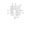
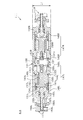
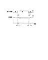
- FIG. 6 is a cross-sectional view showing the internal configuration of the pump 111.
- the pump 111 is a twin diaphragm pump, and includes a first valve unit 111L having a valve member 147L, a second valve unit 111R having a valve member 147R, and a connecting body 131.
- the connection body 131 is connected by screwing with the first valve unit 111L and the second valve unit 111R facing each other at both ends thereof.
- the pump 111 has a thin rectangular parallelepiped outer shape in which the thickness L1 is suppressed by improving the efficiency of equipment arrangement (described later).
- the connection body 131 is made of, for example, a fluororesin and is also called a connection part.
- the first valve unit 111L and the second valve unit 111R have the same configuration (or a symmetric configuration), and are fastened (screwed) to the connecting body 131 in directions opposite to each other.
- the valve member 147L is configured by integrating a diaphragm valve body 149L and a rod 148L, and the diaphragm valve body 149L is connected to one end of the rod 148L.
- the valve member 147R is configured by integrating a diaphragm valve body 149R and a rod 148R, and the diaphragm valve body 149R is connected to one end of the rod 148R.
- the diaphragm valve body 149L and the diaphragm valve body 149R are made of, for example, a fluororesin.
- the diaphragm valve body 149 ⁇ / b> L and the diaphragm valve body 149 ⁇ / b> R form surfaces that face each other in the pump chamber 158.
- the diameter of the diaphragm valve body 149L and the diaphragm valve body 149R can be suppressed while ensuring the volume change amount of the pump chamber.
- Such suppression of the diameter can provide a degree of design freedom for suppressing the thickness L1 by reducing the size of the pump chamber 158.
- the first valve unit 111L and the second valve unit 111R are also referred to as a first diaphragm driving unit and a second diaphragm driving unit, respectively.
- the diaphragm valve body 149L and the diaphragm valve body 149R are also referred to as a first diaphragm and a second diaphragm, respectively.
- the connecting body 131 forms a pump chamber 158 together with the diaphragm valve body 149L and the diaphragm valve body 149R, and a suction passage 137 and a discharge passage 138 are connected to the pump chamber 158.
- the connecting body 131 has a rectangular parallelepiped outer shape having an upper surface 131t and a bottom surface 131b.
- the pump 111 is configured such that the upper surface 131t is disposed on the upper side and the bottom surface 131b is disposed on the lower side with respect to the direction of gravity in the equipped state, and is parallel to the horizontal plane.
- the diaphragm valve body 149L and the diaphragm valve body 149R are arranged at positions (opposite positions) that sandwich the pump chamber 158 from both sides.
- a space for arranging the components of these valve units 111L and 111R is effectively provided in a direction extending in the opposing direction of the first valve unit 111L and the second valve unit 111R.
- the distance between the upper surface 131t and the bottom surface 131b can be reduced, and the height L1 of the pump 111 in the direction of gravity can be reduced.
- a suction passage 137 and a discharge passage 138 are arranged in a direction perpendicular to the direction (opposing direction) in which the diaphragm valve body 149L and the diaphragm valve body 149R operate, as shown in FIG.
- the suction side valve 113 and the discharge side valve 114 are connected.
- the horizontal plane means a horizontal plane based on the direction of gravity.
- the present inventor can reduce the size of the pump chamber 158 by the opposing operation of the diaphragm valve body 149L and the diaphragm valve body 149R, and realize an efficient equipment arrangement in a horizontal plane with almost no waste.
- the thickness L1 of 111 has been successfully reduced.
- the suction passage 137 and the discharge passage 138 are arranged in a direction perpendicular to the direction (opposing direction) in which the diaphragm valve body 149L and the diaphragm valve body 149R operate, but they are not necessarily vertical. It is not necessary and any direction that intersects is sufficient. However, the closer to the vertical, the better the equipment efficiency.
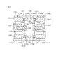
- FIG. 7 is an enlarged cross-sectional view showing the internal structure of the connecting body 131.
- a plurality of through holes having different inner diameters communicate with the connecting body 131 in the moving direction (opposing direction) of the rod 148L and the rod 148R.
- the plurality of through holes are a pair of outer through holes 135a and 135e, a pair of inner through holes 135b and 135d, and a central through hole 135c in order from the outside of the connecting body 131, as coaxial through holes (a common central axis). Communicate.
- this communication is configured as a coaxial communication state having a common central axis.
- the outer through holes 135a and 135e and the inner through holes 135b and 135d each have a cylindrical shape with a constant inner diameter.
- the central through hole 135c has a shape in which the inner diameter increases as it approaches the central portion (the deepest portion).
- the discharge passage 138 is connected to the top in the direction of gravity, and the suction passage 137 is connected to the lowest portion. Due to the internal shape and connection state of the central through-hole 135c, even if bubbles are generated inside the pump chamber 158, the liquid material sucked from the suction passage 137 is smoothly discharged from the discharge passage 138. .
- the stem 132L of the first valve unit 111L is screwed into the outer through hole 135a.
- the stem 132L has a valve support hole 143L through which the rod 148L is inserted.
- a central portion side of the diaphragm valve body 149L is connected to the rod 148L.
- the outer edge portion 150L on the end side of the diaphragm valve body 149L is sandwiched between the stem 132L and the support portion 135f of the connection body 131.
- the donut-shaped region (membrane region) between the center side and the end side of the diaphragm valve body 149L has a convex shape that protrudes toward the rod 148L side, and is smooth as the rod 148L reciprocates. It is configured to be elastically deformable.
- the stem 132R of the second valve unit 111R is screwed into the outer through hole 135e of the connecting body 131.
- the outer edge portion 150R on the end side of the diaphragm valve body 149R is sandwiched between the stem 132R and the support portion 135g of the connection body 131.
- Each component of the second valve unit 111R that is, the stem 132R, the rod 148R, and the outer edge portion 150R has a symmetric configuration with each component of the first valve unit 111L. Since the second valve unit 111R has a symmetric configuration with each component of the first valve unit 111L, the details of the configuration of the second valve unit 111R will be described below. Will be replaced with the description of the first valve unit 111L.
- the first valve unit main body 131L is screwed into the thread portion of the stem 132L. As shown in FIG. 6, the first valve unit main body 131L is formed with a substantially cylindrical cylinder portion 142L that opens to the connection body 131 side, and a stem support hole 144L that communicates with the cylinder portion 142L. ing. The stem 132L is screwed into the screw portion of the stem support hole 144L.
- the first valve unit main body 131L is made of a lightweight material such as polypropylene resin or aluminum.
- a guide support portion 146 ⁇ / b> L is formed on the stem 132 ⁇ / b> L on the opposite side of the connection body 131.
- the guide support portion 146L is configured as a convex portion having a cylindrical shape that supports the guide 145L.
- the guide 145L is a member having a cylindrical shape disposed inside the guide support portion 146L, and supports the rod 148L so that it can slide in the moving direction of the rod 148L.
- the rod 148L is formed with a substantially disc-shaped piston portion 151L having the same outer diameter as the inner diameter of the cylinder portion 142L.
- the outer periphery of the piston portion 151L is in contact with the inner surface of the cylinder portion 142L, and is slidably accommodated in the cylinder portion 142L.
- the cylinder part 142L is partitioned into two spaces by the piston part 151L of the rod 148L. Of these two spaces, the space on the stroke limiting member 157L side of the piston portion 151L is a pressure control chamber 141L. Operation air is introduced into the pressure control chamber 141L from the outside through an air introduction passage 134L formed in the first valve unit main body 131L, thereby connecting the valve member 147L by pressurizing the pressure control chamber 141L. It can be moved to the body 131 side.
- the stem 132L urges the rod 148L in the direction opposite to the connection body 131 by a spiral coil-shaped spring 156L through the piston portion 151L. Thereby, the reciprocating movement of the rod 148L is realized.
- the stroke restriction member 157L has a screw portion 155L, and is screwed to the first valve unit main body 131L by the screw portion 155L.
- the screw portion 155L moves (adjusts) the stroke limiting member 157L relative to the first valve unit main body 131L by relative rotation between the stroke limiting member 157L and the first valve unit main body 131L. be able to.
- the stroke limit member 157L can limit the movement range of the rod 148L to be adjustable on the side opposite to the connection body 131 by this relative movement.
- the movement range of the rod 148L is fixedly limited by the guide support portion 146L on the connection body 131 side.
- the movement ranges of the rod 148L and the rod 148R are also referred to as a first displacement amount and a second displacement amount, respectively.
- the stroke limiting member 157L is fixed by a double nut using an upper nut 159L and a lower nut 160L.
- the upper nut 159L further uses the stud 164L to suppress relative rotation with the stroke limiting member 157L.
- the stroke limiting member 157L can be adjusted in the state where the lower nut 160L is loosened after the upper nut 159L is loosened in the state where the stud 164L is loosened.
- the rotation angles of the stroke limiting member 157L and the stroke limiting member 157R can be confirmed by scales (not shown) formed on the first valve unit main body 131L and the first valve unit main body 131R, respectively.
- This scale is realized by the same configuration (angle measuring unit) as the micrometer capable of measuring the range of movement of the stroke limiting member 157L and the stroke limiting member 157R in units of microns.
- the stroke limiting member 157L and the stroke limiting member 157R are also referred to as a first displacement limiting portion and a second displacement limiting portion, respectively.
- the rotation of the stroke limiting member 157L and the stroke limiting member 157R is also referred to as a first rotation and a second rotation, respectively.
- This discharge amount means the amount for each stroke.
- Such a configuration can also be realized in various forms such as a dial gauge and a digital micrometer that indicate values related to the discharge amount measured according to the rotation angle, and is also called a measurement unit.
- the value related to the discharge amount has a broad meaning including a value related to the discharge amount, such as the feed amount of the stroke limit member 157L and the stroke limit member 157R caused by the rotation angle.
- the strokes of the rod 148L and the rod 148R are set so that only 100 ⁇ L of liquid material is discharged by one reciprocating operation.
- the reciprocating operation is performed at a cycle of 6 times per minute, vaporization can be performed at a rate (speed) of 600 ⁇ L per minute.
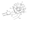
- FIG. 8 is a perspective view showing the appearance of the vaporizer 112 of the second embodiment.
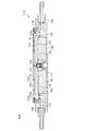
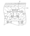
- FIG. 9 is a cross-sectional view showing a cross section of the vaporizer 112 of the second embodiment.
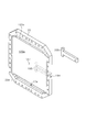
- FIG. 10 is a perspective view showing the heat storage plate 123 of the vaporizer 112.
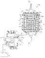
- FIG. 11 is an internal structure diagram of the inside of the vaporizer 112 of the second embodiment as viewed from below.
- FIG. 12 is a bottom view showing a state where the heater 122 of the vaporizer 112 is viewed from below.
- FIG. 13 is a bottom view showing a state in which the back cover 136 of the vaporizer 112 is viewed from below.
- the downward direction refers to the direction opposite to the cover 121 in the orientation of the vaporizer 112 with respect to gravity.
- the vaporizer 112 of the second embodiment has a structure in which a cover 121, a heat storage plate 123, and a vaporizer main body 133 are sequentially stacked, and the thickness L ⁇ b> 2 is suppressed similarly to the pump 111. It has a thin rectangular parallelepiped shape.
- the cover 121 is made of a transparent resin, but may be made of an opaque material.
- the heat storage plate 123 is made of a rectangular plate formed of silicon carbide or aluminum material having excellent thermal conductivity. However, if it comprises a transparent material, there exists an advantage that the state of vaporization can be confirmed visually. If the vaporizer 112 is arranged in the same plane as the pump 111, the entire liquid vaporizer 120 can be configured as a thin system.
- the liquid material is supplied between the liquid adhesion surface 123a and the mesh 124 via the orifice 127 formed in the heat storage plate 123, and is opposite to the liquid adhesion surface 23a.
- This is different from the first embodiment (see FIG. 2) in which the liquid is dropped onto the mesh 24 from the side (upper side).
- the liquid material can flow through the gap between the mesh 124 and the liquid adhesion surface 123a due to the interfacial tension, so that the liquid material can be supplied to a wide area of the mesh 124.
- the heat storage plate 123 is formed with an orifice 127 at a substantially central portion thereof, and a liquid material can be supplied from a substantially central portion of the liquid adhesion surface 123a.
- a shutoff valve 180 is connected to the orifice 127 so that the flow of the liquid material can be shut off at the orifice 127.
- the shutoff valve 180 is supplied with a flow path unit 116 in which an internal flow path 115 for supplying a liquid material is formed, and working air used for controlling the supply of the liquid material.
- the piping 191 to be connected is connected in a direction in which the shutoff valve 180 is sandwiched. This direction is oriented substantially perpendicular to the direction in which the heat storage plate 123 is sandwiched between the gas introduction pipe 128 and the gas introduction pipe 129.
- shutoff valve 180 two heaters 122 (see FIG. 12) that supply heat to the heat storage plate 123 are provided in the recess 139 of the vaporizer main body 133 on the back surface of the vaporizer main body 133 on the lower surface of the heat storage plate 123.
- the flow path unit 116 and the pipe 191 are disposed on the lower surfaces of the two heaters 122 in the recess 139.
- a heat insulating material 192 having elasticity is disposed around the shutoff valve 180, the flow path unit 116, and the pipe 191, and on the lower surface of each heater 122.
- a back cover 136 (see FIG. 13) is fixed to the back surface of the vaporizer 112 in a state where the heat insulating material 192 is elastically deformed (a state where a load is applied). In FIG. 11, some components (the back cover 136 and the heat insulating material 192) are omitted to show the internal structure.
- the heater 122 is configured by a rubber heater formed in an L-shaped flat plate shape as shown in FIG.
- the rubber heater is a heater in which the heating wire is covered with flexible thin silicon rubber, and has an advantage that it can be surely fitted to the heating surface and is easily assembled.
- the mesh 124 is formed by weaving a plurality of stainless steel wires 24a arranged vertically and horizontally in the form of a mesh as in the first embodiment. I am doing.
- the heat storage plate 123 has a liquid adhesion surface 123a that is significantly larger than that of the first embodiment.
- the liquid adhesion surface 123a is formed with a recess 194 in which a thermocouple 195 is disposed on the back surface. Since the recessed part 194 is formed in the back surface (surface on the opposite side to the liquid adhesion surface 123a) of the thermal storage plate 123, the airtightness of the liquid adhesion surface 123a side can be ensured.
- the recess 194 further measures the temperature of the liquid adhesion surface 123a accurately and with a small time delay by forming a deep recess near the liquid adhesion surface 123a, that is, by reducing the plate thickness between the recess 194 and the liquid adhesion surface 123a. be able to.
- thermocouple 195 is connected to the controller 40, and is used for monitoring the vaporization state in this embodiment.
- a thermocouple cover 193 that covers the thermocouple 195 is attached to the recess 194.
- FIG. 10 shows a state in which the thermocouple cover 193 is removed for easy understanding. The state monitoring method will be described later.
- the mesh 124 is pressed against the liquid adhesion surface 123a by a plurality of pins 124f arranged at a predetermined pitch so as not to be excessively separated from the liquid adhesion surface 123a.
- the plurality of pins 124f are made of, for example, a fluororesin, and are fixed to the cover 121. With such a configuration, the liquid material can flow through the gap between the mesh 124 and the liquid adhesion surface 123a due to the interfacial tension, so that the liquid material can be supplied to a wide area of the mesh 124.
- One of the plurality of pins 124f is disposed at a position facing the outlet of the orifice 127. Thereby, the collision with the cover 121 resulting from the deformation
- the outlet of the orifice 127 is also called a supply port.
- the pin 124f may be configured as a plurality of members arranged at a plurality of positions for pressing the mesh, or may include a common member having a plurality of convex portions for pressing.
- the mesh 124 faces a vaporization channel 175 through which nitrogen gas flows, and the vaporized liquid material is mixed with the nitrogen gas.
- Nitrogen gas is supplied to the vaporization flow path 175 through the introduction passage 174 and the groove 123b of the gas introduction pipe 128 in this order.
- the groove portion 123b is formed so that the nitrogen gas supplied from the introduction passage 174 can be dispersed in the horizontal plane and supplied to the mesh 124.
- nitrogen gas mixed with a liquid material is discharged from the vaporization flow path 175 through the groove portion 123c and the discharge passage 176 of the gas introduction pipe 129 in order.
- the groove portion 123 c is formed so that the mixed gas can be collected from the wide surface of the mesh 124 and discharged to the discharge passage 176.
- the vaporization channel 175 is airtight by a gasket 123 g provided between the cover 121 and the heat storage plate 123.
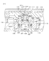
- FIG. 14 is a cross-sectional view showing a cross section of the vaporizer 112.
- FIG. 15 is an enlarged cross-sectional view showing a state where the shutoff valve 180 closes the orifice 127.
- FIG. 16 is an enlarged cross-sectional view showing a state where the shutoff valve 180 opens the orifice 127.
- the vaporizer 112 of the second embodiment is different from the liquid material supply method of the first embodiment in that a shutoff valve 180 is provided in the liquid material supply path.
- the shut-off valve 180 can effectively suppress the leakage of the liquid material and the generation of bubbles in the supply channel due to the vaporization of the liquid material in the supply channel after the supply of the liquid material is stopped. . Since the occurrence of such leakage or bubbles causes an error in the supply amount of the liquid material, this embodiment effectively suppresses such an error and significantly improves the accuracy of the supply amount of the liquid material. Has the advantage of being able to.
- a liquid material is supplied to the shutoff valve 180 via an internal flow path 115 formed in the flow path unit 116.
- the shutoff valve 180 can operate the supply of the liquid material to the orifice 127 using the operation air supplied through the pipe 191.
- a diaphragm valve 180 is connected to the orifice 127. As shown in FIGS. 15 and 16, the shut-off valve 180 can open and close the orifice 127 by moving the diaphragm valve 181 in the flow direction of the orifice 127. As described above, in the second embodiment, the orifice 127 formed inside the heat storage plate 123 is directly blocked by the diaphragm valve 181, so that the amount of vaporization caused by the liquid material remaining in the discharge passage is changed. Inconvenience can be avoided. This is because the amount remaining in the discharge passage is extremely small, and since it is immediately vaporized by heat, it does not cause fluctuation.
- the orifice 127 is formed inside the heat storage plate 123 as a flow path between the outlet on the mesh 124 side and the inlet on the shut-off valve 180 side.
- the outlet on the mesh 124 side is also called a supply port.
- the inlet on the shut-off valve 180 side is formed in a recess that forms a flow path chamber 181r, and has a valve seat 181v.
- the inlet on the side of the shut-off valve 180 is also called a back opening, and is formed at a position facing the supply port at the orifice 127.
- the present inventors have found that the operation of the diaphragm valve 181 has a slight influence (reduction) on the discharge amount of the liquid material.
- the inventor has found that the influence on the discharge amount is caused by the volume expansion of the flow path chamber 181r due to the operation of the diaphragm valve 181. This is because the expansion of the volume of the flow path chamber 181r absorbs a part of the liquid material supplied to the shutoff valve 180 and reduces the supply amount to the orifice 127.
- the present inventor has found that the volume expansion has reproducibility, and has also found that it can be easily solved by setting a discharge amount in anticipation of a discharge amount reduction due to the volume expansion.
- a rod 182 is connected to the diaphragm valve 181.
- a sliding portion 184 and a piston portion 183 are formed on the rod 182.
- the sliding portion 184 slides inside a guide portion 189 that is a cylindrical recess formed in the shut-off valve body 185.
- the piston portion 183 slides inside a cylinder portion 188 formed in communication with the guide portion 189 inside the shut-off valve body 185, thereby defining a pressure control chamber 183a.
- the rod 182 is urged by a spiral coil-shaped spring 187 in the direction of closing the orifice 127 by the diaphragm valve 181 and can be operated in the direction of opening the orifice 127 by pressurization of the pressure control chamber 183a.
- the spring 187 is fixed by a back cover 186.
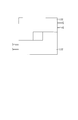
- FIG. 17 is a graph showing the relationship between the open / closed state of the shut-off valve 180 and the temperature measured by the thermocouple 195 (see FIG. 10).
- the horizontal axis represents time, and the vertical axis represents the open / close state of the valve and the measured temperature.
- a curve C1 is a curve showing the open / closed state of the shut-off valve 180.
- a curve C2 is a curve indicating the measured temperature of the thermocouple 195.
- the reason why the temperature is measured by the thermocouple 195 is that the thermocouple has a high responsiveness and has a preferable characteristic for detecting a minute temperature change caused by the start and end of vaporization.
- the vaporization state of the liquid material is monitored as follows. At time t1, the controller 40 supplies operating air from the pipe 191 to change the shutoff valve 180 from the closed state (see FIG. 15) to the open state (see FIG. 16). The controller 40 starts monitoring the measured temperature of the thermocouple 195 in response to the start of the open state of the shutoff valve 180 (start of supply of liquid material), and measures the elapsed time P1 until a temperature drop due to vaporization is detected. To do. Based on the elapsed time P1 until the start of vaporization and a preset reference range, the controller 40 may confirm that the process from the start of liquid material supply to the start of vaporization is normal. it can.
- the controller 40 starts monitoring the measured temperature of the thermocouple 195 in response to the closing state start of the shutoff valve 180 (end of supply of the liquid material), and the process until the temperature increase due to the end of vaporization is detected.
- Time P2 is measured. Based on this elapsed time P2 and a preset reference range, the controller 40 can confirm that the process from the completion of the supply of the liquid material to the completion of the vaporization is normal. Furthermore, the detection of the temperature rise can be detected also as an unexpected end of vaporization during the vaporization process (abnormality detection).
- the temperature control of the heat storage plate 123 is substantially performed based on the observation result of the vaporization state of the liquid material.
- the heat storage of the heat storage plate 123 is used so that the change becomes gentle.
- temperature feedback is performed using the temperature measured in the region where the temperature change is most severe among the liquid adhering surfaces 123a. As a result, the amount of heat supplied by the heater 122 is suppressed, and control with a small temperature change and high responsiveness is realized.
- thermocouple 195 is preferably disposed in the vicinity of the orifice 127. In this way, the vaporization state at the position where the liquid material is first supplied by the start of the supply of the liquid material can be monitored, and the vaporization state at the position where the liquid material remains until the end when the supply of the liquid material is stopped is monitored. Because it can.
- Such an arrangement also has the advantage that the entire vaporization process can be monitored.
- the point of shortening the length of the orifice 127 and arrange it at a position closest to the orifice 127 in a position where the cutoff valve 180 is avoided, that is, a position adjacent to the cutoff valve 180.
- the temperature control of the heat storage plate 123 is on / off control, it is preferable to open and close the shutoff valve 180 in a state where the influence of the transient response due to the energization operation (energization on or energization off) is small.
- a filter for extracting the waveform may be used. Specifically, for example, a time series data of a certain period of time after opening / closing the shut-off valve 180 may be acquired, and a waveform peak of a specific wavelength may be detected by fast Fourier transform. In this way, it is possible to monitor the vaporization state with high accuracy.
- the vaporization state can be monitored using the temperature change of the heat storage plate 123 caused by the heat of vaporization.
- the vaporization process can be reliably monitored, and the failure detection can be realized to improve the quality of the semiconductor process.
- the second embodiment can obtain the same effect as the effect obtained by the supply method of the first embodiment, suppress the scattering of the liquid material, and the liquid material.
- advantages such as expansion of the vaporization area and stabilization (high accuracy) of the supply amount of the liquid material.
- the use of the mesh 24 promotes the wetting of the liquid material with respect to the liquid adhesion surface 23a and succeeds in expanding the vaporization area as compared with the prior art.
- the liquid material is further supplied from the back side of the mesh 124, even if the liquid material is pressurized and supplied, it is caused by the collision of the discharged liquid material with the mesh 124. Scattering (misting) in the liquid state of the liquid material can be suppressed.
- the pressurized supply of the liquid material can suppress leakage by making the mesh 124 dense with the reaction force from the pin 124f provided at a position facing the supply port. With such a mechanism, the supply speed can be further increased in the second embodiment.
- the liquid material scatters when the liquid material collides with the mesh 24 and scatters and adheres to an unheated discharge side (for example, in the vicinity of the nozzle 27 (see FIG. 2)), thereby solidifying the liquid material without evaporating.
- an unheated discharge side for example, in the vicinity of the nozzle 27 (see FIG. 2)
- the solid material obtained by solidifying the liquid material is peeled off and then supplied to the process object together with nitrogen gas, which may cause quality deterioration of the process object.
- the vaporization area of the liquid material is significantly increased. can do.
- the vaporization flow path 175 is made thin in the vertical direction (gravity reference) while expanding the vaporization area of the liquid material, or the cover 121 and the liquid adhesion surface 123a. Therefore, the vaporizer 112 can be made thinner.
- the orifice 127 formed inside the heat storage plate 123 heated as described above is directly blocked by the diaphragm valve 181, so Inconveniences such as fluctuations in the amount of vaporization due to the remaining liquid material can be avoided. Furthermore, since the diaphragm valve 181 does not expose the sliding portion in the flow path, it is possible to prevent the generation of solid matter due to the accumulation of the liquid material in the sliding portion. Thereby, generation
- the vaporizer 112 supplies the liquid material between the mesh 124 and the liquid adhesion surface 123a, thereby suppressing the scattering of the liquid material and effectively using the interfacial tension, thereby supplying a high amount of the liquid material. Realize speed. Furthermore, since the shutoff valve 180 is equipped as an integrated form in the recess formed in the heat storage plate 123, the thickness of the vaporizer 112 can be reduced while maintaining the heat storage amount of the heat storage plate 123. .
- the liquid material is expanded into a thin film using the meshes 24 and 124, but the liquid material may be expanded into a thin film using other means.
- two liquid adhering surfaces facing each other may be disposed with a predetermined gap, and the liquid material may be injected into the gap to expand the liquid material into a thin film shape using a capillary phenomenon.
- a vaporizer 70 shown in FIG. 18 is provided in the liquid vaporization system.
- the vaporizer 70 in this example includes a fixed portion 71 that constitutes the base of the vaporizer 70 and a moving portion 72 that is provided on the upper side of the fixed portion 71 and is movable in the vertical direction.
- the fixing part 71 includes a base part 73 formed in a disk shape, a lower heater 74 as a heating means, and a heat insulating material 75.
- the base portion 73 is made of aluminum having excellent thermal conductivity, for example, and is provided in a substantially horizontal state.
- the base portion 73 is provided with a protruding portion 76 that protrudes upward.
- the protrusion 76 is formed in an annular shape as a whole, and an inner region surrounded by the protrusion 76 is a disposition space 81 in which a part of the moving portion 72 is disposed.
- the protrusion 76 is formed with an introduction port 79 that communicates with the installation space 81 via the introduction passage 77 and a discharge port 80 that communicates with the installation space 81 via the discharge passage 78.
- An introduction pipe (not shown) leading to the nitrogen gas source is connected to the introduction port 79, and a discharge pipe (not shown) leading to the chamber is connected to the discharge port 80.
- a supply pipe 83 for supplying a liquid material is provided in the base portion 73 so as to penetrate the base portion 73 vertically.
- the supply pipe 83 communicates with the arrangement space 81 at a substantially central position of the arrangement space 81 in plan view.
- the lower heater 74 is constituted by, for example, a sheet-like rubber heater, and is formed in a disk shape with a diameter larger than the outer diameter of the arrangement space 81 (in other words, the inner diameter of the protruding portion 76).
- the lower heater 74 is overlaid on the lower surface of the base portion 73, and specifically, is provided so as to overlap the entire arrangement space 81 in plan view.
- the heat insulating material 75 is made of glass wool formed in a disk shape.
- the heat insulating material 75 is provided so as to spread over the entire base portion 73 below the base portion 73 and the lower heater 74.
- the moving unit 72 includes a housing member 86, a heat storage plate 87 and an upper heater 88 housed in the housing member 86.
- the housing member 86 includes a cylindrical housing portion 86a that is open at the top and bottom, and a flange portion 86b that is provided at the upper end of the housing portion 86a.
- the heat storage plate 87 is made of the same material as that of the base portion 73 and is made of a disc having an outer diameter that is substantially the same as the inner diameter of the housing portion 86 a of the housing member 86.
- the heat storage plate 87 is disposed at the lower end portion inside the accommodating portion 86a of the accommodating member 86, and the side surface thereof faces the inner side surface of the accommodating portion 86a.
- the lower surface of the heat storage plate 87 is set at the same height as the lower end of the housing portion 86a or at a lower position.
- the upper heater 88 is composed of, for example, a sheet-like rubber heater, like the lower heater 74, and is formed in a disk shape with substantially the same outer dimensions as the heat storage plate 87.
- the upper heater 88 is disposed in the housing portion 86 a of the housing member 86 and is superimposed on the upper surface of the heat storage plate 87.
- a lid portion 91 having a concave portion 91a that opens upward is provided, and a heat insulating material 92 is disposed in the concave portion 91a.
- a plate-like cover 93 is provided on the heat insulating material 92, and is fixed to the flange portion 86 b of the housing member 86 with bolts 101.
- a flat plate member 94 is provided on the upper surface of the flange portion 86b of the housing member 86 so as to protrude laterally from the flange portion 86b.
- a plurality of (for example, four) plate members 94 are provided at predetermined intervals along the outer circumferential direction of the flange portion 86b, and each plate member 94 is fixed to the flange portion 86b by a bolt 102.
- the moving part 72 configured as described above is disposed on the fixed part 71 in a state where a part of the moving part 72 is dropped into the disposing space 81.
- the lower surface of the heat storage plate 87 faces the upper surface of the base portion 73 with a predetermined gap therebetween, and this gap (specifically, the housing portion 86a of the housing member 86 and the base portion).
- 73 also includes a gap between the projecting portion 76 and the projecting portion 76) to form a vaporizing chamber 97 for vaporizing the liquid material.
- the flange portion 86b of the housing member 86 is disposed on the protruding portion 76 of the base portion 73, and a bellows 98 is provided between the flange portion 86b and the protruding portion 76 so as to straddle both the portions 76 and 86b.
- the bellows 98 is a partition member for partitioning the inside and outside of the vaporizing chamber 97, and is configured to be extendable in the vertical direction.
- the supply pipe 83 communicates with the vaporization chamber 97.
- a liquid material is supplied to the vaporizing chamber 97 via a supply pipe 83.
- the vaporization chamber 97 communicates with the introduction port 79 through the introduction passage 77 and communicates with the discharge port 80 through the discharge passage 78.
- Nitrogen gas is supplied to the vaporizing chamber 97 via the introduction port 79, and the supplied nitrogen gas and the vaporized liquid material are supplied to the chamber via the discharge port 80.
- the elevating device 99 includes a cylinder main body 99a fixed on the base portion 73 of the fixing portion 71, and a piston rod 99b that elevates when operating air is introduced into the cylinder main body 99a.
- Each plate member 94 is fixed to the upper surface of the piston rod 99b with a bolt, so that when the piston rod 99b moves up and down, each plate member 94 moves up and down, and as a result, the moving portion 72 moves up and down.
- the moving unit 72 includes a lower position where the lower surface of the heat storage plate 87 is close to the upper surface of the base portion 73 (see FIG.
- the gap between the lower surface of the heat storage plate 87 and the upper surface of the base part 73 is 20 to 60 ⁇ m, and when the moving part 72 is in the upper position, The gap is 2 mm.
- the liquid material has a contact angle larger than 90 ° with the liquid adhesion surface (specifically, the surface of the base portion 73 and the heat storage plate 87).
- the lifting device 99 is driven to move the moving unit 72 to the lower position.
- the pump is discharged to supply the liquid material to the vaporizing chamber 97 via the supply pipe 83.
- the liquid material is formed into a thin film by capillary action on the side away from the supply port (not shown) of the supply pipe 83 through the gap between the lower surface of the heat storage plate 87 and the upper surface of the base portion 73. spread.
- the liquid material expands in a circle around the supply port of the supply pipe 83.
- the lifting device 99 is driven to move the moving unit 72 to the upper position.
- the liquid material adheres to the lower surface of the heat storage plate 87 and the upper surface of the base portion 73 in a thin film state, and the liquid material adhering to the respective surfaces passes through the respective surfaces to the heater 74. , 88 is heated and vaporized.
- nitrogen gas is introduced into the vaporizing chamber 97 from the introduction port 79. Thereby, the vaporized liquid material is supplied to the chamber through the discharge port 80 together with the nitrogen gas introduced into the vaporization chamber 97.
- the liquid material can be spread in a thin film shape by a capillary phenomenon in the gap between the lower surface of the heat storage plate 87 and the upper surface of the base portion 73, the lower surface of the heat storage plate 87 and the upper surface of the base portion 73.
- a liquid material can be attached in a thin film.
- the liquid material adhering to each of those surfaces can be heated by the heaters 74 and 88 via the respective surfaces, that is, the liquid material can be heated via the two liquid adhering surfaces, The vaporization of the material can be further promoted.
- the configuration is provided in which the uneven portion is provided on the liquid adhesion surface by using the meshes 24 and 124, but the configuration in which the uneven portion is provided is not limited thereto.
- the uneven portion may be provided by processing the surface of the liquid adhesion surface into an uneven shape without using the mesh 24. In this case, since it is not necessary to provide a separate member for providing the uneven portion, the number of parts can be reduced.
- the convex portions 52 and the concave portions 53 are alternately arranged on the heat storage plate 23 along two orthogonal directions parallel to the upper surface 23a of the heat storage plate 23. There is no need to have two different directions. Moreover, it is good also as a structure which arrange
- FIG. 1 is a structure which arrange
- the meshes 24 and 124 made of stainless steel are used, but the mesh is not necessarily made of stainless steel, and meshes made of other metals may be used. Further, a resin mesh made of a fluororesin or the like may be used. Moreover, in the said embodiment, although the thing of 100 mesh roughness was used as the mesh 24, you may use the mesh of other roughness. In short, a mesh having an appropriate roughness may be used according to the type of liquid material to be vaporized (specifically, wettability).
- the liquid material is supplied to the vaporizer 12 by the pump 11, but the liquid material may be supplied to the vaporizer 12 by using means other than the pump 11.
- the liquid material may be supplied to the vaporizer 12 by using means other than the pump 11.
- the liquid material is spread in a thin film by increasing the wettability of the liquid material.
- the liquid material may be spread in a thin film by other means.
- a configuration including a pair of flat plate members that are spaced apart from each other and a drive device that moves at least one of the plate members in a direction orthogonal to the plate surface is conceivable.
- the liquid material can be compressed by both plate members by supplying the liquid material between both plate members and then driving the driving device to bring one of the plate members closer to the other plate member, The liquid material can be spread like a thin film between both plate members.
- liquid vaporization system 10 is used in the semiconductor production line in the above embodiment, it can be used in other production lines. Moreover, in the said embodiment, although this system 10 was used in order to vaporize the hexamethyldisilazane liquid (HMDS liquid) as a liquid material, in order to vaporize other liquid materials, such as tetramethylcyclotetrasiloxane (TMCTS). You may use for.
- HMDS liquid hexamethyldisilazane liquid
- TCTS tetramethylcyclotetrasiloxane
- the liquid adhesion surface 123a has a planar shape, but it does not necessarily have to be a planar shape. Specifically, for example, it may have a gentle concave shape with the orifice 127 as the center, or may have a gentle convex shape with the orifice 127 as the center.
- the liquid attachment surface 123a does not have a groove or a partial projection, but for example, a groove (for controlling the flow of the liquid material between the mesh 124 and the liquid attachment surface 123a (You may make it form a bypass path and a convex part (detour element).
- the groove may include a radial shape extending from the orifice 127, for example.
- the liquid material supply port (the outlet of the nozzle 27 and the orifice 127) is single, but it is not necessarily required to be single, and a plurality of supply ports may be formed. However, if the number of supply ports is single, the amount of liquid material remaining in the supply port when the shutoff valve is closed can be suppressed.
- the mesh 124 is pressed against the liquid adhesion surface 123a by the plurality of pins 124f.
- a net (net) or a string fixed to the end of the liquid adhesion surface is attached to the liquid adhesion surface.
- a positioning member to be pressed may be used.
- the positioning member may include a spacer that is partially inserted to form a gap between the liquid adhesion surface and the mesh.
- the discharge amount is adjusted by confirming the rotation angles of the stroke limiting member 157L and the stroke limiting member 157R with a scale (not shown).
- the pump 111 is discharged from the suction side valve 113.
- the adjustment may be performed by confirming that the discharge amount is set in advance while operating the side valve 114 and monitoring the discharge amount.
- the discharge amount can be confirmed by checking the single or plural operation states (operation modes) assumed in actual operation such as discharge of only one when both the first valve unit main body 131L and the second valve unit 111R are operated. ).
- the shut-off valve 180 is formed in the recess in which the valve seat 181v (see FIG. 16) forms the flow channel chamber 181r, but other configurations are possible. That is, as shown in FIG. 19, for example, the valve seat 181v is not formed on the heat storage plate 123d side, and an annular protrusion 181p surrounding the back surface opening may be provided on the diaphragm valve 181a side. .
- the annular protrusion 181p is also called a sealing part.
- the height of the protrusion 181p of the diaphragm valve 181a can be configured to be about 0.5 mm, for example.
- the back surface opening is an inlet of the orifice 127 on the shutoff valve 180 side.
- the annular protrusion 181p is provided on the diaphragm valve 181a side as shown in FIG. 19, the back surface opening is inclined so as to rise in the direction of gravity toward the protrusion 181p. It may be. In this way, the bubbles can rise along the inclination, and the retention of bubbles can be further suppressed.
- valve seat and the sealing portion may be omitted.
- a configuration may be employed in which the valve seat and the protrusion are not provided to increase the surface pressure, but a flat surface facing the valve body may be provided. This is because no back pressure is applied at the time of interruption in the present invention.
Abstract
Description
前記加熱板には、前記液体付着面と反対側の面である裏面に形成されている裏面開口部と、前記供給口とを接続しているオリフィスが形成され、
前記裏面開口部を開閉する遮断弁を備え、
前記裏面開口部は、前記オリフィスを挟んで前記供給口と対向する位置に形成されていることを特徴とする。 In a liquid vaporization system according to an eighth aspect of the present invention, in the fifth to seventh aspects, the liquid adhesion surface is formed as a surface of a heating plate heated by the heating means,
The heating plate is formed with an orifice that connects a back surface opening formed on the back surface that is the surface opposite to the liquid adhesion surface, and the supply port,
Comprising a shut-off valve for opening and closing the back opening,
The back surface opening is formed at a position facing the supply port across the orifice.
前記裏面開口部は、前記凹部に形成され、
前記遮断弁は、前記裏面開口部を閉鎖する弁体を備えていることを特徴とする。 In the liquid vaporization system of the ninth invention, in the eighth invention, a recess is formed on the back surface of the heating plate,
The back opening is formed in the recess,
The shut-off valve includes a valve body that closes the back surface opening.
前記加熱板には、前記液体付着面の温度を計測するための温度センサが備えられていることを特徴とする。 In a liquid vaporization system according to a fourteenth aspect based on the first to thirteenth aspects, the liquid adhesion surface is formed as a surface of a heating plate heated by the heating means,
The heating plate is provided with a temperature sensor for measuring the temperature of the liquid adhesion surface.
前記ポンプは、第1のダイアフラム駆動部と、第2のダイアフラム駆動部と、前記第1のダイアフラム駆動部と前記第2のダイアフラム駆動部とを相互に対向させる方向で連結する連結部と、を備え、
前記連結部は、前記液体材料を吸入する吸入通路と、前記液体材料を吐出する吐出通路とが接続されたポンプ室を有し、
前記第1のダイアフラム駆動部は、前記ポンプ室の一部を構成する第1のダイアフラムを有し、
前記第2のダイアフラム駆動部は、前記ポンプ室の一部を構成する第2のダイアフラムを有し、
前記第1のダイアフラムと前記第2のダイアフラムとは、前記ポンプ室において相互に対向する面を形成し、
前記第1のダイアフラム駆動部は、前記第1のダイアフラムが機械的に変位可能な第1の変位量を制限し、前記第1の変位量が調整可能である第1の変位制限部を有し、
前記第2のダイアフラム駆動部は、前記第2のダイアフラムが機械的に変位可能な第2の変位量を制限し、前記第2の変位量が調整可能である第2の変位制限部を有することを特徴とする。 A liquid vaporization system according to a fifteenth aspect of the present invention includes the pump for supplying the liquid material to the vaporizer according to the first to fourteenth aspects of the invention.
The pump includes a first diaphragm driving unit, a second diaphragm driving unit, and a coupling unit that couples the first diaphragm driving unit and the second diaphragm driving unit in a direction facing each other. Prepared,
The connecting portion has a pump chamber to which a suction passage for sucking the liquid material and a discharge passage for discharging the liquid material are connected.
The first diaphragm driving unit has a first diaphragm constituting a part of the pump chamber,
The second diaphragm driving unit has a second diaphragm constituting a part of the pump chamber,
The first diaphragm and the second diaphragm form surfaces facing each other in the pump chamber,
The first diaphragm driving unit includes a first displacement limiting unit that limits a first displacement amount by which the first diaphragm can be mechanically displaced, and the first displacement amount is adjustable. ,
The second diaphragm driving unit includes a second displacement limiting unit that limits a second displacement amount by which the second diaphragm can be mechanically displaced and can adjust the second displacement amount. It is characterized by.
前記第2の変位制限部は、前記第2のダイアフラムの変位方向を軸線とし、前記ポンプに対する回転である第2の回転を行うことによって前記第2の変位量が調整可能であり、
前記ポンプには、前記第1の回転の角度と前記第2の回転の角度に応じて計測された吐出量に関係する値を示す計測部が設けられていることを特徴とする。 In a liquid vaporization system according to a sixteenth aspect based on the fifteenth aspect, the first displacement limiting portion performs a first rotation that is a rotation with respect to the pump, with a displacement direction of the first diaphragm as an axis. The first displacement amount can be adjusted by
The second displacement limiting unit can adjust the second displacement amount by performing a second rotation which is a rotation with respect to the pump, with a displacement direction of the second diaphragm as an axis.
The pump is provided with a measurement unit that indicates a value related to a discharge amount measured in accordance with the first rotation angle and the second rotation angle.
以下、本発明を具体化した第1の実施形態を図面に従って説明する。本実施形態は、半導体装置等の製造ラインにて使用される薬液供給システムについて具体化しており、まずは本システムの基本構成を図1の概略図に基づいて説明する。 (First embodiment)
A first embodiment of the present invention will be described below with reference to the drawings. The present embodiment embodies a chemical solution supply system used in a production line for semiconductor devices and the like. First, the basic configuration of the system will be described based on the schematic diagram of FIG.
次に、本発明の第2の実施形態について、図5を参照して第1の実施形態との相違点を中心に説明する。本実施形態の液体気化システム10は、液体気化装置120の構成とコントローラ40の制御内容とが第1の実施形態と相違し、その他の構成を共通にする。図5は、第2の実施形態の液体気化装置120の構成を示す平面図である。本実施形態の液体気化装置120は、メッシュ124を使用して液体材料を気化させる点で第1の実施形態と共通するが、本実施形態では、液体材料がメッシュ124と液体付着面(後述)との間に供給される点で相違する。 (Second Embodiment)
Next, a second embodiment of the present invention will be described with a focus on differences from the first embodiment with reference to FIG. The
本発明は上記実施形態に限らず、例えば次のように実施されてもよい。 (Other embodiments)
The present invention is not limited to the above embodiment, and may be implemented as follows, for example.
Claims (21)
- 液体材料を加熱して気化させる気化器を備えた液体気化システムであって、
前記気化器は、略平坦に形成され液体材料を付着させる液体付着面と、
前記液体付着面に付着した液体材料を薄膜化させる薄膜化手段と、
前記液体付着面を加熱する加熱手段と、
を備えることを特徴とする液体気化システム。 A liquid vaporization system including a vaporizer that heats and vaporizes a liquid material,
The vaporizer is formed substantially flat and has a liquid attachment surface to which a liquid material is attached;
A thinning means for thinning the liquid material adhering to the liquid adhering surface;
Heating means for heating the liquid adhesion surface;
A liquid vaporization system comprising: - 前記薄膜化手段は、前記液体付着面に対する液体材料の濡れを促進させる濡れ促進手段であり、前記濡れ促進手段により前記液体付着面に対する液体材料の濡れを促進させることで、前記液体付着面に付着した液体材料を薄膜化させることを特徴とする請求項1に記載の液体気化システム。 The thinning means is a wetting promoting means for promoting the wetting of the liquid material on the liquid adhering surface, and adheres to the liquid adhering surface by promoting the wetting of the liquid material on the liquid adhering surface by the wetting promoting means. The liquid vaporization system according to claim 1, wherein the liquid material is thinned.
- 前記濡れ促進手段は、液体材料に対する濡れ性を高めるべく前記液体付着面に設けられた微細な凹凸部であることを特徴とする請求項2に記載の液体気化システム。 3. The liquid vaporization system according to claim 2, wherein the wetting promotion means is a fine uneven portion provided on the liquid adhesion surface in order to improve wettability with respect to a liquid material.
- 前記液体付着面には、線材を網目状に編むことにより全体として平板状に形成されたメッシュが載せられているとともに、前記線材を凸部として前記線材により囲まれた部分を凹部として前記凹凸部が設けられていることを特徴とする請求項3に記載の液体気化システム。 The liquid adhering surface is provided with a mesh formed in a flat plate shape by knitting a wire into a mesh shape, and the uneven portion having a portion surrounded by the wire with the wire as a convex portion. The liquid vaporization system according to claim 3, wherein the liquid vaporization system is provided.
- 前記液体付着面には、前記液体付着面と前記メッシュとの間に前記液体材料を供給する供給口が形成されていることを特徴とする請求項4に記載の液体気化システム。 The liquid vaporization system according to claim 4, wherein a supply port for supplying the liquid material is formed between the liquid adhesion surface and the mesh on the liquid adhesion surface.
- 前記液体付着面と前記メッシュの積層方向の相対的な位置関係を決定する位置決め部材を備えることを特徴とする請求項5に記載の液体気化システム。 The liquid vaporization system according to claim 5, further comprising a positioning member that determines a relative positional relationship between the liquid adhesion surface and the mesh in the stacking direction.
- 前記位置決め部材は、前記位置決め部材は、所定の間隔で配置されている複数の位置で前記液体付着面に対して前記メッシュを押圧する押圧部材を備えることを特徴とする請求項6に記載の液体気化システム。 The liquid according to claim 6, wherein the positioning member includes a pressing member that presses the mesh against the liquid adhesion surface at a plurality of positions arranged at predetermined intervals. Vaporization system.
- 前記液体付着面は、前記加熱手段によって加熱される加熱板の表面として形成されており、
前記加熱板には、前記液体付着面と反対側の面である裏面に形成されている裏面開口部と、前記供給口とを接続しているオリフィスが形成され、
前記裏面開口部を開閉する遮断弁を備え、
前記裏面開口部は、前記オリフィスを挟んで前記供給口と対向する位置に形成されていることを特徴とする請求項5乃至7のいずれか一項に記載の液体気化システム。 The liquid adhesion surface is formed as a surface of a heating plate heated by the heating means,
The heating plate is formed with an orifice that connects a back surface opening formed on the back surface that is the surface opposite to the liquid adhesion surface, and the supply port,
Comprising a shut-off valve for opening and closing the back opening,
The liquid vaporization system according to any one of claims 5 to 7, wherein the back surface opening is formed at a position facing the supply port with the orifice interposed therebetween. - 前記加熱板の裏面には、凹部が形成され、
前記裏面開口部は、前記凹部に形成され、
前記遮断弁は、前記裏面開口部を閉鎖する弁体を備えていることを特徴とする請求項8に記載の液体気化システム。 A recess is formed on the back surface of the heating plate,
The back opening is formed in the recess,
The liquid vaporization system according to claim 8, wherein the shut-off valve includes a valve body that closes the back surface opening. - 前記弁体は、前記裏面開口部が閉鎖された状態において前記裏面開口部を囲む環状の突起部である封止部を有することを特徴とする請求項9に記載の液体気化システム。 10. The liquid vaporization system according to claim 9, wherein the valve body includes a sealing portion that is an annular protrusion that surrounds the back surface opening in a state where the back surface opening is closed.
- 前記裏面開口部は、前記凹部に形成されている弁座を有することを特徴とする請求項9に記載の液体気化システム。 10. The liquid vaporization system according to claim 9, wherein the back opening has a valve seat formed in the recess.
- 前記裏面開口部は、前記裏面開口部を囲む環状の領域に前記弁体に対向する平面を有することを特徴とする請求項9に記載の液体気化システム。 10. The liquid vaporization system according to claim 9, wherein the back surface opening has a flat surface facing the valve body in an annular region surrounding the back surface opening.
- 前記弁体は、前記裏面開口部を開閉するダイアフラムを有することを特徴とする請求項9乃至12のいずれか一項にに記載の液体気化システム。 The liquid vaporization system according to any one of claims 9 to 12, wherein the valve body includes a diaphragm that opens and closes the back surface opening.
- 前記液体付着面は、前記加熱手段によって加熱される加熱板の表面として形成されており、
前記加熱板には、前記液体付着面の温度を計測するための温度センサが備えられていることを特徴とする請求項1乃至13のいずれか一項に記載の液体気化システム。 The liquid adhesion surface is formed as a surface of a heating plate heated by the heating means,
The liquid vaporization system according to any one of claims 1 to 13, wherein the heating plate is provided with a temperature sensor for measuring the temperature of the liquid adhesion surface. - 前記液体材料を前記気化器に供給するポンプを備え、
前記ポンプは、第1のダイアフラム駆動部と、第2のダイアフラム駆動部と、前記第1のダイアフラム駆動部と前記第2のダイアフラム駆動部とを相互に対向させる方向で連結する連結部と、を備え、
前記連結部は、前記液体材料を吸入する吸入通路と、前記液体材料を吐出する吐出通路とが接続されたポンプ室を有し、
前記第1のダイアフラム駆動部は、前記ポンプ室の一部を構成する第1のダイアフラムを有し、
前記第2のダイアフラム駆動部は、前記ポンプ室の一部を構成する第2のダイアフラムを有し、
前記第1のダイアフラムと前記第2のダイアフラムとは、前記ポンプ室において相互に対向する面を形成し、
前記第1のダイアフラム駆動部は、前記第1のダイアフラムが機械的に変位可能な第1の変位量を制限し、前記第1の変位量が調整可能である第1の変位制限部を有し、
前記第2のダイアフラム駆動部は、前記第2のダイアフラムが機械的に変位可能な第2の変位量を制限し、前記第2の変位量が調整可能である第2の変位制限部を有することを特徴とする請求項1乃至14のいずれか一項に記載の液体気化システム。 A pump for supplying the liquid material to the vaporizer;
The pump includes a first diaphragm driving unit, a second diaphragm driving unit, and a coupling unit that couples the first diaphragm driving unit and the second diaphragm driving unit in a direction facing each other. Prepared,
The connecting portion has a pump chamber to which a suction passage for sucking the liquid material and a discharge passage for discharging the liquid material are connected.
The first diaphragm driving unit has a first diaphragm constituting a part of the pump chamber,
The second diaphragm driving unit has a second diaphragm constituting a part of the pump chamber,
The first diaphragm and the second diaphragm form surfaces facing each other in the pump chamber,
The first diaphragm driving unit includes a first displacement limiting unit that limits a first displacement amount by which the first diaphragm can be mechanically displaced, and the first displacement amount is adjustable. ,
The second diaphragm driving unit includes a second displacement limiting unit that limits a second displacement amount by which the second diaphragm can be mechanically displaced, and the second displacement amount is adjustable. The liquid vaporization system according to any one of claims 1 to 14, wherein: - 前記第1の変位制限部は、前記第1のダイアフラムの変位方向を軸線とし、前記ポンプに対する回転である第1の回転を行うことによって前記第1の変位量が調整可能であり、
前記第2の変位制限部は、前記第2のダイアフラムの変位方向を軸線とし、前記ポンプに対する回転である第2の回転を行うことによって前記第2の変位量が調整可能であり、
前記ポンプには、前記第1の回転の角度と前記第2の回転の角度に応じて計測された吐出量に関係する値を示す計測部が設けられていることを特徴とする請求項15に記載の液体気化システム。 The first displacement limiting unit can adjust the first displacement amount by performing a first rotation that is a rotation with respect to the pump, with a displacement direction of the first diaphragm as an axis.
The second displacement limiting unit can adjust the second displacement amount by performing a second rotation which is a rotation with respect to the pump, with a displacement direction of the second diaphragm as an axis.
16. The pump according to claim 15, wherein the pump is provided with a measuring unit that indicates a value related to a discharge amount measured according to the angle of the first rotation and the angle of the second rotation. The liquid vaporization system described. - 前記凹凸部は、多数の凹部と多数の凸部とからなり、
前記各凹部と前記各凸部とは前記液体付着面と平行な異なる二方向に沿ってそれぞれ交互に配置されていることを特徴とする請求項3又は4のいずれか一項に記載の液体気化システム。 The concavo-convex portion comprises a large number of concave portions and a large number of convex portions,
5. The liquid vaporization according to claim 3, wherein the concave portions and the convex portions are alternately arranged along two different directions parallel to the liquid adhesion surface. 6. system. - 前記気化器は、前記液体付着面を一対備えるとともに、これら各液体付着面が所定の隙間をあけて対向配置されており、
前記濡れ促進手段は、前記隙間内における液体材料の前記各液体付着面に対する濡れを毛細管現象により促進させるものであることを特徴とする請求項2に記載の液体気化システム。 The vaporizer includes a pair of the liquid attachment surfaces, and each of these liquid attachment surfaces is disposed opposite to each other with a predetermined gap therebetween.
3. The liquid vaporization system according to claim 2, wherein the wetting promotion means promotes wetting of the liquid material in the gap with respect to each liquid adhesion surface by a capillary phenomenon. - 前記気化器に供給通路を介して液体材料を供給するポンプと、
前記ポンプによる前記気化器への液体材料の供給量を調整する供給量調整手段と、
を備えることを特徴とする請求項1乃至18のいずれか一項に記載の液体気化システム。 A pump for supplying liquid material to the vaporizer via a supply passage;
Supply amount adjusting means for adjusting the supply amount of the liquid material to the vaporizer by the pump;
The liquid vaporization system according to any one of claims 1 to 18, further comprising: - 前記ポンプが液体材料を前記供給通路を介して前記気化器に供給した後、前記供給通路内に残った液体材料を吸引するよう制御するサックバック制御手段を備えることを特徴とする請求項19に記載の液体気化システム。 The suck back control means for controlling to suck the liquid material remaining in the supply passage after the pump supplies the liquid material to the vaporizer through the supply passage. The liquid vaporization system described.
- 前記ポンプと、前記気化器と、前記供給通路とを含んでユニット化された液体気化装置を備えることを特徴とする請求項19又は20に記載の液体気化システム。 21. The liquid vaporization system according to claim 19 or 20, further comprising a liquid vaporization apparatus unitized including the pump, the vaporizer, and the supply passage.
Priority Applications (5)
| Application Number | Priority Date | Filing Date | Title |
|---|---|---|---|
| CN201080027864.2A CN102470282B (en) | 2009-09-30 | 2010-03-30 | Liquid vaporization system |
| KR1020127008289A KR101234409B1 (en) | 2009-09-30 | 2010-03-30 | Liquid vaporization system |
| US13/498,902 US8361231B2 (en) | 2009-09-30 | 2010-03-30 | Liquid vaporization system |
| JP2010537983A JP4673449B1 (en) | 2009-09-30 | 2010-03-30 | Liquid vaporization system |
| TW099120490A TWI414361B (en) | 2009-09-30 | 2010-06-23 | Liquid vaporization system |
Applications Claiming Priority (2)
| Application Number | Priority Date | Filing Date | Title |
|---|---|---|---|
| JP2009226691 | 2009-09-30 | ||
| JP2009-226691 | 2009-09-30 |
Publications (1)
| Publication Number | Publication Date |
|---|---|
| WO2011040067A1 true WO2011040067A1 (en) | 2011-04-07 |
Family
ID=43825904
Family Applications (1)
| Application Number | Title | Priority Date | Filing Date |
|---|---|---|---|
| PCT/JP2010/055652 WO2011040067A1 (en) | 2009-09-30 | 2010-03-30 | Liquid vaporization system |
Country Status (6)
| Country | Link |
|---|---|
| US (1) | US8361231B2 (en) |
| JP (2) | JP4673449B1 (en) |
| KR (1) | KR101234409B1 (en) |
| CN (1) | CN102470282B (en) |
| TW (1) | TWI414361B (en) |
| WO (1) | WO2011040067A1 (en) |
Cited By (5)
| Publication number | Priority date | Publication date | Assignee | Title |
|---|---|---|---|---|
| JP2013078754A (en) * | 2012-02-27 | 2013-05-02 | Ckd Corp | Liquid control apparatus |
| US20130193230A1 (en) * | 2012-02-01 | 2013-08-01 | Ckd Corporation | Liquid control apparatus |
| US8752544B2 (en) | 2011-03-21 | 2014-06-17 | General Electric Company | Medical vaporizer and method of monitoring of a medical vaporizer |
| JP2015062254A (en) * | 2012-07-30 | 2015-04-02 | 株式会社日立国際電気 | Vaporizer, substrate processing device, and manufacturing method of semiconductor device |
| KR101928107B1 (en) | 2012-05-15 | 2018-12-11 | 시케이디 가부시키가이샤 | Liquid control apparatus |
Families Citing this family (17)
| Publication number | Priority date | Publication date | Assignee | Title |
|---|---|---|---|---|
| JP5368393B2 (en) * | 2010-08-05 | 2013-12-18 | 東京エレクトロン株式会社 | Vaporizer, substrate processing apparatus, and coating and developing apparatus |
| JP5810101B2 (en) | 2011-01-19 | 2015-11-11 | Ckd株式会社 | Liquid vaporizer |
| WO2012143840A1 (en) * | 2011-04-20 | 2012-10-26 | Koninklijke Philips Electronics N.V. | Measurement device and method for vapour deposition applications |
| KR101892758B1 (en) | 2011-09-30 | 2018-10-04 | 시케이디 가부시키가이샤 | Liquid control apparatus |
| JP5989944B2 (en) * | 2011-09-30 | 2016-09-07 | Ckd株式会社 | Liquid control device |
| JP5919115B2 (en) | 2012-07-12 | 2016-05-18 | Ckd株式会社 | Liquid control device and mesh assembly applied to liquid control device |
| US8977115B2 (en) * | 2013-03-08 | 2015-03-10 | Steris Inc. | Vaporizer with secondary flow path |
| US10490429B2 (en) * | 2014-11-26 | 2019-11-26 | Applied Materials, Inc. | Substrate carrier using a proportional thermal fluid delivery system |
| US9983892B2 (en) | 2015-11-06 | 2018-05-29 | Samsung Electronics Co., Ltd. | Deep linking to mobile application states through programmatic replay of user interface events |
| JP6626322B2 (en) * | 2015-11-27 | 2019-12-25 | Ckd株式会社 | Pneumatic drive device and control method thereof |
| US10946160B2 (en) | 2017-03-23 | 2021-03-16 | General Electric Company | Medical vaporizer with carrier gas characterization, measurement, and/or compensation |
| US10610659B2 (en) | 2017-03-23 | 2020-04-07 | General Electric Company | Gas mixer incorporating sensors for measuring flow and concentration |
| US20190351443A1 (en) * | 2018-05-17 | 2019-11-21 | Indose Inc. | Vaporizer with clog-free channel |
| KR101913556B1 (en) * | 2018-06-01 | 2018-10-31 | 주식회사 태진중공업 | Forced draft ambient air vaporizer |
| TWI697352B (en) * | 2019-05-08 | 2020-07-01 | 翁子勝 | Liquid evaporation device |
| US20230134421A1 (en) * | 2020-03-23 | 2023-05-04 | Horiba Stec, Co., Ltd. | Vaporization system |
| JP2023176814A (en) * | 2022-05-31 | 2023-12-13 | ワッティー株式会社 | Heater for integrated gas system |
Citations (5)
| Publication number | Priority date | Publication date | Assignee | Title |
|---|---|---|---|---|
| JPH05156448A (en) * | 1991-12-05 | 1993-06-22 | Ishikawajima Harima Heavy Ind Co Ltd | Raw material evaporating device for cvd |
| JPH06232035A (en) * | 1993-01-29 | 1994-08-19 | Tokyo Electron Ltd | Processing device |
| JP2005057193A (en) * | 2003-08-07 | 2005-03-03 | Shimadzu Corp | Vaporizer |
| JP2006352001A (en) * | 2005-06-20 | 2006-12-28 | Dainippon Screen Mfg Co Ltd | Treatment gas supply device and substrate processor |
| JP2009038047A (en) * | 2006-04-26 | 2009-02-19 | Entegris Inc | Liquid vaporization apparatus |
Family Cites Families (18)
| Publication number | Priority date | Publication date | Assignee | Title |
|---|---|---|---|---|
| EP0602595B1 (en) * | 1992-12-15 | 1997-07-23 | Applied Materials, Inc. | Vaporizing reactant liquids for CVD |
| JP2872891B2 (en) | 1993-08-06 | 1999-03-24 | 株式会社東芝 | Vaporizer |
| US5777300A (en) * | 1993-11-19 | 1998-07-07 | Tokyo Electron Kabushiki Kaisha | Processing furnace for oxidizing objects |
| DE19605500C1 (en) * | 1996-02-14 | 1997-04-17 | Linde Ag | Liquid oxygen generator process assembly |
| TW322602B (en) * | 1996-04-05 | 1997-12-11 | Ehara Seisakusho Kk | |
| JP3938391B2 (en) * | 1997-06-04 | 2007-06-27 | シーケーディ株式会社 | Liquid raw material vaporizer |
| US6099653A (en) * | 1997-12-12 | 2000-08-08 | Advanced Technology Materials, Inc. | Liquid reagent delivery system with constant thermal loading of vaporizer |
| US7011710B2 (en) * | 2000-04-10 | 2006-03-14 | Applied Materials Inc. | Concentration profile on demand gas delivery system (individual divert delivery system) |
| JP2001295050A (en) | 2000-04-11 | 2001-10-26 | Sony Corp | Vaporizer, method for using vaporizer, and method for vaporizing raw liquid |
| JP2003268552A (en) * | 2002-03-18 | 2003-09-25 | Watanabe Shoko:Kk | Vaporizer and various kinds of apparatus using the same, and vaporization method |
| EP1533835A1 (en) * | 2002-05-29 | 2005-05-25 | Kabushiki Kaisha Watanabe Shoko | Vaporizer, various apparatuses including the same and method of vaporization |
| EP1613882A2 (en) | 2003-04-14 | 2006-01-11 | Swagelok Company | Diaphragm valve seat |
| JP4035728B2 (en) | 2003-07-07 | 2008-01-23 | Smc株式会社 | Suck back valve |
| JP2005101454A (en) * | 2003-09-26 | 2005-04-14 | Watanabe Shoko:Kk | Vaporizer |
| JP4607474B2 (en) * | 2004-02-12 | 2011-01-05 | 東京エレクトロン株式会社 | Deposition equipment |
| KR100629793B1 (en) * | 2005-11-11 | 2006-09-28 | 주식회사 방림 | Method for providing copper coating layer excellently contacted to magnesium alloy by electrolytic coating |
| US20100022097A1 (en) * | 2006-02-27 | 2010-01-28 | Youtec Co., Ltd. | Vaporizer, semiconductor production apparatus and process of semiconductor production |
| JP5385002B2 (en) * | 2008-06-16 | 2014-01-08 | 株式会社日立国際電気 | Substrate processing apparatus and semiconductor device manufacturing method |
-
2010
- 2010-03-30 KR KR1020127008289A patent/KR101234409B1/en active IP Right Grant
- 2010-03-30 CN CN201080027864.2A patent/CN102470282B/en active Active
- 2010-03-30 WO PCT/JP2010/055652 patent/WO2011040067A1/en active Application Filing
- 2010-03-30 JP JP2010537983A patent/JP4673449B1/en active Active
- 2010-03-30 US US13/498,902 patent/US8361231B2/en active Active
- 2010-06-23 TW TW099120490A patent/TWI414361B/en active
-
2011
- 2011-01-12 JP JP2011003760A patent/JP5410456B2/en active Active
Patent Citations (5)
| Publication number | Priority date | Publication date | Assignee | Title |
|---|---|---|---|---|
| JPH05156448A (en) * | 1991-12-05 | 1993-06-22 | Ishikawajima Harima Heavy Ind Co Ltd | Raw material evaporating device for cvd |
| JPH06232035A (en) * | 1993-01-29 | 1994-08-19 | Tokyo Electron Ltd | Processing device |
| JP2005057193A (en) * | 2003-08-07 | 2005-03-03 | Shimadzu Corp | Vaporizer |
| JP2006352001A (en) * | 2005-06-20 | 2006-12-28 | Dainippon Screen Mfg Co Ltd | Treatment gas supply device and substrate processor |
| JP2009038047A (en) * | 2006-04-26 | 2009-02-19 | Entegris Inc | Liquid vaporization apparatus |
Cited By (7)
| Publication number | Priority date | Publication date | Assignee | Title |
|---|---|---|---|---|
| US8752544B2 (en) | 2011-03-21 | 2014-06-17 | General Electric Company | Medical vaporizer and method of monitoring of a medical vaporizer |
| US9586020B2 (en) | 2011-03-21 | 2017-03-07 | General Electric Company | Medical vaporizer and method of monitoring of a medical vaporizer |
| US20130193230A1 (en) * | 2012-02-01 | 2013-08-01 | Ckd Corporation | Liquid control apparatus |
| US9266130B2 (en) * | 2012-02-01 | 2016-02-23 | Ckd Corporation | Liquid control apparatus |
| JP2013078754A (en) * | 2012-02-27 | 2013-05-02 | Ckd Corp | Liquid control apparatus |
| KR101928107B1 (en) | 2012-05-15 | 2018-12-11 | 시케이디 가부시키가이샤 | Liquid control apparatus |
| JP2015062254A (en) * | 2012-07-30 | 2015-04-02 | 株式会社日立国際電気 | Vaporizer, substrate processing device, and manufacturing method of semiconductor device |
Also Published As
| Publication number | Publication date |
|---|---|
| CN102470282B (en) | 2013-02-13 |
| TW201111043A (en) | 2011-04-01 |
| TWI414361B (en) | 2013-11-11 |
| JP2011097088A (en) | 2011-05-12 |
| JPWO2011040067A1 (en) | 2013-02-21 |
| JP4673449B1 (en) | 2011-04-20 |
| JP5410456B2 (en) | 2014-02-05 |
| KR20120049387A (en) | 2012-05-16 |
| KR101234409B1 (en) | 2013-02-18 |
| US20120180724A1 (en) | 2012-07-19 |
| US8361231B2 (en) | 2013-01-29 |
| CN102470282A (en) | 2012-05-23 |
Similar Documents
| Publication | Publication Date | Title |
|---|---|---|
| JP4673449B1 (en) | Liquid vaporization system | |
| KR102426853B1 (en) | Configurable liquid precursor vaporizer | |
| TWI609442B (en) | Variable showerhead flow by varying internal baffle conductance | |
| JP2009527905A (en) | Direct liquid injection device | |
| US10099340B2 (en) | Polishing apparatus including pad contact member with baffle in liquid flow path therein | |
| US9127359B2 (en) | Liquid vaporizer | |
| US6006701A (en) | Vaporizer in a liquid material vaporizing and feeding apparatus | |
| JPH10337464A (en) | Gasification device of liquid material | |
| JP4427448B2 (en) | spray nozzle | |
| JP2007046084A (en) | Vaporizer, and liquid vaporizing-feeding device using the same | |
| JP2008275356A (en) | Gas-liquid two-phase flow supply device and flow evaluation system | |
| KR101501311B1 (en) | Liquid material vaporization apparatus | |
| KR20130035882A (en) | Liquid control apparatus | |
| US6494957B1 (en) | Vaporizing apparatus | |
| US11226141B2 (en) | Two-phase expendable cooling systems with passive flow control membranes | |
| US10538843B2 (en) | Vaporizer and thin film deposition apparatus including the same | |
| US20220032336A1 (en) | Fluid device | |
| CN112680717B (en) | Gas mixing system for semiconductor manufacturing and method for mixing gas | |
| Jeong et al. | Heat Switch to Control the Local Thermal Resistance Using Liquid Pillar Control | |
| KR20230085685A (en) | Mass flow controller apparatus and substrate processing apparatus including the same | |
| CN111630337A (en) | Metering module with a temperature-controllable metering device and method for controlling the temperature of a metering device | |
| CZ204191A3 (en) | numerically controlled dosing device of a liquid vapors | |
| JPH05106047A (en) | Chemical vapor deposition device |
Legal Events
| Date | Code | Title | Description |
|---|---|---|---|
| WWE | Wipo information: entry into national phase |
Ref document number: 201080027864.2 Country of ref document: CN |
|
| WWE | Wipo information: entry into national phase |
Ref document number: 2010537983 Country of ref document: JP |
|
| 121 | Ep: the epo has been informed by wipo that ep was designated in this application |
Ref document number: 10820187 Country of ref document: EP Kind code of ref document: A1 |
|
| WWE | Wipo information: entry into national phase |
Ref document number: 13498902 Country of ref document: US |
|
| ENP | Entry into the national phase |
Ref document number: 20127008289 Country of ref document: KR Kind code of ref document: A |
|
| NENP | Non-entry into the national phase |
Ref country code: DE |
|
| 122 | Ep: pct application non-entry in european phase |
Ref document number: 10820187 Country of ref document: EP Kind code of ref document: A1 |