WO2011037076A1 - 無線基地局、基準信号供給装置、および無線基地局システム - Google Patents
無線基地局、基準信号供給装置、および無線基地局システム Download PDFInfo
- Publication number
- WO2011037076A1 WO2011037076A1 PCT/JP2010/066124 JP2010066124W WO2011037076A1 WO 2011037076 A1 WO2011037076 A1 WO 2011037076A1 JP 2010066124 W JP2010066124 W JP 2010066124W WO 2011037076 A1 WO2011037076 A1 WO 2011037076A1
- Authority
- WO
- WIPO (PCT)
- Prior art keywords
- reference signal
- radio base
- base station
- state
- unit
- Prior art date
- Legal status (The legal status is an assumption and is not a legal conclusion. Google has not performed a legal analysis and makes no representation as to the accuracy of the status listed.)
- Ceased
Links
Images



Classifications
-
- H—ELECTRICITY
- H04—ELECTRIC COMMUNICATION TECHNIQUE
- H04W—WIRELESS COMMUNICATION NETWORKS
- H04W56/00—Synchronisation arrangements
- H04W56/001—Synchronization between nodes
- H04W56/0015—Synchronization between nodes one node acting as a reference for the others
-
- G—PHYSICS
- G01—MEASURING; TESTING
- G01S—RADIO DIRECTION-FINDING; RADIO NAVIGATION; DETERMINING DISTANCE OR VELOCITY BY USE OF RADIO WAVES; LOCATING OR PRESENCE-DETECTING BY USE OF THE REFLECTION OR RERADIATION OF RADIO WAVES; ANALOGOUS ARRANGEMENTS USING OTHER WAVES
- G01S19/00—Satellite radio beacon positioning systems; Determining position, velocity or attitude using signals transmitted by such systems
- G01S19/01—Satellite radio beacon positioning systems transmitting time-stamped messages, e.g. GPS [Global Positioning System], GLONASS [Global Orbiting Navigation Satellite System] or GALILEO
- G01S19/13—Receivers
- G01S19/14—Receivers specially adapted for specific applications
-
- H—ELECTRICITY
- H04—ELECTRIC COMMUNICATION TECHNIQUE
- H04W—WIRELESS COMMUNICATION NETWORKS
- H04W52/00—Power management, e.g. Transmission Power Control [TPC] or power classes
- H04W52/04—Transmission power control [TPC]
- H04W52/06—TPC algorithms
- H04W52/14—Separate analysis of uplink or downlink
- H04W52/143—Downlink power control
-
- H—ELECTRICITY
- H04—ELECTRIC COMMUNICATION TECHNIQUE
- H04J—MULTIPLEX COMMUNICATION
- H04J3/00—Time-division multiplex systems
- H04J3/02—Details
- H04J3/06—Synchronising arrangements
- H04J3/0635—Clock or time synchronisation in a network
- H04J3/0638—Clock or time synchronisation among nodes; Internode synchronisation
- H04J3/0658—Clock or time synchronisation among packet nodes
-
- H—ELECTRICITY
- H04—ELECTRIC COMMUNICATION TECHNIQUE
- H04W—WIRELESS COMMUNICATION NETWORKS
- H04W52/00—Power management, e.g. Transmission Power Control [TPC] or power classes
- H04W52/02—Power saving arrangements
- H04W52/0203—Power saving arrangements in the radio access network or backbone network of wireless communication networks
- H04W52/0206—Power saving arrangements in the radio access network or backbone network of wireless communication networks in access points, e.g. base stations
-
- Y—GENERAL TAGGING OF NEW TECHNOLOGICAL DEVELOPMENTS; GENERAL TAGGING OF CROSS-SECTIONAL TECHNOLOGIES SPANNING OVER SEVERAL SECTIONS OF THE IPC; TECHNICAL SUBJECTS COVERED BY FORMER USPC CROSS-REFERENCE ART COLLECTIONS [XRACs] AND DIGESTS
- Y02—TECHNOLOGIES OR APPLICATIONS FOR MITIGATION OR ADAPTATION AGAINST CLIMATE CHANGE
- Y02D—CLIMATE CHANGE MITIGATION TECHNOLOGIES IN INFORMATION AND COMMUNICATION TECHNOLOGIES [ICT], I.E. INFORMATION AND COMMUNICATION TECHNOLOGIES AIMING AT THE REDUCTION OF THEIR OWN ENERGY USE
- Y02D30/00—Reducing energy consumption in communication networks
- Y02D30/70—Reducing energy consumption in communication networks in wireless communication networks
Definitions
- the present invention relates to a radio base station, a reference signal supply device, and a radio base station system, and more particularly to a configuration and method for operating a plurality of radio base stations in synchronization.
- the transmission / reception timing between the radio base station in a certain cell and the terminal device included in the cell is determined by the transmission / reception timing between the radio base station in the adjacent cell and the terminal device included in the adjacent cell.
- the timing By matching the timing, interference between the radio base station of the adjacent cell and the terminal device and interference between the terminal devices can be suppressed.
- GPS signals from GPS (Global Positioning System) satellites are known as typical examples of signals from satellites including such time information. That is, a GPS receiver for receiving a GPS signal from a GPS satellite is provided in each radio base station, and each radio base station synchronizes transmission / reception timing based on a common GPS signal.
- GPS Global Positioning System
- Patent Document 1 discloses a system in which each base station is coupled to a GPS receiver.
- a GPS receiver receives a GPS signal from a GPS satellite, and this GPS signal (reference signal) is used as a common time reference in a plurality of radio base stations.
- an EMS Electronic Management System
- a conventional EMS is a management server for performing monitoring and control based on status information indicating normality or failure transmitted from a GPS receiver mounted on a radio base station.
- EMS monitors and controls wireless base stations based on SNMP (Simple Network Management Protocol) which is a standard management protocol.
- SNMP Simple Network Management Protocol
- a global IP (Internet Protocol) address must be assigned to the GPS receiver. This is because it is necessary to connect via a layer 3 switch in order to connect a shared independent GPS receiver to the EMS. In an environment where the global IP address is insufficient, it is not preferable to assign a global IP address to a GPS receiver that only outputs a reference signal for synchronization.
- the management server directly monitors and controls an independent GPS receiver, it is necessary to add a function for monitoring and controlling the independent GPS receiver to the EMS.
- a radio base station a reference signal supply device, and a radio base station system capable of monitoring and controlling the status of a shared independent GPS receiver.
- a radio base station receives a reference signal for synchronization transmitted from a reference signal supply device, generates a synchronization signal synchronized with the reference signal, and a management A supply source state management unit that transmits state information indicating the state of the reference signal supply device to the server according to a standard management protocol as state information of the device that supplies the reference signal mounted on the own device.
- the reference signal supply device transmits state information indicating the state of the device itself in a predetermined cycle according to a unique protocol, and the supply source state management unit transmits the state information from the reference signal supply device within the predetermined cycle. If not received, status information indicating that the reference signal supply device is in an abnormal state is transmitted to the management server as status information of the device supplying the reference signal mounted on the own device in accordance with the standard management protocol.
- the reference signal supply device transmits state information indicating the state of the device according to the unique protocol
- the supply source state management unit detects that the reference signal supply device transmitted from the reference signal supply device according to the unique protocol is abnormal.
- the status information indicating the status is received, the status information indicating that the reference signal supply device is in an abnormal state to the management server is standardized as the status information of the device supplying the reference signal mounted on the own device. According to the management protocol.
- the reset command is transmitted to the reference signal supply device according to a unique protocol.
- a supply source control unit a device that supplies a reference signal mounted on the own device transmitted according to the standard management protocol.
- a power control unit is further provided for reducing the transmission power of the radio signal when a reset command is received.
- a global IP address is set for the management server and the wireless base station, and the standard management protocol is SNMP.
- the reference signal supply device of the present invention is a reference signal supply device connected to a plurality of radio base stations, and generates a reference signal and supplies the reference signal to the plurality of radio base stations.
- a state management unit that transmits information representing the state of the device to at least one radio base station according to the protocol.
- it further includes an address management unit that assigns a private IP address to at least one radio base station and the own apparatus, and notifies the assigned private IP address to at least one radio base station.
- an address management unit that assigns a private IP address to at least one radio base station and the own apparatus, and notifies the assigned private IP address to at least one radio base station.
- the wireless communication apparatus further includes a reset control unit configured to reset the own apparatus when receiving a reset command transmitted according to a unique protocol from at least one radio base station.
- a reset control unit configured to reset the own apparatus when receiving a reset command transmitted according to a unique protocol from at least one radio base station.
- the reset control unit ignores a new reset command when receiving a command for a new reset transmitted according to a unique protocol from at least one radio base station while executing a reset of the device itself. .
- the present invention is a radio base station system comprising a plurality of radio base stations and a reference signal supply device that supplies a reference signal for synchronization to the plurality of radio base stations.
- a reference signal generation unit that generates a signal and supplies the signal to a plurality of radio base stations, and a state management unit that transmits information representing the state of the device to at least one radio base station according to a unique protocol,
- One radio base station receives a reference signal for synchronization transmitted from the reference signal supply device, generates a synchronization signal synchronized with the reference signal, and sends the status of the reference signal supply device to the management server
- a supply source state management unit that transmits state information representing the state information of a device that supplies a reference signal mounted on the device according to a standard management protocol.
- a shared independent GPS receiver is not provided with a global IP address, and without adding a function for monitoring and controlling the shared independent GPS receiver to the EMS.
- the status of the GPS receiver can be monitored and controlled.
- FIG. 1 is a diagram showing a configuration of a radio base station system according to an embodiment of the present invention.
- this radio base station system 1 includes a plurality of domains 50A and 50B.
- the domain 50A includes one GPS unit 3A and a plurality of radio base stations 2A_1 to 2A_N connected to the GPS unit 3A via communication cables 52A_1 to 52A_N.
- the reference signal is supplied from the GPS unit 3A to the plurality of radio base stations 2A_1 to 2A_N in the domain 50A via the communication cables 52A_1 to 52A_N.
- the plurality of radio base stations 2A_1 to 2A_N in the domain 50A operate in synchronization with the received reference signal.
- the GPS unit 3A is connected to a layer 2 switch (L2SW) 4A and an Ethernet (registered trademark) 53A.
- the layer 2 switch (L2SW) 4A is further connected to the radio base stations 2A_1 to 2A_N via Ethernets 51A_1 to 51A_N.
- the layer 2 switch (L2SW) 4A is a switch belonging to layer 2 (data link layer) in the OSI (Open Systems Interconnection) reference model. Information for management and control is transmitted between the GPS unit 3A connected by the layer 2 switch (L2SW) 4A and the radio base stations 2A_1 to 2A_N according to a unique protocol using a private IP address.
- the domain 50B includes one GPS unit 3B and a plurality of radio base stations 2B_1 to 2B_N connected to the GPS unit 3B via communication cables 52B_1 to 52B_N.
- the reference signal is supplied from the GPS unit 3B to the plurality of radio base stations 2B_1 to 2B_N in the domain 50B via the communication cables 52B_1 to 52B_N. Thereby, the plurality of radio base stations 2B_1 to 2B_N in the domain 50B operate in synchronization with the received reference signal.
- the GPS unit 3B is connected to a layer 2 switch (L2SW) 4B via an Ethernet (registered trademark) 53B.
- the layer 2 switch (L2SW) 4B is further connected to the radio base stations 2B_1 to 2B_N via Ethernets 51B_1 to 51B_N.
- the layer 2 switch (L2SW) 4B is a switch belonging to layer 2 (data link layer) in the OSI reference model. Information for management and control is transmitted between the GPS unit 3B connected by the layer 2 switch (L2SW) 4B and the radio base stations 2B_1 to 2B_N according to a unique protocol using a private IP address.
- the radio base stations 2A_1 to 2A_N and 2B_1 to 2B_N are further connected to a layer 3 switch (L3SW) 5 via Ethernet (registered trademark) 54A_1 to 54_N and 54B_1 to 54_N.
- the layer 3 switch (L3SW) 5 is further connected to the management server EMS 6 via the Ethernet (registered trademark) 55.
- Layer 3 switch (L3SW) 5 is a switch belonging to layer 3 (network layer) in the OSI reference model. Information for management and control is transmitted between the EMS 6 connected by the layer 3 switch (L3SW) 5 and the radio base stations 2A_1 to 2A_N and 2B_1 to 2B_N according to SNMP using a global IP address.
- the plurality of GPS units 3A and 3B will be referred to as the GPS unit 3, and the plurality of radio base stations 2A_1 to 2A_N and 2B_1 to 2B_N may be referred to as the radio base station 2. is there.
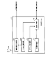
- FIG. 2 is a diagram showing the configuration of the GPS unit 3 according to the embodiment of the present invention.
- the GPS unit 3 includes an antenna 13, a reference signal generation unit 12, a reset control unit 14, an address management unit 16, a state management unit 18, and a communication I / F unit 15. .
- the antenna 13 receives a GPS signal from a GPS satellite. Based on the time information included in the received GPS signal, the reference signal generation unit 12 generates a reference signal that is a timing signal at a constant period and transmits the reference signal to the plurality of radio base stations 2.
- the address management unit 16 assigns a private IP address to each of its own device (GPS unit 3) and the plurality of wireless base stations 2.
- the address management unit 16 holds and manages the assigned private IP address, and notifies the set private IP addresses to the plurality of radio base stations 2 through the communication I / F unit 15.
- the state management unit 18 transmits its own state information according to a unique protocol every time a certain transmission cycle elapses.
- the state management unit 18 confirms that the reference signal is enabled for the plurality of radio base stations 2 when the reference signal can be supplied as a result of the acquisition of the signal from the GPS satellite.
- Information to be transmitted is transmitted according to a unique protocol.
- the state management unit 18 transmits state information indicating that the own device is in a normal state to the plurality of radio base stations 2 according to a unique protocol.
- the state management unit 18 is in a holdover state in which the own device is a kind of abnormal state with respect to the plurality of radio base stations 2 when a holdover state in which a signal from a GPS satellite cannot be captured. Is transmitted in accordance with a unique protocol.
- the reset control unit 14 When the reset control unit 14 receives a reset command transmitted in accordance with a unique protocol, the reset control unit 14 resets its own device. If the reset control unit 14 receives a new reset command while executing the reset, the reset control unit 14 rejects the reset command.
- the communication I / F unit 15 exchanges information with the radio base station 2 in accordance with a unique protocol using a private IP address.
- FIG. 3 is a diagram showing the configuration of the radio base station according to the embodiment of the present invention.
- this radio base station 2 includes antennas 28 and 29, a transmission / reception circuit 21, a PLL circuit 23, a first communication I / F unit 24, and a second communication I / F unit 25.
- the antennas 28 and 29 receive radio signals from the radio terminals and transmit radio signals to the radio terminals.
- the PLL circuit 23 performs feedback control based on the reference signal periodically transmitted from the GPS unit 3, and generates a synchronization signal synchronized with the phase of the reference signal.
- the transmission / reception circuit 21 receives signals from the wireless terminals output from the antennas 28 and 29, and transmits signals to the wireless terminals output through the antennas 28 and 29.
- the transmission / reception circuit 21 includes, for example, an encoding circuit, a modulation circuit, a decoding circuit, a demodulation circuit, and a MIMO (Multi In Multi Output) signal processing unit.
- the transmission / reception circuit 21 performs transmission / reception processing according to the synchronization signal output from the PLL circuit 23.
- the first communication I / F unit 24 exchanges information with the GPS unit 3 according to a unique protocol using a private IP address.
- the second communication I / F unit 25 exchanges information with the EMS 6 according to SNMP which is a standard protocol using a global IP address.
- SNMP is a protocol for monitoring and controlling a communication device connected to a TCP / IP (Transmission Control Protocol / Internet Protocol) network via the network.
- the address management unit 27 receives the private IP address of the GPS unit 3 and the private IP address of the own device (wireless base station) transmitted from the GPS unit 3, and holds and manages the received private IP address.
- the address management unit 27 further manages the global IP address of the own device and the EMS 6.
- the cycle timer 31 notifies the GPS state management unit 26 that the transmission cycle has passed every time the transmission cycle of the status information from the GPS unit 3 has passed.
- the GPS state management unit 26 receives information indicating that the reference signal transmitted from the GPS unit 3 is enabled according to a unique protocol.
- the GPS state management unit 26 When the GPS state management unit 26 receives state information indicating that the GPS unit 3 is in a normal state transmitted from the GPS unit 3 according to a unique protocol, the GPS state management unit 26 indicates to the EMS 6 that the GPS unit 3 is in a normal state.
- the status information is transmitted according to SNMP as the status information of the GPS receiver mounted on the device itself.
- the GPS state management unit 26 When the GPS state management unit 26 receives state information indicating that the GPS unit 3 transmitted from the GPS unit 3 is in a holdover state, which is a kind of abnormal state, according to the original protocol, the GPS unit 3 The state information indicating the holdover state is transmitted according to SNMP as the state information of the GPS receiver mounted on the own device.
- the GPS state management unit 26 When the GPS state management unit 26 receives a command for resetting the GSP receiver mounted on its own device transmitted from the EMS 6 according to SNMP, the GPS state management unit 26 transmits a reset command to the GPS unit 3 according to a unique protocol.
- the GPS status management unit 26 When the GPS status management unit 26 has received notification from the cycle timer 31 that the transmission cycle of the status information has elapsed, if the status information has not been received from the GPS unit 3, the GPS status management unit 26 notifies the EMS 6 of the GPS unit 3. Is transmitted in accordance with SNMP as the status information of the GPS receiver mounted on its own device.
- the power control unit 22 When the power control unit 22 receives a reset command from the EMS 6, the power control unit 22 reduces the transmission power of the radio signal. As a result, the area to be covered is narrowed so that it does not interfere with signals from other radio base stations and radio terminals as much as possible.
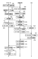
- FIG. 4 is a diagram illustrating an operation example of the GPS unit 3, the radio base station 2, and the EMS 6 according to the embodiment of the present invention.
- the operation of the radio base station 2 represents one of the plurality of radio base stations 2 as a representative.
- the address management unit 16 of the GPS unit 3 gives a private IP address to each of its own device (GPS unit 3) and the plurality of wireless base stations 2.
- the address management unit 16 holds and manages the assigned private IP address.
- the address management unit 16 notifies the plurality of wireless base stations 2 of the set private IP address of the own device and the private IP address of the wireless base station 2 through the communication I / F unit 15 (step S101). .
- the address management unit 27 of the radio base station 2 receives the private IP address of the GPS unit 3 and the private IP address of the own device (radio base station 2) through the first communication I / F unit 24, and receives it.
- the held private IP address is held and managed (step S102).
- the state management unit 18 transmits a plurality of radios through the communication I / F unit 15.
- Information indicating that the reference signal is enabled is transmitted to the base station 2 according to a unique protocol (step S103).
- the GPS state management unit 26 of the radio base station 2 receives information indicating that the reference signal transmitted according to the unique protocol is enabled through the first communication I / F unit 24 (step S104).
- the reference signal generation unit 12 of the GPS unit 3 starts generating the reference signal and transmits the generated reference signal to the plurality of radio base stations 2 (step S105).
- the PLL circuit 23 of the radio base station 2 receives the reference signal and generates a synchronization signal synchronized with the phase of the reference signal. Thereby, the transmission / reception circuit 21 operates in accordance with the synchronization signal output from the PLL circuit 23 (step S106).
- the state management unit 18 of the GPS unit 3 confirms that the own device is in a normal state with respect to the plurality of radio base stations 2 through the communication I / F unit 15 when the own device state is normal.
- the state information to be represented is transmitted according to a unique protocol at a constant cycle (step S107).
- the GPS state management unit 26 of the radio base station 2 receives the state information indicating that the GPS unit 3 transmitted in accordance with the unique protocol is in a normal state through the first communication I / F unit 24 (step). S108).
- the GPS state management unit 26 of the wireless base station 2 is loaded with its own state information indicating that the GPS unit 3 is in a normal state with respect to the EMS 6 through the second communication I / F unit 25.
- the GPS receiver status information is transmitted according to SNMP (step S109).
- the EMS 6 receives state information indicating that the GPS receiver mounted on the radio base station 2 transmitted according to SNMP is in a normal state (step S110).
- the state management unit 18 of the GPS unit 3 receives a plurality of wireless base stations 2 through the communication I / F unit 15 when a holdover state in which a signal from a GPS satellite cannot be captured (step S111). Then, state information indicating that the own apparatus is in the holdover state is transmitted according to the unique protocol (step S112).
- the GPS state management unit 26 of the wireless base station 2 receives state information indicating that the GPS unit 3 transmitted in accordance with the unique protocol is in the holdover state through the first communication I / F unit 24 ( Step S113).
- the GPS state management unit 26 of the radio base station 2 mounts status information indicating that the GPS unit 3 is in a holdover state on the EMS 6 via the second communication I / F unit 25 in its own device.
- the status information of the received GPS receiver is transmitted according to SNMP (step S114).
- the EMS 6 receives state information indicating that the GPS receiver mounted on the radio base station 2 transmitted according to SNMP is in the holdover state (step S115).
- the EMS 6 transmits a command for resetting the GPS receiver to the wireless base station 2 that has transmitted the state information indicating that the GPS receiver is in the holdover state according to SNMP (step S116).
- the GPS state management unit 26 of the radio base station 2 receives a command to reset the GSP receiver transmitted according to SNMP through the second communication I / F unit 25 (step S117).
- the GPS state management unit 26 of the radio base station 2 transmits a reset command to the GPS unit 3 through the first communication I / F unit 24 according to a unique protocol (step S118).
- the power control unit 22 of the radio base station 2 reduces the transmission power of the radio signal transmitted from the transmission / reception circuit 21 in accordance with an instruction from the GPS state management unit 26 (step S119).
- the reset control unit 14 of the GPS unit 3 receives the reset command transmitted according to the unique protocol through the communication I / F unit 15 (step S120).
- step S121 when the reset control unit 14 is not currently executing the reset (YES in step S121), the reset control unit 14 executes the reset (step S122). If the reset control unit 14 is currently executing a reset (NO in step S121), the reset control unit 14 ignores the received new reset command.
- FIG. 5 is a diagram illustrating another operation example of the GPS unit 3, the radio base station 2, and the EMS 6 according to the embodiment of this invention.
- the operation of the radio base station 2 represents one of the plurality of radio base stations 2 as a representative.
- the address management unit 16 of the GPS unit 3 gives a private IP address to each of its own device (GPS unit 3) and the plurality of wireless base stations 2.
- the address management unit 16 holds and manages the assigned private IP address.
- the address management unit 16 notifies the plurality of wireless base stations 2 of the set private IP address of the own device and the private IP address of the wireless base station 2 through the communication I / F unit 15 (step S201). .
- the address management unit 27 of the radio base station 2 receives the private IP address of the GPS unit 3 and the private IP address of the own device (radio base station 2) through the first communication I / F unit 24, and receives it.
- the held private IP address is held and managed (step S202).
- the state management unit 18 transmits a plurality of radios through the communication I / F unit 15.
- Information indicating that the reference signal is enabled is transmitted to the base station 2 according to a unique protocol (step S203).
- the GPS state management unit 26 of the radio base station 2 receives information indicating that the reference signal transmitted according to the unique protocol is enabled through the first communication I / F unit 24 (step S204).
- the reference signal generator 12 of the GPS unit 3 starts generating the reference signal and transmits the generated reference signal to the plurality of radio base stations 2 (step S205).
- the PLL circuit 23 of the radio base station 2 receives the reference signal and generates a synchronization signal synchronized with the phase of the reference signal. Thereby, the transmission / reception circuit 21 operates in accordance with the synchronization signal output from the PLL circuit 23 (step S206).
- the state management unit 18 of the GPS unit 3 confirms that the own device is in a normal state with respect to the plurality of radio base stations 2 through the communication I / F unit 15 when the own device state is normal.
- the state information to be represented is transmitted at a constant cycle according to the unique protocol (step S207).
- the GPS state management unit 26 of the radio base station 2 receives the state information indicating that the GPS unit 3 transmitted in accordance with the unique protocol is in a normal state through the first communication I / F unit 24 (step). S208).
- the GPS state management unit 26 of the wireless base station 2 is loaded with its own state information indicating that the GPS unit 3 is in a normal state with respect to the EMS 6 through the second communication I / F unit 25.
- the state information of the GPS receiver is transmitted according to SNMP (step S209).
- the EMS 6 receives state information indicating that the GPS receiver mounted on the wireless base station 2 transmitted according to SNMP is in a normal state (step S110).
- the GPS state management unit 26 of the wireless base station 2 transmits the state information transmission cycle from the cycle timer 31. Is received, and it is detected that the status information has not been received within the status information transmission cycle since the previous status information was received (step S212).
- the GPS status management unit 26 of the radio base station 2 mounts status information indicating that the GPS unit 3 is in an abnormal synchronization state with respect to the EMS 6 through the second communication I / F unit 25 in its own device.
- the status information of the received GPS receiver is transmitted according to SNMP (step S213).
- the EMS 6 receives state information indicating that the GPS receiver mounted on the wireless base station 2 transmitted according to SNMP is in a synchronization abnormal state (step S214).
- the EMS 6 transmits a command for resetting the GPS receiver to the wireless base station 2 that has transmitted the state information indicating that the GPS receiver is in an abnormal synchronization state according to SNMP (step S215).
- the GPS state management unit 26 of the radio base station 2 receives a command to reset the GSP receiver transmitted according to the SNMP through the second communication I / F unit 25 (step S216).
- the power control unit 22 of the radio base station 2 reduces the transmission power of the radio signal transmitted from the transmission / reception circuit 21 in accordance with an instruction from the GPS state management unit 26 (step S217).
- the GPS state management unit 26 of the radio base station 2 transmits a reset command to the GPS unit 3 through the first communication I / F unit 24 according to a unique protocol (step S218).
- the reset control unit 14 of the GPS unit 3 receives the reset command transmitted according to the unique protocol through the communication I / F unit 15 (step S219).
- step S220 when the reset control unit 14 is not currently executing the reset (YES in step S220), the reset control unit 14 executes the reset (step S221). If the reset control unit 14 is currently executing a reset (NO in step S220), the reset control unit 14 ignores the received new reset command.
- information for management and control is transmitted between a radio base station and a shared independent GPS unit using an independent protocol using a private IP address.
- the radio base station transmits information for managing and controlling the GPS unit to the EMS as information of a GPS receiver mounted on the radio base station.
- Radio base station that manages GPS units
- all of the radio base stations to which a single GPS unit supplies a reference signal have a private IP address.
- the status information and the reset command are transmitted according to the original protocol, the present invention is not limited to this.
- Only at least one of the plurality of radio base stations receiving the reference signal from the GPS unit may have a management function.
- At least one radio base station may have a private IP address and transmit state information and a reset command to and from the GPS unit according to a unique protocol.
Landscapes
- Engineering & Computer Science (AREA)
- Computer Networks & Wireless Communication (AREA)
- Signal Processing (AREA)
- Radar, Positioning & Navigation (AREA)
- Remote Sensing (AREA)
- Physics & Mathematics (AREA)
- General Physics & Mathematics (AREA)
- Mobile Radio Communication Systems (AREA)
Abstract
無線基地局(2)のPLL回路(23)は、GPSユニット(3)から送信される同期のための基準信号を受けて、基準信号に同期した同期信号を生成する。GPS状態管理部(26)は、EMS(6)へGPSユニット(3)の状態を表わす状態情報を自装置に搭載された基準信号を供給する装置の状態情報として標準規格の管理プロトコルであるSNMPに従って送信する。
Description
本発明は、無線基地局、基準信号供給装置、および無線基地局システムに関し、特に、複数の無線基地局が同期して動作するための構成および方法に関する。
従来から、セル方式の無線通信システムにおいて、隣接するセル間での送受信タイミングの同期化が行われている。より具体的には、あるセルにおける無線基地局とそのセルに含まれる端末装置との間の送受信タイミングを、隣接するセルにおける無線基地局とその隣接するセルに含まれる端末装置との間の送受信タイミングと一致させることで、隣接するセルの無線基地局と端末装置との間の干渉、および、端末装置間の干渉を抑制することができる。
このようなセル間での送受信タイミングの同期化を実現する一形態として、時刻情報を含む衛星からの信号を利用する構成が考えられる。現時点において、このような時刻情報を含む衛星からの信号の典型例としては、GPS(Global Positioning System)衛星からのGPS信号が知られている。すなわち、GPS衛星からのGPS信号を受信するためのGPS受信機を各無線基地局に設けて、各無線基地局が共通のGPS信号に基づいて、送受信タイミングを同期化するものである。
しかしながら、精度の高い同期信号を生成するGPSモジュールは、高価であるため、コストをより低減するために、複数の無線基地局が1つの独立したGPS受信機を共用する形態が考えられている。たとえば、特開2000-232688号公報(特許文献1)には、各基地局が、GPS受信機に結合されたシステムが開示されている。このシステムでは、GPS受信機がGPS衛星からのGPS信号を受信して、このGPS信号(基準信号)が複数の無線基地局での共通の時間的基準として用いられる。
一方、GPS受信機の状態を監視するために、EMS(Element Management System)が設置されている。従来のEMSは、無線基地局に搭載したGPS受信機から送信される正常または故障を表わす状態情報に基づき、監視および制御を行なうための管理サーバである。EMSは、標準規格の管理プロトコルであるSNMP(Simple Network Management Protocol)に基づいて、無線基地局を監視および制御している。
しかしながら、管理サーバが、直接、共用して使用する独立したGPS受信機を監視および制御する場合には、そのGPS受信機に対してグローバルIP(Internet Protocol)アドレスを付与しなければならない。なぜなら、EMSに共用の独立したGPS受信機を接続するためには、レイヤ3のスイッチを介して接続する必要があるからである。グローバルIPアドレスが不足している環境においては、同期のための基準信号を出力しているだけのGPS受信機に、グローバルIPアドレスを付与するのは好ましくない。
また、管理サーバが、直接、独立したGPS受信機を監視および制御する場合には、EMSに独立したGPS受信機を監視および制御するための機能を追加する必要がある。
それゆえに、本発明の目的は、共用の独立したGPS受信機にグローバルIPアドレスを付与することなく、かつEMSに共用の独立したGPS受信機を監視および制御するための機能を追加することなく、共用の独立したGPS受信機の状態を監視および制御することができる無線基地局、基準信号供給装置、および無線基地局システムを提供することである。
上記課題を解決するために、本発明の無線基地局は、基準信号供給装置から送信される同期のための基準信号を受けて、基準信号に同期した同期信号を生成する同期制御回路と、管理サーバへ、基準信号供給装置の状態を表わす状態情報を自装置に搭載された基準信号を供給する装置の状態情報として標準規格の管理プロトコルに従って送信する供給源状態管理部とを備える。
好ましくは、基準信号供給装置は、独自プロトコルに従って、所定の周期で自装置の状態を表わす状態情報を送信し、供給源状態管理部は、基準信号供給装置から、所定の周期内に状態情報を受信しない場合には、管理サーバへ基準信号供給装置が異常状態であることを表わす状態情報を自装置に搭載された基準信号を供給する装置の状態情報として標準規格の管理プロトコルに従って送信する。
好ましくは、基準信号供給装置は、独自プロトコルに従って、自装置の状態を表わす状態情報を送信し、供給源状態管理部は、基準信号供給装置から、独自プロトコルに従って伝送される基準信号供給装置が異常状態であることを表わす状態情報を受信した場合に、管理サーバへ基準信号供給装置が異常状態であることを表わす状態情報を自装置に搭載された基準信号を供給する装置の状態情報として標準規格の管理プロトコルに従って送信する。
好ましくは、管理サーバから、標準規格の管理プロトコルに従って伝送される自装置に搭載された基準信号を供給する装置のリセット命令を受信した場合に、基準信号供給装置へ、リセット命令を独自プロトコルに従って送信する供給源制御部をさらに備える。
好ましくは、リセット命令を受信した場合に、無線信号の送信電力を低下させる電力制御部をさらに備える。
好ましくは、管理サーバおよび無線基地局は、グローバルなIPアドレスが設定されており、標準規格の管理プロトコルは、SNMPである。
本発明の基準信号供給装置は、複数個の無線基地局に接続された基準信号供給装置であって、基準信号を生成して、複数個の無線基地局に供給する基準信号生成部と、独自プロトコルに従って、自装置の状態を表わす情報を少なくとも1つの無線基地局へ送信する状態管理部とを備える。
好ましくは、少なくとも1つの無線基地局および自装置に、プライベートIPアドレスを付与して、付与したプライベートIPアドレスを少なくとも1つの無線基地局に通知するアドレス管理部をさらに備える。
好ましくは、少なくとも1つの無線基地局から、独自プロトコルに従って伝送されるリセット命令を受信した場合に、自装置のリセットを実行するリセット制御部をさらに備える。
好ましくは、リセット制御部は、自装置のリセットを実行中に、少なくとも1つの無線基地局から、独自プロトコルに従って伝送される新たなリセットを命令を受信した場合には、新たなリセット命令を無視する。
本発明は、複数個の無線基地局と、複数個の無線基地局に同期のための基準信号を供給する基準信号供給装置とからなる無線基地局システムであって、基準信号供給装置は、基準信号を生成して、複数個の無線基地局に供給する基準信号生成部と、独自プロトコルに従って、自装置の状態を表わす情報を少なくとも1つの無線基地局へ送信する状態管理部とを備え、少なくとも1つの無線基地局は、基準信号供給装置から送信される同期のための基準信号を受けて、基準信号に同期した同期信号を生成する同期制御回路と、管理サーバへ、基準信号供給装置の状態を表わす状態情報を自装置に搭載された基準信号を供給する装置の状態情報として標準規格の管理プロトコルに従って送信する供給源状態管理部とを備える。
本発明によれば、共用の独立したGPS受信機にグローバルIPアドレスを付与することなく、かつEMSに共用の独立したGPS受信機を監視および制御するための機能を追加することなく、共用の独立したGPS受信機の状態を監視および制御することができる。
以下、本発明の実施形態について図面を参照して説明する。
(無線基地局システムの構成)
図1は、本発明の実施形態の無線基地局システムの構成を表わす図である。
(無線基地局システムの構成)
図1は、本発明の実施形態の無線基地局システムの構成を表わす図である。
図1を参照して、この無線基地局システム1は、複数のドメイン50A,50Bを含む。
ドメイン50Aは、1つのGPSユニット3Aと、GPSユニット3Aに通信ケーブル52A_1~52A_Nを介して接続された複数の無線基地局2A_1~2A_Nとを備える。
GPSユニット3Aから、ドメイン50A内の複数の無線基地局2A_1~2A_Nへ通信ケーブル52A_1~52A_Nを介して基準信号が供給される。これにより、ドメイン50A内の複数の無線基地局2A_1~2A_Nは、受信した基準信号に同期して動作する。
さらに、GPSユニット3Aは、レイヤ2スイッチ(L2SW)4Aとイーサーネット(登録商標)53Aで接続される。レイヤ2スイッチ(L2SW)4Aは、さらにイーサーネット51A_1~51A_Nを介して無線基地局2A_1~2A_Nに接続される。レイヤ2スイッチ(L2SW)4Aは、OSI(Open Systems Interconnection)参照モデルにおけるレイヤ2(データリンク層)に属するスイッチである。レイヤ2スイッチ(L2SW)4Aで接続されたGPSユニット3Aと、無線基地局2A_1~2A_Nとの間は、プライベートIPアドレスを用いた独自のプロトコルに従って管理および制御のための情報が伝送される。
同様に、ドメイン50Bは、1つのGPSユニット3Bと、GPSユニット3Bに通信ケーブル52B_1~52B_Nを介して接続された複数の無線基地局2B_1~2B_Nとを備える。
GPSユニット3Bから、ドメイン50B内の複数の無線基地局2B_1~2B_Nへ通信ケーブル52B_1~52B_Nを介して基準信号が供給される。これにより、ドメイン50B内の複数の無線基地局2B_1~2B_Nは、受信した基準信号に同期して動作する。
さらに、GPSユニット3Bは、レイヤ2スイッチ(L2SW)4Bとイーサネット(登録商標)53Bで接続される。レイヤ2スイッチ(L2SW)4Bは、さらにイーサーネット51B_1~51B_Nを介して無線基地局2B_1~2B_Nに接続される。レイヤ2スイッチ(L2SW)4Bは、OSI参照モデルにおけるレイヤ2(データリンク層)に属するスイッチである。レイヤ2スイッチ(L2SW)4Bで接続されたGPSユニット3Bと、無線基地局2B_1~2B_Nとの間は、プライベートIPアドレスを用いた独自のプロトコルに従って管理および制御のための情報が伝送される。
無線基地局2A_1~2A_N,2B_1~2B_Nは、さらに、イーサネット(登録商標)54A_1~54_N、54B_1~54_Nを介してレイヤ3スイッチ(L3SW)5と接続される。レイヤ3スイッチ(L3SW)5は、さらに、イーサネット(登録商標)55を介して管理サーバであるEMS6に接続される。
レイヤ3スイッチ(L3SW)5は、OSI参照モデルにおけるレイヤ3(ネットワーク層)に属するスイッチである。レイヤ3スイッチ(L3SW)5で接続されたEMS6と、無線基地局2A_1~2A_N,2B_1~2B_Nとの間は、グローパルIPアドレスを用いたSNMPに従って管理および制御のための情報が伝送される。
なお、以下の説明では、複数のGPSユニット3A、3Bを代表して、GPSユニット3と称し、複数の無線基地局2A_1~2A_N、2B_1~2B_Nを代表して、無線基地局2と称することもある。
(GPSユニット3の構成)
図2は、本発明の実施形態のGPSユニット3の構成を表わす図である。
図2は、本発明の実施形態のGPSユニット3の構成を表わす図である。
図2を参照して、GPSユニット3は、アンテナ13と、基準信号生成部12と、リセット制御部14と、アドレス管理部16と、状態管理部18と、通信I/F部15とを備える。
アンテナ13は、GPS衛星からのGPS信号を受信する。
基準信号生成部12は、受信したGPS信号に含まれる時刻情報に基づいて、タイミング信号である基準信号を一定の周期で生成して、複数の無線基地局2へ送信する。
基準信号生成部12は、受信したGPS信号に含まれる時刻情報に基づいて、タイミング信号である基準信号を一定の周期で生成して、複数の無線基地局2へ送信する。
アドレス管理部16は、自装置(GPSユニット3)および複数の無線基地局2の各々にプライベートIPアドレスを付与する。アドレス管理部16は、付与したプライベートIPアドレスを保持管理するとともに、通信I/F部15を通じて、複数の無線基地局2に対して、設定したプライベートIPアドレスを通知する。
状態管理部18は、一定の送信周期が経過するごとに、自装置の状態情報を独自プロトコルに従って送信する。
状態管理部18は、GPS衛星からの信号の捕捉が可能となった結果、基準信号の供給が可能となった場合に、複数の無線基地局2に対して、基準信号がイネーブルであることを表わす情報を独自プロトコルに従って送信する。
また、状態管理部18は、自装置の状態が正常の場合に、複数の無線基地局2に対して、自装置が正常状態であることを表わす状態情報を独自プロトコルに従って送信する。
また、状態管理部18は、GPS衛星からの信号が捕捉できないホールドオーバー状態となった場合に、複数の無線基地局2に対して、自装置が異常状態の一種であるホールドオーバー状態であることを表わす状態情報を独自プロトコルに従って送信する。
リセット制御部14は、独自プロトコルに従って伝送されるリセット命令を受信した場合に、自装置のリセットを実行する。リセット制御部14は、リセットを実行中に、新たなリセット命令を受信した場合には、そのリセット指示を拒絶する。
通信I/F部15は、プライベートIPアドレスを用いた独自プロトコルに従って、無線基地局2との間で情報をやりとりする。
(無線基地局の構成)
図3は、本発明の実施形態の無線基地局の構成を表わす図である。
図3は、本発明の実施形態の無線基地局の構成を表わす図である。
図3を参照して、この無線基地局2は、アンテナ28,29と、送受信回路21と、PLL回路23と、第1の通信I/F部24と、第2の通信I/F部25と、アドレス管理部27と、GPS状態管理部26と、電力制御部22と、周期タイマ31とを備える。
アンテナ28,29は、無線端末からの無線信号を受信し、無線端末への無線信号を送信する。
PLL回路23は、GPSユニット3から周期的に送信される基準信号を元にフィードバック制御を加えて、基準信号の位相に同期した同期信号を生成する。
送受信回路21は、アンテナ28,29から出力される無線端末からの信号を受信処理し、アンテナ28,29を通じて出力する無線端末への信号を送信処理する。送受信回路21は、たとえば、符号化回路、変調回路、復号回路、復調回路、およびMIMO(Multi In Multi Output)信号処理部などを含む。送受信回路21は、PLL回路23から出力される同期信号に従って、送受信処理を行なう。
第1の通信I/F部24は、プライベートIPアドレスを用いた独自プロトコルに従って、GPSユニット3との間で情報をやりとりする。
第2の通信I/F部25は、グローバルIPアドレスを用いた標準規格のプロトコルであるSNMPに従って、EMS6との間で情報をやりとりする。SNMPは、TCP/IP(Transmission Control Protocol/Internet Protocol)のネットワークに接続された通信機器をネットワーク経由で監視および制御するためのプロトコルである。
アドレス管理部27は、GPSユニット3から送信されるGPSユニット3のプライベートIPアドレスおよび自装置(無線基地局)のプライベートIPアドレスを受信し、受信したプライベートIPアドレスを保持管理する。アドレス管理部27は、さらに自装置およびEMS6のグローバルIPアドレスを管理する。
周期タイマ31は、GPSユニット3からの状態情報の送信周期が経過するごとに、GPS状態管理部26に送信周期が経過したことを通知する。
GPS状態管理部26は、独自プロトコルに従ってGPSユニット3から伝送される基準信号がイネーブルであることを表わす情報を受信する。
GPS状態管理部26は、独自プロトコルに従ってGPSユニット3から伝送されるGPSユニット3が正常状態であることを表わす状態情報を受信すると、EMS6に対して、GPSユニット3が正常状態であることを表わす状態情報を自装置に搭載されたGPS受信機の状態情報としてSNMPに従って送信する。
GPS状態管理部26は、独自プロトコルに従ってGPSユニット3から伝送されるGPSユニット3が異常状態の一種であるホールドオーバー状態であることを表わす状態情報を受信すると、EMS6に対して、GPSユニット3がホールドオーバー状態であることを表わす状態情報を自装置に搭載されたGPS受信機の状態情報としてSNMPに従って送信する。
GPS状態管理部26は、SNMPに従ってEMS6から伝送される自装置に搭載されたGSP受信機をリセットする命令を受信すると、GPSユニット3に対して、リセット命令を独自プロトコルに従って送信する。
GPS状態管理部26は、周期タイマ31から状態情報の送信周期が経過したことの通知を受けた時点で、GPSユニット3から状態情報を受信してない場合に、EMS6に対して、GPSユニット3が異常状態の一種である同期異常状態であることを表わす状態情報を自装置に搭載されたGPS受信機の状態情報としてSNMPに従って送信する。
電力制御部22は、EMS6からリセット命令を受信した場合に、無線信号の送信電力を低下させる。これにより、カバーするエリアを狭くして、他の無線基地局および無線端末からの信号とできるだけ干渉しないようにする。
(動作例1)
図4は、本発明の実施形態のGPSユニット3と、無線基地局2と、EMS6の動作例を表わす図である。図4において、無線基地局2の動作は、複数の無線基地局2のうちのいずれか1つの動作を代表して表わしたものである。
図4は、本発明の実施形態のGPSユニット3と、無線基地局2と、EMS6の動作例を表わす図である。図4において、無線基地局2の動作は、複数の無線基地局2のうちのいずれか1つの動作を代表して表わしたものである。
まず、GPSユニット3のアドレス管理部16は、自装置(GPSユニット3)および複数の無線基地局2の各々にプライベートIPアドレスを付与する。アドレス管理部16は、付与したプライベートIPアドレスを保持管理する。アドレス管理部16は、通信I/F部15を通じて、複数の無線基地局2に対して、設定した自装置のプライベートIPアドレスと、その無線基地局2のプライベートIPアドレスを通知する(ステップS101)。
次に、無線基地局2のアドレス管理部27は、第1の通信I/F部24を通じて、GPSユニット3のプライベートIPアドレスおよび自装置(無線基地局2)のプライベートIPアドレスを受信し、受信したプライベートIPアドレスを保持管理する(ステップS102)。
次に、GPSユニット3の状態管理部18は、GPS衛星からの信号の捕捉が可能となった結果、基準信号の供給が可能となった場合に、通信I/F部15を通じて、複数の無線基地局2に対して、基準信号がイネーブルであることを表わす情報を独自プロトコルに従って送信する(ステップS103)。
次に、無線基地局2のGPS状態管理部26は、第1の通信I/F部24を通じて、独自プロトコルに従って伝送される基準信号がイネーブルであることを表わす情報を受信する(ステップS104)。
次に、GPSユニット3の基準信号生成部12は、基準信号の生成を開始して、生成した基準信号を複数の無線基地局2へ送信する(ステップS105)。
次に、無線基地局2のPLL回路23は、基準信号を受信して、基準信号の位相に同期した同期信号を生成する。これにより、送受信回路21は、PLL回路23から出力される同期信号に従って、動作する(ステップS106)。
次に、GPSユニット3の状態管理部18は、自装置の状態が正常の場合に、通信I/F部15を通じて、複数の無線基地局2に対して、自装置が正常状態であることを表わす状態情報を一定の周期で独自プロトコルに従って送信する(ステップS107)。
次に、無線基地局2のGPS状態管理部26は、第1の通信I/F部24を通じて、独自プロトコルに従って伝送されるGPSユニット3が正常状態であることを表わす状態情報を受信する(ステップS108)。
次に、無線基地局2のGPS状態管理部26は、第2の通信I/F部25を通じて、EMS6に対して、GPSユニット3が正常状態であることを表わす状態情報を自装置に搭載されたGPS受信機の状態情報としてSNMPに従って送信する(ステップS109)。
次に、EMS6は、SNMPに従って伝送された無線基地局2に搭載されたGPS受信機が正常状態であることを表わす状態情報を受信する(ステップS110)。
次に、GPSユニット3の状態管理部18は、GPS衛星からの信号が捕捉できないホールドオーバー状態となった場合に(ステップS111)、通信I/F部15を通じて、複数の無線基地局2に対して、自装置がホールドオーバー状態であることを表わす状態情報を独自プロトコルに従って送信する(ステップS112)。
次に、無線基地局2のGPS状態管理部26は、第1の通信I/F部24を通じて、独自プロトコルに従って伝送されるGPSユニット3がホールドオーバー状態であることを表わす状態情報を受信する(ステップS113)。
次に、無線基地局2のGPS状態管理部26は、第2の通信I/F部25を通じて、EMS6に対して、GPSユニット3がホールドオーバー状態であることを表わす状態情報を自装置に搭載されたGPS受信機の状態情報としてSNMPに従って送信する(ステップS114)。
次に、EMS6は、SNMPに従って伝送された無線基地局2に搭載されたGPS受信機がホールドオーバー状態であることを表わす状態情報を受信する(ステップS115)。
次に、EMS6は、GPS受信機がホールドオーバー状態であることを表わす状態情報を送信した無線基地局2に対して、GPS受信機をリセットする命令をSNMPに従って、送信する(ステップS116)。
次に、無線基地局2のGPS状態管理部26は、第2の通信I/F部25を通じて、SNMPに従って伝送されるGSP受信機をリセットする命令を受信する(ステップS117)。
次に、無線基地局2のGPS状態管理部26は、第1の通信I/F部24を通じて、GPSユニット3に対して、リセット命令を独自プロトコルに従って送信する(ステップS118)。
次に、無線基地局2の電力制御部22は、GPS状態管理部26からの指示で、送受信回路21から送信する無線信号の送信電力を低下させる(ステップS119)。
次に、GPSユニット3のリセット制御部14は、通信I/F部15を通じて、独自プロトコルに従って伝送されるリセット命令を受信する(ステップS120)。
次に、リセット制御部14は、現在リセットを実行中でない場合に(ステップS121でYES)、リセットを実行する(ステップS122)。リセット制御部14は、現在リセットを実行中の場合には(ステップS121でNO)、受信した新たなリセット命令を無視する。
(動作例2)
図5は、本発明の実施形態のGPSユニット3と、無線基地局2と、EMS6の別の動作例を表わす図である。図5において、無線基地局2の動作は、複数の無線基地局2のうちのいずれか1つの動作を代表して表わしたものである。
図5は、本発明の実施形態のGPSユニット3と、無線基地局2と、EMS6の別の動作例を表わす図である。図5において、無線基地局2の動作は、複数の無線基地局2のうちのいずれか1つの動作を代表して表わしたものである。
まず、GPSユニット3のアドレス管理部16は、自装置(GPSユニット3)および複数の無線基地局2の各々にプライベートIPアドレスを付与する。アドレス管理部16は、付与したプライベートIPアドレスを保持管理する。アドレス管理部16は、通信I/F部15を通じて、複数の無線基地局2に対して、設定した自装置のプライベートIPアドレスと、その無線基地局2のプライベートIPアドレスを通知する(ステップS201)。
次に、無線基地局2のアドレス管理部27は、第1の通信I/F部24を通じて、GPSユニット3のプライベートIPアドレスおよび自装置(無線基地局2)のプライベートIPアドレスを受信し、受信したプライベートIPアドレスを保持管理する(ステップS202)。
次に、GPSユニット3の状態管理部18は、GPS衛星からの信号の捕捉が可能となった結果、基準信号の供給が可能となった場合に、通信I/F部15を通じて、複数の無線基地局2に対して、基準信号がイネーブルであることを表わす情報を独自プロトコルに従って送信する(ステップS203)。
次に、無線基地局2のGPS状態管理部26は、第1の通信I/F部24を通じて、独自プロトコルに従って伝送される基準信号がイネーブルであることを表わす情報を受信する(ステップS204)。
次に、GPSユニット3の基準信号生成部12は、基準信号の生成を開始して、生成した基準信号を複数の無線基地局2へ送信する(ステップS205)。
次に、無線基地局2のPLL回路23は、基準信号を受信して、基準信号の位相に同期した同期信号を生成する。これにより、送受信回路21は、PLL回路23から出力される同期信号に従って、動作する(ステップS206)。
次に、GPSユニット3の状態管理部18は、自装置の状態が正常の場合に、通信I/F部15を通じて、複数の無線基地局2に対して、自装置が正常状態であることを表わす状態情報を一定周期で独自プロトコルに従って送信する(ステップS207)。
次に、無線基地局2のGPS状態管理部26は、第1の通信I/F部24を通じて、独自プロトコルに従って伝送されるGPSユニット3が正常状態であることを表わす状態情報を受信する(ステップS208)。
次に、無線基地局2のGPS状態管理部26は、第2の通信I/F部25を通じて、EMS6に対して、GPSユニット3が正常状態であることを表わす状態情報を自装置に搭載されたGPS受信機の状態情報としてSNMPに従って送信する(ステップS209)。
次に、EMS6は、SNMPに従って伝送される無線基地局2に搭載されたGPS受信機が正常状態であることを表わす状態情報を受信する(ステップS110)。
次に、GPSユニット3で故障が発生したために、基準信号が送信できない状態となった場合に(ステップS211)、無線基地局2のGPS状態管理部26は、周期タイマ31から状態情報の送信周期が経過したことの通知を受け、前回状態情報を受信してから状態情報の送信周期内に状態情報が受信していないことを検出する(ステップS212)。
次に、無線基地局2のGPS状態管理部26は、第2の通信I/F部25を通じて、EMS6に対して、GPSユニット3が同期異常状態であることを表わす状態情報を自装置に搭載されたGPS受信機の状態情報としてSNMPに従って送信する(ステップS213)。
次に、EMS6は、SNMPに従って伝送される無線基地局2に搭載されたGPS受信機が同期異常状態であることを表わす状態情報を受信する(ステップS214)。
次に、EMS6は、GPS受信機が同期異常状態であることを表わす状態情報を送信した無線基地局2に対して、GPS受信機をリセットする命令をSNMPに従って、送信する(ステップS215)。
次に、無線基地局2のGPS状態管理部26は、第2の通信I/F部25を通じて、SNMPに従って伝送されるGSP受信機をリセットする命令を受信する(ステップS216)。
次に、無線基地局2の電力制御部22は、GPS状態管理部26からの指示で、送受信回路21から送信する無線信号の送信電力を低下させる(ステップS217)。
次に、無線基地局2のGPS状態管理部26は、第1の通信I/F部24を通じて、GPSユニット3に対して、リセット命令を独自プロトコルに従って送信する(ステップS218)。
次に、GPSユニット3のリセット制御部14は、通信I/F部15を通じて、独自プロトコルに従って伝送されるリセット命令を受信する(ステップS219)。
次に、リセット制御部14は、現在リセットを実行中でない場合に(ステップS220でYES)、リセットを実行する(ステップS221)。リセット制御部14は、現在リセットを実行中の場合には(ステップS220でNO)、受信した新たなリセット命令を無視する。
以上のように、本発明の実施形態によれば、無線基地局と共用の独立したGPSユニットとの間でプライベートIPアドレスを用いた独立したプロトコルで管理および制御のための情報を伝送する。無線基地局が、GPSユニットの管理および制御のための情報を自己に搭載したGPS受信機の情報としてEMSに伝送する。これにより、GPSユニットとEMSとの間で管理および制御のための情報を直接伝送する必要がないので、GPSユニットにグローバルIPアドレスを付与しなくてもよく、またEMSにGPSユニットを監視および制御するための機能を追加しなくてもよいようにすることができる。
(変形例)
本発明は、上記の実施形態に限定されるものではなく、たとえば以下のような変形例も含む。
本発明は、上記の実施形態に限定されるものではなく、たとえば以下のような変形例も含む。
(1) GPSユニットを管理する無線基地局
本発明の実施形態では、1つのGPSユニットが基準信号を供給している無線基地局のすべてがプライベートIPアドレスを有し、そのGPSユニットとの間で独自プロトコルに従って、状態情報およびリセット命令を伝送したが、これに限定するものではない。
本発明の実施形態では、1つのGPSユニットが基準信号を供給している無線基地局のすべてがプライベートIPアドレスを有し、そのGPSユニットとの間で独自プロトコルに従って、状態情報およびリセット命令を伝送したが、これに限定するものではない。
GPSユニットから基準信号を受けている複数の無線基地局のうちの少なくとも1つの無線基地局のみに管理機能を持たせることとしてよい。
すなわち、少なくとも1つの無線基地局がプライベートIPアドレスを有し、GPSユニットとの間で独自プロトコルに従って、状態情報およびリセット命令を伝送するようにしてもよい。
今回開示された実施の形態はすべての点で例示であって制限的なものではないと考えられるべきである。本発明の範囲は上記した説明ではなくて請求の範囲によって示され、請求の範囲と均等の意味および範囲内でのすべての変更が含まれることが意図される。
1 無線基地局システム、2,2A_1~2A_N,2B_1~2B_N 無線基地局、3,3A,3B GPSユニット、4A,4B レイヤ2スイッチ、5 レイヤ3スイッチ、6 EMS、12 基準信号生成部、13,28,29 アンテナ、14 リセット制御部、15 通信I/F部、16,27 アドレス管理部、18 状態管理部、21送受信回路、22 電力制御部、23 PLL回路、24 第1の通信I/F部、25 第2の通信I/F部、26 GPS状態管理部、31 周期タイマ、50A,50B ドメイン、51A_1~51A_N,51B_1~51B_N 通信ケーブル、52A_1~52A_N,52B_1~52B_N,53A,53B,54A_1~54A_N,54B_1~54B_N,55 イーサネット(登録商標)。
Claims (11)
- 基準信号供給装置から送信される同期のための基準信号を受けて、前記基準信号に同期した同期信号を生成する同期制御回路と、
管理サーバへ、前記基準信号供給装置の状態を表わす状態情報を自装置に搭載された基準信号を供給する装置の状態情報として標準規格の管理プロトコルに従って送信する供給源状態管理部とを備えた無線基地局。 - 前記基準信号供給装置は、独自プロトコルに従って、所定の周期で自装置の状態を表わす状態情報を送信し、
前記供給源状態管理部は、前記基準信号供給装置から、前記所定の周期内に状態情報を受信しない場合には、前記管理サーバへ前記基準信号供給装置が異常状態であることを表わす状態情報を前記自装置に搭載された基準信号を供給する装置の状態情報として前記標準規格の管理プロトコルに従って送信する、請求の範囲第1項に記載の無線基地局。 - 前記基準信号供給装置は、独自プロトコルに従って、自装置の状態を表わす状態情報を送信し、
前記供給源状態管理部は、前記基準信号供給装置から、独自プロトコルに従って伝送される前記基準信号供給装置が異常状態であることを表わす状態情報を受信した場合に、前記管理サーバへ前記基準信号供給装置が異常状態であることを表わす状態情報を前記自装置に搭載された基準信号を供給する装置の状態情報として前記標準規格の管理プロトコルに従って送信する、請求の範囲第1項に記載の無線基地局。 - 前記管理サーバから、前記標準規格の管理プロトコルに従って伝送される前記自装置に搭載された基準信号を供給する装置のリセット命令を受信した場合に、前記基準信号供給装置へ、リセット命令を独自プロトコルに従って送信する供給源制御部をさらに備えた、請求の範囲第1項に記載の無線基地局。
- 前記リセット命令を受信した場合に、無線信号の送信電力を低下させる電力制御部をさらに備えた、請求の範囲第4項に記載の無線基地局。
- 前記管理サーバおよび前記無線基地局は、グローバルなIPアドレスが設定されており、
前記標準規格の管理プロトコルは、SNMPである、請求の範囲第1項に記載の無線基地局。 - 複数個の無線基地局に接続された基準信号供給装置であって、
基準信号を生成して、複数個の無線基地局に供給する基準信号生成部と、
独自プロトコルに従って、自装置の状態を表わす情報を少なくとも1つの無線基地局へ送信する状態管理部とを備えた、基準信号供給装置。 - 前記少なくとも1つの無線基地局および自装置に、プライベートIPアドレスを付与して、前記付与したプライベートIPアドレスを前記少なくとも1つの無線基地局に通知するアドレス管理部をさらに備えた、請求の範囲第7項に記載の基準信号供給装置。
- 前記少なくとも1つの無線基地局から、独自プロトコルに従って伝送されるリセット命令を受信した場合に、自装置のリセットを実行するリセット制御部をさらに備えた、請求の範囲第8項に記載の基準信号供給装置。
- 前記リセット制御部は、自装置のリセットを実行中に、前記少なくとも1つの無線基地局から、前記独自プロトコルに従って伝送される新たなリセットを命令を受信した場合には、前記新たなリセット命令を無視する、請求の範囲第9項に記載の基準信号供給装置。
- 複数個の無線基地局と、前記複数個の無線基地局に同期のための基準信号を供給する基準信号供給装置とからなる無線基地局システムであって、
前記基準信号供給装置は、
基準信号を生成して、複数個の無線基地局に供給する基準信号生成部と、
独自プロトコルに従って、自装置の状態を表わす情報を少なくとも1つの無線基地局へ送信する状態管理部とを備え、
前記少なくとも1つの無線基地局は、
前記基準信号供給装置から送信される同期のための基準信号を受けて、前記基準信号に同期した同期信号を生成する同期制御回路と、
管理サーバへ、前記基準信号供給装置の状態を表わす状態情報を自装置に搭載された基準信号を供給する装置の状態情報として標準規格の管理プロトコルに従って送信する供給源状態管理部とを備えた、無線基地局システム。
Priority Applications (1)
| Application Number | Priority Date | Filing Date | Title |
|---|---|---|---|
| US13/498,701 US9131437B2 (en) | 2009-09-28 | 2010-09-17 | Wireless base station, reference signal supply device, and wireless base station system |
Applications Claiming Priority (2)
| Application Number | Priority Date | Filing Date | Title |
|---|---|---|---|
| JP2009223061A JP5391503B2 (ja) | 2009-09-28 | 2009-09-28 | 無線基地局、基準信号供給装置、無線基地局システム、および無線基地局システムの運用方法 |
| JP2009-223061 | 2009-09-28 |
Publications (1)
| Publication Number | Publication Date |
|---|---|
| WO2011037076A1 true WO2011037076A1 (ja) | 2011-03-31 |
Family
ID=43795823
Family Applications (1)
| Application Number | Title | Priority Date | Filing Date |
|---|---|---|---|
| PCT/JP2010/066124 Ceased WO2011037076A1 (ja) | 2009-09-28 | 2010-09-17 | 無線基地局、基準信号供給装置、および無線基地局システム |
Country Status (3)
| Country | Link |
|---|---|
| US (1) | US9131437B2 (ja) |
| JP (1) | JP5391503B2 (ja) |
| WO (1) | WO2011037076A1 (ja) |
Families Citing this family (3)
| Publication number | Priority date | Publication date | Assignee | Title |
|---|---|---|---|---|
| FI20126240L (fi) | 2012-11-26 | 2014-05-27 | Tellabs Oy | Satelliittivastaanotinmoduuli tietoliikennelaitteistoa varten |
| US9565645B1 (en) * | 2014-08-05 | 2017-02-07 | Sprint Communications Company L.P. | Method for a small cell to wirelessly connect to a grandmaster timing device |
| CN104394586B (zh) * | 2014-11-28 | 2018-04-27 | 广州杰赛科技股份有限公司 | 微型基站、时钟服务器同步方法和系统 |
Citations (3)
| Publication number | Priority date | Publication date | Assignee | Title |
|---|---|---|---|---|
| JP2002164837A (ja) * | 2000-11-27 | 2002-06-07 | Kyocera Corp | 移動通信システム及び基地局装置 |
| JP2004328751A (ja) * | 2003-04-25 | 2004-11-18 | Samsung Electronics Co Ltd | 基地局装置のための衛星クロック同期システム及びそれを利用した基地局システムの衛星クロック同期化方法 |
| WO2005051024A1 (ja) * | 2003-11-20 | 2005-06-02 | Nec Corporation | 私設網を利用した移動通信システム、中継ノード及び無線基地制御局 |
Family Cites Families (11)
| Publication number | Priority date | Publication date | Assignee | Title |
|---|---|---|---|---|
| US6332086B2 (en) * | 1997-04-07 | 2001-12-18 | Graham Avis | Discontinuous receive operation in a wireless terminal |
| JP4267092B2 (ja) * | 1998-07-07 | 2009-05-27 | 富士通株式会社 | 時刻同期方法 |
| US6678258B1 (en) | 1998-11-30 | 2004-01-13 | Motorola, Inc. | Method and apparatus for paging a communication unit in a packet data communication system |
| JP2002217809A (ja) * | 2001-01-12 | 2002-08-02 | Toshiba Corp | 無線通信システム |
| JP4474207B2 (ja) | 2004-06-10 | 2010-06-02 | 富士通株式会社 | ネットワーク管理システム、ネットワーク管理方法 |
| US7305240B2 (en) * | 2005-02-03 | 2007-12-04 | Intel Corporation | Method and system of network management software architectures for mobile broadband wireless networks |
| US7978845B2 (en) * | 2005-09-28 | 2011-07-12 | Panduit Corp. | Powered patch panel |
| KR100854921B1 (ko) * | 2008-02-18 | 2008-08-27 | 주식회사 하이텍씨앤아이 | 무선 원격 검침장치 및 그의 구동방법 |
| US8614975B2 (en) * | 2008-09-19 | 2013-12-24 | Qualcomm Incorporated | Synchronizing a base station in a wireless communication system |
| WO2010063127A1 (en) * | 2008-12-03 | 2010-06-10 | Nortel Networks Limited | Multiple redundant gnss synchronization system |
| WO2010099049A2 (en) * | 2009-02-24 | 2010-09-02 | Eamonn Gormley | Base station reference frequency and timing correction |
-
2009
- 2009-09-28 JP JP2009223061A patent/JP5391503B2/ja not_active Expired - Fee Related
-
2010
- 2010-09-17 WO PCT/JP2010/066124 patent/WO2011037076A1/ja not_active Ceased
- 2010-09-17 US US13/498,701 patent/US9131437B2/en not_active Expired - Fee Related
Patent Citations (3)
| Publication number | Priority date | Publication date | Assignee | Title |
|---|---|---|---|---|
| JP2002164837A (ja) * | 2000-11-27 | 2002-06-07 | Kyocera Corp | 移動通信システム及び基地局装置 |
| JP2004328751A (ja) * | 2003-04-25 | 2004-11-18 | Samsung Electronics Co Ltd | 基地局装置のための衛星クロック同期システム及びそれを利用した基地局システムの衛星クロック同期化方法 |
| WO2005051024A1 (ja) * | 2003-11-20 | 2005-06-02 | Nec Corporation | 私設網を利用した移動通信システム、中継ノード及び無線基地制御局 |
Non-Patent Citations (1)
| Title |
|---|
| NAOKI ICHIKAWA ET AL: "Network no Seimeisen o Sasaeru Kohinshitsu Clock-mo System no Jitsugen", NTT GIJUTSU JOURNAL, THE TELECOMMUNICATIONS ASSOCIATION, vol. 21, no. 3, 1 March 2009 (2009-03-01), pages 42 - 45 * |
Also Published As
| Publication number | Publication date |
|---|---|
| US20120243529A1 (en) | 2012-09-27 |
| US9131437B2 (en) | 2015-09-08 |
| JP2011071901A (ja) | 2011-04-07 |
| JP5391503B2 (ja) | 2014-01-15 |
Similar Documents
| Publication | Publication Date | Title |
|---|---|---|
| EP2688240B1 (en) | Method, system and device for switching and selecting clock source device | |
| JP6698702B2 (ja) | 無線ネットワークの低電力センサーノード動作 | |
| CN102932961A (zh) | 挂起无线网络中的传输 | |
| EP2781074A1 (en) | Communication protocol for energy-harvesting devices | |
| CN103095749A (zh) | 用于实现跨网段设备发现的方法和系统 | |
| CN112637945B (zh) | 一种工业互联网络时钟同步的方法和系统 | |
| JP2010263588A (ja) | 伝送装置及び伝送装置の休止方法 | |
| JP2022174205A (ja) | 無線センサシステムおよび通信制御方法 | |
| JP5391503B2 (ja) | 無線基地局、基準信号供給装置、無線基地局システム、および無線基地局システムの運用方法 | |
| EP3649808B1 (en) | Low power cellular base station | |
| US20050216578A1 (en) | Methods, devices and computer program products using a node affiliation protocol for monitoring and/or controlling networkable devices | |
| JP5316957B2 (ja) | 無線基地局、基地局システムおよび無線通信方法 | |
| JP2011024013A (ja) | 無線通信方法及び無線センサーネットワークシステム | |
| EP4254901A1 (en) | Information processing apparatus, information processing system, information processing method, and program | |
| EP4254884A1 (en) | Information processing apparatus, information processing method, and program | |
| Krammer et al. | A fault-tolerant Backbone for IEEE 802.15. 4 based Networks | |
| US20090210556A1 (en) | Time division address management device and time division routing information management device | |
| WO2019117764A1 (en) | Methods and apparatus for providing synchronization within a subnetwork comprising a plurality of nodes | |
| CN121967198A (zh) | 一种用于LoRa网关的多网络服务器并行通信方法及LoRa网关 | |
| JP2003131958A (ja) | 時刻同期を可能とする方法 | |
| JP2023124618A (ja) | 無線通信装置、無線通信プログラム、及び無線通信方法 | |
| CN114268979A (zh) | 一种网管终端北向接口的安全通信方法 | |
| WO2025053808A1 (en) | A clock synchronization method | |
| EP3348028A1 (en) | System and method for scalable and efficient deployment of wireless infrastructure nodes for multiple collocated wireless field device networks | |
| EP2707976A1 (en) | Time synchronisation in a communication network |
Legal Events
| Date | Code | Title | Description |
|---|---|---|---|
| 121 | Ep: the epo has been informed by wipo that ep was designated in this application |
Ref document number: 10818749 Country of ref document: EP Kind code of ref document: A1 |
|
| NENP | Non-entry into the national phase |
Ref country code: DE |
|
| WWE | Wipo information: entry into national phase |
Ref document number: 13498701 Country of ref document: US |
|
| 122 | Ep: pct application non-entry in european phase |
Ref document number: 10818749 Country of ref document: EP Kind code of ref document: A1 |