WO2011033604A1 - 決定木作成装置 - Google Patents
決定木作成装置 Download PDFInfo
- Publication number
- WO2011033604A1 WO2011033604A1 PCT/JP2009/066069 JP2009066069W WO2011033604A1 WO 2011033604 A1 WO2011033604 A1 WO 2011033604A1 JP 2009066069 W JP2009066069 W JP 2009066069W WO 2011033604 A1 WO2011033604 A1 WO 2011033604A1
- Authority
- WO
- WIPO (PCT)
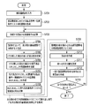
- Prior art keywords
- vertex
- unit
- component
- correspondence information
- condition
- Prior art date
- Legal status (The legal status is an assumption and is not a legal conclusion. Google has not performed a legal analysis and makes no representation as to the accuracy of the status listed.)
- Ceased
Links
Images



Classifications
-
- G—PHYSICS
- G06—COMPUTING OR CALCULATING; COUNTING
- G06Q—INFORMATION AND COMMUNICATION TECHNOLOGY [ICT] SPECIALLY ADAPTED FOR ADMINISTRATIVE, COMMERCIAL, FINANCIAL, MANAGERIAL OR SUPERVISORY PURPOSES; SYSTEMS OR METHODS SPECIALLY ADAPTED FOR ADMINISTRATIVE, COMMERCIAL, FINANCIAL, MANAGERIAL OR SUPERVISORY PURPOSES, NOT OTHERWISE PROVIDED FOR
- G06Q10/00—Administration; Management
- G06Q10/04—Forecasting or optimisation specially adapted for administrative or management purposes, e.g. linear programming or "cutting stock problem"
-
- G—PHYSICS
- G06—COMPUTING OR CALCULATING; COUNTING
- G06Q—INFORMATION AND COMMUNICATION TECHNOLOGY [ICT] SPECIALLY ADAPTED FOR ADMINISTRATIVE, COMMERCIAL, FINANCIAL, MANAGERIAL OR SUPERVISORY PURPOSES; SYSTEMS OR METHODS SPECIALLY ADAPTED FOR ADMINISTRATIVE, COMMERCIAL, FINANCIAL, MANAGERIAL OR SUPERVISORY PURPOSES, NOT OTHERWISE PROVIDED FOR
- G06Q10/00—Administration; Management
-
- G—PHYSICS
- G06—COMPUTING OR CALCULATING; COUNTING
- G06Q—INFORMATION AND COMMUNICATION TECHNOLOGY [ICT] SPECIALLY ADAPTED FOR ADMINISTRATIVE, COMMERCIAL, FINANCIAL, MANAGERIAL OR SUPERVISORY PURPOSES; SYSTEMS OR METHODS SPECIALLY ADAPTED FOR ADMINISTRATIVE, COMMERCIAL, FINANCIAL, MANAGERIAL OR SUPERVISORY PURPOSES, NOT OTHERWISE PROVIDED FOR
- G06Q10/00—Administration; Management
- G06Q10/10—Office automation; Time management
-
- G—PHYSICS
- G06—COMPUTING OR CALCULATING; COUNTING
- G06Q—INFORMATION AND COMMUNICATION TECHNOLOGY [ICT] SPECIALLY ADAPTED FOR ADMINISTRATIVE, COMMERCIAL, FINANCIAL, MANAGERIAL OR SUPERVISORY PURPOSES; SYSTEMS OR METHODS SPECIALLY ADAPTED FOR ADMINISTRATIVE, COMMERCIAL, FINANCIAL, MANAGERIAL OR SUPERVISORY PURPOSES, NOT OTHERWISE PROVIDED FOR
- G06Q99/00—Subject matter not provided for in other groups of this subclass
Definitions
- the present invention relates to a decision tree creation device that creates a decision tree for a part configuration table that is a correspondence table between part combinations and product numbers.
- a product such as a PC is configured by combining a plurality of component types (CPU, memory, HDD,). Each component type generally has a plurality of components (512 MB, 1024 MB, etc. for memory). In such product design, different product numbers are set according to the combination of parts. However, component combinations having the same product number may exist. Correspondence between component combinations and product numbers is generally described in a table format (referred to as a component configuration table). However, if the number of components and the number of components are large, the number of combinations increases and readability deteriorates.
- the component configuration table When the number of component combinations increases, the component configuration table also increases, and it takes time and effort to search where the component combination is listed when checking the product number for a specific component combination. If represented by a decision tree, the product number can be found by following the branch corresponding to the part from the root vertex, but even when represented by a decision tree, the depth of the tree generally increases as the number of vertices increases. It takes time to know the product number. That is, if the same contents are represented, a decision tree having a smaller number of vertices can easily know the product number.
- the present invention has been made in consideration of the above-described circumstances, and an object of the present invention is to provide a decision tree creating apparatus that generates a decision tree with a small number of vertices corresponding to a parts configuration table.
- a decision tree creation apparatus includes an input unit for inputting a correspondence table of component combinations and product numbers by a plurality of component types, and first correspondence information corresponding to the correspondence table.
- a correspondence information creating unit for creating first correspondence information including a reaching condition list that is a union of reaching conditions that are elements representing a plurality of component combinations and a product number, the correspondence table, and the first correspondence information
- the first condition creating unit that creates the first reaching condition of the first vertex of the decision tree from any one of the above, and all the component types that are unclassified at any second vertex that is an ancestor of the first vertex
- a division calculation unit that performs calculations to allocate names
- a second condition creating unit that creates a second reaching condition for each child vertex in accordance with the first reaching condition and the
- a determination unit for determining the classification component type and a first vertex of the component type determined by the determination unit are created, and a component name assigned to the branch from the first vertex to the child vertex is created from the calculation result of the division calculation unit And a vertex branch creating unit.
- the decision tree creation apparatus of the present invention it is possible to generate a decision tree with a small number of vertices corresponding to the parts configuration table.
- FIG. 8 is a diagram illustrating an example of a decision tree created up to step S712 in FIG.
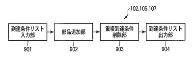
- FIG. 2 is a block diagram of a reduction processing apparatus that may be included in the product number-reaching condition list correspondence information creation unit, the component division calculation unit, and the pseudo child vertex related product number-reaching condition list correspondence information extraction unit of FIG.
- the number of vertices in the decision tree varies depending on the classification order of the component types. If the classification order is successfully determined, a small decision tree is constructed.
- An ID3 algorithm is known as a known technique. The ID3 algorithm calculates an expected value of the average information amount for the part type, and performs classification according to the part type that maximizes the expected value.
- the decision tree creation apparatus of this embodiment determines the component type to be classified by paying attention to the number of elements in the arrival condition list that can represent an arbitrary component combination without using the expected value of the average information amount.
- the decision tree creation apparatus of this embodiment is demonstrated with reference to FIG.
- the decision tree creation apparatus includes a part configuration table input unit 101, a product number-reaching condition list correspondence information creation unit 102, a created vertex arrival condition creation unit 103, a categorized part type provisional decision unit 104, and a part division calculation unit 105 , Pseudo child vertex reaching condition creating unit 106, pseudo child vertex related product number-reaching condition list correspondence information extracting unit 107, reaching condition list length calculating unit 108, classification part type determining unit 109, vertex / branch creating unit 110, decision tree An output unit 111 is included.
- the input unit 101 inputs a correspondence table (component configuration table) between component combinations and product numbers.
- a correspondence table component configuration table
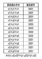
- FIGS there are parts configuration tables shown in FIGS.
- the part configuration table in FIG. 2 is an example of a part configuration table in which product numbers are individually defined for all part combinations of equipment, and there are equipments composed of part types X, Y, and Z. This is an example when it is assumed that x2 and x3 are classified into the component type X, the components y1 and y2 are classified into the component type Y, and the components z1 and z2 are classified into the component type Z.
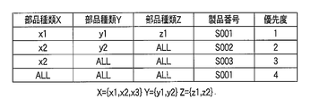
- the part configuration table in FIG. 3 is another description example (if-then-else format) of the part configuration table showing the same contents as in FIG.
- the priority is read in the order of 1 ⁇ 2 ⁇ ...
- the product number described in the line including the component combination is the product number corresponding to the component combination.
- each node of the decision tree is called a vertex, and a line connecting the vertices is called a branch.
- a vertex at the top layer of the decision tree is called a root vertex
- a vertex at the bottom layer of the decision tree is called a leaf vertex.
- X is a root vertex
- S001, S003, and S002 are leaf vertices.
- Y is a root vertex
- S001, S003, and S002 are leaf vertices.
- the decision tree shown in FIG. 4 represents the same content as the content of FIG. 2 or FIG.
- the decision tree shown in the left diagram of FIG. 4 is created. If the classification is performed in the order of component type Y ⁇ component type X, the decision tree shown in the right diagram of FIG. .
- the apex of the component type Z does not exist because it is not necessary to classify by the component type Z. For example, in the case of searching for the product number corresponding to the component combination (x3, y2, z1) and the decision tree shown in the left diagram of FIG. In the case of the decision tree shown in the right figure of 4, it is necessary to follow the branch twice. In other words, this is an example in which a decision tree having a smaller number of vertices (here, the decision tree shown in the left diagram of FIG. 4) can quickly check the product number.
- the correspondence information creation unit 102 creates product number-reaching condition list correspondence information (reaching condition list for each product number) corresponding to the input parts configuration table.
- the arrival condition list is a union of elements expressing a plurality of component combinations. Details will be described later with reference to FIG.
- the product number-reach condition list correspondence information will be described later with reference to FIG.
- a correspondence information input unit (not shown) that directly inputs product number-reach condition list correspondence information may be provided.
- the condition creation unit 103 creates a vertex arrival condition to be created.
- the condition creating unit 103 creates a component configuration table input by the input unit 101 or a component created by the correspondence information creating unit 102 for reaching conditions representing any combination of components. Created from the product number-reach condition list correspondence information corresponding to the configuration table. If the vertex to be created is not the root vertex of the decision tree, the arrival condition is calculated and created from the arrival condition of the parent vertex that has already been created and the part name attached to the branch (the result of the condition creation unit 106 may also be used) it can).
- the tentative determination unit 104 tentatively determines which component type to classify at the vertex to be created.
- the provisional determination unit 104 provisionally determines all the component types that are not classified at the vertex corresponding to the ancestor of the vertex to be created.
- the division calculation unit 105 determines how to assign a part name to a branch when it is assumed that classification is performed according to the classification part type determined by the provisional determination unit 104.
- the division calculation unit 105 tries to assign a plurality of part names to one branch as much as possible so as to minimize the number of branches, but always makes sure that all leaf vertices have a single product number.
- the part name is divided into branches. The part division method performed by the division calculation unit 105 will be described after the description of FIG.
- the condition creation unit 106 calculates and creates the arrival condition of the child vertex when it is assumed that the classification is performed according to the classification component type determined by the provisional determination unit 104.
- the correspondence information extraction unit 107 extracts the product number-reach condition list correspondence information related to the child vertex arrival conditions created by the condition creation unit 106 from the product number-reach condition list correspondence information created by the correspondence information creation unit 102. To do.
- the list length calculation unit 108 adds the number of elements of the arrival condition list that appears in the product number-arrival condition list correspondence information related to the child vertex arrival conditions extracted by the correspondence information extraction unit 107 for all child vertices.
- the determination unit 109 determines a component type temporarily determined by the temporary determination unit 104 that has the smallest number of elements calculated by the list length calculation unit 108 as a component type to be classified by the vertex to be created. To do.
- the creation unit 110 creates vertices of the component type determined by the determination unit 109, and creates a branch connecting the created vertex to the child vertex. For the part name given to the branch, the calculation performed by the division calculation unit 105 may be performed again, or the result calculated by the division calculation unit 105 may be used. When a child vertex corresponds to a unique product number, a child vertex (which becomes a leaf vertex) having that product number as a vertex is also created. If a branch for which a leaf vertex has not been created remains, the vertex to be created at that branch destination is set as the next vertex to be created and passed to the condition creation unit 103.
- the output unit 111 outputs (displays) the completed decision tree.
- the output unit 111 may acquire each time the creation unit 110 creates a vertex or a branch, and may display the progress in the middle of creation.
- the output unit 111 outputs the decision tree when the leaf vertices are created at all branch destinations.
- the arrival condition list is a data structure that can represent any combination of components.
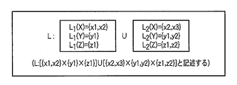
- the reaching condition list L shown in FIG. 5 has two elements, and the first element is a component combination represented by L 1 (X) ⁇ L 1 (Y) ⁇ L 1 (Z). Represents a component combination represented by L 2 (X) ⁇ L 2 (Y) ⁇ L 2 (Z).
- the component combination defined by the union of the component combinations represented by Specifically, (x1, y1, z1) (x2, y1, z1) (x2, y1, z2) (x2, y2, z1) (x2, y2, z2) (x3, y1, z1) (x3 y1, z2) (x3, y2, z1) (x3, y2, z2) of nine types of component combinations.
- (X2, y1, z1) is defined in either element of the reaching condition list, but there is no problem (considered as one component combination).
- a reaching condition list with one element is called a reaching condition.
- the arrival condition can be set at each vertex of the decision tree, and corresponds to a component combination that reaches the vertex. Also, the arrival condition that is the first element of the arrival condition list L in FIG.
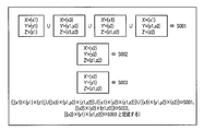
- the product number-reach condition list correspondence information is information (reach condition list for each product number) that represents the combination of parts corresponding to each product number in the reach condition list.
- the example of FIG. 6 is product number-reach condition list correspondence information representing the same content as that of FIG. 2 or FIG.
- the input unit 101 inputs a component configuration table.
- the input unit 101 inputs a component configuration table prepared by the user.
- the input unit 101 has three types, X, Y, and Z.
- the component type X includes components x1, x2, and x3
- the component type Y includes components y1 and y2
- the component type Z includes components z1 and z2. Get information that there is.
- the reaching condition L3 ′ [ ⁇ x2 ⁇ ⁇ ⁇ y1, y2 ⁇ ⁇ ⁇ z1, z2 ⁇ ] corresponds to the product number Y003, but L3 ′
- the arrival condition list L4 L4′-L3-L2-L1 is also calculated for the row of priority 4 in FIG.
- L4 ′ [ ⁇ x1, x2, x3 ⁇ ⁇ ⁇ y1, y2 ⁇ ⁇ ⁇ z1, z2 ⁇ ]).
- L4 [ ⁇ x3 ⁇ ⁇ ⁇ y1, y2 ⁇ ⁇ ⁇ z1, z2 ⁇ ] ⁇ [ ⁇ x1 ⁇ ⁇ ⁇ y2 ⁇ ⁇ ⁇ z1, z2 ⁇ ] ⁇ [ ⁇ x1 ⁇ ⁇ ⁇ y1, y2 ⁇ ⁇ ⁇ Z2 ⁇ ].
- the arrival condition lists (product number-arrival condition list correspondence information) for each product number are obtained by linking the arrival condition lists of the rows to which the same product number is assigned.
- the reach condition list L1 ⁇ L4 corresponds to the product number Y001
- L2 corresponds to Y002
- L3 corresponds to Y003.
- FIG. 6 is product number-reach condition list correspondence information obtained).
- Step S703 The condition creation unit 103 calculates the arrival condition of the vertex P to be created. Decision trees are created in order from the root vertex to the leaf vertex. That is, the vertex P to be created first is the root vertex. A reaching condition representing an arbitrary combination of parts that is a reaching condition of the root apex is created from the parts configuration table input in step S701 or the product number-reaching condition list correspondence information created in step S702. Since the vertex P is the root vertex, an arrival condition [ ⁇ x1, x2, x3 ⁇ ⁇ ⁇ y1, y2 ⁇ ⁇ ⁇ z1, z2 ⁇ ] that all component combinations reach is created. This reaching condition can be created because it is known in step S701 what kind of parts and parts exist.
- the vertex corresponding to the ancestor of the vertex P indicates a vertex located closer to the root vertex than the position of the vertex P in the decision tree.
- Step S705 When the division calculation unit 105 classifies the vertex P by the component type t selected in Step S704, the division calculation to be applied to the branch from the vertex P to the child vertex is calculated. In other words, the division calculation unit 105 calculates what part name should be used for creating the branch. If a result indicating that the component division is unnecessary is obtained, there is no meaning to divide by the component type t currently examined. In this case, the process returns to step S704 and the next component type is selected.
- t X, as shown in the left diagram of FIG. 4, a result that two branches, that is, a branch with x1 and x3 and a branch with x2 is generated from the root vertex P is calculated.
- the reason for assigning x2 to another branch is to make the leaf vertices correspond to a single serial number, and to assign x1 and x3 to the same branch is to minimize the number of branches (assign to different branches). But the leaf apex is a single serial number).
- the division calculation unit 105 tries to assign a plurality of part names to one branch as much as possible so that the number of branches is minimized.
- the part name is divided into branches so that all leaf vertices correspond to a single product number. A method of dividing the parts into branches will be described later.
- Step S706 The condition creation unit 106 calculates the arrival conditions (R Ct1 , R Ct2 ,%) Of the child vertices (C t1 , C t2 ,%) When the vertex P is classified by the component type t. When there are a plurality of product numbers corresponding to the component combinations, there are a plurality of child vertices. Child vertices are not vertices that are actually created at this point, so they are called pseudo child vertices. In this process, it is not necessary to actually create child vertices.
- the pseudo child vertex of the vertex P (denoted as a pseudo child vertex because no vertex is actually created) Only need to be calculated.
- the vertex P is a root vertex, and the arrival condition is [ ⁇ x1, x2, x3 ⁇ ⁇ ⁇ y1, y2 ⁇ ⁇ ⁇ z1, z2 ⁇ ] from the result of step S703.
- the reaching condition is [ ⁇ x1, x3 ⁇ ⁇ ⁇ y1, y2 ⁇ ⁇ ⁇ z1, z2 ⁇ ].
- the reaching condition of C X2 is [ ⁇ x2 ⁇ ⁇ ⁇ y1, y2 ⁇ ⁇ ⁇ z1, z2 ⁇ ].
- step S705 From the result of step S705, the a temporary child vertex C Y1 lead by branches attached to y1 from the apex P, temporary child vertex C Y2 is to be created which leads the branches attached to y2
- the reaching conditions are [ ⁇ x1, x2, x3 ⁇ ⁇ ⁇ y1 ⁇ ⁇ ⁇ z1, z2 ⁇ ] and [ ⁇ x1, x2, x3 ⁇ ⁇ ⁇ y2 ⁇ ⁇ ⁇ z1, z2 ⁇ ], respectively.
- Step S707 The correspondence information extraction unit 107 creates product number-reach condition list correspondence information (R Ct1 , R Ct2 ,...) Related to the reaching condition of the pseudo child vertex created in Step S706 in Step S702. Extract from product number-reach condition list.
- t X.
- the arrival condition [ ⁇ x1, x3 ⁇ ⁇ ⁇ y1, y2 ⁇ ⁇ ⁇ z1, z2 ⁇ ] of the pseudo child vertex C X1 does not include the component combination related to x2 from the root vertex having the arrival condition that all component combinations reach.
- the related product number-reach condition list correspondence information is obtained by deleting the information regarding the part x2 from the product number-reach condition list calculated in step S702 (in other words, x1 and x3 are related). What to do). That is, R CX1 : [ ⁇ x1 ⁇ ⁇ ⁇ y1 ⁇ ⁇ ⁇ z1 ⁇ ] ⁇ [ ⁇ x3 ⁇ ⁇ ⁇ y1, y2 ⁇ ⁇ ⁇ z1, z2 ⁇ ] ⁇ [ ⁇ x1 ⁇ ⁇ ⁇ y2 ⁇ ⁇ ⁇ z1, z2 ⁇ ] ⁇ [ ⁇ x1 ⁇ ⁇ ⁇ y1, y2 ⁇ ⁇ ⁇ z2 ⁇ ] ⁇ S001, ⁇ S002, ⁇ S003 is obtained.
- ⁇ represents a reaching condition list with 0 elements.
- R CX2 ⁇ : S001, [ ⁇ x2 ⁇ ⁇ ⁇ y2 ⁇ ⁇ ⁇ z1, z2 ⁇ ] ⁇ S002, [ ⁇ x2 ⁇ ⁇ ⁇ y1 ⁇ ⁇ ⁇ z1, z2 ⁇ ] ⁇ S003 is obtained.
- R CY1 [ ⁇ x1 ⁇ ⁇ ⁇ y1 ⁇ ⁇ ⁇ z1 ⁇ ] ⁇ [ ⁇ x3 ⁇ ⁇ ⁇ y1 ⁇ ⁇ ⁇ z1, z2 ⁇ ] ⁇ [ ⁇ x1 ⁇ ⁇ ⁇ y1 ⁇ ⁇ ⁇ z2 ⁇ ] ⁇ S001, ⁇ S002, [ ⁇ x2 ⁇ ⁇ ⁇ y1 ⁇ ⁇ ⁇ z1, z2 ⁇ ] ⁇ S003, R CY2 : [ ⁇ x3 ⁇ ⁇ ⁇ y2 ⁇ ⁇ ⁇ z1, z2 ⁇ ] ⁇ [ ⁇ X1 ⁇ ⁇ ⁇ y2 ⁇ ⁇ ⁇ z1, z2 ⁇ ] ⁇ [ ⁇ x1 ⁇ ⁇ ⁇ y2 ⁇ ⁇ ⁇ z2 ⁇ ] ⁇ S001, [ ⁇ x2 ⁇ ⁇ ⁇ y2 ⁇ ⁇ ⁇ z1, z2 ⁇ ] ⁇ S002, ⁇ ⁇ S003 is obtained.
- Step S708 The list length calculation unit 108 adds the number of elements of the reaching condition list appearing in the product number-arrival condition list correspondence information calculated in step S707 for each component type t (
- 6.
- t Y
- is added to obtain
- 8.
- Step S709 The determination unit 109 determines the component type with the smallest number of elements (
- Step S710 The creation unit 110 creates vertices P classified by the component type X determined in step S709.
- Step S711 The creation unit 110 creates a branch from the vertex P to the child vertex.
- the part name (part division) given to the branch to the child vertex reuses the result of step S705.
- Step S712 The creation unit 110 creates a leaf vertex corresponding to a single production number.
- Product Number arrival condition of the child vertex C X1 connected by branches from vertex P component x1 and x3 is attached is relevant - arrival condition list corresponding information R CX1 (reuse the result of step S707)
- child vertex C X1 is a single Since it can be seen that it corresponds to one product number S001 (the product number is not the product number S001 because the number of elements in the reaching condition list corresponding to S002 and S003 is 0), the leaf apex of the product number S001 as C X1 Create The child vertex C X2 connected from the vertex P by the branch to which the part x2 is attached cannot be classified into a single product number from R CX2 , so a leaf vertex is not created yet.
- FIG. 8 shows a decision tree created by the processing so far. If the progress of the decision tree configuration is also displayed, the decision tree shown in FIG. 8 is transferred to
- Step S713 The creation unit 110 checks whether the branch destinations of all vertices have become leaf vertices (vertices representing product numbers), and outputs a decision tree if leaf vertices have been created at the branch destinations of all vertices. The data is output to the unit 111 and output. On the other hand, if there is still a branch tip for which no leaf vertex has been created (in this example, the vertex corresponding to C X2 in step S712), the vertex attached to that branch tip is the vertex P to be created next, and step S703 is executed. Return to.
- Step S703 2nd The condition creation unit 103 calculates the arrival condition of the vertex P to be created. Now, since the vertex P is a child vertex connected by a branch to which the part x2 is attached from the parent vertex having the arrival condition [ ⁇ x1, x2, x3 ⁇ ⁇ ⁇ y1, y2 ⁇ ⁇ ⁇ z1, z2 ⁇ ], the arrival of the vertex P The condition is [ ⁇ x2 ⁇ ⁇ ⁇ y1, y2 ⁇ ⁇ ⁇ z1, z2 ⁇ ] (actually, since this is calculated once in step S706, this result is reused).
- Step S704 2nd Since the component types Y and Z are unclassified at the vertex P, the provisional determination unit 104 selects Y and Z as the classified component types t.
- Step S705 2nd to Step S709 2nd The division calculation unit 105 calculates the component division into branches when classified by the component type t.
- t Y
- the result is that two branches, a branch with y1 and a branch with y2, need to be created.
- t Z
- z1 and A result is obtained that one branch with z2 is sufficient (the classification is not necessary for the component type Z).
- the component type to be classified at the vertex P is determined as Y.
- Steps S706 to S709 are unnecessary if only the part type to be classified at the vertex P is determined, but in order to check whether the child vertex of the vertex P corresponds to a single product number, the reaching condition of the child vertex, The product number-reach condition list correspondence information related to the child vertex is calculated (steps S706 and S707).
- Step S710 2nd time The creation unit 110 creates a vertex P to be classified by the component type Y as a child vertex of the branch to which the component x2 is attached from the root vertex (parent vertex of the vertex P).
- Step S711 2nd The creation unit 110 creates a branch from the vertex P to the child vertex.
- the part attached to the branch reuses the result of step S705 (second time).
- Step S712 2nd The creation unit 110 creates leaf vertices corresponding to a single production number. This time, all the child vertices correspond to a single serial number, and as a result, the decision tree shown in the left diagram of FIG. 4 is created. Up to this point, leaf vertices have been created at all branches.
- Step S713 2nd The creation unit 110 confirms that leaf vertices have been created at all branch points. That is, the creation unit 110 confirms that the decision tree has been completed. The creation unit 110 passes the decision tree to the output unit 111 and displays it.
- step S705 a method of dividing a part into branches performed by the division calculation unit 105 in step S705 will be described.
- This method tries to assign multiple part names to one branch as much as possible so that the number of branches is minimized, but always make sure that all leaf vertices have a single product number.
- the branch with x1 and x3 and the branch with x2 are created from the root vertex P.
- the procedure until the result is output will be described.
- the arrival condition of the root vertex P has already been calculated as [ ⁇ x1, x2, x3 ⁇ ⁇ ⁇ y1, y2 ⁇ ⁇ ⁇ z1, z2 ⁇ ].
- product number-reach condition list correspondence information Rx related to the reach condition of its child vertex is calculated (similar to step S707 in FIG. 7). Can be calculated by the following method).
- R x1 [ ⁇ x1 ⁇ ⁇ ⁇ y1 ⁇ ⁇ ⁇ z1 ⁇ ] ⁇ [ ⁇ x1 ⁇ ⁇ ⁇ y2 ⁇ ⁇ ⁇ z1, z2 ⁇ ] ⁇ [ ⁇ x1 ⁇ ⁇ ⁇ y1, y2 ⁇ ⁇ ⁇ z2 ⁇ ] ⁇ S001 , ⁇ S002, ⁇ S003, R x2 : ⁇ S001, [ ⁇ x2 ⁇ ⁇ ⁇ y2 ⁇ ⁇ ⁇ z1, z2 ⁇ ] ⁇ S002, [ ⁇ x2 ⁇ ⁇ ⁇ y1 ⁇ ⁇ ⁇ z1, z2 ⁇ ] ⁇ S003, R x3 : [ ⁇ x3 ⁇ ⁇ ⁇ y1, y2 ⁇ ⁇ ⁇ z1, z2 ⁇ ] ⁇ S001, ⁇ S002, ⁇ S003 Product number-reach condition list correspondence information is obtained.
- L (x, s) represents a reaching condition list corresponding to the product number s in Rx.
- L (x2, S002) is [ ⁇ x2 ⁇ ⁇ ⁇ y2 ⁇ ⁇ ⁇ z1, z2 ⁇ ].
- the division calculation unit 105 determines whether or not the two parts c1 and c2 must be attached to different branches using the following determination method.
- the arrival condition list is a data structure that can represent any combination of parts, but there is no one-to-one correspondence between the combination of parts and the arrival condition list (a plurality of arrival condition lists that represent the same combination of parts exists).
- the arrival condition list represents the same content, a smaller number of elements (reach conditions) makes it easier to construct a decision tree with a smaller number of vertices, and a memory area required for calculation time and calculation This is also advantageous. Therefore, in the correspondence information creation unit 102, the division calculation unit 105, and the correspondence information extraction unit 107 that perform operations related to the arrival condition list, a process (contraction process) that shortens the number of elements (also referred to as length) of the arrival condition list as much as possible. ) Is desirable.
- FIG. 9 is a block diagram of an apparatus that performs reduction processing.
- This device includes a reaching condition list input unit 901, a component addition unit 902, a duplicate reaching condition deletion unit 903, and a reaching condition list output unit 904.
- the reaching condition list L [ ⁇ x1 ⁇ ⁇ ⁇ y1 ⁇ ⁇ ⁇ z1 ⁇ ] ⁇ [ ⁇ x3 ⁇ ⁇ ⁇ y1, y2 ⁇ ⁇ ⁇ z1, z2 ⁇ ] ⁇ [ ⁇ x1 ⁇ ⁇ ⁇ y2 ⁇ ⁇ ⁇ z1, z2 ⁇ ] ⁇ [ ⁇ x1 ⁇ ⁇ ⁇ y1, y2 ⁇ ⁇ ⁇ z2 ⁇ ] (same as the arrival condition list corresponding to S001 in FIG. 6) will be described.
- L 1 [ ⁇ x1 ⁇ ⁇ ⁇ y1 ⁇ ⁇ ⁇ z1 ⁇ ]
- L 2 [ ⁇ X3 ⁇ ⁇ ⁇ y1, y2 ⁇ ⁇ ⁇ z1, z2 ⁇ ]
- L 3 [ ⁇ x1 ⁇ ⁇ ⁇ y2 ⁇ ⁇ ⁇ z1, z2 ⁇ ]
- L 4 [ ⁇ x1 ⁇ ⁇ ⁇ y1, y2 ⁇ ⁇ ⁇ Z2 ⁇ ]
- L L 1 ⁇ L 2 ⁇ L 3 ⁇ L 4 ).
- the reaching condition list input unit 901 inputs a reaching condition list L to be reduced.
- the part adding unit 902 checks the parts appearing in L for each of the part types (X, Y, Z) defined in the arrival condition list L.
- the parts belonging to Y appear in L as ⁇ y1, y2 ⁇ .
- the processing result of the component adding unit 902 is passed to the duplicate reaching condition deleting unit 903.
- L 1 [S a ⁇ S b ⁇ ... ⁇ S z ]
- L 2 [T a ⁇ T b ⁇ ... ⁇ T z ].
- S i and T i represent a subset of components belonging to the component type i.
- L [(S a ⁇ T a ) ⁇ (S b ⁇ T b ) ⁇ ... ⁇ (S z ⁇ T z )].
- L ⁇ .
- S i and T i represent a subset of components belonging to the component type i. At this time, if all the component types i are S i ⁇ T i , then L 1 ⁇ L 2 holds.
- a decision tree with a small number of vertices can be created, and a search for a product number corresponding to a specific component combination can be executed efficiently.
- a decision tree that is easy to see for the user may be classified by the component type specified by the user. For example, assume that in a device shipped using the part configuration table of FIG. 3 (the same applies to FIG. 2), a defect is later found in the part y2, and a related product number is to be found. At this time, if the user specifies that the root apex is classified by the component type Y and the decision tree shown in the right diagram of FIG. 4 can be created, it can be immediately understood that the product numbers related to the component y2 are S001 and S002.
- the user can also specify the classification component type by inputting the user specification information to the provisional determination unit 104 or the determination unit 109 in advance (ignoring the classification component type determination process and specifying the user Just use the part type).
- the decision tree creation apparatus of the present embodiment can create a decision tree with a small number of vertices after satisfying the user's instructions. Therefore, it is possible to create a decision tree that is easy to see over and easy to see.
- One of the features of the decision tree creation apparatus of this embodiment is a mechanism for determining the type of component to be classified based on the number of elements in the arrival condition list appearing in the product number-arrival condition list correspondence information. Since it is known that the arrival condition list attached to the (leaf) vertex of the decision tree always has 1 element, the arrival condition list appearing in the product number-arrival condition list correspondence information calculated by the correspondence information extracting unit 107 A leaf vertex cannot be created unless the number of elements of becomes 1 (assuming that the reduction of the reachable condition list has been completed).
- the existing ID3 algorithm uses the expected amount of information.
- Both the method of this embodiment and the ID3 algorithm can be used to reduce the number of vertices in the decision tree, but both methods always have the smallest number of vertices in the decision tree if the components are classified according to the selected component type.
- a component configuration table in which the number of vertices of the decision tree is 481 when the ID3 algorithm is used is In the method, a result that a decision tree having 341 vertices can be obtained is obtained. At least the method using the decision tree creation apparatus of the present embodiment has an effect equal to or greater than that of the ID3 algorithm.
- the decision tree creation apparatus when determining whether to classify by component type X or component type Y, when the sum of the number of elements in the reaching condition list to be compared is equal, Select the type of parts that are properly classified.
- the determination unit 109 can select a component type that is considered better if it uses the ID3 algorithm to select the component type. The possibility of creating a decision tree with a small number of vertices increases.
- readability is improved by displaying the component configuration table with a decision tree having a small number of vertices. For example, when checking the product number for a specific part combination, you can find the product number by following the branch corresponding to the part from the root apex. It is easier and faster than having to search for it.
- the ID3 algorithm when the ID3 algorithm is used, the result of converting the component configuration table having the number of vertices of 481 into the decision tree having the number of vertices of 341 is obtained by the method of the present invention.
- the product number is known. Therefore, the number of times to follow the branch is smaller than when the ID3 algorithm is used.
- the present embodiment even when verifying whether the parts configuration table is correctly created, it can be expressed with a decision tree with a small number of vertices, and it is easy to look down on the whole and the efficiency is improved. If you want to search for a product number that is affected by a specific part defect, specify the part type to which the part belongs to be the root vertex of the decision tree, and follow the defective part from the root vertex to the child vertex that reaches the root vertex. All the related product numbers are displayed on the leaves of the partial tree, and the related product numbers can be searched at high speed.
- the present invention is not limited to the above-described embodiment as it is, and can be embodied by modifying constituent elements without departing from the scope of the invention in the implementation stage.
- various inventions can be formed by appropriately combining a plurality of components disclosed in the embodiment. For example, some components may be deleted from all the components shown in the embodiment.
- constituent elements over different embodiments may be appropriately combined.
- It can be used when presenting a part composition table with a decision tree when displaying a part composition table that is a correspondence table between part combinations and product numbers.
- DESCRIPTION OF SYMBOLS 101 ... Parts structure table input part, 102 ... Product number-reaching condition list correspondence information creation part, 103 ... Creation vertex arrival condition creation part, 104 ... Classification part type provisional determination part, 105 ... Parts division calculation part, 106 ... Vertex arrival condition creation unit 107 ... temporary child vertex related product number-arrival condition list correspondence information extraction unit 108 ... arrival condition list length calculation unit 109 ... classified part type determination unit 110 ... vertex / branch creation unit 111 ... Decision tree output section.
Landscapes
- Business, Economics & Management (AREA)
- Engineering & Computer Science (AREA)
- Strategic Management (AREA)
- Human Resources & Organizations (AREA)
- Physics & Mathematics (AREA)
- Theoretical Computer Science (AREA)
- Entrepreneurship & Innovation (AREA)
- General Physics & Mathematics (AREA)
- Economics (AREA)
- General Business, Economics & Management (AREA)
- Operations Research (AREA)
- Tourism & Hospitality (AREA)
- Quality & Reliability (AREA)
- Marketing (AREA)
- Data Mining & Analysis (AREA)
- Development Economics (AREA)
- Game Theory and Decision Science (AREA)
- Information Retrieval, Db Structures And Fs Structures Therefor (AREA)
Abstract
複数の部品組合せを表現する要素である到達条件の和集合である到達条件リストと製品番号とを含む第1対応情報から、決定木の第1頂点の第1到達条件を作成する第1条件作成部(103)と、第1頂点よりも祖先にあたるいずれの第2頂点でも未分類である全ての部品種類を順に第1頂点の分類部品種類として仮決定する仮決定部(104)と、分類部品種類を第1頂点とし、第1到達条件に応じて第1頂点から子頂点への枝に部品名を割り振る計算をする分割計算部(105)と、第1到達条件および分割に応じて子頂点ごとに子頂点の第2到達条件を作成する第2条件作成部(106)と、第1対応情報から第2到達条件に関連する第2対応情報を抽出する抽出部(107)と、第2対応情報に含まれる到達条件リストの要素数が最も少なくなる部品種類を第1頂点の分類部品種類として判定する判定部(109)と、を具備する。
Description
部品組合せと製品番号との対応表である部品構成表について決定木を作成する決定木作成装置に関する。
PCのような製品は複数の部品種類(CPU,メモリ,HDD,…)が組み合されて構成される。各部品種類には、一般に複数の部品がある(メモリなら512MB,1024MB等)。このような製品の設計では、部品の組合せに応じて異なった製品番号を設定する。ただし、同じ製品番号を持つ部品組合せが存在してもよい。部品組合せと製品番号との対応は一般に表形式(部品構成表と呼ぶ)で記述されるが、部品種類および部品数が多いと組合せが多くなり可読性が悪くなる。そこで、部品組合せと製品番号との対応を、葉頂点のラベルが製品番号に対応し、他の頂点のラベルが分類する部品種類となっている決定木で表現する手法がある。決定木で表現する場合、どのような部品種類で分類していくかによって決定木のサイズ(頂点数)が変わる。サイズの小さい決定木を作成する手法の1つにID3アルゴリズムを利用した分類部品種類の決定手法がある(例えば、非特許文献1参照)。
J. R. Quinlan, Machine Learning 1 "Induction of Decision Tree," p81-p106 1986.
部品組合せ数が多くなると部品構成表も大きくなり、特定の部品組合せに対する製品番号を調べる際、その部品組合せが表のどこに記載されているのかを検索するのに手間がかかる。決定木で表現すると根頂点から部品に対応する枝をたどっていけば製品番号を知ることができるが、決定木で表現する場合でも、頂点数が多いと一般的に木の深さが深くなり、製品番号を知るまでに手間がかかる。すなわち、同じ内容を表わすのであれば、頂点数は少ない決定木の方が容易に製品番号を知ることができる。
この発明は、上述した事情を考慮してなされたものであり、部品構成表に対応する、頂点数の少ない決定木を生成する決定木作成装置を提供することを目的とする。
上述の課題を解決するため、本発明の決定木作成装置は、複数の部品種類による部品組合せと製品番号との対応表を入力する入力部と、前記対応表に対応する第1対応情報であって、複数の部品組合せを表現する要素である到達条件の和集合である到達条件リストと製品番号とを含む第1対応情報を作成する対応情報作成部と、前記対応表および前記第1対応情報のいずれか1つから、決定木の第1頂点の第1到達条件を作成する第1条件作成部と、前記第1頂点よりも祖先にあたるいずれの第2頂点でも未分類である全ての部品種類を順に該第1頂点の分類部品種類として仮決定する仮決定部と、前記分類部品種類を前記第1頂点とし、前記第1到達条件に応じて該第1頂点から子頂点への枝に部品名を割り振る計算をする分割計算部と、前記第1到達条件および前記分割に応じて前記子頂点ごとに該子頂点の第2到達条件を作成する第2条件作成部と、前記第1対応情報から前記第2到達条件に関連する第2対応情報を抽出する抽出部と、前記第2対応情報に含まれる到達条件リストの要素数を部品種類ごとに計算する要素数計算部と、前記要素数が最も少なくなる部品種類を前記第1頂点の分類部品種類として判定する判定部と、前記判定部が判定した部品種類の第1頂点を作成し、第1頂点から子頂点への枝に割り振る部品名を前記分割計算部の計算結果から作成する頂点枝作成部と、を具備することを特徴とする。
本発明の決定木作成装置によれば、部品構成表に対応する、頂点数の少ない決定木を生成することができる。
以下、図面を参照しながら本発明の実施形態に係る決定木作成装置について詳細に説明する。なお、以下の実施形態では、同一の番号を付した部分については同様の動作を行うものとして、重ねての説明を省略する。
簡単に概要を説明する。決定木の頂点数は部品種類の分類順番によって変わる。うまく分類順番を決定すると小さな決定木が構成される。既知の手法として、ID3アルゴリズムが知られている。ID3アルゴリズムは部品種類に対し平均情報量の期待値を計算し、期待値が最大になる部品種類によって分類をおこなう。本実施形態の決定木作成装置は、平均情報量の期待値は利用せず、任意の部品組合せを表現できる到達条件リストの要素数に注目して分類する部品種類を決定する。
簡単に概要を説明する。決定木の頂点数は部品種類の分類順番によって変わる。うまく分類順番を決定すると小さな決定木が構成される。既知の手法として、ID3アルゴリズムが知られている。ID3アルゴリズムは部品種類に対し平均情報量の期待値を計算し、期待値が最大になる部品種類によって分類をおこなう。本実施形態の決定木作成装置は、平均情報量の期待値は利用せず、任意の部品組合せを表現できる到達条件リストの要素数に注目して分類する部品種類を決定する。
本実施形態の決定木作成装置について図1を参照して説明する。
本実施形態の決定木作成装置は、部品構成表入力部101、製品番号-到達条件リスト対応情報作成部102、作成頂点到達条件作成部103、分類部品種類仮決定部104、部品分割計算部105、仮子頂点到達条件作成部106、仮子頂点関連製品番号-到達条件リスト対応情報抽出部107、到達条件リスト長計算部108、分類部品種類判定部109、頂点・枝作成部110、決定木出力部111を含む。
本実施形態の決定木作成装置は、部品構成表入力部101、製品番号-到達条件リスト対応情報作成部102、作成頂点到達条件作成部103、分類部品種類仮決定部104、部品分割計算部105、仮子頂点到達条件作成部106、仮子頂点関連製品番号-到達条件リスト対応情報抽出部107、到達条件リスト長計算部108、分類部品種類判定部109、頂点・枝作成部110、決定木出力部111を含む。
入力部101は、部品組合せと製品番号との対応表(部品構成表)を入力する。部品構成表は、例えば図2および図3に示すものがある。
図2の部品構成表は、機器の全ての部品組合せに対して製品番号を個々に定義した部品構成表の例であり、部品種類X,Y,Zから構成される機器があり、部品x1,x2,x3は部品種類Xに分類され、部品y1,y2は部品種類Yに分類され、部品z1,z2は部品種類Zに分類されると仮定した場合の一例である。図3の部品構成表は、図2と同一の内容を表わす部品構成表の別の記述例(if-then-else形式)である。この構成表では、優先度を1→2→…の順に行を読んでいき、部品組み合わせが含まれている行に記載されている製品番号が、その部品組合せに対応する製品番号となる。図2のように全ての部品組合せを記述するより行数が少なくなる利点がある。
図2の部品構成表は、機器の全ての部品組合せに対して製品番号を個々に定義した部品構成表の例であり、部品種類X,Y,Zから構成される機器があり、部品x1,x2,x3は部品種類Xに分類され、部品y1,y2は部品種類Yに分類され、部品z1,z2は部品種類Zに分類されると仮定した場合の一例である。図3の部品構成表は、図2と同一の内容を表わす部品構成表の別の記述例(if-then-else形式)である。この構成表では、優先度を1→2→…の順に行を読んでいき、部品組み合わせが含まれている行に記載されている製品番号が、その部品組合せに対応する製品番号となる。図2のように全ての部品組合せを記述するより行数が少なくなる利点がある。
ここで、決定木について図4を参照して説明する。なお、決定木の各ノードのことを頂点と呼び、頂点間を結ぶ線を枝と呼ぶ。また、決定木の最上層にある頂点を根頂点と呼び、決定木の最下層にある頂点を葉頂点と呼ぶ。図4の左図では、Xが根頂点であり、S001、S003、およびS002が葉頂点である。図4の右図では、Yが根頂点であり、S001、S003、およびS002が葉頂点である。
図4に示す決定木は、図2または図3の内容と同じ内容を表わしている。部品種類X→部品種類Yの順で分類すると図4の左図に示す決定木が作成され、部品種類Y→部品種類Xの順で分類すると図4の右図に示す決定木が作成される。部品種類Zの頂点が存在しないのは、部品種類Zで分類する必要がなかったためである。例えば、部品組合せ(x3,y2,z1)に対応する製品番号を検索する場合で図4の左図に示される決定木の場合、枝を1回たどれば製品番号がわかるのに対し、図4の右図に示される決定木の場合、枝を2回たどる必要がある。すなわち、頂点数が少ない決定木の方(ここでは図4の左図に示される決定木)が早く製品番号を調べることができる例となっている。
図4に示す決定木は、図2または図3の内容と同じ内容を表わしている。部品種類X→部品種類Yの順で分類すると図4の左図に示す決定木が作成され、部品種類Y→部品種類Xの順で分類すると図4の右図に示す決定木が作成される。部品種類Zの頂点が存在しないのは、部品種類Zで分類する必要がなかったためである。例えば、部品組合せ(x3,y2,z1)に対応する製品番号を検索する場合で図4の左図に示される決定木の場合、枝を1回たどれば製品番号がわかるのに対し、図4の右図に示される決定木の場合、枝を2回たどる必要がある。すなわち、頂点数が少ない決定木の方(ここでは図4の左図に示される決定木)が早く製品番号を調べることができる例となっている。
図1に戻って、対応情報作成部102は、入力された部品構成表に対応する、製品番号-到達条件リスト対応情報(製品番号毎の到達条件リスト)を作成する。到達条件リストは、複数の部品組合せを表現する要素の和集合であるが、詳細については後に図5を参照して説明する。また、製品番号-到達条件リスト対応情報については後に図6を参照して説明する。なお、入力部101と対応情報作成部102との代わりに、製品番号-到達条件リスト対応情報を直接入力する対応情報入力部(図示せず)を備えてもよい。
条件作成部103は、これから作成しようとする頂点の到達条件を作成する。作成しようとする頂点が決定木の根頂点の場合、条件作成部103は、任意の部品組合せを表わす到達条件を、入力部101が入力した部品構成表、または、対応情報作成部102が作成した、部品構成表に対応する製品番号-到達条件リスト対応情報から作成する。作成しようとする頂点が決定木の根頂点でない場合、既に作成されている親頂点の到達条件および枝に付けられた部品名から到達条件を計算し作成する(条件作成部106の結果を利用することもできる)。
仮決定部104は、これから作成しようとする頂点において、どの部品種類について分類するかを仮決定する。仮決定部104は作成しようとする頂点の祖先にあたる頂点で未分類の全ての部品種類について順に仮決定する。
分割計算部105は、仮決定部104で決定された分類部品種類で分類すると仮定したとき、枝にどのように部品名を割り振るかを決定する。分割計算部105は、枝の本数が最少になるように可能な限り1つの枝に部品名を複数割り振ろうとするが、必ず、最終的に全ての葉頂点が単一の製品番号となるように部品名を枝に分割する。分割計算部105が行う部品分割の手法については図7の説明の後で説明する。
条件作成部106は、仮決定部104で決定された分類部品種類で分類すると仮定したとき、子頂点の到達条件を計算し作成する。
対応情報抽出部107は、条件作成部106が作成した子頂点の到達条件が関連する製品番号-到達条件リスト対応情報を、対応情報作成部102が作成した製品番号-到達条件リスト対応情報から抽出する。
リスト長計算部108は、対応情報抽出部107が抽出した、子頂点の到達条件が関連する製品番号-到達条件リスト対応情報に現れる到達条件リストの要素数を、全ての子頂点について足し合わせる。
判定部109は、仮決定部104が仮決定した部品種類の中で、リスト長計算部108が計算した要素数の和が最小となるものを、作成しようとする頂点で分類する部品種類として判定する。
作成部110は、判定部109で判定された部品種類の頂点を作成し、作成された頂点から子頂点へつなぐ枝を作成する。枝に付ける部品名については、分割計算部105で行った計算を再びおこなってもよいし、分割計算部105で計算された結果を利用することもできる。子頂点が唯一の製品番号に対応する場合は、その製品番号を頂点とする子頂点(葉頂点となる)も作成する。葉頂点が作成されていない枝が残っている場合には、その枝先に作成すべき頂点を次に作成する頂点とし、条件作成部103へ渡される。
出力部111は、完成した決定木を出力(表示)する。出力部111は、作成部110が頂点や枝を作成するたびに取得し、作成途中経過を表示してもよい。出力部111は、全ての枝先に葉頂点が作成された時点で決定木を出力する。
次に、対応情報作成部102で利用する到達条件リストについて図5を参照して説明する。
到達条件リストは任意の部品組合せを表現できるデータ構造である。図5に示す到達条件リストLは、2つの要素をもっており、最初の要素はL1(X)×L1(Y)×L1(Z)で表される部品組合せを、2つ目の要素はL2(X)×L2(Y)×L2(Z)で表される部品組合せを表わしている。到達条件リストLの全体としては、L1(X)×L1(Y)×L1(Z)で表される部品組合せとL2(X)×L2(Y)×L2(Z)で表される部品組合せの和集合で定義される部品組合せを表現していることになる。具体的には、(x1,y1,z1)(x2,y1,z1)(x2,y1,z2)(x2,y2,z1)(x2,y2,z2)(x3,y1,z1)(x3,y1,z2)(x3,y2,z1)(x3,y2,z2)の9種類の部品組合せを表わしている。(x2,y1,z1)は到達条件リストのどちらの要素でも定義されているが問題ない(1つの部品組合せとして考える)。
到達条件リストは任意の部品組合せを表現できるデータ構造である。図5に示す到達条件リストLは、2つの要素をもっており、最初の要素はL1(X)×L1(Y)×L1(Z)で表される部品組合せを、2つ目の要素はL2(X)×L2(Y)×L2(Z)で表される部品組合せを表わしている。到達条件リストLの全体としては、L1(X)×L1(Y)×L1(Z)で表される部品組合せとL2(X)×L2(Y)×L2(Z)で表される部品組合せの和集合で定義される部品組合せを表現していることになる。具体的には、(x1,y1,z1)(x2,y1,z1)(x2,y1,z2)(x2,y2,z1)(x2,y2,z2)(x3,y1,z1)(x3,y1,z2)(x3,y2,z1)(x3,y2,z2)の9種類の部品組合せを表わしている。(x2,y1,z1)は到達条件リストのどちらの要素でも定義されているが問題ない(1つの部品組合せとして考える)。
また、要素数が1の到達条件リストのことを特に到達条件と呼ぶ。到達条件は決定木の各頂点にも設定することができ、その頂点へ到達する部品組合せに対応する。また、図5の到達条件リストLの最初の要素となっている到達条件を[{x1,x2}×{y1}×{z1}]、2番目の要素となっている到達条件を[{x2,x3}×{y1,y2}×{z1,z2}]のように記述し、到達条件リストLを[{x1,x2}×{y1}×{z1}]∪[{x2,x3}×{y1,y2}×{z1,z2}]のように記述する。
次に、対応情報作成部102が作成する製品番号-到達条件リスト対応情報について図6を参照して説明する。
製品番号-到達条件リスト対応情報は、各製品番号に対応する部品組合せを到達条件リストで表現した情報(製品番号毎の到達条件リスト)である。図6の例は、図2または図3の内容と同じ内容を表わす製品番号-到達条件リスト対応情報となっている。図6の製品番号-到達条件リスト対応情報は、[{x1}×{y1}×{z1}]∪[{x3}×{y1,y2}×{z1,z2}]∪[{x1}×{y2}×{z1,z2}]∪[{x1}×{y1,y2}×{z2}]⇔S001,[{x2}×{y2}×{z1,z2}]⇔S002, [{x2}×{y2}×{z1,z2}]⇔S003と記述する。
製品番号-到達条件リスト対応情報は、各製品番号に対応する部品組合せを到達条件リストで表現した情報(製品番号毎の到達条件リスト)である。図6の例は、図2または図3の内容と同じ内容を表わす製品番号-到達条件リスト対応情報となっている。図6の製品番号-到達条件リスト対応情報は、[{x1}×{y1}×{z1}]∪[{x3}×{y1,y2}×{z1,z2}]∪[{x1}×{y2}×{z1,z2}]∪[{x1}×{y1,y2}×{z2}]⇔S001,[{x2}×{y2}×{z1,z2}]⇔S002, [{x2}×{y2}×{z1,z2}]⇔S003と記述する。
次に、図3に示す部品構成表から決定木を作成する方法について図7を参照して説明する。
(ステップS701) 入力部101が部品構成表を入力する。例えばユーザが用意した部品構成表を入力部101が入力する。入力部101は、部品種類としてX,Y,Zの3つがあり、部品種類Xには部品x1,x2,x3、部品種類Yには部品y1,y2、部品種類Zには部品z1,z2があるという情報を得る。
(ステップS701) 入力部101が部品構成表を入力する。例えばユーザが用意した部品構成表を入力部101が入力する。入力部101は、部品種類としてX,Y,Zの3つがあり、部品種類Xには部品x1,x2,x3、部品種類Yには部品y1,y2、部品種類Zには部品z1,z2があるという情報を得る。
(ステップS702) 対応情報作成部102が入力された部品構成表に対応する製品番号-到達条件リスト対応情報(製品番号毎の到達条件リスト)を作成する。図3の優先度1の行から、到達条件L1=[{x1}×{y1}×{z1}]で表される部品組合せは製品番号Y001に対応することがわかり、同様に、図3の優先度2の行から、到達条件L2=[{x2}×{y2}×{z1,z2}]で表される部品組合せは製品番号Y002に対応することがわかる。次に図3の優先度3の行を見ると到達条件L3’=[{x2}×{y1,y2}×{z1,z2}]が製品番号Y003対応するとなっているが、L3’にはL2で定義済みの部品組合せが含まれている。すなわち、実際に優先度3の行が表す到達条件リストL3は、L3’で表される部品組合せからL2で表される部品組合せを引いた部品組合せとする必要がある。すなわち、L3=L3’-L2=[{x2}×{y1}×{z1,z2}]。同様に、図3の優先度4の行についても、到達条件リストL4=L4’-L3-L2-L1も計算する(L4’=[{x1,x2,x3}×{y1,y2}×{z1,z2}])。この結果、L4=[{x3}×{y1,y2}×{z1,z2}]∪[{x1}×{y2}×{z1,z2}]∪[{x1}×{y1,y2}×{z2}]となる。到達条件リストに対する差演算の手法については後述する。
最後に同じ製品番号が割り当てられている行の到達条件リスト同士を連結することにより、製品番号毎の到達条件リスト(製品番号-到達条件リスト対応情報)を得る。図3の部品構成表から製品番号-到達条件リスト対応情報を作成する例の場合、到達条件リストL1∪L4が製品番号Y001に対応し、L2がY002に対応し、L3がY003に対応することになる(図6が得られる製品番号-到達条件リスト対応情報である)。
(ステップS703) 条件作成部103がこれから作成しようとする頂点Pの到達条件を計算する。決定木は根頂点から葉頂点に向かって順に作成されていく。すなわち、最初に作成しようとする頂点Pは根頂点である。根頂点の到達条件となる任意の部品組合せを表わす到達条件が、ステップS701で入力された部品構成表、または、ステップS702で作成された製品番号-到達条件リスト対応情報から作成される。頂点Pは根頂点なので、全ての部品組合せが到達する到達条件[{x1,x2,x3}×{y1,y2}×{z1,z2}]が作成される。この到達条件はステップS701において、どのような部品種類および部品が存在するかわかっているため作成できる。
(ステップS704) 仮決定部104が頂点Pにおいて、頂点Pの祖先にあたる頂点で未分類の全ての部品種類T(={ta,tb,…})について、順に部品種類t(∈T)を選択してゆく。現時点では頂点Pは根頂点なので、分類済みの部品種類は存在しない。すなわち、t∈{X,Y,Z}となる。ここで、頂点Pの祖先にあたる頂点とは、決定木の中で頂点Pの位置よりもより根頂点に近いところに位置する頂点のことを示す。
(ステップS705) 分割計算部105が頂点PにおいてステップS704で選択された部品種類tで分類する場合、頂点Pから子頂点への枝に付ける部品分割を計算する。換言すれば、分割計算部105はどのような部品名が付けられた枝を作成すればよいかを計算する。ここで部品分割が不要という結果が得られる場合、今調べている部品種類tで分割する意味がないことになる。この場合、ステップS704に戻り、次の部品種類を選択する。
t=Xの時は図4の左図にあるように、根頂点Pからはx1とx3を付けた枝とx2を付けた枝の2本を作成すればよいという結果を算出する。x2を別の枝に割り付けるのは、葉頂点を単一の製造番号に対応させるためで、x1とx3を同じ枝に割り付けるのは、枝の本数を最少にするためである(異なる枝に割り付けても葉頂点は単一の製造番号となる)。t=Yの時は図4の右図にあるように、根頂点Pからはy1を付けた枝とy2を付けた枝の2本を作成すればよいという結果を算出する。t=Zの場合は、z1とz2を付けた枝1本でよいという結果が得られる。これは、Zによる分類は不要であることに対応する。この時点で、部品種類Zによる分類は不要であることわかり、以後の処理ではt=Zの場合を考える必要がない。分割計算部105は、枝の本数が最少になるように、可能な限り1つの枝に部品名を複数割り振ろうとする。加えて、全ての葉頂点が単一の製品番号に対応するように部品名を枝に分割する。枝への部品分割の手法については後述する。
t=Xの時は図4の左図にあるように、根頂点Pからはx1とx3を付けた枝とx2を付けた枝の2本を作成すればよいという結果を算出する。x2を別の枝に割り付けるのは、葉頂点を単一の製造番号に対応させるためで、x1とx3を同じ枝に割り付けるのは、枝の本数を最少にするためである(異なる枝に割り付けても葉頂点は単一の製造番号となる)。t=Yの時は図4の右図にあるように、根頂点Pからはy1を付けた枝とy2を付けた枝の2本を作成すればよいという結果を算出する。t=Zの場合は、z1とz2を付けた枝1本でよいという結果が得られる。これは、Zによる分類は不要であることに対応する。この時点で、部品種類Zによる分類は不要であることわかり、以後の処理ではt=Zの場合を考える必要がない。分割計算部105は、枝の本数が最少になるように、可能な限り1つの枝に部品名を複数割り振ろうとする。加えて、全ての葉頂点が単一の製品番号に対応するように部品名を枝に分割する。枝への部品分割の手法については後述する。
(ステップS706) 条件作成部106が頂点Pを部品種類tで分類したときの子頂点(Ct1,Ct2,…)の到達条件(RCt1,RCt2,…)を計算する。部品組合せが対応する製品番号が複数ある場合、子頂点は複数存在することになる。子頂点はこの時点では実際に作られる頂点ではないので仮子頂点と呼ぶことにする。この処理では実際に子頂点を作成する必要はなく、部品種類tで頂点Pを分類したと仮定したとき、頂点Pの仮子頂点(実際には頂点は作成されていないので仮子頂点と記述する)の到達条件だけを計算すればよい。t=Xの場合、ステップS705の結果から頂点Pからx1およびx3を付けられた枝によってつながる仮子頂点CX1と、x2を付けられた枝によってつながる仮子頂点CX2が作成されることになる。頂点Pは根頂点でステップS703の結果から到達条件は[{x1,x2,x3}×{y1,y2}×{z1,z2}]である。仮子頂点CX1は頂点Pから部品種類Xがx1およびx3に限定された部品組合せが到達するので、到達条件は[{x1,x3}×{y1,y2}×{z1,z2}]となる。同様にCX2の到達条件は[{x2}×{y1,y2}×{z1,z2}]となる。t=Yの場合、ステップS705の結果から、頂点Pからy1を付けられた枝によってつながる仮子頂点CY1と、y2を付けられた枝によってつながる仮子頂点CY2が作成されることになり、到達条件はそれぞれ、[{x1,x2,x3}×{y1}×{z1,z2}]および[{x1,x2,x3}×{y2}×{z1,z2}]となる。
(ステップS707) 対応情報抽出部107がステップS706で作成された仮子頂点の到達条件が関連する製品番号-到達条件リスト対応情報(RCt1,RCt2,…)をステップS702で作成されている製品番号-到達条件リストから抽出する。まず、t=Xの場合を考える。仮子頂点CX1の到達条件[{x1,x3}×{y1,y2}×{z1,z2}]は、全ての部品組合せが到達する到達条件をもつ根頂点からx2に関する部品組合せを含まなくしたものなので、関連する製品番号-到達条件リスト対応情報は、ステップS702で計算されている製品番号-到達条件リストから部品x2に関する情報を削除したものになる(逆に言うとx1,x3が関連するもの)。すなわち、RCX1:[{x1}×{y1}×{z1}]∪[{x3}×{y1,y2}×{z1,z2}]∪[{x1}×{y2}×{z1,z2}]∪[{x1}×{y1,y2}×{z2}]⇔S001,φ⇔S002,φ⇔S003という製品番号-到達条件リストが得られる。ただし、φは要素数0の到達条件リストを表わす。同様に仮子頂点CX2の到達条件に関してはRCX2:φ⇔S001,[{x2}×{y2}×{z1,z2}]⇔S002,[{x2}×{y1}×{z1,z2}]⇔S003が得られる。t=Yの場合も同様に、RCY1:[{x1}×{y1}×{z1}]∪[{x3}×{y1}×{z1,z2}]∪[{x1}×{y1}×{z2}]⇔S001,φ⇔S002,[{x2}×{y1}×{z1,z2}]⇔S003、RCY2:[{x3}×{y2}×{z1,z2}]∪[{x1}×{y2}×{z1,z2}]∪[{x1}×{y2}×{z2}]⇔S001,[{x2}×{y2}×{z1,z2}]⇔S002,φ⇔S003が得られる。
(ステップS708) リスト長計算部108が、ステップS707で計算した製品番号-到達条件リスト対応情報に現れる到達条件リストの要素数を部品種類tごとに足し合わせる(|Rt|)。t=Xの場合、RCX1に現れる到達条件リストの要素数(|RCX1|)およびRCX2に現れる到達条件リストの要素数(|RCX2|)を足し合わせる。この結果|RX|=|RCX1|+|RCX2|=6となる。t=Yの場合、|RCY1|および|RCY2|に現れる到達条件リストの要素数を足し合わせ、|RY|=|RCY1|+|RCY2|=8を得る。
(ステップS709) 判定部109が、ステップS708で計算された部品種類t(∈T)ごとの到達条件リストの要素数(|Rt|)が最も小さいものを頂点Pで分類する部品種類として判定する。ここでの例の場合、|RX|<|RY|となっているので、頂点Pは部品種類Xで分類する頂点とする。
(ステップS710) 作成部110がステップS709で判定された部品種類Xで分類する頂点Pを作成する。
(ステップS711) 作成部110が頂点Pから子頂点への枝を作成する。子頂点への枝に付ける部品名(部品分割)はステップS705の結果を再利用する。
(ステップS712) 作成部110が単一の製造番号に対応する葉頂点を作成する。頂点Pから部品x1とx3が付けられた枝でつながる子頂点CX1の到達条件が関連する製品番号-到達条件リスト対応情報RCX1(ステップS707の結果を再利用)から子頂点CX1は単一の製品番号S001に対応することがわかるため(製品番号がS002およびS003に対応する到達条件リストの要素数が0のため製品番号S001以外にはならない)、CX1として製品番号S001の葉頂点を作成する。頂点Pから部品x2が付けられた枝でつながる子頂点CX2に関しては、RCX2から単一の製品番号には分類できないことがわかるため、まだ葉頂点は作成しない。ここまでの処理で作成される決定木を図8に示す。決定木構成の途中経過も表示するならば出力部111へ図8の決定木を渡し、表示する。
(ステップS713) 作成部110が、全ての頂点の枝先が葉頂点(製品番号を表わす頂点)になったかを調べ、全ての頂点の枝先に葉頂点作成されていれば、決定木を出力部111へ渡し出力する。一方、葉頂点が作られていない枝先が残っている場合(ここでの例の場合、ステップS712のCX2にあたる頂点)、その枝先に付ける頂点を次に作成する頂点Pとし、ステップS703に戻る。
(ステップS703 2回目) 条件作成部103は作成しようとする頂点Pの到達条件を計算する。今、頂点Pは到達条件[{x1,x2,x3}×{y1,y2}×{z1,z2}]をもつ親頂点から部品x2が付けられた枝でつながる子頂点なので、頂点Pの到達条件は[{x2}×{y1,y2}×{z1,z2}]となる(実際はステップS706で一度計算されているのでこの結果を再利用する)。
(ステップS704 2回目) 頂点Pにおいて未分類の部品種類YとZなので、仮決定部104が、分類部品種類tとして、YおよびZを選択する。
(ステップS705 2回目~ステップS709 2回目) 分割計算部105が部品種類tで分類した時の枝への部品分割を計算する。ここでは、1回目と同様に、t=Yの時は、y1を付けた枝とy2を付けた枝の2本を作成すればよいという結果が得られ、t=Zの場合は、z1とz2を付けた枝1本でよい(部品種類Zでは分類不要)という結果が得られる。この時点で、頂点Pにおいて分類する部品種類はYに決定される。頂点Pにおいて分類する部品種類を決定することだけを考えるとステップS706~ステップS709は不要だが、頂点Pの子頂点が単一の製品番号に対応するかを調べるため、子頂点の到達条件や、子頂点の関連する製品番号-到達条件リスト対応情報を計算しておく(ステップS706およびステップS707)。
(ステップS710 2回目) 作成部110が、根頂点(頂点Pの親頂点)から部品x2が付けられた枝の子頂点として、部品種類Yで分類する頂点Pを作成する。
(ステップS711 2回目) 作成部110が頂点Pから子頂点への枝を作成する。枝に付ける部品はステップS705(2回目)の結果を再利用する。
(ステップS712 2回目) 作成部110が単一の製造番号に対応する葉頂点を作成する。今回、子頂点は全て単一の製造番号に対応し、結果として図4の左図に示す決定木が作成される。ここまでで、全ての枝先に葉頂点が作成されたことになる。
(ステップS713 2回目) 作成部110が全ての枝先に葉頂点が作成されたことを確認する。すなわち、作成部110は決定木が完成されたことを確認する。作成部110は出力部111へ決定木を渡し表示する。
ここで、ステップS705での分割計算部105が行う枝への部品分割の手法について説明する。この手法は、枝の本数は最少になるように可能な限り1つの枝に部品名を複数割り振ろうとするが、必ず、最終的に全ての葉頂点が単一の製品番号となるように部品名を枝に分割する。ここでは、上記、図7のステップS705の1回目において、分類部品種類をXとしたとき、根頂点Pからはx1とx3を付けた枝とx2を付けた枝の2本を作成すればよいという結果を出力するまでの手順を説明する。根頂点Pの到達条件は既に[{x1,x2,x3}×{y1,y2}×{z1,z2}]と計算されている。まず、1つの部品x∈{x1,x2,x3}を枝に付けた時、その子頂点の到達条件が関連する、製品番号-到達条件リスト対応情報Rxを計算する(図7のステップS707と同様の手法で計算できる)。実際には、
Rx1:[{x1}×{y1}×{z1}]∪[{x1}×{y2}×{z1,z2}]∪[{x1}×{y1,y2}×{z2}]⇔S001,φ⇔S002,φ⇔S003、
Rx2:φ⇔S001,[{x2}×{y2}×{z1,z2}]⇔S002,[{x2}×{y1}×{z1,z2}]⇔S003、
Rx3:[{x3}×{y1,y2}×{z1,z2}]⇔S001,φ⇔S002,φ⇔S003
という製品番号-到達条件リスト対応情報が得られる。以後の説明のため、L(x,s)でRxにおける製品番号sに対応する到達条件リストを表わすとものとする。例えば、L(x2,S002)は[{x2}×{y2}×{z1,z2}]となる。
Rx1:[{x1}×{y1}×{z1}]∪[{x1}×{y2}×{z1,z2}]∪[{x1}×{y1,y2}×{z2}]⇔S001,φ⇔S002,φ⇔S003、
Rx2:φ⇔S001,[{x2}×{y2}×{z1,z2}]⇔S002,[{x2}×{y1}×{z1,z2}]⇔S003、
Rx3:[{x3}×{y1,y2}×{z1,z2}]⇔S001,φ⇔S002,φ⇔S003
という製品番号-到達条件リスト対応情報が得られる。以後の説明のため、L(x,s)でRxにおける製品番号sに対応する到達条件リストを表わすとものとする。例えば、L(x2,S002)は[{x2}×{y2}×{z1,z2}]となる。
次に分割計算部105は、2つの部品c1,c2を別々の枝に付けなければならないかどうかの判定を以下の判定手法を利用しておこなう。
(判定手法)
c1=c2という仮定の下で、任意の2つの製品番号s1,s2(s1≠s2)について、
(L(c1,s1)∪L(c2,s1))∩(L(c1,s2)∪L(c2,s2))≠φ …(判定式)
が真となるs1,s2が存在するか?
上記の判定式が真になるs1,s2が存在することは、c1とc2を同じ枝に割り当てると葉頂点において製品番号s1とs2が分離できないことに対応する。根頂点を部品種類Xで分類する場合に作成する枝を計算する場合には、部品種類Xに属する部品{x1,x2,x3}の任意の2つの部品の組合せ(x1,x2)(x1,x3)(x2,x3)について上記の判定手法を適用すればよい。この例の場合、x1とx2、および、x2とx3は別々の枝に分ける必要があり、x1とx3は分ける必要がないという結果が得られる。すなわち、根頂点を部品種類Xで分類する場合、根頂点からは、x1とx3が付けられた枝とx2が付けられた枝の2本の枝を作成する必要があることになる。
c1=c2という仮定の下で、任意の2つの製品番号s1,s2(s1≠s2)について、
(L(c1,s1)∪L(c2,s1))∩(L(c1,s2)∪L(c2,s2))≠φ …(判定式)
が真となるs1,s2が存在するか?
上記の判定式が真になるs1,s2が存在することは、c1とc2を同じ枝に割り当てると葉頂点において製品番号s1とs2が分離できないことに対応する。根頂点を部品種類Xで分類する場合に作成する枝を計算する場合には、部品種類Xに属する部品{x1,x2,x3}の任意の2つの部品の組合せ(x1,x2)(x1,x3)(x2,x3)について上記の判定手法を適用すればよい。この例の場合、x1とx2、および、x2とx3は別々の枝に分ける必要があり、x1とx3は分ける必要がないという結果が得られる。すなわち、根頂点を部品種類Xで分類する場合、根頂点からは、x1とx3が付けられた枝とx2が付けられた枝の2本の枝を作成する必要があることになる。
次に、対応情報作成部102、分割計算部105、および対応情報抽出部107が行うことが望ましい縮約処理について図9を参照して説明する。
到達条件リストは任意の部品組合せを表わすことのできるデータ構造であるが、部品組合せと到達条件リストは一対一対応していない(同じ部品組合せを表わす到達条件リストは複数存在する)。本実施形態においては、同じ内容を表わす到達条件リストであれば、要素数(到達条件)が少ない方が、頂点数の小さな決定木が構成されやすく、かつ、計算時間・計算に必要なメモリ領域の面でも有利となる。したがって、到達条件リストに関する演算をおこなう対応情報作成部102、分割計算部105、および対応情報抽出部107においては、到達条件リストの要素数(長さとも称す)をなるべく短くする処理(縮約処理)が含まれていることが望ましい。
図9は縮約処理を行う装置のブロック図である。この装置は、到達条件リスト入力部901、部品追加部902、重複到達条件削除部903、到達条件リスト出力部904を含んでいる。ここでは、到達条件リストL=[{x1}×{y1}×{z1}]∪[{x3}×{y1,y2}×{z1,z2}]∪[{x1}×{y2}×{z1,z2}]∪[{x1}×{y1,y2}×{z2}](図6のS001に対応する到達条件リストと同一)を縮約する手法を説明する。説明のため、到達条件リストLの4つの要素をそれぞれL1,L2,L3,L4と記述する(L1=[{x1}×{y1}×{z1}],L2=[{x3}×{y1,y2}×{z1,z2}],L3=[{x1}×{y2}×{z1,z2}],L4=[{x1}×{y1,y2}×{z2}]、L=L1∪L2∪L3∪L4)。
まず、到達条件リスト入力部901が縮約したい到達条件リストLを入力する。次に、部品追加部902は到達条件リストLで定義されている部品種類(X,Y,Z)のそれぞれに関してL内で現れる部品を調べる。今回の例の場合、Xに属する部品でL内に現れているのは{x1,x3}(=X’とおく)、Yに属する部品でL内に現れているのは{y1,y2}(=Y’とおく)、Zに属する部品でL内に現れているのは{z1,z2}(=Z’とおく)である。次に、Lの各要素(L1,L2,L3,L4)へ、Lが表している部品組合せが変わらない範囲で、X’,Y’,Z’の要素となっている部品を追加していく。例えば、L1にz2を追加するとL1’=[{x1}×{y1}×{z1,z2}]となり、元のL1と比べて部品組合せ{x1}×{y1}×{z2}が新たに含まれることになるが、{x1}×{y1}×{z2}は元々L4の表す部品組合せに含まれているので、L全体としては意味が変わっていない。このようにLの意味が変わらないように、L1,L2,L3,L4へ部品を追加していくと、L1には部品x3,y2,z2を、L2には部品x1を、L3には部品x3,y1をL4には部品x3,z1をそれぞれ追加し、結果として、部品追加部902の処理結果はL=[{x1,x3}×{y1,y2}×{z1,z2}]∪[{x1,x3}×{y1,y2}×{z1,z2}]∪[{x1,x3}×{y1,y2}×{z1,z2}]∪[{x1,x3}×{y1,y2}×{z1,z2}]となる。部品追加部902の処理結果は、重複到達条件削除部903へ渡る。重複到達条件削除部903は、削除しても意味の変わらない到達条件リストの要素(到達条件)を削除する。具体的には、Lの任意の2つの要素(到達条件)Li,Lj(i<j)について、(Liの表す部品組合せ)⊇(Ljの表す部品組合せ)となっている場合、LjをLから削除する。この処理を適用しても到達条件リストが表す部品組合せが変わらないのは明らかである。今回の例の場合、最終的に到達条件リストLは、L=[{x1,x3}×{y1,y2}×{z1,z2}]となり、このLが到達条件リスト出力部904から出力される。
これまで示したように、本実施形態の決定木作成装置を実現するためには、到達条件(リスト)に関する様々な集合演算を利用する必要がある。次にその演算手法を示す。
(1)到達条件リストL1の表す部品組合せと到達条件リストL2の表す部品組合せの和集合を表わす到達条件リストL(=L1∪L2)の構成手法:
Lを、L1の要素(到達条件)とL2の要素(到達条件)の両方を要素とするリストとする。
Lを、L1の要素(到達条件)とL2の要素(到達条件)の両方を要素とするリストとする。
(2)到達条件L1の表す部品組合せと到達条件L2の表す部品組合せの共通部品組合せを表わす到達条件L(=L1∩L2)の構成手法:
L1=[Sa×Sb×…×Sz]、L2=[Ta×Tb×…×Tz]とおく。ただし、SiおよびTiは部品種類iに属する部品の部分集合を表わす。このとき、L=[(Sa∩Ta)×(Sb∩Tb)×…×(Sz∩Tz)]とする。ただし、Si∩Ti=φとなる部品種類iが存在する場合、L=φとする。
L1=[Sa×Sb×…×Sz]、L2=[Ta×Tb×…×Tz]とおく。ただし、SiおよびTiは部品種類iに属する部品の部分集合を表わす。このとき、L=[(Sa∩Ta)×(Sb∩Tb)×…×(Sz∩Tz)]とする。ただし、Si∩Ti=φとなる部品種類iが存在する場合、L=φとする。
(3)到達条件リストL1の表す部品組合せと到達条件L2の表す部品組合せの共通部品組合せを表わす到達条件リストL(=L1∩L2)の構成手法:
L1=L1 1∪…∪L1 nとおく。ただし、L1 iはL1の要素となっている到達条件を表わす。このとき、L=(L1 1∩L2)∪…∪(L1 n∩L2)とする。
L1=L1 1∪…∪L1 nとおく。ただし、L1 iはL1の要素となっている到達条件を表わす。このとき、L=(L1 1∩L2)∪…∪(L1 n∩L2)とする。
(4)到達条件リストL1の表す部品組合せと到達条件リストL2の表す部品組合せの共通部品組合せを表わす到達条件リストL(=L1∩L2)の構成手法:
L2=L2 1∪…∪L2 mとおく。ただし、L2 iはL2の要素となっている到達条件を表わす。このとき、L=((L1∩L2 1)∩…)∩L2 mとする。
L2=L2 1∪…∪L2 mとおく。ただし、L2 iはL2の要素となっている到達条件を表わす。このとき、L=((L1∩L2 1)∩…)∩L2 mとする。
(5)到達条件L1の表す部品組合せから到達条件L2の表す部品組合せを取り除いた部品組合せを表わす到達条件リストL(= L1-L2)の構成手法:
L1=[Sa×Sb×…×Sz]、L2=[Ta×Tb×…×Tz]とおく。ただし、SiおよびTiは部品種類iに属する部品の部分集合を表わす。Si∩Ti=φとなる部品種類iが存在する場合、L1とL2に共通する部品組合せが存在しないのでL=L1とする。Si∩Ti=φとなる部品種類iが存在しない場合、L=[(Sa¥Ta)×Sb×…×Sz]∪[Sa×(Sb¥Tb)×…×Sz]∪…∪[Sa×Sb×…×(Sz¥Tz)]とする。ここで、Si¥Tiは集合SiからTiに含まれる要素を削除した集合を表わす。ただし、Si¥Ti=φとなる到達条件はLの要素から削除する。
L1=[Sa×Sb×…×Sz]、L2=[Ta×Tb×…×Tz]とおく。ただし、SiおよびTiは部品種類iに属する部品の部分集合を表わす。Si∩Ti=φとなる部品種類iが存在する場合、L1とL2に共通する部品組合せが存在しないのでL=L1とする。Si∩Ti=φとなる部品種類iが存在しない場合、L=[(Sa¥Ta)×Sb×…×Sz]∪[Sa×(Sb¥Tb)×…×Sz]∪…∪[Sa×Sb×…×(Sz¥Tz)]とする。ここで、Si¥Tiは集合SiからTiに含まれる要素を削除した集合を表わす。ただし、Si¥Ti=φとなる到達条件はLの要素から削除する。
(6)到達条件リストL1の表す部品組合せから到達条件L2の表す部品組合せを取り除いた部品組合せを表わす到達条件リストL(=L1-L2)の構成手法:
L1=L1 1∪…∪L1 nとおく。ただし、L1 iはL1の要素となっている到達条件を表わす。このとき、L=(L1 1-L2)∪…∪(L1 n-L2)とする。
L1=L1 1∪…∪L1 nとおく。ただし、L1 iはL1の要素となっている到達条件を表わす。このとき、L=(L1 1-L2)∪…∪(L1 n-L2)とする。
(7)到達条件リストL1の表す部品組合せから到達条件リストL2の表す部品組合せを取り除いた部品組合せを表わす到達条件リストL(=L1-L2)の構成手法:
L2=L2 1∪…∪L2 mとおく。ただし、L2 iはL2の要素となっている到達条件を表わす。このとき、L=((L1-L2 1)-…)-L2 mとする。
L2=L2 1∪…∪L2 mとおく。ただし、L2 iはL2の要素となっている到達条件を表わす。このとき、L=((L1-L2 1)-…)-L2 mとする。
(8)到達条件L1の表す部品組合せに到達条件L2の表す部品組合せが包含されているかの判定手法(L1⊇L2 ?):
L1=[Sa×Sb×…×Sz]、L2=[Ta×Tb×…×Tz]とおく。ただし、SiおよびTiは部品種類iに属する部品の部分集合を表わす。このとき、全ての部品種類iについて、Si⊇Tiとなっていれば、L1⊇L2が成り立つ。
L1=[Sa×Sb×…×Sz]、L2=[Ta×Tb×…×Tz]とおく。ただし、SiおよびTiは部品種類iに属する部品の部分集合を表わす。このとき、全ての部品種類iについて、Si⊇Tiとなっていれば、L1⊇L2が成り立つ。
以上の実施形態によれば、頂点数の少ない決定木を作成することができ、特定の部品組合せに対応する製品番号の検索等を効率よく実行できる。しかし、場合によってはユーザが指定する部品種類で分類した方がユーザにとって見やすい決定木となることもある。例えば、図3(図2でも同じ)の部品構成表を利用し出荷した機器において、後で部品y2に欠陥が見つかり、関連する製品番号を見つけ出したいという状況を想定する。このとき、ユーザが根頂点は部品種類Yで分類すると指定し図4の右図に示す決定木が作成できれば、すぐに部品y2の関連する製品番号はS001とS002であることが分かる。このようにユーザによる分類部品種類の指定に関しても、ユーザ指定情報をあらかじめ仮決定部104や判定部109に入力しておくことにより実現することができる(分類部品種類の判定処理を無視しユーザ指定の部品種類を利用するだけ)。このときユーザが指定していない頂点の分類部品種類に関しては、本実施形態の決定木作成装置によれば、ユーザの指示を満たした上で頂点数の少ない決定木を作成することができ、ユーザにとって全体が俯瞰しやすく、かつ、見やすい決定木を作成することができる。
本実施形態の決定木作成装置の特徴の1つは、製品番号-到達条件リスト対応情報に現れる到達条件リストの要素数を基準として、分類する部品種類を決定する仕組みにある。決定木の(葉)頂点に付けられる到達条件リストは必ず要素数が1となることが分かっていることから、対応情報抽出部107が計算する製品番号-到達条件リスト対応情報に現れる到達条件リストの要素数が1にならない限り葉頂点を作れないことになる(到達条件リストの縮約が完全におこなわれていると仮定)。このことから、なるべく早い段階(根頂点に近い頂点)で、製品番号-到達条件リスト対応情報に現れる到達条件リストの要素数の和を減らしておく方が、葉頂点に早く到達する、すなわち、頂点数の少ない決定木が作成できるという効果につながる。到達条件リスト縮約機能を利用し、同じ内容を表わす到達条件リストであれば要素数(到達条件)が少ない方が、頂点数の小さな決定木が構成されやすい理由は、縮約すれば製品番号-到達条件リスト対応情報に現れる到達条件リストの要素数が1となり、葉頂点をすぐに作成できるにも関わらず、縮約しない状態ではすぐに葉頂点が作成できると判断できずに、その分類部品種類を選択しないという誤った選択をする可能性があるためである。
一方、既存のID3アルゴリズムは情報量の期待値を利用している。本実施形態の手法とID3アルゴリズムのどちらの手法も決定木の頂点数を少なくするために利用できるが、どちらの手法も選ばれた部品種類で部品を分類すれば必ず決定木の頂点数が最少になることは保証しない。また、本実施形態ではID3アルゴリズムより常に頂点数が少ない決定木を構成することも保証しないが、実験では、ID3アルゴリズムを利用すると決定木の頂点数が481となる部品構成表を、本発明の手法では頂点数が341の決定木にできるという結果が得られている。少なくとも本実施形態の決定木作成装置による手法はID3アルゴリズムと同等以上の効果を奏する。
本実施形態の手法とID3アルゴリズムでは、部品種類を選ぶアプローチが異なっているため、場合によって使い分けることが有効である。例えば、本実施形態の決定木作成装置において、部品種類Xまたは部品種類Yのどちらで分類すればよいかを判定するとき、比較対象となる到達条件リストの要素数の和が等しいとき、基本的に適当に分類する部品種類を選ぶ。しかし、このような状況の時に、判定部109がID3アルゴリズムを利用して部品種類を選択すればよりよいと考えられる部品種類を選択することができ、適当に部品種類を選ぶよりは、最終的に頂点数の少ない決定木が作成される可能性が上がる。
以上に示した実施形態によれば、部品構成表を頂点数の少ない決定木で表示することにより可読性が上がる。例えば、特定の部品組合せに対する製品番号を調べる際には、根頂点から部品に対応する枝をたどっていけば製品番号を知ることができ、表形式の場合、表のどこにその部品組合せが記載されているのかを検索する必要があることに比べ容易かつ高速である。また、ID3アルゴリズムを利用すると決定木の頂点数が481となる部品構成表を本発明の手法では頂点数が341の決定木に変換する結果が得られており、一般的に、製品番号を知るために枝をたどる回数がID3アルゴリズムを利用する場合より少なくて済む。
本実施形態によれば、部品構成表が正しく作成されているかの検証を行う際にも、頂点数の少ない決定木で表現でき、全体を俯瞰しやすく、効率が上がる。特定の部品不良により影響のある製品番号を検索したい場合には、その部品が属する部品種類を決定木の根頂点となるように指定すれば、根頂点から不良部品をたどって到達する子頂点を根頂点とする部分木の葉に全ての関連製品番号が表示されることになり、高速に関連する製品番号を検索できる。
なお、本発明は上記実施形態そのままに限定されるものではなく、実施段階ではその要旨を逸脱しない範囲で構成要素を変形して具体化できる。また、上記実施形態に開示されている複数の構成要素の適宜な組み合わせにより、種々の発明を形成できる。例えば、実施形態に示される全構成要素から幾つかの構成要素を削除してもよい。さらに、異なる実施形態にわたる構成要素を適宜組み合わせてもよい。
部品組合せと製品番号との対応表である部品構成表を表示する際に部品構成表を決定木で提示する際に利用できる。
101…部品構成表入力部、102…製品番号-到達条件リスト対応情報作成部、103…作成頂点到達条件作成部、104…分類部品種類仮決定部、105…部品分割計算部、106…仮子頂点到達条件作成部、107…仮子頂点関連製品番号-到達条件リスト対応情報抽出部、108…到達条件リスト長計算部、109…分類部品種類判定部、110…頂点・枝作成部、111…決定木出力部。
Claims (5)
- 複数の部品種類による部品組合せと製品番号との対応表を入力する入力部と、
前記対応表に対応する第1対応情報であって、複数の部品組合せを表現する要素である到達条件の和集合である到達条件リストと製品番号とを含む第1対応情報を作成する対応情報作成部と、
前記対応表および前記第1対応情報のいずれか1つから、決定木の第1頂点の第1到達条件を作成する第1条件作成部と、
前記第1頂点よりも祖先にあたるいずれの第2頂点でも未分類である全ての部品種類を順に該第1頂点の分類部品種類として仮決定する仮決定部と、
前記分類部品種類を前記第1頂点とし、前記第1到達条件に応じて該第1頂点から子頂点への枝に部品名を割り振る計算をする分割計算部と、
前記第1到達条件および前記分割に応じて前記子頂点ごとに該子頂点の第2到達条件を作成する第2条件作成部と、
前記第1対応情報から前記第2到達条件に関連する第2対応情報を抽出する抽出部と、
前記第2対応情報に含まれる到達条件リストの要素数を部品種類ごとに計算する要素数計算部と、
前記要素数が最も少なくなる部品種類を前記第1頂点の分類部品種類として判定する判定部と、
前記判定部が判定した部品種類の第1頂点を作成し、第1頂点から子頂点への枝に割り振る部品名を前記分割計算部の計算結果から作成する頂点枝作成部と、を具備することを特徴とする決定木作成装置。 - 前記対応情報作成部、前記分割計算部、および前記抽出部の少なくとも1つは、
前記到達条件リストが表す部品組合せが変わらない範囲で、該到達条件リストで定義されている部品種類ごとに、該到達条件リストの要素に部品名を追加する追加部と、
前記到達条件リストの第1要素が表す部品組合せの集合が該到達条件リストの第2要素が表す部品組合せの集合に含まれる場合には、該第1要素を削除する削除部と、を含むことを特徴とする請求項1に記載の決定木作成装置。 - 前記入力部と前記対応情報作成部との代わりに、前記第1対応情報を直接入力する対応情報入力部を具備することを特徴とする請求項1に記載の決定木作成装置。
- 分類部品種類を取得する取得部をさらに具備し、
前記取得部が分類部品種類を取得する場合には、前記仮決定部は該分類部品種類を前記第1頂点の分類部品種類として仮決定し、前記判定部は前記取得部が取得した分類部品種類を前記第1頂点の分類部品として判定し、前記取得部が分類部品種類を取得しない場合には、前記仮決定部は前記第1頂点よりも祖先にあたるいずれの第2頂点でも未分類である全ての部品種類を順に該第1頂点の分類部品種類として仮決定し、前記判定部は前記要素数が最も少なくなる部品種類を前記第1頂点の分類部品種類として判定することを特徴とする請求項1に記載の決定木作成装置。 - 前記要素数が最も少なくなる部品種類が複数ある場合は、前記判定部はID3アルゴリズムを利用して前記第1頂点の分類部品種類を判定する請求項1に記載の決定木作成装置。
Priority Applications (3)
| Application Number | Priority Date | Filing Date | Title |
|---|---|---|---|
| PCT/JP2009/066069 WO2011033604A1 (ja) | 2009-09-15 | 2009-09-15 | 決定木作成装置 |
| JP2011531673A JP5269999B2 (ja) | 2009-09-15 | 2009-09-15 | 決定木作成装置 |
| US13/421,691 US9129232B2 (en) | 2009-09-15 | 2012-03-15 | Determination tree generating apparatus |
Applications Claiming Priority (1)
| Application Number | Priority Date | Filing Date | Title |
|---|---|---|---|
| PCT/JP2009/066069 WO2011033604A1 (ja) | 2009-09-15 | 2009-09-15 | 決定木作成装置 |
Related Child Applications (1)
| Application Number | Title | Priority Date | Filing Date |
|---|---|---|---|
| US13/421,691 Continuation US9129232B2 (en) | 2009-09-15 | 2012-03-15 | Determination tree generating apparatus |
Publications (1)
| Publication Number | Publication Date |
|---|---|
| WO2011033604A1 true WO2011033604A1 (ja) | 2011-03-24 |
Family
ID=43758231
Family Applications (1)
| Application Number | Title | Priority Date | Filing Date |
|---|---|---|---|
| PCT/JP2009/066069 Ceased WO2011033604A1 (ja) | 2009-09-15 | 2009-09-15 | 決定木作成装置 |
Country Status (3)
| Country | Link |
|---|---|
| US (1) | US9129232B2 (ja) |
| JP (1) | JP5269999B2 (ja) |
| WO (1) | WO2011033604A1 (ja) |
Families Citing this family (1)
| Publication number | Priority date | Publication date | Assignee | Title |
|---|---|---|---|---|
| WO2015063878A1 (ja) * | 2013-10-30 | 2015-05-07 | 楽天株式会社 | 処理装置、処理方法、プログラム、及び記録媒体 |
Citations (2)
| Publication number | Priority date | Publication date | Assignee | Title |
|---|---|---|---|---|
| JP2009075734A (ja) * | 2007-09-19 | 2009-04-09 | Toshiba Corp | 情報管理支援装置及び方法 |
| JP2009086137A (ja) * | 2007-09-28 | 2009-04-23 | Kddi Corp | 音声合成のための決定木を生成する装置、方法及びプログラム |
-
2009
- 2009-09-15 WO PCT/JP2009/066069 patent/WO2011033604A1/ja not_active Ceased
- 2009-09-15 JP JP2011531673A patent/JP5269999B2/ja not_active Expired - Fee Related
-
2012
- 2012-03-15 US US13/421,691 patent/US9129232B2/en not_active Expired - Fee Related
Patent Citations (2)
| Publication number | Priority date | Publication date | Assignee | Title |
|---|---|---|---|---|
| JP2009075734A (ja) * | 2007-09-19 | 2009-04-09 | Toshiba Corp | 情報管理支援装置及び方法 |
| JP2009086137A (ja) * | 2007-09-28 | 2009-04-23 | Kddi Corp | 音声合成のための決定木を生成する装置、方法及びプログラム |
Non-Patent Citations (1)
| Title |
|---|
| YOSHIAKI KUDO ET AL.: "Ketteigi Seisei no Tameno Tekisetsu na Chushoka no Koyo", DAI 49 KAI SPECIAL INTERNET GROUP ON KNOWLEDGE-BASED SOFTWARE SHIRYO (SIG-KBS-A002), 28 September 2000 (2000-09-28), pages 13 - 19 * |
Also Published As
| Publication number | Publication date |
|---|---|
| US20120173532A1 (en) | 2012-07-05 |
| US9129232B2 (en) | 2015-09-08 |
| JP5269999B2 (ja) | 2013-08-21 |
| JPWO2011033604A1 (ja) | 2013-02-07 |
Similar Documents
| Publication | Publication Date | Title |
|---|---|---|
| JP4940973B2 (ja) | 論理構造認識処理プログラム、論理構造認識処理方法および論理構造認識処理装置 | |
| JP5576003B1 (ja) | コーパス生成装置、コーパス生成方法、及びコーパス生成プログラム | |
| CN104679949B (zh) | 基于XML路网数据的Paramics路网构建方法 | |
| JP5241738B2 (ja) | 表からツリー構造データを構築する方法及び装置 | |
| JP2011013750A (ja) | システムの構成要素の設計アーキテクチャを自動設計する自動設計装置、自動設計方法及び自動設計プログラム | |
| JP2013105321A (ja) | 文書処理装置、文書構成要素間の関係解析方法およびプログラム | |
| JP6511793B2 (ja) | テストケース生成プログラム、テストケース生成方法及びテストケース生成装置 | |
| EP3427163B1 (en) | Node-centric analysis of dynamic networks | |
| Bast et al. | Efficient generation of geographically accurate transit maps | |
| CN105446952A (zh) | 用于处理语义片段的方法和系统 | |
| US20070094204A1 (en) | Rule processing method and apparatus providing automatic user input selections | |
| CN104598553A (zh) | 一种复合式的地质图制图自动综合的方法 | |
| CN105243064A (zh) | 一种子图匹配的方法及装置 | |
| JP5269999B2 (ja) | 決定木作成装置 | |
| WO2021220506A1 (ja) | 表示制御装置および表示制御方法 | |
| Borrazzo et al. | Graph stories in small area | |
| JP2015162004A (ja) | 開発ドキュメント間トレースリンク生成支援装置及び方法及びプログラム | |
| JP6459267B2 (ja) | テストケース生成プログラム、テストケース生成方法及びテストケース生成装置 | |
| Nöllenburg et al. | Planarizing graphs and their drawings by vertex splitting | |
| JP5175607B2 (ja) | 決定木作成装置 | |
| CN112365944A (zh) | 一种树状数据节点处理系统、方法、电子设备及存储介质 | |
| JP6185732B2 (ja) | 画像処理装置 | |
| JP5618381B2 (ja) | イベントログの検索方法、その装置及びプログラム | |
| CN103026358A (zh) | 数据整合处理设备、系统、方法和程序 | |
| CN114880242A (zh) | 测试用例的提取方法、装置、设备和介质 |
Legal Events
| Date | Code | Title | Description |
|---|---|---|---|
| 121 | Ep: the epo has been informed by wipo that ep was designated in this application |
Ref document number: 09849463 Country of ref document: EP Kind code of ref document: A1 |
|
| WWE | Wipo information: entry into national phase |
Ref document number: 2011531673 Country of ref document: JP |
|
| NENP | Non-entry into the national phase |
Ref country code: DE |
|
| 122 | Ep: pct application non-entry in european phase |
Ref document number: 09849463 Country of ref document: EP Kind code of ref document: A1 |