WO2011027986A2 - Air conditioner - Google Patents
Air conditioner Download PDFInfo
- Publication number
- WO2011027986A2 WO2011027986A2 PCT/KR2010/005627 KR2010005627W WO2011027986A2 WO 2011027986 A2 WO2011027986 A2 WO 2011027986A2 KR 2010005627 W KR2010005627 W KR 2010005627W WO 2011027986 A2 WO2011027986 A2 WO 2011027986A2
- Authority
- WO
- WIPO (PCT)
- Prior art keywords
- air
- main body
- ultrasonic generator
- reflection panel
- opening
- Prior art date
Links
Images


Classifications
-
- F—MECHANICAL ENGINEERING; LIGHTING; HEATING; WEAPONS; BLASTING
- F24—HEATING; RANGES; VENTILATING
- F24F—AIR-CONDITIONING; AIR-HUMIDIFICATION; VENTILATION; USE OF AIR CURRENTS FOR SCREENING
- F24F1/00—Room units for air-conditioning, e.g. separate or self-contained units or units receiving primary air from a central station
- F24F1/0007—Indoor units, e.g. fan coil units
- F24F1/00073—Indoor units, e.g. fan coil units comprising a compressor in the indoor unit housing
Definitions
- the present invention relates to an air conditioner that can maintain the ambient air of a specific space (or area) to a pleasant state by adequately adjusting the temperature, humidity, and air current distribution within the corresponding space (or area) to allow people to pleasantly carry out their everyday activities.
- an air conditioner maintains the atmosphere (or ambient air) of a particular space (or area) to a pleasant state by performing cooling and heating function, wherein the air conditioner uses boiling heat or condensation heat of a refrigerant to transfer a cool (or low-temperature) heat source to a heated (or high-temperature) heat source, or to transfer a heated (or high-temperature) heat source to a cool (or low-temperature) heat source, an air purifying (or cleaning) function, wherein the air conditioner purifies (or cleans) polluted air to send out fresh and clean air, and an air circulating function, wherein the air conditioner switches the inside air to and from the outside air.
- the above-described air conditioner performs its air-conditioning function within a closed indoor space.
- an insect or pest
- the insect may pollute (or contaminate) the indoor environment, thereby causing disease or illness to be spread among the people sharing the corresponding space.
- people may be infected with highly critical mosquito-borne diseases, such as malaria or the Dengue fever.
- highly critical mosquito-borne diseases such as malaria or the Dengue fever.
- the Dengue fever which is infected by the Dengue mosquito, causes extreme pain and is highly fatal when infected, efforts in trying to prevent such diseases from spreading are required to be made on a nationwide-basis.
- insect repellants or extermination products such as pesticides or insecticides
- insecticides or insecticides in order to repel such insects including mosquitoes
- the indoor air (or atmosphere) may be contaminated (o9r polluted) with the same insect-repellant, thereby decreasing the cleaning (or purifying) efficiency of the air conditioner.
- insect repellants or extermination products such as pesticides or insecticides
- the insects may contaminate the indoor atmosphere by spreading the diseases they are carrying.
- insect repelling unit a structure for repelling insects
- an“insect repelling unit” a structure for repelling insects
- the air conditioner is turned off, impurities, such as dust or water, may flow into the insect repelling unit, thereby damaging the air conditioner.
- the outside features of the air conditioner may seem more complex.
- the present invention is directed to an air conditioner that substantially obviates one or more problems due to limitations and disadvantages of the related art.
- Another object of the present invention is to provide an air conditioner that can eliminate (or repel) insect without degrading the air purifying function of the air conditioner.
- a further object of the present invention is to provide an air conditioner having a structure for repelling or eliminating unwanted, wherein the insect-repelling structure is hidden and fixed in the inside of the main body, so as to easily repel the unwanted insects or pests.
- an air conditioner includes a main body including an air inlet for drawing in external air, an air outlet for discharging conditioned air to the outside, an opening provided on one side of the main body, and a mounting room communicating with the opening and provided with a predetermined installation space, an ultrasonic generator provided inside the mounting room of the main body and generating ultrasonic waves by using an oscillation of a piezoelectric element, and a reflection panel reflecting the ultrasonic waves generated from the ultrasonic generator to the opening.
- an air conditioner in another aspect of the present invention, includes a main body including an air inlet for drawing in external air, an air outlet for discharging conditioned air to the outside, an opening provided on one side of the main body, and a mounting room communicating with the opening and provided with a predetermined installation space, an ultrasonic generator provided inside the mounting room of the main body and generating ultrasonic waves towards the opening by using an oscillation of a piezoelectric element, a reflection panel being rotatably mounted in the main body, so as to open and close the opening of the main body, and reflecting the ultrasonic waves generated from the ultrasonic generator to the outside, and a controller controlling a rotation displacement of the reflection panel and controlling an operation of the ultrasonic generator.
- an air conditioner in a further aspect of the present invention, includes a main body including an air inlet for drawing in external air and an air outlet for discharging conditioned air to the outside, an ultrasonic generator provided inside the main body and generating ultrasonic waves towards the air outlet by using an oscillation of a piezoelectric element, a reflection panel selectively opening and closing the air outlet, and reflecting the ultrasonic waves generated from the ultrasonic generator to the outside when the air outlet is in a closed state, and a controller controlling opening and closing operations of the reflection panel and controlling an operation of the ultrasonic generator.
- the ultrasonic waves generated from the ultrasonic generator can be reflected to the indoor area.
- FIG. 1 illustrates a perspective view showing a structure of an air conditioner according to a preferred embodiment of the present invention
- FIG. 2 illustrates a dispersed perspective view of the structure according to an embodiment of the present invention
- FIG. 3 illustrates a controlled block view showing a controlled structure according to the embodiment of the present invention
- FIG. 4 illustrates a general cross-sectional view showing a structure according to an embodiment of the present invention
- FIG. 5 illustrates a general cross-sectional view showing a structure according to another embodiment of the present invention.
- FIG. 6 illustrates a perspective view showing the structure of the air conditioner according to preferred embodiment of the present invention.
- FIG. 7 illustrates a perspective view showing a state of a reflection panel being closed according to an embodiment of the present invention
- FIG. 8 illustrates a general cross-sectional view showing a structure according to an embodiment of the present invention.
- FIG. 9 illustrates a general cross-sectional view showing a structure according to another embodiment of the present invention.
- the air conditioner may include an air conditioner, a ventilator, an air cleaner, and so on.
- FIG. 1 illustrates a perspective view showing a structure of an air conditioner according to a preferred embodiment of the present invention.
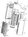
- FIG. 2 illustrates a dispersed perspective view showing a structure according to an embodiment of the present invention.
- the air conditioner includes a main body 2 and an ultrasonic generator 130. More specifically, the main body 2 sucks-in ambient air so as to condition ( i.e. , heat or cool) the inlet air and to discharge the conditioned air.
- the ultrasonic generator 130 installed in the main body 2 and configured to generate ultrasonic waves for repelling (or eliminating) unwanted insects and pests.
- an air inlet 4 for sucking-in air and an air outlet 6 for outputting (or expel) air are formed.
- the main body 2 corresponds to an air conditioning unit, which sucks-in air through the air inlet 4, so as to internally condition (i.e. , heat or cool) the sucked-in air, thereby outputting the conditioned air through the air outlet 6.
- the air conditioning unit may be configured in diverse forms, such as a standing-type air conditioner, a ceiling-embedded air conditioner, or a wall-mounted type air conditioner.
- the wall-mounted type air conditioner will be given as an example in the detailed description of the present invention.
- the main body 2 includes a sash 10, a front frame 20, a suction grill 21, a front panel 28, and an outlet unit 30.
- the air outlet 6 may be formed on the lower surface of the main body 2.
- the front panel 28 may be projected to a forward direction or may be pivoted to an upper direction or a lower direction, so as to configure an air suction path between the front panel 28 and the front surface of the main body 2.
- the main body 2 may be configured so that the air inlet 4 is formed on the upper surface of the main body 2 and that the air outlet 6 is formed on the lower surface of the main body 2.
- the front panel 28 may be positioned to cover the entire surface of the main body 2.
- the main body 2 will be described to be configured of an air inlet 4 being formed on the upper portion of the main body 2 and, most particularly, to the upper surface of the main body 2, and of an air outlet 6 being formed on the lower portion of the main body 2 and, most particularly, to the lower surface of the main body 2.
- the front panel 28 is formed to pivot along the axis of the front panel 28 in a forward direction, so as to service the inside of the main body 2.
- the sash 10 While being mounted on a wall of an indoor space (or area), the sash 10 consists of a case having an air-flow passage allowing air to pass through formed therein and having diverse elements equipped therein.
- the sash 10 includes an air-flow passage guide 12 guiding the air sucked-in through the air inlet 4 to the air outlet 6, and an electric machinery room 13 having various types of electric machinery assembly parts equipped on any one of the left and right sides of the air-flow passage guide 12.
- the air-flow passage guide 12 configures a path of a fan 54.
- the air-flow passage guide 12 includes left and right guides 15 and 16 each being protruded forward from the sash 10, and a center guide 17 between the left and right guides 15 and 16.
- a heat exchanger supporter 18, which supports a heat exchanger 60 and also creates an air path, is equipped on any one of the left and right guides 15 and 16.
- a fan motor 52 is fixed to the electric machinery room 13, wherein a motor installing unit 14 is formed to be protruded in a forward direction.
- the fan motor 52 will be described in a later process.
- a controller 70 controlling the air conditioner is installed in the electric machinery room 13 of the sash 10.
- the controller 70 will also be described in detail in a later process.
- a front frame 20 forms an empty space between the front frame 20 and the sash 10. And, the front frame 20 is placed in front of the sash 10.
- the front frame 20 creates an air-flow path along with the air-flow passage guide 12 and also covers the electric machinery room 13 formed in the sash 10 so as to protect the electric machinery room 13.
- the front frame 20 has openings respectively formed on the top side and the front side, wherein the top side opening functions as the air inlet 4, and wherein the front side opening functions as a service hole for the mounting/dismounting or servicing of a filter 80, which is to be described in a later process.
- the front frame 20 includes front openings 5 that are formed in the front of the air-flow passage guide 12 of the sash 10, so as to be opened back and forth, and also formed on the upper front side of the air-flow passage guide 12 of the sash 10, so as to be opened up and down.
- An inlet grill 21 allows the indoor (or room) air to be sucked into the main body 2 and to protect the lower portion (or surface) of the main body 2.
- the inlet grill 21 is formed in a grill shape in the air inlet 4, which corresponds to the top side opening of the front frame 20.
- An outlet unit 30 guides the conditioned air to be discharged to the outside from the inside of the main body 2 through the air outlet 6.
- the outlet unit 30 is fastened to at least one of the sash 10 and the front frame 20 with a fastening means, such as a fastening member, or with a hooking means, such as a hook.
- the outlet unit 30 includes a drain unit 32 collecting the condensed water dropping from the heat exchanger 60, which will be described in detail in a later process, on the upper portion of the outlet unit 30.
- the drain unit 32 is connected to a drain connection hose 33 guiding the condensed water outside of the main body 2.
- the air outlet 6 is openly formed on the lower portion of the drain unit 32.
- an air-flow direction controller controlling the direction of the air passing through the air outlet 6 is formed in the outlet unit 30.
- the air-flow direction controller includes an air-flow direction controlling member 34 and an air-flow direction controlling member operating device 35.
- the air-flow direction controlling member 34 is formed to rotate along the axis of the man body 2 and, more particularly, along the axis of the outlet unit 30, so as to control the direction of the air being discharged through the air outlet 6.
- the air-flow direction controlling member operating device 35 rotates the air-flow direction controlling member 34.
- the air-flow direction controlling member 34 may include a left/right air-flow direction controlling member, which controls the direction of the air passing though the air outlet 6 in left/right directions, and an up/down air-flow direction controlling member, which controls the direction of the air passing though the air outlet 6 in up/down directions.
- the air-flow direction controlling member operating device 35 may be connected to the left/right air-flow direction controlling member so that the left/right air-flow direction controlling member can rotate along the vertical axis.
- the air-flow direction controlling member operating device 35 may be connected to the up/down air-flow direction controlling member so that the up/down air-flow direction controlling member can rotate along the horizontal axis.
- the air-flow direction controlling member 34 will be described as being rotatably fixed so that any one of the left/right air-flow direction controlling member and the up/down air-flow direction controlling member can open and close the air outlet 6. And, more specifically, the air-flow direction controlling member 34 will be described to have the up/down air-flow direction controlling member fixed to open and close the air outlet 6. Furthermore, the air-flow direction controlling member operating device 35 will be described to include an air-flow direction controlling motor, which is fixed to any one of the left and right sides of the outlet unit 30, thereby rotating the up/down air-flow direction controlling member.
- the air-flow direction controlling member operating device 35 includes a motor having a rotation axis.
- the rotation axis of the motor may be connected to the air-flow direction controlling member 34 so as to directly rotate the air-flow direction controlling member 34.
- the air-flow direction controlling member operating device 35 may also include a motor having a rotation axis, and a driving force transferring member, such as a gear or lever, being connected to the air-flow direction controlling member and to the rotation axis.
- a driving force transferring member such as a gear or lever
- the driving force transferring member may be capable of rotating the air-flow direction controlling member 34.
- the main body 2 includes a ventilator 50, a heat exchanger 60, a controller 70, a filter 80, and a filter frame 90. More specifically, the ventilator 50 draws in (or sucks in) the air through the air inlet 4, so that the air can flow inside of the main body 2, and then discharges the processed air through the air outlet 6.
- the heat exchanger 60 performs heat exchange between the air sucked into the main body 2 and a refrigerant.
- the controller 70 controls the air conditioner.
- the filter 80 cleans the air sucked into the main body 2 through the air inlet 4. And, the filter 80 is mounted on the filter frame 90.
- the ventilator 50 includes a fan motor 52 and a fan 54.
- the fan motor 52 is fixed to the sash 10 and, more particularly, to the motor installing unit 14 formed in the electric machinery room 13.
- the fan 54 is mounted on the rotation axis of the fan motor 52 and is positioned in the air-flow passage guide 12.
- the fan 54 consists of a cross-flow fan being formed to extend from left to right in-between the air-flow passage guides 15, 16, and 17, and, more particularly, between the left/right passage guides 15 and 16.
- the ventilator 50 further includes a motor cover 56 being mounted on the sash 10 so as to cover the fan motor 52.
- the heat exchanger 60 is installed in an empty space of the main body 2 and, more particularly, in a rear-end side of the front portion of the front frame 20, so that the heat exchanger 60 can be positioned between the air inlet 4 and the fan 54. Furthermore, the heat exchanger 60 is installed so that the lower portion of the heat exchanger 60 can be placed above the drain unit 32.
- the heat exchanger 60 includes a vertical portion 62, a forward tilted portion 64, and a backward tilted portion 66. More specifically, the vertical portion 62 is positioned vertically above the drain portion 32. The forward tilted portion 64 is positioned above the vertical portion 62, wherein the rear-end portion is tilted upwards. And, the backward tilted portion 66 is positioned above the forward tilted portion 64, wherein the rear-end portion is tilted downwards.
- the controller 70 includes a control box 72, a main controller 74, and an ultrasonic generator controller 76. More specifically, the control box 72 is installed in the electric machinery room 13 of the main body 2. The main controller 74 is installed in the control box 72 and controls the fan motor 52 of the ventilator 50 and the shielding member operating device 35. Finally, the ultrasonic generator controller 76 controls the ultrasonic generator 100.
- the ultrasonic generator controller 76 is connected to the main controller 74 through a first lead wire 77. And, the ultrasonic generator controller 76 is connected to the ultrasonic generator 100 through a second lead wire 78.
- the filter frame 90 is installed to be positioned between the air inlet 4 and the heat exchanger 60.
- a filter installing room 92 is formed in the filter frame 90.
- air passes through the filter installing room 91 and the filter 80 is mounted (or installed) in the filter installing room 91.
- FIG. 3 illustrates a controlled block view showing a controlled structure according to the embodiment of the present invention.
- the air conditioner according to the embodiment of the present invention further includes a manipulator 40 that can manipulate the operation (or driving) of the main body 2 and that can also input the insect repelling mode.
- the controller 70 controls the fan motor 52 of the ventilator 40, the air-flow direction controlling member operating device 35, and the ultrasonic generator 130 based upon the manipulation of the manipulator 40.
- the controller 70 supplies power to the ultrasonic generator 130 regardless of whether or not the main body 2 is operating the air-conditioning function.
- FIG. 4 illustrates a general cross-sectional view showing a structure according to an embodiment of the present invention.
- an opening 110 having a predetermined size is formed on the main body 2.
- the opening 110 connects the outside of the main body 2 with the inside of the main body 2.
- the opening 110 may be formed by cutting a portion of the sash 10, which configures the frame and the exterior of the main body 2, or a portion of the front frame 20 or the front panel 28.
- the opening 110 may be formed in a circular shape or in other polygonal shapes. In the example given according to the embodiment of the present invention, the opening 110 will be described as being formed in a rectangular shape by cutting a portion of the front panel 28.
- the opening 110 corresponds to a portion allowing the ultrasonic waves generated from the ultrasonic generator 130 to pass through.
- the opening 110 is configured to have a structure regardless of the air inlet 4 and the air outlet 6 being provided in the main body 2 so as to perform the air-conditioning function.
- a mounting room 120 is provided within the main body 2 in a position respective to the opening 110.
- the mounting room 120 creates an installation space 122 that communicates with (or is connected to) the opening 110 from the inside of the main body 2.
- the mounting room 120 configures an installation space 122 that is connected to the outside of the main body 2 through the opening 110.
- an ultrasonic generator 130 and a reflection panel 140 are respectively installed in the installation space 122 of the mounting room 120.
- the mounting room 120 may be divided into a first region and a second region. More specifically, the first region is exposed to the outside through the opening 110 of the main body 2, and the second region is hidden inside the main body 2.
- the ultrasonic generator 130 is installed in the second region of the mounting room 120. Accordingly, the ultrasonic generator 130 may be hidden inside the main body 2 without being exposed to the outside through the opening 110.
- the ultrasonic generator 130 may be mounted in the mounting room 120 so as to be titled upwards or titled downwards, so that the ultrasonic waves being generated from the ultrasonic generator 130 can be discharged towards the opening 110 of the main body 2.
- the mounting room 120 may be formed so that the installation space 122 can be provided to have a predetermined length along the inner surface of the main body 2. Alternatively, the mounting room 120 may also be formed so that the installation space 122 can be provided to have an inclination of a predetermined angle with respect to the inner surface of the main body 2.
- the mounting room 120 is formed to have a predetermined length along the inner surface of the main body 2, so that a portion of the installation space 122 can face into the opening 110, and so that the remaining portion of the installation space 122 can be hidden, thereby being unexposed to the outside.
- the mounting room 120 corresponds to a room for installing the ultrasonic generator 130, which is provided for repelling (or eliminating) unwanted insects or pests existing in the indoor area that in to be air-conditioned by the air conditioner.
- the mounting room 120 may be provided in the front panel 28, which corresponds to the front side portion of the main body 2.
- the mounting room 120 may also be provided in a bottom surface of the front frame 20 or a bottom surface of the sash 10, which respectively correspond to the lower surface of the main body 2.
- the ultrasonic generator 130 and the reflection panel 140 are provided in the main body 2.
- the ultrasonic generator 130 which generates ultrasonic waves, is provided inside the mounting room 120 so as to be hidden from the outside.
- the reflection panel 140 is fixed in the installation space 122 of the mounting room 120 so as to face into the opening 110. Accordingly, the reflection panel 140 can reflect the ultrasonic waves generated from the ultrasonic generator 130 towards the opening 110.
- the reflection panel 140 may be mounted in the mounting room 120 of the main body 2 in a titled (or inclined) state, wherein the reflection panel 140 is inclined to a predetermined angle with respect to the ultrasonic generator 130, so that the ultrasonic waves generated from the ultrasonic generator 130 can be exposed to the outside through the opening 110. Most particularly, the reflection panel 140 may be positioned in the first region of the mounting room 120.
- the ultrasonic generator 130 may be provided so as to be capable of repelling (or eliminating) unwanted insects, regardless of the air-conditioner driving modes, such as a cool air-conditioning mode, a heated air-conditioning mode, a dehumidifying air-conditioning mode, and so on (hereinafter collectively referred to as the“air-conditioning mode”.
- the air-conditioner driving modes such as a cool air-conditioning mode, a heated air-conditioning mode, a dehumidifying air-conditioning mode, and so on (hereinafter collectively referred to as the“air-conditioning mode”.
- the ultrasonic generator 130 may be configured by including a speaker 132 converting the electrical signals to sonic wave (or sound wave) signals, thereby outputting the converted signals to the speaker 132.
- the speaker 132 may be realized with a piezoelectric element.
- the speaker 132 oscillates in accordance with inputted pulse signals, thereby outputting the sonic wave signals.
- the speaker 132 may be mounted on the main body 2 by using a speaker holder 134.
- the ultrasonic generator 130 is provided so that ultrasonic waves can be generated towards the opening 110.
- the ultrasonic generator 130 may output sonic wave (or sound wave) signals of a specific frequency band, so as to repel (or eliminate) unwanted insects (or pests).
- the unwanted insects (or pests) may include flies, mosquitoes, mites, moths, fruit flies, and so on.
- ultrasonic generator 130 generates ultrasonic waves.
- ultrasonic waves refer to sonic waves having a frequency higher than the audio frequency of 20 kilohertz (kHz) that such ultrasonic waves cannot be heard by the human ear.
- the ultrasonic generator 130 generates ultrasonic waves of a specific frequency band high enough to repel (or exterminate) insects depending upon the type of insects.
- the frequency band high enough to repel (or exterminate) insects has a frequency ranging from 20 kHz to 100 kHz.
- the ultrasonic generator 130 may be configured to emit (or generate) sonic waves having different frequency waves depending upon the insect type.
- the ultrasonic generator 130 may be configured to alternately generate ultrasonic waves having different frequencies at predetermined intervals, thereby preventing the insects from developing a tolerance (or resistance) to a particular frequency or being capable of repelling different types of insects at the same time.
- the ultrasonic generator 130 may be configured of a speaker generating ultrasonic waves having a frequency ranging from 20 kHz to 100 kHz by using the oscillation of the piezoelectric element.
- the ultrasonic generator 130 is positioned within the installation space 122 of the mounting room 120, so as to be placed further away from the opening 110. And, the reflection panel 140 is positioned to be in correspondence with the opening 110.
- the mounting room 120 includes an area (or region) exposed to the outside through the opening 110 and an area (or region) hidden and unexposed from the outside.
- the ultrasonic generator 130 is installed in the area within the installation space 122 of the mounting room 120 that is not exposed to the outside, and the reflection panel 140 is installed in the area that is exposed to the outside through the opening 110.
- the reflection panel 140 Since the ultrasonic generator 130 is hidden and unexposed from the outside, the reflection panel 140 is provided to the titled with respect to the ultrasonic generator 130. Accordingly, the reflection panel 140 reflects the ultrasonic waves generated from the ultrasonic generator 130, so that the reflected ultrasonic waves can be delivered to the outside.
- sound waves refer to travelling wave of particles having its physical state changed by an oscillation of an object propagated through a medium (e.g., air).
- a medium e.g., air
- a portion of the sound waves may pass through and another portion of the sound waves may be reflected.
- the reflection panel 140 Since the reflection panel 140 is a structure provided for reflecting ultrasonic waves, the reflection panel 140 should be configured to increase the reflection rate of the sonic waves. Generally, the reflection rate of the sonic waves has the property of increasing more as the density of the material configuring the reflection panel 140 becomes higher and as the surface of the reflection panel 140 is more smoothly formed.
- the high level of the reflection rate of the sonic waves indicates that the absorption coefficient is small.
- the absorption coefficient represents a ratio between incident energy minus the reflected energy and the incident energy, when sonic waves are reflected by an object. Accordingly, it is preferable that the reflection panel 140 has its surface smoothly formed so that the ultrasonic waves can be reflected and that the reflection panel 140 is formed of a material having a high reflection rate of the sonic waves (or a material having a low absorption coefficient).
- the reflection panel 140 is provided to be perpendicular to or tilted within respect to the opening 110.
- the reflection panel 140 is formed to have an insufficiently small size, the generated ultrasonic waves may not be sufficiently reflected and a loss may even occur in some of the ultrasonic waves. Therefore, it is preferable that the reflection panel 140 is formed to have the same surface dimension as the opening 110 or a larger surface dimension than the size of the opening 110.
- the ultrasonic generator 130 may be provided to be perpendicular to the inner surface of the main body 2, and the reflection panel 140 may be provided to be tilted with respect to the opening 110. Accordingly, the reflection panel 140 reflects the ultrasonic waves generated from the ultrasonic generator 130 towards the front portion of the main body 2.
- the ultrasonic generator 130 is provided so that the generated ultrasonic waves can be processed in a perpendicular direction.
- the reflection panel 140 is provided to be tilted with respect to the perpendicular direction of the ultrasonic generator 130.
- the perpendicular direction refers to the gravitational direction with respect to the surface of the earth or the direction opposite to the gravitational direction.
- the mounting positions of the ultrasonic generator and the reflection panel are different from those of the previous embodiment of the present invention. Therefore, detailed descriptions of the other elements configuring this embodiment of the present invention that are identical to those of the embodiment shown in FIG. 1 to FIG. 4 will be omitted for simplicity.
- FIG. 5 illustrates a general cross-sectional view showing a structure according to another embodiment of the present invention.
- an opening 210 is formed on a lower portion of the sash 10.
- a mounting room 220 is provided in a position corresponding to the opening 210.
- the mounting room 220 configures an installation space 222 that is connected to the opening 210 from within the sash 10.
- the mounting room 220 is provided so that the installation room 222 is formed to be titled with respect to the bottom surface of the sash 10.
- a portion of the installation space 222 is formed to face into the opening 210, and the remaining portion of the installation space 222 remains hidden and unexposed from the outside.
- the sash 10 is provided with an ultrasonic generator 230 and a reflection panel 240.
- the ultrasonic generator 230 which generates ultrasonic waves, is provided to be hidden inside the mounting room 220.
- the reflection panel 240 which reflects the ultrasonic waves generated from the ultrasonic generator 230 to the opening 210, is fixed to the installation space 222 of the mounting room 220 that faces into the opening 210.
- the ultrasonic generator 230 is also provided to be titled with respect to the inner surface of the main body 2, and the reflection panel 240 is provided to be perpendicular to the inner surface of the main body 2.
- the ultrasonic generator 230 is provided so that the ultrasonic waves generated from the ultrasonic generator 230 are directed to a direction inclined with respect to the perpendicular direction.
- the flat surface configured by the reflection panel 240 is provided in a perpendicular direction.
- the ultrasonic waves that are generated from the ultrasonic generator 230 in a direction titled downwards are reflected by the reflection panel 240 provided to be perpendicular to the bottom surface of the sash 10. Accordingly, the reflected ultrasonic waves pass through the opening 210.
- an air-conditioner driving mode such as a cool air-conditioning mode, a heated air-conditioning mode, a dehumidifying air-conditioning mode, and so on
- the main controller 72 operates the fan motor 52 and also operates the air-flow direction controlling member operating device 35 in an open mode.
- the air-flow direction controlling member 34 When the open mode of the air-flow direction controlling member operating device 35 is activated, the air-flow direction controlling member 34 is rotated by the air-flow direction controlling member operating device 35, so as to open the air outlet 6. And, when the fan motor 52 is operated, the fan 54 is rotated so as to circulate the air.
- the indoor air is drawn into the inside of the main body 2 through the air inlet 4, and the in-drawn air is purified by the filter 80. Then, the purified air exchanges heat with the heat exchanger 60. Thereafter, the heat-exchanged air passes through the air outlet 6, so as to be guided to the air-flow direction controlling member 34 and discharged.
- the controller 70 When the air-conditioning mode is operated (or activated), as described above, when a swing outlet mode is inputted through the manipulator 40, the controller 70 operates the air-flow direction controlling member operating device 35 both ordinarily (or regularly) and inversely while operating the fan motor 52. Thereafter, the air-flow direction controlling member operating device 35 enables the air-flow direction controlling member 34 to make repeated up-and-down swinging movements. Accordingly, the conditioned air passing through the air outlet 6 is discharged by being vertically dispersed.
- the ultrasonic generator 130 is provided to be hidden inside the main body 2.
- the reflection panel 140 is provided between the opening 110 and the ultrasonic generator 130 so as to be tilted with respect to the ultrasonic generator 130.
- the controller 70 supplies power to the ultrasonic generator 130, so as to allow sonic waves (or sound waves) having a specific frequency band to be generated in order to repel or eliminate unwanted insects.
- the piezoelectric element when power is supplied to the ultrasonic generator 130, the piezoelectric element oscillates, so as to generate ultrasonic waves having a frequency ranging from 20 kHz to 100 kHz.
- the frequency of the ultrasonic waves may be differently set-up depending upon the type of insect that is to be repelled (or eliminated).
- the ultrasonic generator 130 When the insect-repelling mode is activated, as described above, the ultrasonic generator 130 is not exposed to the outside, and the ultrasonic waves generated from the ultrasonic generator 130 are reflected by the reflection panel 140, thereby passing through the opening 110.
- the ultrasonic waves passing through the opening 110 are delivered to the indoor space, thereby leading to the extermination of the unwanted insects caused by a continuous emission of ultrasonic waves.
- FIG. 6 illustrates a perspective view showing the structure of the air conditioner according to preferred embodiment of the present invention.
- FIG. 7 illustrates a perspective view showing a state of a reflection panel being closed according to an embodiment of the present invention.
- FIG. 8 illustrates a general cross-sectional view showing a structure according to an embodiment of the present invention.
- the mounting room, and the mounting structures of the ultrasonic generator and the reflection panel are different from those of the previous embodiment of the present invention. Therefore, detailed descriptions of the other elements configuring this embodiment of the present invention that are identical to those of the embodiment shown in FIG. 1 to FIG. 5 will be omitted for simplicity.
- an opening 110 having a predetermined size is formed on the main body 2.
- the opening 110 connects the outside of the main body 2 with the inside of the main body 2.
- the opening 110 may be formed by cutting a portion of the sash 10, which configures the frame and the exterior of the main body 2, or a portion of the front frame 20 or the front panel 28.
- the opening 110 may be formed in a circular shape or in other polygonal shapes. In the example given according to the embodiment of the present invention, the opening 110 will be described as being formed in a rectangular shape by cutting a portion of the front panel 28.
- the opening 110 corresponds to a portion allowing the ultrasonic waves generated from the ultrasonic generator 330 to pass through.
- the opening 110 is configured to have a structure regardless of the air inlet 4 and the air outlet 6 being provided in the main body 2 so as to perform the air-conditioning function.
- a mounting room 120 is provided in a position corresponding to the opening 110.
- the mounting room 120 creates an installation space 122 that communicates with (or is connected to) the opening 110 from the inside of the main body 2.
- the mounting room 120 may be formed so that the installation space 122 can be provided to have a predetermined length along the inner surface of the main body 2.
- the mounting room 120 may also be formed so that the installation space 122 can be provided to have an inclination of a predetermined angle with respect to the inner surface of the main body 2.
- the mounting room 120 corresponds to a room for installing the ultrasonic generator 330, which is provided for repelling (or eliminating) unwanted insects or pests existing in the indoor area that in to be air-conditioned by the air conditioner.
- the mounting room 120 may be provided in the front panel 28, which corresponds to the front side portion of the main body 2.
- the mounting room 120 may also be provided in a bottom surface of the front frame 20 or a bottom surface of the sash 10, which respectively correspond to the lower surface of the main body 2.
- the ultrasonic generator 130 and the reflection panel 140 are provided in the main body 2.
- the ultrasonic generator 330 which generates ultrasonic waves, is provided inside the mounting room 120 so as to be hidden from the outside.
- the reflection panel 140 is rotatably fixed in the main body 2, so as to selectively shield the opening 110 and to reflect the ultrasonic waves generated from the ultrasonic generator 330.
- the ultrasonic generator 330 may be installed on each of the left and right sides of the main body 2, wherein a left-side ultrasonic generator is installed on the left-side surface of the main body 2, and wherein a right-side ultrasonic generator is installed on the right-side surface of the main body 2, so as to cooperatively attract and repel (or eliminate) the unwanted insects and pests.
- the ultrasonic generator 330 may be fixed to the main body 2 so as to repel (or eliminate) insect and pests.
- the ultrasonic generator 330 may be formed to be protruded to the outside of the main body 2 only when an insect repelling function is activated by the main body 2. In this case, when the insect repelling function is deactivated, or when the air conditioner is turned off, the ultrasonic generator 330 is inserted back into the main body 2 so as to be protected.
- the ultrasonic generator 330 may also be rotatably installed in the main body 2 so as to repel insects by rotating inside of the main body 2.
- the main body 2 may include an ultrasonic generator moving device having a movable motor for moving the ultrasonic generator 330.
- the main body 2 may also include an ultrasonic generator rotating device having a rotatable motor for rotating the ultrasonic generator 330.
- an example of the ultrasonic generator 330 being fixed to the main body 2 will be described according to the embodiment of the present invention.
- the ultrasonic generator 330 may be provided so as to be capable of repelling (or eliminating) unwanted insects, regardless of the air-conditioner driving modes, such as a cool air-conditioning mode, a heated air-conditioning mode, a dehumidifying air-conditioning mode, and so on (hereinafter collectively referred to as the“air-conditioning mode”.
- the air-conditioner driving modes such as a cool air-conditioning mode, a heated air-conditioning mode, a dehumidifying air-conditioning mode, and so on (hereinafter collectively referred to as the“air-conditioning mode”.
- the ultrasonic generator 330 may be configured by including a speaker 332 converting the electrical signals to sonic wave (or sound wave) signals, thereby outputting the converted signals to the speaker 332.
- the speaker 332 may be realized with a piezoelectric element. Herein, the speaker 332 oscillates in accordance with inputted pulse signals, thereby outputting the sonic wave signals.
- the speaker 332 may be mounted on the main body 2 by using a speaker holder 334.
- the ultrasonic generator 130 may be controlled by the controller 70 so as to alternately generate ultrasonic waves having different frequencies at predetermined intervals, thereby preventing the insects from developing a tolerance (or resistance) to a particular frequency or being capable of repelling different types of insects at the same time.
- the reflection panel 340 is provided to reflect the ultrasonic waves generated from the ultrasonic generator 130 to a wanted direction.
- An end of the reflection panel 340 is hinge-joined ( i.e. , joined by hinge) to the main body 2 and rotates within a certain range, so that the other end of the reflection panel 340 can face the front portion of the main body 2. More specifically, the reflection panel 34 has one end hinge-joined to the main body 2 and has another end rotating with respect to the main body 2 at a predetermined angle.
- the reflection panel 340 may also be provided to be connected to a motor (not shown), so that the reflection panel 340 can be rotated.
- the motor providing the driving force for rotating the reflection panel 340 may correspond to a fan motor 52 or an air-flow direction controlling motor. Alternatively, the motor may also correspond to a motor separately configured only to rotate the reflection panel 340.
- the reflection panel 340 when the reflection panel 340 opens the opening 110 and creates a constant inclination with respect to the ultrasonic generator 330, the reflection panel 340 maintains the corresponding position, so as to reflect the ultrasonic waves generated from the ultrasonic generator 330 to the indoor space (or room).
- the reflection panel 340 may repeatedly change its rotation direction, so as to constantly change the reflected direction of the ultrasonic waves.
- the controller 70 may control the reflection panel 340 so as to maintain the inclination angle or to change the inclination angle.
- the reflection panel 340 may protect the ultrasonic generator 330, and, at the same time, when the opening 110 is in an open state, the reflection panel 340 reflects the ultrasonic waves generated from the ultrasonic generator 330 to a wanted direction.
- the reflection panel 340 includes a panel frame 342 and a reflector 344.
- the panel frame 342 may configure the exterior of the main body 2.
- the reflector 344 is provided on the inner surface of the panel frame 342 and reflects the ultrasonic waves generated from the ultrasonic generator 330.
- the outer surface of the reflection panel 340 that is exposed to the outside is configured by the panel frame 342.
- the panel frame 342 is made of the same material as that of the main body 2, so as to realize an overall coordination in the exterior features of the air conditioner.
- the reflector 344 provided on the inner surface of the panel frame 342 is configured of a material that can reflect the sonic waves while minimizing any loss in the ultrasonic waves.
- the reflector 344 may be formed of aluminum or steel, and so on, processed with vacuum vapor deposition on one surface of the panel frame 342. Accordingly, the reflector 344 may be provided by fastening the plate formed of a metallic substance to the panel frame 342.
- the mounting room 120 may be formed of a material that can reflect the ultrasonic waves.
- FIG. 9 illustrates a general cross-sectional view showing a structure according to another embodiment of the present invention.
- the structure of the reflection panel is different from that of the previous embodiments of the present invention. Therefore, detailed descriptions of the other elements configuring this embodiment of the present invention that are identical to those of the embodiment shown in FIG. 1 to FIG. 8 will be omitted for simplicity.
- the ultrasonic generator 420 is provided so that ultrasonic waves can be generated towards the air outlet 6 within the main body 2. At this point, it is preferable that the ultrasonic generator 420 is provided on an upper end or a lower end of the air outlet 6, so that the ultrasonic generator 420 does not interfere with the air-flow passage of the air being discharged through the air outlet 6.
- the reflection panel 440 rotatably provided in the main body 2.
- the reflection panel 440 can control the flowing direction of the air being discharged from the air outlet 6, selectively open and close the air outlet 6, and also reflects the ultrasonic waves generated from the ultrasonic generator 430.
- the reflection panel 440 is provided on the air-flow direction controlling member 34 so as to face into the ultrasonic generator 430.
- the reflection panel 440 is provided on the inner surface of the air-flow direction controlling member 34. Accordingly, the air-flow direction controlling member 34 is unexposed and hidden from the outside, when the air outlet 6 is closed. And, the air-flow direction controlling member 34 is exposed to the outside, when the air outlet 6 is open, thereby reflecting the ultrasonic waves generated from the ultrasonic generator 430.
- the air-flow direction controlling member 34 may include a frame panel and a reflector.
- the frame panel configures the exterior of the main body 2 when the air outlet is in a covered state (i.e. , closed state).
- the reflector is provided on the inner surface of the panel frame.
- the reflection panel 440 and the air-flow direction controlling member 34 are not clearly differentiated from one another. And, if the air-flow direction controlling member 34 is formed of a material that can reflect the ultrasonic waves, the air-flow direction controlling member 34 may replace the reflection panel 440. And, similarly, if the reflection panel 440 is provided in the form of the air-flow direction controlling member 34, the reflection panel 440 may perform both the function of reflecting ultrasonic wave and the function of controlling the air-flow direction.
Abstract
An air conditioner is disclosed. Herein, the air conditioner can maintain the ambient air of a specific space (or area) to a pleasant state by adequately adjusting the temperature, humidity, and air current distribution within the corresponding space to allow people to pleasantly carry out their everyday activities. Since unwanted insects can be repelled or eliminated by using ultrasonic waves that do not contaminate the indoor air, the air conditioner can protect the human body from unwanted insects or pests while maintaining the air within the indoor space to a clean state. Also, by selectively hiding the ultrasonic generator, a reflection panel, which forms the exterior of the main body, may be prevent the ultrasonic generator from being damaged by external impurities. Furthermore, since the reflection panel reflects the ultrasonic waves being generated from the ultrasonic generator to diverse directions, unwanted insects may be efficiently repelled or exterminated.
Description
The present invention relates to an air conditioner that can maintain the ambient air of a specific space (or area) to a pleasant state by adequately adjusting the temperature, humidity, and air current distribution within the corresponding space (or area) to allow people to pleasantly carry out their everyday activities.
Generally, an air conditioner maintains the atmosphere (or ambient air) of a particular space (or area) to a pleasant state by performing cooling and heating function, wherein the air conditioner uses boiling heat or condensation heat of a refrigerant to transfer a cool (or low-temperature) heat source to a heated (or high-temperature) heat source, or to transfer a heated (or high-temperature) heat source to a cool (or low-temperature) heat source, an air purifying (or cleaning) function, wherein the air conditioner purifies (or cleans) polluted air to send out fresh and clean air, and an air circulating function, wherein the air conditioner switches the inside air to and from the outside air.
The above-described air conditioner performs its air-conditioning function within a closed indoor space. At this point, when an insect (or pest) enters the closed space from the outside, the insect may pollute (or contaminate) the indoor environment, thereby causing disease or illness to be spread among the people sharing the corresponding space. During the summer season, when the temperatures are high, people may be infected with highly critical mosquito-borne diseases, such as malaria or the Dengue fever. Most particularly, since the Dengue fever, which is infected by the Dengue mosquito, causes extreme pain and is highly fatal when infected, efforts in trying to prevent such diseases from spreading are required to be made on a nationwide-basis.
However, when using insect repellants or extermination products, such as pesticides or insecticides, in order to repel such insects including mosquitoes, the indoor air (or atmosphere) may be contaminated (o9r polluted) with the same insect-repellant, thereby decreasing the cleaning (or purifying) efficiency of the air conditioner. On the other hand, when no other separate insect repelling products are used, the insects may contaminate the indoor atmosphere by spreading the diseases they are carrying.
Furthermore, generally, even if a structure for repelling insects (hereinafter referred to as an“insect repelling unit”) is added to the air conditioner, such structure is provided in way that the insect repelling unit is exposed to the indoor space. And, in this case, when the air conditioner is turned off, impurities, such as dust or water, may flow into the insect repelling unit, thereby damaging the air conditioner. Also, due to the additional structure of the insect repelling unit, the outside features of the air conditioner may seem more complex.
Accordingly, the present invention is directed to an air conditioner that substantially obviates one or more problems due to limitations and disadvantages of the related art.
Another object of the present invention is to provide an air conditioner that can eliminate (or repel) insect without degrading the air purifying function of the air conditioner.
A further object of the present invention is to provide an air conditioner having a structure for repelling or eliminating unwanted, wherein the insect-repelling structure is hidden and fixed in the inside of the main body, so as to easily repel the unwanted insects or pests.
Additional advantages, objects, and features of the invention will be set forth in part in the description which follows and in part will become apparent to those having ordinary skill in the art upon examination of the following or may be learned from practice of the invention. The objectives and other advantages of the invention may be realized and attained by the structure particularly pointed out in the written description and claims hereof as well as the appended drawings.
To achieve these objects and other advantages and in accordance with the purpose of the invention, as embodied and broadly described herein, an air conditioner includes a main body including an air inlet for drawing in external air, an air outlet for discharging conditioned air to the outside, an opening provided on one side of the main body, and a mounting room communicating with the opening and provided with a predetermined installation space, an ultrasonic generator provided inside the mounting room of the main body and generating ultrasonic waves by using an oscillation of a piezoelectric element, and a reflection panel reflecting the ultrasonic waves generated from the ultrasonic generator to the opening.
In another aspect of the present invention, an air conditioner includes a main body including an air inlet for drawing in external air, an air outlet for discharging conditioned air to the outside, an opening provided on one side of the main body, and a mounting room communicating with the opening and provided with a predetermined installation space, an ultrasonic generator provided inside the mounting room of the main body and generating ultrasonic waves towards the opening by using an oscillation of a piezoelectric element, a reflection panel being rotatably mounted in the main body, so as to open and close the opening of the main body, and reflecting the ultrasonic waves generated from the ultrasonic generator to the outside, and a controller controlling a rotation displacement of the reflection panel and controlling an operation of the ultrasonic generator.
In a further aspect of the present invention, an air conditioner includes a main body including an air inlet for drawing in external air and an air outlet for discharging conditioned air to the outside, an ultrasonic generator provided inside the main body and generating ultrasonic waves towards the air outlet by using an oscillation of a piezoelectric element, a reflection panel selectively opening and closing the air outlet, and reflecting the ultrasonic waves generated from the ultrasonic generator to the outside when the air outlet is in a closed state, and a controller controlling opening and closing operations of the reflection panel and controlling an operation of the ultrasonic generator.
It is to be understood that both the foregoing general description and the following detailed description of the present invention are exemplary and explanatory and are intended to provide further explanation of the invention as claimed.
According to the embodiment of the present invention, the ultrasonic waves generated from the ultrasonic generator can be reflected to the indoor area.
The accompanying drawings, which are included to provide a further understanding of the invention and are incorporated in and constitute a part of this application, illustrate embodiment(s) of the invention and together with the description serve to explain the principle of the invention. In the drawings:
FIG. 1 illustrates a perspective view showing a structure of an air conditioner according to a preferred embodiment of the present invention;
FIG. 2 illustrates a dispersed perspective view of the structure according to an embodiment of the present invention;
FIG. 3 illustrates a controlled block view showing a controlled structure according to the embodiment of the present invention;
FIG. 4 illustrates a general cross-sectional view showing a structure according to an embodiment of the present invention;
FIG. 5 illustrates a general cross-sectional view showing a structure according to another embodiment of the present invention;
FIG. 6 illustrates a perspective view showing the structure of the air conditioner according to preferred embodiment of the present invention;
FIG. 7 illustrates a perspective view showing a state of a reflection panel being closed according to an embodiment of the present invention;
FIG. 8 illustrates a general cross-sectional view showing a structure according to an embodiment of the present invention; and
FIG. 9 illustrates a general cross-sectional view showing a structure according to another embodiment of the present invention.
In the following detailed description, reference is made to the accompanying drawing from a part hereof, and which show by way of illustration specific embodiments of the invention. It is to be understood by toe of ordinary skill in this technological field that other embodiments may be utilized, and structural, electrical, as well as procedural changes may be made without departing from the scope of the present invention. Wherever possible, the same reference numbers will be used throughout the drawings to refer to the same or similar parts.
In the following description of the present invention, the air conditioner may include an air conditioner, a ventilator, an air cleaner, and so on.
FIG. 1 illustrates a perspective view showing a structure of an air conditioner according to a preferred embodiment of the present invention. And, FIG. 2 illustrates a dispersed perspective view showing a structure according to an embodiment of the present invention.
Referring to FIG. 1 and FIG. 2, the air conditioner according to the embodiment of the present invention includes a main body 2 and an ultrasonic generator 130. More specifically, the main body 2 sucks-in ambient air so as to condition (i.e., heat or cool) the inlet air and to discharge the conditioned air. The ultrasonic generator 130 installed in the main body 2 and configured to generate ultrasonic waves for repelling (or eliminating) unwanted insects and pests.
In the main body 2, an air inlet 4 for sucking-in air and an air outlet 6 for outputting (or expel) air are formed.
More specifically, the main body 2 corresponds to an air conditioning unit, which sucks-in air through the air inlet 4, so as to internally condition (i.e., heat or cool) the sucked-in air, thereby outputting the conditioned air through the air outlet 6. Herein, the air conditioning unit may be configured in diverse forms, such as a standing-type air conditioner, a ceiling-embedded air conditioner, or a wall-mounted type air conditioner. Hereinafter, the wall-mounted type air conditioner will be given as an example in the detailed description of the present invention.
The main body 2 includes a sash 10, a front frame 20, a suction grill 21, a front panel 28, and an outlet unit 30.
In addition to the air inlet 4 being formed on the front surface and upper surface of the main body 2, the air outlet 6 may be formed on the lower surface of the main body 2. And, the front panel 28 may be projected to a forward direction or may be pivoted to an upper direction or a lower direction, so as to configure an air suction path between the front panel 28 and the front surface of the main body 2.
The main body 2 may be configured so that the air inlet 4 is formed on the upper surface of the main body 2 and that the air outlet 6 is formed on the lower surface of the main body 2. And, the front panel 28 may be positioned to cover the entire surface of the main body 2.
Hereinafter, in the description of the air conditioner according to the present invention, the main body 2 will be described to be configured of an air inlet 4 being formed on the upper portion of the main body 2 and, most particularly, to the upper surface of the main body 2, and of an air outlet 6 being formed on the lower portion of the main body 2 and, most particularly, to the lower surface of the main body 2. Also, in addition to configuring the front area of the outside features of the air conditioner according to the present invention, the front panel 28 is formed to pivot along the axis of the front panel 28 in a forward direction, so as to service the inside of the main body 2.
While being mounted on a wall of an indoor space (or area), the sash 10 consists of a case having an air-flow passage allowing air to pass through formed therein and having diverse elements equipped therein.
The sash 10 includes an air-flow passage guide 12 guiding the air sucked-in through the air inlet 4 to the air outlet 6, and an electric machinery room 13 having various types of electric machinery assembly parts equipped on any one of the left and right sides of the air-flow passage guide 12.
The air-flow passage guide 12 configures a path of a fan 54. Herein, the air-flow passage guide 12 includes left and right guides 15 and 16 each being protruded forward from the sash 10, and a center guide 17 between the left and right guides 15 and 16.
A heat exchanger supporter 18, which supports a heat exchanger 60 and also creates an air path, is equipped on any one of the left and right guides 15 and 16.
A fan motor 52 is fixed to the electric machinery room 13, wherein a motor installing unit 14 is formed to be protruded in a forward direction. Herein, the fan motor 52 will be described in a later process.
A controller 70 controlling the air conditioner is installed in the electric machinery room 13 of the sash 10. Herein, the controller 70 will also be described in detail in a later process.
A front frame 20 forms an empty space between the front frame 20 and the sash 10. And, the front frame 20 is placed in front of the sash 10.
The front frame 20 creates an air-flow path along with the air-flow passage guide 12 and also covers the electric machinery room 13 formed in the sash 10 so as to protect the electric machinery room 13.
The front frame 20 has openings respectively formed on the top side and the front side, wherein the top side opening functions as the air inlet 4, and wherein the front side opening functions as a service hole for the mounting/dismounting or servicing of a filter 80, which is to be described in a later process.
The front frame 20 includes front openings 5 that are formed in the front of the air-flow passage guide 12 of the sash 10, so as to be opened back and forth, and also formed on the upper front side of the air-flow passage guide 12 of the sash 10, so as to be opened up and down.
An inlet grill 21 allows the indoor (or room) air to be sucked into the main body 2 and to protect the lower portion (or surface) of the main body 2. The inlet grill 21 is formed in a grill shape in the air inlet 4, which corresponds to the top side opening of the front frame 20.
An outlet unit 30 guides the conditioned air to be discharged to the outside from the inside of the main body 2 through the air outlet 6. Herein, the outlet unit 30 is fastened to at least one of the sash 10 and the front frame 20 with a fastening means, such as a fastening member, or with a hooking means, such as a hook.
The outlet unit 30 includes a drain unit 32 collecting the condensed water dropping from the heat exchanger 60, which will be described in detail in a later process, on the upper portion of the outlet unit 30. The drain unit 32 is connected to a drain connection hose 33 guiding the condensed water outside of the main body 2. And, the air outlet 6 is openly formed on the lower portion of the drain unit 32.
Also, an air-flow direction controller controlling the direction of the air passing through the air outlet 6 is formed in the outlet unit 30.
The air-flow direction controller includes an air-flow direction controlling member 34 and an air-flow direction controlling member operating device 35. Herein, the air-flow direction controlling member 34 is formed to rotate along the axis of the man body 2 and, more particularly, along the axis of the outlet unit 30, so as to control the direction of the air being discharged through the air outlet 6. Also, the air-flow direction controlling member operating device 35 rotates the air-flow direction controlling member 34.
The air-flow direction controlling member 34 may include a left/right air-flow direction controlling member, which controls the direction of the air passing though the air outlet 6 in left/right directions, and an up/down air-flow direction controlling member, which controls the direction of the air passing though the air outlet 6 in up/down directions.
The air-flow direction controlling member operating device 35 may be connected to the left/right air-flow direction controlling member so that the left/right air-flow direction controlling member can rotate along the vertical axis. Alternatively, the air-flow direction controlling member operating device 35 may be connected to the up/down air-flow direction controlling member so that the up/down air-flow direction controlling member can rotate along the horizontal axis.
Hereinafter, the air-flow direction controlling member 34 will be described as being rotatably fixed so that any one of the left/right air-flow direction controlling member and the up/down air-flow direction controlling member can open and close the air outlet 6. And, more specifically, the air-flow direction controlling member 34 will be described to have the up/down air-flow direction controlling member fixed to open and close the air outlet 6. Furthermore, the air-flow direction controlling member operating device 35 will be described to include an air-flow direction controlling motor, which is fixed to any one of the left and right sides of the outlet unit 30, thereby rotating the up/down air-flow direction controlling member.
The air-flow direction controlling member operating device 35 includes a motor having a rotation axis. Herein, the rotation axis of the motor may be connected to the air-flow direction controlling member 34 so as to directly rotate the air-flow direction controlling member 34.
Alternatively, the air-flow direction controlling member operating device 35 may also include a motor having a rotation axis, and a driving force transferring member, such as a gear or lever, being connected to the air-flow direction controlling member and to the rotation axis. Herein, when the motor rotates, the driving force transferring member may be capable of rotating the air-flow direction controlling member 34.
The main body 2 includes a ventilator 50, a heat exchanger 60, a controller 70, a filter 80, and a filter frame 90. More specifically, the ventilator 50 draws in (or sucks in) the air through the air inlet 4, so that the air can flow inside of the main body 2, and then discharges the processed air through the air outlet 6. The heat exchanger 60 performs heat exchange between the air sucked into the main body 2 and a refrigerant. The controller 70 controls the air conditioner. The filter 80 cleans the air sucked into the main body 2 through the air inlet 4. And, the filter 80 is mounted on the filter frame 90.
The ventilator 50 includes a fan motor 52 and a fan 54. Herein, the fan motor 52 is fixed to the sash 10 and, more particularly, to the motor installing unit 14 formed in the electric machinery room 13. The fan 54 is mounted on the rotation axis of the fan motor 52 and is positioned in the air-flow passage guide 12.
The fan 54 consists of a cross-flow fan being formed to extend from left to right in-between the air-flow passage guides 15, 16, and 17, and, more particularly, between the left/right passage guides 15 and 16.
The ventilator 50 further includes a motor cover 56 being mounted on the sash 10 so as to cover the fan motor 52.
The heat exchanger 60 is installed in an empty space of the main body 2 and, more particularly, in a rear-end side of the front portion of the front frame 20, so that the heat exchanger 60 can be positioned between the air inlet 4 and the fan 54. Furthermore, the heat exchanger 60 is installed so that the lower portion of the heat exchanger 60 can be placed above the drain unit 32.
The heat exchanger 60 includes a vertical portion 62, a forward tilted portion 64, and a backward tilted portion 66. More specifically, the vertical portion 62 is positioned vertically above the drain portion 32. The forward tilted portion 64 is positioned above the vertical portion 62, wherein the rear-end portion is tilted upwards. And, the backward tilted portion 66 is positioned above the forward tilted portion 64, wherein the rear-end portion is tilted downwards.
The controller 70 includes a control box 72, a main controller 74, and an ultrasonic generator controller 76. More specifically, the control box 72 is installed in the electric machinery room 13 of the main body 2. The main controller 74 is installed in the control box 72 and controls the fan motor 52 of the ventilator 50 and the shielding member operating device 35. Finally, the ultrasonic generator controller 76 controls the ultrasonic generator 100.
The ultrasonic generator controller 76 is connected to the main controller 74 through a first lead wire 77. And, the ultrasonic generator controller 76 is connected to the ultrasonic generator 100 through a second lead wire 78.
The filter frame 90 is installed to be positioned between the air inlet 4 and the heat exchanger 60. A filter installing room 92 is formed in the filter frame 90. Herein, air passes through the filter installing room 91 and the filter 80 is mounted (or installed) in the filter installing room 91.
FIG. 3 illustrates a controlled block view showing a controlled structure according to the embodiment of the present invention.
Referring to FIG. 3, the air conditioner according to the embodiment of the present invention further includes a manipulator 40 that can manipulate the operation (or driving) of the main body 2 and that can also input the insect repelling mode. The controller 70 controls the fan motor 52 of the ventilator 40, the air-flow direction controlling member operating device 35, and the ultrasonic generator 130 based upon the manipulation of the manipulator 40.
When the insect repelling mode is inputted through the manipulator 40, the controller 70 supplies power to the ultrasonic generator 130 regardless of whether or not the main body 2 is operating the air-conditioning function.
FIG. 4 illustrates a general cross-sectional view showing a structure according to an embodiment of the present invention.
Referring to FIG. 4, an opening 110 having a predetermined size is formed on the main body 2. Herein, the opening 110 connects the outside of the main body 2 with the inside of the main body 2. The opening 110 may be formed by cutting a portion of the sash 10, which configures the frame and the exterior of the main body 2, or a portion of the front frame 20 or the front panel 28. The opening 110 may be formed in a circular shape or in other polygonal shapes. In the example given according to the embodiment of the present invention, the opening 110 will be described as being formed in a rectangular shape by cutting a portion of the front panel 28.
The opening 110 corresponds to a portion allowing the ultrasonic waves generated from the ultrasonic generator 130 to pass through. Herein, the opening 110 is configured to have a structure regardless of the air inlet 4 and the air outlet 6 being provided in the main body 2 so as to perform the air-conditioning function.
A mounting room 120 is provided within the main body 2 in a position respective to the opening 110. The mounting room 120 creates an installation space 122 that communicates with (or is connected to) the opening 110 from the inside of the main body 2.
In other words, the mounting room 120 configures an installation space 122 that is connected to the outside of the main body 2 through the opening 110. Herein, an ultrasonic generator 130 and a reflection panel 140 are respectively installed in the installation space 122 of the mounting room 120.
Also, the mounting room 120 may be divided into a first region and a second region. More specifically, the first region is exposed to the outside through the opening 110 of the main body 2, and the second region is hidden inside the main body 2. Herein, the ultrasonic generator 130 is installed in the second region of the mounting room 120. Accordingly, the ultrasonic generator 130 may be hidden inside the main body 2 without being exposed to the outside through the opening 110.
Moreover, the ultrasonic generator 130 may be mounted in the mounting room 120 so as to be titled upwards or titled downwards, so that the ultrasonic waves being generated from the ultrasonic generator 130 can be discharged towards the opening 110 of the main body 2.
The mounting room 120 may be formed so that the installation space 122 can be provided to have a predetermined length along the inner surface of the main body 2. Alternatively, the mounting room 120 may also be formed so that the installation space 122 can be provided to have an inclination of a predetermined angle with respect to the inner surface of the main body 2.
In the embodiment of the present invention, the mounting room 120 is formed to have a predetermined length along the inner surface of the main body 2, so that a portion of the installation space 122 can face into the opening 110, and so that the remaining portion of the installation space 122 can be hidden, thereby being unexposed to the outside.
The mounting room 120 corresponds to a room for installing the ultrasonic generator 130, which is provided for repelling (or eliminating) unwanted insects or pests existing in the indoor area that in to be air-conditioned by the air conditioner. Herein, the mounting room 120 may be provided in the front panel 28, which corresponds to the front side portion of the main body 2. Alternatively, the mounting room 120 may also be provided in a bottom surface of the front frame 20 or a bottom surface of the sash 10, which respectively correspond to the lower surface of the main body 2.
Furthermore, the ultrasonic generator 130 and the reflection panel 140 are provided in the main body 2. Herein, the ultrasonic generator 130, which generates ultrasonic waves, is provided inside the mounting room 120 so as to be hidden from the outside. And, the reflection panel 140 is fixed in the installation space 122 of the mounting room 120 so as to face into the opening 110. Accordingly, the reflection panel 140 can reflect the ultrasonic waves generated from the ultrasonic generator 130 towards the opening 110.
The reflection panel 140 may be mounted in the mounting room 120 of the main body 2 in a titled (or inclined) state, wherein the reflection panel 140 is inclined to a predetermined angle with respect to the ultrasonic generator 130, so that the ultrasonic waves generated from the ultrasonic generator 130 can be exposed to the outside through the opening 110. Most particularly, the reflection panel 140 may be positioned in the first region of the mounting room 120.
The ultrasonic generator 130 may be provided so as to be capable of repelling (or eliminating) unwanted insects, regardless of the air-conditioner driving modes, such as a cool air-conditioning mode, a heated air-conditioning mode, a dehumidifying air-conditioning mode, and so on (hereinafter collectively referred to as the“air-conditioning mode”.
The ultrasonic generator 130 may be configured by including a speaker 132 converting the electrical signals to sonic wave (or sound wave) signals, thereby outputting the converted signals to the speaker 132. The speaker 132 may be realized with a piezoelectric element. Herein, the speaker 132 oscillates in accordance with inputted pulse signals, thereby outputting the sonic wave signals. The speaker 132 may be mounted on the main body 2 by using a speaker holder 134.
The ultrasonic generator 130 is provided so that ultrasonic waves can be generated towards the opening 110. The ultrasonic generator 130 may output sonic wave (or sound wave) signals of a specific frequency band, so as to repel (or eliminate) unwanted insects (or pests). Herein, examples of the unwanted insects (or pests) may include flies, mosquitoes, mites, moths, fruit flies, and so on.
More specifically, the ultrasonic generator 130 generates ultrasonic waves. Herein, ultrasonic waves refer to sonic waves having a frequency higher than the audio frequency of 20 kilohertz (kHz) that such ultrasonic waves cannot be heard by the human ear.
According to the embodiment of the present invention, the ultrasonic generator 130 generates ultrasonic waves of a specific frequency band high enough to repel (or exterminate) insects depending upon the type of insects. Herein, it is preferable that the frequency band high enough to repel (or exterminate) insects has a frequency ranging from 20 kHz to 100 kHz.
Within the above-mentioned frequency band range, since different frequency bands are required to repel each insect type, such as flies, mosquitoes, mites, moths, fruit flies, and so on, the ultrasonic generator 130 may be configured to emit (or generate) sonic waves having different frequency waves depending upon the insect type.
Furthermore, the ultrasonic generator 130 may be configured to alternately generate ultrasonic waves having different frequencies at predetermined intervals, thereby preventing the insects from developing a tolerance (or resistance) to a particular frequency or being capable of repelling different types of insects at the same time.
More specifically, the ultrasonic generator 130 may be configured of a speaker generating ultrasonic waves having a frequency ranging from 20 kHz to 100 kHz by using the oscillation of the piezoelectric element.
For example, when an ultrasonic generator 130 using a power of 12 volts in a closed space of 190*190*190 cm2 generates a frequency ranging from 20 kHz to 100 kHz, after a period of 24 hours, the Dengue mosquito marks a death rate of 74%, and the Malaria mosquito marks a death rate of 100%. When compared with the natural death rate (approximately 7% to 8%) of mosquitoes that are not exposed to ultrasonic waves under the same air-conditioned atmosphere, the above-mentioned death rates proves the fact that ultrasonic waves may act as a fatal factor that can lead to the death and extermination of mosquitoes.
The ultrasonic generator 130 is positioned within the installation space 122 of the mounting room 120, so as to be placed further away from the opening 110. And, the reflection panel 140 is positioned to be in correspondence with the opening 110.
More specifically, the mounting room 120 includes an area (or region) exposed to the outside through the opening 110 and an area (or region) hidden and unexposed from the outside. Herein, the ultrasonic generator 130 is installed in the area within the installation space 122 of the mounting room 120 that is not exposed to the outside, and the reflection panel 140 is installed in the area that is exposed to the outside through the opening 110.
Since the ultrasonic generator 130 is hidden and unexposed from the outside, the reflection panel 140 is provided to the titled with respect to the ultrasonic generator 130. Accordingly, the reflection panel 140 reflects the ultrasonic waves generated from the ultrasonic generator 130, so that the reflected ultrasonic waves can be delivered to the outside.
Generally, sound waves (or sonic waves) refer to travelling wave of particles having its physical state changed by an oscillation of an object propagated through a medium (e.g., air). Herein, being similar to light rays, when emitted to boundary surfaces of different media, a portion of the sound waves may pass through and another portion of the sound waves may be reflected.
Since the reflection panel 140 is a structure provided for reflecting ultrasonic waves, the reflection panel 140 should be configured to increase the reflection rate of the sonic waves. Generally, the reflection rate of the sonic waves has the property of increasing more as the density of the material configuring the reflection panel 140 becomes higher and as the surface of the reflection panel 140 is more smoothly formed.
Also, the high level of the reflection rate of the sonic waves indicates that the absorption coefficient is small. Herein, the absorption coefficient represents a ratio between incident energy minus the reflected energy and the incident energy, when sonic waves are reflected by an object. Accordingly, it is preferable that the reflection panel 140 has its surface smoothly formed so that the ultrasonic waves can be reflected and that the reflection panel 140 is formed of a material having a high reflection rate of the sonic waves (or a material having a low absorption coefficient).
Also, the reflection panel 140 is provided to be perpendicular to or tilted within respect to the opening 110. Herein, if the reflection panel 140 is formed to have an insufficiently small size, the generated ultrasonic waves may not be sufficiently reflected and a loss may even occur in some of the ultrasonic waves. Therefore, it is preferable that the reflection panel 140 is formed to have the same surface dimension as the opening 110 or a larger surface dimension than the size of the opening 110.
In this embodiment of the present invention, the ultrasonic generator 130 may be provided to be perpendicular to the inner surface of the main body 2, and the reflection panel 140 may be provided to be tilted with respect to the opening 110. Accordingly, the reflection panel 140 reflects the ultrasonic waves generated from the ultrasonic generator 130 towards the front portion of the main body 2.
In other words, the ultrasonic generator 130 is provided so that the generated ultrasonic waves can be processed in a perpendicular direction. And, the reflection panel 140 is provided to be tilted with respect to the perpendicular direction of the ultrasonic generator 130. At this point, the perpendicular direction refers to the gravitational direction with respect to the surface of the earth or the direction opposite to the gravitational direction.
Hereinafter, the air conditioner according to another embodiment of the present invention will be described in detail with reference to the accompanying drawings.
In this embodiment of the present invention, the mounting positions of the ultrasonic generator and the reflection panel are different from those of the previous embodiment of the present invention. Therefore, detailed descriptions of the other elements configuring this embodiment of the present invention that are identical to those of the embodiment shown in FIG. 1 to FIG. 4 will be omitted for simplicity.
FIG. 5 illustrates a general cross-sectional view showing a structure according to another embodiment of the present invention.
Referring to FIG. 5, according to this embodiment of the present invention, an opening 210 is formed on a lower portion of the sash 10. A mounting room 220 is provided in a position corresponding to the opening 210. The mounting room 220 configures an installation space 222 that is connected to the opening 210 from within the sash 10. The mounting room 220 is provided so that the installation room 222 is formed to be titled with respect to the bottom surface of the sash 10.
A portion of the installation space 222 is formed to face into the opening 210, and the remaining portion of the installation space 222 remains hidden and unexposed from the outside.
The sash 10 is provided with an ultrasonic generator 230 and a reflection panel 240. The ultrasonic generator 230, which generates ultrasonic waves, is provided to be hidden inside the mounting room 220. And, the reflection panel 240, which reflects the ultrasonic waves generated from the ultrasonic generator 230 to the opening 210, is fixed to the installation space 222 of the mounting room 220 that faces into the opening 210.
Since the mounting room 220 is provided to be titled with respect to the bottom surface of the sash 10, the ultrasonic generator 230 is also provided to be titled with respect to the inner surface of the main body 2, and the reflection panel 240 is provided to be perpendicular to the inner surface of the main body 2.
In other words, the ultrasonic generator 230 is provided so that the ultrasonic waves generated from the ultrasonic generator 230 are directed to a direction inclined with respect to the perpendicular direction. The flat surface configured by the reflection panel 240 is provided in a perpendicular direction.
Therefore, the ultrasonic waves that are generated from the ultrasonic generator 230 in a direction titled downwards, are reflected by the reflection panel 240 provided to be perpendicular to the bottom surface of the sash 10. Accordingly, the reflected ultrasonic waves pass through the opening 210.
Hereinafter, the operations of the air conditioner according to the present invention having the above-described structure will now be described in detail.
First of all, when an air-conditioner driving mode, such as a cool air-conditioning mode, a heated air-conditioning mode, a dehumidifying air-conditioning mode, and so on, is inputted through the manipulator 40, and when the insect-repelling mode is not inputted, the main controller 72 operates the fan motor 52 and also operates the air-flow direction controlling member operating device 35 in an open mode.
When the open mode of the air-flow direction controlling member operating device 35 is activated, the air-flow direction controlling member 34 is rotated by the air-flow direction controlling member operating device 35, so as to open the air outlet 6. And, when the fan motor 52 is operated, the fan 54 is rotated so as to circulate the air.
When the fan 54 is rotated, the indoor air is drawn into the inside of the main body 2 through the air inlet 4, and the in-drawn air is purified by the filter 80. Then, the purified air exchanges heat with the heat exchanger 60. Thereafter, the heat-exchanged air passes through the air outlet 6, so as to be guided to the air-flow direction controlling member 34 and discharged.
When the air-conditioning mode is operated (or activated), as described above, when a swing outlet mode is inputted through the manipulator 40, the controller 70 operates the air-flow direction controlling member operating device 35 both ordinarily (or regularly) and inversely while operating the fan motor 52. Thereafter, the air-flow direction controlling member operating device 35 enables the air-flow direction controlling member 34 to make repeated up-and-down swinging movements. Accordingly, the conditioned air passing through the air outlet 6 is discharged by being vertically dispersed.
Meanwhile, the ultrasonic generator 130 is provided to be hidden inside the main body 2. And, the reflection panel 140 is provided between the opening 110 and the ultrasonic generator 130 so as to be tilted with respect to the ultrasonic generator 130.
When an insect repelling mode is inputted by the user through the manipulator 40 during the operation of the air-conditioning mode, or after the operation of the air-conditioner is stopped, the controller 70 supplies power to the ultrasonic generator 130, so as to allow sonic waves (or sound waves) having a specific frequency band to be generated in order to repel or eliminate unwanted insects.
More specifically, when power is supplied to the ultrasonic generator 130, the piezoelectric element oscillates, so as to generate ultrasonic waves having a frequency ranging from 20 kHz to 100 kHz. Herein, the frequency of the ultrasonic waves may be differently set-up depending upon the type of insect that is to be repelled (or eliminated).
When the insect-repelling mode is activated, as described above, the ultrasonic generator 130 is not exposed to the outside, and the ultrasonic waves generated from the ultrasonic generator 130 are reflected by the reflection panel 140, thereby passing through the opening 110.
The ultrasonic waves passing through the opening 110 are delivered to the indoor space, thereby leading to the extermination of the unwanted insects caused by a continuous emission of ultrasonic waves.
FIG. 6 illustrates a perspective view showing the structure of the air conditioner according to preferred embodiment of the present invention. FIG. 7 illustrates a perspective view showing a state of a reflection panel being closed according to an embodiment of the present invention. And, FIG. 8 illustrates a general cross-sectional view showing a structure according to an embodiment of the present invention.
In this embodiment of the present invention, the mounting room, and the mounting structures of the ultrasonic generator and the reflection panel are different from those of the previous embodiment of the present invention. Therefore, detailed descriptions of the other elements configuring this embodiment of the present invention that are identical to those of the embodiment shown in FIG. 1 to FIG. 5 will be omitted for simplicity.
Referring to FIG. 6 to FIG. 8, an opening 110 having a predetermined size is formed on the main body 2. Herein, the opening 110 connects the outside of the main body 2 with the inside of the main body 2. The opening 110 may be formed by cutting a portion of the sash 10, which configures the frame and the exterior of the main body 2, or a portion of the front frame 20 or the front panel 28. The opening 110 may be formed in a circular shape or in other polygonal shapes. In the example given according to the embodiment of the present invention, the opening 110 will be described as being formed in a rectangular shape by cutting a portion of the front panel 28.
The opening 110 corresponds to a portion allowing the ultrasonic waves generated from the ultrasonic generator 330 to pass through. Herein, the opening 110 is configured to have a structure regardless of the air inlet 4 and the air outlet 6 being provided in the main body 2 so as to perform the air-conditioning function.
A mounting room 120 is provided in a position corresponding to the opening 110. The mounting room 120 creates an installation space 122 that communicates with (or is connected to) the opening 110 from the inside of the main body 2. The mounting room 120 may be formed so that the installation space 122 can be provided to have a predetermined length along the inner surface of the main body 2. Alternatively, the mounting room 120 may also be formed so that the installation space 122 can be provided to have an inclination of a predetermined angle with respect to the inner surface of the main body 2.
The mounting room 120 corresponds to a room for installing the ultrasonic generator 330, which is provided for repelling (or eliminating) unwanted insects or pests existing in the indoor area that in to be air-conditioned by the air conditioner. Herein, the mounting room 120 may be provided in the front panel 28, which corresponds to the front side portion of the main body 2. Alternatively, the mounting room 120 may also be provided in a bottom surface of the front frame 20 or a bottom surface of the sash 10, which respectively correspond to the lower surface of the main body 2.
Furthermore, the ultrasonic generator 130 and the reflection panel 140 are provided in the main body 2. Herein, the ultrasonic generator 330, which generates ultrasonic waves, is provided inside the mounting room 120 so as to be hidden from the outside. And, the reflection panel 140 is rotatably fixed in the main body 2, so as to selectively shield the opening 110 and to reflect the ultrasonic waves generated from the ultrasonic generator 330.
The ultrasonic generator 330 may be installed on each of the left and right sides of the main body 2, wherein a left-side ultrasonic generator is installed on the left-side surface of the main body 2, and wherein a right-side ultrasonic generator is installed on the right-side surface of the main body 2, so as to cooperatively attract and repel (or eliminate) the unwanted insects and pests.
The ultrasonic generator 330 may be fixed to the main body 2 so as to repel (or eliminate) insect and pests. Alternatively, the ultrasonic generator 330 may be formed to be protruded to the outside of the main body 2 only when an insect repelling function is activated by the main body 2. In this case, when the insect repelling function is deactivated, or when the air conditioner is turned off, the ultrasonic generator 330 is inserted back into the main body 2 so as to be protected. Furthermore, the ultrasonic generator 330 may also be rotatably installed in the main body 2 so as to repel insects by rotating inside of the main body 2.
The main body 2 may include an ultrasonic generator moving device having a movable motor for moving the ultrasonic generator 330. The main body 2 may also include an ultrasonic generator rotating device having a rotatable motor for rotating the ultrasonic generator 330. Hereinafter, an example of the ultrasonic generator 330 being fixed to the main body 2 will be described according to the embodiment of the present invention.
The ultrasonic generator 330 may be provided so as to be capable of repelling (or eliminating) unwanted insects, regardless of the air-conditioner driving modes, such as a cool air-conditioning mode, a heated air-conditioning mode, a dehumidifying air-conditioning mode, and so on (hereinafter collectively referred to as the“air-conditioning mode”.
The ultrasonic generator 330 may be configured by including a speaker 332 converting the electrical signals to sonic wave (or sound wave) signals, thereby outputting the converted signals to the speaker 332. The speaker 332 may be realized with a piezoelectric element. Herein, the speaker 332 oscillates in accordance with inputted pulse signals, thereby outputting the sonic wave signals. The speaker 332 may be mounted on the main body 2 by using a speaker holder 334.
Furthermore, the ultrasonic generator 130 may be controlled by the controller 70 so as to alternately generate ultrasonic waves having different frequencies at predetermined intervals, thereby preventing the insects from developing a tolerance (or resistance) to a particular frequency or being capable of repelling different types of insects at the same time.
The reflection panel 340 is provided to reflect the ultrasonic waves generated from the ultrasonic generator 130 to a wanted direction.
An end of the reflection panel 340 is hinge-joined (i.e., joined by hinge) to the main body 2 and rotates within a certain range, so that the other end of the reflection panel 340 can face the front portion of the main body 2. More specifically, the reflection panel 34 has one end hinge-joined to the main body 2 and has another end rotating with respect to the main body 2 at a predetermined angle. The reflection panel 340 may also be provided to be connected to a motor (not shown), so that the reflection panel 340 can be rotated. At this point, the motor providing the driving force for rotating the reflection panel 340 may correspond to a fan motor 52 or an air-flow direction controlling motor. Alternatively, the motor may also correspond to a motor separately configured only to rotate the reflection panel 340.
Also, when the reflection panel 340 opens the opening 110 and creates a constant inclination with respect to the ultrasonic generator 330, the reflection panel 340 maintains the corresponding position, so as to reflect the ultrasonic waves generated from the ultrasonic generator 330 to the indoor space (or room). Herein, when the opening 110 is in an open state, the reflection panel 340 may repeatedly change its rotation direction, so as to constantly change the reflected direction of the ultrasonic waves.
More specifically, when the reflection panel 340 opens the opening 110 in an inclined state at a predetermined angle with respect to the ultrasonic generator 330, the controller 70 may control the reflection panel 340 so as to maintain the inclination angle or to change the inclination angle.
When the reflection angle 340 selectively shields the opening 110 by its rotation movements, thereby stopping the operation of the ultrasonic generator 330, the reflection panel 340 may protect the ultrasonic generator 330, and, at the same time, when the opening 110 is in an open state, the reflection panel 340 reflects the ultrasonic waves generated from the ultrasonic generator 330 to a wanted direction.
The reflection panel 340 includes a panel frame 342 and a reflector 344. Herein, with the shielding of the opening 110, the panel frame 342 may configure the exterior of the main body 2. Also, the reflector 344 is provided on the inner surface of the panel frame 342 and reflects the ultrasonic waves generated from the ultrasonic generator 330.
More specifically, the outer surface of the reflection panel 340 that is exposed to the outside is configured by the panel frame 342. Herein, it is preferable that the panel frame 342 is made of the same material as that of the main body 2, so as to realize an overall coordination in the exterior features of the air conditioner. Also, the reflector 344 provided on the inner surface of the panel frame 342 is configured of a material that can reflect the sonic waves while minimizing any loss in the ultrasonic waves.
The reflector 344 may be formed of aluminum or steel, and so on, processed with vacuum vapor deposition on one surface of the panel frame 342. Accordingly, the reflector 344 may be provided by fastening the plate formed of a metallic substance to the panel frame 342.
Furthermore, the mounting room 120 may be formed of a material that can reflect the ultrasonic waves.
Hereinafter, the air conditioner according to yet another embodiment of the present invention will now be described in detail with reference to the accompanying drawings.
FIG. 9 illustrates a general cross-sectional view showing a structure according to another embodiment of the present invention.
In this embodiment of the present invention, the structure of the reflection panel is different from that of the previous embodiments of the present invention. Therefore, detailed descriptions of the other elements configuring this embodiment of the present invention that are identical to those of the embodiment shown in FIG. 1 to FIG. 8 will be omitted for simplicity.
Referring FIG. 9, the ultrasonic generator 420 is provided so that ultrasonic waves can be generated towards the air outlet 6 within the main body 2. At this point, it is preferable that the ultrasonic generator 420 is provided on an upper end or a lower end of the air outlet 6, so that the ultrasonic generator 420 does not interfere with the air-flow passage of the air being discharged through the air outlet 6.
Furthermore, the reflection panel 440 rotatably provided in the main body 2. Thus, the reflection panel 440 can control the flowing direction of the air being discharged from the air outlet 6, selectively open and close the air outlet 6, and also reflects the ultrasonic waves generated from the ultrasonic generator 430.
More specifically, the reflection panel 440 is provided on the air-flow direction controlling member 34 so as to face into the ultrasonic generator 430. In other words, the reflection panel 440 is provided on the inner surface of the air-flow direction controlling member 34. Accordingly, the air-flow direction controlling member 34 is unexposed and hidden from the outside, when the air outlet 6 is closed. And, the air-flow direction controlling member 34 is exposed to the outside, when the air outlet 6 is open, thereby reflecting the ultrasonic waves generated from the ultrasonic generator 430.
Also, the air-flow direction controlling member 34 may include a frame panel and a reflector. Herein, the frame panel configures the exterior of the main body 2 when the air outlet is in a covered state (i.e., closed state). And, the reflector is provided on the inner surface of the panel frame.
According to the embodiment of the present invention, the reflection panel 440 and the air-flow direction controlling member 34 are not clearly differentiated from one another. And, if the air-flow direction controlling member 34 is formed of a material that can reflect the ultrasonic waves, the air-flow direction controlling member 34 may replace the reflection panel 440. And, similarly, if the reflection panel 440 is provided in the form of the air-flow direction controlling member 34, the reflection panel 440 may perform both the function of reflecting ultrasonic wave and the function of controlling the air-flow direction.
Claims (18)
- An air conditioner, comprising:a main body including an air inlet for drawing in external air, an air outlet for discharging conditioned air to the outside, an opening provided on one side of the main body, and a mounting room communicating with the opening and provided with a predetermined installation space;an ultrasonic generator provided inside the mounting room of the main body and generating ultrasonic waves by using an oscillation of a piezoelectric element; anda reflection panel reflecting the ultrasonic waves generated from the ultrasonic generator to the opening.
- The air conditioner of claim 1, wherein the mounting room is divided into a first region exposed to the outside through the opening and a second region hidden inside of the main body, and wherein the ultrasonic generator is positioned in the second region of the mounting room.
- The air conditioner of claim 2, wherein the reflection panel is fixed within the mounting room of the main body in an inclined state at a predetermined angle with respect to the ultrasonic generator, so as to expose the ultrasonic waves generated from the ultrasonic generator to the outside through the opening.
- The air conditioner of claim 3, wherein the reflection panel has a surface dimension identical or larger than the opening of the main body.
- The air conditioner of claim 2, wherein the ultrasonic generator is mounted in the mounting room so as to be tilted downwards or tilted upwards, so that the generated ultrasonic waves can be discharged towards the opening.
- The air conditioner of claim 1, wherein the mounting room is formed of a material that can reflect ultrasonic waves.
- An air conditioner, comprising:a main body including an air inlet for drawing in external air, an air outlet for discharging conditioned air to the outside, an opening provided on one side of the main body, and a mounting room communicating with the opening and being provided with a predetermined installation space;an ultrasonic generator provided inside the mounting room of the main body and generating ultrasonic waves towards the opening by using an oscillation of a piezoelectric element;a reflection panel rotatably mounted in the main body, to open and close the opening of the main body, and reflecting the ultrasonic waves generated from the ultrasonic generator to the outside; anda controller controlling a rotation displacement of the reflection panel and controlling an operation of the ultrasonic generator.
- The air conditioner of claim 7, wherein the reflection panel has one end being hinge-joined to the main body, and wherein the reflection panel has another end rotating within a predetermined range of rotation angle.
- The air conditioner of claim 8, wherein, when the opening is open when the reflection panel is tilted to a predetermined inclination angle with respect to the ultrasonic generator, the controller controls the reflection panel to maintain the predetermined inclination angle.
- The air conditioner of claim 8, wherein, when the opening is open when the reflection panel is tilted to a predetermined inclination angle with respect to the ultrasonic generator, the controller controls the reflection panel to change the predetermined inclination angle.
- The air conditioner of claim 7, wherein the reflection panel comprises:a panel frame configuring an exterior of the main body, when the opening is in a closed state; anda reflector provided on an inner surface of the panel frame.
- The air conditioner of claim 7, wherein the mounting room is formed of a material that can reflect ultrasonic waves.
- An air conditioner, comprising:a main body including an air inlet for drawing in external air and an air outlet for discharging conditioned air to the outside;an ultrasonic generator provided inside the main body and generating ultrasonic waves towards the air outlet by using an oscillation of a piezoelectric element;a reflection panel selectively opening and closing the air outlet, and reflecting the ultrasonic waves generated from the ultrasonic generator to the outside when the air outlet is in a closed state; anda controller controlling opening and closing operations of the reflection panel and controlling an operation of the ultrasonic generator.
- The air conditioner of claim 13, wherein the reflection panel is rotatably mounted in the main body, and wherein the reflection panel corresponds to an air-flow direction controlling member for controlling a flowing direction of air being discharged to the outside through the air outlet.
- The air conditioner of claim 14, wherein the air-flow direction controlling member comprises:a panel frame configuring an exterior of the main body, when the air outlet is in a closed state; anda reflector provided on an inner surface of the panel frame.
- The air conditioner of claim 13, wherein the ultrasonic generator is mounted on an upper portion of the air outlet, and wherein the reflection panel is hinge-joined to a lower portion of the air outlet, so as to be opened starting from an upper end of the air outlet.
- The air conditioner of claim 13, wherein, when the reflection panel is rotated to a predetermined rotation angle so as to open the air outlet, the controller controls the reflection panel to maintain the predetermined rotation angle.
- The air conditioner of claim 13, wherein, when the reflection panel is rotated to a predetermined rotation angle so as to open the air outlet, the controller controls the reflection panel to change the predetermined rotation angle.
Applications Claiming Priority (4)
| Application Number | Priority Date | Filing Date | Title |
|---|---|---|---|
| KR1020090084081A KR20110026263A (en) | 2009-09-07 | 2009-09-07 | Air conditioner |
| KR10-2009-0084081 | 2009-09-07 | ||
| KR1020090085374A KR20110027331A (en) | 2009-09-10 | 2009-09-10 | Air conditioner |
| KR10-2009-0085374 | 2009-09-10 |
Publications (2)
| Publication Number | Publication Date |
|---|---|
| WO2011027986A2 true WO2011027986A2 (en) | 2011-03-10 |
| WO2011027986A3 WO2011027986A3 (en) | 2011-07-14 |
Family
ID=43649752
Family Applications (1)
| Application Number | Title | Priority Date | Filing Date |
|---|---|---|---|
| PCT/KR2010/005627 WO2011027986A2 (en) | 2009-09-07 | 2010-08-24 | Air conditioner |
Country Status (1)
| Country | Link |
|---|---|
| WO (1) | WO2011027986A2 (en) |
Cited By (2)
| Publication number | Priority date | Publication date | Assignee | Title |
|---|---|---|---|---|
| CN104633885A (en) * | 2013-11-08 | 2015-05-20 | 森德(中国)暖通设备有限公司 | Air distribution device |
| CN110225685A (en) * | 2019-06-03 | 2019-09-10 | 珠海格力电器股份有限公司 | Electrical appliance kit case, electrical appliance kit and electric appliance |
Family Cites Families (3)
| Publication number | Priority date | Publication date | Assignee | Title |
|---|---|---|---|---|
| KR20030029013A (en) * | 2001-10-04 | 2003-04-11 | 김순자 | Partitioning by ultrasonic waves |
| JP3823895B2 (en) * | 2002-03-27 | 2006-09-20 | ダイキン工業株式会社 | Air conditioner, remote control and ultrasonic generation unit |
| KR20080055450A (en) * | 2006-12-15 | 2008-06-19 | 엘지전자 주식회사 | Air conditioning system |
-
2010
- 2010-08-24 WO PCT/KR2010/005627 patent/WO2011027986A2/en active Application Filing
Cited By (3)
| Publication number | Priority date | Publication date | Assignee | Title |
|---|---|---|---|---|
| CN104633885A (en) * | 2013-11-08 | 2015-05-20 | 森德(中国)暖通设备有限公司 | Air distribution device |
| CN110225685A (en) * | 2019-06-03 | 2019-09-10 | 珠海格力电器股份有限公司 | Electrical appliance kit case, electrical appliance kit and electric appliance |
| CN110225685B (en) * | 2019-06-03 | 2021-03-12 | 珠海格力电器股份有限公司 | Electrical apparatus box casing, electrical apparatus box and electrical apparatus |
Also Published As
| Publication number | Publication date |
|---|---|
| WO2011027986A3 (en) | 2011-07-14 |
Similar Documents
| Publication | Publication Date | Title |
|---|---|---|
| WO2011027996A2 (en) | Air conditioner | |
| WO2010107209A2 (en) | Air conditioner | |
| JP4444376B2 (en) | Portable sterilization air filter | |
| WO2015053577A1 (en) | Air flow generation device for home use | |
| WO2021261937A1 (en) | Window mountable double ventilation air purifier | |
| WO2011027986A2 (en) | Air conditioner | |
| WO2011016703A2 (en) | Air conditioner | |
| JPH11304208A (en) | Air shower device | |
| KR20110026264A (en) | Air conditioner | |
| WO2010120036A1 (en) | Air conditioner | |
| WO2010126196A1 (en) | Air conditioner | |
| KR20110026261A (en) | Air conditioner | |
| JP3236431B2 (en) | Ventilator with pest removal function | |
| JP2891041B2 (en) | Grill with shutter | |
| US20070144122A1 (en) | Air cleaner | |
| KR101531180B1 (en) | Air conditioner | |
| WO2015170824A1 (en) | Minute harmful insect killing device | |
| WO2017138760A1 (en) | Slim insect trap using uv led | |
| KR20110026262A (en) | Air conditioner | |
| KR101556976B1 (en) | Air conditioner | |
| CN219459213U (en) | Image pickup device | |
| KR101574508B1 (en) | Air conditioner and Control process of the same | |
| WO2022086012A1 (en) | Window-type ventilation device | |
| KR20110026263A (en) | Air conditioner | |
| JPH10274424A (en) | Ventilator of air conditioner |
Legal Events
| Date | Code | Title | Description |
|---|---|---|---|
| 121 | Ep: the epo has been informed by wipo that ep was designated in this application |
Ref document number: 10813895 Country of ref document: EP Kind code of ref document: A1 |
|
| NENP | Non-entry into the national phase |
Ref country code: DE |
|
| 122 | Ep: pct application non-entry in european phase |
Ref document number: 10813895 Country of ref document: EP Kind code of ref document: A2 |