WO2011027488A1 - パネル収納用カセット - Google Patents
パネル収納用カセット Download PDFInfo
- Publication number
- WO2011027488A1 WO2011027488A1 PCT/JP2010/002699 JP2010002699W WO2011027488A1 WO 2011027488 A1 WO2011027488 A1 WO 2011027488A1 JP 2010002699 W JP2010002699 W JP 2010002699W WO 2011027488 A1 WO2011027488 A1 WO 2011027488A1
- Authority
- WO
- WIPO (PCT)
- Prior art keywords
- panel
- panel support
- link member
- type link
- pitch
- Prior art date
- Legal status (The legal status is an assumption and is not a legal conclusion. Google has not performed a legal analysis and makes no representation as to the accuracy of the status listed.)
- Ceased
Links
Images



Classifications
-
- B—PERFORMING OPERATIONS; TRANSPORTING
- B65—CONVEYING; PACKING; STORING; HANDLING THIN OR FILAMENTARY MATERIAL
- B65D—CONTAINERS FOR STORAGE OR TRANSPORT OF ARTICLES OR MATERIALS, e.g. BAGS, BARRELS, BOTTLES, BOXES, CANS, CARTONS, CRATES, DRUMS, JARS, TANKS, HOPPERS, FORWARDING CONTAINERS; ACCESSORIES, CLOSURES, OR FITTINGS THEREFOR; PACKAGING ELEMENTS; PACKAGES
- B65D85/00—Containers, packaging elements or packages, specially adapted for particular articles or materials
- B65D85/30—Containers, packaging elements or packages, specially adapted for particular articles or materials for articles particularly sensitive to damage by shock or pressure
- B65D85/48—Containers, packaging elements or packages, specially adapted for particular articles or materials for articles particularly sensitive to damage by shock or pressure for glass sheets
-
- B—PERFORMING OPERATIONS; TRANSPORTING
- B65—CONVEYING; PACKING; STORING; HANDLING THIN OR FILAMENTARY MATERIAL
- B65D—CONTAINERS FOR STORAGE OR TRANSPORT OF ARTICLES OR MATERIALS, e.g. BAGS, BARRELS, BOTTLES, BOXES, CANS, CARTONS, CRATES, DRUMS, JARS, TANKS, HOPPERS, FORWARDING CONTAINERS; ACCESSORIES, CLOSURES, OR FITTINGS THEREFOR; PACKAGING ELEMENTS; PACKAGES
- B65D2585/00—Containers, packaging elements or packages specially adapted for particular articles or materials
- B65D2585/68—Containers, packaging elements or packages specially adapted for particular articles or materials for machines, engines, or vehicles in assembled or dismantled form
- B65D2585/6802—Containers, packaging elements or packages specially adapted for particular articles or materials for machines, engines, or vehicles in assembled or dismantled form specific machines, engines or vehicles
- B65D2585/6835—Containers, packaging elements or packages specially adapted for particular articles or materials for machines, engines, or vehicles in assembled or dismantled form specific machines, engines or vehicles audio-visual devices
Definitions
- the present invention relates to a multiple panel storage cassette used when storing or cleaning a large number of panels such as liquid crystal panels.
- Patent Document 1 a plate material storage cassette that adjusts the position of the side plate according to the width of the plate material to be stored is known.
- this plate material storage cassette by pulling the stopper member in the counter-attaching direction, the engagement state with the position setting engagement portion is released, and the plate material holding movable plate becomes movable along the long hole, or the stopper member is pulled.
- the stopper member By opening the stopper member, the stopper member engages with the position setting engaging portion, the movement of the plate material holding plate is prevented, and the position can be set according to the width diameter of the plate body to be stored.
- the panel storage cassette of Patent Document 1 has a problem that only one type of panel can be stored, although the interval between the plate material holding plates can be changed according to the width of the panel.
- the panel storage cassette of Patent Document 2 can store only panels of the same width even if the interval of each panel can be changed.
- the present invention has been made in view of such points, and the object of the present invention is to easily store a plurality of types of panels in a single panel storage cassette without using a dedicated jig.
- the purpose is to enable cleaning and the like.
- a plurality of groups of panel storage members are connected by pitch change members.
- the panel storage cassette is A plurality of panel support members that are divided into at least two or more groups, and storage recesses that respectively hold the plurality of panels are formed side by side; A frame that is a cuboid frame structure that supports the plurality of panel support members in a slidable manner while maintaining a parallel state to each other; The plurality of panel support members are connected to each group, and the plurality of panel support members are slid and moved within the frame while maintaining a balanced state so as to be equidistant in accordance with the width of the plurality of types of panels. And a pitch changing mechanism.
- a plurality of panel support members are connected to each group by the pitch changing mechanism, and the panel storage cassette is maintained in an equilibrium state so as to be equally spaced according to the width of the plurality of types of panels. Therefore, a plurality of types of panels can be easily accommodated between the panel support members without using a dedicated jig or the like.
- the pitch changing mechanism is a plurality of X-type link members that connect adjacent panel support members to each other,
- Each X-type link member is A pair of rod-shaped members;
- a center pin that rotatably supports the midpoint of each rod-shaped member;
- the end portions of the adjacent rod-shaped members adjacent to each other are rotatably connected by a connecting pin.
- each panel support member can slide within the frame body at the same pitch, so even without using a dedicated jig or the like, The pitch between the panel support members can be changed very easily.
- connection pin is connected to the panel support members so as to be slidable.
- each panel support member is connected to the X-type link member using the connection pin of the X-type link member, the number of parts can be reduced.
- the center pin is connected to the panel support members so as not to slide.
- each panel support member is connected to the X-type link member using the center pin of the X-type link member, the number of parts can be reduced, and the center pin can be connected to the panel support member. Since it does not move, it is not necessary to provide a long hole in the panel support member for sliding the connecting pin, and the configuration is simplified.
- a link fixing mechanism is provided for fixing the plurality of X-type link members to the frame body with the pitch adjusted.
- the X-type link member is fixed in a state adjusted to a predetermined pitch, it is possible to prevent the panel stored between the panel support members from dropping off or wobbling.
- the link fixing mechanism includes a fixing plate that is fixed to the frame body, supports the center pin of the X-type link member so as to be slidable, and is configured to be able to fix the center pin.
- a scale is provided.
- each panel support member of each group is easily fixed at the same pitch by fixing the center pin of the X-type link member to the fixed plate. Also, the pitch can be easily confirmed by looking at the scale of the fixed plate.
- the link fixing mechanism is A stopper disposed outside a pair of ends of the outermost X-type link member for each group; A rod connected to the center pin of the X-type link member and inserted through the stopper; A nut rotatably inserted in the rod, The pitch is changed by rotating the nut, and the X-type link member is fixed while the pitch is maintained.
- the panel support members of each group can be easily fixed at the same pitch with a simple configuration.
- the rod is provided with a scale indicating the pitch.
- each panel support member of each group is easily fixed at the same pitch by rotating the nut and fixing it to the stopper while watching the pitch of the rod.
- the link fixing mechanism is An angle measuring instrument for measuring an angle formed by the pair of rod-shaped members in the outermost X-type link member for each group;
- the angle measuring instrument is configured to measure each pitch.
- the link member can be fixed at the measured angle.
- each panel support member of each group has the same pitch. Easy to fix.
- the link fixing mechanism is A stopper disposed outside a pair of ends of the outermost X-type link member for each group; A wire having one end connected to the center pin of the outermost X-type link member; A wire winding device for winding the wire, The pitch can be measured from the winding amount of the wire winding device, The link member can be fixed with the measured winding amount.
- each panel support member of each group is easily fixed at a pitch corresponding to the winding amount by winding the wire with a winding device while looking at the load meter.
- the link fixing mechanism is A stopper disposed outside a pair of ends of the outermost X-type link member for each group; An elastic member having one end connected to the center pin of the outermost X-type link member; A load cell for measuring the tension pulling the other end of the elastic member, The pitch can be measured from the load cell, The link member can be fixed with the measured tension.
- each panel support member of each group is easily fixed at a pitch corresponding to the tension.
- a plurality of panel support members in which storage recesses for storing panels are formed side by side are divided into two or more groups, and the plurality of panel support members are framed.
- FIG. 6 is a view corresponding to FIG. 1 according to a modification of the first embodiment of the present invention. It is a front view which shows the link fixing mechanism concerning Embodiment 2 of this invention, and its periphery. It is a front view which shows the link fixing mechanism concerning Embodiment 3 of this invention, and its periphery. It is a front view which shows the link fixing mechanism concerning Embodiment 4 of this invention, and its periphery.
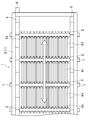
- Embodiment 1 and 2 show a panel storage cassette 1 according to Embodiment 1 of the present invention.
- This panel storage cassette 1 includes a plurality of types of panels P1 and P2 having different widths W1 and W2 (shown in FIG. 4). It can be inserted and stored from above.
- the panel storage cassette 1 includes a plurality of panel support members 2 divided into at least two (in this embodiment, two) groups each holding a plurality of panels P1 and P2.
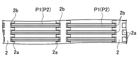
- the panel support member 2 extends in the vertical direction, and a large number of panel storage recesses 2 a for storing the panels P 1 and P 2 are formed side by side on the left and right sides. ing.
- the lower end of each panel P1, P2 contacts and is accommodated in the bottom wall 2b of the lower end of the panel support member 2.
- the plurality of panel support members 2 are supported by a frame body 3 having a rectangular parallelepiped frame structure and a rectangular frame shape so that the distance between the panel support members 2 can be changed while maintaining a parallel state to each other. Yes. And the some panel support member 2 is connected for every group by the some X-type link member 5 as a pitch change mechanism.
- One panel support member 2 in each group needs to be fixed to the frame body 3. For example, the panel support members 2 at both the left and right ends are fixed to the frame body 3.
- Each X-type link member 5 includes a pair of bar-shaped members 6 and a center pin 7 connected to the upper and lower middles of the panel support member 2, and each end of the adjacent bar-shaped members 6 is connected to each other by a connecting pin 8.
- the center pin 7 and the panel support member 2 are connected by fastening by cutting a screw at the tip of the center pin 7 and forming a screw hole in the panel support member 2.
- two groups of X-type link members 5 connected to the front and rear are provided.
- the upper end of the left and right outer X-type link member 5 is provided with an operation portion 9 extending to the left and right outer sides.
- each rod-like member 6 is rotated around the center pin 7, and the X-type link member 5 is expanded and contracted.
- the operation part 9 may be provided in the lower end part of the X-type link member 5, and may be provided in both upper and lower sides.
- the plurality of X-type link members 5 are provided with a link fixing mechanism 10 for fixing to the frame body 3 at the stage where the pitches are adjusted to the predetermined pitches x1 and x2.
- the link fixing mechanism 10 of the present embodiment includes a fixing plate 11 fixed to the front and rear surfaces of the frame 3.
- the fixed plate 11 has a slide groove 11a extending left and right, and the center pin 7 of each X-type link member 5 is supported by the slide groove 11a so as to be slidable. Since the outer diameter of the flange portion of the center pin 7 is larger than the inner diameter of the slide groove 11a, the center pin 7 is prevented from coming off.
- Each X-type link member 5 is fixed to the panel support member 2 by fastening the tip screw portion of the center pin 7 to the screw hole of the panel support member 2, and as a result, the panel support member 2 is fixed to the frame body 3.
- the pitches x1 and x2 between the center pins 7 of the two left and right groups are read to determine the pitches x1 and x2 as the widths W1 and W2 of the panels P1 and P2, respectively.
- the center pin 7 is fastened to the panel support member 2 so that the panel support members 2 of each group can be fixed. Since each panel support member 2 is connected to the X-type link member 5 using the center pin 7 of the X-type link member 5, the number of parts can be reduced.
- the center pin 7 When the panel support member 2 is slid, the center pin 7 is loosened to release the coupling with the fixing plate 11, and after the pitches x1 and x2 are determined, the center pin 7 is easily fixed to the fixing plate 11.
- the center pin 7 does not move with respect to the panel support member 2, it is not necessary to provide a long hole in the panel support member 2 for sliding the connecting pin 8 as in the modification described later, and the configuration is simple. Further, since there is no center pin 7 in the storage area of the panels P1 and P2, there is an advantage that there is no restriction on the height of the panels P1 and P2.
- the center pin 7 may be passed through the panel support member 2 back and forth and fixed from the inside with a fixing nut.
- the right operation portion 9 is lowered to extend the interval between the X-type link members 5.
- the connecting pins 8 of the respective X-type link members 5 move so as to approach each other, the angle between the pair of rod-shaped members 6 widens, and the pitch x1 between the panel support members 2 spreads equally. .
- the pitch x1 is easily confirmed by looking at the scale 11b of the fixed plate 11.
- each center pin 7 is fastened to the panel support member 2 and each center pin 7 is fixed to the fixing plate 11. Thereby, fixing of the panel support member 2 of the right group is completed.
- the left operation portion 9 is lowered to determine the pitch x2 in accordance with the width W2 of the other panel P2, and the X-type link member 5 is fixed to the fixing plate 11 in the same manner as the right side.
- each panel support member 2 can slide and move within the frame 3 at the same pitch x1, x2, so a dedicated jig or the like can be used.
- the pitches x1 and x2 between the panel support members 2 can be changed very easily.
- each panel support member 2 of each group is easily and reliably fixed at the same pitch x1, x2.
- each panel support member 2 of each group is securely fixed, it is possible to prevent the panels P1 and P2 accommodated between the panel support members 2 from dropping or wobbling.
- the panel storage cassette 1 is carried into the cleaning machine.
- a plurality of types of panels P1 and P2 can be stored in one panel storage cassette 1 by a simple method without using a dedicated jig, and washed together. It can be performed.
- FIG. 5 shows a modification of the present invention, which is different from the first embodiment in that the fixing method between the X-type link member 5 and the panel support member 2 is different.
- the same parts as those in FIGS. 1 to 4 are denoted by the same reference numerals, and detailed description thereof is omitted.
- each X-type link member 5 includes a pair of rod-shaped members 6 and a center pin 7 that rotatably supports the midpoint of each rod-shaped member 6.
- the center pin 7 extends in the front-rear direction and connects the front X-type link member 5 and the rear X-type link member 5.
- the panel support member 2 has a long hole 2c extending vertically, and each connecting pin 8 is connected to each panel support member 2 so as to be slidable.
- adjacent panel support members 2 are connected to each other by three pairs. Further, for example, the panel support members 2 at both the left and right ends are fixed to the frame body 3 via the fixing plates 11.
- a fixing nut 12 is provided on the back side of the X-type link member 5 on the side opposite to the flange portion of the center pin 7. By tightening the fixing nut 12, each X-type link member 5 is fixed to the fixing plate 11, and as a result, the panel support member 2 is fixed to the frame body 3.
- the connecting pin 8 is prevented from coming off from the panel support member 2.
- the connecting pin 8 since each panel support member 2 is connected to the X-type link member 5 using the connection pin 8, the number of parts can be reduced.
- FIG. 6 shows a second embodiment of the present invention, which is different from the first embodiment in that the link fixing mechanism 110 is different.
- the link fixing mechanism 110 includes a stopper 111 that extends in the vertical direction and is fixed to the left and right end portions of the frame 3 in place of the fixing plate 11.
- One end of a rod 112 is connected to the center pin 7 of the outermost X-type link member 5 on the left and right sides, and the other end of the rod 112 is set to the left and right with respect to a boss portion 111 a provided at the upper and lower intermediate portion of the stopper 111. It is slidably inserted.
- a nut 113 is rotatably inserted into the other end side of the rod 112.
- the rod 112 is provided with a scale 112a indicating the pitches x1 and x2 between the panel support members 2. Further, as in the first embodiment, the center pin 7 and the panel support member 2 are connected.
- the panel support members 2 at the left and right ends are fixed to the frame 3, so that the pitches x1 and x2 between the panel support members 2 are changed by rotating the nut 113, and the pitches x1 and x2 are changed.
- the X-type link member 5 is fixed while being held.
- each panel support member 2 of each group can be easily fixed at the same pitch x1 and x2. it can.
- the innermost X-type link member 5 on the left and right sides may be fixed to the frame 3 so that the pitches x1 and x2 can be changed.
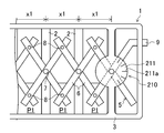
- FIG. 7 shows a third embodiment of the present invention, which differs from the first and second embodiments in that the link fixing mechanism 210 is different.
- the link fixing mechanism 210 of this embodiment includes an angle measuring device 211 that measures an angle formed by a pair of rod-like members 6 in the outermost X-type link member 5 for each group.
- the pitch x1, x2 between the panel support members 2 can be measured from the angle read from the angle measuring device 211 and the length of the rod-like member 6.
- the angle measuring device 211 is composed of a transparent disk fixed to the front and rear surfaces of the frame 3, and the angle measured by the angle measuring device 211 or a scale 211 a having pitches x 1 and x 2 converted from the angle is displayed on the panel. It is comprised so that the mark of the supporting member 2 may be match
- the center pin 7 can be fixed to the angle measuring device 211 fixed to the frame 3 with the pitches x1 and x2 being matched. Further, as in the first embodiment, the center pin 7 and the panel support member 2 are connected.
- each panel support member 2 of each group is easily fixed at the same pitch x1, x2. be able to.
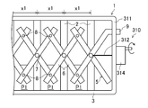
- FIG. 8 shows a fourth embodiment of the present invention, which differs from the first to third embodiments in that the link fixing mechanism 310 is different.
- a stopper 311 is provided outside the pair of end portions of the outermost X-type link member 5 for each group.
- one end of the wire 312 is connected to the center pin 7 of the outermost X-type link member 5.
- the other end of the wire 312 is connected to a wire winding device 314 so that the winding amount of the wire 312 can be measured.
- the pitches x1 and x2 are measured from the winding amount of the wire winding device 314. Further, as in the first embodiment, the center pin 7 and the panel support member 2 are connected.
- the panel support members 2 of each group can be easily fixed at the pitches x1 and x2 corresponding to the winding amount of the wire 312.
- one end of the wire 312 is not necessarily connected to the center pin 7 of the X-type link member 5 on the left and right outer sides.
- one end of the wire 312 may be connected to the outermost panel support member 2. Good.
- an elastic member such as a tension spring is provided at the other end of the wire 312 of the fourth embodiment, the tensile force of the elastic member is measured, and the pitches x1 and x2 are measured from the measured values. Also good.
- the present invention may be configured as follows with respect to the above embodiment.
- the center pin 7 is used to fix the panel support member 2, but it may be fixed with a string-like material such as a wire.
- the present invention is useful for a panel storage cassette that stores liquid crystal panels, liquid crystal substrates, plasma panels, and the like having a plurality of types of widths.
Landscapes
- Engineering & Computer Science (AREA)
- Mechanical Engineering (AREA)
- Packaging Frangible Articles (AREA)
- Bay Windows, Entrances, And Structural Adjustments Related Thereto (AREA)
Abstract
Description
異なる幅を有する複数種類のパネルを収納するためのパネル収納用カセットを対象とし、
上記パネル収納用カセットは、
少なくとも2以上のグループに分けられ、上記複数のパネルをそれぞれ保持する収納凹部が両側面に並んで形成された複数のパネル支持部材と、
上記複数のパネル支持部材を互いに平行状態を保ったままスライド移動可能に支持する、直方体状の骨組み構造である枠体と、
上記複数のパネル支持部材を各グループごとに連結し、上記複数種類のパネルの幅に合わせて等間隔となるように上記複数のパネル支持部材を互いに平衡状態を保ったまま上記枠体内でスライド移動させるピッチ変更機構とを備えている。
上記ピッチ変更機構は、隣接する上記パネル支持部材を互いに連結する複数のX型リンク部材であり、
上記各X型リンク部材は、
1対の棒状部材と、
各棒状部材の中点を回転可能に支持する中心ピンとを備え、
隣接する上記棒状部材の端部が連結ピンで回転可能に連結されている。
上記連結ピンが、上記各パネル支持部材に対してスライド移動可能に連結されている。
上記中心ピンが、上記各パネル支持部材に対してスライド移動不能に連結されている。
上記複数のX型リンク部材をピッチを調整した状態で上記枠体に固定するリンク固定機構を備えている。
上記リンク固定機構は、上記枠体に固定され、上記X型リンク部材の中心ピンをスライド移動可能に支持し、該中心ピンを固定可能に構成された固定板を有し、該固定板には、目盛りが設けられている。
上記リンク固定機構は、
上記各グループごとの一番外側の上記X型リンク部材における1対の端部の外側に配置したストッパと、
上記X型リンク部材の中心ピンに連結されると共に、上記ストッパに挿通されたロッドと、
上記ロッドに回転可能に挿入されたナットとを備え、
上記ナットを回転させることで、上記ピッチを変更すると共に、該ピッチを保持したまま上記X型リンク部材を固定するように構成されている。
上記ロッドには、上記ピッチを示す目盛りが設けられている。
上記リンク固定機構は、
上記各グループごとの一番外側の上記X型リンク部材における上記1対の棒状部材で形成される角度を計測する角度計測器を備え、
該角度計測器により、上記各ピッチを測定可能に構成され、
上記測定された角度で上記リンク部材を固定可能に構成されている。
上記リンク固定機構は、
上記各グループごとの一番外側の上記X型リンク部材における1対の端部の外側に配置したストッパと、
上記一番外側のX型リンク部材の中心ピンに一端が連結されたワイヤーと、
上記ワイヤーを巻き取るワイヤー巻取装置とを備え、
上記ワイヤー巻取装置の巻取量より上記ピッチを測定可能に構成され、
上記測定された巻取量で上記リンク部材を固定可能に構成されている。
上記リンク固定機構は、
上記各グループごとの一番外側の上記X型リンク部材における1対の端部の外側に配置したストッパと、
上記一番外側のX型リンク部材の中心ピンに一端が連結された弾性部材と、
上記弾性部材の他端を引っ張る張力を測定する荷重計とを備え、
上記荷重計より上記ピッチを測定可能に構成され、
上記測定された張力で上記リンク部材を固定可能に構成されている。
図1及び図2は本発明の実施形態1のパネル収納用カセット1を示し、このパネル収納用カセット1は、異なる幅W1,W2(図4に示す)を有する複数種類のパネルP1,P2を上方向から挿入して収納可能に構成されている。
図5は本発明の変形例を示し、X型リンク部材5とパネル支持部材2との固定方法が異なる点で上記実施形態1と異なる。なお、本変形例及び以下の各実施形態では、図1~図4と同じ部分については同じ符号を付してその詳細な説明は省略する。
図6は本発明の実施形態2を示し、リンク固定機構110が異なる点で上記実施形態1と異なる。
図7は本発明の実施形態3を示し、リンク固定機構210が異なる点で上記実施形態1及び2と異なる。
図8は本発明の実施形態4を示し、リンク固定機構310が異なる点で上記実施形態1~3と異なる。
詳しくは図示しないが、上記実施形態4のワイヤー312の他端に引っ張りバネなどの弾性部材を設け、この弾性部材の引張力を測定し、この測定値からピッチx1,x2を計測するようにしてもよい。
本発明は、上記実施形態について、以下のような構成としてもよい。
2 パネル支持部材
2a パネル収納凹部
3 枠体
5 X型リンク部材(ピッチ変更機構)
6 棒状部材
7 中心ピン
8 連結ピン
10 リンク固定機構
11 固定板
11b 目盛り
P1,P2 パネル
x1,x2 ピッチ
110 リンク固定機構
111 ストッパ
112 ロッド
112a 目盛り
113 ナット
210 リンク固定機構
211 角度計測器
310 リンク固定機構
311 ストッパ
312 ワイヤー
314 ワイヤー巻取装置
Claims (11)
- 異なる幅を有する複数種類のパネルを収納するためのパネル収納用カセットであって、
少なくとも2以上のグループに分けられ、上記複数のパネルをそれぞれ保持する収納凹部が両側面に並んで形成された複数のパネル支持部材と、
上記複数のパネル支持部材を互いに平行状態を保ったままスライド移動可能に支持する、直方体状の骨組み構造である枠体と、
上記複数のパネル支持部材を各グループごとに連結し、上記複数種類のパネルの幅に合わせて等間隔となるように上記複数のパネル支持部材を互いに平衡状態を保ったまま上記枠体内でスライド移動させるピッチ変更機構とを備えている
ことを特徴とするパネル収納用カセット。 - 請求項1に記載のパネル収納用カセットにおいて、
上記ピッチ変更機構は、隣接する上記パネル支持部材を互いに連結する複数のX型リンク部材であり、
上記各X型リンク部材は、
1対の棒状部材と、
各棒状部材の中点を回転可能に支持する中心ピンとを備え、
隣接する上記棒状部材の端部が連結ピンで回転可能に連結されている
ことを特徴とするパネル収納用カセット。 - 請求項2に記載のパネル収納用カセットにおいて、
上記連結ピンが、上記各パネル支持部材に対してスライド移動可能に連結されている
ことを特徴とするパネル収納用カセット。 - 請求項2に記載のパネル収納用カセットにおいて、
上記中心ピンが、上記各パネル支持部材に対してスライド移動不能に連結されている
ことを特徴とするパネル収納用カセット。 - 請求項2乃至4のいずれか1つに記載のパネル収納用カセットにおいて、
上記複数のX型リンク部材をピッチを調整した状態で上記枠体に固定するリンク固定機構を備えている
ことを特徴とするパネル収納用カセット。 - 請求項5に記載のパネル収納用カセットにおいて、
上記リンク固定機構は、
上記枠体に固定され、上記X型リンク部材の中心ピンをスライド移動可能に支持し、該中心ピンを固定可能に構成された固定板を有し、
該固定板には、目盛りが設けられている
ことを特徴とするパネル収納用カセット。 - 請求項5に記載のパネル収納用カセットにおいて、
上記リンク固定機構は、
上記各グループごとの一番外側の上記X型リンク部材における1対の端部の外側に配置したストッパと、
上記X型リンク部材の中心ピンに連結されると共に、上記ストッパに挿通されたロッドと、
上記ロッドに回転可能に挿入されたナットとを備え、
上記ナットを回転させることで、上記ピッチを変更すると共に、該ピッチを保持したまま上記X型リンク部材を固定するように構成されている
ことを特徴とするパネル収納用カセット。 - 請求項7に記載のパネル収納用カセットにおいて、
上記ロッドには、上記ピッチを示す目盛りが設けられている
ことを特徴とするパネル収納用カセット。 - 請求項5に記載のパネル収納用カセットにおいて、
上記リンク固定機構は、
上記各グループごとの一番外側の上記X型リンク部材における上記1対の棒状部材で形成される角度を計測する角度計測器を備え、
該角度計測器により、上記各ピッチを測定可能に構成され、
上記測定された角度で上記リンク部材を固定可能に構成されている
ことを特徴とするパネル収納用カセット。 - 請求項5に記載のパネル収納用カセットにおいて、
上記リンク固定機構は、
上記各グループごとの一番外側の上記X型リンク部材における1対の端部の外側に配置したストッパと、
上記一番外側のX型リンク部材の中心ピンに一端が連結されたワイヤーと、
上記ワイヤーを巻き取るワイヤー巻取装置とを備え、
上記ワイヤー巻取装置の巻取量より上記ピッチを測定可能に構成され、
上記測定された巻取量で上記リンク部材を固定可能に構成されている
ことを特徴とするパネル収納用カセット。 - 請求項5に記載のパネル収納用カセットにおいて、
上記リンク固定機構は、
上記各グループごとの一番外側の上記X型リンク部材における1対の端部の外側に配置したストッパと、
上記一番外側のX型リンク部材の中心ピンに一端が連結された弾性部材と、
上記弾性部材の他端を引っ張る張力を測定する荷重計とを備え、
上記荷重計より上記ピッチを測定可能に構成され、
上記測定された張力で上記リンク部材を固定可能に構成されている
ことを特徴とするパネル収納用カセット。
Priority Applications (2)
| Application Number | Priority Date | Filing Date | Title |
|---|---|---|---|
| CN201080034948.9A CN102470979B (zh) | 2009-09-03 | 2010-04-14 | 面板收纳用卡匣 |
| JP2011529769A JP5232921B2 (ja) | 2009-09-03 | 2010-04-14 | パネル収納用カセット |
Applications Claiming Priority (2)
| Application Number | Priority Date | Filing Date | Title |
|---|---|---|---|
| JP2009-203447 | 2009-09-03 | ||
| JP2009203447 | 2009-09-03 |
Publications (1)
| Publication Number | Publication Date |
|---|---|
| WO2011027488A1 true WO2011027488A1 (ja) | 2011-03-10 |
Family
ID=43649048
Family Applications (1)
| Application Number | Title | Priority Date | Filing Date |
|---|---|---|---|
| PCT/JP2010/002699 Ceased WO2011027488A1 (ja) | 2009-09-03 | 2010-04-14 | パネル収納用カセット |
Country Status (3)
| Country | Link |
|---|---|
| JP (1) | JP5232921B2 (ja) |
| CN (1) | CN102470979B (ja) |
| WO (1) | WO2011027488A1 (ja) |
Cited By (3)
| Publication number | Priority date | Publication date | Assignee | Title |
|---|---|---|---|---|
| JP2014534409A (ja) * | 2011-09-09 | 2014-12-18 | ベンタナ メディカル システムズ, インコーポレイテッド | スライド移送装置 |
| CN108945810A (zh) * | 2018-07-26 | 2018-12-07 | 湖州圣远物流有限公司 | 一种新型玻璃运输箱 |
| CN117228129A (zh) * | 2023-10-29 | 2023-12-15 | 山东阳光博士太阳能工程有限公司 | 一种光伏板运输保护装置 |
Families Citing this family (1)
| Publication number | Priority date | Publication date | Assignee | Title |
|---|---|---|---|---|
| CN103350830B (zh) * | 2013-07-19 | 2015-05-27 | 深圳市华星光电技术有限公司 | 卡匣 |
Citations (4)
| Publication number | Priority date | Publication date | Assignee | Title |
|---|---|---|---|---|
| JPS61229336A (ja) * | 1985-04-03 | 1986-10-13 | Rohm Co Ltd | ウエハキヤリア |
| JPH0369684U (ja) * | 1989-11-14 | 1991-07-11 | ||
| JPH11130254A (ja) * | 1997-10-24 | 1999-05-18 | Sharp Corp | 基板搬送カセット |
| JP2001036267A (ja) * | 1999-07-16 | 2001-02-09 | Sharp Corp | 基板用カセット |
Family Cites Families (1)
| Publication number | Priority date | Publication date | Assignee | Title |
|---|---|---|---|---|
| CN2269377Y (zh) * | 1996-12-08 | 1997-12-03 | 顺德卡斯华电器制造有限公司 | 激光光盘储存箱 |
-
2010
- 2010-04-14 CN CN201080034948.9A patent/CN102470979B/zh not_active Expired - Fee Related
- 2010-04-14 WO PCT/JP2010/002699 patent/WO2011027488A1/ja not_active Ceased
- 2010-04-14 JP JP2011529769A patent/JP5232921B2/ja active Active
Patent Citations (4)
| Publication number | Priority date | Publication date | Assignee | Title |
|---|---|---|---|---|
| JPS61229336A (ja) * | 1985-04-03 | 1986-10-13 | Rohm Co Ltd | ウエハキヤリア |
| JPH0369684U (ja) * | 1989-11-14 | 1991-07-11 | ||
| JPH11130254A (ja) * | 1997-10-24 | 1999-05-18 | Sharp Corp | 基板搬送カセット |
| JP2001036267A (ja) * | 1999-07-16 | 2001-02-09 | Sharp Corp | 基板用カセット |
Cited By (4)
| Publication number | Priority date | Publication date | Assignee | Title |
|---|---|---|---|---|
| JP2014534409A (ja) * | 2011-09-09 | 2014-12-18 | ベンタナ メディカル システムズ, インコーポレイテッド | スライド移送装置 |
| US9192935B2 (en) | 2011-09-09 | 2015-11-24 | Ventana Medical Systems, Inc. | Slide transfer device |
| CN108945810A (zh) * | 2018-07-26 | 2018-12-07 | 湖州圣远物流有限公司 | 一种新型玻璃运输箱 |
| CN117228129A (zh) * | 2023-10-29 | 2023-12-15 | 山东阳光博士太阳能工程有限公司 | 一种光伏板运输保护装置 |
Also Published As
| Publication number | Publication date |
|---|---|
| JPWO2011027488A1 (ja) | 2013-01-31 |
| CN102470979A (zh) | 2012-05-23 |
| JP5232921B2 (ja) | 2013-07-10 |
| CN102470979B (zh) | 2013-08-28 |
Similar Documents
| Publication | Publication Date | Title |
|---|---|---|
| JP5232921B2 (ja) | パネル収納用カセット | |
| US9235239B2 (en) | Flexible display with display support | |
| KR101252034B1 (ko) | 유리기판 적재용 카세트 | |
| US8234805B2 (en) | Sign fixture | |
| KR102233107B1 (ko) | 스트레쳐블 패널 양방향 평가장치 | |
| KR101435735B1 (ko) | 진열용 선반 | |
| US10606110B2 (en) | Display panel bracket | |
| KR200327237Y1 (ko) | 쇼케이스용 선반 | |
| US9056713B2 (en) | Cartridge for glass substrate | |
| CN210556409U (zh) | 防震抗压型lcd吸塑包装盘 | |
| JP3911284B1 (ja) | ガラス基板の熱処理装置 | |
| KR101480148B1 (ko) | 광학 측정 장치 | |
| KR101388875B1 (ko) | 단차 측정 기구 | |
| KR20120016746A (ko) | 유리기판 식각용 카세트 | |
| CN103453814B (zh) | 辅助校准装置 | |
| CN208537019U (zh) | 一种用于力学仪器的计量校准装置 | |
| JP5583516B2 (ja) | ワーク積載装置 | |
| JP2010521252A (ja) | プレートテンション棚 | |
| JP2010258269A (ja) | 高密度基板収納装置 | |
| KR20080005868U (ko) | 슬라이딩 랙용 플라콘 지지금구 | |
| JP2012209368A (ja) | キャビネット列連結構造 | |
| CN108125422A (zh) | 置物架及储藏柜用置物架 | |
| CN221656608U (zh) | 一种药品稳定性试验箱 | |
| RU128463U1 (ru) | Кассетница для матрасов | |
| JPH08173283A (ja) | 陳列棚装置 |
Legal Events
| Date | Code | Title | Description |
|---|---|---|---|
| WWE | Wipo information: entry into national phase |
Ref document number: 201080034948.9 Country of ref document: CN |
|
| 121 | Ep: the epo has been informed by wipo that ep was designated in this application |
Ref document number: 10813443 Country of ref document: EP Kind code of ref document: A1 |
|
| WWE | Wipo information: entry into national phase |
Ref document number: 2011529769 Country of ref document: JP |
|
| NENP | Non-entry into the national phase |
Ref country code: DE |
|
| 122 | Ep: pct application non-entry in european phase |
Ref document number: 10813443 Country of ref document: EP Kind code of ref document: A1 |