WO2011024793A1 - pHまたは濃度の測定装置及びpHまたは濃度の測定方法 - Google Patents
pHまたは濃度の測定装置及びpHまたは濃度の測定方法 Download PDFInfo
- Publication number
- WO2011024793A1 WO2011024793A1 PCT/JP2010/064257 JP2010064257W WO2011024793A1 WO 2011024793 A1 WO2011024793 A1 WO 2011024793A1 JP 2010064257 W JP2010064257 W JP 2010064257W WO 2011024793 A1 WO2011024793 A1 WO 2011024793A1
- Authority
- WO
- WIPO (PCT)
- Prior art keywords
- solution
- sensor
- concentration
- test tube
- baseline
- Prior art date
- Legal status (The legal status is an assumption and is not a legal conclusion. Google has not performed a legal analysis and makes no representation as to the accuracy of the status listed.)
- Ceased
Links
Images



Classifications
-
- G—PHYSICS
- G01—MEASURING; TESTING
- G01N—INVESTIGATING OR ANALYSING MATERIALS BY DETERMINING THEIR CHEMICAL OR PHYSICAL PROPERTIES
- G01N27/00—Investigating or analysing materials by the use of electric, electrochemical, or magnetic means
- G01N27/26—Investigating or analysing materials by the use of electric, electrochemical, or magnetic means by investigating electrochemical variables; by using electrolysis or electrophoresis
- G01N27/416—Systems
- G01N27/4166—Systems measuring a particular property of an electrolyte
- G01N27/4167—Systems measuring a particular property of an electrolyte pH
-
- G—PHYSICS
- G01—MEASURING; TESTING
- G01N—INVESTIGATING OR ANALYSING MATERIALS BY DETERMINING THEIR CHEMICAL OR PHYSICAL PROPERTIES
- G01N27/00—Investigating or analysing materials by the use of electric, electrochemical, or magnetic means
- G01N27/26—Investigating or analysing materials by the use of electric, electrochemical, or magnetic means by investigating electrochemical variables; by using electrolysis or electrophoresis
- G01N27/403—Cells and electrode assemblies
- G01N27/414—Ion-sensitive or chemical field-effect transistors, i.e. ISFETS or CHEMFETS
Definitions
- the present invention relates to a pH or concentration measuring device and a pH or concentration measuring method.
- ISFET Ion Sensitive FET
- FET Field Effect transistor
- a tantalum oxide (Ta 2 O 5 ) film or the like is used as a sensitive film so that hydrogen ions in a liquid can be detected and function as a pH sensor (for example, see Patent Document 1). .) Further, various ions can be detected by appropriately adjusting the material of the sensitive film, and it is often used as a concentration detection sensor or the like.
- This automatic pH measurement apparatus includes a pH sensor for measurement, a pH sensor for reference, and a pH sensor probe provided with a pseudo-reference electrode at a predetermined position inside the measurement pH sensor, a reference pH sensor, Calibration is performed by immersing the pseudo-reference electrode in the baseline solution and detecting the baseline potential with each sensor, and then the sample solution of the sample is aspirated into the pH sensor probe, thereby the measurement pH sensor is placed in the sample solution.
- the pH is measurable by detecting the hydrogen ion concentration by detecting the electric potential by contacting it.
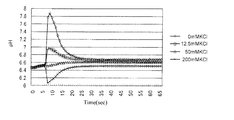
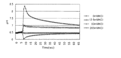
- the pH sensor for measurement is composed of ISFET, for example, when measuring the pH of a low solution having a pH buffering capacity of 0.2 mM / pH or less, measurement is started as shown in FIG. As a result, a large overshoot potential is generated between the measurement pH sensor and the reference pH sensor, and much time is required for the return. Therefore, the measured value of pH calculated using the final output at the time of 65 seconds contained a large error of 0.12 to 0.394 pH in absolute value.
- the measurement is started after 6 seconds, which is a time lag from when the sample solution of the subject is sucked into the pH sensor probe and comes into contact with the measurement pH sensor.
- a potassium chloride solution having a predetermined concentration is used as the sample solution.
- each sample solution contains 26 ⁇ M monopotassium phosphate, 108 ⁇ M dipotassium phosphate, and a low concentration of phosphate, so that the pH is 6.5 to 6.6 and the buffer capacity is 0.
- the solution has a low buffer capacity of about 06 mM / pH.
- the present inventors have conducted research and development to make it possible to measure even a low-buffering specimen in as short a time as possible, and have achieved the present invention.
- the pH or concentration measuring apparatus includes first and second sensors each configured by an ISFET, and a first reservoir for storing a sample solution as a specimen on the distal end side and a baseline on the proximal end side.
- a test tube having a second reservoir for storing the solution, a feeding means for feeding the baseline solution from the proximal end side of the test tube into the test tube, and an injection for injecting the sample solution into the first reservoir of the test tube
- a first sensor is provided as a sensor for measurement in the first reservoir, and a second sensor is provided as a reference sensor in the second reservoir, and is fed by the feeding means.
- the specimen solution is injected into the first reservoir by the injection means, thereby bringing the specimen solution into contact with the first sensor while bringing the baseline solution into contact with the second sensor.
- Specimen In the pH or concentration measuring device for measuring the pH or concentration of the liquid, there is provided a vibrating means for vibrating the interface between the sample solution and the baseline solution formed in the test tube by injecting the sample solution into the first reservoir. It was.
- the pH or concentration measuring apparatus of the present invention is characterized in that the interface solution is vibrated by applying pressure fluctuation to the baseline solution stored in the second reservoir by the vibrating means. It is also characterized in that the interface of the baseline solution is vibrated for 0.1 to 60 seconds at a frequency of 0.1 Hz or more.
- the first sensor out of the first and second sensors each composed of an ISFET is brought into contact with the analyte solution as the analyte, while the second sensor is based on the second sensor.
- a pH or concentration measurement method for measuring the pH or concentration of a sample solution by contacting a line solution, a first reservoir in which a first sensor is disposed and a second reservoir in which the second sensor is disposed. After supplying the baseline solution into the test tube provided with the section, the sample solution is injected into the first reservoir to form an interface between the sample solution and the baseline solution in the test tube, and this interface is vibrated. Measure after.
- the measuring apparatus and the measuring method for measuring the pH or concentration of the sample solution using the first sensor that is brought into contact with the sample solution and the second sensor that is brought into contact with the baseline solution they are brought into contact with each other.
- the overshoot potential generated between the first sensor and the second sensor can be converged in a short time by vibrating the interface between the analyte solution and the baseline solution formed by The concentration can be measured quickly. Therefore, it is possible to provide a measuring apparatus and a measuring method that can measure pH or concentration in a short time.
- the pH or concentration measuring apparatus and the pH or concentration measuring method according to the present invention use the first and second sensors that output signals corresponding to the pH or concentration of the solution, and the first sensor is the subject. While contacting with the sample solution, the second sensor is brought into contact with the baseline solution, and the pH or concentration is measured using signals output from the first and second sensors, respectively.
- the interface between the sample solution and the baseline solution formed when the sample solution is brought into contact with the first sensor is subjected to appropriate vibration. It is vibrated by means.
- the present inventors thus converge the overshoot potential generated between the first sensor and the second sensor in a short time by vibrating the interface between the sample solution and the baseline solution by the vibration means. This makes it possible to measure in a short time.
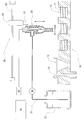
- FIG. 1 is a schematic diagram of a measuring apparatus according to the present embodiment.
- the measurement apparatus of the present embodiment is an automatic pH measurement apparatus, and includes a sample plate 10 having a plurality of sample wells 12 in which sample solutions 11 are stored, and a tip portion immersed in each sample solution 11.
- a test tube 20 serving as a probe for measuring pH
- a pump 30 for feeding a baseline solution from a solution tank 32 through a feed pipe 31 into the test tube 20, and a test tube 20 as will be described later
- a drive circuit 40 that supplies a drive voltage and detects a signal for detecting pH using each sensor and electrode provided in the sensor, an analysis device 50 that analyzes a signal detected by the drive circuit 40, and a test tube 20 It is comprised with the moving mechanism 60 which moves.
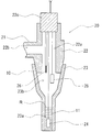
- the inspection tube 20 includes a first base 22 having a connection portion 21 to which one end of a supply pipe 31 is connected, and a base end side detachably attached to the first base 22 and a distal end side.
- a cylindrical second base 23 having a diameter smaller than that of the base end and tapered as a whole, and a pH sensor for measurement which is a first sensor provided near the tip of the second base 23 inside the second base 23 24, a reference pH sensor 25 that is a second sensor provided inside the first base 22, and a pseudo comparison electrode 26 provided in the vicinity of the reference pH sensor 25.
- the measurement pH sensor 24 and the reference pH sensor 25 are largely drawn for convenience of explanation, but in the implementation, the measurement pH sensor 24 and the reference pH sensor 25 are about 0.5 mm wide. This is a very small sensor, and a commercially available pH-ISFET is used.
- the first base 22 is provided with a first flow path 22a penetrating in the vertical direction, and one end of the first base 22 is connected to the first flow path 22a through the connecting portion 21 and the other end is connected to the supply pipe 31.
- a second flow path 22b to be connected in communication is provided, and the baseline solution supplied from the supply pipe 31 is guided from the second flow path 22b to the first flow path 22a.
- the first base 22 is provided with a closing body 22c at the upper opening of the first flow path 22a to form a substantially L-shaped flow path.
- the second base 23 is detachably attached by screwing the base end side to the first base 22, and is connected in communication with the lower opening of the first flow path 22a, and is guided to the first flow path 22a.
- a baseline solution is introduced into the second substrate 23.
- the baseline solution is stored in the second substrate 23.
- the aspirated sample is stored.
- a portion near the end where the pH sensor 24 for measurement is occupied by the solution is used as the first storage portion 23a, and a portion closer to the base end is used as the second storage portion 23b.
- the measurement pH sensor 24 and the reference pH sensor 25 constituted by pH-ISFETs are respectively attached to the closing body 22c in a suspended manner by wiring, and are arranged at predetermined positions by adjusting the length of the wiring. Yes.
- the pseudo comparison electrode 26 is also attached to the closing body 22c in a suspended manner by a predetermined wiring, and is arranged in the vicinity of the reference pH sensor 25 by adjusting the length of the wiring.
- the portion near the base end of the second base 23 is used as the second storage portion 23b, but the inside of the first base 22 may be used as the second storage portion.
- the reference pH sensor 25 and the pseudo comparison electrode 26 are arranged on the downstream side of the second flow path 22b so as to be surely immersed in the baseline solution.
- Each wiring drawn out from the test tube 20 via the closing body 22c is connected to the drive circuit 40.
- the drive circuit 40 drives the measurement pH sensor 24 and the reference pH sensor 25, and the measurement pH sensor.
- the potential difference between the potentials of the reference voltage sensor 24 and the reference pH sensor 25 and the potential of the pseudo comparison electrode 26 is amplified as an output signal and input to the analysis device 50.
- the analysis device 50 is an electronic computer such as a personal computer, and measures the pH by analyzing the signal input from the drive circuit 40.
- the analysis device 50 performs drive control of the pump 30 that feeds the baseline solution to the test tube 20 and sucks the sample solution 11, and supplies the test tube 20 to the test tube 20 based on the control by the analysis device 50.
- a baseline solution is being delivered.
- the analysis apparatus 50 also controls a moving mechanism 60 that moves the test tube 20.
- the moving mechanism 60 moves the test tube 20 up and down and left and right to be stored in a predetermined sample well 12 of the sample plate 10.
- the pH of the sample solution 11 is sequentially measured.
- the moving mechanism 60 includes an actuator 62 that includes a rod 61 that moves forward and backward, and an XY table 63 that moves the actuator 62 in the horizontal direction.
- a test tube 20 is attached.
- the moving mechanism 60 may be in any form as long as the inspection tube 20 can be moved up and down and left and right.
- the sample plate 10 is provided with a plurality of sample wells 12, each of which contains different sample solutions 11 so that the test tube 20 is moved by the moving mechanism 60 and can be continuously measured.
- a drain well 13 for cleaning the tube 20 is provided.
- a sample tube may be used instead of the sample well 12 as a sample container for storing the sample solution, and a turntable may be used instead of the XY table as the moving mechanism.
- the baseline solution is sent out from the tip of the test tube 20, The test tube 20 and the measurement pH sensor 24 are washed with the baseline solution.
- the drain well 13 is provided with an overflow pipe 14 through which the baseline solution and each specimen solution overflowed from the drain well 13 are discharged.
- the test tube 20 is cleaned with the drainage well 13 as a cleaning step.
- the inside of the test tube 20 is filled with the baseline solution, and the measurement pH sensor 24 and the reference pH sensor 25 both come into contact with the baseline solution and each output a predetermined signal. Zero signal calibration is performed using this signal.
- the sample solution adhering to the outer wall of the tip of the test tube 20 is also washed.
- the measuring apparatus moves the test tube 20 above the predetermined sample well 12 by the moving mechanism 60 and lowers the test tube 20 to move the test tube 20 as shown in FIG.
- the tip of 20 is immersed in a predetermined sample solution 11, and the pump 30 is driven in reverse in this state to reversely flow the baseline solution in the test tube 20, and as shown in FIG.
- the sample solution 11 is sucked into the first reservoir 23a, and the sample solution 11 is brought into contact with the measurement pH sensor 24.
- the forward rotation drive and the reverse rotation drive of the pump 30 are alternately repeated, so that the baseline solution in the test tube 20 and the sample in the first reservoir 23a are shown in FIG.
- the interface R formed by the solution 11 is vibrated as indicated by an arrow. That is, in the present embodiment, the pump 30 is used as a vibration unit that vibrates the interface R.
- the pump 30 of the vibration means applies pressure fluctuations to the baseline solution in the second reservoir 23b of the test tube 20 by alternately repeating forward rotation driving and reverse rotation driving. R can be vibrated.
- the measurement pH sensor 24 is always in contact with the sample solution 11 during the vibration of the interface R, and the reference pH sensor 25 is always in contact with the baseline solution. The positions of the pH sensor 24 and the reference pH sensor 25 are not exceeded.
- the interface R oscillates between the measurement pH sensor 24 and the reference pH sensor 25 with an amplitude within about 10% of the distance between the measurement pH sensor 24 and the reference pH sensor 25. It is desirable to make it.
- the frequency of the oscillating interface R may be a frequency of 0.1 Hz or more, and preferably a frequency of about 1 to 100 Hz.
- the vibration time may be about 0.1 to 60 seconds. In the present embodiment, after the sample solution 11 is sucked into the first reservoir 23a, the sample solution 11 is vibrated at about 2.0 Hz for about 30 seconds.
- the sample solution 11 is a potassium chloride solution having a predetermined concentration similar to the measurement result shown in FIG.
- the absolute value of the pH measurement error in this case was 0.010 to 0.060 pH, which was greatly improved compared to the case of FIG.
- the pump 30 may be expensive because the pump 30 needs to be driven and controlled with high accuracy.
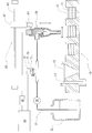
- a vibration mechanism 70 for vibrating the interface R may be provided in the supply pipe 31 on the downstream side of the pump 30.
- the vibration mechanism 70 of the present embodiment includes a cylinder 71 whose tip is connected to the feed pipe 31, a piston 72 provided in the cylinder 71, and an actuator 73 that drives the piston 72 forward and backward.
- the vibration mechanism 70 may also be used for aspirating the sample solution 11. That is, the actuator 73 is driven and controlled by the analysis device 50. The piston 72 is moved forward during the cleaning step, and the piston 72 is moved backward during the measurement step. The sample solution 11 is aspirated into the reservoir 23a.
- the amount of the sample solution 11 sucked into the first reservoir 23a can be adjusted by the retraction amount of the piston 72. More accurate control is possible.
- the actuator 73 vibrates the piston 72 with a predetermined amplitude and a predetermined frequency for a predetermined time, thereby applying a predetermined pressure fluctuation to the baseline solution stored in the second storage portion 23b, and the sample solution 11 and the baseline.
- the interface R with the solution can be vibrated.
- the vibration mechanism 70 By providing the vibration mechanism 70 in this way, it is easy to control the vibration of the interface R, and the pump 30 only needs to push the baseline solution in only one direction, so that an inexpensive pump can be used and the measuring apparatus can be made inexpensive. Can do.
- the vibration mechanism 70 is not limited to the above-described form including the cylinder 71, the piston 72, and the actuator 73, and applies a predetermined pressure fluctuation to the baseline solution stored in the second storage portion 23b. If it can, it can be set as a suitable form.
- a part of the supply pipe 31 that supplies the baseline solution is constituted by a flexible rubber pipe 81, and is arranged with the rubber pipe 81 interposed therebetween. It is good also as a vibration mechanism by providing the cams 82 and 82 for narrowing which narrows the rubber tube 81 intermittently.
- this vibration mechanism is provided with a drive motor that rotationally drives each constriction cam 82, and is driven and controlled by the analysis device 50.
- the two stenosis cams 82 are rotated in the opposite directions.
- the stenosis cam 82 is provided with a plurality of bulged convex portions 82a at predetermined intervals on the circumferential outer periphery, and the stenosis cam 82 is rotated.
- the rubber tube 81 is narrowed by the convex portion 82a.
- the two constricting cams 82 and 82 arranged to face each other with the rubber tube 81 interposed therebetween synchronize the positions of the convex portions 82a so that the convex portions 82a are pressed against the rubber tube 81 at the same time.
- a part of the supply pipe 31 is constituted by the rubber tube 81, and by narrowing the rubber tube 81, pressure fluctuation is generated in the baseline solution in the rubber tube 81, and the sample solution 11 and the baseline solution are separated.
- the interface R is vibrated, it is possible to provide a vibration mechanism that can be stably operated without causing air entrapment in the vibration mechanism portion.
- the pH measurement device using the pH-ISFET is used for the measurement pH sensor 24 and the reference pH sensor 25.
- the measurement pH sensor and the reference pH sensor capable of measuring a predetermined concentration are used.
- a concentration measuring device can be obtained.
- the present invention can be widely applied to measuring devices for pH or concentration of various solutions.
Landscapes
- Chemical & Material Sciences (AREA)
- Life Sciences & Earth Sciences (AREA)
- Health & Medical Sciences (AREA)
- Physics & Mathematics (AREA)
- Chemical Kinetics & Catalysis (AREA)
- Electrochemistry (AREA)
- Molecular Biology (AREA)
- Analytical Chemistry (AREA)
- Biochemistry (AREA)
- General Health & Medical Sciences (AREA)
- General Physics & Mathematics (AREA)
- Immunology (AREA)
- Pathology (AREA)
- Investigating Or Analyzing Materials By The Use Of Electric Means (AREA)
- Sampling And Sample Adjustment (AREA)
Abstract
【課題】低緩衝能の被検体においてもできるだけ短時間で測定可能なpHまたは濃度の測定装置及びpHまたは濃度の測定方法を提供する。 【解決手段】溶液のpHまたは濃度に応じた信号を出力する第1と第2のセンサと、第1のセンサが配設された第1貯留部及び第2のセンサが配設された第2貯留部とが設けられた検査管と、検査管内にベースライン溶液を送給する送給手段と、検査管の第1貯留部内に被検体である検体溶液を注入して第1のセンサに検体溶液に接触させる注入手段とを備えて、検体溶液のpHまたは濃度を測定するpHまたは濃度の測定装置及び測定方法において、第1貯留部内に貯留した検体溶液とベースライン溶液との界面を振動させる振動手段を設ける。
Description
本発明は、pHまたは濃度の測定装置及びpHまたは濃度の測定方法に関するものである。
従来、半導体材料を用いて構成した電界効果トランジスタ(FET:Field Effect Transistor)のゲート部分に所定の感応膜を設けたISFET(Ion Sensitive FET)が知られている。このISFETでは、感応膜が所定のイオンと反応することによって生じた電位変動を検出可能としている。
このようなISFETにおいて、感応膜に酸化タンタル(Ta2O5)膜などを用いることにより液体中の水素イオンを検出可能としてpHセンサとして機能するものが知られている(例えば、特許文献1参照。)。また、感応膜の材質を適宜調整することによって各種のイオンを検出することができ、濃度検出用のセンサなどとして用いられることも多い。
そして、上記したpHセンサを用いて液体のpHを自動測定する装置が提案されている(例えば、特許文献2参照。)。
このpH自動測定装置では、測定用pHセンサと、参照用pHセンサと、擬似比較電極を内部の所定位置に設けたpHセンサプローブを備えており、測定用pHセンサと、参照用pHセンサと、擬似比較電極をベースライン溶液に浸漬させて各センサでベースライン電位を検出することにより校正を行い、その後、pHセンサプローブ内に被検体の検体溶液を吸引することにより測定用pHセンサを検体溶液に接触させて電位を検出することにより水素イオン濃度を検出して、pHを測定可能としている。
しかしながら、測定用pHセンサをISFETで構成している場合には、たとえばpH緩衝能が0.2mM/pH以下のような低い溶液のpHを測定する際に、図8に示すように、測定開始にともなって測定用pHセンサと参照用pHセンサとの間において大きなオーバーシュート電位が発生し、しかも、その復帰に多大な時間を要することとなっていた。そのため、65秒の時点における最終出力を用いて算出したpHの測定値は、誤差の絶対値で0.12~0.394pHという大きな誤差を含むこととなっていた。
特に、このオーバーシュート電位が解消されるまでは、正確な測定をすることができないため、測定に要する時間が極めて長くなり、測定時間の短縮化が困難となっていた。なお、図8においては、被検体の検体溶液がpHセンサプローブ内に吸引されて測定用pHセンサに接触するまでのタイムラグである6秒間の後、測定が開始されている。また、この場合、検体溶液には所定濃度とした塩化カリウム溶液を用いている。特に、各検体溶液は、26μMリン酸一カリウムと、108μMリン酸二カリウムと、低濃度のリン酸塩を含んでおり、これによりpHが6.5~6.6で、緩衝能が0.06mM/pH程度の低緩衝能溶液となっている。
本発明者らはこのような現状に鑑み、低緩衝能の被検体においてもできるだけ短時間で測定可能とすべく研究開発を行って、本発明を成すに至ったものである。
本発明のpHまたは濃度の測定装置では、それぞれISFETで構成した第1と第2のセンサと、先端側に被検体である検体溶液を貯留する第1貯留部を有するとともに基端側にベースライン溶液を貯留する第2貯留部を有する検査管と、検査管の基端側から検査管内にベースライン溶液を送給する送給手段と、検査管の第1貯留部内に検体溶液を注入する注入手段とを備えて、第1貯留部には第1のセンサを測定用のセンサとして設けるとともに、第2貯留部には第2のセンサを参照用のセンサとして設け、送給手段で送給したベースライン溶液により検査管内を洗浄した後に、注入手段で第1貯留部内に検体溶液を注入することにより、第1のセンサに検体溶液を接触させる一方で第2のセンサにベースライン溶液を接触させて、検体溶液のpHまたは濃度を測定するpHまたは濃度の測定装置において、第1貯留部内に検体溶液を注入したことにより検査管内に形成される検体溶液とベースライン溶液との界面を振動させる振動手段を設けた。
さらに、本発明のpHまたは濃度の測定装置では、振動手段によって第2貯留部内に貯留したベースライン溶液に圧力変動を加えて界面を振動させることにも特徴を有し、振動手段によって検体溶液とベースライン溶液の界面を0.1Hz以上の周波数で、0.1~60秒間振動させることにも特徴を有するものである。
また、本発明のpHまたは濃度の測定方法では、それぞれISFETで構成した第1と第2のセンサのうち、第1のセンサに被検体である検体溶液を接触させる一方、第2のセンサにベースライン溶液を接触させて検体溶液のpHまたは濃度を測定するpHまたは濃度の測定方法において、第1のセンサが配設される第1貯留部と前記第2のセンサが配設される第2貯留部とを設けた検査管内にベースライン溶液を送給した後に、第1貯留部内に検体溶液を注入することにより検査管内に検体溶液とベースライン溶液との界面を形成し、この界面を振動させた後に測定するものである。
本発明によれば、検体溶液に接触させる第1のセンサと、ベースライン溶液に接触させる第2のセンサとを用いて検体溶液のpHまたは濃度を測定する測定装置及び測定方法において、互いに接触させることにより形成される検体溶液とベースライン溶液との界面を振動させることにより、第1のセンサと第2のセンサとの間において生じたオーバーシュート電位を短時間で収束させることができ、pHまたは濃度の測定を速やかに行うことができる。したがって、短時間でpHまたは濃度を測定可能とした測定装置及び測定方法を提供できる。
10 検体プレート
11 検体溶液
12 検体ウェル
13 排液ウェル
14 オーバーフロー管
20 検査管
21 接続部
22 第1基体
22a 第1流路
22b 第2流路
22c 閉塞体
23 第2基体
23a 第1貯留部
23b 第2貯留部
24 測定用pHセンサ
25 参照用pHセンサ
26 擬似比較電極
30 ポンプ
31 送給配管
32 溶液タンク
40 駆動回路
50 解析装置
60 移動機構
61 ロッド
62 アクチュエータ
63 X-Yテーブル
70 振動機構
71 シリンダ
72 ピストン
73 アクチュエータ
R 界面
11 検体溶液
12 検体ウェル
13 排液ウェル
14 オーバーフロー管
20 検査管
21 接続部
22 第1基体
22a 第1流路
22b 第2流路
22c 閉塞体
23 第2基体
23a 第1貯留部
23b 第2貯留部
24 測定用pHセンサ
25 参照用pHセンサ
26 擬似比較電極
30 ポンプ
31 送給配管
32 溶液タンク
40 駆動回路
50 解析装置
60 移動機構
61 ロッド
62 アクチュエータ
63 X-Yテーブル
70 振動機構
71 シリンダ
72 ピストン
73 アクチュエータ
R 界面
本発明のpHまたは濃度の測定装置及びpHまたは濃度の測定方法は、溶液のpHまたは濃度に応じた信号を出力する第1と第2のセンサを用いるとともに、第1のセンサを被検体である検体溶液に接触させる一方、第2のセンサをベースライン溶液に接触させて、第1と第2のセンサからそれぞれ出力された信号を用いてpHまたは濃度を測定するものである。
特に、本発明のpHまたは濃度の測定装置及びpHまたは濃度の測定方法では、第1のセンサに検体溶液を接触させた際に形成される検体溶液とベースライン溶液との界面を、適宜の振動手段によって振動させているものである。
本発明者らは、このように振動手段によって検体溶液とベースライン溶液との界面を振動させることによって、第1のセンサと第2のセンサとの間において生じたオーバーシュート電位を短時間で収束させることを知見し、短時間での測定を可能としているものである。
以下において、図面に基づいて本発明の実施形態を詳説する。図1は、本実施形態の測定装置の概略模式図である。
本実施形態の測定装置は、pHの自動測定装置であって、検体溶液11がそれぞれ貯留される複数個の検体ウェル12を備えた検体プレート10と、各検体溶液11に先端部を浸漬させてpHを測定するプローブとなっている検査管20と、この検査管20内に送給配管31を介して溶液タンク32からベースライン溶液を送給するポンプ30と、後述するように検査管20内に設けた各センサ及び電極を用いてpHを検出するための駆動電圧の供給及び信号検出を行う駆動回路40と、この駆動回路40で検出された信号を解析する解析装置50と、検査管20を移動操作する移動機構60とで構成している。
検査管20は、図2に示すように、送給配管31の一端が接続される接続部21を有する第1基体22と、この第1基体22に基端側を着脱自在に取り付けるとともに先端側を基端側よりも小径として全体として先細り状とした円筒状の第2基体23と、第2基体23の内側で第2基体23の先端寄りに設けた第1のセンサである測定用pHセンサ24と、第1基体22の内側に設けた第2のセンサである参照用pHセンサ25と、参照用pHセンサ25の近傍に設けた擬似比較電極26とで構成している。
図1及び図2では、説明の便宜上、測定用pHセンサ24及び参照用pHセンサ25を大きく描いているが、実施には、測定用pHセンサ24及び参照用pHセンサ25は0.5mm幅程度の極めて微少なセンサであり、市販のpH-ISFETを用いている。
第1基体22には、上下方向に貫通させて設けた第1流路22aと、接続部21部分を貫通して一端を第1流路22aに連通連結するとともに他端を送給配管31に連通連結させる第2流路22bを設けており、送給配管31から送給されたベースライン溶液を第2流路22bから第1流路22aに導いている。
第1基体22には、第1流路22aにおける上部の開口部分に閉塞体22cを装着し、実質的にL字状の流路を形成している。
第2基体23は、基端側を第1基体22に螺着することにより着脱自在に取り付けて、第1流路22aの下部の開口部分と連通連結し、第1流路22aに導かれたベースライン溶液を第2基体23内に導いている。
特に、第2基体23は先細り状としているので、第2基体23内においてベースライン溶液が貯留されることとなっており、第2基体23では、検体溶液11を吸引した時、吸引された検体溶液によって占有され、かつその中に測定用pHセンサ24が設けられている端寄りの部分を第1貯留部23aとし、それよりも基端寄りの部分を第2貯留部23bとしている。
pH-ISFETで構成した測定用pHセンサ24及び参照用pHセンサ25は、それぞれ配線によって閉塞体22cに吊り下げ状に装着しており、配線の長さを調整することにより所定位置に配置している。
擬似比較電極26も所定の配線によって閉塞体22cに吊り下げ状に装着しており、配線の長さを調整することにより参照用pHセンサ25の近傍に配置している。
本実施形態では、第2基体23の基端寄りの部分を第2貯留部23bとしているが、第1基体22内を第2貯留部としてもよい。ただし、参照用pHセンサ25及び擬似比較電極26は、第2流路22bよりも下流側に配置することにより、ベースライン溶液中に確実に浸漬した状態となるようにしている。
閉塞体22cを介して検査管20から引き出された各配線は駆動回路40に接続しており、この駆動回路40によって測定用pHセンサ24及び参照用pHセンサ25を駆動させるとともに、測定用pHセンサ24及び参照用pHセンサ25のそれぞれの電位と擬似比較電極26の電位の電位差を出力信号として増幅して、解析装置50に入力している。
解析装置50は、本実施形態ではパーソナルコンピュータなどの電子計算機であって、駆動回路40から入力された信号を解析してpHを測定している。
また、解析装置50では、検査管20にベースライン溶液を送給したり、検体溶液11を吸引したりするポンプ30の駆動制御を行っており、解析装置50による制御に基づいて検査管20にベースライン溶液を送給している。
さらに、解析装置50では検査管20を移動操作する移動機構60も制御しており、移動機構60によって検査管20を上下左右に移動させて、検体プレート10の所定の検体ウェル12に貯留された検体溶液11のpHを順次測定している。
移動機構60は、本実施形態では、上下方向に進退するロッド61を備えたアクチュエータ62と、このアクチュエータ62を水平方向に移動させるX-Yテーブル63とで構成しており、ロッド61の先端に検査管20を装着している。なお、移動機構60は、検査管20を上下左右に移動させることができればどのような形態であってもよい。
検体プレート10には、複数個の検体ウェル12を設けており、異なる検体溶液11をそれぞれ収容して、移動機構60により検査管20を移動させながら連続的に測定できるようにしているとともに、検査管20の洗浄を行うための排液ウェル13を設けている。
なお、検体溶液を収容する検体容器としては、検体ウェル12の代わりにサンプルチューブを用いてもよく、また移動機構としては、X-Yテーブルの代わりにターンテーブルを用いてもよい。
なお、検体溶液を収容する検体容器としては、検体ウェル12の代わりにサンプルチューブを用いてもよく、また移動機構としては、X-Yテーブルの代わりにターンテーブルを用いてもよい。
排液ウェル13では、図3に示すように、排液ウェル13内に検査管20の先端を挿入した状態でポンプ30を駆動することにより、検査管20の先端からベースライン溶液を送り出して、検査管20及び測定用pHセンサ24をベースライン溶液で洗浄している。
排液ウェル13にはオーバーフロー管14を設けており、このオーバーフロー管14を介して排液ウェル13からオーバーフローさせたベースライン溶液及び各検体溶液を排出している。
このように構成した測定装置でpHの測定を行う場合には、まず、洗浄ステップとして排液ウェル13で検査管20を洗浄する。この洗浄ステップにおいて、検査管20内はベースライン溶液で満たされ、測定用pHセンサ24と参照用pHセンサ25は、ともにベースライン溶液と接触し、それぞれ所定の信号を出力することとなる。この信号を用いて零点校正を行っている。なお、この時、検査管20の先端部外壁に付着した検体溶液も洗浄される。
ついで、測定ステップとして、測定装置は、移動機構60によって検査管20を所定の検体ウェル12の上方に移動させるとともに、検査管20を降下させて、図4(a)に示すように、検査管20の先端を所定の検体溶液11に浸漬させ、その状態でポンプ30を逆転駆動させることにより検査管20のベースライン溶液を逆流させて、図4(b)に示すように、検査管20の第1貯留部23aに検体溶液11を吸引し、測定用pHセンサ24に検体溶液11を接触させている。
さらに、測定装置では、ポンプ30の正転駆動と逆転駆動とを交互に繰り返させることにより、図4(c)に示すように、検査管20内のベースライン溶液と第1貯留部23aの検体溶液11とによって形成されている界面Rを矢印のように振動させている。すなわち、本実施形態では、ポンプ30を、界面Rを振動させる振動手段として用いている。
特に、振動手段のポンプ30は、正転駆動と逆転駆動を交互に繰り返すことにより、検査管20の第2貯留部23bのベースライン溶液に圧力変動を加えているものであり、極めて容易に界面Rを振動させることができる。
界面Rを振動させる際には、界面Rの振動中に測定用pHセンサ24は常に検体溶液11と接触するとともに、参照用pHセンサ25は常にベースライン溶液と接触して、界面Rが測定用pHセンサ24及び参照用pHセンサ25の位置を超えないようにしている。
具体的には、界面Rは、測定用pHセンサ24と参照用pHセンサ25の間であって、測定用pHセンサ24と参照用pHセンサ25の間の距離の約10%以内の振幅で振動させることが望ましい。
この場合、界面Rの振動にともなって、界面R近傍の検体溶液11とベースライン溶液が撹乱されること、あるいは検体溶液11とベースライン溶液が混ざり合うことがオーバーシュート電位の解消のためには必要である。明確な界面を維持したままでの単なる振動、あるいは往復動はオーバーシュート電位の解消には有効ではない。
振動する界面Rの周波数は0.1Hz以上の周波数であればよく、好適には1~100Hz程度の周波数であればよい。また、振動時間は0.1~60秒間程度であればよい。本実施形態では、第1貯留部23aへの検体溶液11の吸引後、約2.0Hzで約30秒間振動させた。
図5に示すように、界面Rを振動させることにより、測定開始にともなって生じたオーバーシュート電位を短時間で収束させることができ、pHまたは濃度の測定を速やかに行うことができる。したがって、短時間でpHまたは濃度を測定可能とした測定装置及び測定方法を提供できる。なお、この場合でも検体溶液11には、図8に示した測定結果と同様の所定濃度とした塩化カリウム溶液を用いている。この場合のpHの測定誤差の絶対値は、0.010~0.060pHであって、図8の場合と比較して大幅に改善された。
上述したように界面Rの振動をポンプ30で行う場合には、ポンプ30を精度よく駆動制御する必要があるために、ポンプ30が高価となるおそれがある。
そこで、ポンプ30でベースライン溶液を往復させる代わりに、図6に示すように、ポンプ30の下流側の送給配管31に界面Rを振動させるための振動機構70を介設してもよい。
本実施形態の振動機構70では、先端を送給配管31に連通連結したシリンダ71と、このシリンダ71内に設けたピストン72と、このピストン72を進退駆動させるアクチュエータ73とで構成している。
この振動機構70は検体溶液11の吸引用として兼用してもよい。すなわち、アクチュエータ73は解析装置50で駆動制御しており、洗浄ステップの際にはピストン72を前進させた状態とし、測定ステップの際にはピストン72を後退させることにより、検査管20の第1貯留部23aに検体溶液11を吸引している。
このようにシリンダ71とピストン72を備えた振動機構70とした場合、ピストン72の後退量によって第1貯留部23aに吸引される検体溶液11の量を調整できるので、検体溶液11の吸引量をより正確に制御することができる。
さらに、アクチュエータ73によってピストン72を所定の振幅、及び所定の周波数で所定時間振動させることにより、第2貯留部内23bに貯留したベースライン溶液に所定の圧力変動を加えて、検体溶液11とベースライン溶液との界面Rを振動させることができる。
このように振動機構70を設けることにより界面Rの振動を制御しやすく、しかもポンプ30は一方向だけにベースライン溶液を押し流すだけでよいので安価なポンプを利用でき、測定装置を安価とすることができる。
なお、振動機構70は、上述したシリンダ71と、ピストン72と、アクチュエータ73とで構成する形態に限定するものではなく、第2貯留部内23bに貯留したベースライン溶液に所定の圧力変動を加えることができれば、適宜の形態とすることができる。
すなわち、たとえば図7に示すように、ベースライン溶液を送給している送給配管31の一部を、可撓性を有するゴム管81で構成するとともに、このゴム管81を挟んで配置さしてゴム管81を断続的に狭窄する狭窄用カム82,82を設けて、振動機構としてもよい。
図示しないが、この振動機構では、各狭窄用カム82をそれぞれ回転駆動させる駆動モータを設けており、解析装置50によって駆動制御している。2つの狭窄用カム82は互いに逆回転させることとしており、狭窄用カム82には円周状の外周縁に所定間隔で膨出状の凸部82aを複数設けて、狭窄用カム82を回転させることにより凸部82aでゴム管81を狭窄することとしている。
特に、ゴム管81を挟んで対向させて配置した2つの狭窄用カム82,82は、凸部82aをゴム管81に押しつける際に同時に押しつけるように各凸部82aの位置を同期させている。
このように送給配管31の一部をゴム管81で構成し、ゴム管81を狭窄することによりゴム管81内のベースライン溶液に圧力変動を生じさせて検体溶液11とベースライン溶液との界面Rを振動させた場合には、振動機構部分において空気のかみ込みを生じさせにくく、安定的に動作可能な振動機構とすることができる。
上述した実施形態では、測定用pHセンサ24及び参照用pHセンサ25にpH-ISFETを用いたpH測定装置としているが、所定の濃度を測定可能とした測定用pHセンサ及び参照用pHセンサを用いることにより、濃度測定装置とすることもできる。
本発明は、各種溶液のpHまたは濃度の測定装置に広く適用することができる。
Claims (4)
- それぞれISFETで構成した第1と第2のセンサと、
先端側に被検体である検体溶液を貯留する第1貯留部を有するとともに基端側にベースライン溶液を貯留する第2貯留部を有する検査管と、
前記検査管の基端側から前記検査管内に前記ベースライン溶液を送給する送給手段と、
前記検査管の前記第1貯留部内に前記検体溶液を注入する注入手段と
を備えて、
前記第1貯留部には前記第1のセンサを測定用のセンサとして設けるとともに、
前記第2貯留部には前記第2のセンサを参照用のセンサとして設け、
前記送給手段で送給した前記ベースライン溶液により前記検査管内を洗浄した後に、前記注入手段で前記第1貯留部内に前記検体溶液を注入することにより、前記第1のセンサに前記検体溶液を接触させる一方で前記第2のセンサに前記ベースライン溶液を接触させて、前記検体溶液のpHまたは濃度を測定するpHまたは濃度の測定装置において、
前記第1貯留部内に前記検体溶液を注入したことにより前記検査管内に形成される前記検体溶液と前記ベースライン溶液との界面を振動させる振動手段を設けたpHまたは濃度の測定装置。 - 前記振動手段は、前記第2貯留部内に貯留した前記ベースライン溶液に圧力変動を加えて前記界面を振動させる請求項1に記載のpHまたは濃度の測定装置。
- 前記振動手段は、前記界面を0.1Hz以上の周波数で、0.1~60秒間振動させる請求項1または請求項2に記載のpHまたは濃度の測定装置。
- それぞれISFETで構成した第1と第2のセンサのうち、前記第1のセンサに被検体である検体溶液を接触させる一方、前記第2のセンサにベースライン溶液を接触させて前記検体溶液のpHまたは濃度を測定するpHまたは濃度の測定方法において、
前記第1のセンサが配設される第1貯留部と前記第2のセンサが配設される第2貯留部とを設けた検査管内に前記ベースライン溶液を送給した後に、前記第1貯留部内に前記検体溶液を注入することにより前記検査管内に前記検体溶液と前記ベースライン溶液との界面を形成し、この界面を振動させた後に測定するpHまたは濃度の測定方法。
Priority Applications (1)
| Application Number | Priority Date | Filing Date | Title |
|---|---|---|---|
| US13/391,746 US8815078B2 (en) | 2009-08-25 | 2010-08-24 | pH or concentration measuring device and pH or concentration measuring method |
Applications Claiming Priority (2)
| Application Number | Priority Date | Filing Date | Title |
|---|---|---|---|
| JP2009-194304 | 2009-08-25 | ||
| JP2009194304A JP4452843B1 (ja) | 2009-08-25 | 2009-08-25 | pHまたは濃度の測定装置及びpHまたは濃度の測定方法 |
Publications (1)
| Publication Number | Publication Date |
|---|---|
| WO2011024793A1 true WO2011024793A1 (ja) | 2011-03-03 |
Family
ID=42260218
Family Applications (1)
| Application Number | Title | Priority Date | Filing Date |
|---|---|---|---|
| PCT/JP2010/064257 Ceased WO2011024793A1 (ja) | 2009-08-25 | 2010-08-24 | pHまたは濃度の測定装置及びpHまたは濃度の測定方法 |
Country Status (3)
| Country | Link |
|---|---|
| US (1) | US8815078B2 (ja) |
| JP (1) | JP4452843B1 (ja) |
| WO (1) | WO2011024793A1 (ja) |
Families Citing this family (2)
| Publication number | Priority date | Publication date | Assignee | Title |
|---|---|---|---|---|
| US9442090B2 (en) | 2014-03-27 | 2016-09-13 | Honeywell International Inc. | Magnetic stimulus of ISFET-based sensor to enable trimming and self-compensation of sensor measurement errors |
| JP7576776B2 (ja) | 2021-05-31 | 2024-11-01 | パナソニックIpマネジメント株式会社 | インラインpHセンサ |
Citations (2)
| Publication number | Priority date | Publication date | Assignee | Title |
|---|---|---|---|---|
| JP2005127974A (ja) * | 2003-10-27 | 2005-05-19 | Nippon Koden Corp | 水素イオン濃度の測定装置および測定方法 |
| JP2006132989A (ja) * | 2004-11-02 | 2006-05-25 | Okayama Univ | pH測定装置及びpH測定方法 |
Family Cites Families (1)
| Publication number | Priority date | Publication date | Assignee | Title |
|---|---|---|---|---|
| JPH09178697A (ja) | 1995-12-27 | 1997-07-11 | Nippon Koden Corp | pHセンサ |
-
2009
- 2009-08-25 JP JP2009194304A patent/JP4452843B1/ja not_active Expired - Fee Related
-
2010
- 2010-08-24 US US13/391,746 patent/US8815078B2/en not_active Expired - Fee Related
- 2010-08-24 WO PCT/JP2010/064257 patent/WO2011024793A1/ja not_active Ceased
Patent Citations (2)
| Publication number | Priority date | Publication date | Assignee | Title |
|---|---|---|---|---|
| JP2005127974A (ja) * | 2003-10-27 | 2005-05-19 | Nippon Koden Corp | 水素イオン濃度の測定装置および測定方法 |
| JP2006132989A (ja) * | 2004-11-02 | 2006-05-25 | Okayama Univ | pH測定装置及びpH測定方法 |
Non-Patent Citations (1)
| Title |
|---|
| AKIRA YAMADA ET AL.: "Automatic pH measurement using ISFET", JAPAN SOCIETY OF MECHANICAL ENGINEERS CONFERENCE ON ROBOTICS AND MECHATRONICS 2009 KOEN RONBUNSHU, - 24 May 2009 (2009-05-24) * |
Also Published As
| Publication number | Publication date |
|---|---|
| US8815078B2 (en) | 2014-08-26 |
| JP2011047685A (ja) | 2011-03-10 |
| US20120145563A1 (en) | 2012-06-14 |
| JP4452843B1 (ja) | 2010-04-21 |
Similar Documents
| Publication | Publication Date | Title |
|---|---|---|
| JP4754873B2 (ja) | ピペットニードルと容器中の液体との接触を検出するための液面検出装置 | |
| JP5064735B2 (ja) | 液体の分注パラメータを選択する方法 | |
| JP6945973B2 (ja) | ピペット針の接触を検出する方法 | |
| WO2018164006A1 (ja) | ピペットチップ先端検知装置、ピペットチップ先端検知プログラム | |
| JP5384527B2 (ja) | ピペットの状態を検査する方法、ピペット作業方法、ピペット作業装置、およびピペット作業装置のための吸込管 | |
| US9052300B2 (en) | Methods, systems, and apparatus to determine a clot carryout condition upon probe retraction during sample aspiration and dispensing | |
| CN103868568A (zh) | 检测液体表面的方法和系统 | |
| JP4452843B1 (ja) | pHまたは濃度の測定装置及びpHまたは濃度の測定方法 | |
| TW201738929A (zh) | 半導體處理裝備的30nm線內液體粒子計數器測試及清潔 | |
| JP6368536B2 (ja) | 自動分析装置および分析方法 | |
| JP2006098226A (ja) | シリンジポンプの異常検出方法及び液体吸引吐出器並びに生化学分析装置 | |
| US7482939B2 (en) | Electrical drop surveillance | |
| JPS63109330A (ja) | 液面検出方法及びその装置 | |
| US12436163B2 (en) | Leakage test | |
| US9016131B2 (en) | Method for detecting wavelength with sound pressure sensors inserted in a liquid | |
| JP2005127974A (ja) | 水素イオン濃度の測定装置および測定方法 | |
| TWI436063B (zh) | Concentration sensor and concentration detection device | |
| US20250044208A1 (en) | Wettability evaluation device and method | |
| CN102317793A (zh) | 自动分析装置 | |
| JPWO2020090283A1 (ja) | 検出の異常を検知する方法および検出装置 | |
| JP3725461B2 (ja) | 分注装置とそれを用いた液体分析装置 | |
| EP0882971B1 (en) | Measuring apparatus and method for material for organism inducing PH-change of substrate solution | |
| JP4646813B2 (ja) | バイオセンサ計測システム、粘性率測定方法、および微量質量測定方法 | |
| JPH10132640A (ja) | 液面検出装置及び液面検出方法、並びに自動分析装置 | |
| JP2020094970A (ja) | 感知装置及び感知方法 |
Legal Events
| Date | Code | Title | Description |
|---|---|---|---|
| 121 | Ep: the epo has been informed by wipo that ep was designated in this application |
Ref document number: 10811843 Country of ref document: EP Kind code of ref document: A1 |
|
| WWE | Wipo information: entry into national phase |
Ref document number: 13391746 Country of ref document: US |
|
| NENP | Non-entry into the national phase |
Ref country code: DE |
|
| 122 | Ep: pct application non-entry in european phase |
Ref document number: 10811843 Country of ref document: EP Kind code of ref document: A1 |