WO2011024313A1 - Three-dimensional inkjet printer - Google Patents
Three-dimensional inkjet printer Download PDFInfo
- Publication number
- WO2011024313A1 WO2011024313A1 PCT/JP2009/065208 JP2009065208W WO2011024313A1 WO 2011024313 A1 WO2011024313 A1 WO 2011024313A1 JP 2009065208 W JP2009065208 W JP 2009065208W WO 2011024313 A1 WO2011024313 A1 WO 2011024313A1
- Authority
- WO
- WIPO (PCT)
- Prior art keywords
- medium
- axis
- control signal
- axis drive
- dimensional
- Prior art date
Links
Images


Classifications
-
- B—PERFORMING OPERATIONS; TRANSPORTING
- B41—PRINTING; LINING MACHINES; TYPEWRITERS; STAMPS
- B41J—TYPEWRITERS; SELECTIVE PRINTING MECHANISMS, i.e. MECHANISMS PRINTING OTHERWISE THAN FROM A FORME; CORRECTION OF TYPOGRAPHICAL ERRORS
- B41J2/00—Typewriters or selective printing mechanisms characterised by the printing or marking process for which they are designed
- B41J2/005—Typewriters or selective printing mechanisms characterised by the printing or marking process for which they are designed characterised by bringing liquid or particles selectively into contact with a printing material
- B41J2/01—Ink jet
-
- B—PERFORMING OPERATIONS; TRANSPORTING
- B41—PRINTING; LINING MACHINES; TYPEWRITERS; STAMPS
- B41J—TYPEWRITERS; SELECTIVE PRINTING MECHANISMS, i.e. MECHANISMS PRINTING OTHERWISE THAN FROM A FORME; CORRECTION OF TYPOGRAPHICAL ERRORS
- B41J29/00—Details of, or accessories for, typewriters or selective printing mechanisms not otherwise provided for
- B41J29/38—Drives, motors, controls or automatic cut-off devices for the entire printing mechanism
-
- B—PERFORMING OPERATIONS; TRANSPORTING
- B41—PRINTING; LINING MACHINES; TYPEWRITERS; STAMPS
- B41J—TYPEWRITERS; SELECTIVE PRINTING MECHANISMS, i.e. MECHANISMS PRINTING OTHERWISE THAN FROM A FORME; CORRECTION OF TYPOGRAPHICAL ERRORS
- B41J3/00—Typewriters or selective printing or marking mechanisms characterised by the purpose for which they are constructed
- B41J3/407—Typewriters or selective printing or marking mechanisms characterised by the purpose for which they are constructed for marking on special material
- B41J3/4073—Printing on three-dimensional objects not being in sheet or web form, e.g. spherical or cubic objects
-
- B—PERFORMING OPERATIONS; TRANSPORTING
- B41—PRINTING; LINING MACHINES; TYPEWRITERS; STAMPS
- B41J—TYPEWRITERS; SELECTIVE PRINTING MECHANISMS, i.e. MECHANISMS PRINTING OTHERWISE THAN FROM A FORME; CORRECTION OF TYPOGRAPHICAL ERRORS
- B41J2/00—Typewriters or selective printing mechanisms characterised by the printing or marking process for which they are designed
- B41J2/005—Typewriters or selective printing mechanisms characterised by the printing or marking process for which they are designed characterised by bringing liquid or particles selectively into contact with a printing material
- B41J2/01—Ink jet
- B41J2/21—Ink jet for multi-colour printing
- B41J2/2132—Print quality control characterised by dot disposition, e.g. for reducing white stripes or banding
- B41J2/2139—Compensation for malfunctioning nozzles creating dot place or dot size errors
-
- B—PERFORMING OPERATIONS; TRANSPORTING
- B41—PRINTING; LINING MACHINES; TYPEWRITERS; STAMPS
- B41J—TYPEWRITERS; SELECTIVE PRINTING MECHANISMS, i.e. MECHANISMS PRINTING OTHERWISE THAN FROM A FORME; CORRECTION OF TYPOGRAPHICAL ERRORS
- B41J25/00—Actions or mechanisms not otherwise provided for
- B41J25/001—Mechanisms for bodily moving print heads or carriages parallel to the paper surface
Definitions
- the present invention relates to a three-dimensional inkjet printer that discharges ink droplets from an inkjet head and prints on the surface of a three-dimensional medium.
- a general inkjet printer prints on the surface of a medium by ejecting ink droplets from an inkjet head onto a flat medium conveyed on a platen.
- a three-dimensional ink jet printer described in Patent Document 1 has been considered because of a demand for printing on a three-dimensional medium.
- the three-dimensional ink jet printer described in Patent Document 1 prints an image on the surface of a medium by scanning in a plurality of passes, and the inclination angle of a medium holding unit that holds the three-dimensional shape of the ink jet.
- a pass position is specified, and an ink droplet is ejected from the inkjet head while rotating the media holding unit relative to the inkjet head, thereby printing an image for one pass on the surface of the medium.
- the separation distance from the media surface differs between the central portion and the end portion of the inkjet head. For this reason, when printing is performed with the three-dimensional inkjet printer described in Patent Document 1, the landing of the ink ejected from the end of the inkjet head with respect to the landing position of the ink droplet ejected from the center of the inkjet head Since the position is shifted, there is a problem that unevenness of printing density occurs between passes.
- an object of the present invention is to provide a three-dimensional ink jet printer that can reduce unevenness in printing density.
- the three-dimensional ink jet printer prints on the surface of the medium by ejecting ink droplets from the ink jet head onto the surface of the medium while relatively moving the medium holding portion for holding the three-dimensional shape medium and the ink jet head.
- a B-axis drive unit that rotates the medium and moves the surface of the medium facing the inkjet head in the main scanning direction, and the medium that revolves the medium and faces the inkjet head
- a driving control unit that controls the driving of the A-axis driving unit and the B-axis driving unit and the A-axis driving unit. Gives a disturbance to the control signal for controlling at least one of the B-axis drive unit and the A-axis drive unit.
- an image is printed on the surface of the medium by ejecting ink droplets from the inkjet head while rotating the medium by the drive control of the B-axis drive unit by the drive control unit.
- the path position for printing on the medium can be changed by revolving the medium by the drive control of the A-axis drive unit by the drive control unit.
- the drive control unit gives a disturbance to the control signal for controlling at least one of the B-axis drive unit and the A-axis drive unit, the medium slightly fluctuates in at least one of the B-axis direction and the A-axis direction. For this reason, the landing positions of the ink droplets ejected from the ink jet head are shifted unevenly as a whole.
- the deviation of the dot positions can be made visually inconspicuous, so that unevenness in print density can be reduced.
- control signal is represented by a voltage value
- drive control unit gives a disturbance to the control signal by changing the voltage value of the control signal.
- the landing position of the ink droplet can be intentionally shifted easily and reliably by changing the voltage value of the control signal as a disturbance given to the control signal.
- the said drive control part gives a disturbance to the control signal for controlling the A-axis drive part.
- the medium is finely swayed in the sub-scanning direction when the medium is rotated.
- the landing positions of the ink droplets are shifted unevenly as a whole in the sub-scanning direction. For this reason, when printing an image on a medium in a plurality of passes, the dot interval of ink droplets between adjacent passes can be made non-uniform, so that the linear shape generated at the joint of printed images between passes Seam unevenness can be reduced.
- the drive control unit gives a disturbance to a control signal for controlling the B-axis drive unit.
- the disturbance of the control signal for controlling the B-axis drive unit causes the medium to fluctuate finely in the main scanning direction when rotating the medium.
- the landing positions of the ink droplets are shifted unevenly as a whole in the main scanning direction. For this reason, when an image is printed on a medium in the same pass, the dot interval of the ink droplets in the joint of the print image in the same pass can be made non-uniform, and thus occurs in the joint of the print image in the same pass. Linear joint unevenness can be reduced.
- the drive control unit gives a disturbance to the control signal in a range where the amount of deviation of the ink droplets that land on the medium is less than half a dot.
- the adjacent ink droplets are displaced in the direction of approaching each other. Even if the ink droplets land on the surface, overlapping of these ink droplet dots can be suppressed, so that deterioration of image quality can be suppressed.
- the drive control unit varies the width of the disturbance given to the control signal.
- the landing positions of the ink droplets can be irregularly dispersed by changing the width of the disturbance given to the control signal, so that the deviation of the dot positions is not visually noticeable. be able to.
- the drive control unit varies the width of the disturbance given to the control signal based on a random number value. According to this three-dimensional ink jet printer, it is possible to disperse the ink droplet landing positions more irregularly by changing the width of the disturbance given to the control signal based on the random number value. It can be visually inconspicuous.
- unevenness in printing density can be reduced.
- FIG. 2 is a sectional view taken along line II-II in FIG.
- FIG. 2 is a partial perspective view of the three-dimensional inkjet printer shown in FIG. 1. It is the figure which showed the nozzle surface of the inkjet head. It is a wave form diagram showing an example of a control signal before noise is superimposed. It is the wave form diagram which showed an example of the noise superimposed on a control signal. It is the wave form diagram which showed an example of the control signal with which the noise was superimposed.
- FIG. 5 is a diagram illustrating a relationship between a medium and an inkjet head when ejecting ink droplets while generating vibration.
- FIG. 5 is a diagram illustrating ink droplet landing positions when noise is superimposed on a control signal for controlling an A-axis drive motor.
- FIG. 6 is a diagram illustrating ink droplet landing positions when noise is superimposed on a control signal for controlling a B-axis drive motor.
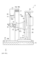
- FIG. 1 is a front view of the three-dimensional inkjet printer according to the present embodiment
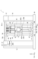
- FIG. 2 is a cross-sectional view taken along the line II-II in FIG. 1
- FIG. 3 is a partial perspective view of the three-dimensional inkjet printer shown in FIG. is there.
- the left-right direction in FIG. 1 front-rear direction in FIG. 2 is the Y-axis direction
- the front-rear direction in FIG. 1 left-right direction in FIG. 2
- the up-down direction in FIG. (Vertical direction of 2) is defined as the Z-axis direction.
- the three-dimensional inkjet printer 1 prints on the surface of a hemispherical medium M, and includes an inkjet head 20 that ejects ink and a three-dimensional medium M.
- the image is printed on the surface of the medium M by causing the ink to be ejected from the inkjet head 20 by relatively moving the medium holding unit 40 that holds the medium.
- the three-dimensional ink jet printer 1 has a pair of left and right support legs 11 and 12 erected on a base 10 serving as a base along the Y-axis direction.
- a maintenance station 15 for cleaning the inkjet head 20 is fixed.
- a support girder 17 extending along the Y-axis direction is stretched.
- a pair of Y-axis guide rails 18 a and 18 b extending in the extending direction of the support beam 17 are arranged on the upper surface of the support beam 17 in parallel in the X-axis direction.
- a head carriage 21 on which the inkjet head 20 is mounted is attached to the pair of Y-axis guide rails 18a and 18b so as to be movable in the Y-axis direction.
- the head carriage 21 is connected to a Y-axis drive unit 22 attached to the support beam 17.
- the Y-axis drive unit 22 includes, for example, a Y-axis drive motor that rotates about an axis in the Y-axis direction, a ball screw connected to the Y-axis drive motor, and a ball bearing that serves as a bearing for the ball screw.
- This is realized by a known mechanism composed of
- the head carriage 21 rotates in the Y-axis drive table by the drive control of the Y-axis drive unit 22 by the control device 14, and is guided by the pair of Y-axis guide rails 18a and 18b to move in the Y-axis direction. .
- the inkjet head 20 prints a color image on the surface of the medium M held by the medium holding unit 40 by discharging ink such as yellow, magenta, cyan, and black. For this reason, the inkjet head 20 is provided for each color type of ink to be ejected. Each inkjet head 20 is disposed at the lower end of the head carriage 21 so as to face the medium M held by the medium holding unit 40. Further, the lower surface of the inkjet head 20 is a nozzle surface, which is a nozzle surface on which a plurality of nozzles 20a for discharging ink such as yellow, magenta, cyan, and black are arranged.
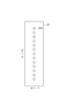
- FIG. 4 shows the nozzle surface of the inkjet head.
- the inkjet head 20 is provided with a plurality of nozzles 20a arranged in the sub-scanning direction (X-axis direction) perpendicular to the main scanning direction (Y-axis direction). Note that all of these nozzles 20a can eject ink droplets. However, since the ink droplets ejected from the nozzle 20a disposed at the end of the inkjet head 20 are likely to generate mist and have a poor landing position accuracy, the nozzle 20a disposed at the end of the inkjet head 20 is not suitable. Only the excluded predetermined nozzles 20a are effective nozzles used for printing.
- a pair of X-axis guide rails 19a and 19b extending in the X-axis direction are arranged in parallel in the Y-axis direction between the pair of support legs 11 and 12.
- An X table 31 for mounting the media holding unit 40 is attached to the pair of X axis guide rails 19a and 19b so as to be movable in the X axis direction.
- the X table 31 is a table for moving the media holding unit 40 relative to the inkjet head 20 in the X-axis direction, and is connected to the X-axis drive unit 23 attached to the base 10.
- the X-axis drive unit 23 includes, for example, an X-axis drive motor that rotates around an axis in the X-axis direction, a ball screw connected to the X-axis drive motor, and a ball bearing that serves as a bearing for the ball screw.
- the X table 31 is driven by the X-axis drive motor 23 by the control device 14 to be driven to rotate, and is guided by the pair of X-axis guide rails 19a and 19b to move in the X-axis direction. .
- the X table 31 is provided with a Z-axis support portion 32 extending in the Z-axis direction.
- the Z-axis support part 32 is a support member that supports the media holding part 40 so as to be movable up and down in the Z-axis direction. For this reason, a pair of side wall portions 33a and 33b erected in the Z-axis direction and a top plate portion 34 that connects the upper surfaces of the pair of side wall portions 33a and 33b are attached to the Z-axis support portion 32. And between the pair of side wall portions 33a, 33b, an elevating mechanism 35 for lifting the media holding portion 40 in the Z-axis direction is attached along the side wall portions 33a, 33b.
- the elevating mechanism 35 is disposed between the pair of side wall portions 33a and 33b and is fixed to the X table 31, and is connected to the output shaft of the Z axis drive motor 37 so as to extend in the Z axis direction.
- the ball screw 38 is erected, and the ball bearing 39 is a bearing of the ball screw 38 and is connected to the media holding unit 40.
- the ball screw 38 is rotated by the drive control of the Z-axis drive motor 37 by the control device 14, and the media holding unit 40 is moved in the Z-axis direction by raising and lowering the ball bearing 39 in the Z-axis direction by the rotation of the ball screw 38. Go up and down.
- the media holding unit 40 holds the media M so that it can rotate and revolve.
- the media holding part 40 includes a Z table 41 attached to the ball bearing 39 of the lifting mechanism 35, a pair of arm parts 42a and 42b protruding from the Z table 41 in the X-axis direction, and a pair of arm parts 42a, An A-axis rotating part 43 that is rotatably attached to 42 b and a chuck 44 that is rotatably attached to the A-axis rotating part 43 and holds the medium M are configured.
- the pair of arm portions 42a and 42b are disposed to face each other in the Y-axis direction, and hold the A-axis rotating portion 43 so as to be swingable. That is, a rotating shaft extending in the Y-axis direction is attached to the tip of a pair of opposed arm portions 42a and 42b, and an A-axis rotating portion 43 is attached to this rotating shaft.
- the output shaft of the A-axis drive motor 45 fixed to one arm portion 42a is connected to the rotating shaft.
- the A-axis drive motor 45 is rotationally driven in the A-axis direction, which is the rotation direction around the rotation axis attached to the pair of arm portions 42a and 42b.
- the A-axis drive motor 45 when the A-axis drive motor 45 is driven to rotate, the A-axis rotation unit 43 swings in the A-axis direction, and the medium M held by the chuck 44 is centered on the rotation axis of the A-axis rotation unit 43. Due to the revolution, the surface of the medium M facing the inkjet head 20 can be moved in the X-axis direction, which is the sub-scanning direction.
- the A-axis rotating unit 43 holds the chuck 44 so that it can rotate. That is, the A-axis rotating unit 43 is for the B-axis that is driven to rotate in the B-axis direction, which is the rotation direction around the rotation axis, with the axis in the direction perpendicular to the rotation axis of the A-axis rotating unit 43 as the rotation axis A drive motor 46 is attached. A chuck 44 that holds the medium M is attached to the output shaft of the B-axis drive motor 46. For this reason, when the B-axis drive motor 46 is driven to rotate, the chuck 44 rotates in the B-axis direction, and the medium M held by the chuck 44 also rotates about the rotation axis of the chuck 44. 20 can be moved in the Y-axis direction which is the main scanning direction.
- the control device 14 is a control device that performs drive control for relatively moving the media holding unit 40 and the inkjet head 20, ink ejection control of the inkjet head 20, and the like. That is, the control device 14 controls the X-axis drive unit 23, the Y-axis drive unit 22, the Z-axis drive motor 37, the A-axis drive motor 45, and the B-axis drive motor 46 based on a predetermined printing schedule. A control signal to be controlled is generated, and the generated control signal is transmitted to the X-axis drive unit 23, the Y-axis drive unit 22, the Z-axis drive motor 37, the A-axis drive motor 45, and the B-axis drive motor 46. Thus, drive control of the inkjet head 20 is performed.
- the X-axis drive unit 23, the Y-axis drive unit 22, the Z-axis drive motor 37, the A-axis drive motor 45, and the B-axis drive motor 46 rotate according to the level of the input voltage value. Since a motor that increases or decreases the number is used as a drive source, the control signal is represented by a voltage value for driving each motor.
- noise that is a disturbance is superimposed on the control signal. That is, the control device 14 generates a control signal based on the print schedule, and noise is superimposed on the control signal for controlling the A-axis drive motor 45 and the B-axis drive motor 46 among the control signals.
- This noise is represented by a waveform that vibrates across positive and negative, and is represented by a predetermined waveform, a waveform derived based on a random number value, a waveform derived based on a predetermined mathematical expression, or the like. .
- the amplitude of the noise is set so as to fluctuate within a range in which the amount of deviation of the ink droplets that land on the surface of the medium M is less than half a dot.
- the gap between the inkjet head 20 and the medium M is 3.0 mm
- the dot diameter is 100.0 ⁇ m
- the inclination angle in the A-axis direction of the medium M is 3.9105 °
- the amplitude of the noise is set so that the inclination angle of the angle fluctuates in the range of 3.90375 ° to 3.91725 °.
- the amount of deviation of the ink droplets that land on the surface of the medium M fluctuates within a range that is less than half a dot.
- Ink droplets ejected from the inkjet head 20 land on the surface of the medium M in a non-uniform manner within a range of half a dot or less.
- the coordinate data of the ink droplets that land on the surface of the medium M can be shifted. .
- the noise amplitude can be obtained by superimposing noises of various amplitudes and frequencies on the control signal in advance and measuring the landing position of the ink droplet, thereby obtaining an optimum value.
- the random value can be generated by a random number generator (not shown) using a predetermined mathematical formula.
- a printing schedule by the three-dimensional inkjet printer 1 is calculated according to the shape of the medium M attached to the chuck 44 of the medium holding unit 40.
- the printing schedule is a schedule for moving the X-axis, Y-axis, Z-axis, A-axis, and B-axis in the three-dimensional inkjet printer 1 and maintains the gap between the medium M and the inkjet head 20 substantially constant.
- the printing position on the surface of the medium M is substantially parallel to the nozzle surface of the inkjet head 20 (the normal line of the printing position on the surface of the medium M is the ejection direction of the ink droplets ejected from the nozzle 20a of the inkjet head 20).
- a schedule for moving the inkjet head 20 and the medium M is a schedule for moving the inkjet head 20 and the medium M.
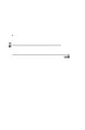
- FIG. 5 is a waveform diagram showing an example of a control signal before noise is superimposed. As shown in FIG. 5, the control signal is represented by a voltage value with respect to the time axis.
- the drive amount of the X-axis drive unit 23, the Y-axis drive unit 22, the Z-axis drive motor 37, the A-axis drive motor 45, and the B-axis drive motor 46 (the number of rotations of the motor) ) Is adjusted. Note that all of the control signals may be generated before printing, or may be generated at any time during printing.
- FIG. 6 is a waveform diagram illustrating an example of noise superimposed on a control signal
- FIG. 7 is a waveform diagram illustrating an example of a control signal on which noise is superimposed.
- the noise is represented by a voltage value with respect to the time axis, like the control signal.
- the voltage value of the control signal becomes a waveform that fluctuates (vibrates) within a predetermined width.
- the X-axis drive unit 23, the Y-axis drive unit 22, the Z-axis drive motor 37, the A-axis drive motor 45, and the B-axis drive motor 46 are generated based on these control signals.
- the X-axis drive unit 23, the Y-axis drive unit 22, the Z-axis drive motor 37, the A-axis drive motor 45, and the B-axis drive motor 46 are controlled to drive the X-axis drive unit 23, the Y-axis drive unit 22, the Z-axis drive motor 37, the A-axis drive motor 45, and the B-axis drive motor 46 according to the print schedule. More specifically, the X-axis drive unit 23 and the Y-axis drive unit 22 are driven to place the medium M immediately below the inkjet head 20 in the Z-axis direction.
- the B-axis drive motor 46 is driven to rotate the medium M in the B-axis direction, and the A-axis drive motor 45 and the Z-axis drive motor 37 are driven to set the print position on the surface of the medium M to the inkjet head 20.
- the nozzle face is arranged opposite to the nozzle face.
- the printing position on the surface of the medium M is substantially parallel to the nozzle surface of the inkjet head 20 while keeping the gap between the medium M and the inkjet head 20 substantially constant (the normal line of the printing position on the surface of the medium M).
- the inkjet head 20 and the medium M are moved so as to substantially coincide with the ejection direction of the ink droplets ejected from the nozzles 20a of the inkjet head 20.
- the B-axis drive motor 46 by driving the B-axis drive motor 46 to rotate the medium M in the B-axis direction, the surface of the medium M facing the inkjet head 20 moves in the Y-axis direction, which is the main scanning direction. Further, the A-axis drive motor 45 is driven to revolve the medium M in the A-axis direction, and the Z-axis drive motor 37 is driven to move the medium M in the Z-axis direction so as to face the inkjet head 20. The surface of the medium M to be moved moves in the X-axis direction that is the sub-scanning direction.
- FIG. 8 is a diagram showing the relationship between the medium and the inkjet head when ejecting ink droplets while generating vibration.
- an effective nozzle to be used for printing is selected from the plurality of nozzles 20a provided in the inkjet head 20. Then, ink droplets are ejected from the selected effective nozzle during a period in which the medium M rotates once or a plurality of times while finely fluctuating in the A axis direction and the B axis direction, and the medium M has a predetermined pass width. Print the image. As shown in FIG. 9, when the rotation angle position of the medium M at which printing is started is 0 °, the boundary between the 0 ° position and the 360 ° position is a joint between the print images.
- the ink droplets ejected from the inkjet head 20 are in the X axis direction (sub-scanning direction) on the surface of the medium M. And land at positions shifted non-uniformly in the Y-axis direction (main scanning direction).
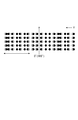
- FIG. 10 is a diagram showing the landing positions of ink droplets when noise is superimposed on a control signal for controlling the A-axis drive motor.
- FIG. 10 shows a case where one pass is constituted by five dots with five consecutive nozzles 20a as effective nozzles.
- FIG. 10 shows a case where one pass is constituted by five dots with five consecutive nozzles 20a as effective nozzles.
- ink droplets are formed on the surface of the medium M at every discharge timing of the ink droplets discharged from the inkjet head 20.
- the dot positions on the surface of the medium M are shifted unevenly as a whole in the direction of adjacent passes. For this reason, blur occurs at the boundary between adjacent passes, and the print density between passes is averaged.
- FIG. 11 is a diagram showing the landing positions of ink droplets when noise is superimposed on a control signal for controlling the B-axis drive motor. Note that FIG. 11 shows a case where one pass is constituted by five dots with five consecutive nozzles 20a as effective nozzles. As shown in FIG. 11, when the medium M rotates while fluctuating in the B-axis direction, ink droplets are formed on the surface of the medium M at the discharge timing of the ink droplets discharged from the inkjet head 20 in the Y-axis direction.
- the dot position on the surface of the medium M shifts as a whole toward the joint ⁇ direction of the image in the pass. For this reason, blur occurs in the joint ⁇ of the image in the pass, and the density of the printed image across the joint ⁇ is averaged.
- the A-axis drive motor 45 and the Z-axis drive motor 37 are driven to print the next pass on the nozzle surface of the inkjet head 20. Are placed opposite each other. Thereafter, the image for one pass is printed, and the above processing operation is repeated until all the images are printed.
- ink droplets are ejected from the inkjet head 20 while the medium M is rotated by the drive control of the B-axis drive motor 46 by the control device 14.
- An image can be printed on the surface of the medium M, and the path position for printing on the medium M can be changed by revolving the medium M by the drive control of the A-axis drive motor 45 by the control device 14.
- the control device 14 gives a disturbance to the control signals for controlling the B-axis drive motor 46 and the A-axis drive motor 45, the medium M is in the main scanning direction (B-axis direction) with respect to the inkjet head 20.
- the landing positions of the ink droplets ejected from the inkjet head 20 are shifted unevenly as a whole.
- the deviation of the dot positions can be made visually inconspicuous, so that unevenness in print density can be reduced.
- the landing position of the ink droplet can be intentionally shifted easily and reliably by changing the voltage value of the control signal.
- the medium M slightly fluctuates in the sub-scanning direction with respect to the ink-jet head 20 when the medium M is rotated.
- the landing positions of the ink droplets ejected from the head are displaced unevenly as a whole in the sub-scanning direction (X-axis direction). For this reason, when an image is printed on the medium M in a plurality of passes, the dot interval of the ink droplets between adjacent passes can be made non-uniform, so that a linear shape generated at the joint of the printed images between passes. The joint unevenness can be reduced.
- the medium M slightly fluctuates in the main scanning direction with respect to the ink-jet head 20 when the medium M is rotated.
- the landing positions of the ink droplets ejected from the head are displaced unevenly as a whole in the main scanning direction (Y-axis direction). For this reason, when printing an image on the medium M in the same pass, the dot intervals of the ink droplets in the joint ⁇ of the print image in the same pass can be made non-uniform, so the joint ⁇ of the print image in the same pass It is possible to reduce the unevenness of the linear seam that occurs in the case.
- the adjacent ink droplets may be displaced toward each other and land on the media surface. Since these ink droplet dots can be prevented from overlapping, image quality deterioration can be suppressed.
- the landing positions of the ink droplets can be irregularly dispersed, so that the deviation of the dot positions can be made visually inconspicuous.
- the landing positions of the ink droplets can be more irregularly distributed, so that the deviation of the dot positions is visually inconspicuous. be able to.
- control signal has been described as being expressed by a voltage value with respect to the time axis, but any signal may be used as long as it is a signal for adjusting the control amount of the driving means that drives each axis. Also good.
- the present invention can be used as a three-dimensional ink jet printer that discharges ink droplets from an ink jet head and performs printing on the surface of a three-dimensional medium.
- SYMBOLS 1 Three-dimensional inkjet printer, 10 ... Base, 11, 12 ... Supporting leg, 13 ... Control panel, 14 ... Control device, 15 ... Maintenance station, 17 ... Supporting girder, 18a, 18b ... Y-axis guide rail, 19a, 19b ... X-axis guide rail, 20 ... ink jet head, 20a ... nozzle, 21 ... head carriage, 22 ... Y-axis drive, 23 ... X-axis drive, 31 ... X table, 32 ... Z-axis support, 33a, 33b ... Side wall part, 34 ... Top plate part, 35 ... Elevating mechanism, 37 ... Z axis drive motor, 38 ...
- Ball screw 39 ... Ball bearing, 40 ... Media holding part, 41 ... Z table, 42a, 42b ... Arm , 43 ... A-axis rotating part, 44 ... Chuck, 45 ... A-axis drive motor, 46 ... B-axis drive motor, M ... Media.
Abstract
Description
The present invention can be used as a three-dimensional ink jet printer that discharges ink droplets from an ink jet head and performs printing on the surface of a three-dimensional medium.
Claims (7)
- 三次元形状のメディアを保持するメディア保持部とインクジェットヘッドとを相対的に移動させながら前記メディアの表面に前記インクジェットヘッドからインク液滴を吐出して前記メディア表面に印刷を行う三次元インクジェットプリンタであって、
前記メディアを自転させて、前記インクジェットヘッドに対向する前記メディアの表面を主走査方向に移動させるB軸用駆動部と、
前記メディアを公転させて、前記インクジェットヘッドに対向する前記メディアの表面を主走査方向に直交する副走査方向に移動させるA軸用駆動部と、
前記B軸用駆動部及び前記A軸用駆動部の駆動制御を行う駆動制御部と、
を有し、
前記駆動制御部は、前記B軸用駆動部及び前記A軸用駆動部の少なくとも一方を制御するための制御信号に外乱を与える、三次元インクジェットプリンタ。 A three-dimensional ink jet printer that prints on a surface of a medium by ejecting ink droplets from the ink jet head onto the surface of the medium while relatively moving a medium holding unit that holds the medium of a three-dimensional shape and the ink jet head. There,
A B-axis drive unit that rotates the medium and moves the surface of the medium facing the inkjet head in the main scanning direction;
An A-axis drive unit that revolves the medium and moves the surface of the medium facing the inkjet head in a sub-scanning direction orthogonal to the main scanning direction;
A drive control unit that performs drive control of the B-axis drive unit and the A-axis drive unit;
Have
The three-dimensional ink jet printer, wherein the drive control unit gives a disturbance to a control signal for controlling at least one of the B-axis drive unit and the A-axis drive unit. - 前記制御信号は電圧値で表されており、
前記駆動制御部は、前記制御信号の電圧値を変動させることで、前記制御信号に外乱を与える、請求項1に記載の三次元インクジェットプリンタ。 The control signal is represented by a voltage value,
The three-dimensional ink jet printer according to claim 1, wherein the drive control unit gives a disturbance to the control signal by changing a voltage value of the control signal. - 前記駆動制御部は、前記A軸用駆動部を制御するための制御信号に外乱を与える、請求項1又は2に記載の三次元インクジェットプリンタ。 The three-dimensional ink jet printer according to claim 1 or 2, wherein the drive control unit gives a disturbance to a control signal for controlling the A-axis drive unit.
- 前記駆動制御部は、前記B軸用駆動部を制御するための制御信号に外乱を与える、請求項1又は2に記載の三次元インクジェットプリンタ。 The three-dimensional ink jet printer according to claim 1 or 2, wherein the drive control unit gives a disturbance to a control signal for controlling the B-axis drive unit.
- 前記駆動制御部は、前記メディアに着弾するインク液滴のズレ量が半ドット以下となる範囲で前記制御信号に外乱を与える、請求項1~4の何れか1項に記載の三次元インクジェットプリンタ。 The three-dimensional ink jet printer according to any one of claims 1 to 4, wherein the drive control unit applies disturbance to the control signal in a range where a deviation amount of ink droplets that land on the medium is equal to or less than a half dot. .
- 前記駆動制御部は、前記制御信号に与える外乱を変動させる、請求項1~5の何れか1項に記載の三次元インクジェットプリンタ。 The three-dimensional ink jet printer according to any one of claims 1 to 5, wherein the drive control unit varies a disturbance given to the control signal.
- 前記駆動制御部は、前記制御信号に与える外乱を乱数値に基づいて変動させる、請求項1~5の何れか1項に記載の三次元インクジェットプリンタ。 The three-dimensional inkjet printer according to any one of claims 1 to 5, wherein the drive control unit varies a disturbance given to the control signal based on a random value.
Priority Applications (6)
| Application Number | Priority Date | Filing Date | Title |
|---|---|---|---|
| EP09848758.0A EP2474419A4 (en) | 2009-08-31 | 2009-08-31 | Three-dimensional inkjet printer |
| KR1020127004895A KR101271652B1 (en) | 2009-08-31 | 2009-08-31 | Three-Dimensional Inkjet Printer |
| US13/392,089 US20120188299A1 (en) | 2009-08-31 | 2009-08-31 | Three-dimensional inkjet printer |
| CN2009801611086A CN102481781A (en) | 2009-08-31 | 2009-08-31 | Three-dimensional inkjet printer |
| JP2011528588A JPWO2011024313A1 (en) | 2009-08-31 | 2009-08-31 | 3D inkjet printer |
| PCT/JP2009/065208 WO2011024313A1 (en) | 2009-08-31 | 2009-08-31 | Three-dimensional inkjet printer |
Applications Claiming Priority (1)
| Application Number | Priority Date | Filing Date | Title |
|---|---|---|---|
| PCT/JP2009/065208 WO2011024313A1 (en) | 2009-08-31 | 2009-08-31 | Three-dimensional inkjet printer |
Publications (1)
| Publication Number | Publication Date |
|---|---|
| WO2011024313A1 true WO2011024313A1 (en) | 2011-03-03 |
Family
ID=43627437
Family Applications (1)
| Application Number | Title | Priority Date | Filing Date |
|---|---|---|---|
| PCT/JP2009/065208 WO2011024313A1 (en) | 2009-08-31 | 2009-08-31 | Three-dimensional inkjet printer |
Country Status (6)
| Country | Link |
|---|---|
| US (1) | US20120188299A1 (en) |
| EP (1) | EP2474419A4 (en) |
| JP (1) | JPWO2011024313A1 (en) |
| KR (1) | KR101271652B1 (en) |
| CN (1) | CN102481781A (en) |
| WO (1) | WO2011024313A1 (en) |
Cited By (1)
| Publication number | Priority date | Publication date | Assignee | Title |
|---|---|---|---|---|
| JP2015227034A (en) * | 2014-06-02 | 2015-12-17 | 株式会社リコー | Liquid droplet discharging recording apparatus, liquid droplet discharging recording method, and program for controlling liquid droplet discharging recording apparatus |
Families Citing this family (8)
| Publication number | Priority date | Publication date | Assignee | Title |
|---|---|---|---|---|
| DE102013214980A1 (en) * | 2013-07-31 | 2015-02-05 | Krones Ag | Printing machine with printhead control |
| KR101564554B1 (en) * | 2014-06-03 | 2015-10-30 | (주)하이비젼시스템 | Level aligning device for bed of 3d printer |
| CN104210104B (en) * | 2014-09-23 | 2016-08-24 | 哈尔滨工程大学 | A kind of pose adjustable 3D print apparatus |
| WO2016140707A1 (en) | 2015-03-04 | 2016-09-09 | Stolle Machinery Company, Llc | Digital printing machine and method |
| US9983569B2 (en) * | 2016-08-22 | 2018-05-29 | Scandy, LLC | System and method for representing a field of capture as physical media |
| US10913995B2 (en) | 2017-07-14 | 2021-02-09 | Stolle Machinery Company, Llc | Pretreatment assembly and method for treating work pieces |
| US10259249B2 (en) | 2017-07-14 | 2019-04-16 | Stolle Machinery Company, Llc | Post-treatment assembly and method for treating work pieces |
| US11526076B2 (en) | 2020-11-18 | 2022-12-13 | Canon Kabushiki Kaisha | Nanofabrication system with dispensing system for rotational dispensing |
Citations (2)
| Publication number | Priority date | Publication date | Assignee | Title |
|---|---|---|---|---|
| JP2006187877A (en) * | 2004-12-28 | 2006-07-20 | Brother Ind Ltd | Inkjet recording apparatus |
| JP2007008110A (en) * | 2005-07-04 | 2007-01-18 | Mimaki Engineering Co Ltd | Inkjet printer for sphere media print and printing method using the same |
Family Cites Families (6)
| Publication number | Priority date | Publication date | Assignee | Title |
|---|---|---|---|---|
| US6425699B1 (en) * | 1999-09-29 | 2002-07-30 | Hewlett-Packard Company | Use of very small advances of printing medium for improved image quality in incremental printing |
| US6460958B2 (en) * | 2000-02-29 | 2002-10-08 | Minolta Co., Ltd. | Three-dimensional object printing apparatus and method |
| ITTO20010707A1 (en) * | 2001-07-19 | 2003-01-20 | Olivetti I Jet Spa | PRINTING DEVICE WITH PARALLEL INK JET HEAD. |
| US20030085934A1 (en) * | 2001-11-07 | 2003-05-08 | Tucker Robert Carey | Ink-jet printing system for printing colored images on contact lenses |
| US7744184B2 (en) * | 2007-01-23 | 2010-06-29 | Marvell World Trade Ltd. | Mechanical dithering of printing mechanisms |
| JP2009184118A (en) | 2008-02-01 | 2009-08-20 | Mimaki Engineering Co Ltd | Three-dimensional printer |
-
2009
- 2009-08-31 WO PCT/JP2009/065208 patent/WO2011024313A1/en active Application Filing
- 2009-08-31 EP EP09848758.0A patent/EP2474419A4/en not_active Withdrawn
- 2009-08-31 JP JP2011528588A patent/JPWO2011024313A1/en active Pending
- 2009-08-31 CN CN2009801611086A patent/CN102481781A/en active Pending
- 2009-08-31 KR KR1020127004895A patent/KR101271652B1/en active IP Right Grant
- 2009-08-31 US US13/392,089 patent/US20120188299A1/en not_active Abandoned
Patent Citations (2)
| Publication number | Priority date | Publication date | Assignee | Title |
|---|---|---|---|---|
| JP2006187877A (en) * | 2004-12-28 | 2006-07-20 | Brother Ind Ltd | Inkjet recording apparatus |
| JP2007008110A (en) * | 2005-07-04 | 2007-01-18 | Mimaki Engineering Co Ltd | Inkjet printer for sphere media print and printing method using the same |
Non-Patent Citations (1)
| Title |
|---|
| See also references of EP2474419A4 * |
Cited By (1)
| Publication number | Priority date | Publication date | Assignee | Title |
|---|---|---|---|---|
| JP2015227034A (en) * | 2014-06-02 | 2015-12-17 | 株式会社リコー | Liquid droplet discharging recording apparatus, liquid droplet discharging recording method, and program for controlling liquid droplet discharging recording apparatus |
Also Published As
| Publication number | Publication date |
|---|---|
| CN102481781A (en) | 2012-05-30 |
| KR101271652B1 (en) | 2013-06-11 |
| US20120188299A1 (en) | 2012-07-26 |
| EP2474419A4 (en) | 2013-09-04 |
| JPWO2011024313A1 (en) | 2013-01-24 |
| EP2474419A1 (en) | 2012-07-11 |
| KR20120046288A (en) | 2012-05-09 |
Similar Documents
| Publication | Publication Date | Title |
|---|---|---|
| WO2011024312A1 (en) | Three-dimensional inkjet printer | |
| WO2011024313A1 (en) | Three-dimensional inkjet printer | |
| JP5407092B2 (en) | 3D inkjet printer | |
| JP4859236B2 (en) | Recording apparatus and recording method | |
| JP3313819B2 (en) | Recording device and method | |
| JPWO2010067445A6 (en) | 3D inkjet printer | |
| US20080218542A1 (en) | Printer and printing method | |
| KR20080041095A (en) | Three-dimensional printer | |
| JP2008183903A (en) | Printer having adjustable attaching position of print head to carriage | |
| JP2004136555A (en) | Printer having adjustable securing position of print head to carriage | |
| JP4513875B2 (en) | Printing device capable of adjusting the mounting position of the print head on the carriage | |
| JP2013000997A (en) | Image recording device, and image recording method | |
| JP2016179591A (en) | Printing device and printing method | |
| JP2009184118A (en) | Three-dimensional printer | |
| JP5322605B2 (en) | Inkjet printer | |
| JP2016022665A (en) | Liquid discharge device and liquid discharge method | |
| EP1412194B1 (en) | Printing device with parallel type ink jet printhead | |
| JP5316112B2 (en) | Image forming apparatus | |
| US7083246B2 (en) | Electronic tilt adjustment in fluid-jet fluid ejecting heads | |
| JPS58188661A (en) | Recording apparatus | |
| JP2009119764A (en) | Liquid injection device | |
| JP2010125744A (en) | Inkjet printer | |
| JP2017222036A (en) | Ink jet printer | |
| JP2001180045A (en) | Image recording device | |
| JPH0664175A (en) | Printer device |
Legal Events
| Date | Code | Title | Description |
|---|---|---|---|
| WWE | Wipo information: entry into national phase |
Ref document number: 200980161108.6 Country of ref document: CN |
|
| 121 | Ep: the epo has been informed by wipo that ep was designated in this application |
Ref document number: 09848758 Country of ref document: EP Kind code of ref document: A1 |
|
| WWE | Wipo information: entry into national phase |
Ref document number: 2009848758 Country of ref document: EP |
|
| ENP | Entry into the national phase |
Ref document number: 20127004895 Country of ref document: KR Kind code of ref document: A |
|
| NENP | Non-entry into the national phase |
Ref country code: DE |
|
| WWE | Wipo information: entry into national phase |
Ref document number: 2011528588 Country of ref document: JP |
|
| WWE | Wipo information: entry into national phase |
Ref document number: 13392089 Country of ref document: US |