WO2011016247A1 - Procédé de codage, procédé de décodage, dispositif de codage et dispositif de décodage - Google Patents
Procédé de codage, procédé de décodage, dispositif de codage et dispositif de décodage Download PDFInfo
- Publication number
- WO2011016247A1 WO2011016247A1 PCT/JP2010/004950 JP2010004950W WO2011016247A1 WO 2011016247 A1 WO2011016247 A1 WO 2011016247A1 JP 2010004950 W JP2010004950 W JP 2010004950W WO 2011016247 A1 WO2011016247 A1 WO 2011016247A1
- Authority
- WO
- WIPO (PCT)
- Prior art keywords
- conversion
- signal
- output signal
- decoded
- unit
- Prior art date
Links
Images


Classifications
-
- H—ELECTRICITY
- H04—ELECTRIC COMMUNICATION TECHNIQUE
- H04N—PICTORIAL COMMUNICATION, e.g. TELEVISION
- H04N19/00—Methods or arrangements for coding, decoding, compressing or decompressing digital video signals
- H04N19/42—Methods or arrangements for coding, decoding, compressing or decompressing digital video signals characterised by implementation details or hardware specially adapted for video compression or decompression, e.g. dedicated software implementation
-
- H—ELECTRICITY
- H04—ELECTRIC COMMUNICATION TECHNIQUE
- H04N—PICTORIAL COMMUNICATION, e.g. TELEVISION
- H04N19/00—Methods or arrangements for coding, decoding, compressing or decompressing digital video signals
- H04N19/10—Methods or arrangements for coding, decoding, compressing or decompressing digital video signals using adaptive coding
- H04N19/102—Methods or arrangements for coding, decoding, compressing or decompressing digital video signals using adaptive coding characterised by the element, parameter or selection affected or controlled by the adaptive coding
- H04N19/132—Sampling, masking or truncation of coding units, e.g. adaptive resampling, frame skipping, frame interpolation or high-frequency transform coefficient masking
-
- H—ELECTRICITY
- H04—ELECTRIC COMMUNICATION TECHNIQUE
- H04N—PICTORIAL COMMUNICATION, e.g. TELEVISION
- H04N19/00—Methods or arrangements for coding, decoding, compressing or decompressing digital video signals
- H04N19/10—Methods or arrangements for coding, decoding, compressing or decompressing digital video signals using adaptive coding
- H04N19/102—Methods or arrangements for coding, decoding, compressing or decompressing digital video signals using adaptive coding characterised by the element, parameter or selection affected or controlled by the adaptive coding
- H04N19/12—Selection from among a plurality of transforms or standards, e.g. selection between discrete cosine transform [DCT] and sub-band transform or selection between H.263 and H.264
- H04N19/122—Selection of transform size, e.g. 8x8 or 2x4x8 DCT; Selection of sub-band transforms of varying structure or type
-
- H—ELECTRICITY
- H04—ELECTRIC COMMUNICATION TECHNIQUE
- H04N—PICTORIAL COMMUNICATION, e.g. TELEVISION
- H04N19/00—Methods or arrangements for coding, decoding, compressing or decompressing digital video signals
- H04N19/10—Methods or arrangements for coding, decoding, compressing or decompressing digital video signals using adaptive coding
- H04N19/102—Methods or arrangements for coding, decoding, compressing or decompressing digital video signals using adaptive coding characterised by the element, parameter or selection affected or controlled by the adaptive coding
- H04N19/124—Quantisation
-
- H—ELECTRICITY
- H04—ELECTRIC COMMUNICATION TECHNIQUE
- H04N—PICTORIAL COMMUNICATION, e.g. TELEVISION
- H04N19/00—Methods or arrangements for coding, decoding, compressing or decompressing digital video signals
- H04N19/10—Methods or arrangements for coding, decoding, compressing or decompressing digital video signals using adaptive coding
- H04N19/102—Methods or arrangements for coding, decoding, compressing or decompressing digital video signals using adaptive coding characterised by the element, parameter or selection affected or controlled by the adaptive coding
- H04N19/129—Scanning of coding units, e.g. zig-zag scan of transform coefficients or flexible macroblock ordering [FMO]
-
- H—ELECTRICITY
- H04—ELECTRIC COMMUNICATION TECHNIQUE
- H04N—PICTORIAL COMMUNICATION, e.g. TELEVISION
- H04N19/00—Methods or arrangements for coding, decoding, compressing or decompressing digital video signals
- H04N19/10—Methods or arrangements for coding, decoding, compressing or decompressing digital video signals using adaptive coding
- H04N19/102—Methods or arrangements for coding, decoding, compressing or decompressing digital video signals using adaptive coding characterised by the element, parameter or selection affected or controlled by the adaptive coding
- H04N19/13—Adaptive entropy coding, e.g. adaptive variable length coding [AVLC] or context adaptive binary arithmetic coding [CABAC]
-
- H—ELECTRICITY
- H04—ELECTRIC COMMUNICATION TECHNIQUE
- H04N—PICTORIAL COMMUNICATION, e.g. TELEVISION
- H04N19/00—Methods or arrangements for coding, decoding, compressing or decompressing digital video signals
- H04N19/10—Methods or arrangements for coding, decoding, compressing or decompressing digital video signals using adaptive coding
- H04N19/169—Methods or arrangements for coding, decoding, compressing or decompressing digital video signals using adaptive coding characterised by the coding unit, i.e. the structural portion or semantic portion of the video signal being the object or the subject of the adaptive coding
- H04N19/18—Methods or arrangements for coding, decoding, compressing or decompressing digital video signals using adaptive coding characterised by the coding unit, i.e. the structural portion or semantic portion of the video signal being the object or the subject of the adaptive coding the unit being a set of transform coefficients
-
- H—ELECTRICITY
- H04—ELECTRIC COMMUNICATION TECHNIQUE
- H04N—PICTORIAL COMMUNICATION, e.g. TELEVISION
- H04N19/00—Methods or arrangements for coding, decoding, compressing or decompressing digital video signals
- H04N19/60—Methods or arrangements for coding, decoding, compressing or decompressing digital video signals using transform coding
-
- H—ELECTRICITY
- H04—ELECTRIC COMMUNICATION TECHNIQUE
- H04N—PICTORIAL COMMUNICATION, e.g. TELEVISION
- H04N19/00—Methods or arrangements for coding, decoding, compressing or decompressing digital video signals
- H04N19/90—Methods or arrangements for coding, decoding, compressing or decompressing digital video signals using coding techniques not provided for in groups H04N19/10-H04N19/85, e.g. fractals
- H04N19/91—Entropy coding, e.g. variable length coding [VLC] or arithmetic coding
Definitions
- the present invention relates to an encoding method for encoding audio, still images, and moving images, and more particularly to an encoding method including a conversion process for converting an input signal from a space-time domain to a frequency domain.
- H.264 ITU-T As an example of the video coding standard, H.264 ITU-T standard called 26x and ISO / IEC standard called MPEG-x.
- MPEG-x The latest video coding standard is H.264. It is a standard called H.264 / MPEG-4 AVC.
- FIG. 1 is a block diagram showing a configuration of a conventional encoding device 1600.
- the encoding apparatus 1600 includes a conversion unit 1610, a quantization unit 1620, and an entropy encoding unit 1630, and encodes audio data and moving image data at a low bit rate.
- the conversion unit 1610 generates a converted output signal with reduced correlation by converting an input signal, which is various data, or a converted input signal obtained by performing some processing on the input signal from the space-time domain to the frequency domain.
- the generated conversion output signal is output to the quantization unit.
- the quantization unit 1620 quantizes the conversion output signal output from the conversion unit 1610 to generate a quantization coefficient with a small total data amount.
- the generated quantization coefficient is output to the entropy encoding unit.
- the entropy encoding unit 1630 encodes the quantization coefficient output from the quantization unit 1620 using an entropy encoding algorithm, thereby generating an encoded signal obtained by compressing the remaining data.
- the generated encoded signal is recorded on a recording medium, for example, or transmitted to a decoding device or the like via a network.
- n-point vector that is a conversion target signal (that is, a conversion input signal) is input to the conversion unit 1610 as a conversion input vector x n .
- Conversion unit the conversion input vector x n, predetermined conversion process performed (conversion T), as the conversion output signal, and outputs the converted output (Transform Output) vector y n (see equation 1).
- the transformation T When the transformation T is a linear transformation, as shown in Equation 2, the transformation T can be expressed as a matrix product of a transformation matrix (Transform Matrix) A, which is an n ⁇ n square matrix, and a transformation input vector xn .
- Expression 3 is an expression for calculating the conversion output vector y n for each element y i using the conversion coefficient a ik which is each element of the conversion matrix A, and is derived from Expression 1 and Expression 2.
- Transformation matrix A is to reduce the correlation of the input signal, it is designed so that the energy is concentrated to the element having a smaller n among the elements of the transform output vector y n (so-called low frequency side).
- KLT Kerhunen Loeve Transform
- KLT is a method of deriving an optimal conversion coefficient based on the statistical properties of an input signal, or a conversion method using the derived optimal conversion coefficient.
- KLT is known as a technique that can completely eliminate correlation of input signals and can concentrate energy to a low frequency most efficiently.
- KLT is an ideal conversion process, and can encode an encoding target signal converted by KLT with excellent encoding efficiency.
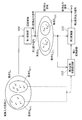
- the KLT shown in the above prior art has a problem that the calculation amount is large and the data amount of the conversion coefficient which is a coefficient of the conversion matrix used for conversion is large. Specifically, it is as follows.
- the number of multiplications when the number of dimensions of the input signal (hereinafter also referred to as the number of input points) is M is M ⁇ Log 2 (M).
- the number of multiplications is M ⁇ M.
- the number of DCT multiplications is 8 when the number of input points is 4, and 24 when the number of input points is 8.
- the number of multiplications of the KLT is, for example, 16 times when the number of input points is 4 (DCT ratio is double), 64 times when the number is 8 points (DCT ratio is 2.6 times), and DCT when the number is 16 points.
- the ratio is 4.0 times.
- the increase in the calculation amount of the KLT becomes more prominent. Therefore, the calculation amount of the KLT is enormous as compared with the DCT.
- the transformation matrix A is derived based on the statistical properties of the set S A including the input signal vector xn . Transformation using the transformation matrix A may perform the energy compaction of the input signal vector x n in set S A, the optimum decorrelation and the low frequency. However, when an input signal vector included in the set S B having statistical characteristics different from the set S A assumed at the time of design is input, the conversion result using the conversion matrix A is not optimal. Conversely, if the optimum is always obtained and a conversion coefficient is generated for every slight change in the statistical properties of the input, the data amount of the conversion coefficient becomes enormous.
- the transformation using a transformation matrix composed of transformation coefficients calculated based on the statistical properties of the input signal, such as KLT has a large amount of calculation and a large amount of data of the transformation coefficients. Therefore, it has been difficult to use KLT in the conventional encoding.
- an object is to provide an encoding device. Furthermore, an object of the present invention is to provide a decoding method and a decoding apparatus that can correctly decode a signal encoded by the encoding method and the encoding apparatus according to the present invention.
- an encoding method includes a conversion step of converting an input signal to generate a converted output signal, and quantizing the converted output signal to quantize the converted output signal.
- a second converted output signal is generated, and the generated second converted output signal and the second partial signal that is a portion other than the first partial signal in the first converted output signal are included.
- Output conversion output signal A second conversion step, wherein, in the second conversion step, as the first partial signal, at least a range to be subjected to the second conversion of the first conversion output signal and the second conversion coefficient
- the first conversion output signal is generated by performing the first conversion of the first step on the input signal, and the second step is performed on the first partial signal that is a part of the first conversion output signal.
- the second conversion is performed. Since the first partial signal to be subjected to the second conversion has a smaller number of dimensions than the first conversion output signal, it is possible to reduce the amount of calculation and the total number of conversion coefficients. Also, the conversion that reduces the correlation can be performed by the two conversions of the first conversion and the second conversion, and the encoding efficiency can be increased. Furthermore, since at least one of the range to be subjected to the second conversion and the second conversion coefficient is adaptively determined, it is possible to perform a suitable conversion that further reduces the correlation according to the input signal.
- the second conversion step as the first partial signal, at least one of the range to be subjected to the second conversion in the first conversion output signal and the second conversion coefficient is subjected to predetermined encoding. You may determine adaptively based on a parameter.
- the encoding parameter indicates one prediction method out of a plurality of predetermined prediction methods, and the encoding method is further applied to an input image to be encoded based on the encoding parameter.
- the second transformation can be performed on a range in which the correlation is further reduced in accordance with the input signal.
- the predetermined direction among a plurality of coefficient values constituting the first conversion output signal.
- a range including the coefficient value may be determined as the second conversion target.
- the second conversion target is determined according to the extrapolation direction. Since a portion where power is concentrated can be assumed depending on the extrapolation direction, the second conversion can be performed on a range where the correlation is further reduced.
- a range including a coefficient value in the horizontal direction among a plurality of coefficient values constituting the first conversion output signal is determined.
- the target may be determined.
- a range including a coefficient value in the vertical direction among a plurality of coefficient values constituting the first conversion output signal is determined.
- the target may be determined.
- the coding parameter is index information for designating one transformation matrix from among a plurality of transformation matrices having different sets of coefficient values, and is designated by the coding parameter in the second transformation step.
- a transformation matrix may be determined as the second transformation coefficient.
- the decoding method includes an entropy decoding step for generating a decoded quantization coefficient by entropy decoding an encoded signal, and a decoding conversion by dequantizing the decoded quantization coefficient.
- An inverse quantization step for generating an output signal, and an inverse transformation step for producing a decoded signal by inversely transforming the decoded transformation output signal, wherein the inverse transformation step uses a second inverse transformation coefficient
- the encoded signal can be correctly decoded with a small amount of calculation and a small conversion coefficient.
- the second inverse transform step as the second decoded transform output signal, at least one of the range to be subjected to the second inverse transform of the decoded transform output signal and the second inverse transform coefficient, You may determine adaptively based on a predetermined encoding parameter.
- the encoded signal is a signal obtained by encoding a prediction error image indicating a prediction error of an input image, and the encoding parameter indicates one prediction method among a plurality of predetermined prediction methods.
- the decoding method further includes a prediction step of generating a prediction pixel of a decoding target block included in the prediction error image based on the encoding parameter, and a pixel of the decoding target block And an addition step of restoring the input image by adding the prediction pixel and the prediction pixel.
- the predetermined direction among the plurality of coefficient values constituting the decoded transform output signal.
- a range including the coefficient value may be determined as a target of the second inverse transformation.
- the second inverse transformation step when the direction is a substantially horizontal direction, a range including a coefficient value in the horizontal direction among a plurality of coefficient values constituting the decoded transformation output signal is converted into the second inverse transformation. It may be determined as a target of.
- a range including a coefficient value in the vertical direction among a plurality of coefficient values constituting the decoded transform output signal is converted into the second inverse transform. It may be determined as a target of.
- the coding parameter is index information for designating one transformation matrix from a plurality of transformation matrices having different sets of coefficient values.
- the coding parameter is designated by the coding parameter. May be determined as the second inverse transform coefficient.
- any of the above decoding methods as in the case of the encoding method, it is possible to suppress an increase in the amount of computation and an increase in the data amount of transform coefficients. Also, the signal encoded by the above encoding method can be correctly decoded.
- the present invention can be realized not only as an encoding method and a decoding method, but also as an encoding device and a decoding device including a processing unit that performs processing steps included in the encoding method and the decoding method. Moreover, you may implement
- a communication network such as the Internet.
- the system LSI is an ultra-multifunctional LSI manufactured by integrating a plurality of components on a single chip, and specifically includes a microprocessor, ROM, RAM (Random Access Memory), and the like.
- Computer system is an ultra-multifunctional LSI manufactured by integrating a plurality of components on a single chip, and specifically includes a microprocessor, ROM, RAM (Random Access Memory), and the like.
- the present invention it is possible to suppress an increase in the calculation amount and an increase in the data amount of the transform coefficient, and to increase the encoding efficiency.
- FIG. 1 is a block diagram showing a configuration of a conventional encoding apparatus.
- FIG. 2 is a diagram showing a comparison of calculation amounts between DCT and KLT.
- FIG. 3 is a block diagram showing an example of the configuration of the coding apparatus according to Embodiment 1 of the present invention.
- FIG. 4 is a flowchart showing an example of the conversion process according to Embodiment 1 of the present invention.
- FIG. 5A is a diagram conceptually illustrating an example of the data flow of the conversion unit according to Embodiment 1 of the present invention.
- FIG. 5B is a diagram conceptually illustrating another example of the data flow of the conversion unit according to Embodiment 1 of the present invention.
- FIG. 6 is a flowchart showing another example of the conversion process according to Embodiment 1 of the present invention.
- FIG. 7 is a diagram conceptually illustrating an example of conversion coefficient derivation in the conversion unit according to Embodiment 1 of the present invention.
- FIG. 8 is a diagram conceptually illustrating an example of matrix calculation according to Embodiment 1 of the present invention.
- FIG. 9 is a block diagram showing an example of the configuration of the coding apparatus according to the modification of Embodiment 1 of the present invention.
- FIG. 10 is a flowchart showing an example of the operation of the encoding apparatus according to the modification of the first embodiment of the present invention.
- FIG. 11A is a block diagram showing an exemplary configuration of a decoding apparatus according to Embodiment 2 of the present invention.
- FIG. 11B is a block diagram showing an exemplary configuration of an inverse transform unit in the decoding apparatus according to Embodiment 2 of the present invention.
- FIG. 12 is a flowchart showing an example of the operation of the decoding apparatus according to Embodiment 2 of the present invention.
- FIG. 13A is a diagram conceptually illustrating an example of the data flow of the inverse transform unit according to Embodiment 2 of the present invention.
- FIG. 13B is a diagram conceptually illustrating another example of the data flow of the inverse transform unit according to Embodiment 2 of the present invention.
- FIG. 14 is a flowchart showing an example of the inverse conversion process according to Embodiment 2 of the present invention.
- FIG. 15 is a block diagram showing an exemplary configuration of a decoding apparatus according to a modification of the second embodiment of the present invention.
- FIG. 16 is a flowchart showing an example of the operation of the decoding apparatus according to the modification of the second embodiment of the present invention.
- FIG. 17 is a block diagram showing an example of the configuration of the coding apparatus according to Embodiment 3 of the present invention.
- FIG. 18 is a flowchart showing an example of the operation of the coding apparatus according to Embodiment 3 of the present invention.
- FIG. 19 is a block diagram showing an example of the configuration of the conversion unit according to Embodiment 3 of the present invention.
- FIG. 20 is a block diagram showing another example of the configuration of the conversion unit according to Embodiment 3 of the present invention.
- FIG. 21 is a diagram conceptually illustrating an example of the derivation of the transform coefficient in the transform unit according to Embodiment 3 of the present invention.
- FIG. 22 is a block diagram showing an example of a configuration of a conversion unit according to a modification of the third embodiment of the present invention.
- FIG. 23 is a block diagram showing an exemplary configuration of an encoding apparatus according to a modification of the third embodiment of the present invention.
- FIG. 24A is a block diagram showing an exemplary configuration of an encoding apparatus according to a modification of Embodiment 3 of the present invention.
- FIG. 24B is a block diagram showing an exemplary configuration of an encoding apparatus according to a modification of Embodiment 3 of the present invention.
- FIG. 24A is a block diagram showing an exemplary configuration of an encoding apparatus according to a modification of Embodiment 3 of the present invention.
- FIG. 24B is a block diagram showing an exemplary configuration of an encoding apparatus according to a modification of Embodi
- FIG. 25 is a diagram illustrating an example of a correspondence relationship between the second transform coefficient stored in the memory and the division integration information in the encoding device according to the modification of the third embodiment of the present invention.
- FIG. 26A is a diagram conceptually illustrating a relationship between the first converted output signal, the first partial signal, and the second partial signal according to Embodiment 3 of the present invention.
- FIG. 26B is a diagram conceptually illustrating an example of the division integration information according to Embodiment 3 of the present invention.
- FIG. 26C is a diagram conceptually illustrating an example of the division integration information according to Embodiment 3 of the present invention.
- FIG. 27 is a block diagram showing an exemplary configuration of a decoding apparatus according to Embodiment 4 of the present invention.
- FIG. 28 is a flowchart showing an example of the operation of the decoding apparatus according to Embodiment 4 of the present invention.
- FIG. 29 is a block diagram showing an example of the configuration of the inverse transform unit according to Embodiment 4 of the present invention.
- FIG. 30 is a block diagram showing an exemplary configuration of a decoding apparatus according to a modification of the fourth embodiment of the present invention.
- FIG. 31 is a block diagram showing an exemplary configuration of a decoding apparatus according to a modification of the fourth embodiment of the present invention.
- FIG. 32 is a block diagram showing an example of the configuration of the conversion unit according to Embodiment 5 of the present invention.
- FIG. 33 is a diagram conceptually illustrating the derivation of the transform coefficient in the transform unit according to Embodiment 5 of the present invention.
- FIG. 34 is a block diagram showing an example of a configuration of a conversion unit according to a modification of the fifth embodiment of the present invention.
- FIG. 35 is a block diagram showing an example of a configuration of a conversion unit according to a modification of the fifth embodiment of the present invention.
- FIG. 36 is a block diagram showing an example of the configuration of the inverse transform unit according to Embodiment 6 of the present invention.
- FIG. 37 is a block diagram showing an example of the configuration of an inverse transform unit according to a modification of the sixth embodiment of the present invention.
- FIG. 34 is a block diagram showing an example of a configuration of a conversion unit according to a modification of the fifth embodiment of the present invention.
- FIG. 35 is a block diagram showing an example of a configuration of a conversion unit according to a modification of the fifth embodiment of the present invention.
- FIG. 36
- FIG. 38 is a block diagram showing an example of the configuration of an inverse transform unit according to a modification of the sixth embodiment of the present invention.
- FIG. 39 is a diagram conceptually illustrating an example of the data flow of the conversion unit according to the seventh embodiment of the present invention.
- FIG. 40 is a diagram conceptually illustrating an example of the data flow of the second conversion having the separation-type configuration according to Embodiment 7 of the present invention.
- FIG. 41 is a diagram conceptually illustrating an example of a data flow when the multidimensional conversion input signal according to Embodiment 7 of the present invention is a YUV signal.
- FIG. 39 is a diagram conceptually illustrating an example of the data flow of the conversion unit according to the seventh embodiment of the present invention.
- FIG. 40 is a diagram conceptually illustrating an example of the data flow of the second conversion having the separation-type configuration according to Embodiment 7 of the present invention.
- FIG. 41 is a diagram conceptually illustrating an example of a data flow when the multidimensional conversion input
- FIG. 42 is a diagram conceptually illustrating an example of a data flow when the multidimensional conversion input signal according to Embodiment 7 of the present invention is a signal of a spatially adjacent block.
- FIG. 43 is a diagram conceptually illustrating an example of the data flow of the inverse transform unit according to Embodiment 8 of the present invention.
- FIG. 44 is a diagram conceptually illustrating an example of the data flow of the inverse transform unit according to Embodiment 8 of the present invention.
- FIG. 45 is a diagram conceptually illustrating an example of a data flow when the multidimensional decoding conversion output signal according to Embodiment 8 of the present invention is a YUV signal.
- FIG. 43 is a diagram conceptually illustrating an example of a data flow when the multidimensional decoding conversion output signal according to Embodiment 8 of the present invention is a signal of a spatially adjacent block.
- FIG. 43 is a diagram conceptually illustrating an example of the data flow of the inverse transform unit according to Embodiment 8
- FIG. 46 is a diagram conceptually illustrating an example of a data flow when the multidimensional decoded transform output signal according to Embodiment 8 of the present invention is a signal of a spatially adjacent block.
- FIG. 47 is a diagram conceptually illustrating an example of the data flow of the conversion unit according to the ninth embodiment of the present invention.
- FIG. 48A is a flowchart showing an example of the conversion process according to Embodiment 9 of the present invention.
- FIG. 48B is a flowchart showing an example of the conversion process according to Embodiment 9 of the present invention.
- FIG. 49 is a flowchart showing an example of the conversion process according to the modification of the ninth embodiment of the present invention.
- FIG. 50 is a flowchart showing an example of the conversion process according to the modification of the ninth embodiment of the present invention.
- FIG. 51A is a flowchart showing an example of the inverse transform process according to Embodiment 10 of the present invention.
- FIG. 51B is a flowchart showing an example of the inverse transform process according to Embodiment 10 of the present invention.
- FIG. 52 is a flowchart showing an example of the inverse conversion process according to the modification of the tenth embodiment of the present invention.
- FIG. 53 is a flowchart showing an example of the inverse transformation process according to the modification of the tenth embodiment of the present invention.
- FIG. 54A is a block diagram showing an exemplary configuration of an encoding apparatus according to Embodiment 11 of the present invention.
- FIG. 54B is a diagram showing an example of processing differences for each signal in the encoding device according to Embodiment 11 of the present invention.
- FIG. 55A is a block diagram showing an exemplary configuration of a decoding apparatus according to Embodiment 12 of the present invention.
- FIG. 55B is a diagram showing an example of processing differences for each signal in the decoding device according to Embodiment 12 of the present invention.
- FIG. 56A is a diagram showing an example of a transformation matrix according to Embodiment 13 of the present invention.
- FIG. 56B is a diagram showing an example of absolute average values according to Embodiment 13 of the present invention.
- FIG. 56C is a diagram showing an example of header description values (that is, differences) according to Embodiment 13 of the present invention.
- FIG. 56D is a diagram showing an example of the second transformation matrix according to Embodiment 13 of the present invention.
- FIG. 56E is a diagram showing a sign relationship between an upper triangular element and a lower triangular element according to Embodiment 13 of the present invention.
- FIG. 56F is a diagram showing an example of a transformation matrix according to Embodiment 13 of the present invention.
- FIG. 57A is a diagram showing an example of a timing chart of conversion and quantization according to Embodiment 14 of the present invention.
- FIG. 57B is a diagram showing an example of a timing chart of conversion and quantization according to Embodiment 14 of the present invention.
- FIG. 58A is a diagram showing an example of a timing chart of inverse quantization and inverse transform according to Embodiment 15 of the present invention.
- FIG. 58B is a diagram showing an example of a timing chart of inverse quantization and inverse transform according to Embodiment 15 of the present invention.
- FIG. 59 is an overall configuration diagram of a content supply system that implements a content distribution service.
- FIG. 60 is an overall configuration diagram of a digital broadcasting system.
- FIG. 61 is a diagram illustrating an appearance of a mobile phone.
- FIG. 62 is a block diagram illustrating a configuration example of a mobile phone.
- FIG. 63 is a block diagram illustrating a configuration example of a television.
- FIG. 64 is a block diagram illustrating a configuration example of an information reproducing / recording unit that reads and writes information from and on a recording medium that is an optical disk.
- FIG. 65 shows an example of the structure of a recording medium that is a disc.
- FIG. 66 is a block diagram illustrating a configuration example of an integrated circuit that realizes the moving image encoding method and the moving image decoding method according to each embodiment.
- the encoding apparatus includes a conversion unit that generates a converted output signal by converting an input signal, and a quantization that generates a quantization coefficient by quantizing the converted output signal. And an entropy encoding unit that generates an encoded signal by entropy encoding the quantized coefficient.
- a conversion part performs the 1st conversion to an input signal using the 1st conversion matrix constituted by the 1st conversion coefficient, and the 1st conversion part which generates the 1st conversion output signal, and the 1st conversion output
- a second conversion output signal is generated by performing a second conversion on the first partial signal, which is a part of the signal, using a second conversion matrix composed of the second conversion coefficient, and the generated second conversion output
- a second conversion unit that outputs the converted output signal including a signal and a second partial signal that is a portion other than the first partial signal of the first converted output signal.
- the encoding apparatus according to Embodiment 1 of the present invention is characterized by performing two-stage conversion on an input signal. Specifically, the encoding apparatus according to Embodiment 1 of the present invention performs first conversion on an input signal and performs second conversion on a first partial signal that is a part of the signal after the first conversion. It is characterized by.
- the conversion matrix and the conversion coefficient may be used almost synonymously.
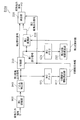
- FIG. 3 is a block diagram showing an example of the configuration of encoding apparatus 100 according to Embodiment 1 of the present invention.
- the encoding device 100 includes a conversion unit 110, a quantization unit 120, and an entropy encoding unit 130.
- the conversion unit 110 generates a converted output signal by converting an input signal (converted input signal). As illustrated in FIG. 3, the conversion unit 110 includes a first conversion unit 200, a division unit 210, a second conversion unit 220, and an integration unit 230.
- the first converter 200 generates a first conversion output signal by performing a first conversion on the conversion input signal using the first conversion matrix.
- the dividing unit 210 divides the first converted output signal into two parts. Specifically, the dividing unit 210 divides the first converted output signal generated by the first converting unit 200 into a first partial signal and a second partial signal using the division integration information.
- the division integration information is an example of selection range information indicating which part of the first converted output signal the first partial signal corresponds to.
- 2nd conversion part 220 generates the 2nd conversion output signal by performing the 2nd conversion to the 1st partial signal using the 2nd conversion matrix.
- the integrating unit 230 generates a converted output signal by integrating the second converted output signal and the second partial signal.
- the quantization unit 120 generates a quantization coefficient by quantizing the conversion output signal generated by the conversion unit 110.
- the entropy encoding unit 130 generates an encoded signal by entropy encoding the quantization coefficient generated by the quantization unit 120.
- an input signal which is various data such as audio data, still image data, and moving image data
- the conversion unit 110 has an encoding target signal (Original Signal) or a prediction error signal that is a difference between the encoding target signal and a prediction signal created based on the previously input encoding target signal.
- a prediction error signal is often input as an object of conversion.However, when prediction is not performed assuming that an error is mixed in the transmission path, or when energy is small, prediction is performed. Instead, the input signal is input as a conversion target.
- Such a transform input signal is represented as a vector xn as shown in Equation 4.
- FIG. 4 is a flowchart showing an example of the operation of the encoding apparatus 100 according to Embodiment 1 of the present invention.
- 5A and 5B are diagrams conceptually illustrating an example of the data flow of conversion section 110 in coding apparatus 100 according to Embodiment 1 of the present invention.
- the conversion unit 110 to convert the converted input signal x n, generates a converted output signal y n (step S110).
- the first conversion unit 200 first generates a first converted output signal y 1 n by performing a first conversion on the converted input signal x n using the first conversion matrix (step S112). . Specifically, the first converter 200 converts the converted input signal x n into the first converted output signal y 1 n so as to reduce the correlation of the converted input signal x n and concentrate the energy in the low frequency band. To do.
- the first conversion coefficient used for the first conversion for example, a coefficient that has already been calculated in the first conversion of the conversion input signal xn that has been input previously can be used. That is, since it is not necessary to calculate the first conversion coefficient every time the first conversion is performed, the amount of calculation required for calculating the first conversion coefficient can be reduced. Specific processing for calculating the first conversion coefficient will be described later.
- the dividing unit 210 divides the first converted output signal y 1 n into a first partial signal y 1L m and a second partial signal y 1H nm (step S114). Specifically, the dividing unit 210 performs the first conversion so that the correlation energy of the first partial signal y 1L m is greater than the correlation energy of the second partial signal y 1H nm based on the division integration information. The output signal y 1 n is divided.
- the division integration information is information that causes the division unit 210 to perform control to divide the low frequency band as the first partial signal y 1L m and the high frequency band as the second partial signal y 1H nm. is there.
- the division integration information is information instructing to dynamically control a component having a large energy to the first partial signal y 1L m and a component having a small energy to the second partial signal y 1H nm according to the input. It may be.
- division integration information for example, division integration information that has already been determined at the time of dividing the first conversion output signal y 1 n previously input can be used. That is, it is not necessary to determine new division integration information every time division is performed.
- the first partial signal y 1L m divided by the dividing unit 210 is rearranged in one dimension and input to the second converting unit 220 as shown in FIG. 5A.
- the second conversion unit 220 performs the second conversion on the first partial signal y 1L m using the second conversion matrix to generate the second conversion output signal y 2 m (step S116). Specifically, the second conversion unit 220 reduces the correlation of the first partial signal y 1L m and concentrates the first partial signal y 1L m on the second converted output signal so as to concentrate energy in a lower frequency band. Convert to y 2 m .
- a coefficient already calculated at the time of the second conversion of the first partial signal y 1L m inputted previously can be used as the second conversion coefficient. That is, since it is not necessary to calculate the second conversion coefficient every time the second conversion is performed, it is possible to reduce the amount of calculation required for calculating the second conversion coefficient. Specific processing for calculating the second conversion coefficient will be described later.
- the integrating unit 230 generates the converted output signal y n by integrating the second converted output signal y 2 m and the second partial signal y 1H nm (step S118). Specifically, the integration unit 230 rearranges the second converted output signal y 2 m to a dimension before being rearranged in one dimension, and the second converted output signal y after the rearrangement based on the division integration information. 2 m and the second partial signal y 1H nm are integrated.
- the quantization unit 120 the converted output signal y n generated as described above by quantization to generate quantized coefficients (step S120).
- the entropy encoding unit 130 generates an encoded signal by entropy encoding the quantization coefficient (step S130).
- the dividing unit 210 may output the first partial signal y 1L m to the second converting unit 220 as it is without rearranging it in a one-dimensional manner.
- the second conversion unit 220 by performing a second transformation to the first partial signal y 1L m two-dimensional, to generate a second conversion output signal y 2 m in two dimensions.
- the second converter 220 performs, for example, non-separable second conversion.
- the integrating unit 230 without performing the reordering of the second conversion output signal y 2 m, to integrate the second conversion output signal y 2 m and a second partial signal y 1H n-m.
- the target of the second conversion is illustrated as an arbitrary region (non-rectangular region) of the first conversion output signal.
- the present invention is not limited to this and may be a rectangular region. I do not care.
- the second conversion unit 220 includes a signal included in a non-rectangular region in the case of a matrix representation including the coefficient value of the low frequency component of the first conversion output signal.
- the second conversion is performed as the first partial signal.
- the second conversion unit 220 uses, as a first partial signal, a signal including a coefficient value included in a rectangular area in the case of matrix expression including a coefficient value of a low frequency component of the first conversion output signal. Two conversions may be performed.
- FIG. 6 is a flowchart showing an example of conversion processing in the conversion unit 110 according to Embodiment 1 of the present invention.
- FIG. 7 is a conceptual diagram showing an example of the derivation of the transform coefficient in the transform unit 110 according to Embodiment 1 of the present invention.
- the conversion unit 110 further includes a first conversion coefficient derivation unit 202 and a second conversion coefficient derivation unit 222.
- the dividing unit 210 and the integrating unit 230 are not shown.
- the first transform coefficient deriving unit 202 determines the first transform coefficient based on the transform input signal xn (step S111).
- the first conversion unit 200 performs the first conversion on the conversion input signal xn using the first conversion matrix configured by the first conversion coefficients determined by the first conversion coefficient derivation unit 202 (step) S112).
- division integration information is determined (step S113).
- the division integration information is read from the memory or the like of the encoding device 100 as long as it controls the division unit 210 to perform predetermined division. Also, the segmentation-concatenation information, as long as it controls the division unit 210 to perform the division corresponding to the first conversion output signal y 1 n, in view of the distribution of energy states based on the first conversion output signal y 1 n To derive the division integration information.
- the dividing unit 210 divides the first converted output signal y 1 n (step S114).
- the second transform coefficient deriving unit 222 determines a second transform coefficient based on the first partial signal y 1L m (step S115).
- the second conversion unit 220 performs the second conversion on the first partial signal y 1 n using the second conversion matrix configured with the determined second conversion coefficient (step S116).
- integrating unit 230, and a second partial signal y IH n-m divided second conversion output signal y 2 m integrates and outputs a conversion output signal y n (step S118).
- the first conversion in the first conversion unit 200 and the second conversion in the second conversion unit 220 will be described in detail with reference to FIG.
- a certain set S A including many samples includes a converted input signal x n input to the first converter 200.
- First conversion coefficient deriving unit 202 for example, using a KLT, determining a first transform coefficients averaged optimized for many samples included in this set S A.
- the first transformation can be performed using a first transformation matrix composed of first transformation coefficients. Therefore, the update frequency of the first transform coefficient can be suppressed, that is, the number of cases where the determination of the first transform coefficient is not performed as in the process shown in FIG. Can do.
- the amount of difference information can be reduced because the amount of change in individual values of the conversion coefficient before and after the update is small. Therefore, when the first transform coefficient is transmitted to the decoding device, an increase in the code amount can be suppressed.
- the second conversion unit 220 receives the first partial signal y 1L m which is a portion having a large correlation energy among the coefficient values constituting the first conversion output signal y 1 n .
- Second conversion coefficient deriving unit 222 like the first conversion coefficient deriving unit 202, for example, using a KLT, comprises a first partial signal y 1L m, less number of samples as compared to the set S A set S C The second transform coefficient that is averagely optimized for the samples included in is obtained.
- the set S A smaller set the set S C, sharply can follow changes in the statistical properties of the first conversion output signal y 1 n inputted, and further the correlation reduction and energy compaction Is possible.
- the update frequency of the transform coefficients by a small set S C is increased, the first partial signal y 1L m, a part of the first conversion output signal y 1 n, dimension than converting the input signal x n Since the number is small, the number of elements of the second transformation matrix is small, and it is possible to achieve both high-efficiency conversion and reduction of the calculation amount and the data amount.
- the second conversion unit 220 receives the first partial signal y 1L m , which is a portion having a large correlation energy, among the coefficient values constituting the first conversion output signal y 1 n . It can be said that a position having a high autocorrelation of the first converted output signal y 1 n is selected. On the other hand, as a similar method, a position having a high cross-correlation of the first converted output signal y 1 n may be selected as the first partial signal y 1L m .
- the division unit 210 and the integration unit 230 perform the dimensional rearrangement for each of the first partial signal y 1L m and the second converted output signal y 2 m .
- the structure which the conversion part 220 performs may be sufficient.
- a conversion input signal x n input to the conversion unit 110. Since these are one-dimensional, these sort processes are unnecessary.
- encoding apparatus 100 performs first conversion on an input signal and performs second conversion on a first partial signal that is a part of the signal after the first conversion. It is characterized by that.
- the encoding apparatus 100 which concerns on Embodiment 1 of this invention, in the conversion using the conversion factor calculated based on the statistical property of an input signal, reduction of the computational complexity of conversion, and a conversion matrix The number of elements (data amount) can be reduced.
- the second conversion by dividing the first conversion output signal y 1 n into a first partial signal y 1L m and the second partial signal y IH n-m, the second conversion Although they will be integrated later, it is not necessary to explicitly divide them. In other words, a portion to be subjected to the second conversion may be determined in the first conversion output signal y 1 n .
- the second conversion by setting the diagonal element of the row for the element that is not subject to the second conversion to 1 and the non-diagonal element to 0, substantially only in the first partial signal y 1L m , A second conversion can be performed.
- FIG. 8 shows a specific example of matrix operation.
- FIG. 9 is a block diagram showing an example of the configuration of the encoding device 100a according to the modification of the first embodiment of the present invention.
- the encoding device 100a includes a conversion unit 110a, a quantization unit 120, and an entropy encoding unit 130.
- symbol is attached
- the conversion unit 110a includes a first conversion unit 200 and a second conversion unit 220a. That is, the conversion unit 110a does not include the division unit 210 and the integration unit 230 as compared with the conversion unit 110 illustrated in FIG. 3, and the second conversion unit 220a instead of the second conversion unit 220. It is different from the point provided with.
- the second conversion unit 220a is a second conversion composed of a second conversion coefficient determined based on the statistical characteristics of the set including the first partial signal y 1L m that is a part of the first conversion output signal y 1 n.
- the second conversion output signal y 2 m is generated by performing the second conversion on the first partial signal y 1L m using the matrix.
- the second conversion unit 220a determines a coefficient value to be subjected to the second conversion among coefficient values constituting the first conversion output signal y 1 n, and a signal configured from the determined coefficient value. Is the first partial signal y 1L m , and the second conversion is performed.
- the second conversion unit 220a outputs a signal including a coefficient value larger than a predetermined threshold value among the plurality of coefficient values constituting the first converted output signal y 1 n to the first partial signal y.
- the second conversion is performed with 1L m .
- the second conversion unit 220a includes a second conversion output signal y 2 m generated, the second partial signal y IH n is a portion other than the first partial signal y 1L m of the first conversion output signal y 1 n and it outputs the converted output signal y n comprising a -m.
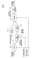
- FIG. 10 is a flowchart showing an example of the operation of the encoding device 100a shown in FIG.
- the conversion unit 110a is to convert the converted input signal x n input, generates a converted output signal y n (step S110a). Specifically, first, with respect to the inputted converted input signal x n, the first conversion unit 200, by performing a first conversion, to generate a first conversion output signal y 1 n (step S112).
- the second conversion unit 220a performs the second conversion on the first partial signal y 1L m (step S116a). For example, the second conversion unit 220a determines, as the first partial signal y 1L m , a portion to be subjected to the second conversion in the first converted output signal y 1 n , and the determined first partial signal y 1L A second transformation is performed on m using a second transformation matrix.
- the quantization unit 120 generates a quantization coefficient C n by quantizing the converted output signal y n including the second converted output signal y 2 m (step S120).
- the entropy encoding unit 130 generates an encoded signal by entropy encoding the quantization coefficient C n (step S130).
- the encoding apparatus 100a also performs an increase in the amount of calculation in the encoding process and the increase in the data amount of the transform coefficient by performing two-stage conversion partially. Can be suppressed.
- the decoding apparatus includes an entropy decoding unit that generates a decoded quantized coefficient by entropy decoding the encoded signal, and a decoding conversion output by dequantizing the decoded quantized coefficient.
- An inverse quantization unit that generates a signal and an inverse transform unit that generates a decoded signal by performing inverse transform on the decoded transform output signal.
- the inverse transform unit performs the second inverse transform on the second decoded transform output signal that is a part of the decoded transform output signal, using the second inverse transform matrix configured by the second inverse transform coefficient, 1st decoding including the 2nd inverse transformation part which generates the 1st decoding partial signal, the 1st decoding partial signal, and the 2nd decoding partial signal which is parts other than the 2nd decoding conversion output signal among decoding conversion output signals
- a first inverse transform unit that generates a decoded signal by performing a first inverse transform on the transformed output signal using a first inverse transform matrix configured with a first inverse transform coefficient;
- the decoding apparatus is characterized by performing a two-step inverse transform on the encoded signal.
- the decoding apparatus provides a second decoded converted output signal that is a part of a decoded converted output signal generated by performing entropy decoding and inverse quantization on the encoded signal. And performing the first inverse transform on the first decoded transform output signal including the signal after the second inverse transform and the second decoded partial signal which is the remaining portion of the decoded transformed output signal.
- FIG. 11A is a block diagram showing an exemplary configuration of decoding apparatus 300 according to Embodiment 2 of the present invention.
- the decoding device 300 receives an encoded signal obtained by encoding audio data or moving image data at a low bit rate, and the decoding device 300 decodes the audio data or moving image data from the encoded signal to thereby generate a decoded signal. Is generated.
- the decoding apparatus 300 performs entropy decoding on the encoded signal, performs inverse quantization, and performs almost the inverse process to the encoding process of performing inverse transform. As illustrated in FIG. 11A, the decoding device 300 includes an entropy decoding unit 310, an inverse quantization unit 320, and an inverse transform unit 330.
- the entropy decoding unit 310 generates a decoded quantized coefficient by entropy decoding the input encoded signal.
- the decoded quantization coefficient corresponds to the quantization coefficient generated by the quantization unit 120 according to Embodiment 1.
- the inverse quantization unit 320 generates a decoded transform output signal by inversely quantizing the decoded quantized coefficient generated by the entropy decoding unit 310.
- the decoded conversion output signal corresponds to the conversion output signal generated by conversion section 110 according to Embodiment 1.
- the inverse conversion unit 330 generates a decoded signal by performing inverse conversion on the decoded conversion output signal generated by the inverse quantization unit 320.
- the decoded signal corresponds to a converted input signal input to converting section 110 according to Embodiment 1.
- FIG. 11B is a block diagram showing an exemplary configuration of inverse transform section 330 in decoding apparatus 300 according to Embodiment 2 of the present invention.
- the inverse transform unit 330 includes a dividing unit 400, a second inverse transform unit 410, an integration unit 420, and a first inverse transform unit 430.
- the dividing unit 400 divides the decoded conversion output signal into two parts. Specifically, the dividing unit 400 divides the decoded transformed output signal generated by the inverse quantization unit 320 into a second decoded transformed output signal and a second decoded partial signal using the division integration information.
- the second decoded conversion output signal corresponds to the second conversion output signal generated by the second conversion unit 220 according to Embodiment 1. That is, the second decoded conversion output signal corresponds to a portion where the second conversion has been performed at the time of encoding, and is a portion to be subjected to the second inverse conversion. Further, the second decoded partial signal corresponds to the second partial signal divided by dividing section 210 according to Embodiment 1.
- the second inverse transform unit 410 generates a first decoded partial signal by performing a second inverse transform on the second decoded transform output signal.
- the first decoded partial signal corresponds to the first partial signal divided by dividing section 210 according to Embodiment 1.
- the integrating unit 420 integrates the first decoded partial signal generated by the second inverse converting unit 410 and the second decoded partial signal to generate a first decoded converted output signal.
- the first decoded conversion output signal corresponds to the first conversion output signal generated by the first conversion unit 200 according to Embodiment 1.
- the first inverse transform unit 430 generates a decoded signal by performing a first inverse transform on the first decoded transform output signal using the first inverse transform matrix.
- the first decoded converted output signal is a signal including the second decoded converted output signal and the second decoded partial signal.
- the decoding apparatus 300 receives an encoded signal generated by encoding a signal that is various data such as audio data, still image data, and moving image data.
- a signal generated by entropy decoding and dequantizing this encoded signal is input to the inverse transform unit 330 as a decoded transform output signal y n .
- the symbol “ ⁇ (hat)” indicates a symbol added on the immediately preceding character, and the symbol “ ⁇ (hat)” is used in the same sense hereinafter.
- FIG. 12 is a flowchart showing an example of the operation of the decoding apparatus 300 according to Embodiment 2 of the present invention.
- 13A and 13B are diagrams conceptually showing an example of the data flow of inverse transform section 330 in decoding apparatus 300 according to Embodiment 2 of the present invention.
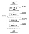
- the entropy decoding unit 310 generates a decoded quantized coefficient by entropy decoding the encoded signal (step S210).
- the inverse quantization unit 320 generates a decoded transform output signal y ⁇ n by inversely quantizing the decoded quantized coefficient (step S220).
- the inverse conversion unit 330 generates a decoded signal x ⁇ n by performing inverse conversion on the decoded conversion output signal y ⁇ n (step S230).
- the dividing unit 400 divides the decoded conversion output signal ⁇ n into two regions based on the division integration information (step S232). That is, the dividing unit 400 divides the decoded converted output signal ⁇ n into a second decoded converted output signal ⁇ 2 m and a second decoded partial signal ⁇ 1H nm .
- the second decoded conversion output signal ⁇ 2 m is a portion to be subjected to the second inverse conversion among a plurality of coefficient values constituting the decoded conversion output signal ⁇ n .
- the division integration information for example, the division integration information used at the time of dividing the decoding conversion output signal y ⁇ n input previously can be used. That is, it is not necessary to determine new division integration information every time division is performed.
- the second decoded transformation output signal y 2 m divided by the dividing unit 400 is rearranged in one dimension and input to the second inverse transformation unit 410 as shown in FIG. 13A.
- the second inverse transform unit 410 generates the first decoded partial signal ⁇ 1L m by performing the second inverse transform on the second decoded transform output signal ⁇ 2 m using the second inverse transform matrix. (Step S234).
- the second inverse transform coefficient for example, a coefficient already determined at the time of the second inverse transform of the previously input second decoded transform output signal y ⁇ 2 m can be used. That is, it is not necessary to determine a new second inverse transform coefficient each time the second inverse transform is performed.
- the integration unit 420 integrates the second decoded partial signal ⁇ 1H nm and the first decoded partial signal ⁇ 1L m to generate the first decoded converted output signal ⁇ 1 n .
- Step S236 the integration unit 420 rearranges the first decoded partial signal y 1 L m to the dimension before being rearranged in one dimension, and the first decoded partial signal after rearrangement based on the division integration information.
- ⁇ 1L m and the second decoded partial signal ⁇ 1H nm are integrated.
- the first inverse transform unit 430 performs the first inverse transform on the first decoded transform output signal ⁇ 1 n using the first inverse transform matrix, thereby generating the decoded signal x n (step S1). S238).
- the first inverse transform coefficient for example, a coefficient already determined at the time of the first inverse transform of the previously input first decoded transform output signal y 1 n can be used. That is, it is not necessary to determine a new first inverse transform coefficient each time the first inverse transform is performed.
- the dividing unit 400 may output the second decoded transformation output signal y ⁇ 2 m to the second inverse transformation unit 410 as it is without rearranging it in one dimension.
- the second inverse transform unit 410 performs the second inverse transform on the two-dimensional second decoded transform output signal y 2 m , thereby generating the two-dimensional first decoded partial signal y 1L m .
- the integrating unit 420 without performing the reordering of the first decoded partial signal y ⁇ 1L m, it integrates a first decoded partial signal y ⁇ 1L m and a second decoded partial signal y ⁇ 1H n-m.
- the target of the second inverse transform is illustrated as an arbitrary region (non-rectangular region) of the decoded transform output signal.
- the present invention is not limited to this and may be a rectangular region. I do not care.
- the second inverse transform unit 410 includes a signal included in the non-rectangular region in the case of matrix representation including the coefficient value of the low frequency component of the decoded transform output signal. Then, the second inverse transformation is performed as the second decoded transformation output signal.
- the second inverse transform unit 410 converts the signal including the coefficient value included in the rectangular area in the case of matrix representation including the coefficient value of the low frequency component of the decoded conversion output signal to the second decoded conversion output signal. As a result, the second inverse transformation may be performed.
- FIG. 14 is a flowchart showing an example of the inverse transform process in the inverse transform unit 330 according to Embodiment 2 of the present invention.
- the dividing unit 400 acquires division integration information (step S ⁇ b> 231). Then, the dividing unit 400 converts the decoded converted output signal y n described above into the second decoded converted output signal y 2 m including the low frequency band and the second decoded partial signal y 1 H including the high frequency band. Divide into nm (step S232). Specifically, the dividing unit 400 has the correlation energy of the second decoded transform output signal y 2 m larger than the correlation energy of the second decoded partial signal ⁇ 1H nm based on the division integration information. In this way, the decoded conversion output signal y n is divided.
- division integration information is the same as that described in the first embodiment, and the acquisition of division integration information may be read out from a predetermined memory or the like, or a decoded conversion output signal it may be dynamically determined in accordance with the y ⁇ 2 m.
- the second inverse transform unit 410 acquires a second inverse transform coefficient used for the second inverse transform (step S233).
- the second inverse transformation matrix configured by the second inverse transformation coefficient is the inverse matrix of the transformation coefficient of the second transformation described in the first embodiment or a matrix approximated thereto.
- This second inverse transform coefficient may be obtained based on the set S D including the second decoded transform output signal ⁇ 2 m using, for example, KLT as in the first embodiment, You may obtain
- the second inverse transform unit 410 performs the second inverse transform on the second decoded transform output signal ⁇ 2 m using the second inverse transform matrix composed of the determined second inverse transform coefficients.
- the first decoded partial signal ⁇ 1L m is generated (step S234).
- the integration unit 420 integrates the first decoded partial signal ⁇ 1L m and the second decoded partial signal ⁇ 1H n ⁇ m to generate the first decoded converted output signal y 1 n ( Step S236).
- the first inverse transform unit 430 acquires a first inverse transform coefficient used for the first inverse transform (step S237).
- the first inverse transformation matrix configured by the first inverse transformation coefficient is the inverse matrix of the transformation coefficient of the first transformation described in the first embodiment or a matrix approximated thereto.
- This first inverse transform coefficient may be obtained based on the set S E including the first decoded transform output signal ⁇ 1 n using, for example, KLT as in the first embodiment, You may obtain
- the first inverse transform unit 430 performs the first inverse transform on the first decoded transform output signal ⁇ 1 n using the first inverse transform matrix composed of the determined first inverse transform coefficients, thereby decoding A signal x ⁇ n is generated (step S238).
- the set S D and the set S E are in the relationship between the set S C and the set S A in the first embodiment, and the set S D is a smaller set with a smaller number of samples than the set S E.
- the decoding apparatus 300 including the inverse transform unit 330 according to Embodiment 2 of the present invention performs high-efficiency conversion, and reduces the amount of computation and data, as in Embodiment 1. Both can be achieved.
- the division unit 400 and the integration unit 420 perform the dimensional rearrangement on each of the second decoded conversion output signal ⁇ 2 m and the first decoded partial signal ⁇ 1L m.
- a configuration in which the second inverse conversion unit 410 performs the replacement may be used. That is, a separation type conversion may be used, or a conversion matrix A 4 including a row of 1 for diagonal elements and 0 for non-diagonal elements as shown in FIG.
- each dimensional signal can be regarded as a one-dimensional signal and is input to the inverse transform unit 330.
- the decoding conversion output signal y ⁇ n is one-dimensional, and the above-described dimension rearrangement (rearrangement to the one-dimensional signal in the dividing unit 400 and rearrangement to the original dimension in the integrating unit 420) is unnecessary. It becomes.
- decoding apparatus 300 provides the second decoded transform output that is a part of the decoded transform output signal generated by performing entropy decoding and inverse quantization on the encoded signal. Performing a second inverse transform on the signal and performing a first inverse transform on the first decoded transform output signal including the signal after the second inverse transform and the second decoded partial signal which is the remaining portion of the decoded transformed output signal It is characterized by.
- decoding apparatus 300 in the inverse transformation using the inverse transformation coefficient calculated based on the statistical properties of the input signal, the amount of transformation computation is reduced and the inverse Reduction of the number of elements of the transformation matrix can be realized. Further, like the encoding device 100 shown in the first embodiment, an encoded signal generated by performing two-stage conversion including conversion using a conversion coefficient calculated based on statistical properties of an input signal is used. It can be decoded correctly.
- the decoded converted output signal y ⁇ n is divided into the second decoded converted output signal y ⁇ 2 m and the second decoded partial signal y ⁇ 1H nm ,
- integration is performed after the second inverse transformation, it is not necessary to explicitly divide. That is, it is only necessary to determine a portion to be subjected to the second inverse transformation in the decoded transformation output signal ⁇ n .
- FIG. 15 is a block diagram showing an exemplary configuration of a decoding apparatus 300a according to a modification of the second embodiment of the present invention.
- the decoding device 300a includes an entropy decoding unit 310, an inverse quantization unit 320, and an inverse transform unit 330a.
- symbol is attached
- the inverse transform unit 330a includes a second inverse transform unit 410a and a first inverse transform unit 430. That is, the inverse conversion unit 330a is not provided with the dividing unit 400 and the integration unit 420 as compared with the inverse conversion unit 330 illustrated in FIG. The difference is that the inverse conversion unit 410a is provided.
- Second inverse transform unit 410a by using a second inverse transformation matrix, a second inverse transform to the second decoded transformed signals y ⁇ 2 m, which is part of the decoded transform output signal y ⁇ n, the One decoded partial signal ⁇ 1L m is generated.
- the second inverse transform unit 410a determines a coefficient value to be subjected to the second inverse transform among the coefficient values constituting the decoded transform output signal ⁇ n, and outputs a signal composed of the determined coefficient value.
- the second inverse transformation is performed as the 2 decoding transformation output signal ⁇ 2 m .
- the second inverse transform unit 410a outputs a signal including a coefficient value having a value larger than a predetermined threshold among a plurality of coefficient values constituting the decoded converted output signal ⁇ n to the second decoded converted output.
- the second conversion is performed as the signal y 2 m .
- the second inverse transform unit 410a may calculate the second inverse transform coefficient to be multiplied by the second decoded partial signal ⁇ 1H nm that is a portion not subjected to the second inverse transformation in the decoded transformed output signal ⁇ n .
- the second inverse transform can be performed substantially only on the second decoded transform output signal ⁇ 2 m .
- FIG. 16 is a flowchart showing an example of the operation of the decoding device 300a shown in FIG.
- the entropy decoding unit 310 generates a decoded quantized coefficient C ⁇ n by entropy decoding the input encoded signal (step S210).
- the inverse quantization unit 320 generates a decoded transform output signal y ⁇ n by inversely quantizing the decoded quantized coefficient C ⁇ n (step S220b).
- the inverse conversion unit 330a generates a decoded signal by inversely converting the decoded conversion output signal y ⁇ n (step S230a). More specifically, first, second inverse transform unit 410a, among the decoded transform output signal y ⁇ n, inversely transforms the second decoded transformed signals y ⁇ 2 m is subject to parts of the second inverse transformation Thus, the first decoded partial signal y 1 L m is generated (S234a). The second inverse transform unit 410a then generates a second decoded partial signal that is a portion that has not been subjected to the second inverse transformation in the generated first decoded partial signal y 1L m and the decoded transformed output signal ⁇ n. A first decoded conversion output signal y ⁇ 1 n including y ⁇ 1H nm is output.
- the first inverse transformation unit 430 by performing the first inverse transformation on the first decoded transformed signals y ⁇ 1 n by using the first inverse transformation matrix to generate a decoded signal x ⁇ n (S238) .
- an encoded signal that has been subjected to two-stage transformation in order to suppress an increase in the calculation amount and an increase in the data amount of the inverse transform coefficient. Can be decrypted.
- An encoding device and an encoding method according to Embodiment 3 of the present invention include a conversion unit that converts a signal to be encoded, such as audio data, still image data, and moving image data, by a combination of a plurality of types of conversions; A conversion method is provided.
- the encoding apparatus and encoding method according to Embodiment 3 of the present invention perform two-stage conversion on a prediction error signal that is a difference between a signal to be encoded (input signal) and a prediction signal as a conversion input signal. It is characterized by performing.
- FIG. 17 is a block diagram showing an example of the configuration of encoding apparatus 500 according to Embodiment 3 of the present invention.
- coding apparatus 500 according to Embodiment 3 of the present invention includes subtractor 505, transform unit 510, quantization unit 120, entropy coding unit 130, and inverse quantization unit 540.
- Note that the same components as those of coding apparatus 100 according to Embodiment 1 shown in FIG. 3 are denoted by the same reference numerals, and description thereof is omitted below.
- the subtracter 505 calculates a difference (prediction error) between the input signal to be encoded and the prediction signal generated from the previous encoding target signal.
- a signal indicating the calculated prediction error is input to the conversion unit 510 as a conversion input signal.
- the conversion unit 510 performs two-stage conversion on the conversion input signal, similarly to the conversion unit 110 described in the first embodiment. That is, the conversion unit 510 performs a first conversion on the converted input signal to generate a first converted output signal, and performs a second conversion on the first partial signal that is a part of the generated first converted output signal. Thus, the second conversion output signal is generated. Then, the conversion unit 510 outputs a converted output signal including the generated second converted output signal and the second partial signal that is a portion other than the first partial signal in the first converted output signal to the quantization unit 120. . Details of the conversion unit 510 will be described later. Here, the conversion unit 510 receives a signal indicating a prediction error image as a conversion input signal.
- the inverse quantization unit 540 generates a decoded conversion output signal by inversely quantizing the quantization coefficient generated by the quantization unit 120.
- the decoded conversion output signal corresponds to the conversion output signal generated by the conversion unit 510.
- the inverse transform unit 550 inversely transforms the decoded conversion output signal generated by the inverse quantization unit 540, thereby generating a decoded conversion input signal.
- the decoded converted input signal corresponds to the converted input signal generated by the subtracter 505.
- the adder 560 generates a decoded signal by adding the decoded conversion input signal generated by the inverse conversion unit 550 and the prediction signal generated from the previous encoding target signal.
- the memory 570 is an example of a storage unit for storing the generated decoded signal.
- the prediction unit 580 generates a prediction signal by predicting the encoding target signal using the decoded signal. Specifically, the prediction unit 580 generates a prediction pixel (prediction signal) of an encoding target block included in an input image that is an encoding target, based on a predetermined encoding parameter. The subtracter 505 generates a prediction error image that is a difference between the pixel of the encoding target block and the prediction pixel.
- Control unit 590 outputs a control signal for controlling the operation of conversion unit 510 based on the local information.
- the local information is, for example, information indicating an index associated with a transform coefficient and division integration information, a prediction mode, or the like.
- the control unit 590 determines conversion coefficients and division integration information based on the local information, and outputs control information indicating the determined coefficients and information to the conversion unit 510.
- the second conversion target of the first conversion output signal is used as the first partial signal in the second conversion based on the control from control unit 590.
- at least one of the second conversion coefficient is determined adaptively in terms of time or space. For example, based on a predetermined encoding parameter, at least one of the range to be subjected to the second conversion and the second conversion coefficient in the first conversion output signal is determined as the first partial signal.
- the memory 570 operates as a delay unit that enables comparison between an encoding target signal and a prediction signal generated from a previous target signal. Since the amount of information is compressed by the quantization process of the quantization unit 120 (information loss occurs), the inverse quantization unit 540 extracts the quantization coefficient to extract the information encoded in the encoded signal. By performing inverse quantization, a decoded conversion output signal is generated, and the inverse conversion unit 550 generates a decoded conversion input signal by performing inverse conversion on the decoded conversion output signal.
- the inverse transformation process of the inverse transformation unit 550 needs to satisfy the relationship between the transformation process of the transformation unit 510 and the inverse transformation.
- the conversion process and the inverse conversion process may not be expressed strictly as a matrix, and the process is reverse to the conversion process of the conversion unit 510.
- the inverse transformation process of the conversion unit 550 may be designed so as not to satisfy a strict inverse transformation relationship.
- the input signal when encoding voice or audio data, the input signal is one-dimensional, and when encoding still image or moving image data, the input signal is two-dimensional.
- FIG. 18 is a flowchart showing an example of the operation of coding apparatus 500 according to Embodiment 3 of the present invention.
- the prediction unit 580 when an encoding target signal (input signal) is input to the encoding device 500, the prediction unit 580 generates a prediction signal using the encoded signal (decoded signal) stored in the memory 570. Then, the subtracter 505 generates a prediction error signal that is an error between the input signal and the prediction signal (step S305). Note that when the input signal is directly converted instead of the prediction error signal, the step of generating the prediction error signal in step S305 is omitted.
- the prediction error signal or input signal generated by the subtractor 505 is input to the conversion unit 510.
- a vector of points input to the transformation, that is, a prediction error signal is defined as a transformation input signal x n (see Equation 4). Since prediction is performed in many compression encodings, the converted input signal xn is often a prediction error, but is not predicted on the assumption that an error is mixed in the transmission path. In some cases, or when the energy is sufficiently small, the signal to be encoded (original signal), that is, the input signal, may be directly input to the conversion without performing prediction.
- Conversion unit 510 a conversion input signal x n, to convert a certain transformation T, which generates conversion output (Transform Output) signal y n (see formula 5) (step S110).
- the conversion output signal (converted output vector) y n is sometimes simply referred to as a coefficient (Coefficient).
- the quantization unit 120 by quantizing the converted output signal y n, and generates a quantization coefficient (Quantized Coefficient) C n (step S120).
- the quantization process performed by the quantization unit 120 is a process of adding the rounding offset a and then dividing it by the uniform quantization step s, and is expressed as Expression 6. a and s are controlled by the encoding apparatus 500 for high-efficiency encoding.
- the entropy encoding unit 130 generates an encoded signal by entropy encoding the quantization coefficient C n (step S130).
- the generated encoded signal is sent to the decoding device.
- the inverse quantization unit 540 generates a decoded transformed output signal y ⁇ n by performing inverse quantization on the quantized coefficient C n as shown in Equation 7 (step S340).
- the decoded transformed output signal y n and the transformed output signal y Does not match n . That is, the decoded transform output signal y ⁇ n, since the distortion due to quantization is mixed, if you predicted before the conversion, the decoded converted output signal y ⁇ n the quantization prediction error It may also be called (Quantized Prediction Error). Even in the case of lossy encoding, when encoding is performed with a sufficient amount of data, information is not lost so much and ⁇ n and y n substantially coincide.
- the inverse transform unit 550 performs the inverse transform T ⁇ 1 on the decoded transform output signal ⁇ n as shown in Equation 8, thereby generating the decoded transform input vector x n n (step S350).
- the adder 560 adds the prediction signal and the decoded conversion input signal to generate a decoded signal. Then, the adder 560 stores the generated decoded signal in the memory 570 so that it can be referred to at the next timing (step S360).
- transformation T and the inverse transformation T ⁇ 1 are expressed by matrix products with transformation matrices A and B having a size of n ⁇ n as shown in Equation 9 and Equation 10, respectively.
- B may not be a strict inverse matrix or a strict transpose matrix of A in order to suppress the amount of computation of the inverse transform T ⁇ 1 in the encoding apparatus 500.
- it may be a transformation A called bi-orthogonal transformation, which is not strictly orthogonal, and its inverse transformation B.
- Equation 11 The matrix product of the transformation matrix A n ⁇ n with respect to the transformation input x n in Equation 9 is expressed by Equation 11.
- the number of multiplications of the transformation matrix and the number of elements of the transformation matrix are n ⁇ 2.
- FIG. 19 is a block diagram showing an example of a detailed configuration of conversion unit 510 according to Embodiment 3 of the present invention.
- the conversion unit 510 includes a first conversion unit 200, a first memory 601, a first conversion coefficient derivation unit 202, a division unit 210, a second memory 611, and a division integration information calculation unit. 612, a second conversion unit 220, a third memory 621, a second conversion coefficient derivation unit 222, and an integration unit 230.
- symbol is attached
- the conversion input signal xn input to the conversion unit 510 is input to the first memory 601 and the first conversion unit 200.
- the first memory 601 is a memory for storing information related to a plurality of converted input signals xn .
- the first transform coefficient deriving unit 202 generates a first transform coefficient constituting the first transform matrix A 1 n used for the first transform T 1 from the information in the first memory 601 and uses the generated first transform coefficient as the first transform coefficient.
- the data is output to the conversion unit 200.
- the first conversion unit 200 uses the first conversion matrix A 1 n configured by the first conversion coefficient calculated by the first conversion coefficient derivation unit 202 for the input conversion input signal x n . by performing the conversion T 1, to generate a first conversion output signal y 1 n.
- the first converted output signal y 1 n is input to the second memory 611 and the dividing unit 210.
- the second memory 611 is a memory for storing information related to a plurality of first converted output signals y 1 n .
- the division integration information calculation unit 612 generates division integration information from the information in the second memory 611, and outputs the generated division integration information to the division unit 210 and the integration unit 230.
- the division integration information is divided such that the low frequency component of the first converted output signal y 1 n is divided into the first partial signal y 1L m and the high frequency component is divided into the second partial signal y 1H nm .
- Control information may be divided such that a component having a large energy is divided into the first partial signal y 1L m and a component having a small energy is divided into the second partial signal y 1H nm .
- the dividing unit 210 divides the first conversion output signal y 1 n into m first partial signals y 1L m and nm second partial signals y 1H nm based on the division integration information. (Where m is a natural number smaller than n). That is, the dividing unit 210 converts the first converted output signal y 1 n composed of n coefficient values, the first partial signal y 1L m composed of m coefficient values, and n ⁇ m coefficients. The second partial signal y 1H nm is divided into numerical values. The first partial signal y 1L m is input to the third memory 621 and the second conversion unit 220. The second partial signal y 1H nm is input to the integration unit 230.
- the third memory 621 is a memory for storing information related to a plurality of first partial signals y 1L m .
- the second transform coefficient deriving unit 222 generates a second transform coefficient that constitutes the second transform matrix A 2 m used for the second transform T 2 from the information in the third memory 621, and uses the generated second transform coefficient as the second transform coefficient.
- the data is output to the conversion unit 220.
- the second conversion unit 220 uses the second conversion matrix A 2 m composed of the second conversion coefficients calculated by the second conversion coefficient derivation unit 222 to convert the first partial signal y 1L m to the second conversion T 2. To generate the second converted output signal y 2 m .
- the integrating unit 230 generates the converted output signal y n by integrating the second converted output signal y 2 m and the second partial signal y 1H nm according to the division integration information. Note that integration is a process opposite to division.
- the second transform coefficient determined by the second transform coefficient deriving unit 222 is a transform coefficient designed optimally for the first partial signal y 1L m .
- the second transformation T 2 using the second transformation matrix A 2 m is a transformation that can reduce the redundancy left in the first transformation output signal y 1 n , and contributes to the compression of the encoded signal. Bring.
- the dividing unit 210 divides the first converted output signal y 1 n , thereby reducing the number of points (number of coefficient values) of the input signal (that is, the first partial signal) to the second converting unit 220. .
- the number of points By reducing the number of points, an effect of reducing the amount of calculation of the second conversion unit 220 and an effect of reducing the total number of conversion coefficients (that is, the amount of data) of the second conversion unit 220 are obtained.
- KLT Kerten-Leve Transform
- the transformation is such that the off-diagonal elements of the variance-covariance matrix of the input signal are 0, which is to solve the eigenvalue problem of the variance-covariance matrix. equal.
- the derived eigenvector becomes a basis function, and the eigenvalue becomes the axis size (that is, energy) of each component of the transform coefficient.
- the conversion coefficients are arranged from a large axis of eigenvalue (dispersion or energy) to a small axis.
- the converted input signal is an n-point vector
- the i-th element (1 ⁇ i ⁇ n) and the j-th (i ⁇ n) of the n-point vectors of the converted output signal Comparing the energy with the element of j ⁇ n), the energy of the i-th element is larger than the energy of the j-th element (the conversion coefficient can be designed to be larger).
- the expressions low frequency band and high frequency band when used, they correspond to an element having a relatively small number and an element having a relatively large number, respectively, and are strictly separated. It does not prescribe where is.
- the main purpose of the present invention is to reduce resources (computation amount and memory usage) related to conversion and inverse conversion, but there is a trade-off relationship between resources and conversion performance in a broad sense. It is set according to the method used and the purpose of the apparatus.
- a plurality of conversions are used for this problem. That is, in the first transformation, transformation is performed using a transformation matrix composed of transformation coefficients that are optimally derived according to the statistical properties of the larger set S A , and in the second transformation, the smaller set S B ( Conversion is performed using a conversion matrix composed of optimally derived conversion coefficients according to the statistical properties of the first converted output signal.
- the encoding apparatus 500 according to Embodiment 3 of the present invention may include a local set determination unit that analyzes the characteristics of the input signal when deriving the second transform coefficient. That is, encoding apparatus 500 according to Embodiment 3 of the present invention may include conversion unit 510a shown in FIG. 20 instead of conversion unit 510. As illustrated in FIG. 20, the conversion unit 510 a includes a local set determination unit 623.
- the local set determination unit 623 analyzes the characteristics of the transform input signal xn and controls the second transform coefficient derivation unit 222 based on the analysis result. Although not shown in FIG. 20, the local set determination unit 623 may control the division integration information calculation unit 612 shown in FIG. Specific processing of the local set determination unit 623 will be described below with reference to FIG.
- FIG. 21 is a diagram conceptually illustrating an example of the derivation of the transform coefficient in the transform unit 510a according to Embodiment 3 of the present invention.
- the converted input signal x n belongs to a large set S A and belongs to one of the smaller sets S B (1) and S B (2) .
- the set S B are shown to be included in the set S A, is converted input signal x n belongs to the set S B, such that does not belong to the set S A, the set S B set A similar derivation method can be applied even when it is not included in SA.
- the first conversion coefficient used by the first conversion unit 200 is generated by the first conversion coefficient derivation unit 202.
- First conversion coefficient deriving unit 202 based on a set S A containing more samples, to optimize the first transformation coefficient.
- the first transform coefficient can be optimized on the average and less sensitive to differences in individual transform inputs. Thereby, the update frequency of the first conversion coefficient can be suppressed. Even when the first transform coefficient is updated, the amount of difference information can be reduced because the change amount of each value of the transform coefficient is small. Therefore, it is possible to reduce the amount of codes when the first transform coefficient is transmitted to the decoding device.
- the second transform coefficient is derived by optimizing the transform input for each of the sets SB (1) and SB (2) .
- the score of the first partial signal to be subjected to the second conversion is reduced by the division than the score of the converted input signal, the amount of calculation and the data amount of the conversion coefficient can be reduced. That is, the input signal to the second conversion unit 220 to be subjected to the second conversion is not the converted input signal xn itself included in the sets S B (1) and S B (2) , but the first converted output signal y. 1 n is a first partial signal y 1L m which is a part of n .
- the local set determination unit 623 detects the statistical variation of the small set by analyzing the characteristics of the converted input signal xn . When the change is detected, a plurality of samples belonging to the small set are determined and notified to the second transform coefficient deriving unit 222. Alternatively, the local set determination unit 623 may determine to which of a predetermined small set the converted input signal xn belongs.
- the input signal (that is, the first partial signal y 1L m ) to the second conversion unit 220 may depend on the prediction signal generation method.
- the local set determination unit 623 uses a prediction signal generation method (prediction signal mode), for example, H.264.
- prediction signal mode for example, H.264.
- the range to be subjected to the second conversion as the first partial signal y 1L m among the plurality of coefficient values constituting the first conversion output signal y 1 n may be determined.
- the local set determination unit 623 determines N small sets in advance, and uses the second partial conversion y 1L m as the first partial signal y 1L m based on an index that evaluates which belongs to the most can reduce the amount of information.
- a target range may be determined.
- the second transform coefficient deriving unit 222 Based on the statistical change instruction detected by the local set determining unit 623, the second transform coefficient deriving unit 222 applies the information amount to the first transformed output signal y 1 n of a plurality of samples belonging to the small set.
- the second transformation coefficient designed to minimize is derived.
- the second conversion coefficient derivation unit 222 calls a conversion coefficient that has been calculated in advance from the memory.
- the division integration information calculation unit 612 determines the division integration information in the same manner as the conversion coefficient.
- the division integration information calculation unit 612 may call the division integration information calculated in advance from the memory.
- the second transform coefficient optimally designed for each of the smaller sets S B (1) , S B (2) (the first transform output signal thereof) can follow the change in statistical properties, and can be used for decorrelation and energy. Gives an extra effect with compression. Furthermore, the second transformation is efficient because the number of dimensions of the input signal is reduced by the dividing unit 210, and therefore the number of elements of the transformation matrix and the amount of computation of the transformation can be reduced.
- the set S B which is a smaller set is a set including the transformed input signal x n in which a local change has occurred.
- the set S B is a set obtained by dividing the set S A locally in the time axis or the spatial domain.
- the set S B is a set having different characteristics when a converted input signal having statistical properties different from the converted input signal x n belonging to the set S A is input for a short time.
- the first transform coefficient is determined based on the large set S A.
- the local set determination unit 623 determines at least one of a transform coefficient and division integration information based on a predetermined encoding parameter.
- the encoding parameter indicates one prediction method among a plurality of predetermined prediction methods.
- the local set determination unit 623 may switch the transform coefficient and the division integration information according to the prediction mode of the intra prediction or the inter prediction that is an example of the encoding parameter. Or you may explicitly multiplex to an encoding stream which is selected from the set of a some transform coefficient and division
- a plurality of prediction modes may be associated with one conversion coefficient and the division integration information. Since the division integration information is information with relatively little change, the type of switching may be less than the conversion coefficient to reduce the memory usage related to the division integration information.
- FIG. 19 illustrates the configuration including the first transform coefficient, the division integration information, the memory for deriving the second transform coefficient, and the deriving unit, these are not necessarily optimal solutions. Any one or all of the above may be derived in advance based on experience or a suboptimal method.
- FIG. 22 is a block diagram showing another example of the conversion unit according to Embodiment 3 of the present invention.
- the conversion unit 510b acquires the first conversion coefficient, the second conversion coefficient, and the division integration information that are derived in advance from the outside, and performs conversion and division based on the acquired coefficients and information.
- the amount of calculation for the high frequency signal is reduced by reducing the multiplication coefficient of the conversion coefficient for the high frequency side signal (that is, reducing the effective accuracy of the conversion coefficient) or zero.
- the dividing unit and the integrating unit do not explicitly appear in the block diagram (see FIG. 9), but it can be said that even a configuration that does not appear corresponds to the configuration of the present invention.
- FIG. 23 is a block diagram illustrating a configuration of an encoding device 500a including the conversion unit 510a illustrated in FIG.
- the encoding apparatus 500a shown in FIG. 23 differs from the encoding apparatus 500 shown in FIG. 17 in that a conversion unit 510a is provided instead of the conversion unit 510 and a control unit 590 is not provided.
- the conversion process flow of the conversion unit 510a according to the modification of the third embodiment of the present invention is the same as that of the first embodiment. Specifically, as shown in FIG. 6, first, the first transform coefficient deriving unit 202 determines the first transform coefficient (step S111). Next, the first conversion unit 200 generates the first conversion output signal by performing the first conversion on the conversion input signal using the first conversion matrix configured with the determined first conversion coefficient (step S1). S112).
- the division integration information calculation unit 612 (not shown) or the local set determination unit 623 determines division integration information (step S113). Then, the dividing unit 210 divides the first converted output signal into a first partial signal and a second partial signal (step S110). At this time, the dividing unit 210 divides the first partial signal so that the correlation energy of the first partial signal is larger than the correlation energy of the second partial signal.
- the local set determining unit 623 analyzes the statistical properties of the local set of the first partial signal, and the second transform coefficient deriving unit 222 determines the second transform coefficient based on the analysis result (step) S115).
- the second conversion unit 220 generates a second converted output signal by performing a second conversion using a second conversion matrix configured with the second conversion coefficient determined for the first partial signal. (Step S116).
- step S118 the integration unit 230 generates a converted output signal by integrating the second partial signal and the second converted output signal.
- step S111, step S113, and step S115 are determined by another method and may not operate as part of the present embodiment.
- the transform coefficient and the division integration information are adaptively changed according to the transform input signal. It is possible to adapt to changes in the statistical properties of the input signal while suppressing the amount of calculation and the data amount of the conversion coefficient.
- FIG. 24A is a block diagram showing an exemplary configuration of an encoding apparatus 500c according to a modification of Embodiment 3 of the present invention.
- the encoding device 500c is different from the encoding device 500a illustrated in FIG. 23 in that a conversion unit 510c is provided instead of the conversion unit 510a and a new memory 624 is provided. Is different.
- the conversion unit 510c is different from the conversion unit 510a in that a second conversion coefficient derivation unit 222c and a local set determination unit 623c are provided instead of the second conversion coefficient derivation unit 222 and the local set determination unit 623. .
- the second transform coefficient derivation unit 222c generates a second transform coefficient based on the derivation control signal output from the local set determination unit 623c.
- the generated second conversion coefficient is stored in the memory 624.
- the memory 624 is an example of a storage unit for storing at least one second conversion coefficient.
- the memory 624 entropy-encodes the second transform coefficient selected from the stored at least one second transform coefficient based on the selection signal output from the local set determination unit 623c and the second transform unit 220. Output to the unit 130.
- the memory 624 stores the index and the second conversion coefficient in association with each other.
- the selection signal is a signal indicating an index
- the memory 624 outputs a second transform coefficient associated with the index indicated by the selection signal.
- the memory 624 stores a plurality of transformation matrices having different sets of coefficient values as second transformation coefficient candidates.
- Index information which is an example of an encoding parameter, is associated one-to-one with a plurality of transformation matrices.
- a conversion matrix specified by the index information indicated by the selection signal is determined as the second conversion coefficient.
- FIG. 25 is a diagram illustrating an example of a correspondence relationship between the second transform coefficient stored in the memory and the divided integration information in the encoding device according to the modification of the third embodiment of the present invention.
- the memory 624 stores the index and the second transform coefficient in association with each other. Further, as shown in FIG. 25, the memory 624 may further store selection range information (here, division integration information) and an index in association with each other.
- the local set determination unit 623c selects either a predetermined conversion coefficient or division integration information based on the characteristics of the input signal or based on the magnitude of the estimated value of the compressed information amount.
- a selection signal for selecting whether to use is output.
- the memory 624 Based on the output selection signal, the memory 624 outputs a predetermined conversion coefficient to the second conversion unit 220.
- the division integration information is output to the division unit 210 and the integration unit 230 (not shown in FIG. 24A).
- the selection signal is subjected to compression of the information amount as necessary (for example, outputting a difference signal from the prediction index predicted from the index of the neighboring neighboring block), and is multiplexed into the encoded signal by the entropy encoding unit 130. Is done.
- the local set determination unit 623c may output a derivation control signal that instructs the second transform coefficient derivation unit 222c to derive a new second transform coefficient. At this time, the newly derived second transform coefficient is stored in the memory 624. Further, the local set determination unit 623c may cause the division integration information calculation unit (not shown) to calculate new division integration information by outputting a derivation control signal. Note that the calculation of the division integration information may be performed by the second transform coefficient deriving unit 222c.
- the information amount of the new second transform coefficient and the division integration information is compressed as necessary, and is multiplexed into the encoded signal by the entropy encoding unit 130.
- encoding apparatus 500c according to the modification of Embodiment 3 shown in FIG. 24A outputs the second transform coefficient and the division integration information to the decoding apparatus.
- the second transform coefficient stored in the decoding device can be selected on the decoding device side by transmitting a selection signal indicating an index instead of outputting the second transform coefficient itself.
- the converted input signal is a difference between the input signal and the prediction signal, and thus depends on the characteristics of the prediction signal. Since the characteristics of the transformed input signal may be different depending on whether the predicted signal is well predicted or not, the local set determining unit 623c determines the second transformation coefficient according to the magnitude of the transformed input signal. And division integration information may be switched.
- FIG. 24B is a block diagram showing an exemplary configuration of coding apparatus 500d according to a modification of Embodiment 3 of the present invention.
- the encoding device 500d includes a conversion unit 510d instead of the conversion unit 510c and a prediction control unit 585, as compared with the encoding device 500c illustrated in FIG. 24A. Is different. Also, the conversion unit 510d is different from the conversion unit 510c in that a local set determination unit 623d is provided instead of the local set determination unit 623c.
- the prediction control unit 585 determines the prediction mode signal, outputs it to the prediction unit 580, and outputs it to the local set determination unit 623d.
- the prediction mode signal compresses the amount of information, for example, by taking a difference from the estimated value from the information of neighboring blocks, if necessary, and is multiplexed into the encoded signal by the entropy encoding unit 130.
- the local set determination unit 623d outputs a selection signal for selecting a predetermined transform coefficient and division integration information based on the prediction mode signal. Based on the selection signal, the memory 624 outputs a predetermined second conversion coefficient to the second conversion unit 220 and the division integration information to the division unit 210 and the integration unit 230.
- the local set determining unit 623d may output a derivation control signal that instructs the second transform coefficient deriving unit 222c to derive a new second transform coefficient.
- the newly derived second transform coefficient is stored in the memory 624.
- the local set determination unit 623d may cause the division integration information calculation unit (not shown) to calculate new division integration information by outputting a derivation control signal. Note that the calculation of the division integration information may be performed by the second transform coefficient deriving unit 222c.
- the information amount of the new second transform coefficient and the division integration information is compressed as necessary, and is multiplexed into the encoded signal by the entropy encoding unit 130.
- the local set determination unit 623d may switch between the second conversion coefficient and the division integration information according to the size of the conversion input signal.
- the prediction may be inter-frame prediction (inter prediction) or intra-frame prediction (intra prediction).
- the intra-frame prediction may be a method of predicting by extrapolating encoded (decoded) neighboring pixels in a predetermined direction.
- the division integration information can perform division integration optimized for the angle based on the angle of the prediction method that generated the prediction signal (a predetermined extrapolation angle in the case of intra-frame prediction). It may also be determined. The concept of the division integration information will be described with reference to FIGS. 26A to 26C.
- FIG. 26A shows the first converted output signal of the 4 ⁇ 4 block, and the upper left shows an example of the low frequency band.
- further compression is performed by performing a second conversion on the first partial signal, with the low-frequency side where energy tends to concentrate as the first partial signal and the other high-frequency portion as the second partial signal.
- Gij ⁇ 0, 1 ⁇ , (i is the vertical downward direction, j is the horizontal right direction, and ij is the part to which the N ⁇ N elements of the first converted output signal belong. It is defined as 1) starting point, 0 if it belongs to the first partial signal, and 1) if it belongs to the second partial signal.
- FIG. 26B is a conceptual diagram illustrating an example of selecting division integration information based on a prediction direction of intra prediction from a plurality of division integration information.
- the division integration information is designed in units of angles obtained by dividing the range from 0 to ⁇ [rad] into several, with the upper right direction as the base point of the angle.
- FIG. 26B is an example in which four pieces of division integration information are defined.
- S 0 design angle is level, assuming that the power is concentrated to the left (DC in the horizontal direction), a and preferentially 0 (i.e., the first partial signal) G0j.
- G0j i.e., the first partial signal
- FIG. 26C is an example of preparing 8 types of angles, that is, 8 types of division integration information, when selecting 4 elements of the 4 ⁇ 4 block as the first partial signal. As shown in this example, a relationship can be defined between the position of the angle and the coefficient value constituting the first partial signal, and the position of the coefficient value constituting the first partial signal is determined at an arbitrary angle. can do.
- the predetermined direction A range including the coefficient value is determined as a second conversion target.
- the range including the coefficient value in the predetermined direction is a range including the coefficient value on the start point side in the predetermined direction, that is, the coefficient value on the start point side in the extrapolation direction.
- the encoding parameter indicates a prediction method indicating extrapolation in a substantially horizontal direction (right direction)
- the coefficient value in the horizontal direction (specifically, among a plurality of coefficient values constituting the first converted output signal)
- the left side coefficient value) is determined as the second conversion target.
- the coefficient value in the vertical direction (specifically, among the plurality of coefficient values constituting the first converted output signal)
- the upper coefficient value) is determined as the second conversion target.
- m coefficient values closer to the starting point side in the extrapolation direction are selected from n coefficient values constituting the first conversion output signal. Determine the coefficient value. More specifically, the upper left coefficient value and the coefficient value close to the start point side in the extrapolation direction are included.
- m coefficient values are targeted for the second transformation.
- m coefficient values are determined so as to include an upper left coefficient value, a coefficient value close to the start point side in the extrapolation direction, and a coefficient value along the extrapolation direction.
- the second partial signal of S 7 is the same as the coefficient value ((1, 1)) at the upper left, as in S 6.
- the upper coefficient values ((1, 2) and (1, 3)) and the coefficient value ((2, 1)) along the extrapolation direction (lower left direction) are included.
- the decoding apparatus and decoding method according to the fourth embodiment of the present invention are encoded signals obtained by encoding signals such as audio data, still image data, and moving image data (for example, generated in the first or third embodiment).
- An inverse transform unit and an inverse transform method for performing inverse transform on a coded signal) by a combination of a plurality of types of transforms are provided.
- the decoding apparatus and decoding method according to Embodiment 4 of the present invention perform two-stage inverse transform on a signal obtained by encoding a prediction error signal that is a difference between a signal to be encoded (input signal) and a prediction signal. It is characterized by performing.
- FIG. 27 is a block diagram showing an example of the configuration of the decoding apparatus 700 according to Embodiment 4 of the present invention.
- a decoding apparatus 700 according to Embodiment 4 of the present invention includes an entropy decoding unit 310, an inverse quantization unit 320, an inverse transform unit 730, a control unit 740, an adder 750, A memory 760 and a prediction unit 770 are provided.
- the same components as those of decoding apparatus 300 according to Embodiment 2 shown in FIG. 11A are denoted by the same reference numerals, and description thereof is omitted below.
- the inverse transform unit 730 performs a reverse transform on the decoded transform output signal generated by the inverse quantization unit 320 to generate a decoded transform input signal. Specifically, the inverse transform unit 730 performs two-stage inverse transform on the decoded transform output signal. Note that, based on the control signal from the control unit 740, the inverse transform coefficient used for the inverse transform and the position of division (the portion to be subjected to the second inverse transform) are determined. Details of the inverse transform unit 730 will be described later.
- the control unit 740 outputs a control signal for controlling the operation of the inverse transform unit 730 based on the local information.
- the local information is an example of an encoding parameter, and is information indicating, for example, an index associated with an inverse transform coefficient and division integration information, or a prediction mode used at the time of encoding.
- the control unit 740 determines the inverse transform coefficient and the division integration information based on the local information, and outputs control information indicating the determined coefficient and information to the inverse transform unit 730.
- the adder 750 adds the decoded conversion input signal generated by the inverse transform unit 730 and the prediction signal generated by the prediction based on the decoded signal generated from the previous encoded signal, thereby adding the decoded signal. Generate.
- the memory 760 is an example of a storage unit for storing the generated decoded signal.
- the prediction unit 770 generates a prediction signal by performing prediction based on a decoded signal generated from a previous encoded signal. That is, the prediction unit 770 generates a prediction signal based on the decoded signal stored in the memory 760. For example, the prediction unit 770 generates a prediction pixel (prediction signal) of a decoding target block included in the prediction error image based on the encoding parameter. Then, the prediction pixel generated by the prediction unit 770 and the pixel of the decoding target block are added by the adder 750 to restore the input image (decoded signal).
- the inverse transform unit 730 may acquire the second inverse transform coefficient and the division integration information from the encoding device. Note that what is acquired from the encoding device is the second transform coefficient, and the second inverse transform coefficient may be obtained from the second transform coefficient.
- the division integration information is an example of selection range information indicating which part of the decoded converted output signal the second decoded converted output signal corresponds to.
- the second inverse transform of the decoded transform output signals is used as the second decoded transform output signal in the second inverse transform based on the control from control section 740.
- At least one of the target range and the second inverse transform coefficient is determined adaptively in terms of time or space. For example, based on a predetermined encoding parameter, at least one of the range to be subjected to the second inverse transform and the second inverse transform coefficient in the decoded transform output signal is determined as the second decoded transform output signal.
- FIG. 28 is a flowchart showing an exemplary operation of the decoding apparatus 700 according to Embodiment 4 of the present invention.
- the prediction unit 770 generates a prediction signal based on the decoded signal stored in the memory 760 (step S405). Note that this step S405 is omitted when the encoded signal generated by the encoding method for directly converting the input signal is decoded.
- the entropy decoding unit 310 generates a quantized coefficient by entropy decoding the input encoded signal (step S210).
- the inverse quantization unit 320 inversely quantizes the quantization coefficient to generate a decoded conversion output signal y ⁇ n (step S220).
- inverse transform unit 730 by inverse transforming the decoded transform output signal y ⁇ n, and generates a decoded conversion input signal x ⁇ n (step S230). Specifically, as illustrated in FIG. 12 or FIG. 14, the inverse transform unit 730 performs a two-step inverse transform to generate a decoded transform input signal x ⁇ n .
- the inverse transformation in the inverse transformation unit 730 means the transformation in the decoding device, and is not limited to the inverse transformation of the transformation in the encoding device.
- the adder 750 generates a decoded signal by adding the decoded conversion input signal x ⁇ n and the prediction signal.
- the decoded signal is output as an output signal of the entire decoding apparatus 700.
- the decoded signal is stored in the memory 760 (step S440), and is referred to when the subsequent encoded signal is decoded. That is, the memory 760 operates as a delay unit.
- the output signal is one-dimensional, and the output signal is two-dimensional in the still picture and moving picture decoding apparatus.
- a decoding apparatus (or operation mode) that directly outputs a decoded signal without performing prediction can be exemplified except for the prediction unit 770 and the memory 760.
- FIG. 29 is a block diagram illustrating an exemplary configuration of the inverse transform unit 730 according to Embodiment 4 of the present invention.
- the inverse transform unit 730 includes a dividing unit 400, a second inverse transform unit 410, an integration unit 420, and a first inverse transform unit 430.
- the inverse conversion unit 730 receives the decoded conversion output signal y ⁇ n .
- the decoded converted output signal y ⁇ n corresponds to the converted output signal y n of the conversion unit 510 shown in FIG. 17 was produced.
- the dividing unit 400 divides the decoded converted output signal ⁇ n into a second decoded converted output signal and a second decoded partial signal according to the divided integration information.
- the second inverse transform unit 410 generates the first decoded partial signal by inversely transforming the second decoded transform output signal using the second inverse transform matrix.
- the integration unit 420 integrates the second decoded partial signal and the first decoded partial signal according to the division integration information, thereby generating a first decoded conversion output signal.
- the first inverse transform unit 430 generates a decoded transformed input signal by inversely transforming the first decoded transformed output signal using the first inverse transformed matrix. Note that the decoded converted input signal corresponds to the converted input signal input to the converting unit 510 shown in FIG.
- the division integration information is equivalent to that described in the above-described embodiment, the number of dimensions of the input to the division unit 400 (decoding conversion output signal) is n, and the input to the second inverse conversion unit 410 (second decoding).
- the number of dimensions of the converted output signal) is m (natural number where m ⁇ n).
- the number of dimensions at the time of input to the second inverse transform unit 410 is n, and the second inverse transform unit 410 has a diagonal element of 1 and a non-diagonal element of 0 as shown in FIG. it may be using the transformation matrix a 4 containing the line.
- the second conversion unit may be a separation type.
- the second inverse transformation matrix used for the second inverse transformation has an inverse matrix of the transformation matrix of the second transformation described in the first or third embodiment or an approximate relationship of the inverse matrix.
- the first inverse transformation matrix used for the first inverse transformation has an inverse matrix of the first transformation matrix described in the first or third embodiment or an approximate relationship of the inverse matrix.
- the effective accuracy of the first inverse transform coefficient and the second inverse transform coefficient may be lowered.
- the embodiment is based on the first inverse transform coefficient described in the second embodiment or the present embodiment. It is preferable to derive the first transform coefficient described in 1 or 3 and similarly derive the second transform coefficient based on the second inverse transform coefficient.
- the second inverse transform coefficient, the first inverse transform coefficient, and the division integration information are multiplexed into the encoded signal and notified from the encoding device to the decoding device.
- it may be notified without being multiplexed with the encoded signal using another transmission channel, or may be notified by a transmission / storage format.
- it may be notified as a specified value of a standard or a profile level of the standard, or may be notified based on information obtained by both the decoding device and the encoding device.
- the division unit 400 acquires division integration information (step S ⁇ b> 231). Then, division section 400 divides the decoded converted output signal into the second decoded converted output signal and the second decoded partial signal according to the acquired divided integration information (step S232).
- the second inverse transform unit 410 acquires the second inverse transform coefficient (step S233). Then, the second inverse transform unit 410 generates the first decoded partial signal by performing the second inverse transform on the second decoded transform output signal (step S234).
- the integration unit 420 generates a first decoded conversion output signal by integrating the first decoded partial signal and the second decoded partial signal according to the division integration information (step S236).
- the first inverse transform unit 430 acquires the first inverse transform coefficient (step S237). Then, the first inverse transform unit 430 performs a first inverse transform on the first decoded transform output signal, thereby generating a decoded transform input signal (step S238).
- step S231 for acquiring the division integration information, step S232 for acquiring the inverse transform coefficient, and step S234 are not necessarily performed at the timing of this flow because there are many notification variations as described above. not an essential operation as part of the present embodiment.
- the decoding apparatus and the decoding method according to Embodiment 4 of the present invention can adapt to changes in the statistical properties of the input signal while suppressing the amount of conversion processing and the amount of inverse transform coefficients.
- an encoded signal generated by performing two-stage conversion including conversion using a conversion coefficient calculated based on the statistical properties of an input signal as in encoding apparatus 500 shown in the third embodiment. It can be decoded correctly.
- FIG. 30 is a block diagram showing an example of a configuration of a decoding device 700a according to Embodiment 4 of the present invention.
- the decoding device 700a is different from the decoding device 700 shown in FIG. 27 in that it newly includes memories 781 and 782.
- the memory 781 stores the second inverse transform coefficient in association with the index.
- the memory 782 stores division integration information used for division and integration in association with indexes.
- the memory 781 stores a plurality of transformation matrices having different sets of coefficient values as candidates for the second inverse transformation matrix.
- Index information which is an example of an encoding parameter, is associated one-to-one with a plurality of transformation matrices.
- the coefficient of the transformation matrix specified by the index information indicated by the selection signal is determined as the second inverse transformation coefficient.
- the memories 781 and 782 select and output the inverse transform coefficient and the division integration information to the inverse transform unit 730 based on the selection signal output from the entropy decoding unit 310, respectively.
- the selection signal is, for example, a signal indicating an index, and an inverse transform coefficient and division integration information associated with the index indicated by the selection signal are output.
- the entropy decoding unit 310 extracts the compressed selection signal by entropy decoding the encoded signal, and decodes the selection signal from the compressed selection signal. Then, the entropy decoding unit 310 outputs the decoded selection signal to the memory 781 and the memory 782. From each of the memories 781 and 782, the second inverse transform coefficient and the division integration information are output to the inverse transform unit 730.
- This selective mechanism is applied in time and space, and may be performed in block units, macro block units, a unit in which a plurality of macro blocks are combined, or a slice unit based on a selection signal. Moreover, you may perform adaptively combining the in-plane prediction mode and a selection signal. Note that the total number of non-zero coefficients of the decoded quantized coefficients, the total number of non-zero coefficients in the low frequency region, the sum of the levels of the non-zero coefficients, the total sum of the decoded transform output signals y ⁇ output from the inverse quantization unit 320, the low frequency The second inverse transform coefficient and the division integration information may be switched according to the total area.
- FIG. 31 is a block diagram showing an exemplary configuration of decoding apparatus 700b according to Embodiment 4 of the present invention.
- the decoding device 700b is different from the decoding device 700a shown in FIG. 30 in that a selection signal determination unit 790 is newly provided.
- the selection signal determination unit 790 acquires the prediction mode signal output from the entropy decoding unit 310, and generates a selection signal based on the acquired prediction mode signal.
- the selection signal is, for example, a signal indicating an index. From the memories 781 and 782, an inverse transform coefficient and division integration information associated with the index indicated by the selection signal are output to the inverse transform unit 730.
- the entropy decoding unit 310 takes out the compressed prediction mode signal by entropy decoding the encoded signal, and decodes the prediction mode signal in combination with the estimated value from the information of the neighboring blocks.
- the prediction mode signal is output to the prediction unit 770, and the prediction unit 770 generates a prediction signal.
- the prediction mode signal is sent to the selection signal determination unit 790, and the selection signal determination unit 790 outputs a selection signal for selecting an inverse transform coefficient and division integration information corresponding to the prediction mode signal.
- the selection signal is output to the memory 781 and the memory 782, and the second inverse transform coefficient and the division integration information are output to the inverse transform unit 730 from each memory.
- This selective mechanism is applied in time and space, and may be performed in block units, macro block units, a unit in which a plurality of macro blocks are combined, or a slice unit based on a selection signal. Further, the selection signal corresponding to the prediction mode signal described in FIG. 31 may be combined with the selection signal decoded from the encoded signal described in FIG.
- the second inverse transform coefficient and the division integration information may be switched according to the sum of the two.
- the second inverse transform coefficient and the division and integration information may be switched based on the parity (even or odd state) of the sum of the decoded quantized coefficients. Note that when the sum of the decoded quantized coefficients is 1, the second inverse transform may not be performed.
- a range including the coefficient value in the predetermined direction is determined as a target of the second inverse transformation.
- the range including the coefficient value in the predetermined direction is a range including the coefficient value on the start point side in the predetermined direction.
- the encoding parameter indicates a prediction method indicating extrapolation in a substantially horizontal direction
- the coefficient value in the horizontal direction (specifically, the coefficient value on the left side of the plurality of coefficient values constituting the decoded transform output signal).
- a range including a) determining as the target of the second inverse transformation.
- the coefficient value in the vertical direction (specifically, the coefficient value on the upper side among the plurality of coefficient values constituting the decoded conversion output signal) ) Is determined as the second inverse transformation target.
- An encoding apparatus and an encoding method according to Embodiment 5 of the present invention include a conversion unit that converts a signal to be encoded, such as audio data, still image data, and moving image data, by combining a plurality of types of conversions; A conversion method is provided.
- the encoding apparatus and the encoding method according to Embodiment 5 of the present invention are characterized in that the first conversion is performed using a fixed conversion matrix composed of predetermined fixed conversion coefficients.
- the same components as those in the above-described embodiment are denoted by the same reference numerals, and description thereof may be omitted.
- FIG. 32 is a block diagram showing an example of the configuration of conversion section 810 according to Embodiment 5 of the present invention.
- the encoding apparatus according to Embodiment 5 of the present invention differs from Embodiment 1 or 3 only in the configuration of the conversion unit, the configuration and operation of the conversion unit will be described below. .
- the conversion unit 810 includes a first conversion unit 200, a division unit 210, a second conversion unit 220, an integration unit 230, a second memory 611, a division integration information calculation unit 612, A third memory 621 and a second transform coefficient deriving unit 222 are provided.
- the conversion unit 810 includes a first conversion unit 900 instead of the first conversion unit 200, a first memory 601, and a first conversion coefficient derivation unit 202. It differs in that it does not provide.
- the conversion input signal is input to the first conversion unit 900.
- the first conversion unit 900 generates a first conversion output signal by performing a first conversion on the conversion input signal using a conversion matrix composed of predetermined conversion coefficients and / or basis functions.
- the first conversion unit 900 abandons the degree of freedom in which a conversion coefficient can be arbitrarily taken and limits the conversion to a specified conversion. Thereby, the complexity of processing can be reduced and the amount of calculation can be reduced.
- such conversion is referred to as fixed conversion.
- FIG. 32 shows the configuration including the division integration information, the memory for deriving the second transform coefficient, and the deriving unit.
- it may not be a perfect optimal solution. Any one or all of these may be derived in advance based on experience or a suboptimal method.
- the conversion unit 810 by using a plurality of conversion, as the first transformation, transformed using the fixed conversion as a second conversion, the smaller the set S B (first conversion output A transformation is performed using a transformation matrix composed of transformation coefficients that are optimally derived according to the statistical properties of the signal.
- first conversion output A transformation is performed using a transformation matrix composed of transformation coefficients that are optimally derived according to the statistical properties of the signal.
- the first conversion coefficient is designed in advance so as to be optimal based on the statistical properties of the set S A when the set S A is very large.
- the set S A By designing the set S A to be very large, it is possible to eliminate the need to update the conversion coefficient of the first conversion unit 900 and to perform fixed conversion. Therefore, since there is no degree of freedom to take different conversion coefficients for the input signal, the conversion unit 810 does not need to include the first memory 601 and the first conversion coefficient derivation unit 202 described in the third embodiment.
- the conversion of the existing standard may be used as the first conversion.
- discrete cosine transform equipped with MPEG-1 / 2/4 video coding standard An integer precision DCT adopted by the H.264 / AVC standard may be used. These conversions can take a butterfly configuration, and the number of multiplications for an n-dimensional input can be reduced to n ⁇ Log 2 (n) (n ⁇ n in the case of the first conversion of Embodiment 3).
- the conversion of an existing standard is strictly might not optimized for very large set S A containing transformed input signal.
- the input signal to the encoder has a special correlation due to the influence of the characteristics of the image sensor, etc., or when the converted input signal has a prediction error, the predicted signal has a special correlation. Another reason is that the converted input signal has a special correlation.
- Such correlation can be compensated by performing decorrelation and energy compression in the second conversion by reflecting the second conversion coefficient in designing each embodiment when designing.
- a set obtained by converting the set S B (1) by the first conversion unit 900 is set as a set SC (1)
- the set S B (2) is set as the first set.
- the set converted by the 1 conversion unit 900 is set as a set SC (2) .
- the second transform coefficient deriving unit 222 derives the second transform coefficient independently of each of the sets S C (1) and S C (2) .
- the second conversion unit 220 is configured such that only a part of the signal is input by the dividing unit 210, the performance of decorrelation and energy compression is slightly reduced as compared with the third embodiment.
- it is not necessary to calculate the first transform coefficient so that it is possible to reduce the amount of calculation.
- it is not necessary to provide a memory and a derivation unit for deriving the first transform coefficient it is possible to reduce the size of the circuit.
- step S111 in FIG. 6 is omitted, and the processes of steps S112 to S118 are executed.
- step S115 since the first conversion is an existing conversion and is not optimally designed for the first conversion input signal, it is reflected by optimization of the conversion coefficient of the second conversion (step S115). Note that step S113 and step S115 are determined by another method and may not operate as part of the present embodiment.
- the encoding device and the encoding method according to Embodiment 5 of the present invention can adapt to changes in the statistical properties of the input signal while suppressing the amount of conversion processing and the amount of conversion coefficient data. Furthermore, the amount of calculation can be reduced by using fixed conversion.
- H. As a fixed conversion, H. In some cases, such as integer precision DCT adopted by H.264 / AVC standard, variables composed of shift and addition without using multiplication do not have the same base size (norm) of the transformation matrix. Therefore, when a fixed conversion is used as the first conversion, it is preferable to correct the norm.
- FIG. 34 is a block diagram showing an example of the configuration of the conversion unit 810a according to the modification of the fifth embodiment of the present invention.
- the conversion unit 810a further includes a norm correction unit 940 as compared with the conversion unit 810.
- the norm correction unit 940 performs norm correction on the first conversion output signal generated by the first conversion unit 900. Then, the norm-corrected signal is output to the dividing unit 210. The norm correction unit 940 corrects the first conversion output signal by normalizing the first conversion output signal using the correction parameter determined based on the first conversion matrix.
- the correction parameter is, for example, the norm of the first transformation matrix.
- the norm correction unit 940 corrects the input first conversion output signal y 1 n using the norm calculated from the first conversion matrix A 1 n used for the first conversion.
- the norm is calculated by the following expression 12.
- a (i, k) is an element included in the first transformation matrix A 1 n .
- the norm correction unit 940 calculates the norm, and corrects the first converted output signal y 1 n using the calculated norm. To do.
- the norm correction unit 940 may hold the norm in an internal memory or the like.
- the norm correction unit 940 corrects the first converted output signal y 1 n according to Equation 13. That is, the norm correction unit 940 generates a corrected first converted output signal y ′ 1 n by multiplying the first converted output signal y 1 n by the inverse of the norm. In other words, the norm correction unit 940 generates the corrected first conversion output signal y ′ 1 n by dividing the first conversion output signal y 1 n by the norm.
- the norm correction unit 940 multiplies the element y 1 (i) of the first converted output signal y 1 n by the inverse of the norm N (i), thereby correcting the element of the corrected first converted output signal y ′ 1 n .
- the norm correction described above may be performed separately for the first partial signal and the second partial signal after being divided by the dividing unit 210.
- FIG. 35 is a block diagram showing an example of the configuration of the conversion unit 810b according to the modification of the fifth embodiment of the present invention.
- the conversion unit 810b further includes norm correction units 941 and 942 as compared with the conversion unit 810.
- the norm correction unit 941 performs norm correction on the first partial signal y 1L m . Then, the first partial signal y ′ 1L m after the norm correction is output to the second conversion unit 220. Specifically, the norm correction unit 941 corrects the input first partial signal y 1L m using the norm N calculated from the first conversion matrix A 1 n used for the first conversion (see Equation 13). , Y ′ 1 (i) is read as y ′ 1L (i), and y 1 (i) is read as y 1L (i)). The norm N is calculated by the above equation 12.
- the norm correction unit 942 performs norm correction on the second partial signal y 1H nm . Then, the second partial signal y ′ 1H nm after the norm correction is output to the integration unit 230. Specifically, the norm correction unit 942 corrects the input second partial signal y 1H nm using the norm N calculated from the first conversion matrix A 1 n used for the first conversion (formula 13, y ′ 1 (i) is read as y ′ 1H (i), and y 1 (i) is read as y 1H (i)). The norm N is calculated by the above equation 12.
- the norm correction unit 941 derives a correction coefficient by correcting the second conversion coefficient constituting the second conversion matrix A 2 m using the norm calculated from the first conversion matrix A 1 n .
- the norm is calculated by Equation 12.
- the norm correction unit 941 corrects the second conversion coefficient constituting the second conversion matrix A 2 m according to Equation 14. That is, the norm correction unit 941 generates a corrected second conversion matrix A ′ 2 m by multiplying the second conversion matrix A 2 m by the inverse of the norm. In other words, the norm correction unit 941 generates a corrected second conversion coefficient that is a correction coefficient by dividing the second conversion coefficient by the norm.
- the norm correction unit 941 generates the corrected second conversion coefficient a ′ 2 (i, j) by multiplying the second conversion coefficient a 2 (i, j) by the inverse of the norm N (i). .
- the second conversion unit 220 generates the second converted output signal y 2 m by converting the first partial signal y 1L m using the corrected second conversion matrix A ′ 2 m .
- the bases of the conversion matrix can be made uniform, and the conversion accuracy can be improved.
- norm correction is performed and H.
- the weight scale weights 264 in the quantization matrix which has been performed by the quantization unit (QMatrix), the above norm correction unit 940 (or the norm correcting unit 941 and 942) may be performed.
- the weight scale of the quantization matrix is an example of a correction parameter.
- the norm correction unit 940 corrects the first converted output signal y 1 n by weighting the first partial signal using the quantization matrix used in the quantization unit 120. Specifically, the norm correction unit 940 corrects the first converted output signal y 1 n according to Equations 15 and 16. That is, the norm correction unit 940 generates the corrected first converted output signal y ′ 1 n by multiplying the first converted output signal y 1 n by the inverse mf of the quantization matrix. In other words, the norm correction unit 940 generates the corrected first converted output signal y ′ 1 n by dividing the first converted output signal y 1 n by the quantization matrix.
- f (i) is the value of each element of the weight scale derived from the quantization matrix.
- post-scale correction is preferably further performed after the second conversion.
- the conversion output signal y n is generated by multiplying the signal y ′ n output from the integration unit 230 by the correction coefficient mf_2 calculated from the quantization matrix. Specifically, the converted output signal y n is generated by correcting the signal y ′ n after integration according to the equations 17 and 18.
- Equation 19 S (i) is an element of the matrix expressed by Equation 19.
- the post-scale correction described above may be performed on the second conversion output signal generated by the second conversion unit 220.
- the second transformation matrix A 2 m may be corrected instead of the first partial signal y 1L m in the weighting of the quantization matrix weight scale.
- the norm correction unit 941 corrects the second transformation matrix A 2 m using the quantization matrix. Specifically, the norm correction unit 941 corrects the second transformation matrix A 2 m according to Equation 20. As shown in Expression 20, the norm correction unit 941 performs the inverse of the quantization matrix element mf (i) and the correction coefficient mf_2 calculated from the quantization matrix for each second transformation coefficient a 2 (i, j). Multiply with (j).
- the effect of improving the coding efficiency can be obtained in the same manner by correcting the second transformation matrix A 2 m instead of the first partial signal y 1L m .
- the norm correction and the quantization matrix weighting may be combined. That is, the norm correction unit 941 may perform both norm correction and quantization matrix correction on the first partial signal y 1L m or the second transformation matrix A 2 m .
- the norm correction unit 941 corrects the first partial signal y 1L m according to Equation 21. Specifically, the norm correction unit 941 calculates the inverse of the norm N (i) calculated from the first transformation matrix A 1 n and the quantization for each element y 1L (i) of the first partial signal y 1L m .
- the corrected first partial signal y ′ 1L m is generated by multiplying the inverse of the matrix element mf (i).
- the norm correction unit 941 corrects the second conversion matrix A 2 m according to Equation 22. Specifically, the norm correction unit 941 calculates the inverse of the norm N (i) calculated from the first transformation matrix A 1 n and the elements of the quantization matrix for each second transformation coefficient a 2 (i, j). Is multiplied by the correction coefficient mf_2 (j) calculated from the quantization matrix to generate a corrected second transformation matrix A ′ 2 m .
- the first conversion output signal is corrected by shifting down the coefficient value constituting the first partial signal input to the second conversion unit 220 so that the effective data length in the second conversion falls below a predetermined value. May be. Thereby, the required accuracy of the internal processing of the second conversion unit 220 can be reduced, and circuit resources can be saved.
- bit length of the coefficient value constituting the first partial signal before the first conversion or the first partial signal after the second conversion is the bit length of the coefficient value constituting the second partial signal.
- the coefficient values constituting the first partial signal or the second converted output signal may be shifted down so as to be the same as.
- a decoding apparatus and a decoding method according to Embodiment 6 of the present invention are encoded signals obtained by encoding signals such as audio data, still image data, and moving image data (for example, the encoding generated in Embodiment 5).
- the decoding apparatus and decoding method according to Embodiment 6 of the present invention are characterized in that the first inverse transformation is performed using an inverse transformation matrix composed of predetermined fixed inverse transformation coefficients.
- the same components as those in the above-described embodiment are denoted by the same reference numerals, and description thereof may be omitted.
- FIG. 36 is a block diagram showing an example of the configuration of the inverse transform unit 1030 according to Embodiment 6 of the present invention. Note that the decoding apparatus according to Embodiment 6 of the present invention differs from Embodiment 2 or 4 only in the configuration of the inverse transform unit, and therefore the configuration and operation of the inverse transform unit will be described below. To do.
- the inverse transform unit 1030 includes a dividing unit 400, a second inverse transform unit 410, an integration unit 420, and a first inverse transform unit 1130.
- the inverse transform unit 1030 is different from the inverse transform unit 730 illustrated in FIG. 29 in that a first inverse transform unit 1130 is provided instead of the first inverse transform unit 430.
- the first inverse transform unit 1130 performs a predetermined fixed inverse transform process on the first decoded transform output signal to generate a decoded transform input signal. Since the first inverse transform unit 1130 performs a fixed inverse transform that is determined in advance, it is not necessary to acquire the first (inverse) transform coefficient from the outside (for example, an encoding device).
- the first inverse transform unit 1130 is, for example, a discrete cosine transform equipped with an MPEG-1 / 2/4 video encoding standard,
- the integer precision DCT using the H.264 / AVC standard may be used as the first inverse transform to reduce the amount of calculation.
- step S237 in FIG. 14 is omitted, and the processes of steps S231 to S236 and S238 are executed.
- step S231 for obtaining the division integration information and step S233 for obtaining the second inverse transform coefficient are not necessarily performed at the timing of this flow because there are many notification variations as described above. This is not an essential operation as part of this embodiment.
- the decoding device and the decoding method according to Embodiment 6 of the present invention can adapt to changes in the statistical properties of the input signal while suppressing the amount of conversion processing and the amount of inverse transform coefficients. Further, by using the fixed conversion can reduce the amount of calculation.
- the base size (norm) of the inverse transform matrix may not be uniform. Therefore, it is preferable to correct the norm when an inverse transform with irregular norms is used as the first inverse transform.
- the norm correction processing is performed in the inverse quantization unit.
- the input signal to the first inverse transform unit 1130 is used as the input signal. Against. That is, after the second inverse transform is performed, the first decoded transform output signal is corrected.
- FIG. 37 is a block diagram showing an example of the configuration of the inverse transform unit 1030a according to the modification of the sixth embodiment of the present invention.
- the inverse transform unit 1030a further includes a norm correction unit 1140 as compared with the inverse transform unit 1030.
- the norm correction unit 1140 generates a first decoded conversion output signal by performing norm correction on the signal including the first decoded partial signal and the second decoded partial signal integrated by the integrating unit 420.
- the norm correction unit 1140 corrects the first decoded transform output signal by normalizing the first decoded partial signal using a correction parameter determined based on the first inverse transform matrix.
- the correction parameter is, for example, the norm of the first inverse transformation matrix.
- the norm correction unit 1140 corrects the combined signal y ⁇ ′ 1 n using the norm calculated from the first inverse transformation matrix A ⁇ 1 1 n .
- the norm is calculated according to Equation 12 as in the fifth embodiment.
- the correcting unit 1140 calculates a norm and corrects the signal y ⁇ ′ 1 n after integration using the calculated norm.
- the norm correction unit 1140 may hold the norm in an internal memory or the like.
- the norm correction unit 1140 performs a process opposite to that of the norm correction unit 940 according to the modification of the fifth embodiment. Specifically, the norm correction unit 1140, as shown in Equation 23, by multiplying the signal y ⁇ 'norm 1 n after integration, to produce a first decoded transformed signals y ⁇ 1 n.
- the multiplication shown in Expression 23 is performed for each element included in the integrated signal y ⁇ ′ 1 n . That is, the norm correction unit 1140 multiplies the element y ⁇ ' 1 (i) of the integrated signal y ⁇ ' 1 n by the norm N (i), thereby obtaining the element of the first decoded conversion output signal y ⁇ 1 n . y ⁇ 1 (i) is generated.
- the norm correction described above may be separately performed on the second decoded partial signal and the first decoded partial signal which are two input signals before integration by the integration unit 420.
- FIG. 38 is a block diagram showing an example of the configuration of the inverse transform unit 1030b according to the modification of the sixth embodiment of the present invention.
- the inverse transform unit 1030b further includes norm correction units 1141 and 1142 compared to the inverse transform unit 1030.
- the norm correction unit 1141 performs norm correction on the first decoded partial signal y ⁇ ′ 1L m . Specifically, the norm correction unit 1141 uses the norm N calculated from the first inverse transformation matrix A ⁇ 1 1 n used for the first inverse transformation to convert the input first decoded partial signal y ⁇ ′ 1L m . (Refer to Equation 23, y ⁇ 1 (i) is read as y ⁇ 1L (i), and y ⁇ ' 1 (i) is read as y ⁇ ' 1L (i)).
- the norm N is calculated by the above equation 12.
- the norm correction unit 1142 performs norm correction on the second decoded partial signal y ⁇ ′ 1H nm . Specifically, the norm correction unit 1142 uses the norm N calculated from the first inverse transformation matrix A ⁇ 1 1 n used for the first inverse transformation to input the second decoded partial signal y ⁇ ′ 1H n ⁇ . m is corrected (see Equation 23, y ⁇ 1 (i) is replaced with y ⁇ 1H (i), and y ⁇ ' 1 (i) is replaced with y ⁇ ' 1H (i)).
- the integrating unit 420 generates the first decoded conversion output signal by integrating the first decoded partial signal and the second decoded partial signal that have been subjected to norm correction.
- the norm N is calculated by the above equation 12.
- the norm correction unit 1141 corrects the second transformation coefficient using the norm calculated from the first inverse transformation matrix A ⁇ 1 1 n .
- the norm is calculated by Equation 12. Specifically, the norm correction unit 1141 corrects the second inverse transform coefficient according to Equation 24. That is, the norm correction unit 1141 generates the corrected second inverse transform coefficient by multiplying the second inverse transform coefficient by the norm.
- the second inverse transform unit 410 inversely transforms the second decoded transform output signal ⁇ 2 m using the corrected second inverse transform matrix A ⁇ 1 ′ 2 m , so that the first decoded partial signal ⁇ 1L m is generated.
- the basis of the inverse transformation matrix can be made uniform, and the accuracy of the transformation can be improved.
- the configuration in FIG. 37 has an effect that the implementation can be simplified because the norm correction unit is single.
- the configuration of FIG. 38 has an effect of realizing a norm correction unit having minimum effective accuracy corresponding to each effective accuracy when the effectiveness of two signals is different.
- the weight scale weighting processing of the quantization matrix (Qmatrix), which was performed by the inverse quantization unit, may be performed by the norm correction unit shown in FIG. That is, the first decoded conversion output signal may be corrected by weighting the first decoded partial signal using the weight scale of the quantization matrix.
- the norm correction unit 1140 performs a process opposite to the process performed by the norm correction unit 940 according to the modification of the fifth embodiment. Specifically, the norm correction unit 1140 generates the first decoded conversion output signal y 1 n by multiplying the integrated signal y ⁇ ′ 1 n by a quantization parameter. Note that this is equivalent to dividing the integrated signal y ⁇ ′ 1 n by the correction coefficient mf as shown in Equation 25.
- the correction coefficient mf is expressed by Equation 16.
- the second decoded conversion output signal y ⁇ 2 m is generated by multiplying the second decoded conversion output signal y ⁇ 2 m by the inverse of the correction coefficient mf_2 calculated from the quantization matrix. To do. Note that this is equivalent to dividing the second decoded conversion output signal y ⁇ 2 m by the correction coefficient mf_2 as shown in Expression 26.
- correction coefficient mf_2 (j) is expressed by Expression 18 and Expression 19.
- the weighting of the quantization matrix weight scale also corrects the second inverse transformation matrix A ⁇ 1 2 m , not the second decoded transformation output signal y ⁇ ′ 1L m after the inverse transformation. May be.
- the norm correction unit 1141 corrects the second inverse transformation matrix A ⁇ 1 2 m using the quantization matrix. Specifically, the norm correction unit 1141 corrects the second inverse transformation matrix A ⁇ 1 2 m according to Equation 27. As shown in Equation 27, the norm correction unit 1141 is calculated from the inverse number mf (i) of the quantization matrix element and the quantization matrix for each second inverse transform coefficient a ⁇ 1 2 (i, j). Divide by the correction coefficient mf_2 (j).
- the norm correction unit 1141 performs both norm correction and weighting of the quantization matrix on the second decoded conversion output signal y ⁇ ′ 1L m or the second inverse conversion matrix A ⁇ 1 2 m after the inverse conversion. Also good.
- the norm correction unit 1141 calculates from the first inverse transformation matrix A ⁇ 1 1 n for each element y ⁇ ′ 1L (i) of the second decoded transformed output signal y ⁇ ′ 1L m after the inverse transformation.
- the first decoded partial signal y 1 L m is generated by multiplying the obtained norm N (i) and dividing the inverse mf (i) of the quantization matrix element.
- the norm correction unit 1141 corrects the second inverse transformation matrix A ⁇ 1 2 m according to Equation 29. Specifically, the norm correction unit 1141 multiplies the norm N (i) calculated from the first inverse transformation matrix A ⁇ 1 1 n for each second transformation coefficient a ⁇ 1 2 (i, j), By dividing the reciprocal number mf (i) of the quantization matrix by the correction coefficient mf_2 (j) calculated from the quantization matrix, a corrected second inverse transformation matrix A -1 ' 2 m is generated.
- the norm correction processing and the weight scale weighting processing are omitted to reduce the amount of calculation, and only when the amount of data of the converted input signal is small May be performed. Note that the norm correction processing and the weight scale weighting are limited to the case where the correction target signal is non-zero, and the amount of calculation may be reduced.
- the data size of the memory necessary for accurately expressing the numerical value (here, the required bit length) is generally increased by matrix operation.
- the second decoded partial signal is not subjected to the second inverse transform, while the first decoded partial signal is multiplied by the second inverse transform unit 410, so that the required bit length may be different. Therefore, when the required bit length increases by M bits in the second inverse transform unit 410, the second decoded partial signal may be shifted up by M bits.
- the configuration of FIG. 36 it is not necessary to switch the first inverse transform unit 1130 by performing the correction to match the bit lengths before the input to the first inverse transform unit 1130, and the first inverse transform unit
- the configuration of 1130 can be simplified.
- FIG. 37 by performing the correction to match the required bit length at a time prior to entering the norm correction unit 1140, the processing of the norm correcting unit 1140, and a second decoding portion signal, first decoder It is not necessary to switch to the partial signal, and the configuration of the norm correction unit 1140 can be simplified.
- the norm correction unit 1142 to which the second decoded partial signal is input keeps the required bit length required for internal signal processing low because the required bit length of the input signal remains low. , Circuit resources can be saved. Alternatively, only the low required bit length of the input signal frequency is multiplied in norm correcting unit 1142, the norm correction amount, and may increase the effective precision of the weight scale weighting amount, in this case, the norm correction and weight scale The calculation accuracy with weighting can be improved.
- the second decoded conversion output signal input to the second inverse transform unit 410 may be shifted down by N bits in advance, thereby reducing the required accuracy of internal processing of the second inverse transform unit 410 and saving circuit resources.
- N may be set smaller than M. In this case, when an N-bit shift down is performed at the time of input to the second inverse transform, an MN bit shift down is performed on the output of the second inverse transform.
- the coefficient value constituting the second decoded transform output signal input to the second inverse transform unit 410 is shifted down so that the effective data length in the second inverse transform falls within a predetermined value. You may correct
- first decoded partial signal or the first decoded partial signal or the second decoded converted output signal so that the bit length of the coefficient value constituting the second decoded partial signal is the same as the bit length of the coefficient value constituting the second decoded partial signal.
- the coefficient values constituting the second decoded conversion output signal may be shifted down.
- bit length of the bit operation described in this embodiment may be controlled in sequence units, GOP units, frame units, or block units.
- the bit length in units of blocks based on the effective bit length of the block of the second decoding conversion output signal (the size that actually consumes the memory at a certain moment).
- the calculation accuracy can be improved. For example, when the effective bit length of the block of the second decoding conversion output is long, the shift down amount before the input to the second inverse conversion unit 410 is increased, and otherwise, the block to the second inverse conversion unit 410 is increased.
- the shift down amount before input may be reduced.
- the first transformation and the first inverse transformation may be configured to switch between discrete cosine transformation and discrete sine transformation.
- the switching flag information is multiplexed with the encoded signal in the encoding device, decoded in the decoding device, and notified from the encoding device to the decoding device. Since the discrete cosine transform and the discrete sine transform are transforms whose phases are shifted to each other pi / 2, the second transform and the second inverse transform coefficient have a relationship shifted by pi / 2 from each other, and are reversed. You may reduce the information content of a conversion coefficient.
- An encoding apparatus and an encoding method according to Embodiment 7 of the present invention include a conversion unit that converts a signal to be encoded, such as audio data, still image data, and moving image data, by a combination of a plurality of types of conversions; A conversion method is provided.
- the encoding apparatus and encoding method according to Embodiment 7 of the present invention are characterized by performing separation-type and non-separation-type conversion on multidimensional signals.
- the same components as those in the above-described embodiment are denoted by the same reference numerals, and description thereof may be omitted.
- the converted input signal, the first converted output signal, the second partial signal, and the converted output signal are P (P is an integer of 2 or more) dimensional signals.
- the second conversion unit 220 may be either for inputting / outputting a P-dimensional signal or for inputting / outputting a one-dimensional signal.
- the second conversion unit 220 inputs and outputs a one-dimensional signal, the second conversion unit 220 is the same as in the first, third, and fifth embodiments.
- the dividing unit 210 divides the P-dimensional conversion input signal into the first partial signal and the second partial signal according to the division integration information, and further rearranges the first partial signal in one dimension.
- the rearrangement order information is additionally stored in the division integration information.
- the integrating unit 230 generates a conversion output signal by integrating the second conversion output signal and the second partial signal according to the division integration information. At this time, the integration unit 230 rearranges the second conversion output signal, which is a one-dimensional signal, into a P-dimensional signal based on the rearrangement information stored in the division integration information, and then the P-dimensional second conversion output signal. And the P-dimensional second partial signal. In addition, when the 2nd conversion part 220 inputs / outputs a P-dimensional signal, it does not need to rearrange to a one-dimensional signal.
- the second conversion unit 220 may perform separation type conversion (two-stage conversion in the horizontal axis direction and the vertical axis direction). That is, the second conversion unit 220 performs conversion in units of rows in the horizontal direction and performs conversion in units of columns in the vertical direction. The horizontal and vertical order may be reversed.
- the conversion in units of rows or columns having one element is equivalent to not performing substantial processing, the processing may be skipped, or the norm correction processing in the subsequent stage may be performed here. Good.
- the conversion coefficient for row conversion and the conversion coefficient for column conversion may be the same or different.
- the conversion coefficient of row conversion may reduce the data amount of conversion coefficient by using the same conversion coefficient in all rows, and adapt to the difference in statistical properties of row units by using different conversion coefficients for each row. The conversion performance may be improved.
- the column conversion is similar to the row conversion, and the same conversion coefficient may be used for all the columns, or different conversion coefficients may be used.
- the P-dimensional signal is a non-separable type in which the P-dimensional signal is rearranged in a one-dimensional manner at the time of conversion input, or a separate type configuration in which processing is performed in a one-dimensional unit inside the conversion.
- the multiplication processing of the coefficient may be reduced.
- the coefficient set to zero is a low energy element as described above.
- the dividing unit 210 receives a signal (first partial signal) input to the second conversion unit 220 and a signal not input (second partial signal). ) Is no longer necessary. Therefore, the integration unit 230 is not necessary.
- the diagonal element is 1 and the non-diagonal element is set for the row of the transformation matrix corresponding to the element that is not the second transformation target.
- the diagonal element may be characterized by using a conversion matrix of 0 to reduce multiplication processing for elements that are not the target of the second conversion.
- the line not corresponding to the second conversion may be a line corresponding to a low energy element in the first conversion output. Or you may set the element of the conversion matrix corresponding to the element with a small cross correlation of a 1st conversion output to zero.
- the second conversion unit 220 generates a second converted output signal by performing a second conversion on the first partial signal using the second conversion matrix.
- the integrating unit 230 integrates the second converted output signal and the second partial signal, and outputs the result as a converted output signal.
- the first conversion unit 200 performs a first conversion on each of the P-dimensional input signals (for example, a plurality of two-dimensional conversion input signals) to generate a plurality of first conversion output signals.
- the first conversion output signal may be generated by applying the P-1 dimensional first conversion a plurality of times as shown in FIG. 39 to the conversion input signal which is a P dimensional signal.
- the first conversion unit 200 performs the 4 ⁇ 4 two-dimensional first conversion twice on the 4 ⁇ 4 ⁇ 2 three-dimensional conversion input signal.
- two first conversion units 200 are shown for ease of explanation, but one first conversion unit 200 may perform two-dimensional first conversion twice. Further, the conversion unit may actually include two first conversion units 200, and the two first conversion units 200 may perform the two-dimensional first conversion once each.
- the first conversion unit 200 may perform the first P-dimensional conversion once for the P-dimensional conversion input signal.
- the first transformation in the P dimension may be a separation type or a non-separation type.
- the second transformation second conversion unit 220 performs.
- the second conversion unit 220 collectively performs a second conversion on a batch signal including a plurality of first partial signals that are a part of the plurality of first conversion output signals.
- FIG. 40 is a diagram conceptually showing the data flow of the second conversion having the separation type configuration.
- the second conversion unit 220 converts the two-dimensional signal in the horizontal direction (S501).
- the second conversion unit 220 performs conversion in the vertical direction (S502).
- the second conversion unit 220 performs conversion in a direction across blocks (S503).
- This order is an example, and the order of processing in the horizontal, vertical, and cross-block directions is not limited to this.
- the second inverse transformation of the separation type configuration performs the inverse transformation in the order of the horizontal direction, the vertical direction, the direction across blocks, and the like, as in FIG. The order of the inverse transform is also not limited to this.
- the second conversion unit 220 performs the separation-type second conversion for performing the one-dimensional conversion P times for each of the P dimensions, and the P-dimensional first partial signal. To do.
- the separation-type second conversion in which the one-dimensional conversion is performed three times for each of the three dimensions is performed on the three-dimensional first partial signal.
- the input signal input to the encoding apparatus is, for example, an image signal corresponding to each of a plurality of blocks constituting an input image or a prediction error image.
- the plurality of blocks include a luminance block or a color difference block of the input image or the prediction error image.
- the plurality of blocks may include blocks spatially adjacent to each other in the input image or the prediction error image, as shown in FIG.
- the first transform coefficient deriving unit 202 determines the first transform coefficient (step S111).
- the 1st conversion part 200 produces
- the first conversion may be performed a plurality of times in a dimension lower than the dimension of the input signal.
- the division integration information calculation unit 612 determines division integration information (step S113).
- the dividing unit 210 divides the first converted output signal into a first partial signal and a second partial signal based on the division integration information (step S114). At this time, the dividing unit 210 divides the first partial signal so that the correlation energy of the first partial signal is larger than the correlation energy of the second partial signal.
- the second transform coefficient deriving unit 222 determines the second transform coefficient based on the statistical properties of the local set of the first partial signals (step S115). And the 2nd conversion part 220 produces
- the integration unit 230 generates a converted output signal by integrating the second converted output signal and the second partial signal (step S118).
- step S111 is omitted. Note that step S111, step S113, and step S115 are determined by another method and may not operate as part of the present embodiment.
- the second conversion is a separation type, the dividing unit 210 rearranges the first partial signal from the P dimension to the one dimension in step S114, and the integrating unit 230 outputs the second conversion output signal in step S118. Are rearranged from the first dimension to the P dimension, and then integrated.
- the multi-dimensional conversion input signal may be a luminance signal (Y signal) and a color difference signal (U signal, V signal).
- FIG. 41 is a diagram conceptually illustrating an example of a data flow when the multidimensional conversion input signal is a YUV signal.
- the luminance signal (Y signal) and the two color difference signals (U signal and V signal) are subjected to a first three-dimensional conversion at the same time in the first conversion unit 200, or individually two-dimensional first conversion. Is done.
- the second conversion unit 220 is a first low-frequency region having high energy among the first conversion output signal of the Y signal, the first conversion output signal of the U signal, and the first conversion output signal of the V signal. A second conversion is performed on the partial signal to generate a second converted output signal. At this time, the second conversion unit 220 performs the second conversion on the plurality of second conversion output signals in the order shown in FIG. 40, for example.
- the 2nd conversion output signal and the 2nd partial signal which is the field where the 2nd conversion was not applied are unified, and a conversion output signal is generated.
- the Y signal converted output signal, the U signal converted output signal, and the V signal converted output signal are individually scanned and quantized.
- the second converted output signal may be scanned and quantized independently of the second partial signal.
- the multidimensional conversion input signal may be an image signal of spatially adjacent blocks.
- FIG. 42 is a diagram conceptually illustrating an example of a data flow in a case where a multidimensional conversion input signal is a signal of a block that is spatially adjacent.
- a plurality of small blocks (four in the example shown in FIG. 42) that are spatially adjacent are first converted individually by the first converter 200.
- the second conversion unit 220 performs the second conversion on the first partial signal that is a low-frequency region including a high-energy element among the respective first conversion output signals, and thereby performs the second conversion.
- a conversion output signal is generated.
- the second conversion unit 220 performs the second conversion on the plurality of second conversion output signals in the order shown in FIG. 40, for example.
- the small block transform output signals are individually scanned and quantized.
- the second converted output signal may be scanned and quantized independently of the second partial signal.
- the encoding apparatus and the encoding method according to Embodiment 7 of the present invention can adapt to changes in the statistical properties of the input signal while suppressing the amount of conversion processing and the amount of data of conversion coefficients. .
- it is effective for P-dimensional (P is an integer of 2 or more) input signals.
- the second conversion unit 220 may perform non-separable second conversion. That is, the second conversion unit 220 rearranges the P-dimensional signal into a one-dimensional signal, and performs non-separable second conversion for converting the rearranged signal into the rearranged signal, on the P-dimensional first partial signal. May be. Specifically, since it is the same as that described in the first embodiment, the description is omitted here.
- the decoding apparatus and decoding method according to the eighth embodiment of the present invention provides an encoded signal obtained by encoding a signal such as audio data, still image data, or moving image data (for example, the encoding generated in the seventh embodiment).
- the decoding apparatus and decoding method according to Embodiment 8 of the present invention are characterized by performing separation-type and non-separation-type inverse transforms on multidimensional signals.
- the same components as those in the above-described embodiment are denoted by the same reference numerals, and description thereof may be omitted.
- the decoded conversion output signal, the decoded conversion input signal, the decoded signal, and the prediction signal are P-dimensional signals (P is an integer of 2 or more). That is, the decoded converted output signal, the second decoded partial signal, the first decoded converted output signal, and the decoded converted input signal are P-dimensional signals.
- the second inverse transform unit 410 may be either for inputting / outputting a P-dimensional signal or for inputting / outputting a one-dimensional signal. When the second inverse transform unit 410 inputs and outputs a one-dimensional signal, the second inverse transform unit 410 is the same as in the second, fourth, and sixth embodiments.
- the dividing unit 400 After dividing the P-dimensional signal into the second decoded conversion output signal and the second decoded partial signal according to the division integration information, the dividing unit 400 further rearranges the second decoded conversion output signal in one dimension. Rearrangement order information is additionally stored in the division integration information.
- the integration unit 420 generates a first decoded conversion output signal by integrating the first decoded partial signal and the second decoded partial signal according to the division integration information. At this time, the integration unit 420 rearranges the first decoded partial signal, which is a one-dimensional signal, into a P-dimensional signal based on the rearrangement information stored in the divided integration information, and then the P-dimensional first decoded partial signal. And the P-dimensional second decoded partial signal. In addition, when the 2nd inverse transformation part 410 inputs / outputs a P-dimensional signal, it does not need to rearrange to a one-dimensional signal.
- Conceptual diagram of the data flow in this case is in Figure 13B.
- the second inverse conversion unit 410 may perform a separation type (two-stage conversion in the horizontal axis direction and the vertical axis direction).
- a conceptual diagram of the data flow in this case is shown in FIG. That is, the second inverse conversion unit 410 performs inverse conversion in units of rows in the horizontal direction and performs inverse conversion in units of columns in the vertical direction. The horizontal and vertical order may be reversed.
- the processing may be skipped, or the norm correction processing in the subsequent stage may be performed here.
- the row conversion inverse conversion coefficient and the column conversion inverse conversion coefficient may be the same or different.
- the inverse transformation coefficient of row transformation may reduce the data amount of the inverse transformation coefficient by using the same inverse transformation coefficient for all rows, and use different inverse transformation coefficients for each row, The conversion performance may be improved by adapting to the difference in characteristics.
- the column transformation is the same as the row transformation, and the same inverse transformation coefficient may be used for all the columns, or different inverse transformation coefficients may be used.
- the P-dimensional signal is a non-separable type in which the P-dimensional signal is rearranged one-dimensionally at the time of input of the inverse transformation, or a separation-type configuration in which processing is performed in one-dimensional units inside the inverse transformation.
- the multiplication processing of the coefficient may be reduced.
- the coefficient set to zero is a low energy element as described above.
- the signal input to the second inverse transform unit 410 (second decoded transform output signal) and the signal not input in the dividing unit 400 it becomes unnecessary to divide the (second decoding portion signal) and. Therefore, the integration unit 420 is not necessary.
- a plurality of non-zero coefficients may be set as the second inverse transform coefficient to reduce multiplication processing related to the coefficient.
- the zero coefficient may be set at a position where the energy is small or only a coefficient having a small cross-correlation.
- the diagonal element is 1 in the base where all the non-diagonal elements are 0.
- FIG. 44 is a diagram conceptually showing the data flow of the inverse transform unit according to Embodiment 8 of the present invention.
- the second inverse transform unit 410 performs the second inverse transform on the second decoded transform output signal using the second inverse transform matrix composed of the second inverse transform coefficients, thereby obtaining the first decoded partial signal.
- the second inverse transform unit 410 includes a batch signal including a second decoded transform output signal (in the example of FIG. 44, two two-dimensional second decoded transform output signals) corresponding to a part of the plurality of encoded signals.
- a plurality of first decoded partial signals are generated by collectively performing the second inverse transform.
- the integrating unit 420 generates a first decoded conversion output signal by integrating the first decoded partial signal and the second decoded partial signal. Then, the first inverse transform unit 430 performs the first inverse transform on the first decoded transform output signal using the first inverse transform matrix configured by the first inverse transform coefficient, thereby converting the decoded transform input signal. Generate. That is, the first inverse transform unit 430 performs decoding by performing first inverse transform on each of the first decoded transform output signals including each of the plurality of first partial signals and the corresponding second decoded partial signal. A converted input signal is generated.
- the second inverse transform unit 410 performs inverse transform in the order of the horizontal direction, the vertical direction, the direction across blocks, and the like, as in FIG.
- the order of the inverse transform is not limited to this.
- the first inverse transform unit 430 may generate the decoded transform input signal by applying the P-1 dimensional first inverse transform a plurality of times as shown in FIG. For example, in the example illustrated in FIG. 44, the first inverse transform unit 430 performs the 4 ⁇ 4 two-dimensional first inverse transform twice on the 4 ⁇ 4 ⁇ 2 three-dimensional first decoded transform output signal. Do.
- FIG. 44 shows two first inverse transformation unit 430
- one of the first inverse transformation unit 430 may perform a first conversion of two dimensional.
- the conversion unit may actually include two first inverse conversion units 430, and the two first inverse conversion units 430 may perform the first two-dimensional conversion once each.
- the first inverse transformation unit 430 may perform the first P-dimensional transformation once on the P-dimensional transformation input signal.
- the first transformation in the P dimension may be a separation type or a non-separation type.
- the second inverse transform unit 410 performs the separation-type second inverse transform in which the one-dimensional transformation is performed P times for each of the P dimensions. Decode converted output signal. That is, in the example shown in FIG. 44, the separation-type second inverse transformation that performs the one-dimensional transformation three times for each of the three dimensions is performed on the three-dimensional second decoded transformation output signal (see FIG. 40).
- the encoded signal input to the decoding apparatus according to Embodiment 8 of the present invention is, for example, a signal obtained by encoding an image signal corresponding to each of a plurality of blocks constituting an input image or a prediction error image. is there.
- the plurality of blocks include a luminance block or a color difference block of the input image or the prediction error image.
- the plurality of blocks may include blocks spatially adjacent to each other in the input image or the prediction error image, as shown in FIG.
- division unit 400 acquires division integration information (step S231).
- division section 400 divides the decoded conversion output signal into the second decoded conversion output signal and the second decoded partial signal according to the division integration information (step S232).
- the second inverse transform unit 410 acquires the second inverse transform coefficient (step S233). Then, the second inverse transform unit 410 generates the first decoded partial signal by performing the second inverse transform on the second decoded transform output signal (step S234).
- the integration unit 420 generates a first decoded conversion output signal by integrating the first decoded partial signal and the second decoded partial signal according to the division integration information (step S236).
- the first inverse transform unit 430 acquires the first inverse transform coefficient (step S237). Then, the first inverse transform unit 430 performs a first inverse transform on the first decoded transform output signal, thereby generating a decoded transform input signal (step S238).
- step S231 for acquiring the division integration information steps S233 and S237 for acquiring the inverse transform coefficient, etc. are not always performed at the timing of this flow because there are many notification variations as described above. not an essential operation as part of the present embodiment.
- the second inverse transform is a separation type
- the dividing unit 400 rearranges the second decoded transform output signal from the P dimension to the one dimension, and in step S236, the first decoded partial signal is converted into the primary signal. after rearranged in the P dimension from the original, to integrate.
- the multi-dimensional decoding conversion output signal may be a luminance signal (Y signal) and a color difference signal (U signal, V signal).
- FIG. 45 is a diagram conceptually illustrating an example of the data flow of inverse conversion when the multidimensional decoding conversion output signal is a YUV signal.
- the decoded quantized coefficient of the Y signal, the decoded quantized coefficient of the U signal, and the decoded quantized coefficient of the V signal are dequantized in the dequantizing unit 320, and a decoded transform output signal is generated.
- the inverse quantization may be performed on each YUV signal, and as described in the eleventh embodiment, the parts input to the second inverse transform unit 410 may be collectively inversely quantized.
- the second inverse transform unit 410 generates the first decoded partial signal by performing the second inverse transform on the second decoded conversion output signal that is a low-frequency region having a large energy among the decoded converted output signals.
- the first decoded partial signal is integrated with the second decoded partial signal, which is the portion that has not been subjected to the second inverse transformation, thereby generating a first decoded converted output.
- the first inverse transform unit 430 performs a first inverse transform on the first decoded transform output signal, thereby generating a decoded transform input signal of a Y signal, a U signal, and a V signal.
- the first inverse conversion unit 430 may collectively perform three-dimensional conversion of YUV signals, or may individually perform two-dimensional conversion of YUV signals. Note that, as described in the eleventh embodiment, the reverse scan and reverse independent of the portion to which the second inverse transform is applied (the first decoded partial signal) (the second decoded partial signal). Quantization may be performed.
- the multidimensional decoding conversion output signal may be an image signal of spatially adjacent blocks.
- FIG. 46 is a diagram conceptually illustrating an example of a data flow in a case where the multidimensional decoding conversion output signal is a signal of a block that is spatially adjacent.
- Decoded quantized coefficients corresponding to a plurality of spatially adjacent small blocks are dequantized by the dequantization unit 320 to generate a decoded transform output signal. Inverse quantization is performed individually on data corresponding to four small blocks. Alternatively, the data corresponding to the part input to the second inverse transform unit 410 is first inverse quantized, and the part of the data corresponding to the four small blocks that is not input to the second inverse transform unit 410 is individually dequantized. May be.
- the second inverse transform unit 410 performs the second inverse transform on the second decoded transform output signal that is a low frequency region including a high energy element among the decoded transform output signals corresponding to the four small blocks. Thus, the first decoded partial signal is generated. Then, the first decoded partial signal that is the output of the second inverse transform and the second decoded partial signal that is the region to which the second inverse transform is not applied are integrated to generate the first decoded converted output signal. Is done.
- the first inverse transform unit 430 performs a first inverse transform on each small block unit of the first decoded transform output signal to generate a decoded transform input signal.
- the region where the second inverse transform is not applied (the second decoded partial signal) to the portion to which the second inverse transform is applied (the first decoded partial signal) is Independent reverse scanning and inverse quantization may be performed.
- the internal state variables of inverse scanning, inverse quantization, and entropy decoding for the region to which the second inverse transform is not applied may be switched according to the state of the quantization coefficient in the region to which the second inverse transform is applied.
- the process for correcting the norm of the first inverse transformation matrix is performed before the first inverse transformation, as shown in FIGS. Specifically, the portion where the second inverse transformation is performed is performed after the second inverse transformation, and the portion where the second inverse transformation is not performed is performed at any time before the first inverse transformation. Also good.
- the decoding apparatus and decoding method according to Embodiment 8 of the present invention can adapt to changes in the statistical properties of the input signal while suppressing the amount of conversion processing and the amount of data of inverse transform coefficients.
- it is effective for P-dimensional (P is an integer of 2 or more) input signals.
- the second inverse transform unit 410 may perform a non-separable second inverse transform.
- the second inverse transform unit 410 rearranges the P-dimensional signal into a one-dimensional signal and performs a non-separable second transformation for transforming the rearranged signal into a P-dimensional second decoded transform output. You may go to the signal. Specifically, since it is the same as that described in the first embodiment, the description is omitted here.
- An encoding device and an encoding method according to Embodiment 9 of the present invention include a conversion unit that converts a signal to be encoded such as audio data, still image data, and moving image data by a combination of a plurality of types of conversions; A conversion method is provided.
- the encoding apparatus according to Embodiment 9 of the present invention is characterized in that the separation-type conversion is executed by at least one of the first conversion and the second conversion.
- the input signal is a P-dimensional signal (P is an integer of 2 or more). Therefore, the converted output signal, the decoded converted output signal, the decoded converted input signal, the decoded signal, and the prediction signal are also P-dimensional.
- the first conversion unit 200 uses a fixed conversion process in a part or all of the calculation process. Specifically, for example, discrete cosine transform equipped with the MPEG-1 / 2/4 video coding standard, H.264 / AVC standard adopted integer precision DCT is used. Alternatively, the conversion described in the first, third, fifth, and seventh embodiments may be used as part of the separation type conversion.
- FIG. 47 is a diagram conceptually illustrating an example of the data flow of the conversion unit according to the ninth embodiment of the present invention.
- the first conversion unit 200 which is a separation type conversion, performs a first coordinate axis conversion that performs a row direction conversion, and then performs a second coordinate axis conversion that performs a column direction conversion. Note that the processing in the row direction and the column direction may be interchanged.
- the input of an n ⁇ n two-dimensional signal has n ⁇ n dimensions, and the amount of calculation for conversion becomes enormous. Therefore, it is preferable to adopt a separation type configuration.
- the number of dimensions is n in one conversion unit of a row or a column, which is lower than the number of dimensions n ⁇ n of conversion that is not a separation type, so that the amount of calculation can be reduced. Since the operations of the dividing unit 210, the second converting unit 220, and the integrating unit 230 are the same as those in the first, third, fifth, and seventh embodiments, the description thereof is omitted.
- FIG. 48A is a flowchart showing an example of operation of the conversion unit 110 according to Embodiment 9 of the present invention.
- Step S112 includes the following two steps.
- the first conversion unit 200 generates a first coordinate axis conversion signal by converting the conversion input signal in the first coordinate axis direction (step S112a). Then, the first conversion unit 200 generates the second coordinate axis conversion signal by converting the first coordinate axis conversion signal in the second coordinate axis direction (step S112b).
- the second coordinate axis conversion signal generated in this way corresponds to the first conversion output signal in the first, third, fifth, and seventh embodiments.
- the division integration information calculation unit 612 determines division integration information (step S113). Then, the dividing unit 210 divides the second coordinate axis conversion signal, which is the first conversion output signal, into the first partial signal and the second partial signal based on the division integration information (step S114). At this time, the dividing unit 210 divides the first partial signal so that the correlation energy of the first partial signal is larger than the correlation energy of the second partial signal. Furthermore, the dividing unit 210 rearranges the P-dimensional (P is an integer of 2 or more) first partial signals into one dimension.
- the second transform coefficient deriving unit 222 determines the second transform coefficient based on the statistical properties of the local set of the first partial signals (step S115). And the 2nd conversion part 220 produces
- the integration unit 230 rearranges the second conversion output signal of the one-dimensional signal into the P dimension, and integrates the second partial signal and the second conversion output signal rearranged from the one dimension into the P dimension. Then, a converted output signal is generated (step S118).
- step S113 the determination of the division integration information (step S113) and the determination of the second transform coefficient (step S115) are determined by different methods and do not operate as part of the present embodiment. May be.
- first coordinate axis conversion and the second coordinate axis conversion may be the first conversion described in the first, third, fifth, and seventh embodiments.
- the first coordinate axis conversion and the second coordinate axis conversion (step S112a, step S112b) described above are performed by, for example, discrete cosine conversion equipped with the MPEG-1 / 2/4 video encoding standard, It may be conversion of integer precision DCT adopting H.264 / AVC standard.
- the second conversion may have a separable configuration.
- first transformation and the second transformation are separation types, for example, if the input is a two-dimensional signal, one-dimensional signal processing is performed in each separated dimension, and the two stages described in the first to eighth embodiments are performed. The conversion process can be applied.
- FIG. 49 is a flowchart showing an example of the operation of the conversion unit 110 according to the modification of the ninth embodiment of the present invention. Steps that perform the same operations as in FIGS. 48A and 48B are assigned the same reference numerals, and descriptions thereof are omitted.
- the dividing unit 210 divides the first converted output signal into a first partial signal and a second partial signal (step S114). At this time, the dividing unit 210 does not rearrange the P-dimensional first partial signals in one dimension.
- the 2nd conversion part 220 produces
- the second conversion unit 220 generates a second coordinate axis conversion signal by performing a conversion process in the column direction as the second coordinate axis conversion of the second conversion on the first coordinate axis conversion signal (S116b).
- the second coordinate axis conversion signal thus generated corresponds to the second conversion output signal. Note that the order of row and column conversion may be switched.
- FIG. 50 is a flowchart showing an example of the operation of the conversion unit 110 according to the modification of the ninth embodiment of the present invention.
- the order of processing is changed, and after the first conversion unit 200 performs the first coordinate axis conversion of the first conversion in the row direction (S112a), the dividing unit 210 performs the division in the row direction (S114a). ). Then, the second conversion unit 220 performs the first coordinate axis conversion of the second conversion in the row direction (S116a), and then the integration unit 230 performs the integration process in the row direction (S118a).
- the division unit 210 performs the division in the column direction (S114b).
- the second conversion unit 220 performs the second coordinate axis conversion of the second conversion in the column direction (S116b), and then the integration unit 230 performs the integration process in the column direction (S118b).
- processing order of rows and columns may be changed. Further, the dividing process and the integrating process may not appear as explicit steps when the transform coefficient includes a zero coefficient.
- the encoding apparatus and encoding method according to Embodiment 9 of the present invention can adapt to changes in the statistical properties of the input signal while suppressing the amount of conversion processing and the amount of data of conversion coefficients. .
- it is effective for P-dimensional (P is an integer of 2 or more) input signals.
- the decoding apparatus and decoding method according to Embodiment 10 of the present invention provides an encoded signal in which signals such as audio data, still image data, and moving image data are encoded (the encoded signal generated in Embodiment 9). Are provided with an inverse transform unit and an inverse transform method for performing inverse transform by combining a plurality of types of transforms.
- the decoding apparatus and decoding method according to Embodiment 10 of the present invention are characterized in that the separation-type inverse transform is executed by at least one of the first inverse transform and the second inverse transform.
- the same components as those in the above-described embodiment are denoted by the same reference numerals, and description thereof may be omitted.
- the decoded conversion output signal, the decoded conversion input signal, the decoded signal, and the prediction signal are P-dimensional signals (P is an integer of 2 or more).
- the first inverse conversion unit 430 uses a fixed conversion process in part or all of the calculation process. Specifically, for example, discrete cosine transform equipped with the MPEG-1 / 2/4 video coding standard, H.264 / AVC standard adopted integer precision DCT is used. Or you may use the inverse transformation of Embodiment 2, 4, 6, 8 mentioned above as a part of separation type transformation.
- the second inverse transform unit 410 generates a first decoded partial signal by performing a second inverse transform on the second decoded transform output signal using the second inverse transform matrix.
- the integration unit 420 integrates the second decoded partial signal and the first decoded partial signal according to the division integration information, thereby generating a first decoded conversion output signal.
- the first inverse transform unit 430 performs a first inverse transform, which is a separation-type transform, on the first decoded transform output signal, thereby generating a decoded transform input signal.
- the first inverse conversion unit 430 performs first separation conversion (that is, first coordinate axis reverse conversion) that performs row direction conversion, and then performs second separation conversion (that is, second coordinate axis reverse) that performs column direction conversion. Conversion). The processing in the row direction and the column direction may be switched.
- the input of an n ⁇ n two-dimensional signal has n ⁇ n dimensions, and the amount of calculation for conversion becomes enormous. Therefore, it is preferable to adopt a separation type configuration.
- the number of dimensions is n in one conversion unit of a row or a column, which is lower than the number of dimensions n ⁇ n of conversion that is not a separation type, so that the amount of calculation can be reduced. Since the operations of the dividing unit 400, the second inverse transform unit 410, and the integrating unit 420 are the same as those of the second, fourth, sixth, and eighth embodiments described above, description thereof is omitted.
- FIG. 51A is a flowchart showing an example of the operation of the inverse transform unit 330 according to Embodiment 10 of the present invention.
- the division unit 400 acquires division integration information (step S231). Then, according to the division integration information, the division unit 400 rearranges the decoded conversion output signal, which is a P-dimensional signal (P is an integer of 2 or more), into one dimension, and converts it into a second decoded conversion output signal and a second decoded partial signal. Divide (step S232).
- P is an integer of 2 or more
- the second inverse transform unit 410 acquires the second inverse transform coefficient (step S233). Then, the second inverse transform unit 410 generates the first decoded partial signal by performing the second inverse transform on the second decoded transform output signal (step S234).
- the integration unit 420 rearranges the first decoded partial signal, which is a one-dimensional signal, into a P-dimensional signal according to the division integration information, and integrates the rearranged signal and the second decoded partial signal, thereby performing the first decoding.
- a converted output signal is generated (step S236).
- step S238 includes the following two steps.
- the first inverse transform unit 430 generates a first coordinate axis inverse transform signal by inversely transforming the first decoded transform output signal in the first coordinate axis direction (step S238a).
- the first inverse conversion unit 430 generates a second coordinate axis inverse conversion signal by inversely converting the first coordinate axis inverse conversion signal in the second coordinate axis direction (step S238b).
- the second coordinate axis inverse transformation signal generated in this way corresponds to the decoded transformation input signal in the above-described second, fourth, sixth, and eighth embodiments.
- step S231 the acquisition of division integration information (step S231) and the acquisition of inverse transform coefficients (step S233 and step S237) have a large number of notification variations as described above. It is not always implemented in.
- first coordinate axis inverse transformation and the second coordinate axis inverse transformation may be the first inverse transformation described in the above-described second, fourth, sixth, and eighth embodiments.
- first coordinate axis inverse transformation and the second coordinate axis inverse transformation are performed by, for example, discrete cosine transformation equipped with the MPEG-1 / 2/4 video coding standard, It may be conversion of integer precision DCT adopting H.264 / AVC standard.
- the second inverse transform may have a separation type configuration.
- first inverse transform and the second inverse transform are separation types, for example, if the input is a two-dimensional signal, one-dimensional signal processing is performed in each separated dimension, and as described in the first to eighth embodiments. A two-stage conversion process can be applied.
- FIG. 52 is a flowchart showing an example of the operation of the inverse transform unit 330 according to the modification of the tenth embodiment of the present invention. Steps that perform the same operations as in FIGS. 51A and 51B are given the same reference numerals, and descriptions thereof are omitted.
- the dividing unit 400 divides the decoded conversion output signal into the first partial signal and the second partial signal (step S232). At this time, the dividing unit 400 does not rearrange the P-dimensional first partial signals in one dimension.
- the second inverse transformation unit 410 generates a first coordinate axis inverse transformation signal by performing an inverse transformation process in the row direction as the first coordinate axis transformation of the second inverse transformation (S234a). Subsequently, the second inverse transformation unit 410 generates a second coordinate axis inverse transformation signal by performing an inverse transformation process in the column direction as the second coordinate axis transformation of the second inverse transformation (S234b).
- the second coordinate axis conversion signal thus generated corresponds to the first decoded partial signal. Note that the order of row and column conversion may be switched.
- FIG. 53 is a flowchart showing an example of the operation of the inverse transform unit 330 according to the modification of the tenth embodiment of the present invention.
- the dividing unit 400 performs division in the row direction (S232a), and the second inverse transformation unit 410 performs first coordinate axis transformation of the second inverse transformation in the row direction (S234a). Then, the integration unit 420 performs integration processing in the row direction (S236a), and the first inverse conversion unit 430 performs first coordinate axis conversion of the first inverse conversion in the row direction (S238a).
- the dividing unit 400 performs division in the column direction (S232b), and the second inverse transformation unit 410 performs second coordinate axis transformation of the second inverse transformation in the column direction (S234b).
- the integration unit 420 performs integration processing in the column direction (S236b), and the first inverse conversion unit 430 performs second coordinate axis conversion of the first inverse conversion in the column direction (S238b).
- the decoding apparatus and decoding method according to Embodiment 10 of the present invention can adapt to changes in the statistical properties of the input signal while suppressing the amount of conversion processing and the amount of data of inverse transform coefficients.
- it is effective for P-dimensional (P is an integer of 2 or more) input signals.
- An encoding apparatus and encoding method according to Embodiment 11 of the present invention include a conversion unit that converts a signal to be encoded, such as audio data, still image data, and moving image data, by a combination of a plurality of types of conversions; A conversion method is provided.
- the encoding apparatus and encoding method according to Embodiment 11 of the present invention are characterized in that different processing is performed on a portion to which the second transformation is applied and a portion to which the second transformation is not applied. .
- the same components as those in the above-described embodiment are denoted by the same reference numerals, and description thereof may be omitted.
- FIG. 54A is a block diagram showing an exemplary configuration of coding apparatus 1200 according to Embodiment 11 of the present invention.
- the encoding device 1200 is different from the encoding device 500 according to Embodiment 3 illustrated in FIG. 17 in that a transform unit 510, a quantization unit 120, an entropy encoding unit 130, and an inverse quantization.
- a transform unit 1210, a quantization unit 1220, an entropy encoding unit 1230, an inverse quantization unit 1240, and an inverse transform unit 1250 are provided.
- description of the same configuration as that of encoding apparatus 500 according to Embodiment 3 will be omitted, and different points will be mainly described.
- the output of the conversion unit 1210 is output after being divided into two depending on whether or not the second conversion is applied. That is, the conversion unit 1210 performs a first conversion and a second conversion on the conversion input signal to generate a conversion output signal, and among the generated conversion output signal, the portion to which the second conversion is applied, and the second The part to which no conversion is applied is output as two signals. In other words, the converter 1210 outputs the second converted output signal as the converted output signal L and outputs the second partial signal as the converted output signal H.
- the quantization unit 1220 Since the second converted output signal has a statistical property different from that of the second partial signal, further performance improvement can be achieved by performing subsequent processing separately.
- the quantization unit 1220 generates a quantization coefficient L and a quantization coefficient H by scanning and quantizing the conversion output signal L and the conversion output signal H, respectively. In other words, the quantization unit 1220 scans the coefficient values constituting the converted output signal and quantizes the scan signal including the scanned coefficient values, thereby generating a quantized coefficient.
- the quantization unit 1220 may control the loss due to the quantization of the quantization coefficient L to be low, and may preferentially treat the amount of data allocated to the low-frequency signal that has a large influence on the subjective image quality. That is, the quantization unit 1220 quantizes the first scan signal corresponding to the second converted output signal in the scan signal with the first accuracy, and the second scan signal corresponding to the second partial signal with the first accuracy. Quantize with low second accuracy. Note that the quantization unit 1220 can switch the quantization accuracy.
- the quantization unit 1220 may switch between a scan operation for the coefficient value included in the converted output signal L and a scan operation for the coefficient value included in the converted output signal H. Note that the quantization unit 1220 can switch the scan method.
- the quantization unit 1220 scans in order of the second transform output signal that is a one-dimensionally rearranged sequence, and the second partial signal to which the second transform is not applied. Moves in the horizontal and vertical directions, such as zigzag scanning, and scans back at the end of the block. That is, the quantization unit 1220 scans the coefficient values constituting the second transformed output signal in the power order of the second transformation, and scans the coefficient values constituting the second partial signal by zigzag scanning.
- the second partial signal may be subjected to multidimensional zigzag scanning or may be sequentially subjected to two-dimensional zigzag scanning.
- the second partial signal of the Y signal may be zigzag scanned
- the second partial signal of the U signal may be zigzag scanned
- the second partial signal of the V signal may be zigzag scanned.
- the order of YUV processing is not limited to this.
- the entropy encoding unit 1230 generates an encoded signal L by entropy encoding the quantized coefficient L, and generates an encoded signal H by entropy encoding the quantized coefficient H. Then, the entropy encoding unit 1230 multiplexes the encoded signal L and the encoded signal H and outputs the multiplexed signal.
- the entropy coding unit 1230 manages internal state variables (occurrence probability, context, etc.) independently. Note that the entropy encoding unit 1230 can switch the entropy encoding method. Also, binarization and context derivation methods may be switched.
- the internal state variable of entropy coding consumes memory to store the state, so it may be desired to reduce it. Therefore, for example, a configuration in which those for the converted output signal L are provided densely and those for the converted output signal H may be provided sparsely. Dense or sparse indicates the magnitude relationship of the ratio of the number of independent internal state variables to the number of converted output signals.
- the entropy encoding unit 1230 has different probabilities for the first quantization coefficient corresponding to the second transformed output signal and the second quantization coefficient corresponding to the second partial signal among the quantization coefficients. Entropy encoding is performed using a table. Alternatively, the entropy encoding unit 1230 may entropy encode the quantized coefficients by performing different context derivations on the first quantized coefficient and the second quantized coefficient among the quantized coefficients.
- the inverse quantization unit 1240 generates a decoded conversion output signal L by inverse quantization of the quantization coefficient L, and generates a decoded conversion output signal H by inverse quantization of the quantization coefficient H.
- the inverse quantization unit 1240 performs a process opposite to the process performed by the quantization unit 1220.
- the inverse conversion unit 1250 generates a decoded signal by inversely converting the decoded converted output signal L and the decoded converted output signal H.
- the inverse conversion unit 1250 performs a process opposite to the process performed by the conversion unit 1210.
- the processing order of the conversion output signal L may be earlier than the processing of the conversion output signal H (scan, quantization, entropy encoding).
- the processing operations for the conversion output signal H may be switched according to the results of the processing for the conversion output signal L.
- the internal state variable of entropy coding for the quantized coefficient H may be switched according to the amount of non-zero coefficients of the transform output signal L.
- FIG. 54B is a diagram showing an example of processing differences for each signal in coding apparatus 1200 according to Embodiment 11 of the present invention. As shown in FIG. 54B, in coding apparatus 1200 according to Embodiment 11 of the present invention, at least one of scan, quantization, and entropy coding is used for each of the second transformed output signal and the second partial signal. Different processing is performed on the corresponding signal.
- the prediction unit 580 when using a prediction error signal as an input signal, the prediction unit 580 generates a prediction error signal (step S305).
- the conversion unit 1210 generates a converted output signal L to which the second conversion is applied and a converted output signal H to which the second conversion is not applied by converting the prediction error signal or the input signal (Step S12). S110).
- the quantization unit 1220 quantizes the transformed output signal L to generate a quantized coefficient L, and quantizes the transformed output signal H to generate a quantized coefficient H (step S120).
- the entropy encoding unit 1230 generates an encoded signal by entropy encoding the quantization coefficient L and entropy encoding the quantization coefficient H (step S130). Note that the entropy coding of the quantization coefficient L and the entropy coding of the quantization coefficient H are independent in internal state variables.
- the inverse quantization unit 1240 generates a decoded transform output signal L by dequantizing the quantized coefficient L, and generates a decoded transform output signal H by dequantizing the quantized coefficient H. (Step S340).
- the inverse conversion unit 1250 generates a decoded signal by inversely converting the decoded conversion output signal L and the decoded conversion output signal H (step S350).
- the generated decoded signal is stored in the memory 570 (step S360).
- scanning, quantization, and entropy coding are performed in accordance with the variation.
- the internal state variables of scan, quantization, and entropy encoding, and the context derivation method may be switched individually between linked and unlinked, instead of switching between linked and unlinked simultaneously.
- the scan may be a predetermined fixed pattern or a dynamic pattern that is updated based on the frequency of occurrence of quantization coefficients.
- the frequency of switching between the scan method, the quantization accuracy, and the entropy coding method may be higher for the signal corresponding to the second converted output signal than for the signal corresponding to the second partial signal.
- the encoding apparatus and the encoding method according to Embodiment 11 of the present invention can adapt to changes in the statistical properties of the input signal while suppressing the amount of conversion processing and the amount of conversion coefficient data. .
- the decoding apparatus and decoding method according to the twelfth embodiment of the present invention are encoded signals obtained by encoding signals such as audio data, still image data, and moving image data (encoded signals generated in the eleventh embodiment). Are provided with an inverse transform unit and an inverse transform method for performing inverse transform by combining a plurality of types of transforms.
- the decoding apparatus and decoding method according to Embodiment 12 of the present invention are characterized in that different processing is performed on a portion to which the second transformation is applied and a portion to which the second transformation is not applied.
- the same components as those in the above-described embodiment are denoted by the same reference numerals, and description thereof may be omitted.
- FIG. 55A is a block diagram showing an exemplary configuration of decoding apparatus 1300 according to Embodiment 12 of the present invention.
- the decoding apparatus 1300 is different from the decoding apparatus 700 according to Embodiment 4 illustrated in FIG. 27 in place of the entropy decoding unit 310, the inverse quantization unit 320, and the inverse transform unit 730.
- the difference is that a decoding unit 1310, an inverse quantization unit 1320, and an inverse transform unit 1330 are provided.
- description of the same configuration as that of decoding apparatus 700 according to Embodiment 4 will be omitted, and different points will be mainly described.
- the entropy decoding unit 1310 generates a decoded quantized coefficient L and a decoded quantized coefficient H by entropy decoding the encoded signal.
- internal state variables probability state variables, contexts
- binarization and context derivation methods may be switched.
- the entropy decoding unit 1310 can switch the entropy decoding method.
- the internal state variable of entropy decoding consumes memory to store the state and may be desired to be reduced.
- a configuration may be adopted in which those for the decoded quantization coefficient L are provided densely and those for the decoded quantization coefficient H are provided sparsely. Dense or sparse indicates the magnitude relationship of the ratio of the number of independent internal state variables to the number of decoded quantized coefficients.
- the entropy decoding unit 1310 is different for each of the first encoded signal corresponding to the second decoded transform output signal and the second encoded signal corresponding to the second decoded partial signal among the encoded signals. Entropy decoding is performed using a probability table. Alternatively, the entropy decoding unit 1310 may perform entropy decoding on the encoded signal by performing different context derivations on the first encoded signal and the second encoded signal among the encoded signals.
- the inverse quantization unit 1320 dequantizes the decoded quantized coefficient L and performs inverse scan to generate a decoded conversion output signal L. Further, the inverse quantization unit 1320 generates a decoded conversion output signal H by inversely quantizing the decoded quantization coefficient H and performing inverse scanning. That is, the inverse quantization unit 1320 generates a decoded scan signal by inversely quantizing the decoded quantized coefficient, and scans the coefficient value constituting the coefficient value constituting the decoded scan signal. Thus, a decoded conversion output signal including the scanned coefficient value is generated.
- the inverse quantization unit 1320 inversely quantizes the first decoded quantized coefficient corresponding to the second decoded transform output signal among the decoded quantized coefficients with the first accuracy, and outputs the second decoded quantized signal corresponding to the second decoded partial signal.
- the decoded quantization coefficient may be inversely quantized with a second accuracy lower than the first accuracy. Note that the quantization unit 1220 can switch the quantization accuracy.
- the inverse conversion unit 1330 generates a decoded conversion input signal by performing inverse conversion between the decoded converted output signal L and the decoded converted output signal H. Note that the decoded converted output signal L and the decoded converted output signal H correspond to a second decoded converted output signal and a second decoded partial signal, respectively.
- the inverse quantization unit 1320 may switch the operation of the inverse scan for the decoded quantization coefficient L and the inverse scan for the decoded quantization coefficient H.
- the inverse quantization unit 1320 can switch the scan method.
- the second inverse transform is a non-separable configuration
- reverse scanning is performed in the order of the first decoded partial signal that is a one-dimensionally rearranged sequence, and zigzag scanning is performed for the second decoded partial signal to which the second inverse transform is not applied.
- the reverse scan is performed almost simultaneously in the horizontal direction and the vertical direction, such as turning back at the end of the block.
- the inverse quantization unit 1320 scans the coefficient values constituting the first decoded scan signal corresponding to the second decoded transform output signal among the decoded scan signals in the order of the power of the second inverse transform, and the second A coefficient value constituting the second decoded scan signal corresponding to the decoded partial signal is scanned by zigzag scanning.
- the second decoded partial signal may be subjected to a multidimensional zigzag scan or may be sequentially subjected to a two-dimensional zigzag scan.
- the second decoded partial signal of the Y signal is reverse zigzag scanned
- the second decoded partial signal of the U signal is reverse zigzag scanned
- the second decoded partial signal of the V signal is reverse zigzag scanned. You may scan.
- the order of YUV processing is not limited to this.
- processing order for the decoded quantization coefficient L may be earlier than the processing order for the decoded quantization coefficient H.
- this processing priority is set, the operation of the processes for the decoded quantized coefficient H may be switched according to the result of the processes for the decoded quantized coefficient L.
- FIG. 55B is a diagram illustrating an example of a difference in each process for each signal in the decoding device 1300 according to Embodiment 12 of the present invention.
- each of the second decoded transformed output signal and the second decoded partial signal in at least one of entropy decoding, dequantization, and scanning, respectively. Different processing is performed on the signal corresponding to.
- the decoding process flow according to the twelfth embodiment of the present invention is substantially the same as the decoding process flow according to the above-described embodiment, and will be described with reference to FIG.
- the prediction unit 770 generates a prediction signal based on the encoded signal stored in the memory 760 (step S405). Note that this step S405 is omitted when the encoded signal generated by the encoding method for directly converting the input signal is decoded.
- the entropy decoding unit 1310 generates a decoded quantized coefficient L and a decoded quantized coefficient H by entropy decoding the encoded signal (step S210).
- internal state variables probability state variables, contexts
- the inverse quantization unit 1320 dequantizes the decoded quantization coefficient L to generate a decoded conversion output signal L, and inversely quantizes the decoded quantization coefficient H, thereby decoding the decoded conversion output signal H. Is generated (step S220). Then, the inverse transform unit 1330 inversely transforms the decoded conversion output signal L and the decoded conversion output signal H to generate a decoded conversion input signal (step S230).
- the adder 750 generates a decoded signal by adding the predicted signal and the decoded conversion input signal. Then, the decoded signal is stored in the memory 760 so that it can be referred to at the next timing (step S440).
- the entropy decoding context deriving method and the entropy decoding are performed according to the variation.
- the internal state variable, inverse quantization, and inverse scan may be switched.
- the internal state variable of entropy decoding that outputs the decoded quantized coefficient L, the inverse quantization for the decoded quantized coefficient L, and the inverse scan for it
- the processes related to the decoded quantization coefficient H are not linked, that is, the same memory may be used to reduce the memory usage.
- Entropy decoding context derivation method, entropy decoding internal state variable, inverse quantization, and inverse scan may be switched individually between linked and unlinked, instead of simultaneously switching between linked and unlinked.
- the reverse scan may be a predetermined fixed pattern or a dynamic pattern that is updated based on the frequency of occurrence of quantization coefficients.
- the frequency of switching between the scan method, the inverse quantization accuracy, and the entropy decoding method may be higher in the signal corresponding to the second decoded transform output signal than in the signal corresponding to the second decoded partial signal.
- the decoding apparatus and decoding method according to Embodiment 12 of the present invention can adapt to changes in the statistical properties of the input signal while suppressing the amount of conversion processing and the amount of data of inverse transform coefficients.
- Embodiment 13 The encoding apparatus, the encoding method, the decoding apparatus, and the decoding method according to Embodiment 13 of the present invention use the characteristics of the second transform coefficient and the second inverse transform coefficient so as to increase the coding efficiency. Coefficients are encoded and decoded. Since the second transformation matrix and the second inverse transformation matrix are characteristic matrices as shown below, the transformation performance can be improved or the data amount of the transformation coefficient can be reduced.
- a first partial signal y 1L m composed of four elements is input to the second conversion unit 220, and the second conversion unit 220 uses a second conversion matrix A 2 of a 4 ⁇ 4 matrix. It is assumed that the first partial conversion output signal y 2 m is output by converting the first partial signal y 1L m using m .
- the second transform coefficient constituting the second transform matrix A 2 m is represented by a (i, j) (or a ij ).
- the non-diagonal elements are classified into an upper triangular element that is an element satisfying i ⁇ j and a lower triangular element that is an element satisfying i> j.
- the second transform cannot further decorrelate the first transformed output signal, so that all diagonal elements are 1 (ie, In the case of 8-bit precision coefficients, it can be set to 255) and all off-diagonal elements can be set to zero.
- the first transform coefficient deriving unit 202 derives the first transform matrix A 1 n that is averagely optimized for the plurality of transform input signals x n included in the set S A.
- the conversion input signal xn is not optimized. Therefore, the first conversion unit 200 cannot achieve complete decorrelation, and the first conversion output signal y 1 n and the first partial signal y 1L m that is a part of the first conversion output signal y 1 n are completely Not correlated.
- the diagonal elements of the second transformation matrix A 2 m configured by the second transformation coefficients derived by the second transformation coefficient derivation unit 222 are not necessarily 1 and the non-diagonal elements are not necessarily 0.
- the diagonal elements of the second transformation matrix A 2 m are close to 1 and the non-diagonal elements are 0.
- a close value may be set. Therefore, when the second transform coefficient is encoded, the difference between the diagonal elements a (i, i) and 1 becomes a value close to 0, so that the amount of information to be encoded can be reduced. Thus, the encoding efficiency can be further increased.
- the diagonal elements are more susceptible to special correlation as they become higher frequency components, so they may be set so as to deviate from 1. That is, the lower right diagonal element may be set so as to deviate from 1.
- the diagonal elements of the second transformation matrix may be determined so that the value decreases in a linear function or an arithmetic series from the upper left to the lower right. The same applies to the inverse matrix.
- FIG. 56B is a diagram illustrating an example of the second transformation matrix and the second inverse transformation matrix.
- the magnitude of the value of the diagonal element may be set to four times or more the magnitude of the value of the non-diagonal element.
- the value of the diagonal element may be set to be twice or more the value of the non-diagonal element.
- the second conversion unit 220 uses, as the second conversion coefficient, a conversion coefficient whose values of all diagonal elements are more than twice the values of non-diagonal elements in the matrix representation. A second conversion may be performed.
- the second inverse transform unit 410 converts the inverse transform coefficient whose values of all diagonal elements are more than twice the values of the non-diagonal elements into the second inverse transform coefficient. May be used as the second inverse transform.
- FIG. 56B is an example in which the conversion coefficient of the non-diagonal element has an absolute value substantially equal to that of the folded element.
- FIG. 56C is a diagram showing an average value of absolute values of a predetermined element and a folded element. As shown in FIG. 56B and FIG. 56C, the conversion coefficient is determined so that each element and the corresponding average value are substantially the same.
- FIG. 56D is a diagram showing a difference between the non-diagonal element shown in FIG. 56B and the absolute average value shown in FIG. 56C.
- the second transform coefficient value can be determined so that the difference shown in FIG. 56D becomes smaller.
- the second transform coefficient has a characteristic relationship that the code of the target element (a (i, j)) and the code of the folded element a (j, i) are often different from each other.
- FIG. 56E is a diagram illustrating a sign relationship between an upper triangular element and a lower triangular element. Specifically, the sign of the upper triangular element is often positive, and the sign of the lower triangular element is often negative.
- a conversion coefficient having a small absolute value may be set to zero.
- the second conversion unit 220 may perform the second conversion by using, as the second conversion coefficient, a conversion coefficient whose value of at least one off-diagonal element in matrix representation is 0.
- the second inverse transform unit 410 may perform the second inverse transform using an inverse transform coefficient having a value of at least one off-diagonal element of 0 in a matrix representation as the second inverse transform coefficient. Good.
- An example of the second transform coefficient in which at least one of the non-diagonal elements is set to 0 is shown in FIG. 56F.
- the transform coefficient is determined so as to have a characteristic property.
- the transform coefficient can be encoded or decoded using the property, and the encoding efficiency can be improved.
- An encoding apparatus and an encoding method according to Embodiment 14 of the present invention include a conversion unit that converts a signal to be encoded, such as audio data, still image data, and moving image data, by a combination of a plurality of types of conversions; A conversion method is provided.
- the encoding apparatus and encoding method according to Embodiment 14 of the present invention are characterized in that the second transform process and the quantization process are performed in parallel.
- the same components as those in the above-described embodiment are denoted by the same reference numerals, and description thereof may be omitted.
- FIG. 57A is a diagram showing an example of a timing chart of conversion and quantization according to Embodiment 14 of the present invention.
- the dimension number n of the converted input signal is 8, and the dimension number m of the input to the second conversion (first partial signal) is 3.
- the second conversion processing 1401 T 2 (1) ⁇ T 2 (3).
- 1 unit time is the time concerning the 2nd conversion process of one element, for example.
- quantization processing 1402 (Q 2 (1) to Q 2 (3)) is performed on the second converted output signal.
- quantization processing 1403 (Q 1 (1) to Q 1 (5)) is performed on the second partial signal.
- the quantization of the second element is performed in parallel.
- the second transformation (T 2 (2)) of the second element of the first partial signal and the first quantization (Q 2 (1)) of the second transformation output signal Are performed in parallel at the same time. Thereby, the processing time in a conversion part can be shortened.
- the second conversion process 1401 and the quantization process 1402 corresponding thereto can be parallelized with a delay of only one unit time, and the delay due to the introduction of the second conversion is small.
- the process for one element of the second conversion requires m product-sum operations, and the amount of operations is large. Therefore, the circuit scale can be reduced by extending the processing time of the second conversion process and reducing the parallelism of the arithmetic circuits.
- the second conversion process 1401 and the quantization process 1402 corresponding thereto are parallelized with a delay of one unit time.
- a free time is generated in the quantization process 1402 for this.
- the quantization process 1403 for the second partial signal is performed in parallel.
- the encoding device and the encoding method according to Embodiment 14 of the present invention can adapt to changes in the statistical properties of the input signal while suppressing the amount of conversion processing and the amount of data of conversion coefficients. . In particular, the increase in processing time can be reduced.
- the decoding apparatus and decoding method according to the fifteenth embodiment of the present invention are encoded signals obtained by encoding signals such as audio data, still image data, and moving image data (encoded signals generated in the fourteenth embodiment). Are provided with an inverse transform unit and an inverse transform method for performing inverse transform by combining a plurality of types of transforms.
- the decoding apparatus and decoding method according to Embodiment 15 of the present invention are characterized in that the second inverse transform process and the inverse quantization process are performed in parallel.
- the same components as those in the above-described embodiment are denoted by the same reference numerals, and description thereof may be omitted.
- FIG. 58A is a diagram showing an example of a timing chart of conversion and quantization according to Embodiment 14 of the present invention.
- the dimension number n of the decoded quantization coefficient is 8, and the dimension number m of the input to the second inverse transform (second decoded transform output signal) is 3.
- the second inverse transform process 1502 T 2 (1) to T 2 ( 3)
- inverse quantization processing 1503 Q 1 (1) to Q 1 (5)
- the second inverse transform of the k-th element (k is a natural number) of the second decoded transform output signal, and the second decoded quantization coefficient Inverse quantization of the k-th element is performed in parallel.
- the second inverse transform (T 2 (1)) of the first element of the second decoded transform output signal and the first inverse quantization (Q 1 ) of the second decoded quantized coefficient. (1)) is performed in parallel at the same time.
- the second inverse transformation process 1502 and the inverse quantization process 1503 are executed in parallel, the overall processing time of the inverse quantization and inverse transformation can be kept short.
- the parallel configuration is not limited to the above example.
- the second inverse transform of the k-th element (k is a natural number) of the second decoded transform output signal and the inverse quantization of the k + 1-th element of the first decoded quantized coefficient can be performed in parallel. .
- the second inverse transform process 1502 and the inverse quantization process 1503 are executed in parallel. Specifically, the inverse quantization process 1503 for the second decoded quantized coefficient is performed in parallel with the idle time of the second inverse transform process 1502.
- the first element and the second element of the second decoded quantization coefficient Quantization processing ((Q 2 (1), Q 2 (2))) is performed on the elements, whereby the processing time can be shortened while suppressing the circuit scale.
- the decoding apparatus and decoding method according to Embodiment 15 of the present invention can adapt to changes in the statistical properties of the input signal while suppressing the amount of conversion processing and the amount of data of inverse transform coefficients. In particular, the increase in processing time can be reduced.
- the storage medium may be any medium that can record a program, such as a magnetic disk, an optical disk, a magneto-optical disk, an IC card, and a semiconductor memory.
- FIG. 59 is a diagram showing an overall configuration of a content supply system ex100 that realizes a content distribution service.
- the communication service providing area is divided into desired sizes, and base stations ex107 to ex110, which are fixed wireless stations, are installed in each cell.
- the content supply system ex100 includes a computer ex111, a PDA (Personal Digital Assistant) ex112, a camera ex113, a mobile phone ex114, a game machine ex115 via an Internet service provider ex102, a telephone network ex104, and base stations ex107 to ex110. Etc. are connected.
- PDA Personal Digital Assistant
- each device may be directly connected to the telephone network ex104 without going through the base stations ex107 to ex110 which are fixed wireless stations.
- the devices may be directly connected to each other via short-range wireless or the like.
- the camera ex113 is a device that can shoot moving images such as a digital video camera
- the camera ex116 is a device that can shoot still images and movies such as a digital camera.
- the mobile phone ex114 is a GSM (Global System for Mobile Communications) method, a CDMA (Code Division Multiple Access) method, a W-CDMA (Wideband-Code Division Multiple Access L (Semiconductor), a W-CDMA (Wideband-Code Divition Multiple Access L) method.
- GSM Global System for Mobile Communications
- CDMA Code Division Multiple Access
- W-CDMA Wideband-Code Division Multiple Access L (Semiconductor)
- W-CDMA Wideband-Code Divition Multiple Access L
- a High Speed Packet Access) mobile phone or a PHS (Personal Handyphone System) may be used.
- the camera ex113 and the like are connected to the streaming server ex103 through the base station ex109 and the telephone network ex104, thereby enabling live distribution and the like.
- the content for example, music live video
- the streaming server ex103 streams the content data transmitted to the requested client.
- the client include a computer ex111, a PDA ex112, a camera ex113, a mobile phone ex114, a game machine ex115, and the like that can decode the encoded data.
- Each device that has received the distributed data decodes and reproduces the received data.
- the encoded processing of the captured data may be performed by the camera ex113, the streaming server ex103 that performs the data transmission processing, or may be performed in a shared manner.
- the decryption processing of the distributed data may be performed by the client, the streaming server ex103, or may be performed in a shared manner.
- still images and / or moving image data captured by the camera ex116 may be transmitted to the streaming server ex103 via the computer ex111.
- the encoding process in this case may be performed by any of the camera ex116, the computer ex111, and the streaming server ex103, or may be performed in a shared manner.
- encoding / decoding processes are generally performed by the computer ex111 and the LSI ex500 included in each device.
- the LSI ex500 may be configured as a single chip or a plurality of chips.
- moving image encoding / decoding software may be incorporated in any recording medium (CD-ROM, flexible disk, hard disk, etc.) that can be read by the computer ex111 and the like, and encoding / decoding processing may be performed using the software. Good.
- moving image data acquired by the camera may be transmitted. The moving image data at this time is data encoded by the LSI ex500 included in the mobile phone ex114.
- the streaming server ex103 may be a plurality of servers or a plurality of computers, and may process, record, and distribute data in a distributed manner.
- the encoded data can be received and reproduced by the client.
- the information transmitted by the user can be received, decrypted and reproduced in real time by the client, and even a user who does not have special rights or facilities can realize personal broadcasting.
- the image encoding method or the image decoding method described in each of the above embodiments may be used for encoding and decoding of each device constituting the content supply system.
- FIG. 60 is a diagram illustrating the mobile phone ex114 using the image encoding method and the image decoding method described in the above embodiment.
- the cellular phone ex114 includes an antenna ex601 for transmitting and receiving radio waves to and from the base station ex110, a video from a CCD camera, a camera unit ex603 capable of taking a still image, a video shot by the camera unit ex603, and an antenna ex601.
- a display unit ex602 such as a liquid crystal display that displays data obtained by decoding received video and the like, a main body unit composed of a group of operation keys ex604, an audio output unit ex608 such as a speaker for outputting audio, and a voice input Audio input unit ex605 such as a microphone, recorded moving image or still image data, received mail data, moving image data or still image data, etc., for storing encoded data or decoded data
- Recording media ex607 can be attached to media ex607 and mobile phone ex114 And a slot unit ex606 for.
- the recording medium ex607 stores a flash memory element, which is a kind of EEPROM (Electrically Erasable and Programmable Read Only Memory), which is a nonvolatile memory that can be electrically rewritten and erased, in a plastic case such as an SD card.
- EEPROM Electrically Erasable and Programmable Read Only Memory
- the mobile phone ex114 has a power supply circuit ex710, an operation input control unit ex704, and an image encoding unit for a main control unit ex711 that is configured to control the respective units of the main body unit including the display unit ex602 and the operation key ex604.
- Unit ex712, camera interface unit ex703, LCD (Liquid Crystal Display) control unit ex702, image decoding unit ex709, demultiplexing unit ex708, recording / reproducing unit ex707, modulation / demodulation circuit unit ex706, and audio processing unit ex705 are connected to each other via a synchronization bus ex713. It is connected.
- the power supply circuit ex710 activates the camera-equipped digital mobile phone ex114 by supplying power from the battery pack to each unit. .
- the mobile phone ex114 converts the audio signal collected by the audio input unit ex605 in the audio call mode into digital audio data by the audio processing unit ex705 based on the control of the main control unit ex711 including a CPU, a ROM, a RAM, and the like.
- the modulation / demodulation circuit unit ex706 performs spread spectrum processing, the transmission / reception circuit unit ex701 performs digital analog conversion processing and frequency conversion processing, and then transmits the result via the antenna ex601.
- the cellular phone ex114 amplifies the received data received by the antenna ex601 in the voice call mode, performs frequency conversion processing and analog-digital conversion processing, performs spectrum despreading processing by the modulation / demodulation circuit unit ex706, and analog audio by the voice processing unit ex705. After the data is converted, it is output via the audio output unit ex608.
- text data of the e-mail input by operating the operation key ex604 on the main body is sent to the main control unit ex711 via the operation input control unit ex704.
- the main control unit ex711 performs spread spectrum processing on the text data in the modulation / demodulation circuit unit ex706, performs digital analog conversion processing and frequency conversion processing in the transmission / reception circuit unit ex701, and then transmits the text data to the base station ex110 via the antenna ex601.
- the image data captured by the camera unit ex603 is supplied to the image encoding unit ex712 via the camera interface unit ex703.
- the image data captured by the camera unit ex603 can be directly displayed on the display unit ex602 via the camera interface unit ex703 and the LCD control unit ex702.
- the image encoding unit ex712 is configured to include the image encoding device described in the present invention, and an encoding method using the image data supplied from the camera unit ex603 in the image encoding device described in the above embodiment. Is converted into encoded image data by compression encoding and sent to the demultiplexing unit ex708. At the same time, the mobile phone ex114 sends the sound collected by the audio input unit ex605 during imaging by the camera unit ex603 to the demultiplexing unit ex708 via the audio processing unit ex705 as digital audio data.
- the demultiplexing unit ex708 multiplexes the encoded image data supplied from the image encoding unit ex712 and the audio data supplied from the audio processing unit ex705 by a predetermined method, and the resulting multiplexed data is a modulation / demodulation circuit unit A spectrum spread process is performed at ex706, a digital-analog conversion process and a frequency conversion process are performed at the transmission / reception circuit unit ex701, and then the signal is transmitted via the antenna ex601.
- the received data received from the base station ex110 via the antenna ex601 is subjected to spectrum despreading processing by the modulation / demodulation circuit unit ex706, and the resulting multiplexing is obtained.
- Data is sent to the demultiplexing unit ex708.
- the demultiplexing unit ex708 separates the multiplexed data into a bit stream of image data and a bit stream of audio data, and a synchronization bus
- the encoded image data is supplied to the image decoding unit ex709 via ex713 and the audio data is supplied to the audio processing unit ex705.
- the image decoding unit ex709 has a configuration including the image decoding device described in the present invention, and decodes a bit stream of image data by a decoding method corresponding to the encoding method described in the above embodiment.
- Reproduced moving image data is generated and supplied to the display unit ex602 via the LCD control unit ex702, whereby, for example, moving image data included in a moving image file linked to a home page is displayed.
- the audio processing unit ex705 converts the audio data into analog audio data, and then supplies the analog audio data to the audio output unit ex608.
- the audio data included in the moving image file linked to the home page is reproduced.
- the present invention is not limited to the above-described system, and recently, digital broadcasting by satellite and terrestrial has become a hot topic.
- the image encoding device or the image of the above embodiment is also included in the digital broadcasting system. Any of the decoding devices can be incorporated.
- audio data, video data, or a bit stream in which such data is multiplexed is transmitted to a communication or broadcasting satellite ex202 via radio waves.
- the broadcasting satellite ex202 transmits a radio wave for broadcasting, and receives the radio wave with a home antenna ex204 having a satellite broadcasting receiving facility, such as a television (receiver) ex300 or a set top box (STB) ex217.
- the device decodes the bitstream and reproduces it.
- the reader / recorder ex218 that reads and decodes the bit stream in which the image data recorded on the storage media ex215 and 216 such as CD and DVD, which are recording media, and audio data are multiplexed is also shown in the above embodiment. It is possible to implement an image decoding device. In this case, the reproduced video signal is displayed on the monitor ex219.
- an image decoding device is mounted in a set-top box ex217 connected to a cable ex203 for cable television or an antenna ex204 for satellite / terrestrial broadcasting, and this is reproduced on the monitor ex219 of the television is also conceivable.
- the image decoding apparatus may be incorporated in the television instead of the set top box.
- a car ex210 having an antenna ex205 can receive a signal from a satellite ex202 or a base station or the like, and a moving image can be reproduced on a display device such as a car navigation ex211 included in the car ex210.
- the moving picture decoding apparatus or moving picture encoding apparatus shown in the above embodiments also in the reader / recorder ex 218 that encodes and records as multiplexed data.
- the reproduced video signal is displayed on the monitor ex219, and the video signal can be reproduced in another device or system by the recording medium ex215 in which the encoded bitstream is recorded.
- a moving picture decoding device may be mounted in a set-top box ex217 connected to a cable ex203 for cable television or an antenna ex204 for satellite / terrestrial broadcasting and displayed on a monitor ex219 on the television.
- the moving picture decoding apparatus may be incorporated in the television instead of the set top box.
- FIG. 63 is a diagram showing a television (receiver) ex300 that uses the moving picture decoding method and the moving picture encoding method described in the above embodiments.
- the television ex300 obtains or outputs a bit stream of video information via the antenna ex204 or the cable ex203 that receives the broadcast, and the encoded data that demodulates the received encoded data or transmits it to the outside.
- a multiplexing / separating unit ex303 that separates demodulated video data and audio data or multiplexes encoded video data and audio data.
- the television ex300 decodes each of the audio data and the video data, or encodes each information, an audio signal processing unit ex304, a signal processing unit ex306 including the video signal processing unit ex305, and outputs the decoded audio signal.
- the television ex300 includes an interface unit ex317 including an operation input unit ex312 that receives an input of a user operation.
- the television ex300 includes a control unit ex310 that controls each unit in an integrated manner, and a power supply circuit unit ex311 that supplies power to each unit.
- the interface unit ex317 includes a bridge ex313 connected to an external device such as a reader / recorder ex218, a slot unit ex314 for enabling recording media ex216 such as an SD card, and an external recording such as a hard disk
- a driver ex315 for connecting to a medium, a modem ex316 for connecting to a telephone network, and the like may be included.
- the recording medium ex216 is capable of electrically recording information by using a nonvolatile / volatile semiconductor memory element to be stored.
- Each part of the television ex300 is connected to each other via a synchronous bus.
- the television ex300 receives a user operation from the remote controller ex220 or the like, and demultiplexes the video data and audio data demodulated by the modulation / demodulation unit ex302 by the multiplexing / separation unit ex303 based on the control of the control unit ex310 having a CPU or the like. . Furthermore, in the television ex300, the separated audio data is decoded by the audio signal processing unit ex304, and the separated video data is decoded by the video signal processing unit ex305 using the decoding method described in the above embodiments. The decoded audio signal and video signal are output to the outside from the output unit ex309.
- these signals may be temporarily stored in the buffers ex318, ex319, etc. so that the audio signal and the video signal are reproduced in synchronization.
- the television ex300 may read the encoded bitstream encoded from the recording media ex215 and ex216 such as a magnetic / optical disk and an SD card, not from a broadcast or the like.
- the television ex300 encodes an audio signal or a video signal and writes the signal to the outside or a recording medium
- the television ex300 receives a user operation from the remote controller ex220 or the like, and encodes an audio signal with the audio signal processing unit ex304 based on the control of the control unit ex310, and converts the video signal with the video signal processing unit ex305.
- Encoding is performed using the encoding method described in (1).
- the encoded audio signal and video signal are multiplexed by the multiplexing / demultiplexing unit ex303 and output to the outside.
- these signals may be temporarily stored in the buffers ex320 and ex321 so that the audio signal and the video signal are synchronized.
- a plurality of buffers ex318 to ex321 may be provided as shown in the figure, or a configuration in which one or more buffers are shared may be used.
- data may be stored in the buffer as a buffer material that prevents system overflow and underflow, for example, between the modulation / demodulation unit ex302 and the multiplexing / demultiplexing unit ex303.
- the television ex300 has a configuration for receiving AV input of a microphone and a camera, and performs encoding processing on the data acquired from them. Also good.
- the television ex300 has been described as a configuration that can perform the above-described encoding processing, multiplexing, and external output. However, these processing cannot be performed, and only the reception, decoding processing, and external output can be performed. It may be.
- the decoding process or the encoding process may be performed by either the television ex300 or the reader / recorder ex218.
- the reader / recorder ex218 may be shared with each other.
- FIG. 64 shows a configuration of the information reproducing / recording unit ex400 when data is read from or written to an optical disk.
- the information reproducing / recording unit ex400 includes elements ex401 to ex407 described below.
- the optical head ex401 irradiates a laser spot on the recording surface of the recording medium ex215 that is an optical disc to write information, and detects information reflected from the recording surface of the recording medium ex215 to read the information.
- the modulation recording unit ex402 electrically drives a semiconductor laser built in the optical head ex401 and modulates the laser beam according to the recording data.
- the reproduction demodulator ex403 amplifies the reproduction signal obtained by electrically detecting the reflected light from the recording surface by the photodetector built in the optical head ex401, separates and demodulates the signal component recorded on the recording medium ex215, and is necessary. To play back information.
- the buffer ex404 temporarily holds information to be recorded on the recording medium ex215 and information reproduced from the recording medium ex215.
- the disk motor ex405 rotates the recording medium ex215.
- the servo control unit ex406 moves the optical head ex401 to a predetermined information track while controlling the rotational drive of the disk motor ex405, and performs a laser spot tracking process.
- the system control unit ex407 controls the entire information reproduction / recording unit ex400.
- the system control unit ex407 uses various kinds of information held in the buffer ex404, and generates and adds new information as necessary, as well as the modulation recording unit ex402, the reproduction demodulation unit This is realized by recording / reproducing information through the optical head ex401 while operating the ex403 and the servo control unit ex406 in a coordinated manner.
- the system control unit ex407 is composed of, for example, a microprocessor, and executes these processes by executing a read / write program.
- the optical head ex401 has been described as irradiating a laser spot, but it may be configured to perform higher-density recording using near-field light.
- FIG. 65 shows a schematic diagram of a recording medium ex215 that is an optical disk.
- Guide grooves grooves
- address information indicating the absolute position on the disc is recorded in advance on the information track ex230 by changing the shape of the groove.
- This address information includes information for specifying the position of the recording block ex231 that is a unit for recording data, and the recording block is specified by reproducing the information track ex230 and reading the address information in a recording or reproducing apparatus.
- the recording medium ex215 includes a data recording area ex233, an inner peripheral area ex232, and an outer peripheral area ex234.
- the area used for recording user data is the data recording area ex233, and the inner circumference area ex232 and the outer circumference area ex234 arranged on the inner circumference or outer circumference of the data recording area ex233 are used for specific purposes other than user data recording. Used.
- the information reproducing / recording unit ex400 reads / writes encoded audio data, video data, or encoded data obtained by multiplexing these data to / from the data recording area ex233 of the recording medium ex215.
- an optical disk such as a single-layer DVD or BD has been described as an example.
- the present invention is not limited to these, and an optical disk having a multilayer structure and capable of recording other than the surface may be used.
- an optical disc with a multi-dimensional recording / reproducing structure such as recording information using light of different wavelengths in the same place on the disc, or recording different layers of information from various angles. It may be.
- the car ex210 having the antenna ex205 can receive data from the satellite ex202 and the like, and the moving image can be reproduced on a display device such as the car navigation ex211 that the car ex210 has.
- the configuration of the car navigation ex211 may include a configuration in which a GPS receiver is added in the configuration illustrated in FIG. 63, and the same may be applied to the computer ex111, the mobile phone ex114, and the like.
- the transmission / reception terminal having both an encoder and a decoder there are three types of terminals such as the mobile phone ex114, such as a transmitting terminal having only an encoder and a receiving terminal having only a decoder. The implementation form of can be considered.
- the moving picture encoding method or the moving picture decoding method described in each of the above embodiments can be used in any of the above-described devices / systems, and as a result, described in each of the above embodiments. Effects can be obtained.
- FIG. 66 shows a configuration of an LSI ex500 that is made into one chip.
- the LSI ex500 includes elements ex501 to ex509 described below, and each element is connected via a bus ex510.
- the power supply circuit unit ex505 starts up to an operable state by supplying power to each unit when the power supply is in an on state.
- the LSI ex500 when performing an encoding process, inputs an AV signal from the microphone ex117, the camera ex113, and the like by the AV I / Oex 509 based on the control of the control unit ex501 having the CPU ex502, the memory controller ex503, the stream controller ex504, and the like. To do.
- the input AV signal is temporarily stored in an external memory ex511 such as SDRAM.
- the accumulated data is divided into a plurality of times as appropriate according to the processing amount and the processing speed and sent to the signal processing unit ex507, where the signal processing unit ex507 encodes an audio signal and / or video. Signal encoding is performed.
- the encoding process of the video signal is the encoding process described in the above embodiments.
- the signal processing unit ex507 further performs processing such as multiplexing the encoded audio data and the encoded video data according to circumstances, and outputs the result from the stream I / Oex 506 to the outside.
- This output bit stream is transmitted to the base station ex107 or written to the recording medium ex215. It should be noted that data should be temporarily stored in the buffer ex508 so as to be synchronized when multiplexing.
- the LSI ex500 when performing decoding processing, temporarily stores the encoded data obtained by reading from the recording medium ex215 via the base station ex107 by the stream I / Oex 506 based on the control of the control unit ex501. It accumulates in ex511 etc. Based on the control of the control unit ex501, the accumulated data is divided into a plurality of times as appropriate according to the processing amount and the processing speed and sent to the signal processing unit ex507, where the signal processing unit ex507 decodes audio data and / or video data. Is decrypted.
- the decoding process of the video signal is the decoding process described in the above embodiments.
- each signal may be temporarily stored in the buffer ex508 or the like so that the decoded audio signal and the decoded video signal can be reproduced in synchronization.
- the decoded output signal is output from each output unit such as the mobile phone ex114, the game machine ex115, and the television ex300 through the memory ex511 and the like as appropriate.
- the memory ex511 has been described as an external configuration of the LSI ex500.
- a configuration included in the LSI ex500 may be used.
- Buffer ex508 is also not limited to one, may be provided with a plurality of buffers.
- the LSI ex500 may be made into one chip or a plurality of chips.
- LSI LSI
- IC system LSI
- super LSI ultra LSI depending on the degree of integration
- the method of circuit integration is not limited to LSI, and may be realized by a dedicated circuit or a general-purpose processor.
- An FPGA Field Programmable Gate Array
- a reconfigurable processor that can reconfigure the connection and setting of circuit cells inside the LSI may be used.
- the present invention is not limited to these embodiments. Unless it deviates from the meaning of this invention, the form which carried out the various deformation
- the present invention has an effect of suppressing an increase in the amount of calculation in the encoding process and an increase in the data amount of the transform coefficient, and an encoding device that encodes audio, a still image, and a moving image, and
- the present invention can be used in a decoding device that decodes data encoded by the encoding device.
- the present invention can be used for various AV devices such as an audio device, a mobile phone, a digital camera, a BD recorder, and a digital television.
Landscapes
- Engineering & Computer Science (AREA)
- Multimedia (AREA)
- Signal Processing (AREA)
- Physics & Mathematics (AREA)
- Discrete Mathematics (AREA)
- General Physics & Mathematics (AREA)
- Compression Or Coding Systems Of Tv Signals (AREA)
- Compression, Expansion, Code Conversion, And Decoders (AREA)
- Compression Of Band Width Or Redundancy In Fax (AREA)
Abstract
Priority Applications (4)
| Application Number | Priority Date | Filing Date | Title |
|---|---|---|---|
| JP2011525798A JPWO2011016247A1 (ja) | 2009-08-06 | 2010-08-06 | 符号化方法、復号方法、符号化装置及び復号装置 |
| EP10806247A EP2464014A4 (fr) | 2009-08-06 | 2010-08-06 | Procédé de codage, procédé de décodage, dispositif de codage et dispositif de décodage |
| US13/388,368 US20120128066A1 (en) | 2009-08-06 | 2010-08-06 | Encoding method, decoding method, encoding device and decoding device |
| CN2010800343444A CN102474272A (zh) | 2009-08-06 | 2010-08-06 | 编码方法、解码方法、编码装置及解码装置 |
Applications Claiming Priority (12)
| Application Number | Priority Date | Filing Date | Title |
|---|---|---|---|
| JP2009-183791 | 2009-08-06 | ||
| JP2009183791 | 2009-08-06 | ||
| JP2009192618 | 2009-08-21 | ||
| JP2009192627 | 2009-08-21 | ||
| JP2009-192618 | 2009-08-21 | ||
| JP2009-192627 | 2009-08-21 | ||
| US30909010P | 2010-03-01 | 2010-03-01 | |
| US61/309,090 | 2010-03-01 | ||
| US34570310P | 2010-05-18 | 2010-05-18 | |
| US61/345,703 | 2010-05-18 | ||
| US36458010P | 2010-07-15 | 2010-07-15 | |
| US61/364,580 | 2010-07-15 |
Publications (1)
| Publication Number | Publication Date |
|---|---|
| WO2011016247A1 true WO2011016247A1 (fr) | 2011-02-10 |
Family
ID=43544155
Family Applications (4)
| Application Number | Title | Priority Date | Filing Date |
|---|---|---|---|
| PCT/JP2010/004951 WO2011016248A1 (fr) | 2009-08-06 | 2010-08-06 | Procédé de codage, procédé de décodage, dispositif de codage et dispositif de décodage |
| PCT/JP2010/004950 WO2011016247A1 (fr) | 2009-08-06 | 2010-08-06 | Procédé de codage, procédé de décodage, dispositif de codage et dispositif de décodage |
| PCT/JP2010/004953 WO2011016249A1 (fr) | 2009-08-06 | 2010-08-06 | Procédé de codage, procédé de décodage, dispositif de codage et dispositif de décodage |
| PCT/JP2010/004949 WO2011016246A1 (fr) | 2009-08-06 | 2010-08-06 | Procédé de codage, procédé de décodage, dispositif de codage et dispositif de décodage |
Family Applications Before (1)
| Application Number | Title | Priority Date | Filing Date |
|---|---|---|---|
| PCT/JP2010/004951 WO2011016248A1 (fr) | 2009-08-06 | 2010-08-06 | Procédé de codage, procédé de décodage, dispositif de codage et dispositif de décodage |
Family Applications After (2)
| Application Number | Title | Priority Date | Filing Date |
|---|---|---|---|
| PCT/JP2010/004953 WO2011016249A1 (fr) | 2009-08-06 | 2010-08-06 | Procédé de codage, procédé de décodage, dispositif de codage et dispositif de décodage |
| PCT/JP2010/004949 WO2011016246A1 (fr) | 2009-08-06 | 2010-08-06 | Procédé de codage, procédé de décodage, dispositif de codage et dispositif de décodage |
Country Status (7)
| Country | Link |
|---|---|
| US (4) | US20120134408A1 (fr) |
| EP (4) | EP2464013A4 (fr) |
| JP (4) | JPWO2011016247A1 (fr) |
| KR (4) | KR20120046724A (fr) |
| CN (4) | CN102474271A (fr) |
| TW (4) | TW201119406A (fr) |
| WO (4) | WO2011016248A1 (fr) |
Cited By (1)
| Publication number | Priority date | Publication date | Assignee | Title |
|---|---|---|---|---|
| TWI677234B (zh) * | 2017-04-14 | 2019-11-11 | 聯發科技股份有限公司 | 二次轉換核心尺寸選擇 |
Families Citing this family (69)
| Publication number | Priority date | Publication date | Assignee | Title |
|---|---|---|---|---|
| US8798131B1 (en) * | 2010-05-18 | 2014-08-05 | Google Inc. | Apparatus and method for encoding video using assumed values with intra-prediction |
| US8913666B2 (en) * | 2010-10-01 | 2014-12-16 | Qualcomm Incorporated | Entropy coding coefficients using a joint context model |
| US9210442B2 (en) | 2011-01-12 | 2015-12-08 | Google Technology Holdings LLC | Efficient transform unit representation |
| US9380319B2 (en) | 2011-02-04 | 2016-06-28 | Google Technology Holdings LLC | Implicit transform unit representation |
| US20130003856A1 (en) * | 2011-07-01 | 2013-01-03 | Samsung Electronics Co. Ltd. | Mode-dependent transforms for residual coding with low latency |
| EP3346707B1 (fr) * | 2012-04-16 | 2020-11-11 | Electronics and Telecommunications Research Institute | Procédé de codage/décodage d'images |
| WO2013187060A1 (fr) * | 2012-06-12 | 2013-12-19 | パナソニック株式会社 | Procédés de codage vidéo et de décodage vidéo, dispositifs de codage vidéo et de décodage vidéo |
| KR101692516B1 (ko) | 2012-07-09 | 2017-01-03 | 브이아이디 스케일, 인크. | 파워 인식 비디오 디코딩 및 스트리밍 |
| JP6210368B2 (ja) * | 2012-09-18 | 2017-10-11 | サン パテント トラスト | 画像復号方法および画像復号装置 |
| WO2014078068A1 (fr) | 2012-11-13 | 2014-05-22 | Intel Corporation | Codage par transformation adaptative de contenu pour une vidéo de prochaine génération |
| JP2014123865A (ja) * | 2012-12-21 | 2014-07-03 | Xacti Corp | 画像処理装置及び撮像装置 |
| JP6157114B2 (ja) * | 2012-12-28 | 2017-07-05 | キヤノン株式会社 | 画像符号化装置、画像符号化方法及びプログラム、画像復号装置、画像復号方法及びプログラム |
| US9219915B1 (en) | 2013-01-17 | 2015-12-22 | Google Inc. | Selection of transform size in video coding |
| WO2014120369A1 (fr) | 2013-01-30 | 2014-08-07 | Intel Corporation | Partitionnement adaptatif de contenu pour une prédiction et un codage pour une vidéo de prochaine génération |
| US9544597B1 (en) | 2013-02-11 | 2017-01-10 | Google Inc. | Hybrid transform in video encoding and decoding |
| US9967559B1 (en) | 2013-02-11 | 2018-05-08 | Google Llc | Motion vector dependent spatial transformation in video coding |
| US9674530B1 (en) | 2013-04-30 | 2017-06-06 | Google Inc. | Hybrid transforms in video coding |
| US9554152B2 (en) * | 2013-07-12 | 2017-01-24 | Qualcomm Incorporated | Concurrent processing of horizontal and vertical transforms |
| US9154782B2 (en) * | 2013-09-16 | 2015-10-06 | Magnum Semiconductor, Inc. | Apparatuses and methods for adjusting coefficients using dead zones |
| KR101789954B1 (ko) * | 2013-12-27 | 2017-10-25 | 인텔 코포레이션 | 차세대 비디오 코딩을 위한 콘텐츠 적응적 이득 보상된 예측 |
| US9432696B2 (en) | 2014-03-17 | 2016-08-30 | Qualcomm Incorporated | Systems and methods for low complexity forward transforms using zeroed-out coefficients |
| US9516345B2 (en) | 2014-03-17 | 2016-12-06 | Qualcomm Incorporated | Systems and methods for low complexity forward transforms using mesh-based calculations |
| JP6363217B2 (ja) * | 2014-04-04 | 2018-07-25 | エーエスエムエル ネザーランズ ビー.ブイ. | 制御システム、位置決めシステム、リソグラフィ装置、制御方法、デバイス製造方法及び制御プログラム |
| TWI551124B (zh) * | 2014-07-11 | 2016-09-21 | 晨星半導體股份有限公司 | 應用於視訊系統之編碼/解碼方法及編碼/解碼裝置 |
| CN105516730B (zh) * | 2014-09-24 | 2018-04-24 | 晨星半导体股份有限公司 | 视讯编码装置及视讯解码装置以及其编码与解码方法 |
| US9565451B1 (en) | 2014-10-31 | 2017-02-07 | Google Inc. | Prediction dependent transform coding |
| US9769499B2 (en) | 2015-08-11 | 2017-09-19 | Google Inc. | Super-transform video coding |
| KR102605285B1 (ko) * | 2015-08-19 | 2023-11-24 | 엘지전자 주식회사 | 다중 그래프 기반 모델에 따라 최적화된 변환을 이용하여 비디오 신호를 인코딩/디코딩하는 방법 및 장치 |
| US10080038B2 (en) | 2015-09-01 | 2018-09-18 | Telefonaktiebolaget Lm Ericsson (Publ) | Spatial improvement of transform blocks |
| US10277905B2 (en) | 2015-09-14 | 2019-04-30 | Google Llc | Transform selection for non-baseband signal coding |
| US10164655B2 (en) * | 2015-09-25 | 2018-12-25 | Western Digital Technologies, Inc. | Cache oblivious algorithm for butterfly code |
| US10681379B2 (en) | 2015-09-29 | 2020-06-09 | Qualcomm Incorporated | Non-separable secondary transform for video coding with reorganizing |
| US9807423B1 (en) | 2015-11-24 | 2017-10-31 | Google Inc. | Hybrid transform scheme for video coding |
| CN108701462B (zh) * | 2016-03-21 | 2020-09-25 | 华为技术有限公司 | 加权矩阵系数的自适应量化 |
| US10623774B2 (en) | 2016-03-22 | 2020-04-14 | Qualcomm Incorporated | Constrained block-level optimization and signaling for video coding tools |
| FR3050598B1 (fr) * | 2016-04-26 | 2020-11-06 | Bcom | Procede de decodage d'une image numerique, procede de codage, dispositifs, et programmes d'ordinateurs associes |
| RU2740863C2 (ru) * | 2016-05-13 | 2021-01-21 | Сони Корпорейшн | Устройство и способ обработки изображения |
| MX2018013461A (es) | 2016-05-13 | 2019-03-28 | Sony Corp | Aparato y metodo de procesamiento de imagenes. |
| JP6962325B2 (ja) * | 2016-08-24 | 2021-11-05 | ソニーグループ株式会社 | 画像処理装置、画像処理方法、及びプログラム |
| US11095893B2 (en) | 2016-10-12 | 2021-08-17 | Qualcomm Incorporated | Primary transform and secondary transform in video coding |
| EP3349451A1 (fr) * | 2017-01-11 | 2018-07-18 | Thomson Licensing | Procédé et appareil pour sélectionner un mode de codage utilisé pour le codage/décodage d'un bloc résiduel |
| WO2018166429A1 (fr) * | 2017-03-16 | 2018-09-20 | Mediatek Inc. | Procédé et appareil de transformée multiple améliorée et transformée secondaire non séparable pour codage vidéo |
| BR112019019702A2 (pt) * | 2017-03-21 | 2020-04-14 | Lg Electronics Inc | método de transformada em sistema de codificação de imagem e aparelho para o mesmo |
| JP2020109884A (ja) * | 2017-04-28 | 2020-07-16 | シャープ株式会社 | 動画像符号化装置及び動画像復号装置 |
| WO2018226067A1 (fr) * | 2017-06-08 | 2018-12-13 | 엘지전자 주식회사 | Procédé et appareil pour l'exécution d'un calcul de faible complexité de noyau de transformée pour une compression vidéo |
| WO2019004749A1 (fr) * | 2017-06-28 | 2019-01-03 | 엘지전자 주식회사 | Procédé et appareil pour effectuer un calcul de faible complexité dans un noyau de transformée pour une compression vidéo |
| KR102311029B1 (ko) * | 2017-07-04 | 2021-10-08 | 삼성전자주식회사 | 다중 코어 변환에 의한 비디오 복호화 방법 및 장치, 다중 코어 변환에 의한 비디오 부호화 방법 및 장치 |
| TWI777904B (zh) * | 2017-07-13 | 2022-09-11 | 美商松下電器(美國)知識產權公司 | 編碼裝置、解碼裝置及記錄媒體 |
| TWI794129B (zh) * | 2017-07-13 | 2023-02-21 | 美商松下電器(美國)知識產權公司 | 編碼裝置、編碼方法、解碼裝置、解碼方法及電腦可讀取之非暫時性媒體 |
| CN110999292A (zh) * | 2017-07-28 | 2020-04-10 | 松下电器(美国)知识产权公司 | 编码装置、解码装置、编码方法及解码方法 |
| CN116055721A (zh) | 2017-07-28 | 2023-05-02 | 松下电器(美国)知识产权公司 | 编码装置和编码方法 |
| US10915338B2 (en) * | 2018-03-26 | 2021-02-09 | Bank Of America Corporation | Computer architecture for emulating a correlithm object processing system that places portions of correlithm objects in a distributed node network |
| US10915340B2 (en) * | 2018-03-26 | 2021-02-09 | Bank Of America Corporation | Computer architecture for emulating a correlithm object processing system that places multiple correlithm objects in a distributed node network |
| US10860348B2 (en) * | 2018-03-26 | 2020-12-08 | Bank Of America Corporation | Computer architecture for emulating a correlithm object processing system that places portions of correlithm objects and portions of a mapping table in a distributed node network |
| US11336919B2 (en) * | 2018-03-30 | 2022-05-17 | Sony Corporation | Image processing apparatus and method |
| US11070837B2 (en) | 2018-04-02 | 2021-07-20 | Panasonic Intellectual Property Corporation Of America | Encoding method, decoding method, encoder, and decoder |
| CN112655216B (zh) | 2018-07-06 | 2023-10-24 | Lg电子株式会社 | 基于变换的图像编码方法及装置 |
| US11412260B2 (en) * | 2018-10-29 | 2022-08-09 | Google Llc | Geometric transforms for image compression |
| US11240534B2 (en) * | 2019-04-05 | 2022-02-01 | Qualcomm Incorporated | Extended multiple transform selection for video coding |
| BR112021020764A2 (pt) | 2019-04-16 | 2021-12-14 | Lg Electronics Inc | Transformada para intrapredição baseada em matriz na codificação de imagens |
| AU2020258920B2 (en) | 2019-04-16 | 2023-06-29 | Lg Electronics Inc. | Transform in intra prediction-based image coding |
| US11122297B2 (en) | 2019-05-03 | 2021-09-14 | Google Llc | Using border-aligned block functions for image compression |
| WO2020256400A1 (fr) | 2019-06-17 | 2020-12-24 | 엘지전자 주식회사 | Codage vidéo ou d'image basé sur un mappage de luminance et une mise à l'échelle chromatique |
| KR20210096281A (ko) | 2019-06-17 | 2021-08-04 | 엘지전자 주식회사 | 루마 맵핑 기반 비디오 또는 영상 코딩 |
| KR20220112754A (ko) * | 2019-12-11 | 2022-08-11 | 소니그룹주식회사 | 화상 처리 장치, 비트 스트림 생성 방법, 계수 데이터 생성 방법 및 양자화 계수 생성 방법 |
| CN111103829B (zh) * | 2019-12-11 | 2024-05-17 | 旋智电子科技(上海)有限公司 | 一种电机控制装置和方法 |
| EP4118823A1 (fr) * | 2020-03-12 | 2023-01-18 | InterDigital VC Holdings France | Procédé et appareil de codage et de décodage vidéo |
| US11197004B1 (en) * | 2020-07-02 | 2021-12-07 | Google Llc | Inter-prediction mode-dependent transforms for video coding |
| WO2022238616A2 (fr) * | 2021-05-12 | 2022-11-17 | Nokia Technologies Oy | Procédé, appareil et produit-programme informatique de codage et de décodage vidéo |
Citations (4)
| Publication number | Priority date | Publication date | Assignee | Title |
|---|---|---|---|---|
| JPH0385080A (ja) * | 1989-08-28 | 1991-04-10 | Nec Corp | 動画像の直交変換符号化方式およびその復号化の方式 |
| JPH09200762A (ja) * | 1995-12-29 | 1997-07-31 | Daewoo Electron Co Ltd | 映像信号符号化方法及びその装置 |
| JP2004046499A (ja) * | 2002-07-11 | 2004-02-12 | Matsushita Electric Ind Co Ltd | データ処理システム |
| WO2006006564A1 (fr) * | 2004-07-12 | 2006-01-19 | Sony Corporation | Procede de codage, dispositif de codage, procede de decodage, dispositif de decodage, et programme associe |
Family Cites Families (13)
| Publication number | Priority date | Publication date | Assignee | Title |
|---|---|---|---|---|
| GB2252002B (en) * | 1991-01-11 | 1995-01-04 | Sony Broadcast & Communication | Compression of video signals |
| KR960006762B1 (ko) * | 1992-02-29 | 1996-05-23 | 삼성전자주식회사 | 화상부호화를 위한 효율적인 2차원 데이타의 주사선택회로 |
| US5942002A (en) * | 1996-03-08 | 1999-08-24 | Neo-Lore | Method and apparatus for generating a transform |
| US6611626B1 (en) * | 1999-12-10 | 2003-08-26 | Xerox Corporation | Method of compressing JPEG files using a conditional transform |
| US6934730B2 (en) * | 2000-10-13 | 2005-08-23 | Xpriori, Llc | Method and system for generating a transform |
| JP4055203B2 (ja) * | 2002-09-12 | 2008-03-05 | ソニー株式会社 | データ処理装置およびデータ処理方法、記録媒体、並びにプログラム |
| EP2373033A3 (fr) * | 2004-01-30 | 2011-11-30 | Panasonic Corporation | Procédé de codage et de décodage d'image, appareil et programme associes |
| US7933337B2 (en) * | 2005-08-12 | 2011-04-26 | Microsoft Corporation | Prediction of transform coefficients for image compression |
| WO2007035056A1 (fr) * | 2005-09-26 | 2007-03-29 | Samsung Electronics Co., Ltd. | Procede et appareil de codage et decodage entropiques de donnees video de couche de variabilite a fine granularite |
| JP4334533B2 (ja) * | 2005-11-24 | 2009-09-30 | 株式会社東芝 | 動画像符号化/復号化方法および装置 |
| JP2007243399A (ja) * | 2006-03-07 | 2007-09-20 | Matsushita Electric Ind Co Ltd | データ圧縮方式およびその関連技術 |
| WO2008012918A1 (fr) * | 2006-07-28 | 2008-01-31 | Kabushiki Kaisha Toshiba | Procédé et appareil de codage et de décodage d'image |
| US8369638B2 (en) * | 2008-05-27 | 2013-02-05 | Microsoft Corporation | Reducing DC leakage in HD photo transform |
-
2010
- 2010-08-06 US US13/388,385 patent/US20120134408A1/en not_active Abandoned
- 2010-08-06 US US13/388,368 patent/US20120128066A1/en not_active Abandoned
- 2010-08-06 JP JP2011525798A patent/JPWO2011016247A1/ja active Pending
- 2010-08-06 EP EP10806246A patent/EP2464013A4/fr not_active Withdrawn
- 2010-08-06 TW TW099126299A patent/TW201119406A/zh unknown
- 2010-08-06 KR KR1020127002863A patent/KR20120046724A/ko not_active Application Discontinuation
- 2010-08-06 TW TW099126306A patent/TW201132129A/zh unknown
- 2010-08-06 CN CN2010800342988A patent/CN102474271A/zh active Pending
- 2010-08-06 CN CN2010800337392A patent/CN102474269A/zh active Pending
- 2010-08-06 KR KR1020127002866A patent/KR20120046727A/ko not_active Application Discontinuation
- 2010-08-06 EP EP10806249A patent/EP2464016A4/fr not_active Withdrawn
- 2010-08-06 WO PCT/JP2010/004951 patent/WO2011016248A1/fr active Application Filing
- 2010-08-06 US US13/388,341 patent/US20120127003A1/en not_active Abandoned
- 2010-08-06 TW TW099126304A patent/TW201138475A/zh unknown
- 2010-08-06 US US13/388,179 patent/US20120134412A1/en not_active Abandoned
- 2010-08-06 JP JP2011525799A patent/JPWO2011016248A1/ja active Pending
- 2010-08-06 JP JP2011525797A patent/JPWO2011016246A1/ja active Pending
- 2010-08-06 TW TW099126302A patent/TW201136319A/zh unknown
- 2010-08-06 KR KR1020127002864A patent/KR20120046725A/ko not_active Application Discontinuation
- 2010-08-06 EP EP10806248A patent/EP2464015A4/fr not_active Withdrawn
- 2010-08-06 CN CN2010800329786A patent/CN102474268A/zh active Pending
- 2010-08-06 CN CN2010800343444A patent/CN102474272A/zh active Pending
- 2010-08-06 JP JP2011525800A patent/JPWO2011016249A1/ja active Pending
- 2010-08-06 KR KR1020127002865A patent/KR20120046726A/ko not_active Application Discontinuation
- 2010-08-06 WO PCT/JP2010/004950 patent/WO2011016247A1/fr active Application Filing
- 2010-08-06 EP EP10806247A patent/EP2464014A4/fr not_active Withdrawn
- 2010-08-06 WO PCT/JP2010/004953 patent/WO2011016249A1/fr active Application Filing
- 2010-08-06 WO PCT/JP2010/004949 patent/WO2011016246A1/fr active Application Filing
Patent Citations (4)
| Publication number | Priority date | Publication date | Assignee | Title |
|---|---|---|---|---|
| JPH0385080A (ja) * | 1989-08-28 | 1991-04-10 | Nec Corp | 動画像の直交変換符号化方式およびその復号化の方式 |
| JPH09200762A (ja) * | 1995-12-29 | 1997-07-31 | Daewoo Electron Co Ltd | 映像信号符号化方法及びその装置 |
| JP2004046499A (ja) * | 2002-07-11 | 2004-02-12 | Matsushita Electric Ind Co Ltd | データ処理システム |
| WO2006006564A1 (fr) * | 2004-07-12 | 2006-01-19 | Sony Corporation | Procede de codage, dispositif de codage, procede de decodage, dispositif de decodage, et programme associe |
Non-Patent Citations (1)
| Title |
|---|
| See also references of EP2464014A4 * |
Cited By (1)
| Publication number | Priority date | Publication date | Assignee | Title |
|---|---|---|---|---|
| TWI677234B (zh) * | 2017-04-14 | 2019-11-11 | 聯發科技股份有限公司 | 二次轉換核心尺寸選擇 |
Also Published As
| Publication number | Publication date |
|---|---|
| TW201136319A (en) | 2011-10-16 |
| CN102474269A (zh) | 2012-05-23 |
| KR20120046725A (ko) | 2012-05-10 |
| US20120128066A1 (en) | 2012-05-24 |
| EP2464013A1 (fr) | 2012-06-13 |
| EP2464016A1 (fr) | 2012-06-13 |
| CN102474271A (zh) | 2012-05-23 |
| TW201119406A (en) | 2011-06-01 |
| EP2464014A4 (fr) | 2012-08-01 |
| KR20120046724A (ko) | 2012-05-10 |
| CN102474268A (zh) | 2012-05-23 |
| JPWO2011016247A1 (ja) | 2013-01-10 |
| EP2464015A4 (fr) | 2012-07-11 |
| EP2464016A4 (fr) | 2012-07-18 |
| EP2464014A1 (fr) | 2012-06-13 |
| KR20120046727A (ko) | 2012-05-10 |
| JPWO2011016249A1 (ja) | 2013-01-10 |
| WO2011016249A1 (fr) | 2011-02-10 |
| JPWO2011016246A1 (ja) | 2013-01-10 |
| CN102474272A (zh) | 2012-05-23 |
| US20120127003A1 (en) | 2012-05-24 |
| WO2011016248A1 (fr) | 2011-02-10 |
| JPWO2011016248A1 (ja) | 2013-01-10 |
| WO2011016246A1 (fr) | 2011-02-10 |
| US20120134412A1 (en) | 2012-05-31 |
| EP2464013A4 (fr) | 2012-07-18 |
| TW201138475A (en) | 2011-11-01 |
| KR20120046726A (ko) | 2012-05-10 |
| US20120134408A1 (en) | 2012-05-31 |
| EP2464015A1 (fr) | 2012-06-13 |
| TW201132129A (en) | 2011-09-16 |
Similar Documents
| Publication | Publication Date | Title |
|---|---|---|
| WO2011016247A1 (fr) | Procédé de codage, procédé de décodage, dispositif de codage et dispositif de décodage | |
| JP5588438B2 (ja) | 画像符号化方法及び画像符号化装置 | |
| WO2011016250A1 (fr) | Procédé de codage, procédé de décodage, dispositif de codage et dispositif de décodage | |
| WO2010050156A1 (fr) | Procédé de codage d’image, procédé de décodage d’image, dispositif de codage d’image, dispositif de décodage d’image, circuit intégré, et programme | |
| WO2011016251A1 (fr) | Procédé de codage, procédé de décodage, dispositif de codage et dispositif de décodage | |
| WO2010026770A1 (fr) | Procédé de codage d’image, procédé de décodage d’image, dispositif de codage d’image, dispositif de décodage d’image, système, programme et circuit intégré | |
| WO2010061607A1 (fr) | Procédé de décodage d'images animées, procédé de codage d'images animées, décodeur d'images animées, codeur d'images animées, programme et circuit intégré | |
| WO2010087157A1 (fr) | Procédé de codage d'image et procédé de décodage d'image | |
| WO2010070897A1 (fr) | Procédé de codage d'images mouvantes, procédé de décodage d'images mouvantes, dispositif de codage d'images mouvantes, dispositif de décodage d'images mouvantes, programme et circuit intégré | |
| CN102365868A (zh) | 运动图像编码方法及装置、运动图像解码方法及装置 | |
| JP5546044B2 (ja) | 画像復号装置、画像符号化装置、画像復号回路及び画像復号方法 | |
| WO2011052216A1 (fr) | Procédé et dispositif de codage d'image, procédé et dispositif de décodage d'image | |
| WO2011089865A1 (fr) | Procédé de codage d'images, procédé de décodage d'images, dispositif afférent, programme et circuit intégré | |
| JP2011182132A (ja) | 画像符号化装置、画像復号装置、画像符号化方法、画像復号方法、集積回路およびプログラム |
Legal Events
| Date | Code | Title | Description |
|---|---|---|---|
| WWE | Wipo information: entry into national phase |
Ref document number: 201080034344.4 Country of ref document: CN |
|
| 121 | Ep: the epo has been informed by wipo that ep was designated in this application |
Ref document number: 10806247 Country of ref document: EP Kind code of ref document: A1 |
|
| ENP | Entry into the national phase |
Ref document number: 2011525798 Country of ref document: JP Kind code of ref document: A |
|
| WWE | Wipo information: entry into national phase |
Ref document number: 2010806247 Country of ref document: EP |
|
| ENP | Entry into the national phase |
Ref document number: 20127002864 Country of ref document: KR Kind code of ref document: A |
|
| WWE | Wipo information: entry into national phase |
Ref document number: 13388368 Country of ref document: US |
|
| NENP | Non-entry into the national phase |
Ref country code: DE |