WO2011010657A1 - トラフィック制御装置及びそれを含むデータ通信システム - Google Patents
トラフィック制御装置及びそれを含むデータ通信システム Download PDFInfo
- Publication number
- WO2011010657A1 WO2011010657A1 PCT/JP2010/062226 JP2010062226W WO2011010657A1 WO 2011010657 A1 WO2011010657 A1 WO 2011010657A1 JP 2010062226 W JP2010062226 W JP 2010062226W WO 2011010657 A1 WO2011010657 A1 WO 2011010657A1
- Authority
- WO
- WIPO (PCT)
- Prior art keywords
- information
- network
- local network
- communication
- data communication
- Prior art date
- Legal status (The legal status is an assumption and is not a legal conclusion. Google has not performed a legal analysis and makes no representation as to the accuracy of the status listed.)
- Ceased
Links
Images


Classifications
-
- H—ELECTRICITY
- H04—ELECTRIC COMMUNICATION TECHNIQUE
- H04L—TRANSMISSION OF DIGITAL INFORMATION, e.g. TELEGRAPHIC COMMUNICATION
- H04L41/00—Arrangements for maintenance, administration or management of data switching networks, e.g. of packet switching networks
- H04L41/08—Configuration management of networks or network elements
- H04L41/0896—Bandwidth or capacity management, i.e. automatically increasing or decreasing capacities
-
- H—ELECTRICITY
- H04—ELECTRIC COMMUNICATION TECHNIQUE
- H04L—TRANSMISSION OF DIGITAL INFORMATION, e.g. TELEGRAPHIC COMMUNICATION
- H04L12/00—Data switching networks
- H04L12/28—Data switching networks characterised by path configuration, e.g. LAN [Local Area Networks] or WAN [Wide Area Networks]
- H04L12/2854—Wide area networks, e.g. public data networks
- H04L12/2856—Access arrangements, e.g. Internet access
- H04L12/2858—Access network architectures
- H04L12/2861—Point-to-multipoint connection from the data network to the subscribers
-
- H—ELECTRICITY
- H04—ELECTRIC COMMUNICATION TECHNIQUE
- H04L—TRANSMISSION OF DIGITAL INFORMATION, e.g. TELEGRAPHIC COMMUNICATION
- H04L43/00—Arrangements for monitoring or testing data switching networks
- H04L43/02—Capturing of monitoring data
- H04L43/022—Capturing of monitoring data by sampling
-
- H—ELECTRICITY
- H04—ELECTRIC COMMUNICATION TECHNIQUE
- H04L—TRANSMISSION OF DIGITAL INFORMATION, e.g. TELEGRAPHIC COMMUNICATION
- H04L43/00—Arrangements for monitoring or testing data switching networks
- H04L43/08—Monitoring or testing based on specific metrics, e.g. QoS, energy consumption or environmental parameters
- H04L43/0805—Monitoring or testing based on specific metrics, e.g. QoS, energy consumption or environmental parameters by checking availability
- H04L43/0817—Monitoring or testing based on specific metrics, e.g. QoS, energy consumption or environmental parameters by checking availability by checking functioning
-
- H—ELECTRICITY
- H04—ELECTRIC COMMUNICATION TECHNIQUE
- H04L—TRANSMISSION OF DIGITAL INFORMATION, e.g. TELEGRAPHIC COMMUNICATION
- H04L5/00—Arrangements affording multiple use of the transmission path
- H04L5/003—Arrangements for allocating sub-channels of the transmission path
-
- H—ELECTRICITY
- H04—ELECTRIC COMMUNICATION TECHNIQUE
- H04L—TRANSMISSION OF DIGITAL INFORMATION, e.g. TELEGRAPHIC COMMUNICATION
- H04L67/00—Network arrangements or protocols for supporting network services or applications
- H04L67/01—Protocols
- H04L67/04—Protocols specially adapted for terminals or networks with limited capabilities; specially adapted for terminal portability
Definitions
- the present invention relates to a traffic control device for optimizing communication performance for each local network to be monitored, among local networks connected to a data communication network that enables data communication between computers such as the Internet, and the like
- the present invention relates to a data communication system including:
- FIG. 1 is a diagram for explaining a general network configuration that enables bidirectional data communication between specific information terminals (hereinafter simply referred to as PCs).
- a plurality of local networks 20A and 20B are connected to a data communication network, for example, the Internet 10 via representative nodes 21A and 21B.
- a data communication network means a computer network configured via a plurality of types of transmission media, whether wired or wireless.
- the local networks 20A and 20B are closed networks capable of data communication only between nodes in a pre-permitted range.
- each PC passes through at least one determined node. Only data transmission / reception with respect to a data communication network outside the local network is possible. For example, in the case of a network in which a node group is configured by a plurality of routers layered in multiple stages, a network in which one of these routers is a representative node is included in the local networks 20A and 20B.
- a network configuration in which a plurality of local networks 20A and 20B are connected via the Internet 10 is an intra-company network that can be connected to the Internet, or data communication between offices in one company, for example, video conference It is widely known as a configuration applied when constructing a system.
- the local network 20A includes a representative node 21A that is the highest-order relay node and a plurality of PCs 221A to 224A that are arranged in a lower hierarchy of the representative node 21A.
- the local network 20B is also configured by a representative node 21B that is the highest-order relay node and a plurality of PCs 221B to 224B arranged in a lower hierarchy of the representative node 21B.
- each of the PCs 221A to 224A and 221B to 224B is configured to transmit and receive data to and from the Internet 10 asynchronously via the representative nodes 21A and 21B.
- Patent Document 1 discloses a communication of the entire wireless communication system by enabling simultaneous connection to a larger number of terminals while maintaining a constant communication quality in a wireless line whose transmission rate changes from moment to moment. Techniques for improving performance are disclosed.
- Patent Document 2 discloses a technique for optimizing the communication quality in the communication system while maintaining the communication performance by adjusting the image quality of the data that can be transmitted and received according to the terminal performance and the line quality. ing.
- Patent Document 1 estimates the free traffic capacity in the radio base station, and permits or denies connection of a communication terminal based on this estimation information.
- the technique described in Patent Document 2 coexistence of a communication terminal that can receive a communication service and a communication terminal that cannot receive the communication service even if it wants to be received must be allowed. Variation will occur.
- the technique described in Patent Document 2 is a technique that intentionally adjusts communication quality due to the performance of resources such as line quality. Therefore, even in the technique described in Patent Document 2, geographical conditions and time There is a problem that the communication service received between the communication terminals varies depending on the conditions.
- the present invention has been made in order to solve the above-described problems, and for each local network to be monitored among a plurality of local networks connected to a data communication network represented by the Internet, the communication is performed. It is an object of the present invention to provide a traffic control device having a structure for optimizing performance and a data communication system including the traffic control device.
- the traffic control device is applicable to a data communication system that enables bidirectional data communication between specific PCs, and the data communication system includes a data communication network such as the Internet, and a plurality of each.
- a data communication network such as the Internet
- One or more local networks configured by a PC and connected to the data communication network via a representative node are included as network resources.
- the network resource includes network management means such as a PC, a node, and a network control device in addition to the data line itself.
- the traffic control device is applied to the data communication system as described above, and monitors a local network that constitutes part of network resources in the data communication system, and communication performance of the local network to be monitored To optimize. Due to an increase in communication load in the local network to be monitored, a situation in which only some PCs cause an extreme decrease in throughput is dynamically avoided.
- the traffic control device is connected to the data communication network or arranged to form a part of the local network, and includes at least input / output means, recording Means and control means.
- the input / output means transmits / receives data to / from one or more relay nodes including the representative node, which are arranged between the plurality of PCs and the representative node.
- the recording means temporarily stores communication band information of each relay node as traffic information of each relay node.
- the control means allocates a transmittable / receiveable band in each PC based on the communication band information stored in the recording means.
- control unit identifies a relay node that is a bottleneck among one or more relay nodes from which communication bandwidth information has been collected, and sets a transmission / reception available bandwidth to be assigned to each PC belonging to the local network to be monitored.
- the total value is calculated within a range not exceeding the communication band of the specified relay node, and the calculated transmission / reception available bandwidth is notified to each PC via the input / output means.
- the traffic control device includes a plurality of local data communication networks such as the Internet, each of which includes a plurality of PCs and is connected to a data communication network outside the network via a representative node.
- the present invention can also be applied to a network configuration configured by a network.
- the traffic control device may monitor a plurality of local networks to which each of two or more PCs performing bidirectional data communication belongs.
- the monitoring target can be reset. That is, a plurality of local networks may be set as monitoring targets at the same time, or may be reset so that different local networks can be sequentially added to the monitoring targets.
- the traffic control device is connected to the data communication network or arranged to form a part of any of the plurality of local networks. Communication in each local network connected to the data communication network by optimizing the communication performance of the local network monitored by the traffic control device for each monitoring target setting (including resetting timing) Enables performance optimization.
- the traffic control device also includes at least input / output means, recording means, and control means.
- the input / output means transmits / receives data to / from each of the one or more relay nodes including the representative node arranged between the plurality of PCs and the representative node for each of the plurality of local networks to be monitored.
- the recording unit temporarily stores the communication band information of each relay node acquired through the input / output unit as the traffic information of each relay node for each of the plurality of local networks to be monitored.
- the control unit specifies a local network including the relay node that is a bottleneck among the one or more relay nodes from which the communication band information is acquired as an optimization target. .
- control means sets the transmission / reception available bandwidth to be assigned to each of the plurality of PCs belonging to the local network to be optimized within a range not exceeding the communication bandwidth of the relay node included in the local network whose total value is specified.
- the calculated transmission / reception available bandwidth is notified to each of a plurality of PCs belonging to the local network to be optimized via the input / output means.
- the recording means stores a static management table for grasping the logical network configuration for each local network to be monitored.
- the static management table records at least the address information of the relay node, the address information of each belonging PC, and the connection status of each PC.
- the recording means may store a dynamic management table for identifying a local network to be monitored for each bidirectional data communication. In this dynamic management table, address information of each PC performing bidirectional data communication and information of a local network to which each PC belongs are recorded for each bidirectional data communication.
- a local network connected to an external network such as the Internet via a representative node is monitored, and a relay node that is a bottleneck in the local network is specified.
- the usable band for data transmission / reception is notified to each PC arranged in the lower hierarchy of the relay node.
- data transmission / reception is performed within the notified usable bandwidth range.
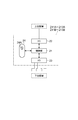
- FIG. 4 is a diagram illustrating a configuration of a relay node.
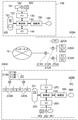
- FIG. 2 is a diagram for explaining a network configuration (one embodiment of a data communication system according to the present invention) that enables bidirectional data communication to which one embodiment of a traffic control device according to the present invention is applied.
- FIG. 2 In the network configuration shown in FIG. 2, a plurality of local networks 200A and 200B are connected to the Internet 10 via representative nodes 211A and 211B.
- the traffic control device 100 according to the present embodiment is also connected to the Internet 10.
- the traffic control device 100 may be any component (for example, a relay node, a PC, etc.) of the local networks 200A and 200B.
- the local network 200A includes a relay node group 210A (including a plurality of relay nodes 211A, 212A, and 213A) and a plurality of PCs 220A arranged in a lower hierarchy of the relay node group 210A.
- the representative node 211A functions as an uppermost relay node for connecting the local network 200A and the Internet 10. Accordingly, the local network 200A is configured such that each PC 220A belonging to the local network 200A can be connected to the Internet 10 only via the representative node 211A.
- the local network 200B is also configured by a relay node group 210B (including a plurality of relay nodes 211B, 212B, and 213B) and a plurality of PCs 220B arranged in a lower hierarchy of the relay node group 210B.
- the representative node 211B functions as an uppermost relay node for connecting the local network 200B and the Internet 10. Therefore, the local network 200B is configured such that each PC 220B belonging to the local network 200B can be connected to the Internet 10 only through the representative node 211B.
- Each of the PCs 220B belonging to the local network 200B includes an input / output unit 270 (hereinafter referred to as I / O) that functions as a communication interface, a control unit 230, a memory 240 as a recording unit, a drawing unit 250, and a monitor 260. And an I / O 280 that functions as an interface for a keyboard 281, a pointing device (mouse) 282, an external recording device 283, and the like.
- the memory 240 is used for bidirectional data communication for enabling bidirectional data communication with other PCs (not limited to the local network 200B but may be a PC belonging to the local network 200A).
- the application 241 and information on usable bandwidth (usable bandwidth information) are stored.
- the control unit 230 functions as a control unit for executing the bidirectional data communication application 241.
- the traffic control device 100 connected to the Internet 10 also includes I / Os 130 and 140 as input / output means, a control unit 110 as control means, a memory 120 as recording means, a drawing unit 150, a monitor. 160.
- the I / O 130 functions as an interface for the keyboard 161, the pointing device 162, the external recording device 163, and the like.
- the I / O 140 functions as an interface for performing data communication between the traffic control device 100 and the Internet 10.
- the memory 120 stores a traffic control application 121 for executing an operation for optimizing communication performance in the traffic control device 100 and a management table 122.
- Each of the above-described relay nodes 211A to 213A and 211B to 213B has a structure as shown in FIG. That is, each relay node controls I / O 22 that functions as a connection interface for the upper layer, I / O 23 that functions as a connection interface for the lower layer, and data exchange control between these I / Os 22 and 23.
- a unit 21 and a memory 24 are provided.
- the memory 24 stores a communication band monitoring application 24 ⁇ / b> A, and the communication band monitoring application 24 ⁇ / b> A is executed by the control unit 21.
- a static management table 122A for grasping the logical network configuration is stored for each local network to be monitored.
- at least the address information of the relay node, the address information of each PC that belongs, and the connection status of each PC are recorded in the static management table 122A.
- Each PC 220A belonging to the local network 200A has the same structure as the above-described PC 220B.
- FIG. 5 is a diagram for explaining the communication performance optimization operation of the local network 200B to be monitored in the network configuration to which the traffic control device 100 according to the present embodiment is applied.
- the area (a) is a diagram for explaining the operation of specifying a relay node that becomes a bottleneck by the traffic control apparatus 100
- the area (b) is the PC 220 ⁇ / b> B by the traffic control apparatus 100.
- FIG. 6 is a diagram for explaining an operation of allocating a use band for data transmission / reception with respect to the data;
- FIG. 5 is a diagram for explaining the communication performance optimization operation of the local network 200B to be monitored in the network configuration to which the traffic control device 100 according to the present embodiment is applied.
- the area (a) is a diagram for explaining the operation of specifying a relay node that becomes a bottleneck by the traffic control apparatus 100
- the area (b) is the PC 220 ⁇ / b> B by the traffic control apparatus 100.
- FIG. 6 is a diagram for explaining an operation of
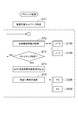
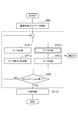
- FIG. 6 is a flowchart for explaining the communication performance optimization operation of the traffic control apparatus according to the present embodiment, and is a flowchart corresponding to the operations shown in the areas (a) and (b) of FIG. is there. Furthermore, FIG. 7 is a flowchart for explaining the data transmission / reception operation in each PC belonging to the local network to be monitored.
- the traffic control device 100 performs communication performance optimization using the local network 200B connected to the Internet 10 via the representative node 211B as a monitoring target.
- the traffic control apparatus 100 executes a traffic control application 121
- the relay nodes 211B to 213B execute a communication band monitoring application 24A.
- each PC 220 ⁇ / b> B is installed with a bidirectional data communication application 241 that enables the PC operation status to be grasped by the traffic control application 121 executed in the traffic control device 100.
- the traffic control device 100 and each PC 220B have the structure shown in FIG.
- the communication band monitoring application 24A may be executed by a device other than the devices constituting the relay node.
- the traffic control device 100 identifies the local network 200B as the monitoring target network (step ST1).
- the traffic control device 100 sequentially acquires communication band information from each of the relay nodes 211B to 213B of the local network 200B as traffic information (step ST2).
- the communication band information of each of the relay nodes 211B to 213B may be acquired via input / output means (I / O) in each relay node, or may be acquired from a server or the like having band management information. Good.
- the traffic information is sequentially stored in the memory 120 in the traffic control device 100, and this acquisition operation is repeated until a relay node that causes a decrease in communication performance of the entire local network 200B, that is, a relay node that becomes a bottleneck is identified. (Step ST3). Specifically, the communication band information of each relay node stored in the memory 120 is compared, and the narrowest-band relay node is identified as a bottleneck.
- the traffic control device 100 determines that the PC 220B that belongs to the local network 200B to be monitored (the PC that is executing the bidirectional data communication application 241; (Referred to as an operating PC), an available bandwidth that can be used for data transmission / reception is allocated. Specifically, as shown in the area (b) of FIG. 5 and FIG. 6, the number of PCs in which the control unit 110 is operating and the communication band of the relay node that is a bottleneck (stored in the memory 120) From the traffic information), a usable bandwidth (transmittable / receivable bandwidth) to be notified to the operating PC is calculated (step ST4).
- the total value of the usable bandwidth notified to each operating PC is set so as not to exceed the communication bandwidth of the relay node that is a bottleneck. Then, the information regarding the usable bandwidth calculated as described above is transmitted to each active PC among the PCs 220B belonging to the local network 200B via the I / O 140 (step ST5).
- step ST6 Bidirectional data communication is performed with the counterpart PC via the I / O 270.
- This bidirectional data communication is performed by the control unit 230 executing the bidirectional data communication application 241 stored in the memory 240.
- digital data voice, image, etc.
- step ST7-1 digital data (voice, image, etc.) from the counterpart PC
- step ST7-2 digital data transmission operation to the counterpart PC are performed in parallel. That is, in the receiving operation on the operating PC side, when digital data is received from the partner PC (step ST7-1), the received data is processed as necessary, such as display on a monitor (step ST7-1). Step ST7-2).
- step ST8-1 digital data to be transmitted to the counterpart PC is generated (step ST8-1), and the sequentially generated data is transmitted to the counterpart PC (step ST8- 2).
- step ST9 Such a transmission / reception operation is continued until the bidirectional data communication (communication) between the operating PC and the partner PC is completed (step ST9), and is established between the operating PC and the partner PC at the end of the communication.
- the connection (line) is disconnected (step ST10).
- the present embodiment is applied to bidirectional data communication.
- the PC in operation only performs a transmission operation and the partner PC performs only a reception operation.
- the present embodiment can be similarly applied even in the case of direction data communication.
- various modifications can be made to the digital data generation operation in step ST8-1.
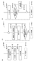
- step ST8-1 in the first operation example of data generation (step ST8-1) performed on the operating PC side, first, usable bandwidth information stored in the memory 240 in advance. (Default value, value at the time of previous operation, value rewritten by interrupt processing described later, etc.) are read out (step ST8111), and the transmittable code amount and data amount are calculated based on the usable bandwidth information. (Step ST8112). Then, compressed data and the like are generated so as to have the code amount and data amount calculated in step ST8112 (step ST8113). The digital data obtained through the above steps ST8111 to ST8113 is transmitted to the partner PC (step ST8-2).
- step ST8-1 the data should be transmitted from the operating PC side to the partner PC.
- a code amount and a data amount are set (step ST8121).
- compressed data etc. are produced
- step ST8123 it is determined whether or not the data amount of the digital data is within the range of usable bandwidth information read from the memory 240 (step ST8123). If it is determined in step ST8123 that the amount of generated digital data or the like is not within the read usable bandwidth information range, steps ST8121 to ST8122 are executed again.
- the data compression rate is increased by reducing the bit rate, the frame rate, etc. during compression, or the data is thinned out. If it is determined that the data amount or the like is within the read usable bandwidth information range, the digital data obtained through steps ST8121 to ST8122 is transmitted to the counterpart PC (step ST8-2). .
- step ST8-1 in the third operation example of data generation (step ST8-1) performed on the operating PC side, transmission is performed according to a preset condition (default value).
- Trusted digital data is generated (step ST8131), and it is determined whether the data amount of the digital data is within the range of usable bandwidth information read from the memory 240 (step ST8132).
- step ST813 when it is determined that the data amount of the generated digital data is not within the read usable band information range, a part of the generated data is cut out (step ST8133).
- the data selection in step ST 8133 is executed, for example, by thinning out frames or by extracting a part of data constituting the JPEG2000 scalability structure.
- the digital data obtained in step ST811 is transmitted to the counterpart PC ( Step ST8-2).
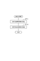
- Interrupt processing is performed. For example, as shown in FIG. 9, this interrupt process is performed by the control unit 230 of the operating PC.
- the control unit 230 converts the received usable bandwidth information into the usable bandwidth information. It is executed by storing it in the memory 240. Note that the usable bandwidth information stored in the memory 240 is rewritten by such an operation of writing the usable bandwidth information into the memory 240.
- the operating PC divides the data to be transmitted (see the flowcharts of FIGS. 7 to 8) generated based on the usable bandwidth information in the memory 240 rewritten by the interrupt process, and is assigned the divided data.
- the data is transmitted to the Internet 10 in a state of being arranged approximately evenly in time so as not to exceed the bandwidth.
- each PC 220B belonging to the local network 200B to be monitored is in communication status of other PCs. It is possible to transmit and receive data within the range of the communication band allocated to itself without being affected. As a result, it is possible to avoid a situation in which the throughput is extremely lowered only for some PCs, and the communication performance of the entire local network 200B is optimized.
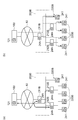
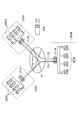
- a plurality of local networks 200A, 200B, and 200C are connected to the Internet 10 through representative nodes 211A, 211B, and 211C.
- the traffic control device 100 according to the present embodiment is also connected to the Internet 10. Note that the traffic control device 100 may be any component of the local networks 200A, 200B, and 200C.
- FIG. 10 only the monitoring target candidate local networks 200A, 200B, and 200C of the traffic control apparatus 100 according to the present embodiment are disclosed, but the Internet 10 is connected to a number of local networks that are not monitored. Yes.
- a communication band monitoring application is installed in advance in the relay node, and the traffic control apparatus 100 can acquire communication band information.
- each of the PCs belonging to the monitoring target candidate local network is a common bidirectional data communication application for enabling transmission and reception of digital data such as voice and images.
- the traffic control apparatus 100 identifies the local network to which these PCs belong as a monitoring target by grasping the PCs constituting the active communication group.
- the local network 200A includes a representative node 211A (a plurality of relay nodes may be arranged in a lower hierarchy of the representative node 211A) and a plurality of PCs 220A arranged in a lower hierarchy of the representative node 211A.
- the representative node 211A functions as an uppermost relay node for connecting the local network 200A and the Internet 10. Accordingly, the local network 200A is configured such that each PC 220A belonging to the local network 200A can be connected to the Internet 10 only via the representative node 211A.
- the local network 200B includes a representative node 211B (a plurality of relay nodes may be arranged in a lower layer of the representative node 211B) and a plurality of PCs 220B arranged in a lower layer of the representative node 211B.
- the representative node 211B functions as an uppermost relay node for connecting the local network 200B and the Internet 10. Therefore, the local network 200B is configured such that each PC 220B belonging to the local network 200B can be connected to the Internet 10 only through the representative node 211B.
- the local network 200C includes a representative node 211C (a plurality of relay nodes may be arranged in a lower hierarchy of the representative node 211C) and a plurality of PCs 220C arranged in a lower hierarchy of the representative node 211C.
- the representative node 211C functions as a top-level relay node for connecting the local network 200C and the Internet 10. Accordingly, the local network 200C is configured such that each PC 220C belonging to the local network 200C can be connected to the Internet 10 only through the representative node 211C.
- the PCs 220A, 220B, and 220C belonging to any of the above-described local networks 200A, 200B, and 200C also have the structure shown in FIG. Further, in each of the PCs 220A, 220B, and 220C, the same bidirectional data communication application 241 is installed in the memory 240 so that the traffic control device 100 can grasp its own operation status. The operating status of each PC means whether or not the interactive data communication application 241 is executed by the control unit 230.
- the traffic control apparatus 100 according to the present embodiment in which the connection to the Internet 10 is established has the structure shown in FIG. 2, and the control means 110 executes the traffic control application 121.
- the traffic control apparatus 100 refers to the static management table 121A stored in the memory 120, and selects the local network to which the active PC participating in each communication belongs as shown in FIG. Managed by the target management table 121B.
- This dynamic management table 121B is also stored in the memory 120 of the traffic control device 100. Then, communication band information is acquired as sequential traffic information from a relay node in the local network to which the operating PC belongs.
- the first communication C1 is performed by four PCs, and each of the local networks 200A, 200B, and 200C to which each PC belongs is related to the first communication C1. It becomes a monitoring target regarding the communication C1.
- another communication is performed by two PCs.
- each of the local networks 200A and 200B to which each PC belongs is monitored with respect to the second communication. Become.
- the traffic control device 100 monitors each of the local networks 200A, 200B, and 200C to which the PCs (operating PCs) constituting the communication grasped as described above belong to each of the relay nodes (representative in the example of FIG. 10).
- Communication band information is acquired from the nodes 211A, 211B, 211C) as traffic information via the I / O 140.
- the acquired communication band information is sequentially stored in the memory 120.
- the traffic control device 100 belongs to the local network including the representative node serving as the bottleneck. It can be used for data transmission / reception with respect to each of the operating PCs (PCs executing the interactive data communication application 241) participating in one of the first and second communications C1 and C2 among the PCs. Allocate available bandwidth. Specifically, similarly to the optimization operation shown in the area (b) of FIG. 5 and FIG.
- the number of PCs in which the control unit 110 is operating and the communication band of the relay node that becomes a bottleneck is calculated from the traffic information stored in (1).
- the total usable bandwidth notified to each operating PC that is, the total communication bandwidth used in each communication is set so as not to exceed the communication bandwidth of the relay node that is the bottleneck.
- the information regarding the usable bandwidth calculated as described above is transmitted to each active PC among the PCs belonging to the local network including the relay node serving as the bottleneck via the I / O 140.
- each operating PC performs digital data transmission / reception according to the flowcharts shown in FIGS. 7 to 8 as described above, and each operating PC that has received notification of the usable bandwidth from the traffic control device 100. Then, the interrupt process shown in FIG. 9 is performed. In other words, the operating PC divides the data to be transmitted generated based on the usable bandwidth information in the memory 240 rewritten by the interrupt processing, and the divided data is timed so as not to exceed the allocated bandwidth. Are sent to the counterpart PC in a substantially evenly arranged state. Note that the information related to the usable bandwidth is also transmitted to the partner PC that communicates with the PC including the relay node identified as the bottleneck.
- each partner PC also performs digital data transmission / reception operations according to the flowcharts shown in FIGS. 7 to 8 as described above, and each partner PC that has received notification of the usable bandwidth from the traffic control device 100. Then, the interrupt process shown in FIG. 9 is performed. In other words, the partner PC divides the data to be transmitted generated based on the usable bandwidth information in the memory 240 rewritten by the interrupt processing, and time so that the divided data does not exceed the allocated bandwidth. To the operating PC in a substantially evenly arranged state
- each PC 220B belonging to the local network 200B to be monitored is in communication status of other PCs. It is possible to transmit and receive data within the range of the communication band allocated to itself without being affected. As a result, it is possible to avoid a situation in which the throughput is extremely lowered only for some PCs, and the communication performance of the entire local network 200B is optimized.
- DESCRIPTION OF SYMBOLS 10 ... Internet (data communication network), 100 ... Traffic control apparatus, 200A, 200B, 200C ... Local network, 211A, 211B, 211C ... Representative node (top relay node), 210A, 210B ... Relay node group, 212A, 213A , 212B, 213B ... lower relay nodes, 22, 23, 130, 140, 270, 280 ... I / O (input / output means), 21, 110, 230 ... control unit (control means), 24, 120, 240 ... memory (Recording means) 121... Traffic control application 122... Management table 122 A. Static management table 122 B Dynamic management table 24 A Communication bandwidth monitoring application 241 Bidirectional data communication application
Landscapes
- Engineering & Computer Science (AREA)
- Signal Processing (AREA)
- Computer Networks & Wireless Communication (AREA)
- Environmental & Geological Engineering (AREA)
- Data Exchanges In Wide-Area Networks (AREA)
- Small-Scale Networks (AREA)
Priority Applications (6)
| Application Number | Priority Date | Filing Date | Title |
|---|---|---|---|
| JP2011523672A JPWO2011010657A1 (ja) | 2009-07-22 | 2010-07-21 | トラフィック制御装置を含むデータ通信システム |
| US13/384,924 US8774002B2 (en) | 2009-07-22 | 2010-07-21 | Traffic control apparatus and data communication system including same |
| IN615DEN2012 IN2012DN00615A (enExample) | 2009-07-22 | 2010-07-21 | |
| CN201080033389.XA CN102474434B (zh) | 2009-07-22 | 2010-07-21 | 通信量控制设备和包括其的数据通信系统 |
| EP10802277.3A EP2458789B1 (en) | 2009-07-22 | 2010-07-21 | Data communication system |
| BR112012001470-6A BR112012001470A2 (pt) | 2009-07-22 | 2010-07-21 | Aparelho de controle de tráfego e sistema de comunicação de dados incluindo o mesmo |
Applications Claiming Priority (2)
| Application Number | Priority Date | Filing Date | Title |
|---|---|---|---|
| JP2009171396 | 2009-07-22 | ||
| JP2009-171396 | 2009-07-22 |
Publications (1)
| Publication Number | Publication Date |
|---|---|
| WO2011010657A1 true WO2011010657A1 (ja) | 2011-01-27 |
Family
ID=43499129
Family Applications (1)
| Application Number | Title | Priority Date | Filing Date |
|---|---|---|---|
| PCT/JP2010/062226 Ceased WO2011010657A1 (ja) | 2009-07-22 | 2010-07-21 | トラフィック制御装置及びそれを含むデータ通信システム |
Country Status (7)
| Country | Link |
|---|---|
| US (1) | US8774002B2 (enExample) |
| EP (1) | EP2458789B1 (enExample) |
| JP (1) | JPWO2011010657A1 (enExample) |
| CN (1) | CN102474434B (enExample) |
| BR (1) | BR112012001470A2 (enExample) |
| IN (1) | IN2012DN00615A (enExample) |
| WO (1) | WO2011010657A1 (enExample) |
Cited By (1)
| Publication number | Priority date | Publication date | Assignee | Title |
|---|---|---|---|---|
| WO2023275091A1 (en) | 2021-06-29 | 2023-01-05 | Química Sintética, S.A. | Processes for the preparation of non-steroidal antiandrogens |
Families Citing this family (2)
| Publication number | Priority date | Publication date | Assignee | Title |
|---|---|---|---|---|
| WO2014175089A1 (ja) * | 2013-04-26 | 2014-10-30 | 株式会社オートネットワーク技術研究所 | フェイルセーフ回路 |
| US10481823B2 (en) | 2018-02-21 | 2019-11-19 | International Business Machines Corporation | Data storage system performing data relocation based on temporal proximity of accesses |
Citations (3)
| Publication number | Priority date | Publication date | Assignee | Title |
|---|---|---|---|---|
| JPH11161571A (ja) | 1997-11-27 | 1999-06-18 | Fujitsu Ltd | 適応的伝送制御システム |
| JP2007251660A (ja) | 2006-03-16 | 2007-09-27 | Nec Corp | 無線通信システム、無線通信端末、無線基地局、同時接続数決定方法、および無線通信システムのプログラム |
| WO2009028185A1 (ja) * | 2007-08-28 | 2009-03-05 | Panasonic Corporation | ネットワーク制御装置、方法、及びプログラム |
Family Cites Families (3)
| Publication number | Priority date | Publication date | Assignee | Title |
|---|---|---|---|---|
| JP4214960B2 (ja) | 2004-06-24 | 2009-01-28 | 株式会社日立製作所 | 無線通信ネットワークシステム |
| GB2422272A (en) * | 2005-01-14 | 2006-07-19 | King S College London | Network mobility |
| WO2008156782A2 (en) * | 2007-06-19 | 2008-12-24 | Sand Holdings, Llc | Devices and methods for automatic reset of monitored network network equipment |
-
2010
- 2010-07-21 BR BR112012001470-6A patent/BR112012001470A2/pt not_active IP Right Cessation
- 2010-07-21 WO PCT/JP2010/062226 patent/WO2011010657A1/ja not_active Ceased
- 2010-07-21 EP EP10802277.3A patent/EP2458789B1/en not_active Not-in-force
- 2010-07-21 IN IN615DEN2012 patent/IN2012DN00615A/en unknown
- 2010-07-21 CN CN201080033389.XA patent/CN102474434B/zh not_active Expired - Fee Related
- 2010-07-21 JP JP2011523672A patent/JPWO2011010657A1/ja active Pending
- 2010-07-21 US US13/384,924 patent/US8774002B2/en not_active Expired - Fee Related
Patent Citations (3)
| Publication number | Priority date | Publication date | Assignee | Title |
|---|---|---|---|---|
| JPH11161571A (ja) | 1997-11-27 | 1999-06-18 | Fujitsu Ltd | 適応的伝送制御システム |
| JP2007251660A (ja) | 2006-03-16 | 2007-09-27 | Nec Corp | 無線通信システム、無線通信端末、無線基地局、同時接続数決定方法、および無線通信システムのプログラム |
| WO2009028185A1 (ja) * | 2007-08-28 | 2009-03-05 | Panasonic Corporation | ネットワーク制御装置、方法、及びプログラム |
Non-Patent Citations (2)
| Title |
|---|
| "Multimedia, Distributed, Cooperative, and Mobile (DICOM02007) Symposium Ronbunshu, IPSJ Symposium Series vol.2007, no.l, [CD-ROM], 04 July 2007 (04.07.2007)", article TERUKI SUKENARI ET AL.: "End-to-End Packet Denso Model ni Motozuku Real-Time-sei o Koryo shita Kayotaiiki Haba Suitei Hoshiki", pages: 939 - 945, XP008149131 * |
| See also references of EP2458789A4 |
Cited By (1)
| Publication number | Priority date | Publication date | Assignee | Title |
|---|---|---|---|---|
| WO2023275091A1 (en) | 2021-06-29 | 2023-01-05 | Química Sintética, S.A. | Processes for the preparation of non-steroidal antiandrogens |
Also Published As
| Publication number | Publication date |
|---|---|
| EP2458789B1 (en) | 2016-08-31 |
| JPWO2011010657A1 (ja) | 2013-01-07 |
| US20120134270A1 (en) | 2012-05-31 |
| EP2458789A1 (en) | 2012-05-30 |
| US8774002B2 (en) | 2014-07-08 |
| EP2458789A4 (en) | 2015-08-19 |
| IN2012DN00615A (enExample) | 2015-06-12 |
| CN102474434A (zh) | 2012-05-23 |
| BR112012001470A2 (pt) | 2021-03-30 |
| CN102474434B (zh) | 2015-04-08 |
Similar Documents
| Publication | Publication Date | Title |
|---|---|---|
| US9479384B2 (en) | Data stream scheduling method, device, and system | |
| EP2925049B1 (en) | Bandwidth management method, evolved node b, serving gateway, and communication system | |
| EP2064906B1 (en) | Method for recovering connectivity in the event of a failure in a radio communications system and controlling node thereof | |
| JP5453928B2 (ja) | ルーティング装置、通信制御方法および通信システム | |
| CA2858895C (en) | Dynamic channel bonding partial service triggering | |
| CN108494788A (zh) | 数据的传输方法、数据传输装置及计算机可读存储介质 | |
| JP2014241493A (ja) | 送信装置、送信方法及びプログラム | |
| US10911364B2 (en) | Packet processing method and router | |
| CN102984784A (zh) | 通过多个网络发送数据 | |
| WO2011010657A1 (ja) | トラフィック制御装置及びそれを含むデータ通信システム | |
| CN106411764B (zh) | 一种带宽配置的动态调整方法和基站设备 | |
| EP2975811A1 (en) | Interface switching method and device | |
| JP2009278297A (ja) | ゲートウエイ装置およびそれを含む通信システムならびに通信方法 | |
| CN102984785A (zh) | 通过多个网络发送数据 | |
| US20070064606A1 (en) | Multiple network system and service providing method | |
| JP4277365B2 (ja) | 動画配信システム | |
| US10504482B2 (en) | Smart small form-factor pluggable (SFP) transceiver | |
| US20220141913A1 (en) | Core network for mobile communication system | |
| US10212640B2 (en) | Identifying communication paths based on packet data network gateway status reports | |
| US9641582B2 (en) | Bandwidth management device, central management device and method of bandwidth management | |
| US9876724B2 (en) | Method for seamless multi-link network connectivity | |
| EP2239916A1 (en) | Improved application of unreliable transfer mechanisms | |
| CN114374683B (zh) | 一种档案文件的管理方法、系统及计算机可读存储介质 | |
| WO2025218372A1 (zh) | 一种业务信号的发送方法及相关设备 | |
| JP2023182982A (ja) | 映像伝送システム、映像伝送装置、及び映像伝送プログラム |
Legal Events
| Date | Code | Title | Description |
|---|---|---|---|
| WWE | Wipo information: entry into national phase |
Ref document number: 201080033389.X Country of ref document: CN |
|
| 121 | Ep: the epo has been informed by wipo that ep was designated in this application |
Ref document number: 10802277 Country of ref document: EP Kind code of ref document: A1 |
|
| WWE | Wipo information: entry into national phase |
Ref document number: 2011523672 Country of ref document: JP |
|
| REEP | Request for entry into the european phase |
Ref document number: 2010802277 Country of ref document: EP |
|
| WWE | Wipo information: entry into national phase |
Ref document number: 2010802277 Country of ref document: EP |
|
| WWE | Wipo information: entry into national phase |
Ref document number: 615/DELNP/2012 Country of ref document: IN |
|
| NENP | Non-entry into the national phase |
Ref country code: DE |
|
| WWE | Wipo information: entry into national phase |
Ref document number: 13384924 Country of ref document: US |
|
| REG | Reference to national code |
Ref country code: BR Ref legal event code: B01A Ref document number: 112012001470 Country of ref document: BR |
|
| ENP | Entry into the national phase |
Ref document number: 112012001470 Country of ref document: BR Kind code of ref document: A2 Effective date: 20120123 |