WO2011007681A1 - Glass plate production method and production device - Google Patents
Glass plate production method and production device Download PDFInfo
- Publication number
- WO2011007681A1 WO2011007681A1 PCT/JP2010/061279 JP2010061279W WO2011007681A1 WO 2011007681 A1 WO2011007681 A1 WO 2011007681A1 JP 2010061279 W JP2010061279 W JP 2010061279W WO 2011007681 A1 WO2011007681 A1 WO 2011007681A1
- Authority
- WO
- WIPO (PCT)
- Prior art keywords
- guide member
- glass
- molten glass
- glass plate
- molded body
- Prior art date
Links
Images


Classifications
-
- C—CHEMISTRY; METALLURGY
- C03—GLASS; MINERAL OR SLAG WOOL
- C03B—MANUFACTURE, SHAPING, OR SUPPLEMENTARY PROCESSES
- C03B17/00—Forming molten glass by flowing-out, pushing-out, extruding or drawing downwardly or laterally from forming slits or by overflowing over lips
- C03B17/06—Forming glass sheets
- C03B17/064—Forming glass sheets by the overflow downdraw fusion process; Isopipes therefor
-
- C—CHEMISTRY; METALLURGY
- C03—GLASS; MINERAL OR SLAG WOOL
- C03B—MANUFACTURE, SHAPING, OR SUPPLEMENTARY PROCESSES
- C03B17/00—Forming molten glass by flowing-out, pushing-out, extruding or drawing downwardly or laterally from forming slits or by overflowing over lips
- C03B17/04—Forming tubes or rods by drawing from stationary or rotating tools or from forming nozzles
-
- C—CHEMISTRY; METALLURGY
- C03—GLASS; MINERAL OR SLAG WOOL
- C03B—MANUFACTURE, SHAPING, OR SUPPLEMENTARY PROCESSES
- C03B18/00—Shaping glass in contact with the surface of a liquid
- C03B18/02—Forming sheets
Definitions
- the present invention relates to a glass plate manufacturing method and manufacturing apparatus.
- a method called a fusion method has been known as a method for producing a high-quality glass plate (for example, see Patent Document 1).
- molten glass is allowed to flow down along both side surfaces of a wedge-shaped molded body that converges downward, and these molten glasses are merged and integrated directly below the lower edge of the molded body.
- the plate-shaped glass ribbon is stretched downward while being cooled.
- Patent Document 1 in order to prevent the molten glass flowing down from shrinking in the width direction due to surface tension, a web-like member is provided in the vicinity of the left and right ends of both side surfaces of the molded body, and the web-like member intersects with the web-like member.
- the provision of an extension member inclined downward with respect to the shaped member is described.
- the width direction edge part of a molten glass flows along the surface of a web-like member, and then flows along the surface of an extension member.
- Patent Document 2 in order to prevent the molten glass flowing down from shrinking in the width direction due to surface tension, the front and back surfaces of the molded body are integrally connected at the lower edges of both sides (front and back surfaces) of the molded body.
- a triangular fin-like projecting body having two sides in contact with and fixed to the inner wall of the lower end portion of the guide wall and the lower edge of the molded body is described.
- This invention was made in view of the said subject, Comprising: It aims at providing the manufacturing method and manufacturing apparatus of a glass plate with easy adjustment of the shape dimension of a glass ribbon.
- the present invention provides: The molten glass is allowed to flow along both side surfaces of the molded body, the molten glass is merged and integrated just below the lower edge of the molded body, and the integrated plate-like glass ribbon is drawn downward to be molded.
- the manufacturing method of the glass plate containing Provide a guide member that contacts the width direction end of the molten glass that has joined, The relative position and / or angle between the guide member and the lower edge of the molded body is adjusted.
- the present invention also provides: A glass plate that has a molded body that merges and integrates molten glass that has flowed down along both side surfaces directly below the lower edge, and that is formed by stretching a plate-like glass ribbon integrated by the molded body downward.
- a glass plate that has a molded body that merges and integrates molten glass that has flowed down along both side surfaces directly below the lower edge, and that is formed by stretching a plate-like glass ribbon integrated by the molded body downward.
- An end portion in the width direction of the joined molten glass is in contact, and has a guide member that is supported so that the position and / or angle with respect to the lower edge of the molded body can be adjusted.
- the present invention it is possible to provide a glass plate manufacturing method and manufacturing apparatus in which the shape and size of the glass ribbon can be easily adjusted.
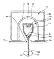
- FIG. 1 is a cross-sectional view showing a glass plate manufacturing apparatus according to an embodiment of the present invention.
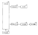
- FIG. 2 is a functional block diagram showing a control system of the glass plate manufacturing apparatus of FIG.
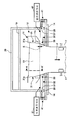
- FIG. 3 is a side view showing a part of the glass plate manufacturing apparatus of FIG. 4 is a cross-sectional view taken along the line AA ′ of FIG.
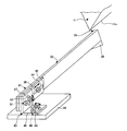
- FIG. 5 is a perspective view showing a positional relationship between the distal end portion 33 of the guide member 32 and the molten glass 15.
- FIG. 6 is a perspective view for explaining the configuration and operation of the support mechanism 41.
- FIG. 7 is a perspective view showing a modification of FIG.
- FIG. 8 is a perspective view showing another modification of FIG.
- FIG. 9 is a perspective view showing a modification of FIG. FIG.
- FIG. 10 is a perspective view showing another modification of FIG.
- FIG. 11A is a top view showing the distal end portion 33B of the guide member 32B of FIG. 10 and its peripheral portion.
- 11B is a partial cross-sectional side view showing the distal end portion 33B of the guide member 32B of FIG. 10 and its peripheral portion.
- FIG. 11C is a front view showing the distal end portion 33B of the guide member 32B of FIG. 10 and its peripheral portion.
- FIG. 11D is a perspective view showing the distal end portion 33B of the guide member 32B of FIG. 10 and its peripheral portion.
- FIG. 12 is a perspective view showing still another modified example of FIG.
- FIG. 13A is a top view showing the distal end portion 33B of the guide member 32B of FIG. 12 and its peripheral portion.
- FIG. 13B is a partial cross-sectional side view showing the distal end portion 33B of the guide member 32B of FIG. 12 and its peripheral portion.
- FIG. 13C is a front view showing the distal end portion 33B of the guide member 32B of FIG. 12 and its peripheral portion.
- 13D is a perspective view showing the distal end portion 33B of the guide member 32B of FIG. 12 and its peripheral portion.
- FIG. 1 is a cross-sectional view showing a glass plate manufacturing apparatus according to an embodiment of the present invention.
- FIG. 2 is a functional block diagram showing a control system of the glass plate manufacturing apparatus of FIG.
- the glass plate manufacturing apparatus includes a molded body 11 that merges and integrates molten glass that has flowed down along both side surfaces immediately below the lower edge portion, a molding chamber 12 in which the molded body 11 is disposed, and a molded body 11.
- a molding chamber opening 13 for drawing the integrated plate-shaped glass ribbon downward from the molding chamber 12 is provided.
- the molding chamber opening 13 is formed by the opening member 14.
- the molded body 11 is made of a refractory such as alumina or zirconia.
- the molded body 11 has a wedge-shaped cross section that converges downward.
- a concave portion 16 for accommodating the molten glass 15 is formed on the upper portion of the molded body 11.
- a molten glass supply pipe (not shown) is connected to the recess 16. The molten glass 15 supplied from the molten glass supply pipe into the recess 16 overflows from the upper edge of the recess 16 (that is, the upper edge of the molded body 11) 11a, flows down along both side surfaces of the molded body 11, and is molded. The body 11 merges just below the lower edge 11b.
- the angle ⁇ formed by both side surfaces of the lower edge portion 11b of the molded body 11 is preferably 15 ° to 36 °.
- the angle ⁇ is larger than 36 °, the joining of the molten glass that has flowed down along both side surfaces becomes unstable.
- the angle ⁇ is larger than 36 °.
- the merging of the molten glass 15 is violently disturbed and molding becomes difficult.
- the angle ⁇ is larger than 36 °, the cross section of the molded body 11 is reduced, and the strength of the molded body 11 is reduced, so that the molded body 11 may be creep-deformed.
- the angle ⁇ is smaller than 15 °, the lower edge portion 11b may be damaged by thermal stress when the molded body 11 is heated when the glass plate manufacturing apparatus is started up.
- the merged molten glass 15 becomes a plate-like glass ribbon 15A.
- the glass ribbon 15 ⁇ / b> A is formed by being drawn downward by a pair of rollers 17 that are rotationally driven by a driving device 71.
- a pair of rollers 17 is installed on each of the left and right sides of the glass ribbon 15A, and each of the rollers 17 holds the end of the glass ribbon 15A in the width direction and pulls it downward.
- a plurality of pairs of rollers 17 may be further installed in the vertical direction.
- the formed glass ribbon 15A is cut off at both ends in the width direction, and the remaining center portion in the width direction is used as a product glass plate.
- the molding chamber 12 is installed inside the furnace chamber 18.
- the molding chamber 12 and the furnace chamber 18 are partitioned by a partition wall 19.
- the partition wall 19 is placed and fixed on the floor surface of the furnace wall 20 that forms the furnace chamber 18.
- the partition wall 19 and the furnace wall 20 are made of a refractory material.
- FIG. 3 is a side view of the glass plate manufacturing apparatus of FIG.
- the arrow F direction indicates the flow direction of the glass ribbon 15A.
- 4 is a cross-sectional view taken along the line AA ′ of FIG.
- the glass plate manufacturing apparatus includes a guide wall 31, a guide member 32, a support mechanism 41, and a temperature adjusting member 61 as shown in FIG.
- the guide wall 31 is formed of a refractory material such as alumina, zirconia, or zircon.
- the guide walls 31 extend from the upper edge 11a toward the lower edge 11c in the vicinity of the left and right ends of both side surfaces of the molded body 11, respectively.
- the molten glass 15 flowing down along the side surface of the molded body 11 spreads to the left and right guide walls 31 and flows down while contacting the inner wall surfaces 31a of the left and right guide walls 31, and then separates from the left and right guide walls 31. Flow down.
- the flow width is narrowed by the surface tension.
- the molten glass 15 flowing down comes into contact with the guide wall 31 and gets wet, so that the width of the flow can be prevented from being reduced.
- the position of the lower edge 31b of the guide wall 31 is appropriately set according to the shape and size of the molded body 11, the flow rate and viscosity of the molten glass 15, and the like.
- a distance L in the vertical direction from the lower edge 31b of the guide wall 31 to the predetermined portion 39 on the side surface of the molded body 11 (however, the distance L is lower than the predetermined portion 39 on the side surface of the molded body 11 at the lower edge 31b of the guide wall 31).
- the case where it is on the lower side is positive, and the case where the lower edge 31b of the guide wall 31 is on the upper side of the predetermined portion 39 on the side surface of the molded body 11 is negative)) is preferably ⁇ 200 mm to 200 mm, More preferably, it is ⁇ 10 mm to 5 mm.
- the predetermined portion 39 on the side surface of the molded body 11 means the upper edge of a region of the side surface of the molded body 11 where the molten glass 15 is in contact from below. If the distance L is greater than 200 mm, the diversion 15B is likely to occur. If the distance L is smaller than -200 mm, the contraction width of the flow due to the surface tension is too large.
- the guide member 32 is made of a material having good heat resistance and corrosion resistance, for example, ceramics or heat resistant alloy.
- ceramics for example, alumina, zirconia, zircon, silicon nitride, silicon carbide, boron nitride, refractories such as alumina and zirconia can be used.
- heat-resistant alloy for example, iron-chromium alloy, nickel alloy, cobalt alloy and the like can be used.
- the guide members 32 are installed one by one on both the left and right sides of the molten glass 15 that have joined just below the lower edge portion 11b of the molded body 11.
- the joined molten glass 15 spreads to the tip portions 33 of the left and right guide members 32 and flows down in contact with the tip portions 33.
- the width of the flow is reduced by the surface tension.
- the joined molten glass 15 comes into contact with the distal end portion 33 of the guide member 32 and gets wet, so that it is possible to prevent the flow width from being narrowed.
- the distance S in the vertical direction between the distal end portion 33 of the guide member 32 and the lower edge 11c of the molded body 11 is preferably 30 mm or less.
- the distance S is larger than 30 mm, the molten glass 15 is separated from the lower edge portion 11b of the molded body 11, and at the same time, the flow width is greatly contracted.
- tip part 33 of the guide member 32 and the lower edge part 11b of the molded object 11 may contact as long as the relative position and / or angle can be changed.
- FIG. 5 is a perspective view showing the positional relationship between the tip 33 of the guide member 32 and the molten glass 15 that has joined.
- the guide member 32 is formed in a long flat plate shape.
- the end portions in the width direction of the molten glass 15 that has joined the both side surfaces 33a of the distal end portion 33 of the guide member 32 flow down while contacting. For this reason, when the flow of the molten glass 15 is disturbed and the width thereof is narrowed, the molten glass 15 is unlikely to come off from the distal end portion 33 of the guide member 32.
- a tapered protrusion 34 protruding downward is integrally formed at the tip 33 of the guide member 32.
- the width direction end of the molten glass 15 that has joined moves toward the lower end 34a of the triangular plate-like projection 34 as it flows down, and moves away from the projection 34 near the lower end 34a of the projection 34.
- the molten glass 15 that contacts the guide member 32 may slide in the longitudinal direction of the guide member 32 when moving away from the guide member 32. For this reason, the flow of the molten glass 15 tends to become unstable.
- the projection part 34 assumed the triangular plate shape, a triangular pyramid shape may be sufficient.
- the protrusion 34 may have a tapered shape that protrudes downward.
- the surface of the distal end portion 33 of the guide member 32 has a first region 35 where the molten glass 15 comes into contact and gets wet, and a second region 36 where the molten glass 15 is harder to get wet than the first region 35. May be.
- the first area 35 is set on the tip side of the second area 36. Thereby, it can suppress that the molten glass 15 which contacts the guide member 32 slips and moves in the longitudinal direction of the guide member 32, and can stabilize the flow of the molten glass 15.
- a method of forming the first and second regions 35 and 36 having different wettability there is a method of forming a thin film having lower wettability than the guide member 32 on a part of the surface of the distal end portion 33 of the guide member 32.
- a boron nitride slurry having a lower wettability than alumina is applied to a part of the surface of the tip 33 of the alumina guide member 32 and dried to form a thin film having a low wettability.
- Other methods include a method of forming a thin film having higher wettability than the guide member 32 on a part of the surface of the distal end portion 33 of the guide member 32, a method of connecting two members having different wettability, and a guide member using plasma. There is a method of surface-treating a part of 32.
- high wettability materials include platinum, platinum group alloys, reinforced platinum or reinforced platinum alloys, and low wettability materials include nitride ceramics, silicon nitride-boron nitride composites, gold or gold-containing alloys. And carbon-based materials such as carbon and graphite, and nitride-carbide composite materials.
- the guide member 32 is inserted into the molding chamber 12 through the opening 28 of the furnace wall 20 and can be replaced without disassembling the partition wall 19 and the furnace wall 20.
- disassembling the partition wall 19 and the furnace wall 20 it is necessary to stop the production of the glass plate for a long time.
- the guide member 32 is supported by the support mechanism 41 so that the position and / or angle with respect to the lower edge 11c of the molded body 11 can be adjusted.
- the support mechanism 41 is a mechanism that supports the guide member 32 so that the position and / or angle with respect to the lower edge 11c of the molded body 11 can be adjusted.
- the support mechanism 41 is provided in the vicinity of the opening 28 of the furnace wall 20.
- the support mechanism 41 includes a first support member 42 that slidably supports the base end portion 37 of the guide member 32 in the longitudinal direction of the guide member 32, and the first support member 42 that is perpendicular to the furnace wall 20. And a second support member 43 that is pivotally supported in the horizontal direction.
- the material of the first support member 42 is not particularly limited, but is formed of a metal material such as stainless steel.
- a linear guide hole 44 is formed in the first support member 42. The threaded portion 38 of the guide member 32 is inserted into the guide hole 44.
- a first support member 42 is fixed to the screw portion 38 with a nut.
- the material of the second support member 43 is not particularly limited, but is formed of a metal material such as stainless steel.
- the second support member 43 is formed in an L shape and has a configuration in which a horizontal plate portion 46 and a vertical plate portion 47 are integrally formed.
- the horizontal plate portion 46 is formed with a shaft support hole 48 and an arcuate cam hole 49 centered on the shaft support hole 48. Screw portions fixed to the furnace wall 20 are inserted through the shaft support holes 48 and the cam holes 49, respectively. A horizontal plate portion 46 is nut-fastened to these screw portions.
- the vertical plate portion 47 is formed with a shaft support hole 51 and an arcuate cam hole 52 centered on the shaft support hole 51. A threaded portion projecting from the first support member 42 is inserted into the shaft support hole 51 and the cam hole 52. The vertical plate portion 47 is nut-fastened to these screw portions.
- each nut is manually loosened, and the first support member 42 is rotated with respect to the furnace wall 20 in the horizontal direction and the vertical direction to adjust the angle. Further, the guide member 32 is slid with respect to the first support member 42 to adjust the position. Thereby, the relative position and / or angle of the guide member 32 and the lower edge 11c of the molded body 11 can be adjusted. After adjustment, each nut is tightened to fix the position and / or angle.
- the relative position and / or angle between the guide member 32 and the lower edge 11c of the molded body 11 is manually adjusted.
- the present invention is not limited to this. That is, the relative position and / or angle between the guide member 32 and the lower edge 11c of the molded body 11 is automatically driven by driving the support mechanism 41 with an actuator 76 (see FIG. 2) such as a hydraulic cylinder, an air cylinder, or a motor. May be adjusted.
- the relative position and / or angle between the guide member 32 and the lower edge 11c of the molded body 11 is adjusted so that the molded glass ribbon 15A has a desired shape and dimension.
- the adjustment of the left and right guide members 32, 32 may be performed symmetrically or asymmetrically.
- the relative position and / or angle of the guide member 32 and the lower edge 11c of the molded body 11 is adjusted based on the average thickness of the glass plate taken out from the center in the width direction of the glass ribbon 15A after molding. Do.
- the thinner the average thickness of the glass plate the thinner the merged molten glass 15 needs to be stretched, and the greater the stress applied to the merged molten glass 15. Therefore, the tip portions 33 of the left and right guide members 32 are moved inward so that the end portions in the width direction of the molten glass 15 joined together can be surely supported as the average thickness of the glass plate is reduced.
- the guide member 32 that has been in contact with the end portion in the width direction is rotated in the horizontal direction to adjust the angle.
- the position of the edge part of the width direction of the molten glass 15 which merged can be adjusted, and generation
- the glass plate to be manufactured can be obtained in a desired manner. It can be a shape dimension.
- the shape dimension of the glass plate manufactured after the adjustment is measured by a measuring device 77 (see FIG. 2).
- the measuring device 77 may be connected to the control device 73.
- the control device 73 drives the support mechanism 41 by the actuator 76 so that the glass plate to be manufactured will have a desired shape and size, and the lower edge 11 c of the molded body 11. The position and / or angle of the guide member 32 with respect to is adjusted.
- the appropriate position and / or angle of the guide member 32 with respect to the lower edge 11c of the molded body 11 tends to vary depending on the molding conditions. This tendency becomes more conspicuous as the average thickness of the glass plate becomes thinner, and particularly, when the average thickness of the glass plate is 0.3 mm or less, the rigidity of the glass plate becomes lower.
- the molding conditions refer to conditions for molding a glass plate.
- the state of the components (molded body 11, partition wall 19, heating element, etc.) constituting the glass plate manufacturing apparatus is included.
- the present embodiment by adjusting the relative position and / or angle between the guide member 32 and the lower edge 11c of the molded body 11, it is possible to easily cope with a change in molding conditions.
- the glass plate of the dimension shape can be obtained. This effect is remarkable when the average thickness of the glass plate is 0.3 mm or less. Moreover, this effect is remarkable when the guide wall 31 is not extended to the lower edge 11c of the molded body 11.
- the temperature adjusting member 61 is a member that adjusts the temperature of the guide member 32. By adjusting the temperature of the guide member 32, it is possible to adjust the temperature distribution and viscosity distribution (and hence the shape dimension) of the molten glass 15 that contacts the guide member 32.
- the members for heating the guide member 32 include an internal heater embedded in the distal end portion 33 of the guide member 32 and an external heater for heating the proximal end portion 37 of the guide member 32 from the outside.
- an internal heater the front-end
- an external heater replacement and repair are easy.
- the material of the guide member 32 is preferably a material having a high thermal conductivity.
- the guide member 32 As a member that cools the guide member 32, there are a refrigerant supply device that causes a refrigerant to flow inside the guide member 32, and a refrigerant supply device that blows the refrigerant from the outside to the base end portion 37 of the guide member 32.
- a refrigerant supply device that causes a refrigerant to flow inside the guide member 32
- a refrigerant supply device that blows the refrigerant from the outside to the base end portion 37 of the guide member 32.
- tip part 33 of the guide member 32 can be cooled efficiently.
- the material of the guide member 32 is preferably a material having a high thermal conductivity.
- the position and / or angle of the guide member 32 with respect to the lower edge 11c of the molded body 11 is adjusted, so that the shape of the glass ribbon 15A can be easily adjusted. Thereby, it can respond easily to the change of molding conditions, and a glass plate of a desired shape dimension can be obtained.
- FIG. 7 is a perspective view showing a modification of FIG.
- the distal end portion 33A of the guide member 32A is formed in a wedge shape in cross section that converges toward the distal end.
- the widthwise end portions of the molten glass 15 that have joined together flow down while being in contact with both side surfaces 33Aa of the tip portion 33A of the guide member 32A. For this reason, similarly to the case of FIG. 5, when the flow of the molten glass 15 is disturbed and its width is narrowed, the molten glass 15 is unlikely to come off from the distal end portion 33 ⁇ / b> A of the guide member 32 ⁇ / b> A.
- a tapered projection 34 ⁇ / b> A that protrudes downward is integrally formed at the tip 33 ⁇ / b> A of the guide member 32 ⁇ / b> A.
- the widthwise end of the molten glass 15 that has joined moves toward the lower end 34Aa of the triangular pyramid-shaped projection 34A as it flows down, and moves away from the projection 34A in the vicinity of the lower end 34Aa of the projection 34A. For this reason, like the case shown in FIG. 5, the flow of the molten glass 15 is easily stabilized.
- the surface of the tip portion 33A of the guide member 32A has a first region 35A where the molten glass 15 comes into contact and gets wet, and a second region 36A where the molten glass 15 is harder to get wet than the first region 35A. You may have.
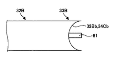
- FIG. 8 is a perspective view showing another modification of FIG.
- the end surface in the width direction of the molten glass 15 that has joined flows down while contacting the tip surface 33Bb of the tip portion 33B of the guide member 32B. For this reason, it can suppress that the flow of the molten glass 15 is disturb
- the cross-sectional shape when the front end surface 33Bb of the guide member 32B is viewed from the flow direction F of the glass ribbon 15A is a concave curved surface having an arc shape.
- the distal end surface 33Bb of the guide member 32B is a concave curved surface having a circular arc shape in a cross section perpendicular to the vertical direction.
- the front end surface 33Bb of the guide member 32B may be a flat surface. Also in this case, the molten glass 15 is relatively difficult to come off from the tip end face 33Bb.
- the front end surface 33Bb of the guide member 32B is a convex curved surface having an arc shape when viewed from the flow direction F of the glass ribbon 15A, when the flow of the molten glass 15 is disturbed and its width is narrowed, The glass 15 is easily slipped off from the front end surface 33Bb.
- FIG. 9 is a perspective view showing a modification of FIG.
- the convex portion 81 is integrally formed on the distal end surface 33 ⁇ / b> Bb of the guide member 32 ⁇ / b> B shown in FIG. 8, and the end portion in the width direction of the molten glass 15 joined to the both side surfaces 81 a of the convex portion 81 Flow down while in contact. For this reason, similarly to the case shown in FIG. 5, when the flow of the molten glass 15 is disturbed and its width is narrowed, the molten glass 15 is unlikely to come off from the convex portion 81.
- the projecting portion 81 is integrally formed with a tapered projecting portion 34B that projects downward.
- the widthwise end of the molten glass 15 that has joined moves toward the lower end 34Ba of the triangular plate-like projection 34B as it flows down, and moves away from the projection 34B in the vicinity of the lower end 34Ba of the projection 34B. For this reason, the flow of the molten glass 15 is easily stabilized.
- the protrusion 34B has a triangular plate shape, but may have a triangular pyramid shape. In short, the protrusion 34B may have a tapered shape that protrudes downward.
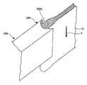
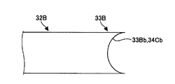
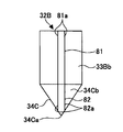
- FIG. 10 is a perspective view showing another modification of FIG. 11A to 11D are views showing the distal end portion 33B and the peripheral portion of the guide member 32B of FIG. 10,
- FIG. 11A is a top view
- FIG. 11B is a partially sectional side view
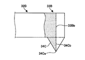
- FIG. 11C is a front view
- a tapered projection 34C protruding downward is integrally formed at the tip 33B of the guide member 32B shown in FIG.
- the protrusion 34C has a side surface 34Cb having a shape (a concave curved surface having an arc shape in cross section) obtained by extending the shape of the tip surface 33Bb in the longitudinal direction of the tip surface 33Bb.
- the end surface in the width direction of the molten glass 15 flows down while contacting the side surface 34Cb.
- the width direction end of the molten glass 15 that has joined moves toward the lower end 34Ca of the projection 34C as it flows down, and moves away from the projection 34C in the vicinity of the lower end 34Ca of the projection 34C. For this reason, the flow of the molten glass 15 is easily stabilized.
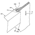
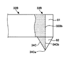
- FIG. 12 is a perspective view showing still another modified example of FIG. 13A to 13D are views showing the distal end portion 33B of the guide member 32B of FIG. 12 and its peripheral portion.
- FIG. 13A is a top view
- FIG. 13B is a partial sectional side view
- FIG. 13C is a front view
- FIG. FIG. 12 is a perspective view showing still another modified example of FIG. 13A to 13D are views showing the distal end portion 33B of the guide member 32B of FIG. 12 and its peripheral portion.
- FIG. 13A is a top view
- FIG. 13B is a partial sectional side view
- FIG. 13C is a front view
- a protrusion 82 is integrally formed with the tip part 33B of the guide member 32B shown in FIG. 8 in addition to the protrusion 81 of FIG. 9 and the protrusion 34C of FIG.
- the protrusion 82 has a triangular shape in side view, and two sides are fixed in contact with the lower surface of the protrusion 81 and the side surface 34Cb of the protrusion 34C.
- the protrusion 82 may have a triangular plate shape as shown in FIG. 13D or a triangular pyramid shape.
- the protrusion 82 may be a tapered shape that protrudes downward.
- the width direction end of the molten glass 15 flows down on both side surfaces 82a of the projection 82. For this reason, when the flow of the molten glass 15 is disturbed and the width thereof is narrowed, the molten glass 15 is unlikely to come off from the protrusions 82. Moreover, the width direction edge part of the molten glass 15 moves toward the lower end 34Ca of the projection part 34C as it flows down, and moves away from the projection part 34C and the projection part 82 in the vicinity of the lower end 34Ca of the projection part 34C. For this reason, the flow of the molten glass 15 is easily stabilized.
- the guide wall 31 extends partway from the upper edge 11a to the lower edge 11c of the molded body 11, but if the distance L is within the above range, or the molded body. 11 and the shape of the guide wall 31 may extend to the lower edge 11c.
- the guide members 32, 32A, and 32B are integrally formed in the longitudinal direction.
- the relative position and / or angle with the lower edge 11c of the molded body 11 is adjusted.
- it may be divided into a plurality of members in the longitudinal direction.
- the base end portions 37 of the guide members 32, 32A, and 32B are supported by the support mechanism 41.
- the present invention is not limited to this.
- the center part in the longitudinal direction of the guide members 32, 32 ⁇ / b> A, and 32 ⁇ / b> B may be supported by the support mechanism 41.
- the support mechanism 41 is configured by the first support member 42 and the second support member 43, but may be configured by only one of them.
- the first support member 42 is fixed to the furnace wall 20.
- the support mechanism 41 is composed of only the second support member 43, the vertical plate portion 47 of the second support member 42 is directly guided by the guide members 32, 32 ⁇ / b> A, 32 ⁇ / b> B without using the first support member 42. Is supported so as to be rotatable in the vertical direction.
- the first support member 42 supports the base end portion 37 of the guide members 32, 32A, 32B so as to be slidable in the longitudinal direction of the guide members 32, 32A, 32B.
- the guide members 32, 32A, and 32B may be slidably supported in a direction orthogonal to the longitudinal direction.
- the present invention it is possible to provide a glass plate manufacturing method and manufacturing apparatus in which the shape and size of the glass ribbon can be easily adjusted.
Abstract
Description
成形体の両側面に沿って溶融ガラスを流下させること、前記成形体の下縁部直下で合流させて一体化させること、および当該一体化した板状のガラスリボンを下方に引き延ばして成形することを含むガラス板の製造方法において、
前記合流した溶融ガラスの幅方向端部が接触するガイド部材を設け、
該ガイド部材と前記成形体の下縁との相対的な位置及び/又は角度を調節する。 In order to solve the above object, the present invention provides:
The molten glass is allowed to flow along both side surfaces of the molded body, the molten glass is merged and integrated just below the lower edge of the molded body, and the integrated plate-like glass ribbon is drawn downward to be molded. In the manufacturing method of the glass plate containing,
Provide a guide member that contacts the width direction end of the molten glass that has joined,
The relative position and / or angle between the guide member and the lower edge of the molded body is adjusted.
下縁部直下で両側面に沿って流下させた溶融ガラスを合流させて一体化させる成形体を有し、前記成形体により一体化した板状のガラスリボンを下方に引き延ばして成形するガラス板の製造装置において、
前記合流した溶融ガラスの幅方向端部が接触し、前記成形体の下縁に対する位置及び/又は角度を調節可能に支持されたガイド部材を有する。 The present invention also provides:
A glass plate that has a molded body that merges and integrates molten glass that has flowed down along both side surfaces directly below the lower edge, and that is formed by stretching a plate-like glass ribbon integrated by the molded body downward. In manufacturing equipment,
An end portion in the width direction of the joined molten glass is in contact, and has a guide member that is supported so that the position and / or angle with respect to the lower edge of the molded body can be adjusted.
図4は、図3のA-A′線に沿った断面図である。 FIG. 3 is a side view of the glass plate manufacturing apparatus of FIG. In FIG. 3, the arrow F direction indicates the flow direction of the
4 is a cross-sectional view taken along the line AA ′ of FIG.
本出願は、2009年7月13日出願の日本特許出願2009-164347に基づくものであり、その内容はここに参照として取り込まれる。 Although the invention has been described in detail and with reference to specific embodiments, it will be apparent to those skilled in the art that various changes and modifications can be made without departing from the spirit and scope of the invention.
This application is based on Japanese Patent Application No. 2009-164347 filed on Jul. 13, 2009, the contents of which are incorporated herein by reference.
11a 上縁
11b 下縁部
11c 下縁
15 溶融ガラス
15A ガラスリボン
32 ガイド部材
33 先端部
33a 側面
33Bb 先端面
34 突起部
61 温度調節部材
81 凸部 DESCRIPTION OF
Claims (20)
- 成形体の両側面に沿って溶融ガラスを流下させること、
前記成形体の下縁部直下で合流させて一体化させること、および
当該一体化した板状のガラスリボンを下方に引き延ばして成形すること、
を含むガラス板の製造方法において、
前記合流した溶融ガラスの幅方向端部が接触するガイド部材を設け、
該ガイド部材と前記成形体の下縁との相対的な位置及び/又は角度を調節する、
ガラス板の製造方法。 Flowing molten glass along both sides of the molded body,
Merging and integrating directly below the lower edge of the molded body, and stretching the integrated plate-like glass ribbon downward to form,
In the manufacturing method of the glass plate containing,
Provide a guide member that contacts the width direction end of the molten glass that has joined,
Adjusting the relative position and / or angle between the guide member and the lower edge of the molded body;
Manufacturing method of glass plate. - 前記合流した溶融ガラスの幅方向端部が、前記ガイド部材の先端部の両側面に接触しながら流下する請求項1記載のガラス板の製造方法。 The manufacturing method of the glass plate of Claim 1 which flows down, the edge part of the width direction of the said molten glass joined together contacting the both sides | surfaces of the front-end | tip part of the said guide member.
- 前記ガイド部材の先端部の表面は、前記合流した溶融ガラスが接触して濡れる第1領域と、前記第1領域よりも前記合流した溶融ガラスが濡れ難い第2領域とを有する請求項1又は2記載のガラス板の製造方法。 The surface of the front-end | tip part of the said guide member has the 1st area | region where the said molten glass which contacted gets wet, and the 2nd area | region where the said molten glass which joined the said area | region is hard to get wet rather than the said 1st area | region. The manufacturing method of the glass plate of description.
- 前記合流した溶融ガラスの幅方向端面が、前記ガイド部材の先端部の先端面に接触しながら流下する請求項1記載のガラス板の製造方法。 The method for producing a glass plate according to claim 1, wherein an end surface of the joined molten glass in the width direction flows down while being in contact with a tip surface of a tip portion of the guide member.
- 前記ガイド部材の先端面を前記ガラスリボンの流れ方向から見たときの断面形状が円弧状の凹曲面又は平面である請求項4記載のガラス板の製造方法。 The method for producing a glass sheet according to claim 4, wherein a cross-sectional shape of the guide member when viewed from a tip direction of the glass ribbon is an arcuate concave curved surface or a flat surface.
- 前記ガイド部材の先端面には、凸部が設けられ、
前記合流した溶融ガラスの幅方向端部が、前記凸部の両側面に接触しながら流下する請求項4又は5記載のガラス板の製造方法。 A convex portion is provided on the distal end surface of the guide member,
The manufacturing method of the glass plate of Claim 4 or 5 which flows down, the edge part of the width direction of the said molten glass joined while contacting the both sides | surfaces of the said convex part. - 前記ガイド部材の先端部には、下方に向けて突出する先細り状の突起部が形成される請求項1~6いずれか一項記載のガラス板の製造方法。 The method for producing a glass plate according to any one of claims 1 to 6, wherein a tapered protrusion projecting downward is formed at a tip of the guide member.
- 前記ガイド部材の温度を調節する請求項1~7いずれか一項記載のガラス板の製造方法。 The method for producing a glass plate according to any one of claims 1 to 7, wherein the temperature of the guide member is adjusted.
- 前記成形体の両側面の左右両端付近には、それぞれ、上縁から下縁に向かって途中までガイド壁が延設されており、
前記流下する溶融ガラスの幅方向端部が、前記成形体の側面及び前記ガイド壁の内壁面の両面に接触しながら流下した後、前記成形体の側面に接触しながら流下する請求項1~8いずれか一項記載のガラス板の製造方法。 In the vicinity of the left and right ends of both side surfaces of the molded body, a guide wall is extended partway from the upper edge toward the lower edge,
An end in the width direction of the molten glass that flows down flows down while contacting the side surfaces of the molded body and both inner wall surfaces of the guide wall, and then flows down while contacting the side surfaces of the molded body. The manufacturing method of the glass plate as described in any one of Claims. - 成形後の前記ガラスリボンの幅方向中央部の平均厚さが0.3mm以下である請求項1~9いずれか一項記載のガラス板の製造方法。 The method for producing a glass plate according to any one of claims 1 to 9, wherein an average thickness of the central portion in the width direction of the glass ribbon after molding is 0.3 mm or less.
- 下縁部直下で両側面に沿って流下させた溶融ガラスを合流させて一体化させる成形体を有し、前記成形体により一体化した板状のガラスリボンを下方に引き延ばして成形するガラス板の製造装置において、
前記合流した溶融ガラスの幅方向端部が接触し、前記成形体の下縁に対する位置及び/又は角度を調節可能に支持されたガイド部材を有するガラス板の製造装置。 A glass plate that has a molded body that merges and integrates molten glass that has flowed down along both side surfaces directly below the lower edge, and that is formed by stretching a plate-like glass ribbon integrated by the molded body downward. In manufacturing equipment,
An apparatus for producing a glass plate, comprising a guide member that is in contact with the widthwise end portions of the joined molten glass and is supported so that the position and / or angle with respect to the lower edge of the molded body can be adjusted. - 前記合流した溶融ガラスの幅方向端部が、前記ガイド部材の先端部の両側面に接触しながら流下する請求項11記載のガラス板の製造装置。 The apparatus for producing a glass sheet according to claim 11, wherein end portions in the width direction of the joined molten glass flow down while being in contact with both side surfaces of the front end portion of the guide member.
- 前記ガイド部材の先端部の表面は、前記合流した溶融ガラスが接触して濡れる第1領域と、前記第1領域よりも前記合流した溶融ガラスが濡れ難い第2領域とを有する請求項11又は12記載のガラス板の製造装置。 The surface of the front-end | tip part of the said guide member has the 1st area | region where the said molten glass which contacted gets wet, and the 2nd area | region where the said molten glass which joined the said area | region is harder to wet than the said 1st area | region. The manufacturing apparatus of the glass plate of description.
- 前記合流した溶融ガラスの幅方向端面が、前記ガイド部材の先端部の先端面に接触しながら流下する請求項11記載のガラス板の製造装置。 The apparatus for producing a glass plate according to claim 11, wherein an end surface in the width direction of the molten glass that has joined flows down while contacting a tip surface of a tip portion of the guide member.
- 前記ガイド部材の先端面を前記ガラスリボンの流れ方向から見たときの断面形状が円弧状の凹曲面又は平面である請求項14記載のガラス板の製造装置。 The apparatus for producing a glass plate according to claim 14, wherein a cross-sectional shape of the front end surface of the guide member when viewed from the flow direction of the glass ribbon is an arcuate concave curved surface or a flat surface.
- 前記ガイド部材の先端面には、凸部が設けられ、
前記合流した溶融ガラスの幅方向端部が、前記凸部の両側面に接触しながら流下する請求項14又は15記載のガラス板の製造装置。 A convex portion is provided on the distal end surface of the guide member,
The manufacturing apparatus of the glass plate of Claim 14 or 15 which flows down, the edge part of the width direction of the said fused | melted molten glass contacting the both sides | surfaces of the said convex part. - 前記ガイド部材の先端部には、下方に向けて突出する先細り状の突起部が形成される請求項11~16いずれか一項記載のガラス板の製造装置。 The glass plate manufacturing apparatus according to any one of claims 11 to 16, wherein a tapered protrusion protruding downward is formed at a tip of the guide member.
- 前記ガイド部材の温度を調節する温度調節部材を更に有する請求項11~17いずれか一項記載のガラス板の製造装置。 The glass plate manufacturing apparatus according to any one of claims 11 to 17, further comprising a temperature adjusting member for adjusting a temperature of the guide member.
- 前記成形体の両側面の左右両端付近には、それぞれ、上縁から下縁に向かって途中までガイド壁が延設されており、
前記流下する溶融ガラスの幅方向端部が、前記成形体の側面及び前記ガイド壁の内壁面の両面に接触しながら流下した後、前記成形体の側面に接触しながら流下する請求項11~18いずれか一項記載のガラス板の製造装置。 In the vicinity of the left and right ends of both side surfaces of the molded body, a guide wall is extended partway from the upper edge toward the lower edge,
An end in the width direction of the molten glass that flows down flows down while contacting the side surfaces of the molded body and both inner wall surfaces of the guide wall, and then flows down while contacting the side surfaces of the molded body. The manufacturing apparatus of the glass plate as described in any one. - 成形後の前記ガラスリボンの幅方向中央部の平均厚さが0.3mm以下である請求項11~19いずれか一項記載のガラス板の製造装置。 The apparatus for producing a glass plate according to any one of claims 11 to 19, wherein an average thickness of a central portion in the width direction of the glass ribbon after forming is 0.3 mm or less.
Priority Applications (4)
| Application Number | Priority Date | Filing Date | Title |
|---|---|---|---|
| JP2011522781A JP5614404B2 (en) | 2009-07-13 | 2010-07-01 | Glass plate manufacturing method and manufacturing apparatus |
| EP20100799740 EP2455348A4 (en) | 2009-07-13 | 2010-07-01 | Glass plate production method and production device |
| CN201080031640.9A CN102471122B (en) | 2009-07-13 | 2010-07-01 | Glass plate production method and production device |
| US13/349,810 US8393176B2 (en) | 2009-07-13 | 2012-01-13 | Downdraw method for producing glass sheet |
Applications Claiming Priority (2)
| Application Number | Priority Date | Filing Date | Title |
|---|---|---|---|
| JP2009-164347 | 2009-07-13 | ||
| JP2009164347 | 2009-07-13 |
Related Child Applications (1)
| Application Number | Title | Priority Date | Filing Date |
|---|---|---|---|
| US13/349,810 Continuation US8393176B2 (en) | 2009-07-13 | 2012-01-13 | Downdraw method for producing glass sheet |
Publications (1)
| Publication Number | Publication Date |
|---|---|
| WO2011007681A1 true WO2011007681A1 (en) | 2011-01-20 |
Family
ID=43449291
Family Applications (1)
| Application Number | Title | Priority Date | Filing Date |
|---|---|---|---|
| PCT/JP2010/061279 WO2011007681A1 (en) | 2009-07-13 | 2010-07-01 | Glass plate production method and production device |
Country Status (7)
| Country | Link |
|---|---|
| US (1) | US8393176B2 (en) |
| EP (1) | EP2455348A4 (en) |
| JP (1) | JP5614404B2 (en) |
| KR (1) | KR20120038968A (en) |
| CN (1) | CN102471122B (en) |
| TW (1) | TW201111301A (en) |
| WO (1) | WO2011007681A1 (en) |
Cited By (5)
| Publication number | Priority date | Publication date | Assignee | Title |
|---|---|---|---|---|
| WO2012133463A1 (en) * | 2011-03-31 | 2012-10-04 | AvanStrate株式会社 | Glass sheet production device, glass sheet production method, and molded body |
| WO2012137616A1 (en) * | 2011-04-01 | 2012-10-11 | 日本電気硝子株式会社 | Glass sheet manufacturing apparatus |
| JP2016069225A (en) * | 2014-09-30 | 2016-05-09 | AvanStrate株式会社 | Manufacturing method for glass substrate and manufacturing apparatus for glass substrate |
| JP2018534232A (en) * | 2015-11-20 | 2018-11-22 | コーニング インコーポレイテッド | Laminated glass ribbon and laminated glass ribbon forming apparatus |
| WO2020036045A1 (en) * | 2018-08-13 | 2020-02-20 | Agc株式会社 | Plate glass production apparatus, and molding member for use in plate glass production apparatus |
Families Citing this family (11)
| Publication number | Priority date | Publication date | Assignee | Title |
|---|---|---|---|---|
| US20130133370A1 (en) * | 2011-11-28 | 2013-05-30 | Olus Naili Boratav | Apparatus for reducing radiative heat loss from a forming body in a glass forming process |
| JP5642832B2 (en) * | 2012-06-28 | 2014-12-17 | AvanStrate株式会社 | Manufacturing method of glass plate |
| WO2014030649A1 (en) * | 2012-08-24 | 2014-02-27 | 日本電気硝子株式会社 | Device for manufacturing sheet glass, and method for manufacturing sheet glass |
| US9512025B2 (en) | 2014-05-15 | 2016-12-06 | Corning Incorporated | Methods and apparatuses for reducing heat loss from edge directors |
| WO2016054130A1 (en) * | 2014-09-30 | 2016-04-07 | Corning Incorporated | Isopipe with curb at the compression end and method for forming a glass ribbon |
| CN107001099A (en) * | 2014-10-06 | 2017-08-01 | 康宁股份有限公司 | The method and the equipment for it being modified to melten glass stream |
| CN106795033B (en) * | 2014-10-07 | 2020-02-07 | 肖特股份有限公司 | Glass laminates with improved strength |
| US11440830B2 (en) * | 2017-04-28 | 2022-09-13 | Corning Incorporated | Edge directors including an interior heating device |
| JP7261797B2 (en) | 2017-11-22 | 2023-04-20 | コーニング インコーポレイテッド | Apparatus with edge guide member for shaping glass ribbon |
| KR20200084900A (en) * | 2017-11-29 | 2020-07-13 | 코닝 인코포레이티드 | Glass manufacturing apparatus and methods comprising a heat shield |
| WO2021247324A1 (en) * | 2020-06-03 | 2021-12-09 | Corning Incorporated | Improved slot draw process |
Citations (5)
| Publication number | Priority date | Publication date | Assignee | Title |
|---|---|---|---|---|
| JPH0355422B2 (en) | 1986-12-15 | 1991-08-23 | ||
| JPH05124827A (en) * | 1991-10-31 | 1993-05-21 | Hoya Corp | Device for producing glass plate and production of glass plate |
| US20050183455A1 (en) * | 2004-02-23 | 2005-08-25 | Pitbladdo Richard B. | Sheet width control for overflow downdraw sheet glass forming apparatus |
| JP2008531452A (en) | 2005-02-24 | 2008-08-14 | コーニング インコーポレイテッド | Method and apparatus for producing glass sheet |
| JP2009164347A (en) | 2008-01-07 | 2009-07-23 | Juki Corp | Component mounting method |
Family Cites Families (7)
| Publication number | Priority date | Publication date | Assignee | Title |
|---|---|---|---|---|
| US1565307A (en) * | 1923-12-26 | 1925-12-15 | Libbey Owens Sheet Glass Co | Drawing sheet glass |
| US3275429A (en) * | 1965-09-29 | 1966-09-27 | Javaux Gustave | Glass processing apparatus including a reciprocating roller |
| US3451798A (en) * | 1966-04-04 | 1969-06-24 | Corning Glass Works | Sheet glass edge control device |
| KR100754758B1 (en) * | 2001-08-08 | 2007-09-04 | 피트블라도 리차드 비. | Sheet glass forming apparatus |
| US7409839B2 (en) * | 2005-04-29 | 2008-08-12 | Corning Incorporated | Method and apparatus for making a glass sheet |
| US20060261118A1 (en) * | 2005-05-17 | 2006-11-23 | Cox Judy K | Method and apparatus for separating a pane of brittle material from a moving ribbon of the material |
| US20070062219A1 (en) * | 2005-09-22 | 2007-03-22 | Blevins John D | Methods of fabricating flat glass with low levels of warp |
-
2010
- 2010-07-01 KR KR1020127000983A patent/KR20120038968A/en not_active Application Discontinuation
- 2010-07-01 JP JP2011522781A patent/JP5614404B2/en active Active
- 2010-07-01 WO PCT/JP2010/061279 patent/WO2011007681A1/en active Application Filing
- 2010-07-01 EP EP20100799740 patent/EP2455348A4/en not_active Withdrawn
- 2010-07-01 CN CN201080031640.9A patent/CN102471122B/en active Active
- 2010-07-07 TW TW099122376A patent/TW201111301A/en unknown
-
2012
- 2012-01-13 US US13/349,810 patent/US8393176B2/en active Active
Patent Citations (5)
| Publication number | Priority date | Publication date | Assignee | Title |
|---|---|---|---|---|
| JPH0355422B2 (en) | 1986-12-15 | 1991-08-23 | ||
| JPH05124827A (en) * | 1991-10-31 | 1993-05-21 | Hoya Corp | Device for producing glass plate and production of glass plate |
| US20050183455A1 (en) * | 2004-02-23 | 2005-08-25 | Pitbladdo Richard B. | Sheet width control for overflow downdraw sheet glass forming apparatus |
| JP2008531452A (en) | 2005-02-24 | 2008-08-14 | コーニング インコーポレイテッド | Method and apparatus for producing glass sheet |
| JP2009164347A (en) | 2008-01-07 | 2009-07-23 | Juki Corp | Component mounting method |
Non-Patent Citations (1)
| Title |
|---|
| See also references of EP2455348A4 |
Cited By (14)
| Publication number | Priority date | Publication date | Assignee | Title |
|---|---|---|---|---|
| KR101266699B1 (en) | 2011-03-31 | 2013-05-28 | 아반스트레이트 가부시키가이샤 | Glass sheet production device, glass sheet production method, and molded body |
| WO2012133463A1 (en) * | 2011-03-31 | 2012-10-04 | AvanStrate株式会社 | Glass sheet production device, glass sheet production method, and molded body |
| TWI403472B (en) * | 2011-03-31 | 2013-08-01 | Avanstrate Inc | A glass sheet manufacturing apparatus, a glass sheet manufacturing method, and a molded body |
| JP5132012B2 (en) * | 2011-03-31 | 2013-01-30 | AvanStrate株式会社 | Glass sheet manufacturing apparatus, glass sheet manufacturing method, and molded body |
| US8726695B2 (en) | 2011-04-01 | 2014-05-20 | Nippon Electric Glass Co., Ltd. | Manufacturing apparatus for a thin glass sheet |
| JP2012214349A (en) * | 2011-04-01 | 2012-11-08 | Nippon Electric Glass Co Ltd | Thin sheet glass manufacturing apparatus |
| WO2012137616A1 (en) * | 2011-04-01 | 2012-10-11 | 日本電気硝子株式会社 | Glass sheet manufacturing apparatus |
| KR101860736B1 (en) | 2011-04-01 | 2018-05-24 | 니폰 덴키 가라스 가부시키가이샤 | Glass sheet manufacturing apparatus |
| JP2016069225A (en) * | 2014-09-30 | 2016-05-09 | AvanStrate株式会社 | Manufacturing method for glass substrate and manufacturing apparatus for glass substrate |
| JP2018534232A (en) * | 2015-11-20 | 2018-11-22 | コーニング インコーポレイテッド | Laminated glass ribbon and laminated glass ribbon forming apparatus |
| US11530153B2 (en) | 2015-11-20 | 2022-12-20 | Corning Incorporated | Laminated glass ribbons and apparatuses for forming laminated glass ribbons |
| WO2020036045A1 (en) * | 2018-08-13 | 2020-02-20 | Agc株式会社 | Plate glass production apparatus, and molding member for use in plate glass production apparatus |
| JPWO2020036045A1 (en) * | 2018-08-13 | 2021-08-10 | Agc株式会社 | Plate glass manufacturing equipment and molding members used in plate glass manufacturing equipment |
| JP7367678B2 (en) | 2018-08-13 | 2023-10-24 | Agc株式会社 | Flat glass manufacturing equipment and molded parts used in flat glass manufacturing equipment |
Also Published As
| Publication number | Publication date |
|---|---|
| EP2455348A1 (en) | 2012-05-23 |
| KR20120038968A (en) | 2012-04-24 |
| CN102471122A (en) | 2012-05-23 |
| CN102471122B (en) | 2014-06-18 |
| US8393176B2 (en) | 2013-03-12 |
| US20120111060A1 (en) | 2012-05-10 |
| JP5614404B2 (en) | 2014-10-29 |
| JPWO2011007681A1 (en) | 2012-12-27 |
| TW201111301A (en) | 2011-04-01 |
| EP2455348A4 (en) | 2013-10-30 |
Similar Documents
| Publication | Publication Date | Title |
|---|---|---|
| JP5614404B2 (en) | Glass plate manufacturing method and manufacturing apparatus | |
| JP5685264B2 (en) | Method and apparatus for producing a glass sheet having a controlled thickness | |
| JP5648635B2 (en) | Glass plate manufacturing method and manufacturing apparatus | |
| AU2005258587B2 (en) | Nozzle for casting | |
| JP4193115B2 (en) | Sheet glass forming apparatus and sheet glass forming method | |
| TWI393680B (en) | Isopipe sag control using improved end support conditions | |
| NO160288B (en) | BAND CASTING APPLIANCE. | |
| WO2016170757A1 (en) | Production apparatus and production method for molten metal plated steel strip | |
| WO2007113971A1 (en) | Glass molding method and glass molding apparatus | |
| JP4277118B2 (en) | Method and apparatus for manufacturing thin glass | |
| TWI268821B (en) | Adjustment of heat transfer in continuous casting molds in particular in the region of the meniscus | |
| JP4280977B2 (en) | Sheet glass forming equipment | |
| KR20200089740A (en) | Method for forming a thin glass sheet | |
| JPH0341258B2 (en) | ||
| JP2023528468A (en) | Improved slot draw process | |
| JP4038751B2 (en) | Sheet glass forming equipment | |
| JPH06227830A (en) | Production apparatus for float glass | |
| CN115916712A (en) | Glass article manufacturing apparatus and manufacturing method thereof | |
| JP2009160632A (en) | Mold for continuous casting | |
| JP2010005669A (en) | Casting apparatus for lattice substrate for lead battery | |
| KR20070050361A (en) | Process for producing flat glass, particularly flat glass convertible to float glass | |
| KR850000589Y1 (en) | Strip casting apparatus | |
| JP2010254527A (en) | Glass molding device, and method for producing glass molded body | |
| CZ2020689A3 (en) | Filament inlet melting system for 3D printers |
Legal Events
| Date | Code | Title | Description |
|---|---|---|---|
| WWE | Wipo information: entry into national phase |
Ref document number: 201080031640.9 Country of ref document: CN |
|
| 121 | Ep: the epo has been informed by wipo that ep was designated in this application |
Ref document number: 10799740 Country of ref document: EP Kind code of ref document: A1 |
|
| ENP | Entry into the national phase |
Ref document number: 2011522781 Country of ref document: JP Kind code of ref document: A |
|
| WWE | Wipo information: entry into national phase |
Ref document number: 2010799740 Country of ref document: EP |
|
| ENP | Entry into the national phase |
Ref document number: 20127000983 Country of ref document: KR Kind code of ref document: A |
|
| NENP | Non-entry into the national phase |
Ref country code: DE |