WO2011002250A2 - Procédé pour fournir et recevoir un service fiable dans un système de communication sans fil - Google Patents
Procédé pour fournir et recevoir un service fiable dans un système de communication sans fil Download PDFInfo
- Publication number
- WO2011002250A2 WO2011002250A2 PCT/KR2010/004294 KR2010004294W WO2011002250A2 WO 2011002250 A2 WO2011002250 A2 WO 2011002250A2 KR 2010004294 W KR2010004294 W KR 2010004294W WO 2011002250 A2 WO2011002250 A2 WO 2011002250A2
- Authority
- WO
- WIPO (PCT)
- Prior art keywords
- base station
- service
- terminal
- femto base
- information
- Prior art date
Links
Images


Classifications
-
- H—ELECTRICITY
- H04—ELECTRIC COMMUNICATION TECHNIQUE
- H04W—WIRELESS COMMUNICATION NETWORKS
- H04W48/00—Access restriction; Network selection; Access point selection
- H04W48/02—Access restriction performed under specific conditions
-
- H—ELECTRICITY
- H04—ELECTRIC COMMUNICATION TECHNIQUE
- H04W—WIRELESS COMMUNICATION NETWORKS
- H04W48/00—Access restriction; Network selection; Access point selection
- H04W48/08—Access restriction or access information delivery, e.g. discovery data delivery
Definitions
- the present invention relates to wireless communication, and more particularly, to a method of providing and receiving a reliable wireless service in a femto system.
- the IEEE 802.16 Task Group which defines the next generation of air interface standards, and the WiMAX Forum, a non-profit organization that provides services and network specifications for IEEE 802.16-based broadband wireless access systems, increases system efficiency and indoors.
- QoS quality of service
- the WiMAX Forum defines femto base stations as low-power, low-cost base stations that connect to IP networks through fixed wireless links or local broadband wired links.
- the femto base station is connected to an IP network spread in homes and offices, and provides a mobile communication service by accessing a core network of a mobile communication system through an IP network.
- the femto base station may be connected to the core network of the mobile communication system through a digital subscriber line (DSL).
- DSL digital subscriber line
- the user of the mobile communication system may be provided with a service through an existing macro-cell outdoors, and may be provided with a femtocell indoors.
- Femtocell improves indoor coverage of mobile communication system by supplementing the deterioration of existing macrocell service in the building, and can provide service only to specific users. Can provide services.
- femtocells can provide new services that are not provided by macrocells, and the deployment of femtocells can accelerate fixed-mobile convergence (FMC) and reduce industrial infrastructure costs.
- FMC fixed-mobile convergence
- the service of the femto base station is affected by poor network condition of the IP network, software reboot, power down, and the like.
- the power of the femto base station may be temporarily turned off or the connection with the core network of the mobile communication system may be interrupted, and thus the service of the femto base station may be interrupted (out of service).
- the WiMAX document 'Requirements for WiMAX Femtocell System v.1.0.0' specifies that the radio interface be disabled immediately in case of abnormal operation of the femto base station.
- the 'IEEE 802.16m System Description Document (SDD)' specifies as follows to ensure the reliability of the femto base station.
- the femto base station If the communication between the serving network and the femto base station is lost for a certain time, the femto base station 1) immediately deactivates the air interface, and 2) provides a method such as base station initiation handover to provide service continuity of the downstream users. Notify that a new user does not enter from another cell.
- the femto base station when the femto base station wants to deactivate the air interface, the femto base station should give a handover command to the lower terminals with notification of service interruption.
- UEs that receive notification of service interruption from the femto base station should perform handover to an immediate cell immediately.
- a plurality of terminals simultaneously perform a handover procedure, and a delay of handover may occur due to the processing of the plurality of handover procedures.
- An object of the present invention is to provide a method for performing a handover for continuous service provision to a terminal in service interruption of a femto base station.
- a method for providing a reliable service in a wireless communication system may include: broadcasting service unavailable information indicating that the femto base station cannot provide a service to a terminal; and a cell inhibiting indicator indicating that entry into the femto base station is prohibited. setting a bar indication.
- the service unavailable information includes identification information regarding a recommended base station which is another base station to which the terminal can enter.
- the method may further include storing context information of the terminal.
- the service unavailable information may further include information on a reason for stopping the service and information on an estimated time at which the service is stopped.
- the service unavailable information may be transmitted through a broadcast message or a paging message.
- the recommended base station may be a macro base station that provides wider coverage than the femto base station.
- the recommended base station may be a femto base station.
- the method may further include transmitting context information of the terminal to the recommended base station.
- the method may further include receiving an acknowledgment response from the recommended base station in response to the context information of the terminal.
- the method may further include transmitting recovery information indicating the restoration of the service.
- the cell prohibition indicator may be included in a secondary superframe header (S-SFH).
- S-SFH secondary superframe header
- a method for receiving a reliable service by a terminal in a wireless communication system receives service unavailable information from the femto base station informing that the service cannot be provided to the terminal, wherein the service unavailable information includes identification information regarding at least one recommended base station which is another base station to which the terminal can enter. And attempting to enter one of the at least one recommended base station based on the service unavailable information.
- the out of service information may include a reason indicating an interruption of service and an expected interruption time.
- Attempting to enter any one of the at least one recommended base station may be a transmission of a ranging request message for handover including identification information of the at least one base station.
- the ranging request message may be transmitted to at least one recommended base station or a neighbor base station of the femto base station.
- the service unavailable information may be received through a broadcast message or a paging message.
- the at least one recommended base station may be a macro base station where the femto base station and a cell region overlap each other.
- the terminal can efficiently re-enter the femto base station.
- FIG. 1 is a block diagram illustrating a wireless communication system.
- FIG. 2 shows an example of a frame structure.
- FIG. 3 illustrates a method of performing a handover procedure according to a scheduled service interruption of a femto base station according to an embodiment of the present invention.
- FIG. 4 illustrates a method of performing a handover procedure according to service recovery of a femto base station according to an embodiment of the present invention.
- CDMA code division multiple access
- FDMA frequency division multiple access
- TDMA time division multiple access
- OFDMA orthogonal frequency division multiple access
- SC-FDMA single carrier frequency division multiple access
- CDMA may be implemented with a radio technology such as Universal Terrestrial Radio Access (UTRA) or CDMA2000.
- TDMA may be implemented with wireless technologies such as Global System for Mobile communications (GSM) / General Packet Radio Service (GPRS) / Enhanced Data Rates for GSM Evolution (EDGE).
- GSM Global System for Mobile communications
- GPRS General Packet Radio Service
- EDGE Enhanced Data Rates for GSM Evolution
- OFDMA may be implemented by wireless technologies such as Institute of Electrical and Electronics Engineers (IEEE) 802.11 (Wi-Fi), IEEE 802.16e (WiMAX), IEEE 802-20, and Evolved UTRA (E-UTRA).
- IEEE Institute of Electrical and Electronics Engineers
- Wi-Fi Wi-Fi
- WiMAX WiMAX
- IEEE 802-20 Evolved UTRA
- UTRA is part of the Universal Mobile Telecommunications System (UMTS).
- 3rd Generation Partnership Project (3GPP) long term evolution (LTE) is part of an Evolved UMTS (E-UMTS) using E-UTRA, and employs OFDMA in downlink and SC-FDMA in uplink.
- 3GPP 3rd Generation Partnership Project
- LTE long term evolution
- E-UMTS Evolved UMTS
- IEEE 802.16m is an evolution of IEEE 802.16e.
- FIG. 1 shows an example of a WiMAX system structure supporting a femtocell.
- a general wireless communication system includes a user equipment (UE) and a base station (BS).
- UE user equipment
- BS base station
- Wireless communication systems are widely deployed to provide various communication services such as voice and packet data.
- the terminal may be fixed or mobile, and may be referred to in other terms, such as a mobile station (MS), a user terminal (UT), a subscriber station (SS), and a wireless device.
- a base station generally refers to a fixed station for communicating with a terminal, and may be referred to as other terms such as Node-B, Base Transceiver System, and Access Point.
- One or more cells may exist in one base station.
- the base station may be divided into a femto base station (femto BS) and a macro base station (macro BS) according to the cell coverage (coverage) or deployment scheme.
- the cell of the femto base station has a smaller size than the cell of the macro base station. All or some of the cells of the femto base station may overlap with the cells of the macro base station. As such, a structure in which a small range of cells are overlapped and disposed in a wide range of cells is called a hierarchical cell structure.
- the femto base station may be referred to by other terms such as a femto-cell, a home node-B, a closed subscriber group (CSG), and a WiMAX Femto Access Point (WFAP).
- the macro base station may be referred to as a macro-cell differently from a femtocell.
- a terminal connected to a femto base station is called a femto UE, and a terminal connected to a macro base station is called a macro UE.
- the femto terminal may be a macro terminal through handover to the macro base station, and the macro terminal may be a femto terminal through a handover to the femto base station.
- the femto base station enables broadband connection through digital subscriber line (DSL), cable, optical fiber, wireless, etc. to the Internet provided by an internet service provider (ISP). Do.
- the femto base station may be connected to a femtocell management system and an access service network (ASN) of a mobile communication system through the Internet.
- the femtocell management system may perform the registration, authentication and security procedures of the femto base station so that the femto base station can access the CSN (Connectivity Service Network) of the mobile communication system.
- CSN Connectivity Service Network
- the femto base station may be installed by a home or a user of a small office home office (SOHO).
- SOHO small office home office
- the femto base station may be plug & play to provide a service such as a macro base station including an idle mode.
- Tens to hundreds of femto base stations can be installed in the cell area of the macro base station, and the femto base station can replace the existing repeater and improve the service of the shadow area and reduce the load of the macro base station.
- a femto base station for an Open Subscriber Group behaves like a macro base station when calling a terminal.
- a femto base station for a closed subscriber group (CSG) may broadcast a paging message only to a terminal belonging to the CSG.
- One or more paging groups may be assigned to a femto base station or a macro base station according to a topology for supporting the femto base station and the macro base station.
- the overlapped macro base station and the femto base station may share the same paging group identifier (ID).
- ID paging group identifier
- downlink means transmission from the base station to the terminal
- uplink means communication from the terminal to the base station.
- a transmitter may be part of a base station and a receiver may be part of a terminal.
- a transmitter may be part of a terminal and a receiver may be part of a base station.
- the frame structure may include at least one of a macrocell and a femtocell.
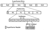
- a superframe includes a superframe header (SFH) and four frames (frames, F0, F1, F2, and F3).
- the size of each superframe is 20ms and the size of each frame is illustrated as 5ms, but is not limited thereto.
- the superframe header may be disposed at the earliest in the superframe, and a common control channel is assigned to the superframe header.
- the common control channel is a channel used for transmitting control information that can be commonly used by all terminals in a cell, such as information on frames or system information of a superframe.
- a synchronization channel for transmitting a synchronization signal may be arranged in the superframe header or adjacent to the superframe header.
- the synchronization signal may indicate cell information such as a cell ID.
- the superframe header includes a primary superframe header (P-SFH) and a secondary superframe header (S-SFH).
- P-SFH primary superframe header
- S-SFH secondary superframe header
- the main superframe header is included in the first frame of each superframe, and the main superframe header is configured as shown in the table below.
- the primary superframe header is included in every superframe and indicates whether the auxiliary superframe included in the current superframe is included and the update number of system information supported by the current superframe.
- the secondary superframe header is divided into three secondary superframe header subpackets (S-SFH SP) according to their characteristics, and each secondary superframe header subpackets are required for the mobile terminal to access the base station. Is used to broadcast the system information to the mobile terminal.
- Each auxiliary superframe header subpacket may be transmitted according to a different transmission period according to the nature of the included system information. For example, the auxiliary superframe header subpacket 1 may be transmitted in 2 superframe periods, the auxiliary superframe header subpacket 2 in 3 superframe periods, and the auxiliary superframe header subpacket 3 in 4 superframe periods.
- One frame includes a plurality of subframes (Subframe, SF0, SF1, SF2, SF3, SF4, SF5, SF6, SF7).
- Each subframe may be used for uplink or downlink transmission.
- the subframe may consist of 6 or 7 OFDM symbols, but this is only an example.
- a time division duplexing (TDD) scheme or a frequency division duplexing (FDD) scheme may be applied to the frame.
- TDD time division duplexing
- FDD frequency division duplexing
- each subframe is used for uplink transmission or downlink transmission at different times at the same frequency. That is, the subframes in the frame of the TDD scheme are classified into an uplink subframe and a downlink subframe in the time domain.
- each subframe is used for uplink transmission or downlink transmission at different frequencies at the same time. That is, subframes in the frame of the FDD scheme are divided into an uplink subframe and a downlink subframe in the frequency domain. Uplink transmission and downlink transmission occupy different frequency bands and may be simultaneously performed.
- Each subframe may include a subframe header.
- the subframe header may include radio resource allocation information of the subframe.
- the subframe includes at least one frequency partition.
- the frequency partition is composed of at least one Physical Resource Unit (PRU).
- PRU Physical Resource Unit
- the frequency partitions may include Localized PRUs and / or Distributed PRUs. Frequency partitioning may be used for other purposes such as Fractional Frequency Reuse (FFR) or Multicast and Broadcast Services (MBS).
- FFR Fractional Frequency Reuse
- MBS Multicast and Broadcast Services
- a PRU is defined as a basic physical unit for resource allocation that includes a plurality of consecutive OFDM symbols and a plurality of consecutive subcarriers.
- the number of OFDM symbols included in the PRU may be equal to the number of OFDM symbols included in one subframe. For example, when one subframe consists of 6 OFDM symbols, the PRU may be defined with 18 subcarriers and 6 OFDM symbols.
- Logical Resource Units are basic logical units for distributed resource allocation and localized resource allocation. The LRU is defined by a plurality of OFDM symbols and a plurality of subcarriers and includes pilots used in a PRU. Thus, the appropriate number of subcarriers in one LRU depends on the number of pilots assigned.
- DRUs Logical Distributed Resource Units
- the DRU includes subcarrier groups distributed in one frequency partition.
- the size of the DRU is equal to the size of the PRU.
- the smallest unit that forms a DRU is one subcarrier.
- Logical Contiguous Resource Units may be used to obtain frequency selective scheduling gains.
- the CRU includes a local subcarrier group.
- the size of the CRU is equal to the size of the PRU.
- the service state of the femto base station includes an out of service and a service recovery state.
- the service interruption means that the air interface by the femto base station is deactivated
- the service recovery means that the femto base station activates the air interface from the service interruption.
- the service outage of the femto base station may be divided into scheduled service outages and unscheduled service outages. For example, when it is necessary to reboot by software download / install or the like, or when a femto base station is scheduled to be shut down, the femto base station operates by scheduling its own service interruption. can do. Unscheduled service outages may occur when a femto base station fails to schedule service outages, such as a sudden power outage or backhaul link of a femto base station.
- FIG. 3 illustrates a method of performing a handover procedure according to a scheduled service interruption of a femto base station according to an embodiment of the present invention.
- UE # 1 is connected to base station # 1 (hereinafter, femto base station # 1) to transmit and receive data (S110), and UE # 2 is connected to femto base station # 1 to transmit and receive data (S115).
- base station # 1 hereinafter, femto base station # 1
- UE # 2 is connected to femto base station # 1 to transmit and receive data (S115).
- Femto base station # 1 schedules out of service (S120).
- the femto base station # 1 may schedule a service interruption according to a reboot for downloading / installing the software or an operation policy of the femtocell. That is, femto base station # 1 performs the scheduled service interruption.
- the femto base station # 1 can use the battery, if the main power of the femto base station # 1 is cut off, the scheduled service interruption process using the battery may be performed for a predetermined time.
- the scheduled service interruption of the femto base station can be performed when there is a terminal that performs data transmission and reception, all terminals receiving a service from the femto base station are in an idle mode or a sleep mode. In the case of the scheduled service interruption of the femto base station may be performed.
- Femto base station # 1 transmits the service unavailable information to the terminal (S130).
- the service unavailable information may be repeatedly transmitted at least two times until a scheduled service interruption through a broadcast message or a paging message.
- the service unavailable information may be an AAI_SON (Self Organizing Networks) -ADV message.
- the terminal # 1 and the terminal # 2 may receive service unavailable information and may regard the service unavailable information as a handover command message.
- a cell bar indication included in a superframe header (SFH) or a secondary superframe header (S-SFH) together with the transmission of service unavailable information is set to 1 so that it can be transmitted from another cell.
- the entry / reentry to the femto base station # 1 can be prevented.
- the cell prohibition indicator indicates whether the terminal is allowed to enter or reenter the network. If the cell prohibit indicator value is 0, the terminal is allowed to enter or reenter the network.
- the terminal attempting to enter / reenter the network through the femto base station # 1 confirms that the cell inhibit indicator value included in the SFH or S-SFH transmitted from the femto base station # 1 is set to 1 and does not perform network entry / reentry.
- the out of service information may include a reason for service interruption, an expected down time, an expected uptime, a recommended BSID, and the like.
- the estimated downtime represents the time when the service of the femto base station is stopped according to the scheduling of the service interruption, and the estimated recovery time is the time when the service of the femto base station is restored and started again, or until the service is restored after the service is stopped. Means the period of. Since the expected recovery time is an optional factor, it may or may not be included in the service interruption information.
- the UE After the estimated recovery time has elapsed, the UE, which has performed a handover to another base station due to service interruption, may scan the femto base station that was previously subscribed even if it is not instructed to return to the previous femto base station through the handover. Can be.
- the service interruption reason indicates a reason that a service such as a shutdown of a femto base station, a backhaul linkdown, or the like is interrupted. It can also indicate the meaning of resource coordination.
- resource coordination of the femto base station is performed according to interference mitigation that may affect some terminals originally subscribed to the femto base station # 1, the femto base station adjusts the resource to prevent service interruption of the subordinate terminal. It can also be used to convey meaning about information.
- the reason for the service interruption included in the service unavailable information may be in the form of a field having a size of 2 bits in detail, and the meaning when each bit value is shown in Table 2 below.
- the recommended base station refers to a potential base station that may be a target base station (target BS) to which the terminal in which the femto base station # 1 is serving is trying to hand over (HO).
- target BS target base station
- the recommended base station may be a base station or an adjacent base station to which the femto base station # 1 has delivered the context information (context information).
- the recommended base station may be a macro base station or another femto base station in which the femto base station # 1 and the cell region overlap each other.
- the recommended base station ID indicates identifier information of a base station or a neighboring base station to which the femto base station # 1 has transmitted information of a serviced terminal.
- the recommended base station ID may include at least one base station ID.
- the recommended base station may transmit information of a terminal on which the femto base station # 1 is serving.
- the terminal first considers any one of the recommended base stations as a target base station for handover.
- the service unavailable information may further include an indicator for informing whether the handover is coordinated when the handover is performed and allowing the terminal to determine what handover procedure to perform.
- Femto base station # 1 transmits the terminal information to the macro base station through a backbone network (S140). That is, the macro base station becomes a recommended base station.
- the femto base station # 1 transmits the terminal information to the macro base station so that handover of the terminal is performed more quickly.
- the macro base station may transmit an acknowledgment (ACK) signal in response to the transmission of the terminal information of the femto base station # 1, and may transmit a non-acknowledgement (NACK) signal as necessary (S145). .
- ACK acknowledgment
- NACK non-acknowledgement
- femto base station # 1 may store context information of a terminal in service.
- the information of the terminal may include basic capabilities and security capabilities.
- the information of the UE enables the AMS to perform an optimized reentry procedure to the femto base station # 1 when the femto base station # 1 is recovered to be able to provide a service again.
- terminal # 1 performs handover to base station # 2 (hereinafter, femto base station # 2), and terminal # 2 performs handover to macro base station.
- base station # 2 hereinafter, femto base station # 2
- UE # 2 may transmit handover information to femto base station # 1 if it is estimated that the handover will be performed within the expected interruption time (S150).
- the femto base station # 1 supports the handover procedure of the terminal # 2 before the service is stopped, and the terminal # 2 may perform network re-entry to the macro base station (S155).
- UE # 2 transmits a ranging request message for handover, and the macro base station transmits a ranging response message in response to the ranging request message.
- the ranging request message may include the recommended base station ID together with the serving base station ID.
- the macro base station may support the network re-entry of the terminal # 2 more efficiently by using the terminal information previously received from the femto base station # 1.
- Network reentry may be performed (S160). That is, the terminal # 1 inputs and transmits the macro base station ID, which is a recommended base station to which the terminal information is previously transmitted, to the serving base station ID included in the ranging request message.
- the femto base station # 2 checks the serving base station ID included in the ranging request message received from the terminal # 1 and requests the terminal information from the macro base station (S170).
- the macro base station transmits the terminal information to the femto base station # 2 (S175).
- the femto base station # 2 can efficiently support network re-entry of the terminal # 1 by obtaining terminal information from the macro base station, that is, the recommended base station.
- FIG. 4 illustrates a method of performing a handover procedure according to service recovery of a femto base station according to an embodiment of the present invention.
- a handover procedure of the UE is performed according to the backhaul link recovery of the femto base station after the backhaul linkdown of the femto base station and the deactivation of the air interface.
- the terminal # 1 and the terminal # 2 are connected to the femto base station # 1 to transmit and receive data (S210, S215).
- the femto base station # 1 deactivates the air interface when the backhaul link is disconnected for a predetermined time (S220).
- femto base station # 1 maintains the terminal information (for example, terminal ID list) that was serving.
- the terminal information stored in the femto base station # 1 efficiently supports reentry into the network when the backhaul link of the femto base station # 1 is normally restored and the terminals performing the handover to the neighbor base station perform handover back to the femto base station # 1. Can be used to
- the terminal # 2 performs a handover procedure to the macro base station to perform data transmission and reception with the macro base station (S230), and the terminal # 1 performs a handover procedure to the femto base station # 2 to perform data transmission and reception with the femto base station # 2. (S235) Let's do it.
- the handover procedure of UE # 1 and UE # 2 may be performed as described above with reference to FIG. 3.
- the femto base station # 1 notifies the neighbor base stations of the service recovery information when the backhaul link is restored (S240). That is, femto base station # 1 informs neighboring base stations of the service recovery information when the service for the terminal is restored.
- the service recovery information is transmitted to the current serving base station serving the terminal through an interface of a backhaul network.
- this figure illustrates a case in which the backhaul link is recovered, the present invention is not limited thereto and may include a case in which femto base station # 1 restarts a service.
- the service recovery information includes an ID of the femto base station # 1, state information of the femto base station # 1, and terminal information stored in the femto base station # 1.
- the state information of the femto base station means information such as initialization of the femto base station or recovery from backhaul linkdown.
- the terminal information includes the ID of the terminal that the femto base station provided the service.
- the macro base station After receiving the service recovery information, the macro base station checks the terminal ID included in the terminal information and transmits fast feedback information allocated to the corresponding terminal (terminal # 2) (S250). Fast feedback is used for the transmission of information requiring fast response from the base station.
- the fast feedback channel may include at least one PRU or CRU.
- the femto base station # 1 measures the fast feedback report of the terminal # 2 and transmits measurement information to the macro base station (S225). That is, the femto base station # 1 can measure the channel state of the terminal # 2 through the fast feedback report transmitted from the terminal # 2, and report this to the macro base station to determine whether to perform handover for the terminal # 2. .
- the channel state measurement information may be represented by a carrier to interference and noise ratio (CINR) or a received signal strength indication (RSSI).
- the macro base station determines whether to handover the terminal # 2 based on the measurement information received from the femto base station # 1 (S260). If it is determined that the channel state for the terminal # 2 received from the femto base station # 1 is superior to the threshold, the macro base station may determine to handover the terminal # 2 to the femto base station # 1.
- the base station may initiate a handover to the terminal back to the previous service providing femto base station.
- the previous service providing femto base station such as femto base station # 1 has the highest priority as the base station to be handed over.
- the macro base station When determining to handover the terminal # 2 to the femto base station # 1, the macro base station transmits a handover command message to the terminal # 2 (S270).
- Terminal # 2 may perform a handover procedure to femto base station # 1 according to the handover command message, reenter the network, and perform data transmission / reception with the femto base station # 1 (S275).
- the femto base station # 1 may support network reentry and data transmission / reception of the terminal # 2 using the terminal information stored therein.
- the femto base station # 2 receiving the service recovery information from the femto base station # 1 also performs the same procedure as the macro base station for the terminal # 1. In this case, if the terminal # 1 has already left the cell area of the femto base station # 1, the handover command message may not be transmitted. When the terminal # 1 leaves the cell area of the femto base station # 1 and the handover command message is not transmitted, the terminal # 1 may perform data transmission / reception with the femto base station # 2 as it is (S280).
- the handover procedure according to the backhaul link recovery of the femto base station may be applied to the initialization process of the femto base station.
- the femto base station transmits service start information to the base station or adjacent femto base station with the overlapped cell area.
- the service start information corresponds to the above service recovery information.
- the base station receiving the service start information informs the fast feedback information allocated to the serviced terminal in some cases, and the femto base station measures the channel state of the corresponding terminal using the fast feedback information, and CINR or RSSI indicating the channel state of the terminal. May transmit measurement information for a fast feedback channel that is greater than or equal to a predetermined threshold.
- the base station may request channel scanning from the femto base station or may command a handover to the femto base station.
- a processor such as a microprocessor, a controller, a microcontroller, an application specific integrated circuit (ASIC), or the like according to software or program code coded to perform the function.
- ASIC application specific integrated circuit
Abstract
Priority Applications (2)
| Application Number | Priority Date | Filing Date | Title |
|---|---|---|---|
| US13/381,898 US8694007B2 (en) | 2009-07-01 | 2010-07-01 | Method for providing and receiving reliable service in wireless communication system |
| JP2012519463A JP2012532554A (ja) | 2009-07-01 | 2010-07-01 | 無線通信システムにおける信頼性のあるサービスの提供および受信方法 |
Applications Claiming Priority (4)
| Application Number | Priority Date | Filing Date | Title |
|---|---|---|---|
| KR10-2009-0059585 | 2009-07-01 | ||
| KR20090059585 | 2009-07-01 | ||
| KR10-2010-0063608 | 2010-07-01 | ||
| KR1020100063608A KR20110002447A (ko) | 2009-07-01 | 2010-07-01 | 무선통신 시스템에서 신뢰성 있는 서비스의 제공 및 수신 방법 |
Publications (2)
| Publication Number | Publication Date |
|---|---|
| WO2011002250A2 true WO2011002250A2 (fr) | 2011-01-06 |
| WO2011002250A3 WO2011002250A3 (fr) | 2011-03-31 |
Family
ID=43411624
Family Applications (1)
| Application Number | Title | Priority Date | Filing Date |
|---|---|---|---|
| PCT/KR2010/004294 WO2011002250A2 (fr) | 2009-07-01 | 2010-07-01 | Procédé pour fournir et recevoir un service fiable dans un système de communication sans fil |
Country Status (1)
| Country | Link |
|---|---|
| WO (1) | WO2011002250A2 (fr) |
Cited By (2)
| Publication number | Priority date | Publication date | Assignee | Title |
|---|---|---|---|---|
| WO2013121761A1 (fr) * | 2012-02-14 | 2013-08-22 | 株式会社エヌ・ティ・ティ・ドコモ | Appareil de femto-station de base et système de fonctionnement |
| CN112994910A (zh) * | 2019-12-13 | 2021-06-18 | 中盈优创资讯科技有限公司 | 网络端口告警信息的处理方法及装置 |
Citations (3)
| Publication number | Priority date | Publication date | Assignee | Title |
|---|---|---|---|---|
| KR20000002300A (ko) * | 1998-06-18 | 2000-01-15 | 김영환 | 이동통신 시스템에서 호 서비스의 동적제어 방법 |
| KR100756193B1 (ko) * | 2006-05-25 | 2007-09-05 | 에스케이 텔레콤주식회사 | Wcdma와 cdma-2000 간의 서비스모드 전환 방법 및시스템 |
| US20090156213A1 (en) * | 2007-10-25 | 2009-06-18 | Spinelli Vincent | Interworking gateway for mobile nodes |
-
2010
- 2010-07-01 WO PCT/KR2010/004294 patent/WO2011002250A2/fr active Application Filing
Patent Citations (3)
| Publication number | Priority date | Publication date | Assignee | Title |
|---|---|---|---|---|
| KR20000002300A (ko) * | 1998-06-18 | 2000-01-15 | 김영환 | 이동통신 시스템에서 호 서비스의 동적제어 방법 |
| KR100756193B1 (ko) * | 2006-05-25 | 2007-09-05 | 에스케이 텔레콤주식회사 | Wcdma와 cdma-2000 간의 서비스모드 전환 방법 및시스템 |
| US20090156213A1 (en) * | 2007-10-25 | 2009-06-18 | Spinelli Vincent | Interworking gateway for mobile nodes |
Cited By (3)
| Publication number | Priority date | Publication date | Assignee | Title |
|---|---|---|---|---|
| WO2013121761A1 (fr) * | 2012-02-14 | 2013-08-22 | 株式会社エヌ・ティ・ティ・ドコモ | Appareil de femto-station de base et système de fonctionnement |
| CN103635889A (zh) * | 2012-02-14 | 2014-03-12 | 株式会社Ntt都科摩 | 毫微微基站装置、操作系统 |
| CN112994910A (zh) * | 2019-12-13 | 2021-06-18 | 中盈优创资讯科技有限公司 | 网络端口告警信息的处理方法及装置 |
Also Published As
| Publication number | Publication date |
|---|---|
| WO2011002250A3 (fr) | 2011-03-31 |
Similar Documents
| Publication | Publication Date | Title |
|---|---|---|
| US11696293B2 (en) | Communication system, base station and mobile terminal | |
| JP6910409B2 (ja) | 移動体通信システムおよび基地局装置 | |
| JP2023168478A (ja) | 移動体通信システムおよび基地局 | |
| US8331948B2 (en) | Method and apparatus of operating femto base station in wireless communication system | |
| US8565807B2 (en) | Transmission of a synchronization signal within a cellular telecommunication network with temporarily increased transmitting power | |
| US8989086B2 (en) | Methods and apparatus to support interference management in multi-tier wireless communication systems | |
| KR20110002447A (ko) | 무선통신 시스템에서 신뢰성 있는 서비스의 제공 및 수신 방법 | |
| US20180041324A1 (en) | Mobile communication system, base station device and relay device | |
| US8897258B2 (en) | Method of transmitting data for reducing interference in hierarchical cell structure | |
| CN102934496B (zh) | 异类网络中的小区搜索与测量 | |
| US20130303152A1 (en) | Method and apparatus for requesting inter-cell interference coordination and method and apparatus for processing inter-cell interference coordination request | |
| US20120015649A1 (en) | Methods and apparatus to support base station detection and selection in multi-tier wireless networks | |
| WO2010095876A2 (fr) | Appareil et procede permettant de realiser un transfert dans un systeme de communication sans fil | |
| KR20110039582A (ko) | 무선 통신들에서 주파수 우선순위 리스트들을 업데이트하는 장치들 및 방법들 | |
| KR20140092379A (ko) | 기지국에서의 간섭을 완화하도록 사용자 단말에게 지시하는 방법 | |
| KR20110023726A (ko) | 무선통신 시스템에서 펨토 기지국의 서비스 상태 정보 전송방법 | |
| WO2011002250A2 (fr) | Procédé pour fournir et recevoir un service fiable dans un système de communication sans fil | |
| KR101706350B1 (ko) | 계층적 셀 구조에서 간섭을 줄이는 데이터 전송방법 | |
| KR20110004329A (ko) | 무선통신 시스템에서 페이징 메시지 전송과정을 수행하는 방법 | |
| KR20120048446A (ko) | 통신 시스템에서 셀 간 간섭제어 방법 및 이를 적용한 장치 |
Legal Events
| Date | Code | Title | Description |
|---|---|---|---|
| 121 | Ep: the epo has been informed by wipo that ep was designated in this application |
Ref document number: 10794385 Country of ref document: EP Kind code of ref document: A2 |
|
| WWE | Wipo information: entry into national phase |
Ref document number: 13381898 Country of ref document: US |
|
| NENP | Non-entry into the national phase |
Ref country code: DE |
|
| WWE | Wipo information: entry into national phase |
Ref document number: 2012519463 Country of ref document: JP |
|
| 122 | Ep: pct application non-entry in european phase |
Ref document number: 10794385 Country of ref document: EP Kind code of ref document: A2 |