WO2011001725A1 - Liquid crystal display device and light source control method - Google Patents
Liquid crystal display device and light source control method Download PDFInfo
- Publication number
- WO2011001725A1 WO2011001725A1 PCT/JP2010/055346 JP2010055346W WO2011001725A1 WO 2011001725 A1 WO2011001725 A1 WO 2011001725A1 JP 2010055346 W JP2010055346 W JP 2010055346W WO 2011001725 A1 WO2011001725 A1 WO 2011001725A1
- Authority
- WO
- WIPO (PCT)
- Prior art keywords
- liquid crystal
- duty
- crystal display
- response speed
- display device
- Prior art date
Links
Images


Classifications
-
- G—PHYSICS
- G09—EDUCATION; CRYPTOGRAPHY; DISPLAY; ADVERTISING; SEALS
- G09G—ARRANGEMENTS OR CIRCUITS FOR CONTROL OF INDICATING DEVICES USING STATIC MEANS TO PRESENT VARIABLE INFORMATION
- G09G3/00—Control arrangements or circuits, of interest only in connection with visual indicators other than cathode-ray tubes
- G09G3/20—Control arrangements or circuits, of interest only in connection with visual indicators other than cathode-ray tubes for presentation of an assembly of a number of characters, e.g. a page, by composing the assembly by combination of individual elements arranged in a matrix no fixed position being assigned to or needed to be assigned to the individual characters or partial characters
- G09G3/2007—Display of intermediate tones
- G09G3/2018—Display of intermediate tones by time modulation using two or more time intervals
- G09G3/2022—Display of intermediate tones by time modulation using two or more time intervals using sub-frames
-
- G—PHYSICS
- G09—EDUCATION; CRYPTOGRAPHY; DISPLAY; ADVERTISING; SEALS
- G09G—ARRANGEMENTS OR CIRCUITS FOR CONTROL OF INDICATING DEVICES USING STATIC MEANS TO PRESENT VARIABLE INFORMATION
- G09G3/00—Control arrangements or circuits, of interest only in connection with visual indicators other than cathode-ray tubes
- G09G3/20—Control arrangements or circuits, of interest only in connection with visual indicators other than cathode-ray tubes for presentation of an assembly of a number of characters, e.g. a page, by composing the assembly by combination of individual elements arranged in a matrix no fixed position being assigned to or needed to be assigned to the individual characters or partial characters
- G09G3/34—Control arrangements or circuits, of interest only in connection with visual indicators other than cathode-ray tubes for presentation of an assembly of a number of characters, e.g. a page, by composing the assembly by combination of individual elements arranged in a matrix no fixed position being assigned to or needed to be assigned to the individual characters or partial characters by control of light from an independent source
- G09G3/3406—Control of illumination source
-
- G—PHYSICS
- G09—EDUCATION; CRYPTOGRAPHY; DISPLAY; ADVERTISING; SEALS
- G09G—ARRANGEMENTS OR CIRCUITS FOR CONTROL OF INDICATING DEVICES USING STATIC MEANS TO PRESENT VARIABLE INFORMATION
- G09G2310/00—Command of the display device
- G09G2310/02—Addressing, scanning or driving the display screen or processing steps related thereto
- G09G2310/0232—Special driving of display border areas
-
- G—PHYSICS
- G09—EDUCATION; CRYPTOGRAPHY; DISPLAY; ADVERTISING; SEALS
- G09G—ARRANGEMENTS OR CIRCUITS FOR CONTROL OF INDICATING DEVICES USING STATIC MEANS TO PRESENT VARIABLE INFORMATION
- G09G2310/00—Command of the display device
- G09G2310/02—Addressing, scanning or driving the display screen or processing steps related thereto
- G09G2310/0243—Details of the generation of driving signals
- G09G2310/0251—Precharge or discharge of pixel before applying new pixel voltage
-
- G—PHYSICS
- G09—EDUCATION; CRYPTOGRAPHY; DISPLAY; ADVERTISING; SEALS
- G09G—ARRANGEMENTS OR CIRCUITS FOR CONTROL OF INDICATING DEVICES USING STATIC MEANS TO PRESENT VARIABLE INFORMATION
- G09G2320/00—Control of display operating conditions
- G09G2320/02—Improving the quality of display appearance
- G09G2320/0257—Reduction of after-image effects
-
- G—PHYSICS
- G09—EDUCATION; CRYPTOGRAPHY; DISPLAY; ADVERTISING; SEALS
- G09G—ARRANGEMENTS OR CIRCUITS FOR CONTROL OF INDICATING DEVICES USING STATIC MEANS TO PRESENT VARIABLE INFORMATION
- G09G2320/00—Control of display operating conditions
- G09G2320/04—Maintaining the quality of display appearance
- G09G2320/041—Temperature compensation
-
- G—PHYSICS
- G09—EDUCATION; CRYPTOGRAPHY; DISPLAY; ADVERTISING; SEALS
- G09G—ARRANGEMENTS OR CIRCUITS FOR CONTROL OF INDICATING DEVICES USING STATIC MEANS TO PRESENT VARIABLE INFORMATION
- G09G2320/00—Control of display operating conditions
- G09G2320/06—Adjustment of display parameters
- G09G2320/0626—Adjustment of display parameters for control of overall brightness
- G09G2320/0633—Adjustment of display parameters for control of overall brightness by amplitude modulation of the brightness of the illumination source
-
- G—PHYSICS
- G09—EDUCATION; CRYPTOGRAPHY; DISPLAY; ADVERTISING; SEALS
- G09G—ARRANGEMENTS OR CIRCUITS FOR CONTROL OF INDICATING DEVICES USING STATIC MEANS TO PRESENT VARIABLE INFORMATION
- G09G2320/00—Control of display operating conditions
- G09G2320/06—Adjustment of display parameters
- G09G2320/0626—Adjustment of display parameters for control of overall brightness
- G09G2320/064—Adjustment of display parameters for control of overall brightness by time modulation of the brightness of the illumination source
-
- G—PHYSICS
- G09—EDUCATION; CRYPTOGRAPHY; DISPLAY; ADVERTISING; SEALS
- G09G—ARRANGEMENTS OR CIRCUITS FOR CONTROL OF INDICATING DEVICES USING STATIC MEANS TO PRESENT VARIABLE INFORMATION
- G09G2320/00—Control of display operating conditions
- G09G2320/06—Adjustment of display parameters
- G09G2320/0626—Adjustment of display parameters for control of overall brightness
- G09G2320/0646—Modulation of illumination source brightness and image signal correlated to each other
-
- G—PHYSICS
- G09—EDUCATION; CRYPTOGRAPHY; DISPLAY; ADVERTISING; SEALS
- G09G—ARRANGEMENTS OR CIRCUITS FOR CONTROL OF INDICATING DEVICES USING STATIC MEANS TO PRESENT VARIABLE INFORMATION
- G09G2320/00—Control of display operating conditions
- G09G2320/10—Special adaptations of display systems for operation with variable images
- G09G2320/103—Detection of image changes, e.g. determination of an index representative of the image change
-
- G—PHYSICS
- G09—EDUCATION; CRYPTOGRAPHY; DISPLAY; ADVERTISING; SEALS
- G09G—ARRANGEMENTS OR CIRCUITS FOR CONTROL OF INDICATING DEVICES USING STATIC MEANS TO PRESENT VARIABLE INFORMATION
- G09G2340/00—Aspects of display data processing
- G09G2340/04—Changes in size, position or resolution of an image
- G09G2340/0407—Resolution change, inclusive of the use of different resolutions for different screen areas
- G09G2340/0435—Change or adaptation of the frame rate of the video stream
Definitions
- the present invention relates to a liquid crystal display device which is a display device, and a method for controlling a light source mounted on the liquid crystal display device.
- a backlight unit for supplying light is usually mounted on the liquid crystal display panel.
- the light source is an LED (Light Emitting Diode).
- LED is driven by the well-known PWM (Pulse Width Modulation) control.
- PWM Pulse Width Modulation
- the LEDs are set to be turned on and off in time series within one frame period (in one vertical period).
- a so-called hold-type display device such as a liquid crystal display device
- the same image is displayed over one frame period in continuous frame images. Then, a human will continue to see an uninterrupted image, and the image may feel afterimages, blurs, and the like.
- the liquid crystal display device of Patent Document 1 performs lighting and extinguishing in a time series in one frame period, and pseudo-displays an image of one frame in a discontinuous manner (in this way, the extinguishing time is as described above). Is referred to as black insertion). That is, the liquid crystal display device of Patent Document 1 is driven like an impulse type display device ⁇ for example, a display device equipped with a CRT (Cathode Ray Tube) ⁇ . Thereby, this liquid crystal display device aims at the improvement of moving image performance, for example.
- an impulse type display device for example, a display device equipped with a CRT (Cathode Ray Tube) ⁇ .
- the liquid crystal display panel displays an image by changing the transmittance of light from the backlight unit according to the inclination of the liquid crystal molecules. Therefore, the image quality is easily affected by the tilting speed (response speed) of the liquid crystal molecules. Then, depending on the response speed, the afterimage is not improved only by changing the lighting time and the extinguishing time of the LED, and further, image quality degradation such as multiple contours occurs.
- An object of the present invention is to provide a liquid crystal display device or the like that improves image quality by controlling the light source in consideration of the characteristics of the liquid crystal.
- a liquid crystal display device includes a liquid crystal display panel that displays an image by having a liquid crystal that changes its orientation in response to application of a voltage, and a PWM dimming light source that emits light to be supplied to the liquid crystal display panel And a control unit for controlling the liquid crystal display panel and the backlight unit.
- the liquid crystal is included in the liquid crystal display panel and interposed between the two substrates, and the first electrode and the second electrode are arranged facing each other on one surface facing the liquid crystal side of one substrate. .
- the liquid crystal molecules contained in the liquid crystal are positive, and are aligned so that their major axes are along the vertical direction of the two substrates when no voltage is applied to both electrodes.
- control unit acquires response speed data of the orientation change of the liquid crystal molecules in the liquid crystal, and changes the duty of the PWM dimming signal according to the response speed data.
- the control unit has at least one arbitrary response speed data threshold value, sets a plurality of arbitrary response speed data ranges with the response speed data threshold as a boundary, and changes Duty for each response speed data range. desirable. If this is the case, the Duty can be changed in multiple steps, and image quality problems can be further prevented.
- the duty is changed for each response speed data range so as to be opposite to the magnitude relation of data values in a plurality of response speed data ranges.
- control unit sets two response speed data ranges with one response speed data threshold, it is desirable to control as follows. That is, if the response speed data is included in the response speed data range that is higher than the response speed data threshold, the control unit drives the light source at an arbitrary X% or less duty, while less than the response speed data threshold. When response speed data is included in the low-speed response speed data range, the light source is driven with a duty exceeding an arbitrary X% (X% is preferably 50%).
- liquid crystal display device displays an image similar to an impulse-type display device, and the image quality can be improved.
- liquid light with a relatively low response speed is supplied continuously at short intervals, light is supplied to liquid crystal molecules that do not reach a predetermined angle. As a result, image quality defects occur.
- the light source is driven with a relatively large duty to prevent image quality defects. Therefore, in this liquid crystal display device, the image quality can be improved according to the response speed of the liquid crystal.
- the light source is not only the PWM dimming method but also the current dimming method, and it is preferable that the control unit drives the light source by changing the current value according to the duty. In this way, the difference between the luminance corresponding to the duty before change and the luminance corresponding to the duty after change is reduced.
- control unit 100% so that the integrated amount of light emission in one cycle period of the PWM dimming signal matches the integrated amount of light emission in 100% duty in a time corresponding to one cycle period. It is desirable to change the current value of the PWM dimming signal when driving with a duty other than. With this configuration, the liquid crystal display device can improve the image quality by changing the duty according to the response speed of the liquid crystal while maintaining high luminance.
- the liquid crystal display device includes a first temperature sensor that measures the temperature of the liquid crystal, and the control unit stores response speed data of liquid crystal molecules depending on the liquid crystal temperature, and at least one of the response speed data. It is desirable that the response speed data is acquired by associating the temperature data of the first temperature sensor with the liquid crystal temperature.
- the liquid crystal display device has various functions in order to improve the image quality. Therefore, it is desirable for the control unit to set the duty corresponding to these functions.
- control unit includes a histogram unit that generates histogram data indicating a frequency distribution with respect to gradations by converting the video data into a histogram. Then, the control unit classifies all the gradations of the histogram data, and determines whether the occupancy rate in at least one specific gradation range of the divided gradation ranges exceeds or is less than the occupancy threshold value. .
- the control unit increases the duty when the occupation ratio threshold is exceeded to be higher than the duty when the occupation ratio threshold is less than or equal to the duty ratio when the occupation ratio threshold is exceeded or less. Lower than.
- the control unit increases the duty when exceeding the occupancy threshold, while the duty when exceeding the occupancy threshold is higher than the duty when less than the occupancy threshold, and the duty when exceeding the occupancy threshold
- the current value of the PWM dimming signal is changed corresponding to the duty. In this case, Duty is set corresponding to the image quality improvement function using the histogram data, and the image quality can be further improved.
- the liquid crystal display device includes a first temperature sensor that measures the temperature of the liquid crystal, and the control unit includes a storage unit that stores an occupancy threshold value. It is desirable that at least one of the occupation ratio threshold values can be changed according to the temperature data of the first temperature sensor.
- the duty is set corresponding to the function of improving the image quality using the histogram data
- the temperature data is 20 ° C.
- the specific floor It is desirable that the gradation range is 0 to 128 of the entire gradation range of 0 to 255, and the occupancy threshold is 50%.
- control unit includes an FRC processing unit that performs frame rate control processing. And it is desirable for the control unit to change the current value of the duty or the duty and PWM dimming signals according to the presence / absence of the frame rate control processing of the FRC processor. In this case, Duty is set corresponding to ON / OFF of the FRC process, and the image quality can be further improved.
- the duty when there is a frame rate control process is preferably lower than the duty when there is no frame rate control process.
- control unit includes a viewing mode setting unit that switches the viewing mode of the liquid crystal display panel.
- the control unit selects the duty mode according to the selected viewing mode.
- the viewing mode setting unit Since PWM setting (setting of the PWM dimming signal Duty and current value) is possible for each viewing mode, the viewing mode setting unit performs high movie level viewing mode and low movie depending on the movie level of the video data.
- the level viewing mode it is desirable that the duty is changed for each selected viewing mode so as to be inversely related to the moving image level relationship in the plurality of viewing modes.
- the viewing mode setting unit performs high contrast level viewing mode and low contrast according to the contrast level of the video data.
- the level viewing mode it is desirable that the duty is changed for each selected viewing mode so as to be inversely related to the contrast level of the plurality of viewing modes.
- control unit obtains external illuminance data and changes the current value of the duty or duty and PWM dimming signal according to the illuminance data.
- the duty is set corresponding to the brightness of the environment where the liquid crystal display device is placed, and the image quality can be further improved.
- the duty is changed for each illuminance data range so as to be opposite to the magnitude relationship of the data values for each of the plurality of illuminance data ranges.
- the liquid crystal display device includes an illuminance sensor that measures external illuminance, and the illuminance data is preferably measured illuminance of the illuminance sensor.
- control unit synchronizes the last timing in one frame period with the last timing in the high period in the PWM dimming signal.
- no light is supplied at the initial stage of tilting of the liquid crystal molecules. That is, light is not supplied to the liquid crystal molecules that have not reached the predetermined angle, and as a result, image quality defects are less likely to occur.
- control unit matches the low period of the PWM dimming signal in accordance with the period of at least one frame in consecutive frames.
- the liquid crystal display device there are a plurality of light sources, and the light source is partially arranged on the surface of the liquid crystal display panel so that light can be supplied. Therefore, a plurality of light sources are classified, and the classified one or plural light sources are set as the classified light sources. Then, it is desirable for the control unit to change the current value of the duty or the duty and PWM dimming signal for each segmented light source.
- the segmented light source irradiates light in a line shape within the surface of the liquid crystal display panel, or irradiates light according to a regularly divided block within the surface, or It is desirable to irradiate light according to a partial area in the plane.
- control unit includes a function of overdriving the voltage applied to the liquid crystal, and it is desirable to change the current value of the duty or duty and PWM dimming signals according to the presence or absence of overdrive. This is because the image quality of the liquid crystal display device can be improved even with such control.
- the liquid crystal is included in the liquid crystal display panel, interposed between the two substrates, and on one surface facing the liquid crystal side of one substrate, the first electrode and the second electrode Line up facing each other.
- the liquid crystal molecules contained in the liquid crystal are positive, and are aligned so that their major axes are along the vertical direction of the two substrates when no voltage is applied to both electrodes.
- Such a liquid crystal display device in particular, a liquid crystal display panel having a liquid crystal whose orientation is changed in response to application of a voltage, and a backlight unit having a built-in PWM dimming light source that emits light to be supplied to the liquid crystal display panel ,
- the light source is controlled by the following control method. That is, the method includes the steps of obtaining response speed data of the orientation change of liquid crystal molecules in the liquid crystal and changing the duty of the PWM dimming signal according to the response speed data.
- the liquid crystal display device as described above, in particular, a liquid crystal display panel having a liquid crystal whose orientation is changed in response to application of a voltage, and a PWM dimming light source that emits light to be supplied to the liquid crystal display panel.
- the light source is controlled by the following light source control program. That is, response speed data of the orientation change of the liquid crystal molecules in the liquid crystal is obtained, and the control unit is caused to change the duty of the PWM dimming signal according to the response speed data.
- the light source is controlled to emit light according to the tilt state of the liquid crystal molecules that influence the transmittance of the liquid crystal display panel. Therefore, image quality defects (such as multiple contours) that tend to occur according to the degree of inclination of the liquid crystal molecules are prevented.
- FIG. 3 is a block diagram of a liquid crystal display device.
- FIG. 3 is a block diagram in which a part of a block diagram of a liquid crystal display device is extracted and detailed.
- FIG. 3 is a block diagram in which a part of a block diagram of a liquid crystal display device is extracted and detailed.
- These are the fragmentary sectional views of a liquid crystal display panel. These are perspective views which show the orientation of liquid crystal molecules when no voltage is applied (in the case of OFF) in the MVA mode (slit type) liquid crystal. These are perspective views which show the orientation of liquid crystal molecules when a voltage is applied (in the case of ON) in a MVA mode (slit type) liquid crystal.
- FIG. 3 is a perspective view showing the orientation of liquid crystal molecules in a IPS mode liquid crystal when no voltage is applied (when OFF). These are perspective views which show the orientation of liquid crystal molecules when a voltage is applied (when ON) in an IPS mode liquid crystal.
- FIG. 3 is a perspective view showing a comb-like pixel electrode and a comb-like counter electrode. These are top views which show the screen of the liquid crystal display panel which displayed the person image.
- top views which show the screen of the liquid crystal display panel which displayed the black image and the white image. These are top views which show the screen of the liquid crystal display panel which displayed the black image and the white image. These are top views which show the screen of the liquid crystal display panel which displayed the black image and the white image. These are top views which show the screen of the liquid crystal display panel which displayed the black image and the white image. Shows the tilt amount of the liquid crystal molecules with respect to time, the waveform of the PWM dimming signal, and the luminance when the light of the LED driven by the PWM dimming signal of 100% duty is supplied to the liquid crystal having a relatively slow response speed. It is the graph which showed the change.
- Fig. 14 is a table summarizing image quality evaluations that can be derived from Figs. These are tables showing the relationship between the response speed of liquid crystal molecules and the duty factor (black insertion rate) of the PWM dimming signal.
- FIG. 23B is an explanatory diagram showing the relationship between the luminance of a PWM dimming signal having a current value adjusted to have the same luminance as the luminance of 100% Duty in FIG. 23A (where Duty is 80%) .
- FIG. 23B is an explanatory diagram showing the relationship between the luminance of a PWM dimming signal having a current value adjusted to have the same luminance as the luminance of 100% Duty in FIG. 23A (where Duty is 60%) .
- FIG. 23B is an explanatory diagram showing the relationship between the luminance of a PWM dimming signal having a current value adjusted to have the same luminance as the luminance of 100% Duty in FIG. 23A (where Duty is 60%) .
- FIG. 23B is an explanatory diagram showing the relationship between the luminance of a PWM dimming signal having a current value adjusted to have the same luminance as the luminance of 100% Duty in FIG. 23A (where Duty is 50%) .
- FIG. 3 is a block diagram of a liquid crystal display device.
- FIG. 3 is a block diagram in which a part of a block diagram of a liquid crystal display device is extracted and detailed.
- FIG. 3 is a block diagram in which a part of a block diagram of a liquid crystal display device is extracted and detailed. Shows the tilt amount of the liquid crystal molecules with respect to time, the waveform of the PWM dimming signal, and the luminance when the light of the LED driven by the PWM dimming signal of 50% duty is supplied to the liquid crystal having a relatively slow response speed. It is the graph which showed change (however, the drive frequency of PWM dimming signal 120Hz).
- FIG. 3 is an exploded perspective view of a liquid crystal display device. These are plan views in which a liquid crystal display panel displaying a white image at the center and a black image around the white image, and a backlight unit corresponding to the image of the liquid crystal display panel are shown.
- FIG. 3 is an exploded perspective view of a liquid crystal display device.
- FIG. 4 is a perspective view showing the alignment of liquid crystal molecules in a VA-IPS mode liquid crystal when no voltage is applied (OFF).
- FIG. 4 is a perspective view showing the orientation of liquid crystal molecules in a VA-IPS mode liquid crystal when a voltage is applied (when ON). Is a graph showing the relationship between the gradation value and the response time of liquid crystal molecules (provided that the liquid crystal temperature is relatively high in a VA-IPS mode liquid crystal). Is a graph showing the relationship between the gradation value and the response time of liquid crystal molecules (provided that the liquid crystal temperature is relatively low in a VA-IPS mode liquid crystal). Is a graph showing the relationship between the gradation value and the response time of liquid crystal molecules (provided that the liquid crystal temperature is relatively high in MVA mode, IPS mode, and VA-IPS mode liquid crystals).
- VA-IPS mode Is a table showing the relationship between the occupation ratio of the specific gradation range used in the video signal support function, the luminance, the duty of the PWM dimming signal, and the drive frequency of the PWM dimming signal (however, Liquid crystal is VA-IPS mode).
- Liquid crystal display device> 1 to 3 are block diagrams showing various members related to the liquid crystal display device 90 (note that FIGS. 2 and 3 are block diagrams in which a part of FIG. 1 is extracted and detailed).
- the liquid crystal display device 90 includes a liquid crystal display panel 60, a backlight unit 70, a gate driver 81, a source driver 82, a panel thermistor 83, an environmental illuminance sensor 84, an LED driver 85, and an LED thermistor 86.
- the liquid crystal display panel 60 sandwiches the liquid crystal 61 (liquid crystal molecules 61M) between the active matrix substrate 62 and the counter substrate 63 (see FIG. 4 described later), and seals the liquid crystal 61 using a sealing material (not shown).
- the active matrix substrate 62 is arranged such that the gate signal lines and the source signal lines intersect with each other, and further, at the intersection of both signal lines, a switching element (for example, thin) required for adjusting the applied voltage to the liquid crystal 61. Film Transistor) is placed.
- the backlight unit 70 includes a light source (light emitting element) such as an LED (Light Emitting Diode) 71 as shown in FIG. 1, for example, and supplies light from the LED 71 to the non-light emitting liquid crystal display panel 60. To do. Then, in the liquid crystal display device 90, the alignment of the liquid crystal molecules 61M is adjusted according to the applied voltage, so that the transmittance of the liquid crystal 61 changes partially (in short, the light from the backlight unit 70 is externally transmitted). The amount of light transmitted through the screen changes), and the display image changes.
- a light source such as an LED (Light Emitting Diode) 71 as shown in FIG. 1, for example
- LEDs 71 included in the backlight unit 70.
- LED71 which emits white light, red light, green light, or blue light is mentioned.
- the backlight light is also white due to the fact that all the LEDs 71 mounted on the backlight unit 70 are of the white light emitting type.
- white there are many ways to generate white.
- it may be an LED 71 that includes a red LED chip, a green LED chip, and a blue LED chip, and generates white with mixed colors, or may be an LED 71 that generates white by using fluorescent light emission.
- the LED 71 included in the backlight unit 70 includes a red light emitting LED 71, a green light emitting LED 71, and a blue light emitting type. LED71.
- the arrangement of the LEDs 71 is not particularly limited, and for example, as shown in FIG. 1, a matrix arrangement is given as an example.
- the LED 71 is driven by a known PWM (Pulse Width Modulation) control.
- the gate driver 81 is a driver that supplies a gate signal G-TS that is a control signal (timing signal) of the switching element to the gate signal line of the liquid crystal display panel 60.
- the gate signal G-TS is generated by the control unit 1.
- the source driver 82 writes a pixel writing signal (LCD video signal VD-Sp ′ [led] or LCD video signal VD-Sp to the source signal line of the liquid crystal display panel 60 as an example of image data. [led]); a driver that supplies details). More specifically, the source driver 82 supplies a write signal to the source signal line based on the timing signal S-TS generated by the control unit 1 (note that the write signal and the timing signal S-TS are supplied by the control unit 1). Generated).
- the panel thermistor (first temperature sensor) 83 is a temperature sensor that measures the temperature of the liquid crystal display panel 60, specifically, the temperature of the liquid crystal 61 included in the liquid crystal display panel 60. Details of the use of the panel thermistor 83 will be described later.
- the ambient illuminance sensor 84 is a photometric sensor that measures the illuminance of the environment where the liquid crystal display device 90 is placed. Details of the use of the environmental illumination sensor 84 will be described later.
- the LED driver 85 supplies the control signal (VD-Sd ′ [W ⁇ A]) of the LED 71 to the LED 71 based on the timing signal (L-TS) generated by the control unit 1 ⁇ note that the control signal of the LED 71 Is generated by the control unit 1 ⁇ . More specifically, the LED driver 85 controls the lighting of the LEDs 71 in the backlight unit 70 based on signals from the LED controller 30 (PWM dimming signal VD-Sd ′ [W ⁇ A], timing signal L-TS).
- the LED thermistor 86 is a temperature sensor that measures the temperature of the LED 71 mounted on the backlight unit 70. Details of the use of the LED thermistor 86 will be described later.
- the LED luminance sensor 87 is a photometric sensor that measures the luminance of the LED 71. Details of the use of the LED luminance sensor 87 will be described later.
- the control unit 1 is a control unit that generates the various signals described above, and includes a main microcomputer (main microcomputer) 51, a video signal processing unit 10, a liquid crystal display panel controller (LCD controller) 20, and an LED controller 30.
- main microcomputer main microcomputer
- video signal processing unit video signal processing unit
- LCD controller liquid crystal display panel controller
- LED controller 30 LED controller
- the main microcomputer 51 supervises various controls related to the video signal processing unit 10, the liquid crystal display panel controller 20, and the LED controller 30 included in the control unit 1 (note that the main microcomputer 51 is controlled by this). LED controller 30 may be collectively referred to as a microcomputer unit 50).
- the video signal processing unit 10 includes a timing adjustment unit 11, a histogram processing unit 12, an arithmetic processing unit 13, a duty setting unit 14, a current value setting unit 15, a viewing mode setting unit 16, and a memory 17. Including.
- the timing adjustment unit 11 receives an initial image signal (initial image signal F-VD) from an external signal source.
- the initial image signal F-VD is, for example, a television signal, and includes a video signal and a synchronization signal synchronized with the video signal (the video signal includes, for example, a red video signal, a green video signal, a blue video signal, Composed of luminance signals).
- the timing adjustment unit 11 generates a new synchronization signal (clock signal CLK, vertical synchronization signal VS, horizontal synchronization signal HS, etc.) required for image display on the liquid crystal display panel 60 from this synchronization signal. Then, the timing adjustment unit 11 transmits the generated new synchronization signal to the liquid crystal display panel controller 20 and the microcomputer unit 50 (see FIGS. 1 and 2).
- the histogram processing unit 12 receives the initial image signal F-VD, and histograms the video signal (video data) included in the initial image signal F-VD. More specifically, the histogram processing unit 12 acquires a frequency distribution for each gradation in the initial image signal F-VD for each frame.
- the data to be histogrammed is not limited to the initial image signal F-VD.
- a separator LED signal VD-Sd a separator LCD signal VD-Sp, an LCD video signal VD-Sp [led], or an LCD video signal VD-Sp ′ [led] subjected to frame rate control processing, which will be described later
- Histogram processing may be performed.
- these various video signals (video data) can be histogrammed ⁇ .
- the histogram data is assumed to be histogram data HGM.
- the histogram data HGM is transmitted to the arithmetic processing unit 13 by the histogram processing unit 12.
- the arithmetic processing unit 13 receives the initial image signal F-VD and uses the initial image signal F-VD as a signal suitable for driving the backlight unit 70 (specifically, the LED 71) and for driving the liquid crystal display panel 60. To separate the signal. Then, the arithmetic processing unit 13 transmits a separator LED signal VD-Sd suitable for the LED 71 in the initial image signal F-VD to the duty setting unit 14.
- the arithmetic processing unit 13 corrects the separator LCD signal VD-Sp suitable for the liquid crystal display panel 60 in the initial image signal F-VD, and then transmits it to the liquid crystal display panel controller 20.
- This correction process takes into account a control signal (PWM dimming signal VD-Sd [W ⁇ A]) of the LED 71, which will be described later (the separator LED signal VD-Sp subjected to the correction process is used for the LCD).
- the arithmetic processing unit 13 may transmit the separator LCD signal VD-Sp to the histogram processing unit 12 in order to form a histogram.
- the arithmetic processing unit 13 uses the histogram data HGM, the histogram data HGM [S] of the average signal level (ASL), and the histogram data HGM [S] of the average luminance level (Average Luminance Level; ALL). L] is determined.
- the arithmetic processing unit 13 performs the initial image signal F-VD, the separator LED signal VD-Sd, the separator LCD signal VD-Sp, the LCD video signal VD-Sp [led], or the LCD video signal VD-Sp ′. From [led], the histogram data HGM of at least one of the average signal level ASL and the average luminance level ALL can be obtained, and further transmitted to the duty setting unit 14.
- the arithmetic processing unit 13 can also obtain at least one of the average value of the average signal level ASL and the average value of the average luminance level ALL, and further transmits it to the duty setting unit 14. Note that the histogram processing unit 12 and the arithmetic processing unit 13 perform various processing related to various histogram data HGM, and thus are referred to as a histogram unit 18.
- the duty setting unit 14 receives the separator LED signal VD-Sd. Further, the duty setting unit 14 receives the histogram data HGM from the arithmetic processing unit 13. In addition, the duty setting unit 14 receives a signal (memory data DM) from a memory 17 described later, and also includes a viewing mode setting unit 16, a panel thermistor 83, and an LED controller 30 (more specifically, an FRC processing unit 21 described later). Also, at least one signal of the environmental illumination sensor 84 is received.
- the duty setting unit 14 generates a PWM dimming signal suitable for controlling the LED 71 (details will be described later). Specifically, the duty setting unit 14 sets the duty in the PWM dimming signal (note that the PWM dimming signal VD-Sd [W ])
- Duty is the ratio of the period during which the LED 71 is lit in one cycle of the PWM dimming signal (AC signal). That is, when the duty is 100%, it means that the LED 71 is continuously lit for one cycle (conversely, when the duty is 60%, the LED 71 is turned off during the 40% period during one cycle. is doing).
- the current value setting unit 15 receives the PWM dimming signal VD-Sd [W] from the duty setting unit 14 and changes the current value of the PWM dimming signal VD-Sd [W]. Details of the variable current value will be described later. Note that the PWM dimming signal VD-Sd [W] whose current value is appropriately set is the PWM dimming signal VD-Sd [W ⁇ A]. The PWM dimming signal VD-Sd [W ⁇ A] is transmitted by the current value setting unit 15 to the microcomputer unit 50 (specifically, the LED controller 30) and also to the arithmetic processing unit 13. .
- the viewing mode setting unit 16 displays an image according to the type of image displayed on the liquid crystal display panel 60, the environment of the place where the liquid crystal display device 90 is placed, or the viewer's preference (desired contrast ratio, etc.). Define the format (viewing mode).
- the viewing mode setting unit 16 can set the following viewing modes, for example.
- Sports mode A viewing mode suitable for displaying fast moving images such as soccer players. That is, a viewing mode with a relatively high video level.
- Natural mode A viewing mode suitable for displaying images with gentle movements such as news programs. That is, a viewing mode with a relatively low video level.
- Dynamic mode A viewing mode that emphasizes the contrast between white and black images. That is, a viewing mode in which the contrast level is relatively high.
- Cinema mode A viewing mode that does not accentuate the contrast between white and black images. That is, a viewing mode in which the contrast level is relatively low.
- Standard mode An intermediate viewing mode between dynamic mode and cinema mode.
- the viewing mode setting unit 16 performs the high movie level viewing mode or the low movie level viewing according to the movie level of the video signal (video data).
- a mode can be set (however, it is not always a two-level level setting).
- the viewing mode setting unit 16 selects the high contrast level viewing mode, the medium contrast level viewing mode, or the low contrast depending on the contrast level of the video signal (video data).
- Level viewing mode can be set (however, the level setting is not limited to three levels).
- the memory (storage unit) 17 stores various data tables necessary for the duty setting of the duty setting unit 14, various threshold data (threshold values), and the like.
- the memory 17 includes a temperature-speed data table in which the temperature of the panel thermistor 83 is associated with the response speed Vr of the liquid crystal molecules 61M. Further, the memory 17 stores a certain response speed Vr in the temperature-speed data table as a threshold (response speed data threshold).
- the number of threshold values may be singular or plural.
- the memory 17 stores a threshold value (gradation threshold data) for classifying all gradations in the histogram data HGM created with the average signal level ASL or the average luminance level ALL. That is, the histogram data HGM is divided into at least two gradation ranges by the gradation threshold. Further, the memory 17 is a threshold value (occupancy threshold value) for determining whether the occupation ratio of a specific gradation range (at least one classified gradation range) in the histogram data HGM exceeds a certain value or less.
- a threshold value for classifying all gradations in the histogram data HGM created with the average signal level ASL or the average luminance level ALL. That is, the histogram data HGM is divided into at least two gradation ranges by the gradation threshold. Further, the memory 17 is a threshold value (occupancy threshold value) for determining whether the occupation ratio of a specific gradation range (at least one classified gradation range) in the histogram data HGM exceeds a certain value or
- the LCD controller 20 includes a frame rate control process (FRC processing unit) 21 and a gate driver / source driver control unit (G / S control unit) 22.
- FRC processing unit frame rate control process
- G / S control unit gate driver / source driver control unit
- the FRC processing unit 21 receives the LCD video signal VD-Sp [led] transmitted from the video signal processing unit 10 (more specifically, the arithmetic processing unit 13). Then, the FRC processing unit 21 performs FRC processing for switching the frame rate in the LCD video signal VD-Sp [led] at high speed in order to display a pseudo image with an afterimage effect (note that the FRC processing has been performed).
- LCD video signal VD-Sp [led] is LCD video signal VD-Sp '[led].
- the FRC processing unit 21 can be switched ON / OFF. Therefore, when the FRC processing unit 21 performs FRC processing at double speed, if the LCD video signal VD-Sp ′ [led] is 120 Hz, the LCD video signal VD-Sp [led] is 60 Hz. (These signals can be regarded as frame frequencies).
- the FRC processing unit 21 transmits the FRC-processed LCD video signal VD-Sp ′ [led] or the LCD video signal VD-Sp [led] not subjected to the FRC process to the source driver 82 (FIG. 1).
- the G / S control unit 22 receives a gate driver 81 and a source driver 82 from a clock signal CLK, a vertical synchronization signal VS, a horizontal synchronization signal HS, and the like transmitted from the video signal processing unit 10 (specifically, the timing adjustment unit 11).
- a timing signal corresponding to the gate driver 81 is a timing signal G-TS
- a timing signal corresponding to the source driver 82 is a timing signal S-TS.
- the G / S control unit 22 transmits the timing signal G-TS to the gate driver 81 and transmits the timing signal S-TS to the source driver 82 (see FIG. 1).
- the LCD controller 20 uses the LCD video signal VD-Sp ′ [led] (or the LCD video signal VD-Sp [led]) and the timing signal S-TS as the source driver 82 and the timing signal G Send the TS to the gate driver 81.
- the source driver 82 and the gate driver 81 control the image on the liquid crystal display panel 60 using both timing signals G-TS and S-TS.
- the LED controller 30 transmits various control signals to the LED driver 85 under the management (control) of the main microcomputer 51.
- the LED controller 30 includes an LED controller setting register group 31, an LED driver control unit 32, a serial / parallel conversion unit (S / P conversion unit) 33, an individual variation correction unit 34, and a memory 35. , A temperature correction unit 36, a temporal deterioration correction unit 37, and a parallel-serial conversion unit (P / S conversion unit) 38.
- the LED controller setting register group 31 temporarily holds various control signals from the main microcomputer 51. In other words, the main microcomputer 51 once controls various members inside the LED controller 30 via the LED controller setting register group 31.
- the LED driver control unit 32 transmits the PWM dimming signal VD-Sd [W ⁇ A] from the video signal processing unit 10 (specifically, the current value setting unit 15) to the S / P conversion unit 33. Further, the LED driver control unit 32 generates the lighting timing signal L-TS of the LED 71 by using the synchronization signal (clock signal CLK, vertical synchronization signal VS, horizontal synchronization signal HS, etc.) from the video signal processing unit 10 to generate the LED Transmit to the driver 85.
- the synchronization signal clock signal CLK, vertical synchronization signal VS, horizontal synchronization signal HS, etc.
- the S / P converter 33 converts the PWM dimming signal VD-Sd [W ⁇ A] transmitted as serial data from the LED driver controller 32 into parallel data.
- the individual variation correction unit 34 confirms the individual performance of the LED 71 in advance and performs correction to eliminate the individual error.
- the luminance of the LED 71 is measured in advance with a specific PWM dimming signal value. More specifically, for example, each LED chip 71 is lit so that a red light emitting LED chip, a green light emitting LED chip, and a blue light emitting LED chip can be lit to generate white light having a desired color.
- the specific PWM dimming signal value to be corrected is corrected.
- the plurality of LEDs 71 are turned on, and the PWM dimming signal value corresponding to each LED 71 (each LED chip) is further corrected so as to eliminate luminance unevenness as planar light. Thereby, the individual difference (individual variation in luminance, and consequently luminance unevenness of the planar light) in the plurality of LEDs 71 is corrected.
- correction processing using a general lookup table is employed. That is, the individual variation correction unit 34 performs correction processing using the LUT for individual variation of the LEDs 71 stored in the memory 35.
- the memory 35 stores, for example, the individual variation LUT of the LEDs 71 as described above.
- the memory 35 also stores an LUT required by the temperature correction unit 36 and the temporal deterioration correction unit 37 that are subsequent to the individual variation correction unit 34.
- the temperature correction unit 36 performs a correction that takes into account the decrease in luminance of the LED 71 due to the temperature increase caused by the light emission of the LED 71.
- the temperature correction unit 36 acquires the temperature data of the LED 71 (mainly, the LED chip of each color) by the LED thermistor 86 once a second, acquires the LUT corresponding to the temperature data from the memory 35, A correction process (that is, a change of the PWM dimming signal value corresponding to the LED chip) is performed to suppress the luminance unevenness of the planar light.
- the temporal deterioration correction unit 37 performs correction in consideration of the luminance reduction of the LED 71 caused by the deterioration of the LED 71 with time. For example, the aging deterioration correction unit 37 acquires the luminance data of the LED 71 (mainly, the LED chip of each color) by the LED luminance sensor 87 once a year, and acquires the LUT corresponding to the luminance data from the memory 35. Then, a correction process (that is, a change of the PWM dimming signal value corresponding to the LED chip of each color) is performed to suppress the uneven brightness of the planar light.
- a correction process that is, a change of the PWM dimming signal value corresponding to the LED chip of each color
- the P / S converter 38 receives the PWM dimming signal that has been subjected to various correction processes transmitted as parallel data (the PWM dimming signal after the correction process by the LED controller 30 is the PWM dimming signal VD-Sd ′ [W A]) is converted into serial data and transmitted to the LED driver 85. Then, the LED driver 85 controls the lighting of the LED 71 in the backlight unit 70 based on the PWM dimming signal VD-Sd ′ [W ⁇ A] and the timing signal L-TS.
- the PWM dimming signal VD-Sd [W] for controlling the light emission of the LED 71 will be described.
- the duty is changed according to the response speed Vr of the orientation change of the liquid crystal molecules 61M (however, not only the response speed Vr but also various corrections by the LED controller 30 or the like). In consideration of the result, the duty of the PWM dimming signal input directly to the LED 22 is set to a desired value).
- FIG. 4 is a partial cross-sectional view of the liquid crystal display panel 60.
- an active matrix substrate 62 on which a switching element (not shown) such as a thin film transistor and a pixel electrode 65P are arranged, and the active matrix substrate 62 is opposed to the counter electrode 65Q.
- the arranged counter substrate 63 is bonded to each other via a sealing material (not shown). Then, the liquid crystal 61 is sealed in a gap between the two substrates 62 and 63 (more specifically, both electrodes 65P and 65Q).
- polarizing films 64P and 64Q are attached so as to sandwich the active matrix substrate 62 and the counter substrate 63. Then, the polarizing film 64 ⁇ / b> P transmits specific polarized light in the backlight light BL from the backlight unit 70 and guides it to the liquid crystal (liquid crystal layer) 61.
- the polarizing film 64 ⁇ / b> Q is included in the light transmitted through the liquid crystal layer 61. , Transmits specific polarized light and guides it to the outside.
- the light passing through the liquid crystal display panel 60 in this way is influenced by the orientation of the liquid crystal molecules 61M according to the application of voltage, that is, the inclination of the liquid crystal molecules 61M. More specifically, the amount of light transmitted to the outside changes according to the change in transmittance of the liquid crystal display panel 60 due to the inclination of the liquid crystal molecules 61M. Therefore, such a liquid crystal display panel 60 displays an image using a change in transmittance caused by the inclination of the liquid crystal molecules 61M according to the application of a voltage.
- TN Transmission Nematic
- VA Vertical Alignment
- IPS In-Plane Switching
- OCB Optically Compensated Bend
- MVA mode Multi-domain Vertical Alignment
- VA mode Multi-domain Vertical Alignment
- FIGS. 5 and 6 Note that these drawings and FIGS. 7 to 10 described later.
- An arrow formed by a one-dot chain line means light).
- the liquid crystal 61 including the liquid crystal molecules 61M shown in FIGS. 5 and 6 is a negative liquid crystal having negative dielectric anisotropy.
- a pixel electrode (first electrode / second electrode) 65P is formed on one surface of the active matrix substrate 62 facing the liquid crystal 61, and a counter electrode (second electrode) is formed on one surface of the counter substrate 63 facing the liquid crystal 61. Electrode / first electrode) 65Q is formed.
- a slit 66P (first slit / second slit) is formed in the pixel electrode 65P, and a slit 66Q (second slit / first slit) is also formed in the counter electrode 65Q (note that the slit 66P
- the direction of the slit 66Q is the same direction).
- the slit 66P and the slit 66Q are not opposed to each other along the parallel direction of the electrodes 65P and 65Q (for example, the direction perpendicular to both the substrates 62 and 63).
- the major axis direction of the liquid crystal molecules 61M is along the direction perpendicular to the substrates 62 and 63 as shown in FIG. (For example, an alignment film material (not shown) having an alignment regulating force is applied to both electrodes 65P and 65Q to design an initial alignment in the absence of an electric field).
- the polarizing film 64P and the polarizing film 64Q are arranged in a crossed Nicol arrangement, the backlight light BL that has passed through the active matrix substrate 62 is not emitted to the outside (in short, the liquid crystal display panel 60 is normally used). Black mode).
- the liquid crystal molecules 61M tend to tilt along the direction of the electric field generated between the electrodes 65P and 65Q.
- the direction of the electric field is tilted without being along the vertical direction of both the substrates 62 and 63 (the parallel direction of both the substrates 62 and 63). This is because the electric field is distorted by the slit 66P formed in the pixel electrode 65P and the slit 66Q formed in the counter electrode 65Q, and an oblique electric field is formed.
- the negative type liquid crystal molecules 61M are inclined so that their short axis direction is along the electric field direction (electric field lines; see the two-dot chain line in FIG. 6).
- the negative liquid crystal molecules 61M in the liquid crystal display panel 60 have their major axes aligned with the vertical directions of the two substrates 62 and 63 when no voltage is applied to the electrodes 65P and 65Q (homeo Tropic orientation).
- the major axis direction of the electrode crosses the electric field direction between the electrodes 65P and 65Q.
- a part of the backlight light BL that has passed through the active matrix substrate 62 is emitted to the outside as light along the transmission axis of the polarizing film 64Q due to the inclination of the liquid crystal molecules 61M.
- the MVA mode liquid crystal display panel 60 is not limited to the type shown in FIGS. 5 and 6 (referred to as the slit type MVA mode), that is, the one that generates the oblique electric field using the slits 66P and 66Q.
- the slit type MVA mode the one that generates the oblique electric field using the slits 66P and 66Q.
- FIGS. 7 and 8 there is an MVA mode in which ribs 67P and 67Q are used instead of slits 66P and 66Q (this MVA mode is referred to as a rib type).
- the rib 67P (first rib / second rib) is formed on the pixel electrode 65P, and the rib 67Q (second rib / first rib) is formed on the counter electrode 65Q.
- the directions of the rib 67P and the rib 67Q are the same).
- the rib 67P and the rib 67Q are not opposed to each other along the parallel direction of the electrodes 65P and 65Q (the vertical direction of the two substrates 62 and 63).
- the rib 67P has, for example, a triangular prism shape, and is arranged so that one side faces the electrode 65P and the other side contacts the liquid crystal 61.
- the rib 67Q has, for example, a triangular prism shape, and is disposed so that one side surface is directed to the electrode 65Q and the other side surface is in contact with the liquid crystal 61 (note that the side surface of the rib 67 in contact with the liquid crystal 60 is referred to as an inclined surface. ).
- the major axis direction of the liquid crystal molecules 61M is along the vertical direction with respect to both the substrates 62 and 63 as shown in FIG. (For example, an alignment film material (not shown) having an alignment regulating force is applied to the pixel electrode 65P / rib 67P and the counter electrode 65Q / rib 67Q so that the initial alignment in the absence of an electric field is applied. Is designed).
- the liquid crystal molecules 61M facing the inclined surfaces of the ribs 67P and 67Q are inclined with respect to the direction perpendicular to the substrates 62 and 63 (the thickness direction of the substrates 62 and 63).
- the polarizing film 64P and the polarizing film 64Q are in a crossed Nicols arrangement, the backlight that has passed through the active matrix substrate 62 is used.
- the light BL is not emitted to the outside.
- the liquid crystal molecules 61M tend to tilt along the direction of the electric field generated between the electrodes 65P and 65Q.
- the direction of the electric field is inclined without being along the vertical direction of the two substrates 62 and 63. This is because the electric field is distorted by the rib 67P formed on the pixel electrode 65P and the rib 67Q formed on the counter electrode 65Q, and an oblique electric field (see the two-dot chain line in FIG. 8) is formed. is there.
- the other liquid crystal molecules 61M tend to tilt obliquely along the electric field direction.
- the liquid crystal molecules 61 ⁇ / b> M are tilted so that their short axis direction is along the electric field direction.
- most of the negative type liquid crystal molecules 61M in the liquid crystal display panel 60 have their long axes when no voltage is applied to the electrodes 65P and 65Q.
- the direction is set along the vertical direction of the two substrates 62 and 63.
- the major axis direction of the electrode crosses the electric field direction between the electrodes 65P and 65Q.
- a part of the backlight light BL that has passed through the active matrix substrate 62 is emitted to the outside as light along the transmission axis of the polarizing film 64Q due to the inclination of the liquid crystal molecules 61M.
- the liquid crystal molecules 61M are negative, and at least some of the liquid crystal molecules 61M (in short, all of the liquid crystal molecules 61M or some of the liquid crystal molecules 61M) are both electrodes.
- the long axis direction of the 65P and 65Q is oriented along the vertical direction of the two substrates 62 and 63.
- the liquid crystal molecules 61M cross their long axis directions with the electric field direction between both electrodes 65P and 65Q.
- the slit type and rib type MVA modes have been described above, there are also MVA modes having slits and ribs.
- the liquid crystal display panel 60 in which the slit 66P is formed on the pixel electrode 65P and the rib 67Q is formed on the counter electrode 65Q is an example.
- the slit 66P or the rib 67P is formed in the pixel electrode 65P, and the slit 66Q or the rib 67Q is formed in the counter electrode 65Q.
- the slits 66P and 66Q, the ribs 67P and 67Q, or the slit 66P Due to the combination of the ribs 67P (the slits 66Q and the ribs 67Q), the electric field direction between the electrodes 65P and 65Q intersects the vertical direction of the two substrates 62 and 63 (in short, an oblique electric field is generated). ),
- the liquid crystal mode can be said to be the MVA mode.
- the liquid crystal display panel 60 when the liquid crystal display panel 60 is in the IPS mode, it is as follows. First, the liquid crystal 61 including the liquid crystal molecules 61M shown in FIGS. 9 and 10 is a positive type liquid crystal having positive dielectric anisotropy. Then, the pixel electrode 65P and the counter electrode 65Q are formed on one surface of the active matrix substrate 62 facing the liquid crystal 61 side. In particular, the two electrodes 65P and 65Q are arranged to face each other.
- the liquid crystal molecules 61M have their long axis direction (director direction) set in the active matrix substrate. 62 along the in-plane direction of the substrate surface 62 (horizontal direction of the substrate surface) and aligned so as to intersect the parallel direction LD of the pixel electrode 65P and the counter electrode 65Q (for example, non-alignment having an alignment regulating force).
- the illustrated alignment film material By applying the illustrated alignment film material to both the electrodes 65P and 65Q, the initial alignment in the absence of an electric field is designed).
- the polarizing film 64P and the polarizing film 64Q are arranged in a crossed Nicol arrangement, the backlight light BL that has passed through the active matrix substrate 62 is not emitted to the outside (in short, the liquid crystal display panel 60 is normally used). Black mode).
- the liquid crystal molecules 61M whose initial alignment is aligned with the in-plane direction of the substrate surface of the active matrix substrate 62 rotate under the influence of the arcuate electric field direction, and as shown in FIG. Along the in-plane direction of the substrate surface, along the electric field direction between the electrodes 65P and 65Q. Then, a part of the backlight light BL that has passed through the active matrix substrate 62 is emitted to the outside as light along the transmission axis of the polarizing film 64Q due to the inclination of the liquid crystal molecules 61M.
- the pixel electrode 65P and the counter electrode 65Q in FIGS. 9 and 10 are linear, but are not limited thereto.
- the comb-like pixel electrode 65 ⁇ / b> P and the comb-like counter electrode 65 ⁇ / b> Q may be formed on one surface of the active matrix substrate 62 facing the liquid crystal 61 side.
- both the electrodes 65P and 65Q are arranged so as to mesh with each other, so that the teeth 65Pt of the pixel electrode 65P and the counter electrode 65Q teeth 65Qt are alternately arranged. Then, an arcuate electric field (lateral electric field) is generated between the teeth 65Pt of the pixel electrode 65P and the teeth 65Qt of the counter electrode 65Q, and the liquid crystal molecules 61M are tilted according to the electric field.
- the liquid crystal molecules 61M are inclined from the initial position (for example, the position of the initial alignment of the liquid crystal molecules 61M when no voltage is applied) for image display.
- the speed at which the liquid crystal molecules 61M are tilted becomes important. This is because an “afterimage” or “multiple contour” is generated in the image of the liquid crystal display panel 60 due to the relationship between the response speed Vr of the liquid crystal molecules 61M and the incidence of the backlight light BL on the liquid crystal display panel 60.
- the human eye feels light, it feels with the integrated value of light intensity. For this reason, the afterimage is caused by the fact that when the human visually recognizes the light, the light that has been viewed until then appears after the light disappears.
- a moving object is displayed on the so-called hold-type liquid crystal display panel 60, a frame image is continuously displayed in addition to following an object whose line of sight moves.
- the liquid crystal display panel 60 as shown in FIG. 12A, when an image in which a black image and a white image are juxtaposed is displayed as shown in FIG. HL means the horizontal direction of the liquid crystal display panel 60, and VL means the vertical direction of the liquid crystal display panel 60). More specifically, when the boundary between the black image and the white image moves as shown in FIGS. 12B to 12E, an afterimage tends to occur near the boundary. In the liquid crystal 61 corresponding to the boundary between the black image and the white image, the liquid crystal molecules 61M must be tilted.
- the position of the liquid crystal molecules 61M for displaying a black image is set as the initial position (see FIGS. 5, 7, and 9). Then, in order to display a white image, the liquid crystal molecules 61M are tilted from the initial position (see FIGS. 6, 8, and 10). Therefore, graphs showing an example of the relationship between the tilt amount of the liquid crystal molecules 61M and time are the upper graphs of FIGS. 13A to 13D.
- “Min” means the initial position of the liquid crystal molecules 61M when the black image is displayed
- “Max” means the state where the liquid crystal molecules 61M are tilted to the maximum for displaying the white image. To do.
- the time required for the liquid crystal molecules 61M to tilt to the maximum differs between FIGS. 13A and 13B and FIGS. 13C and 13D. Specifically, the time required for the liquid crystal molecules 61M to tilt to the maximum (response time) takes about 16.7 ms in the case of FIGS. 13A and 13B, and about 8.3 ms in the case of FIGS. 13C and 13D. (If the data value of the response time is large, such as about 16.7 ms, the data value of the response speed Vr is small, and if the data value indicating the response time is small, such as about 8.3 ms, the response speed Vr The data value will increase).
- the liquid crystal molecules 61M shown in FIGS. 13A and 13B tilt at a relatively slow response speed Vr (LOW) (that is, the liquid crystal molecules 61M tilt at such a speed that the data value of the response speed Vr decreases).
- the liquid crystal molecules 61M shown in FIGS. 13C and 13D are inclined at a relatively fast response speed Vr (HIGH) (that is, the liquid crystal molecules 61M are at such a speed that the data value of the response speed Vr increases). Tilt).
- the PWM dimming signal of the LED 71 that generates the backlight light BL is also shown in the middle graphs of FIGS. 13A to 13D.
- the liquid crystal display panel 60 shown in FIGS. 13A and 13C is supplied with 100% duty light
- the liquid crystal display panel 60 shown in FIGS. 13B and 13D is supplied with 50% duty light.
- the drive frequency of the PWM dimming signal is 120 Hz
- the frame frequency of the liquid crystal display panel 60 (drive frequency of the liquid crystal display panel 60) is also 120 Hz.
- one frame between dotted lines along the time axis in the figure means one frame.
- FIGS. 14 to 17 When the boundary between the black image and the white image is moved (scrolled) as shown in FIGS. 12B to 12E under the conditions shown in FIGS. 13A to 13D, the result is as shown in FIGS. Note that the scroll speed is 32 pixels / 16.7 ms).
- the horizontal axis indicates the pixel position in the horizontal direction HL on the liquid crystal display panel 60, and the vertical axis indicates the normalized luminance of the integrated luminance normalized by the maximum value.
- an image diagram near the boundary between the black image and the white image is shown below the graph.
- the time zone CW is a time zone (response process time zone CW) in which all light should be transmitted, but only part of the light is transmitted.
- a continuous pixel range PA [100L-120] of such pixels is recognized as a problematic pixel (see image diagram). More specifically, the change from the black image to the white image is not performed at high speed (the image is not clearly switched from the black image to the white image), and the degree of change in the integrated luminance in the pixel range PA [100L-120] (in short, FIG. Afterimages are generated by continuous pixels having substantially the same slope of the graph line.
- the first period is a time zone indicating the minimum luminance value.
- the liquid crystal molecules 61M have a relatively small degree of inclination, all the light should be transmitted, but only a part of the light is transmitted.
- the luminance value corresponding to the second period is lower than the maximum luminance value.
- the 3rd period becomes a time slot which shows the minimum luminance value like the 1st period.
- the fourth period is a time zone in which all light should be transmitted, but only a part of the light is transmitted.
- the luminance value corresponding to the fourth period is also lower than the maximum luminance value (however, this luminance value is higher than the luminance corresponding to the second period).
- the duty is 100%.
- the LED 71 emits light with a PWM dimming signal other than the above, light is continuously supplied to the liquid crystal display panel 60 at a predetermined interval in the response process time zone CW. The luminance value of the supplied light is lower than the maximum luminance value.
- a continuous pixel range PA [50L-120] of such pixels is recognized as a problematic pixel (see image diagram). More specifically, switching from a black image to a white image is not performed at high speed, and multiple contours are generated in the pixel range PA [50L-120] by including pixels with different degrees of change in integrated luminance (note that The multiple contour is supposed to lower the image quality of the liquid crystal display panel 60 than the afterimage).
- the pixel range PA [100H-120] in FIG. 16 is narrower than the pixel range PA [100L-120] in FIG. Therefore, it can be said that the deterioration degree of the image quality due to the afterimage is worse when the response speed is Vr (LOW) and the duty is 100% than when the response speed is Vr (HIGH) and the duty is 100% (see image diagram). .
- the liquid crystal molecule 61M having a relatively fast response speed Vr is tilted (see the upper graph in FIG. 13D), as shown in the middle graph in FIG. 13D, the liquid crystal molecule 61M in the response process time zone CW has a duty of 50%. It is assumed that light from the LED 71 based on the PWM dimming signal is supplied.
- the response process time zone CW is shorter than the response process time zone CW shown in the upper graph of FIG. 13B (note that the last timing in one frame period and the last timing in the high period in the PWM dimming signal are In addition, one period of the PWM dimming signal is synchronized with the response process time zone CW).
- the first period when the response process time zone CW is divided into two, light is not supplied to the liquid crystal molecules 61M, and in the second period, light is not supplied to the liquid crystal molecules 61M. Is supplied. Then, as shown in the lower graph of FIG. 13B, the first period is a time zone indicating the minimum luminance value.
- the liquid crystal molecules 61M have a relatively large inclination, but are not completely inclined (the angle required for forming a white image). For this reason, all light should be transmitted originally, but it is a time zone in which only part of the light is transmitted.
- the luminance value corresponding to the second period is lower than the maximum luminance value.
- the PWM control other than Duty 100% is used.
- the LED 71 emits light with an optical signal, as shown in the lower graph of FIG. 13D, light is continuously supplied to the liquid crystal display panel 60 at a predetermined interval in the response process time zone CW (note that the supply is performed). The luminance value of the light being emitted is lower than the maximum luminance value).
- the black insertion rate (RATIO [BK]) in this table is the ratio of the period during which the LED 71 is extinguished in one cycle of the PWM dimming signal (in order to facilitate understanding, the black insertion rate is high). Is colored). In addition, this table shows whether the image is clearly (clearly) displayed on the liquid crystal display panel 60, whether multiple contours are generated, or whether the image quality is generally acceptable. Items are indicated by a four-level evaluation (excellent> good> good> not possible).
- the LED 71 is driven by a PWM dimming signal with a duty of 50% or less, if the response speed Vr of the liquid crystal molecules 61M is slow, multiple contours are generated and the overall image quality is worst. Rather, when the response speed Vr of the liquid crystal molecules 61M is slow, the LED 71 should be driven with a PWM dimming signal exceeding Duty 50%, as is apparent from FIG.
- the duty of the PWM dimming signal can be varied according to the response speed Vr of the liquid crystal molecules 61M, the response characteristics of the liquid crystal molecules 61M are reflected, and the liquid crystal display panel 60 (For example, the occurrence of multiple contours can be suppressed while the sharpness and the like are improved).
- the LED 71 may be driven with a relatively low duty to perform black insertion.
- the response speed Vr of the liquid crystal molecules 61M is relatively fast, it is only necessary to drive the LED 71 with a relatively high duty so as not to perform black insertion. , Meaning the tendency to insert black).
- a short time of light corresponding to a relatively small duty is continuously supplied to the liquid crystal 61 having a relatively fast response speed Vr at a constant interval.
- the liquid crystal display device 90 has an image display similar to the impulse-type display device, and the image quality can be improved.
- the light for a short time is continuously supplied to the liquid crystal 61 having a relatively slow response speed Vr at a predetermined interval, the light is supplied to the liquid crystal molecules 61M that have not reached the predetermined angle. As a result, image quality defects (such as multiple contours) occur.
- the liquid crystal 61 having a relatively slow response speed Vr is driven by the LED 71 with a relatively large duty in order to prevent image quality defects. Therefore, in the liquid crystal display device 90, the image quality can be improved according to the response speed Vr of the liquid crystal 61.
- response speed Vr of the liquid crystal molecules 61M varies depending not only on the temperature but also on the material. Therefore, a threshold value (response speed data threshold value) that determines whether the response speed Vr is fast or slow is arbitrarily set.
- FIG. 20 shows the smaller data value at the root of the arrow and the larger data value at the tip of the arrow. This is as follows (note that the shading of the arrows in FIG. 20 indicates the tendency to perform black insertion).
- two response speeds Vr ranges are set with one arbitrary threshold as a boundary (whether the threshold is greater than or less than the threshold) in the entire range of assumed response speeds Vr.
- the threshold value may be any response speed Vr in the entire range of the response speed Vr.
- the set number of thresholds is not limited to one as shown in FIG. That is, as shown in FIG. 21, two or more threshold values may be set, and three or more response speed Vr ranges (response speed data ranges) may be set with the threshold value as a boundary.
- a plurality of ranges of arbitrary response speeds Vr are set with the threshold as a boundary, and the duty may be changed for each range. If this is the case, the response speed Vr of the liquid crystal molecules 61M is divided in stages, and the image quality can be improved in accordance with the stages.
- the duty is changed for each range of the response speed Vr so as to be inversely related to the magnitude relation regarding the range of the plurality of response speeds Vr.
- the duty is a large value Duty2
- the duty is Is a small value of Duty1 (Note that the magnitude relationship between the data values of the response speed Vr is Vr1 ⁇ Vr2, and the magnitude relationship between the data values of the Duty is Duty1 ⁇ Duty2).
- one of the fluctuation factors of the response speed Vr in the liquid crystal molecules 61M is the temperature Tp of the liquid crystal molecules 61M. Accordingly, when the magnitude relationship between the data values of the temperature Tp is written together in the table of FIG. 21, the table shown in FIG. 22 is obtained (in short, the response speed Vr of the liquid crystal molecules 61M increases as the temperature rises).
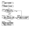
- the control unit 1 operates as follows.
- the duty setting unit 14 of the video signal processing unit 10 included in the control unit 1 acquires measured temperature data (temperature data) from the panel thermistor 83. Then, the duty setting unit 14 acquires one of the memory data DM stored in the memory 17.
- the memory data DM is a data table (lookup table) of the response speed Vr of the liquid crystal molecules 61M depending on the temperature of the liquid crystal 61 (liquid crystal temperature Tp). That is, the duty setting unit 14 obtains the response speed Vr by associating the temperature data of the panel thermistor 83 with the liquid crystal temperature Tp of the data table.
- the duty setting unit 14 sets the duty of the PWM dimming signal corresponding to the acquired response speed Vr.
- the method of setting the duty is not particularly limited.
- a duty data table depending on the response speed Vr is stored in the memory 17, and the duty setting unit 14 sets the duty by using the data table. It is good to set.
- FIG. 23A shows a PWM dimming signal with a duty of 100% and a PWM dimming signal with a duty of 50% (note that the PWM dimming signal is 120 Hz, and the interval between dotted lines represents one frame period).
- the luminance resulting from such a PWM dimming signal can be roughly compared with the size of the hatched area that is written directly below the graph of each PWM dimming signal. In short, a rough luminance comparison is possible in the area obtained by multiplying the lighting period of the PWM dimming signal and the current value.
- the current value AM is the same. Therefore, in one cycle of the PWM dimming signal, if the lighting period when the duty is 100% is W100, the current value is AM100, the lighting period when the duty is 50% is W50, and the current value is AM50, the luminance comparison is Duty100. % Is brighter than Duty 50% (W100 ⁇ AM100> W50 ⁇ AM50).
- the duty of the PWM dimming signal changes corresponding to the response speed Vr
- a luminance difference is generated according to the duty, which causes image quality deterioration. Therefore, the current value of the PWM dimming signal changes according to the duty.
- the luminance at 100% Duty in FIG. 23A is used as a reference, the luminance is discussed as shown in FIG. 23B for Duty 80%, FIG. 23C for Duty 60%, and FIG. 23D for Duty 50%.
- the current value setting unit 15 of the arithmetic processing unit 13 calculates the integrated amount of light emission in one cycle period of the PWM dimming signal and the integrated amount of light emission in 100% duty in the time corresponding to the one cycle period.
- the current value AM of the PWM dimming signal when driving with a duty other than 100% is changed so as to match. In this case, even if the duty is changed according to the response speed Vr of the liquid crystal molecules 61M, the luminance does not change due to the duty (in short, the liquid crystal display device 90 is Duty can be changed while maintaining high brightness).
- the method of setting the current value AM by the current value setting unit 15 is not particularly limited. For example, after the current value setting unit 15 receives a duty data signal, the current value AM is subjected to calculation processing by itself. Or a data table of the current value AM depending on the duty may be stored by itself, and the current value AM may be set using the data table.
- the liquid crystal display device 90 is equipped with various functions in order to improve the image quality.
- various functions for example, there are an FRC processing function and a viewing mode setting function for changing the image display format according to the viewer's preference.
- an environment-friendly function that adjusts the brightness of the liquid crystal display panel 60 according to the brightness of the environment where the liquid crystal display device 90 is placed can be cited.
- a video signal corresponding function for adjusting the brightness of the liquid crystal display panel 60 in accordance with the luminance of the video signal (average signal level ASL or the like) can also be mentioned.
- the duty setting unit 14 of the arithmetic processing unit 13 acquires the temperature data of the panel thermistor 83 (STEP 1) and acquires the response speed Vr of the liquid crystal molecules 61M (STEP 2), as shown in the flowchart of FIG.
- the duty setting unit 14 determines the response speed Vr (response speed data). Specifically, the duty setting unit 14 determines whether or not the duty setting should be changed according to the presence or absence of various function operations (STEP 3). For example, if the response speed Vr is excessively low and multiple contours are generated if the duty is not set high regardless of whether or not various functions are operated (NO in STEP 3), the duty setting unit 14 Considering the response speed Vr corresponding to the temperature Tp, the duty is set to 100%, for example (STEP 4). In this way, the occurrence of multiple contours is prevented.
- the duty setting unit 14 determines that it is desirable to change the setting of the duty due to the operation of various functions (YES in STEP 4).
- the duty setting unit 14 considers various functions. And set Duty. This is because the image quality can be improved with certainty.
- the duty setting unit 14 determines whether or not there is an FRC process (STEP 5). Specifically, as shown in FIG. 2, the duty setting unit 14 receives a signal (ON / OFF signal) indicating the presence / absence of FRC processing from the FRC processing unit 21 of the LCD controller 20. When the FRC process is not performed (NO in STEP 5), that is, the number of frames of the video signal is smaller than the predetermined number, the duty setting unit 14 sets the response speed Vr corresponding to the liquid crystal temperature Tp. A duty similar to the considered duty is set, that is, a relatively high duty is set (STEP 4).
- the duty setting unit 14 determines whether or not the immediately preceding duty needs to be changed according to the FRC process (STEP 6). This is because the previous duty, that is, the duty set in STEP 4 may not be different from the duty when the FRC process is performed.
- the duty setting unit 14 determines that the immediately preceding duty needs to be changed (YES in STEP 6)
- the duty is set in consideration of the response speed Vr and the FRC process according to the liquid crystal temperature Tp ( (Step 7). For example, when there is an FRC process, the duty setting unit 14 decreases the duty (note that the tendency of the duty depending on the presence or absence of the FRC process is shown in the table of FIG. 26). In this way, the sharpness of the image quality is improved.
- the duty setting unit 14 determines that the previous duty change is not required (NO in STEP 6)
- the duty setting unit 14 sets the duty considering only the response speed Vr according to the liquid crystal temperature Tp (STEP 4). ).
- control unit 1 shown in FIG. 1 includes an FRC processing unit 21 that performs frame rate control processing, and the control unit 1 (specifically, the duty setting unit 14) performs FRC processing by the FRC processing unit 21.
- the duty is changed according to the presence or absence (the current value AM may be changed according to the change of the duty). Note that the duty when there is an FRC process is lower than the duty when there is no FRC process (see FIG. 26).
- the duty setting unit 14 may make a determination according to the setting of the viewing mode. Specifically, as shown in FIG. 2, the duty setting unit 14 is a mode type signal MD indicating the type of viewing mode from the viewing mode setting unit 16 of the video signal processing unit 10, for example, a relatively high moving image level. A signal indicating that the mode is the sport mode is received.
- MD mode type signal
- a signal indicating that the mode is the sport mode is received.
- the duty setting unit 14 determines whether or not the previous duty needs to be changed according to the moving image level (STEP 15). This is because the last duty, that is, the duty set in STEP 4, may not be different from the duty when the moving image level is high.
- the duty setting unit 14 determines that the previous duty needs to be changed (in the case of YES in STEP 15), the duty is set in consideration of the response speed Vr and the moving image level according to the liquid crystal temperature Tp (STEP 16). For example, when the sport mode is set, the duty setting unit 14 decreases the duty (note that the tendency of the duty according to the magnitude relationship of the moving image level is shown in the table of FIG. 28). In this way, the sharpness of the image quality is improved.
- the duty setting unit 14 determines that it is not necessary to change the immediately preceding duty (in the case of NO in STEP 15), it sets the duty considering only the response speed Vr corresponding to the liquid crystal temperature Tp (STEP 4). ).
- control unit 1 shown in FIG. 1 includes a viewing mode setting unit 16 that switches the viewing mode of the liquid crystal display panel 60.
- the control unit 1 (details)
- the duty setting unit 14) changes the duty according to the selected viewing mode (the current value AM may be changed according to the change of the duty).
- the viewing mode setting unit 16 sets the high video level viewing mode and the low video level viewing mode according to the video level of the video data.
- the duty is changed for each selected viewing mode so as to be inversely related to the height relationship (magnitude relationship) of the moving image levels in the plurality of viewing modes (see FIG. 28).
- the duty setting unit 14 may make a determination according to the setting of viewing modes with different contrast ratios. Specifically, the duty setting unit 14 receives a signal mode type signal MD indicating the type of viewing mode from the viewing mode setting unit 16, for example, a signal indicating a dynamic mode with a relatively high contrast ratio.
- the duty setting unit 14 determines whether or not it is necessary to change the immediately preceding duty according to the contrast ratio (STEP 25). This is because the previous duty, that is, the duty set in STEP 4 may not be different from the duty when the contrast ratio is high.
- the duty setting unit 14 determines that the previous duty needs to be changed (in the case of YES in STEP 25), the duty is set in consideration of the response speed Vr and the contrast ratio according to the liquid crystal temperature Tp (STEP 26). For example, when the dynamic mode is set, the duty setting unit 14 decreases the duty (note that the tendency of the duty depending on the magnitude relationship of the contrast ratio is shown in the table of FIG. 30). In this way, the sharpness of the image quality is improved.
- the duty setting unit 14 determines that it is not necessary to change the immediately preceding duty (in the case of NO in STEP 25), it sets the duty taking into consideration only the response speed Vr according to the liquid crystal temperature Tp (STEP 4). ).
- the viewing mode setting unit 16 sets the high contrast level viewing mode and the low contrast level viewing mode in accordance with the contrast level of the video data, the contrast level of the plurality of viewing modes (magnitude relationship). ), The duty is changed for each selected viewing mode (see FIG. 30).
- the duty setting unit 14 may set the duty by a combination of various modes.
- the duty setting unit 14 is a mode type signal MD indicating the type of viewing mode from the viewing mode setting unit 16, for example, a sports mode with a relatively high moving image level and a dynamic mode with a relatively high contrast ratio. A signal indicating that there is a signal is received.
- the duty setting unit 14 determines whether or not the previous duty needs to be changed, for example, according to the moving image level (STEP 15). When it is determined that the previous duty change is not required (NO in STEP 15), the duty setting unit 14 sets the duty considering only the response speed Vr according to the liquid crystal temperature Tp (STEP 4). .
- the duty setting unit 14 determines whether or not the immediately preceding duty needs to be changed (YES in STEP 15), it further determines whether or not the immediately preceding duty needs to be changed according to the contrast ratio. (STEP 36).
- the duty setting unit 14 determines that the previous duty needs to be changed (YES in STEP 36)
- the duty setting unit 14 determines that the previous duty change is not required (NO in STEP 36)
- the duty setting unit sets the response speed Vr corresponding to the liquid crystal temperature Tp and the video level. (STEP 16).
- the moving image level is considered first, and the contrast ratio is considered later, but this order may be different.
- the duty setting unit 14 may make a determination according to the brightness of the environment where the liquid crystal molecules 61M are placed. Specifically, the duty setting unit 14 receives the illuminance data of the environmental illuminance sensor 84 as shown in FIG. 2 (in short, the duty setting unit 14 determines the brightness of the installation location of the liquid crystal display device 90). The material is the measured illuminance of the environmental illuminance sensor 84 that measures external illuminance).
- the duty setting unit 14 determines whether or not the previous duty needs to be changed according to the illuminance data (STEP 45). This is because the previous duty, that is, the duty set in STEP 4, may not be different from the duty when the illuminance data is high (in other words, when the environment is relatively bright).
- the duty setting unit 14 determines that the immediately preceding duty needs to be changed (in the case of YES in STEP 45), the duty is set in consideration of the response speed Vr and the illuminance data according to the liquid crystal temperature Tp ( (STEP 46). For example, when the liquid crystal display device 90 is installed in a relatively bright environment, the duty setting unit 14 reduces the duty (note that the tendency of the duty depending on the magnitude relation of the illuminance data is shown in FIG. To show). In this way, the sharpness of the image quality is improved.
- the duty setting unit 14 determines that it is not necessary to change the immediately preceding duty (in the case of NO in STEP 45), it sets the duty considering only the response speed Vr according to the liquid crystal temperature Tp (STEP 4). ).
- control unit 1 shown in FIG. 1 acquires external illuminance data, and changes the duty according to the illuminance data (note that the current value AM is changed in accordance with the change in the duty. May be good). Note that the duty is changed for each illuminance data range so as to be opposite to the magnitude relationship of the data values for each of the plurality of illuminance data ranges (see FIG. 33).
- the duty setting unit 14 may make a determination according to the luminance or the like (average signal level ASL or the like) of the video signal. Specifically, the duty setting unit 14 receives the histogram data HGM of the histogram processing unit 12 via the arithmetic processing unit 13 as shown in FIG. Then, using this histogram data HGM, Duty is changed.
- the response speed Vr of the liquid crystal molecules 61M is dependent on the temperature, but is also dependent on the change between gradations.
- FIGS. show the response time when the liquid crystal molecules 61M to be changed in gradation from the 0th gradation to the other gradation are tilted.
- FIG. 34 shows a relatively high temperature liquid crystal temperature Tp
- FIG. 35 shows a relatively low temperature liquid crystal. It corresponds to the temperature Tp (note that the liquid crystal 61 is in the MVA mode).
- the response speed Vr of the liquid crystal molecules 61M is relatively low.
- the duty ratio of the PWM dimming signal is set low for such liquid crystal molecules 61M, multiple contours may occur as shown in FIG. Therefore, in such a case, the duty of the PWM dimming signal is set high to prevent multiple contours.
- the duty of the PWM dimming signal should be set low in order to improve the sharpness of image quality, etc. (In short, the effect of black insertion of the PWM dimming signal appears remarkably) ).
- the duty setting unit 14 includes an arithmetic processing unit.
- the histogram data HGM is acquired from 13 (STEP 55).
- the duty setting unit 14 acquires a gradation threshold (gradation threshold data) set in accordance with the liquid crystal temperature Tp stored in the memory 17 in advance, and whether or not a specific gradation range can be set. (STEP 56).
- the difference TW [MVA, HOT] is relatively small as shown in FIG. Then, the difference in response time with gradation change under the high temperature liquid crystal temperature Tp is smaller than the difference in response time with gradation change under the low temperature liquid crystal temperature Tp.
- the duty setting unit 14 sets the duty considering only the response speed Vr according to the liquid crystal temperature Tp (STEP 4).
- the duty setting unit 14 displays the histogram data. It tries to change Duty using HGM (in the case of YES of STEP56). Specifically, the duty setting unit 14 is configured to change the duty from a histogram threshold set according to the histogram data HGM and the liquid crystal temperature Tp stored in the memory 17. An adjustment range is set (STEP 57). For example, when the liquid crystal temperature Tp is low (for example, about 20 ° C.) in the MVA mode liquid crystal 61, the specific gradation range is set from the 0th gradation to the 128th gradation as shown in FIG. (In short, the gradation range of 0 to 128 of the entire gradation range of 0 to 255 is the specific gradation range).
- the duty setting unit 14 acquires the occupancy ratio in the image (one frame image) in the specific gradation range from the histogram data HGM, and the occupancy ratio and the specific gradation range stored in the memory 17.
- a threshold relating to the occupation ratio (occupancy threshold; for example, 50%) is compared (STEP 58).
- the duty setting unit 14 sets a higher duty, for example 100%, taking into account only the response speed Vr according to the liquid crystal temperature Tp (STEP 4).
- the duty setting unit 14 determines whether or not it is necessary to change the immediately preceding duty according to the occupation ratio (STEP 59). This is because the last duty, that is, the duty set in STEP 4, may not be different from the duty when the occupation ratio is high (in the case of a low gradation image).
- the duty setting unit 14 determines that the immediately preceding duty needs to be changed (YES in STEP 59)
- the response speed Vr and gradation in short, the histogram data HGM corresponding to the liquid crystal temperature Tp Is set in consideration of the above (STEP 60).
- the duty setting unit 14 in the MVA mode liquid crystal display device 90 sets a low duty, for example, 50% (note that the occupation ratio is small or large).
- the tendency of Duty depending on the relationship is shown in the table of FIG. 37). In this way, the sharpness of the image quality is improved.
- the duty setting unit 14 determines that it is not necessary to change the immediately preceding duty (in the case of NO in STEP 59), it sets the duty considering only the response speed Vr corresponding to the liquid crystal temperature Tp (STEP 4). ).
- the histogram unit 18 generates the histogram data HGM indicating the frequency distribution with respect to the gradation by making the video signal into a histogram. Further, the control unit 1 classifies all the gradations of the histogram data HGM, and determines whether the occupation ratio in at least one specific gradation range of the divided gradation ranges exceeds or is less than the occupation ratio threshold. to decide.
- the duty when exceeding the occupancy threshold is made higher than the duty when it is less than or equal to the occupancy threshold, while the duty when lower than the occupancy threshold is made lower than the duty when exceeding the occupancy threshold (Note that the current value AM may be changed according to the change in Duty).
- the above-mentioned specific gradation range from the 0th gradation to the 128th gradation and the occupation ratio of the specific gradation range are occupied.
- the rate threshold value of 50% is merely an example (a plurality of specific gradation ranges may be used).
- the temperature data of the panel thermistor 83 that is, according to the liquid crystal temperature Tp, at least one of the specific gradation range and the occupation ratio threshold value may change. Therefore, for example, even in the case of the liquid crystal temperature Tp as shown in FIG. 34, a specific gradation range may be set.
- FIGS. 38 and 39 in the IPS mode liquid crystal 61, the maximum and minimum values of the response time are the same when the liquid crystal temperature Tp is high (see FIG. 38) and low (see FIG. 39).
- the difference TW is relatively small (Note that FIGS. 38 and 39 show the response time of tilting of the liquid crystal molecules 61M that attempt to change the gradation from the 0th gradation to the other gradation, as in FIGS. 34 and 35. ).
- FIG. 38 and FIG. 39 are flat graph lines as compared with FIG. 35, for example.
- the difference in response time with the gradation change under the liquid crystal temperature Tp at high and low temperatures is relatively small. Therefore, a specific gradation range in the image may be set, and the duty may not be changed according to the occupation ratio of the specific range. However, depending on the case, the duty may be changed in accordance with the video signal support function.
- the FRC processing function, the viewing mode setting function, the environment support function, and the video signal support function described above may operate in various combinations. Even in such a case, the duty may be changed.
- the duty setting unit 14 sets the FRC as shown in the flowchart of FIG. The presence or absence of processing may be determined (STEP 61).
- the duty setting unit 14 sets the duty considering the response speed Vr and the gradation according to the liquid crystal temperature Tp in STEP 60 (STEP 60). .
- the duty setting unit 14 determines whether or not the immediately preceding duty needs to be changed according to the FRC process (STEP 62).
- the duty setting unit 14 determines that the previous duty change is not required (NO in STEP 62)
- the duty is set in consideration of the response speed Vr and gradation according to the liquid crystal temperature Tp in STEP 60. (STEP 60).
- the duty setting unit 14 determines that the previous duty needs to be changed (in the case of YES in STEP 62), the previous duty is required to be changed according to the viewing mode (for example, the video level). (STEP 63).
- the duty setting unit 14 determines that the previous duty change is not required (in the case of NO in STEP 63)
- the duty considering the response speed Vr, gradation, and FRC processing according to the liquid crystal temperature Tp is set. Set (STEP 64).
- the duty setting unit 14 determines whether or not the previous duty change is required according to the illuminance data (STEP 65). If the duty setting unit 14 determines that the previous duty change is not required (NO in STEP 65), the response speed Vr, gradation, FRC processing, and viewing mode corresponding to the liquid crystal temperature Tp are considered. The set duty is set (STEP 66).
- the duty setting unit 14 changes the duty even when the FRC processing function, the viewing mode setting function, the environment support function, and the video signal support function operate in combination.
- the current value AM may be changed in accordance with the change in Duty).
- the order of the functions is not limited to the order of the video signal corresponding function, the FRC processing function, the viewing mode setting function, and the environment corresponding function as shown in the flowcharts of FIGS. 36 and 40. It doesn't matter.
- the number of function combinations is not limited to four, ie, a video signal support function, an FRC processing function, a viewing mode setting function, and an environment support function, and may be three or less, as long as there are other various functions. There may be five or more.
- FIGS. 41 to 44 are the same as FIGS. 14 to 17 (therefore, the scroll speed is 32 pixels / 16.7 ms).
- 41 shows a case where the response speed Vr is relatively slow and has a duty of 70%
- FIG. 42 shows a case where the response speed Vr is relatively slow and has a duty of 30%.
- FIG. 43 shows a case where the response speed Vr is relatively fast and has a duty of 70%
- FIG. 44 shows a case where the response speed Vr is relatively fast and has a duty of 30%.
- FIG. 41 is compared with FIG. 14, the step of the graph line not shown in FIG. 14 is confirmed in FIG. That is, in FIG. 41, pixels with different degrees of change in integral luminance (in short, the slope of the graph line in FIG. 14) are continuous. However, as shown in FIG. 15, the difference in the degree of change in the integrated luminance is not large. Therefore, multiple contours do not occur.
- the response speed Vr of the liquid crystal molecules 61M when the response speed Vr of the liquid crystal molecules 61M is relatively high, the effect of black insertion becomes more noticeable as the duty is lower (for example, the sharpness of image quality is improved). . That is, when the response speed Vr of the liquid crystal molecules 61M is relatively fast, the duty is preferably 50% or less, and preferably 30% or less.
- the duty of the PWM dimming signal or the duty and the current value are variously changed. Even if it is other than such control, the image quality can be improved.
- the image quality can be improved by variously changing the drive frequency FQ [PWM] of the PWM dimming signal.
- a liquid crystal display device 90 that performs such control will be described below.
- FIGS. 46 and 47 are block diagrams showing various members relating to the liquid crystal display device 90 (note that FIGS. 46 and 47 are block diagrams in which a part of FIG. 45 is extracted and shown in detail).
- the drive frequency of the LED 71 (the PWM dimming signal) from the LED controller 30 to the LED driver 85 is described.
- a setting signal CS for setting the driving frequency FQ [PWM]) is transmitted (see FIGS. 45 and 47).
- HGM histogram data HGM (HGM [S] / HGM [L]) of the arithmetic processing unit 13, various data (memory data DM) stored in the memory 17, and viewing mode setting
- MD histogram data
- DM memory data
- the mode type signal MD indicating the type of the viewing mode of the unit 16, the temperature data of the panel thermistor 83, and the illuminance data of the environmental illuminance sensor 84 are not transmitted to the duty setting unit 14, but the control unit 1 (specifically, To the LED controller 30). Further, a signal (ON / OFF signal) indicating whether or not the FRC processing is performed from the FRC processing unit 21 is transmitted to the LED controller 30.
- the histogram data HGM, memory data DM, mode type signal MD, temperature data, illuminance data, and ON / OFF signal are included in the LED controller 30 and transmitted to the drive frequency variable unit 41.
- the drive frequency variable unit 41 switches the drive frequency FQ [PWM] according to the liquid crystal temperature Tp.
- the duty setting unit 14 controls to increase the duty.
- the drive frequency variable unit 41 changes the drive frequency FQ [PWM] of the PWM dimming signal to a frequency higher than 120 Hz, for example, 480 Hz. Then, as in FIG. 48A corresponding to FIG. 15 (FIG. 13B), even at a drive frequency FQ [PWM] of 480 Hz, continuously in a response process time zone CW with a certain interval, Light is supplied to the liquid crystal display panel 60 (see FIG. 48B). The luminance value of the supplied light is lower than the maximum luminance value.
- the drive frequency FQ [PWM] is higher when the number of high periods of the PWM dimming signal is the drive frequency FQ [PWM] 480 Hz in the response period CW. Increased compared to 120 Hz.
- the integrated luminance corresponding to the vicinity of the boundary is as shown in the graph of FIG. 49 (the scroll speed is 32 pixels). /16.7ms). That is, pixels that receive light that is insufficient to form a complete white image are generated near the boundary.
- Such a continuous pixel range PA [50L-480] of pixels is recognized as a problematic pixel (see image diagram). More specifically, switching from a black image to a white image is not performed at high speed, and pixels with different degrees of change in integrated luminance (mainly, the slope of the graph in FIG. 49) are included in the pixel range PA [50L-480]. It is.
- the number of high periods of the PWM dimming signal in the response process time zone CW is large. Then, the number of steps in the graph line in FIG. 49 due to the degree of change in the integrated luminance becomes larger than the number of steps in the graph line in FIG. In this case, the graph line in FIG. 49 becomes pseudo like the graph line in FIG. Therefore, in the case of FIG. 49, only an afterimage occurs, not a multiple contour. That is, the multiple contour that causes the worst image quality degradation is prevented.
- the LED 71 when the response speed Vr of the liquid crystal molecules 61M is relatively fast, the LED 71 is driven at a relatively low drive frequency FQ [PWM], while the response speed of the liquid crystal molecules 61M. When Vr is relatively slow, the LED 71 may be driven at a relatively high drive frequency FQ [PWM].
- the threshold value (response speed data threshold value) that determines whether the response speed Vr is fast or slow is arbitrarily set. Therefore, when a table is created with the same arrows as in FIGS. 20 and 21, it is as shown in FIGS.
- the response speed Vr of the liquid crystal molecules 61M is divided in stages, and the image quality can be improved in accordance with the stages.
- the drive frequency FQ [PWM] is changed for each range of the response speed Vr so as to be inversely related to the magnitude relation regarding the range of the plurality of response speeds Vr.
- the response speed Vr is a small value Vr1
- the drive frequency FQ [PWM] is a large value FQ [PWM] 2
- the response speed Vr is large.
- the drive frequency FQ [PWM] should be the drive frequency FQ [PWM] 1 which is a small value (Note that the magnitude relationship between the data values of the response speed Vr is Vr1 ⁇ Vr2, and the drive The magnitude relationship between the data values of the frequency FQ [PWM] is FQ [PWM] 1 ⁇ FQ [PWM] 2.
- one of the fluctuation factors of the response speed Vr in the liquid crystal molecules 61M is the temperature Tp of the liquid crystal molecules 61M. Therefore, when the magnitude relationship between the data values of the temperature Tp is written together in the table of FIG. 52, a table as shown in FIG. 53 is obtained.
- the control unit 1 operates as follows.
- the drive frequency variable unit 41 of the LED controller 30 included in the control unit 1 acquires measured temperature data (temperature data) from the panel thermistor 83. Then, the drive frequency variable unit 41 acquires one of the memory data DM stored in the memory 17.
- the memory data DM is a data table of the response speed Vr of the liquid crystal molecules 61M depending on the temperature of the liquid crystal 61 (liquid crystal temperature Tp). That is, the drive frequency variable unit 41 obtains the response speed Vr by associating the temperature data of the panel thermistor 83 with the liquid crystal temperature Tp of the data table.
- the drive frequency variable part 41 sets the drive frequency FQ [PWM] of the PWM dimming signal corresponding to the acquired response speed Vr.
- the method of setting the drive frequency FQ [PWM] is not particularly limited. For example, after the drive frequency variable unit 41 obtains the response speed Vr, the drive frequency FQ [PWM] is processed by itself to generate the setting signal CS and drive.
- the frequency FQ [PWM] may be set, or the data table of the drive frequency FQ [PWM] depending on the response speed Vr is stored by itself, the setting signal CS is generated using the data table, and the drive frequency FQ [PWM] may be set.
- the liquid crystal display device 90 also includes a video signal support function, an FRC processing function, a viewing mode setting function, and an environment support function.
- the drive frequency FQ [PWM] of the PWM dimming signal changes according to these various functions.
- the drive frequency variable unit 41 of the LED controller 30 acquires the temperature data of the panel thermistor 83 (STEP 101), and acquires the response speed Vr of the liquid crystal molecules 61M (STEP 102).
- the drive frequency variable unit 41 determines the response speed Vr (response speed data). Specifically, the drive frequency variable unit 41 determines whether or not the setting of the drive frequency FQ [PWM] should be changed according to whether or not various functions are operated (STEP 103). For example, when the response speed Vr is fast and the drive frequency FQ [PWM] is set low regardless of whether various functions are operated, the black insertion effect can be obtained (NO in STEP 103), and the drive frequency can be varied. The unit 41 sets the drive frequency FQ [PWM] to 120 Hz, for example, in consideration of the response speed Vr corresponding to the liquid crystal temperature Tp (STEP 104). In this way, the moving image performance and the like of image quality are improved.
- the drive frequency variable unit 41 determines that it is desirable to change the setting of the drive frequency FQ [PWM] due to the operation of various functions (YES in STEP 104), the drive frequency variable unit 41 sets the drive frequency FQ [PWM] in consideration of various functions. This is because the image quality can be improved with certainty.
- the drive frequency variable unit 41 may make a determination according to the luminance or the like (average signal level ASL or the like) of the video signal. Normally, when an occupancy rate in a low gradation range is high in an image of one frame (in the case of a relatively low gradation image, for example), the lighting time of the LED 71 is set short (in short, the duty is Is small). On the other hand, when the occupancy rate of the low gradation range is low (in the case of a relatively high gradation image), the lighting time of the LED 71 is set to be long (in short, the duty is large).
- the liquid crystal molecules 61M in the response process time zone CW are conspicuous in the light from the LED 71 (that is, the backlight light BL), resulting in multiple contours and afterimages. obtain.
- the drive frequency FQ [PWM] is changed according to the occupation ratio of the gradation range of the image.
- the drive frequency varying unit 41 acquires the histogram data HGM from the arithmetic processing unit 13 (STEP 105).
- the drive frequency variable unit 41 acquires a gradation threshold (gradation threshold data) set according to the liquid crystal temperature Tp stored in the memory 17 in advance, and can a specific gradation range be set? It is determined whether or not (STEP 106).
- the drive frequency variable unit 41 sets the drive frequency FQ [PWM] considering only the response speed Vr corresponding to the liquid crystal temperature Tp (STEP 104).
- the drive frequency variable unit 41 uses the histogram data HGM, The drive frequency FQ [PWM] is to be changed (in the case of STEP 106 YES).
- the drive frequency variable unit 41 should change the drive frequency FQ [PWM] from the histogram data HGM and the gradation threshold value set according to the liquid crystal temperature Tp stored in the memory 17.
- a specific gradation range is set (STEP 107). For example, when the liquid crystal temperature Tp is low (for example, about 20 ° C.) in the MVA mode liquid crystal 61, the specific gradation range is set from the 0th gradation to the 128th gradation as shown in FIG. Is done.
- the drive frequency variable unit 41 acquires the occupancy ratio in the image (one frame image) in the specific gradation range, and the threshold value regarding the occupancy ratio and the occupancy ratio of the specific gradation range stored in the memory 17. (Occupancy threshold: 50%, for example) is compared (STEP 108).
- the occupancy rate is not less than or equal to the threshold value (ie, the occupancy rate exceeds the occupancy rate threshold value; in the case of NO in STEP 108), for example, specific gradations from the 0th gradation to the 128th gradation It can be said that it is a low gradation image containing a large amount of range. Then, the duty of the PWM dimming signal for the low gradation image is smaller than the duty of the PWM dimming signal for the high gradation image.
- the drive frequency variable unit 41 sets the drive frequency FQ [PWM] taking into account only the response speed Vr according to the liquid crystal temperature Tp to 120 Hz, for example (STEP 104).
- the drive frequency varying unit 41 determines whether or not it is necessary to change the immediately preceding drive frequency FQ [PWM] according to the occupation ratio (STEP 109). This is because the drive frequency FQ [PWM] when the immediately preceding drive frequency FQ [PWM], that is, the drive frequency FQ [PWM] set in STEP 104 has a high occupancy rate (in the case of a low gradation image). This is because it may not change.
- the drive frequency variable unit 41 determines that the previous drive frequency FQ [PWM] needs to be changed (in the case of YES in STEP 109)
- the response speed Vr corresponding to the liquid crystal temperature Tp and the gradation (in short) , Histogram data HGM) is set in consideration of the driving frequency FQ [PWM] (STEP 110).
- the drive frequency variable unit 41 in the MVA mode liquid crystal display device 90 sets the drive frequency FQ [PWM] to, for example, 480 Hz (note that 55 shows the tendency of the magnitude of the drive frequency variable unit 41 according to the magnitude relationship of the occupation ratio). In such a case, the occurrence of multiple contours is prevented even if the duty is higher than that of the low gradation image due to the high gradation image.
- the histogram unit 18 generates the histogram data HGM indicating the frequency distribution with respect to the gradation by making the video signal into a histogram. Then, the control unit 1 classifies all the gradations of the histogram data HGM, and determines whether the occupation ratio in at least one specific gradation range among the divided gradation ranges exceeds or is less than the occupation ratio threshold. to decide.
- the drive frequency FQ [PWM] in the case of exceeding the occupancy threshold is set lower than the drive frequency in the case of the occupancy threshold or less, while the drive frequency in the case of the occupancy threshold or less exceeds the occupancy threshold. Higher than the drive frequency in the case.
- the above-mentioned specific gradation range from the 0th gradation to the 128th gradation and the occupation ratio of the specific gradation range are occupied.
- the rate threshold value 50% is only an example as in the first embodiment (the specific gradation range may be plural).
- the above-described drive frequencies FQ [PWM] of 480 Hz and 120 Hz are merely examples.
- the drive frequency FQ [PWM] may not be changed. However, in some cases, the drive frequency FQ [PWM] may be changed in accordance with the video signal support function.
- the drive frequency variable unit 41 may determine whether or not the FRC process is performed (STEP 105). Specifically, the drive frequency variable unit 41 receives a signal (ON / OFF signal) indicating whether or not the FRC processing is performed from the FRC processing unit 21 of the LCD controller 20.
- the drive frequency variable unit 41 sets a drive frequency FQ [PWM] similar to the drive frequency FQ [PWM] considering the response speed Vr corresponding to the liquid crystal temperature Tp (STEP 104). .
- the drive frequency variable unit 41 determines whether or not it is necessary to change the previous drive frequency FQ [PWM] according to the FRC process. (STEP 126). This is because the immediately preceding drive frequency FQ [PWM], that is, the drive frequency FQ [PWM] set in STEP 104 may not be different from the drive frequency FQ [PWM] when the FRC process is performed.
- the drive frequency variable unit 41 determines that the previous drive frequency FQ [PWM] needs to be changed (YES in STEP 126), the response speed Vr corresponding to the liquid crystal temperature Tp and the FRC process are considered.
- the drive frequency FQ [PWM] thus set is set (STEP 127). For example, when there is no FRC process, the drive frequency variable unit 41 improves the drive frequency FQ [PWM] (Note that the tendency of the drive frequency FQ [PWM] depending on the presence or absence of the FRC process is shown in the table of FIG. Show). In this way, the occurrence of multiple contours is prevented.
- control unit 1 shown in FIG. 1 includes an FRC processing unit 21 that performs a frame rate control process, and the control unit 1 (specifically, the drive frequency variable unit 41) includes the presence or absence of the FRC processing unit 21 FRC processing.
- the drive frequency FQ [PWM] is changed. Note that the drive frequency FQ [PWM] when the FRC process is present is lower than the drive frequency FQ [PWM] when the FRC process is absent (see FIG. 57).
- the drive frequency variable unit 41 may make a determination according to the setting of the viewing mode.
- the drive frequency variable unit 41 is a mode type signal MD indicating the type of viewing mode from the viewing mode setting unit 16 of the video signal processing unit 10, for example, a natural mode with a relatively low moving image level. A signal indicating is received.
- the drive frequency variable unit 41 determines whether or not the previous drive frequency FQ [PWM] needs to be changed according to the moving image level. Judgment is made (STEP 135). This is because the immediately preceding drive frequency FQ [PWM], that is, the drive frequency FQ [PWM] set in STEP 104 may not be different from the drive frequency FQ [PWM] when the moving image level is low.
- the drive frequency variable unit 41 determines that the previous drive frequency FQ [PWM] needs to be changed (YES in STEP 135), the response speed Vr corresponding to the liquid crystal temperature Tp and the moving image level are considered.
- the drive frequency FQ [PWM] thus set is set (STEP 136).
- the drive frequency variable unit 41 improves the drive frequency FQ [PWM] (note that the drive frequency FQ [PWM] tends to be large or small according to the magnitude relationship of the moving image level). 59). In this way, the occurrence of multiple contours is prevented.
- the drive frequency variable unit 41 determines that it is not necessary to change the immediately preceding drive frequency FQ [PWM] (NO in STEP 135), only the response speed Vr corresponding to the liquid crystal temperature Tp is considered.
- the drive frequency FQ [PWM] is set (STEP 104).
- control unit 1 includes the viewing mode setting unit 16 that switches the viewing mode of the liquid crystal display panel 60.
- the control unit 1 (specifically, the drive frequency is variable).
- the unit 41) changes the drive frequency FQ [PWM] in accordance with the selected viewing mode.
- the viewing mode setting unit 16 determines whether the high moving image level viewing mode and the low moving image level viewing mode are in accordance with the moving image level of the video data. Is set, the drive frequency FQ [PWM] is changed for each selected viewing mode so as to be inversely related to the level relationship (magnitude relationship) of the moving image levels in a plurality of viewing modes (see FIG. 59). ).
- the drive frequency variable unit 41 may make a determination according to setting of viewing modes with different contrast ratios. Specifically, the drive frequency variable unit 41 receives a signal mode type signal MD indicating the type of viewing mode from the viewing mode setting unit 16, for example, a signal indicating that the cinema mode is a relatively low contrast ratio. .
- the drive frequency variable unit 41 determines whether or not the previous drive frequency variable unit 41 needs to be changed according to the contrast ratio. (STEP145). This is because the immediately preceding drive frequency FQ [PWM], that is, the drive frequency FQ [PWM] set in STEP 104 may not be different from the drive frequency FQ [PWM] when the contrast ratio is low.
- the drive frequency variable unit 41 determines that the previous drive frequency FQ [PWM] needs to be changed (YES in STEP 145), the response speed Vr and the contrast ratio corresponding to the liquid crystal temperature Tp are considered.
- the drive frequency FQ [PWM] thus set is set (STEP 146). For example, when the cinema mode is set, the drive frequency varying unit 41 improves the drive frequency FQ [PWM] (note that the drive frequency FQ [PWM] tends to be larger or smaller depending on the contrast ratio). 61 table). In this way, the occurrence of multiple contours is prevented.
- the viewing mode setting unit 16 sets the high contrast level viewing mode and the low contrast level viewing mode in accordance with the contrast level of the video data, the contrast level of the plurality of viewing modes (magnitude relationship).
- the driving frequency FQ [PWM] is changed for each selected viewing mode so as to be in an inverse relationship with ().
- the driving frequency variable unit 41 may set the driving frequency FQ [PWM] by combining various modes.
- the drive frequency variable unit 41 is a mode type signal MD indicating the type of viewing mode from the viewing mode setting unit 16, for example, a natural mode with a relatively low moving image level and a cinema mode with a relatively low contrast ratio. A signal indicating that is received.
- the drive frequency variable unit 41 determines whether or not it is necessary to change the immediately preceding drive frequency FQ [PWM] according to the moving image level, for example. Judgment is made (STEP 135). When it is determined that it is not necessary to change the immediately preceding drive frequency FQ [PWM] (NO in STEP 135), the drive frequency variable unit 41 drives only considering the response speed Vr according to the liquid crystal temperature Tp. The frequency FQ [PWM] is set (STEP 104).
- the drive frequency variable unit 41 determines that the previous drive frequency FQ [PWM] needs to be changed (YES in STEP 135)
- the previous drive frequency FQ [PWM] is further determined according to the contrast ratio. ] Is determined (STEP 156).
- the drive frequency variable unit 41 determines that the previous drive frequency FQ [PWM] needs to be changed (YES in STEP 156)
- the response speed Vr, the moving image level, and the contrast ratio according to the liquid crystal temperature Tp is set in consideration of the above (STEP 157).
- the drive frequency variable unit 41 determines that the previous drive frequency FQ [PWM] does not need to be changed (NO in STEP 156)
- the response speed Vr and the moving image level corresponding to the liquid crystal temperature Tp are determined.
- the considered drive frequency FQ [PWM] is set (STEP 136).
- the moving image level is considered first and the contrast ratio is considered later, but this order may be different.
- the drive frequency variable unit 41 may make a determination according to the brightness of the environment where the liquid crystal molecules 61M are placed. Specifically, the drive frequency variable unit 41 receives the illuminance data of the environmental illuminance sensor 84 (in short, the material for determining the brightness of the installation location of the liquid crystal display device 90 by the drive frequency variable unit 41 is an external This is the measured illuminance of the environmental illuminance sensor 84 that measures illuminance).
- the drive frequency variable unit 41 determines whether or not the previous drive frequency FQ [PWM] needs to be changed according to the illuminance data. Judgment is made (STEP 165). This is because the immediately preceding drive frequency FQ [PWM], that is, the drive frequency FQ [PWM] set in STEP 104 is the drive frequency FQ [PWM] when the illuminance data is high (in short, the environment is relatively bright). This is because it may not change.
- the drive frequency variable unit 41 determines that the previous drive frequency FQ [PWM] needs to be changed (YES in STEP 165), the response speed Vr and the illuminance data corresponding to the liquid crystal temperature Tp are considered.
- the drive frequency FQ [PWM] thus set is set (STEP 166). For example, when the liquid crystal display device 90 is installed in a relatively dark environment, the drive frequency variable unit 41 improves the drive frequency FQ [PWM] (Note that the drive frequency FQ [ The tendency of [PWM] is shown in the table of FIG. In this way, the occurrence of multiple contours is prevented.
- control unit 1 shown in FIG. 1 acquires external illuminance data and changes the drive frequency FQ [PWM] according to the illuminance data).
- the drive frequency FQ [PWM] is changed for each illuminance data range so as to be opposite to the magnitude relationship of the data values for each of the plurality of illuminance data ranges (see FIG. 64).
- the video signal support function, FRC processing function, viewing mode setting function, and environment support function described above may operate in various combinations. Even in such a case, the drive frequency FQ [PWM] may be changed.
- the drive frequency is set as shown in the flowchart of FIG. 63.
- the variable unit 41 may determine the function corresponding to the video signal. That is, the drive frequency varying unit 41 acquires the histogram data HGM from the arithmetic processing unit 13 (STEP 171), and further, a gradation threshold (gradation threshold) set in accordance with the liquid crystal temperature Tp stored in the memory 17 in advance. Data) is acquired, and it is determined whether or not a specific gradation range can be set (STEP 172).
- the drive frequency variable unit 41 When it is determined that setting of a specific gradation range is unnecessary (NO in STEP 172), the drive frequency variable unit 41 considers the response speed Vr and illuminance data corresponding to the liquid crystal temperature Tp. FQ [PWM] is set (STEP 166).
- the drive frequency variable unit 41 sets a specific gradation range (STEP 173), and further, the specific gradation range.
- the occupancy rate in the image one frame image
- the occupation ratio is compared with a threshold value regarding the occupation ratio of the specific gradation range stored in the memory 17 (STEP 174).
- the drive frequency variable unit 41 sets the drive frequency FQ [PWM] in consideration of the response speed Vr / illuminance data corresponding to the liquid crystal temperature Tp (STEP 166).
- the drive frequency varying unit 41 determines whether or not it is necessary to change the immediately preceding drive frequency FQ [PWM] according to the occupation ratio (STEP 175).
- the drive frequency variable unit 41 determines whether or not the FRC process is performed (STEP 176). When the FRC process is not performed (NO in STEP 176), the drive frequency variable unit 41 sets the drive frequency FQ [PWM] considering the response speed Vr, illuminance data, and gradation according to the liquid crystal temperature Tp. Set (STEP 177).
- the drive frequency variable unit 41 determines whether or not it is necessary to change the immediately preceding drive frequency FQ [PWM] when the FRC process is being performed (STEP 178).
- the drive frequency variable unit 41 determines that the previous drive frequency FQ [PWM] does not need to be changed (NO in STEP 178)
- the response speed Vr, illuminance data, and gradation corresponding to the liquid crystal temperature Tp are obtained.
- the considered duty is set (STEP 177).
- the drive frequency variable unit 41 determines that the immediately preceding drive frequency FQ [PWM] needs to be changed (YES in STEP 178)
- the drive frequency variable unit 41 then immediately before according to the viewing mode (for example, video level). It is determined whether or not the drive frequency FQ [PWM] needs to be changed (STEP 179).
- the drive frequency variable unit 41 determines that the previous drive frequency FQ [PWM] does not need to be changed (NO in STEP 179)
- the duty considering the adjustment / FRC process is set (STEP 180).
- the drive frequency variable unit 41 determines that the previous drive frequency FQ [PWM] needs to be changed (YES in STEP 179), the response speed Vr, the illuminance data, the floor according to the liquid crystal temperature Tp. Duty is set in consideration of the key / FRC processing / viewing mode (STEP 181).
- the drive frequency variable unit 41 is a case where the environment support function, the video signal support function, the FRC processing function, and the viewing mode setting function operate in combination. However, the drive frequency variable unit 41 can be changed.
- the order of the functions is not limited to the order of the environment support function, the video signal support function, the FRC processing function, and the viewing mode setting function as shown in the flowcharts of FIGS. 63, 65, and 66. You can replace them.
- the number of combinations of functions is not limited to four such as environment-compatible functions, video signal compatible functions, FRC processing functions, and viewing mode setting functions, and may be three or less, and there are other various functions. For example, five or more.
- Examples of the drive frequency FQ [PWM] of the PWM dimming signal include 120 Hz and 480 Hz as shown in FIG. 67 (Note that the PWM dimming in FIG. The signal duty is 40%). However, it is not limited to this.
- the driving frequency FQ [PWM] is less than 480 Hz, such as 240 Hz or 360 Hz, and may be a value exceeding 120 Hz, or may be a value exceeding 480 Hz (in short, the driving frequency FQ [PWM] is The number may be equal to or greater than the frame frequency).
- the drive frequency FQ [PWM] is an integral multiple of the frame frequency because the frame frequency and the drive frequency FQ [PWM] can be easily synchronized.
- the drive frequency FQ [PWM] of the LED 71 may be 120 Hz with respect to the liquid crystal display panel 60 that is driven at a frame frequency of 240 Hz, which has recently been spreading in the market.
- control unit 1 matches the low period of the PWM dimming signal in accordance with the period of at least one frame in consecutive frames. This is because image quality does not deteriorate excessively.
- the drive frequency FQ [PWM] of the LED 71 may be 60 Hz (see FIG. 67) with respect to the liquid crystal display panel 60 driven at a frame frequency of 120 Hz.
- FQ [PWM] the drive frequency of the LED 71
- the black insertion effect becomes remarkable (in the case of the drive frequencies FQ [PWM] of 120 Hz and 480 Hz, the flicker is conspicuous. Absent).
- the last timing in one frame period and the last timing in the high period in the PWM dimming signal are synchronized (note that the frame frequency of the liquid crystal display panel 60 is also 120 Hz).
- a section between dotted lines along the time axis means one frame).
- the low period of the PWM dimming signal corresponds to the time zone in which the liquid crystal molecules 61M start to tilt (the initial period in the response process time zone CW), and the LED 71 Light does not enter. Therefore, the degree of image quality deterioration due to the inclination of the liquid crystal molecules 61M can be suppressed.
- an overdrive voltage may be applied to the liquid crystal 61 in order to increase the response speed Vr of the liquid crystal 61. That is, as shown in FIG. 68A (same as FIG. 13B), even when the response speed Vr is relatively slow, if the voltage applied to the liquid crystal 61 is overdriven (OD; Over Drive), FIG. As shown in the upper graph.
- the response speed Vr of FIG. 68B corresponding to the first half of the response process time zone CW is the response speed of FIG.
- the response speed Vr of FIG. 68B corresponding to the latter half of the response process time zone CW is slightly faster than the response speed Vr of FIG. 68A (in essence, the upper graph in FIG. 68B).
- the graph line in FIG. 2 shows an overshoot in the first half of the response process time zone CW).
- the luminance value in the response process time zone CW becomes higher than the luminance value in the lower graph of FIG. 68A. Therefore, multiple contours and the like as shown in FIG. 15 are less likely to occur. That is, in the liquid crystal display device 90, even when the control unit 1 overdrives the voltage applied to the liquid crystal 61 according to the response speed of the liquid crystal molecules 61M, the image quality is improved (for example, the sharpness of the moving image is improved). ).
- control unit 1 includes a function of overdriving the voltage applied to the liquid crystal 61. Then, the control unit 1 changes the duty of the PWM dimming signal according to the presence or absence of overdrive. Note that the duty when there is an overdrive process is lower than the duty when there is no overdrive process (the current value AM may be changed as the duty changes).
- control unit 1 may change the drive frequency FQ [PWM] of the PWM dimming signal according to the presence or absence of overdrive. Note that the drive frequency FQ [PWM] when there is an overdrive process is lower than the drive frequency FQ [PWM] when there is no overdrive process. If the control unit 1 performs any of these controls, the image quality of the liquid crystal display device 90 can be improved.
- the duty setting unit 14 and the current value setting unit 15 are included in the video signal processing unit 10 in the control unit 1. However, these may be included in the LED controller 30 instead of the video signal processing unit 10. That is, the LED controller 30 may change the duty of the PWM dimming signal or the duty and the current value using the duty setting unit 14 and the current value setting unit 15.
- the drive frequency variable unit 41 is included in the LED controller 30. However, these may be included in the video signal processing unit 10 instead of the LED controller 30. That is, the video signal processing unit 10 may change the drive frequency FQ [PWM] of the PWM dimming signal using the drive frequency variable unit 41.
- the control unit 1 has received a video / audio signal such as a television broadcast signal, and the video signal processing unit 102 has processed the video signal in the signal. Therefore, it can be said that a receiving device equipped with such a liquid crystal display device 90 is a television broadcast receiving device (so-called liquid crystal television).
- the video signal processed by the liquid crystal display device 90 is not limited to television broadcasting. For example, it may be a video signal included in a recording medium recording content such as a movie or a video signal transmitted via the Internet.
- the Duty setting unit 14, the current value setting unit 15, and the drive frequency variable unit 41 may be included anywhere in the control unit 1 as long as they are designed to operate most efficiently ( That is, the degree of freedom in designing the control unit 1 is high).
- FIG. 69 shows a graph summarizing the normalized luminance graph of the integrated luminance with the vertical axis normalized by the maximum value (that is, FIG. 69 shows FIGS. 14 to 17 and FIGS. 41 to 44).
- 49 is a graph summarizing FIG. 49).
- the liquid crystal display device 90 inserts black by lowering the duty, while when the response speed Vr of the liquid crystal molecules 61M is slow, the duty is reduced. Designed to prevent multiple contours by enhancing. In order to prevent multiple contours, the liquid crystal display device 90 is designed such that the PWM dimming signal FQ [PWM] of the LED 71 is higher than the drive frequency (frame frequency) of the liquid crystal display panel 60.
- the liquid crystal display device 90 relates to the duty related to the PWM dimming signal described in the first embodiment, or the function of changing the duty and current value of the PWM dimming signal, and the PWM dimming signal described in the second embodiment. It suffices to have at least one of the function of changing the drive frequency FQ [PWM].
- the liquid crystal display device 90 includes a backlight unit 70 in which a plurality of LEDs 71 are spread in a matrix. And although the control unit 1 can also control all the LEDs 71 collectively, not only that but light emission control can be performed for every LED71 (this technique is called local dimming).
- control unit 1 can also divide the plurality of LEDs 71 and perform light emission control for each of the divided or single LEDs 71 (refer to the broken line division.
- the divided LEDs 71 are referred to as divided light sources Gr). That is, in the backlight unit 70, the LEDs 71 are arranged on the surface of the liquid crystal display panel 60 so that light can be partially supplied.
- the control unit 1 may change the duty, the duty, and the current value for each of the divided LEDs 71. Similarly, in the liquid crystal display device 90 as in the second embodiment, the control unit 1 may change the drive frequency FQ [PWM] for each divided LED 71.
- the LEDs 71 may irradiate light in a line shape within the surface of the liquid crystal display panel 60.
- Light may be irradiated according to a block in which the plane is regularly divided, and further, light may be irradiated according to a partial area within the plane.
- FIG. 71 A detailed example is shown in FIG. 71.
- a high-brightness image for example, a white image; AREA1
- a low-brightness image for example, gray
- AREA2 an image
- the LED 71 of the backlight unit 70 corresponding to the liquid crystal display panel 60 is shown in the lower side of FIG.
- the group of LEDs 71 corresponding to AREA1 has a drive frequency FQ [PWM] set to, for example, 480 Hz corresponding to the white image.
- FQ [PWM] a drive frequency set to, for example, 480 Hz corresponding to the white image.
- the remaining LEDs 71 correspond to the gray image corresponding to AREA2
- a setting of 120 Hz can be considered, for example.
- all of the remaining LEDs 71 are set so as not to be driven at a drive frequency FQ [PWM] of 120 Hz.
- the group of LEDs 71 (Gr2; hatched LEDs 71) corresponding to the vicinity of the boundary between the white image (AREA1) and the gray image (AREA2) has a lower frequency than 480 Hz, for example, a driving frequency FQ of 360 Hz. It is set to [PWM], and other LEDs 71 (Gr3; LED 71 with halftone dots) are set to be driven at a driving frequency FQ [PWM] of 120 Hz.
- the group of LEDs 71 (Gr2) corresponding to the vicinity of the boundary between the white image and the gray image is a driving frequency FQ [PWM] of 360 Hz, it is lower than the group of LEDs 71 (Gr1) corresponding to the white image. Is the frequency. Therefore, it is possible to suppress the reduction of the black insertion effect.
- a so-called direct-type backlight unit 70 has been described as an example. However, it is not limited to this.
- a backlight unit (tandem type backlight unit) 70 on which a tandem light guide plate 72 formed by spreading wedge-shaped light guide pieces 72p may be used.
- any local dimming (active area type) backlight unit 70 can partially irradiate the liquid crystal display panel 60, and thus power consumption can be suppressed.
- the local light amount control is realized by locally changing the duty or the duty and the current value, so that a change in luminance level is suppressed, and an optimum image quality can be provided.
- examples of the mode of the liquid crystal 61 include TN mode, VA mode, IPS mode, OCB mode, and the like.
- an MVA mode which is an example of the VA mode, will be described with reference to FIGS.
- the IPS mode has been described with reference to FIG.
- other liquid crystal modes may be used.
- the mode of the liquid crystal 61 as shown in FIGS. 73 and 74 may be used (this mode is referred to as a VA-IPS (Vertical Alignment-In-Plane Switching) mode).
- the liquid crystal 61 including the liquid crystal molecules 61M shown in these figures is a positive type liquid crystal having positive dielectric anisotropy (in these figures, an arrow formed by a one-dot chain line means light).
- the linear pixel electrode 65P and the linear counter electrode 65Q are formed on one surface of the active matrix substrate 62 facing the liquid crystal 61 side.
- the electrodes 65P and 65Q are disposed so as to face each other (the shape of the electrodes 65P and 65Q is not limited to a linear shape, and may be a comb-like shape as shown in FIG. 11).
- the major axis direction of the liquid crystal molecules 61M is aligned along the direction perpendicular to both the substrates 62 and 63 (the parallel direction of both the substrates 62 and 63) (for example, the alignment regulating force is increased).
- the alignment film material (not shown) is applied to both the electrodes 65P and 65Q, so that the initial alignment in the absence of an electric field is designed).
- the polarizing film 64P and the polarizing film 64Q are arranged in a crossed Nicol arrangement, the backlight light BL that has passed through the active matrix substrate 62 is not emitted to the outside (in short, the liquid crystal display panel 60 is normally used). Black mode).
- the liquid crystal molecules 61M whose initial alignment is aligned with the vertical direction of both the substrates 62 and 63 are as follows due to the influence of the arcuate electric field direction. That is, as shown in FIG. 74, the liquid crystal molecules 61M near the middle between the electrodes 65P and 65Q remain along the vertical direction of the two substrates 62 and 63, and most of the other liquid crystal molecules 61M have their own length.
- the axial direction is aligned with the arcuate electric field direction (note that although not shown, the liquid crystal molecules 61M near the center of the electrodes 65P and 65Q remain along the vertical direction of the substrates 62 and 63).
- the liquid crystal molecules 61M in the VA-IPS mode are the positive type as in the IPS mode, but when the voltage is not applied to both the electrodes 65P and 65Q, the liquid crystal molecules 61M are aligned with the two substrates 62. Aligned along the vertical direction of 63 (becomes homeotropic alignment).
- FIGS. 75 corresponds to the relatively high temperature liquid crystal temperature Tp
- FIG. 76 corresponds to the relatively high temperature liquid crystal temperature Tp
- the response times in the MVA mode and the IPS mode are also shown (note that FIG. 77 shows a relatively high liquid crystal temperature Tp, FIG. 78). Corresponds to a relatively high temperature liquid crystal temperature Tp).
- the response time tends to be shorter as the display image becomes higher gradation. This is because the voltage value applied to the liquid crystal molecules 61M becomes relatively high in order to largely tilt the liquid crystal molecules 61M, and this is caused by that.
- the response speed difference for each gradation is small compared to the MVA mode because of the characteristic that the liquid crystal molecules 61M rotate.
- the response time corresponding to the low gradation and the high gradation is relatively short, and the response time corresponding to the intermediate gradation is relatively long. The reason is as follows.
- the liquid crystal molecules 61M try to tilt more like a bow as compared with the case of displaying a low gradation image, but near the middle between the electrodes 65P and 65Q (details). Then, in the vicinity of the center of the arcuate electric field, the liquid crystal molecules 61M are always located along the vertical direction of the two substrates 62 and 63.
- the VA-IPS mode shows different graph lines from the MVA mode and the IPS mode.
- the difference TW between the maximum value and the minimum value of the response time varies depending on the liquid crystal temperature Tp (at the high temperature liquid crystal temperature Tp).
- the difference TW [VA-IPS, HOT] is smaller than the difference TW [VA-IPS, COLD] at the low-temperature liquid crystal temperature Tp).
- the liquid crystal molecules The response speed Vr of 61M is relatively low. If the duty ratio of the PWM dimming signal is set low for such liquid crystal molecules 61M, multiple contours may occur as shown in FIG. Therefore, in such a case, the duty of the PWM dimming signal is set high.
- the duty of the PWM dimming signal is set to be low (in short, the effect of black insertion of the PWM dimming signal appears remarkably).
- control unit 1 may set the duty of the PWM dimming signal using the histogram data HGM as in the MVA mode described in the first embodiment.
- control unit 1 classifies all the gradations of the histogram data HGM, and determines whether the occupation ratio in at least one specific gradation range of the divided gradation ranges exceeds the occupation ratio threshold value or less. to decide.
- the duty when exceeding the occupancy threshold is made higher than the duty when it is less than or equal to the occupancy threshold, while the duty when lower than the occupancy threshold is made lower than the duty when exceeding the occupancy threshold (Note that the current value AM may be changed according to the change in Duty).
- the duty is set to a relatively high value such as 100% and 70%, while when the occupation rate is 50% or less, the duty is 50%, 30 % Is set to a relatively low value (note that the tendency of Duty depending on the occupancy ratio is shown in the table of FIG. 79).
- the control unit 1 classifies all the gradations of the histogram data HGM, and whether the occupancy ratio in at least one specific gradation range of the divided gradation ranges exceeds the occupancy ratio threshold value. Determine whether: The drive frequency FQ [PWM] when exceeding the occupancy threshold is lower than the drive frequency when less than the occupancy threshold, while the drive frequency FQ [PWM] when less than the occupancy threshold is It is made higher than the drive frequency when the threshold value is exceeded.
- the drive frequency FQ [PWM] is set to a low value, for example, 120 Hz.
- the drive frequency FQ [PWM] when the occupation rate is 50% or less is set to a high value such as 480 Hz in order to prevent multiple contours (note that the drive frequency FQ according to the size relationship of the occupation rate)
- the tendency of [PWM] is shown in the table of FIG.
- a specific gradation range and occupancy are determined according to the temperature data of the panel thermistor 83 (ie, the liquid crystal temperature Tp). At least one of the threshold values may change. For example, even in the case of the liquid crystal temperature Tp as shown in FIG. 75, a specific gradation range may be set.
- the duty setting for the PWM dimming signal, or the duty setting and the current value setting, and further the setting of the drive frequency FQ [PWM] are realized by an LED control program (light source control program).
- This program is a computer-executable program and may be recorded on a computer-readable recording medium. This is because the program recorded on the recording medium becomes portable.
- Examples of the recording medium include a tape system such as a magnetic tape and a cassette tape to be separated, a disk system of an optical disk such as a magnetic disk and a CD-ROM, a card system such as an IC card (including a memory card) and an optical card. Or a semiconductor memory system such as a flash memory.
- a tape system such as a magnetic tape and a cassette tape to be separated
- a disk system of an optical disk such as a magnetic disk and a CD-ROM
- a card system such as an IC card (including a memory card) and an optical card.
- a semiconductor memory system such as a flash memory.
- control unit 1 may acquire the LED control program by communication from the communication network.
- the communication network includes the Internet, infrared communication, etc. regardless of wired wireless.
- Control unit DESCRIPTION OF SYMBOLS 10 Video signal processing part 11 Timing adjustment part 12 Histogram processing part 13 Calculation processing part 14 Duty setting part 15 Current value setting part 16 Viewing mode setting part 17 Memory 18 Histogram unit 20 LCD controller 30 LED controller 31 LED controller setting register group 32 LED driver control unit 33 Serial parallel conversion unit 34 Individual variation correction unit 35 Memory 36 Temperature correction unit 37 Aging deterioration correction unit 38 Parallel serial conversion unit 41 Drive frequency variable unit 50 Microcomputer unit 51 Main microcomputer 60 Liquid crystal display panel 61 Liquid crystal 61M Liquid crystal molecule 62 active matrix substrate 63 counter substrate 64P polarizing film 64Q polarizing film 65P Pixel electrode (first electrode / second electrode) 65Q counter electrode (second electrode / first electrode) 66P slit (first slit / second slit) 66Q slit (second slit / first slit) 67P rib (first rib / second rib) 67Q rib (2nd rib / 1st rib
Landscapes
- Engineering & Computer Science (AREA)
- Physics & Mathematics (AREA)
- Computer Hardware Design (AREA)
- General Physics & Mathematics (AREA)
- Theoretical Computer Science (AREA)
- Control Of Indicators Other Than Cathode Ray Tubes (AREA)
- Liquid Crystal Display Device Control (AREA)
- Liquid Crystal (AREA)
Abstract
Description
実施の一形態について、図面に基づいて説明すれば、以下の通りである。なお、便宜上、部材符号等を省略する場合もあるが、かかる場合、他の図面を参照するものとする。また、信号の進行を示す矢印に信号種を示す符号が付されている場合があるが、矢印はその信号種のみの進行を意味するものではない。また、動作のステップを示すフローチャートは、一例であって、その動作の流れだけに限定されるものではない。 [First Embodiment]
The following describes one embodiment with reference to the drawings. For convenience, member codes and the like may be omitted, but in such a case, other drawings are referred to. Moreover, although the code | symbol which shows a signal kind may be attached | subjected to the arrow which shows progress of a signal, the arrow does not mean the progress of only the signal kind. Further, the flowchart showing the steps of the operation is an example, and is not limited to the flow of the operation.
図1~図3は、液晶表示装置90に関する種々部材を示したブロック図である(なお、図2および図3は、図1の一部分を抽出し、詳細にしたブロック図である)。図1に示すように、液晶表示装置90は、液晶表示パネル60、バックライトユニット70、ゲートドライバー81、ソースドライバー82、パネル用サーミスタ83、環境用照度センサ84、LEDドライバー85、LED用サーミスタ86、LED用輝度センサ87、およびコントロールユニット(制御ユニット)1、を含む。 <■ Liquid crystal display device>
1 to 3 are block diagrams showing various members related to the liquid crystal display device 90 (note that FIGS. 2 and 3 are block diagrams in which a part of FIG. 1 is extracted and detailed). As shown in FIG. 1, the liquid
コントロールユニット1は、上述した種々信号を生成する制御ユニットであり、メインマイクロコンピュータ(メインマイコン)51、映像信号処理部10、液晶表示パネルコントローラ(LCDコントローラ)20、およびLEDコントローラ30を含む。 <About the control unit>
The
メインマイコン51は、コントロールユニット1に含まれる、映像信号処理部10、液晶表示パネルコントローラ20、およびLEDコントローラ30に関する種々の制御を統括するものである(なお、メインマイコン51と、これにより制御されるLEDコントローラ30とは、まとめて、マイコンユニット50と称される場合がある)。 ≪ ◆ Main microcomputer≫
The
映像信号処理部10は、図2に示すように、タイミング調整部11、ヒストグラム処理部12、演算処理部13、Duty設定部14、電流値設定部15、視聴モード設定部16、およびメモリ17を含む。 ≪ ◆ Video signal processing part≫
As shown in FIG. 2, the video signal processing unit 10 includes a timing adjustment unit 11, a
聴モード。
すなわち、動画レベルが比較的高い視聴モード。
ナチュラルモード …ニュース番組等の動きの穏やかな画像表示に適した
視聴モード。
すなわち、動画レベルが比較的低い視聴モード。
ダイナミックモード…白画像と黒画像とのコントラストを際立たせる視聴
モード。
すなわち、コントラストレベルを比較的高めたい視
聴モード。
シネマモード …白画像と黒画像とのコントラストを際立たせない視
聴モード。
すなわち、コントラストレベルを比較的低くしたい
視聴モード。
スタンダードモード…ダイナミックモードとシネマモードとの中間の視聴
モード。 Sports mode: A viewing mode suitable for displaying fast moving images such as soccer players.
That is, a viewing mode with a relatively high video level.
Natural mode: A viewing mode suitable for displaying images with gentle movements such as news programs.
That is, a viewing mode with a relatively low video level.
Dynamic mode: A viewing mode that emphasizes the contrast between white and black images.
That is, a viewing mode in which the contrast level is relatively high.
Cinema mode: A viewing mode that does not accentuate the contrast between white and black images.
That is, a viewing mode in which the contrast level is relatively low.
Standard mode: An intermediate viewing mode between dynamic mode and cinema mode.
LCDコントローラ20は、フレームレートコントロール処理(FRC処理部)21と、ゲートドライバー/ソースドライバー制御部(G/S制御部)22とを含む。 ≪ ◆ LCD controller≫
The
LEDコントローラ30は、メインマイコン51の管理(制御)の下、LEDドライバー85に種々の制御信号を送信するものである。そして、このLEDコントローラ30は、図3に示すように、LEDコントローラ設定用レジスタ群31、LEDドライバー制御部32、シリアルパラレル変換部(S/P変換部)33、個体バラツキ補正部34、メモリ35、温度補正部36、経時劣化補正部37、および、パラレルシリアル変換部(P/S変換部)38を含む。 ≪ ◆ LED controller≫
The
ここで、LED71の発光を制御するPWM調光信号VD-Sd[W]について説明する。PWM調光信号VD-Sd[W]は、液晶分子61Mの配向変化の応答速度Vrに応じて、Dutyを変えられている(ただし、応答速度Vrだけでなく、LEDコントローラ30等による種々の補正結果が考慮された上で、LED22に直接入力されるPWM調光信号のDutyが、所望の値になるように設定される)。 <About PWM dimming signal that controls LED emission>
Here, the PWM dimming signal VD-Sd [W] for controlling the light emission of the
そこで、まず、液晶分子61Mの応答速度Vrについて、図4~図8を用いて説明する。図4は液晶表示パネル60の部分断面図である。この図に示すように、液晶表示パネル60では、Thin Film Transistor等のスイッチング素子(不図示)および画素電極65Pを配置したアクティブマトリックス基板62と、このアクティブマトリックス基板62に対向し、対向電極65Qを配置した対向基板63とが、不図示のシール材を介して貼り合わされる。そして、これらの両基板62・63(詳説すると、両電極65P・65Q)の隙間に、液晶61が封止される。 ≪Response speed of liquid crystal molecules≫
Therefore, first, the response speed Vr of the
例えば、VAモードの一種であるMVA(Multi-domain Vertical Alignment)モードを、図5と図6とを用いて説明すると、以下の通りである(なお、これらの図および後述の図7~図10において、一点鎖線で形成される矢印は光を意味する)。 (● MVA mode)
For example, an MVA (Multi-domain Vertical Alignment) mode, which is a type of VA mode, will be described with reference to FIGS. 5 and 6 (note that these drawings and FIGS. 7 to 10 described later). , An arrow formed by a one-dot chain line means light).
また、液晶表示パネル60がIPSモードの場合は、以下の通りである。まず、図9および図10に示される液晶分子61Mを含む液晶61は、正の誘電異方性を有するポジ型液晶である。そして、画素電極65Pおよび対向電極65Qが、アクティブマトリックス基板62にて、液晶61側に向く一面に形成される。特に、両電極65P・65Qは、互いに向き合うように配置される。 (● IPS mode)
Further, when the liquid
ところで、どのようなモードの液晶表示パネル60においても、画像表示のためには、液晶分子61Mが初期位置(例えば、電圧の印加されていない場合の液晶分子61Mの初期配向の位置)から傾く。そして、液晶分子61Mの傾く速度(応答速度Vr)が重要になる。なぜなら、液晶分子61Mの応答速度Vrと、液晶表示パネル60に対するバックライト光BLの入射との関係で、液晶表示パネル60の画像に、“残像”または“多重輪郭”が生じるためである。 ≪ ◆ Afterimage and multiple contours≫
By the way, in any mode of the liquid
ここで、図14~図17から導き出せる結果(液晶表示パネル60における画質評価)を表にすると、図18に示すような表となる。 < ■ Improvement of image quality using duty factor of PWM dimming signal that controls LED emission >
Here, when the results (image quality evaluation in the liquid crystal display panel 60) that can be derived from FIGS. 14 to 17 are tabulated, the table shown in FIG. 18 is obtained.
この図18の表からは、以下のようなことがいえる。まず、液晶分子61Mの応答速度Vrが速い場合のほうが、遅い場合に比べて、相対的に画質が優れる。特に、液晶分子61Mの応答速度Vrが比較的速い上に、PWM調光信号におけるDutyが50%以下であると、画質評価の3項目全てで、“優”という結果が得られる(なお、このような50%以下のDutyで、LED71を駆動させることを、黒挿入を行うと称することもある)。 ≪ ◆ Duty change in PWM dimming signal≫
The following can be said from the table of FIG. First, the image quality is relatively better when the response speed Vr of the
なお、PWM調光信号のDutyが、液晶分子61Mの応答速度Vrに応じて設定された場合、Dutyに応じて、PWM調光信号の電流値AMも可変すると望ましい(要は、PWM調光信号VD-Sd[W]が、PWM調光信号VD-Sd[W・A]になるように補正されているとよい)。その理由を以下に説明する。 ≪ ◆ Change of current value in PWM dimming signal≫
When the duty of the PWM dimming signal is set according to the response speed Vr of the
ところで、液晶表示装置90では、画質を向上させるために、種々の機能が搭載されている。例えば、FRC処理機能、および、視聴者の好みに応じて画像の表示形式を変える視聴モード設定機能が挙げられる。また、液晶表示装置90の置かれる環境の明暗に応じて、液晶表示パネル60の明るさを調整する環境対応機能も挙げられる。さらに、映像信号の輝度等(平均信号レベルASL等)に応じて、液晶表示パネル60の明るさを調整する映像信号対応機能も挙げられる。 ≪ ◆ Other factors≫
By the way, the liquid
例えば、Duty設定部14はFRC処理の有無の判断を行う(STEP5)。具体的には、Duty設定部14は、図2に示すように、LCDコントローラ20のFRC処理部21からのFRC処理の有無を示す信号(ON/OFF信号)を受信する。そして、FRC処理が行われていない場合(STEP5のNOの場合)、すなわち、映像信号のフレーム数が所定の数よりも少ないので、Duty設定部14は、液晶温度Tpに対応した応答速度Vrを考慮したDutyと同様のDuty、すなわち、比較的高めのDutyを設定する(STEP4)。 (● FRC processing function)
For example, the
また、Duty設定部14は、視聴モードの設定に応じた判断を行ってもよい。具体的には、Duty設定部14は、図2に示すように、映像信号処理部10の視聴モード設定部16からの視聴モードの種類を示すモード種別信号MD、例えば、動画レベルの比較的高いスポーツモードであることを示す信号を受信する。 (● Viewing mode setting function)
Further, the
また、Duty設定部14は、液晶分子61Mの置かれる環境の明暗に応じた判断を行ってもよい。具体的には、Duty設定部14は、図2に示すように、環境用照度センサ84の照度データを受信する(要は、Duty設定部14による液晶表示装置90の設置場所の明暗を判断する材料は、外部の照度を測定する環境用照度センサ84の測定照度である)。 (● Environment-friendly function)
Further, the
また、Duty設定部14は、映像信号の輝度等(平均信号レベルASL等)に応じた判断を行ってもよい。具体的には、Duty設定部14は、図2に示すように、ヒストグラム処理部12のヒストグラムデータHGMを、演算処理部13を介して受信する。そして、このヒストグラムデータHGMを用いて、Dutyが変えられる。 (● Video signal support function)
In addition, the
ところで、上述してきたFRC処理機能、視聴モード設定機能、環境対応機能、映像信号対応機能が、種々の組み合わせで動作することがある。そのような場合であっても、Dutyが変えられてもよい。 (● Combination of various functions)
By the way, the FRC processing function, the viewing mode setting function, the environment support function, and the video signal support function described above may operate in various combinations. Even in such a case, the duty may be changed.
なお、以上では、Dutyの数値実施例では、主に50%と100%とが列挙されていた。しかしながら、当然に、これらの数値に限定されるものではない。 < ■ Numerical example regarding duty of PWM dimming signal >
In the above description, 50% and 100% are mainly listed in the numerical examples of Duty. However, naturally, it is not limited to these numerical values.
実施の形態2について説明する。なお、実施の形態1で用いた部材と同様の機能を有する部材については同一の符号を付記し、その説明を省略する。 [Second Embodiment]
A second embodiment will be described. In addition, about the member which has the same function as the member used in
図45~図47は、液晶表示装置90に関する種々部材を示したブロック図である(なお、図46および図47は、図45の一部分を抽出し、詳細にしたブロック図である)。実施の形態1での液晶表示装置90と実施の形態2での液晶表示装置90との違いの1つとして、LEDコントローラ30からLEDドライバー85に対して、LED71の駆動周波数(PWM調光信号の駆動周波数FQ[PWM])を設定する設定信号CSが送信される(図45・図47参照)。 <■ Liquid crystal display device>
45 to 47 are block diagrams showing various members relating to the liquid crystal display device 90 (note that FIGS. 46 and 47 are block diagrams in which a part of FIG. 45 is extracted and shown in detail). As one of the differences between the liquid
実施の形態2の場合、Dutyが変えられるのではなく、駆動周波数可変部41が、PWM調光信号の駆動周波数FQ[PWM]を120Hzよりも高周波数、例えば480Hzに変化させる。すると、図15に対応する図48A(図13Bと同図)と同様に、480Hzの駆動周波数FQ[PWM]であっても、応答過程時間帯CWにて、一定間隔を空けて連続的に、光が液晶表示パネル60に供給される(図48B参照)。そして、その供給される光の輝度値は、最大輝度値よりも低い。 <Improving image quality using the drive frequency of the PWM dimming signal that controls LED emission>
In the case of the second embodiment, the duty is not changed, but the drive frequency variable unit 41 changes the drive frequency FQ [PWM] of the PWM dimming signal to a frequency higher than 120 Hz, for example, 480 Hz. Then, as in FIG. 48A corresponding to FIG. 15 (FIG. 13B), even at a drive frequency FQ [PWM] of 480 Hz, continuously in a response process time zone CW with a certain interval, Light is supplied to the liquid crystal display panel 60 (see FIG. 48B). The luminance value of the supplied light is lower than the maximum luminance value.
以上の図49の結果を踏まえると、液晶表示装置90において、液晶分子61Mの応答速度Vrに応じ、PWM調光信号の駆動周波数FQ[PWM]が可変されれば、液晶分子61Mの応答特性を反映させ、液晶表示パネル60に映る画質向上が可能になる(例えば、多重輪郭の発生が抑えられる一方で、鮮明度合い等が向上する)。 ≪ ◆ Change of drive frequency in PWM dimming signal≫
Based on the result of FIG. 49 described above, in the liquid
ところで、液晶表示装置90には、実施の形態1で説明したように、映像信号対応機能、FRC処理機能、視聴モード設定機能、環境対応機能、も挙げられる。 ≪ ◆ Other factors≫
Incidentally, as described in the first embodiment, the liquid
例えば、駆動周波数可変部41は映像信号の輝度等(平均信号レベルASL等)に応じた判断を行ってもよい。通常、1フレームの画像にて、例えば低階調範囲の占有率が高い場合(要は、比較的低階調な画像の場合)、LED71の点灯時間は短く設定されている(要は、Dutyが小さい)。一方で、低階調範囲の占有率が低い場合(要は、比較的高階調な画像の場合)、LED71の点灯時間は長く設定されている(要は、Dutyが大きい)。 (● Video signal support function)
For example, the drive frequency variable unit 41 may make a determination according to the luminance or the like (average signal level ASL or the like) of the video signal. Normally, when an occupancy rate in a low gradation range is high in an image of one frame (in the case of a relatively low gradation image, for example), the lighting time of the
また、図56のフローチャートに示すように(STEP101~104は、上述と同様)、駆動周波数可変部41はFRC処理の有無の判断を行ってもよい(STEP105)。具体的には、駆動周波数可変部41は、LCDコントローラ20のFRC処理部21からのFRC処理の有無を示す信号(ON/OFF信号)を受信する。 (● FRC processing function)
Also, as shown in the flowchart of FIG. 56 (STEPs 101 to 104 are the same as described above), the drive frequency variable unit 41 may determine whether or not the FRC process is performed (STEP 105). Specifically, the drive frequency variable unit 41 receives a signal (ON / OFF signal) indicating whether or not the FRC processing is performed from the FRC processing unit 21 of the
また、駆動周波数可変部41は、視聴モードの設定に応じた判断を行ってもよい。具体的には、駆動周波数可変部41は、映像信号処理部10の視聴モード設定部16からの視聴モードの種類を示すモード種別信号MD、例えば、動画レベルの比較的低いナチュラルモードであることを示す信号を受信する。 (● Viewing mode setting function)
In addition, the drive frequency variable unit 41 may make a determination according to the setting of the viewing mode. Specifically, the drive frequency variable unit 41 is a mode type signal MD indicating the type of viewing mode from the viewing mode setting unit 16 of the video signal processing unit 10, for example, a natural mode with a relatively low moving image level. A signal indicating is received.
また、駆動周波数可変部41は、液晶分子61Mの置かれる環境の明暗に応じた判断を行ってもよい。具体的には、駆動周波数可変部41は、環境用照度センサ84の照度データを受信する(要は、駆動周波数可変部41による液晶表示装置90の設置場所の明暗を判断する材料は、外部の照度を測定する環境用照度センサ84の測定照度である)。 (● Environment-friendly function)
In addition, the drive frequency variable unit 41 may make a determination according to the brightness of the environment where the
ところで、上述してきた映像信号対応機能、FRC処理機能、視聴モード設定機能、環境対応機能が、種々の組み合わせで動作することがある。そのような場合であっても、駆動周波数FQ[PWM]が変えられてもよい。 (● Combination of various functions)
By the way, the video signal support function, FRC processing function, viewing mode setting function, and environment support function described above may operate in various combinations. Even in such a case, the drive frequency FQ [PWM] may be changed.
ところで、以上では、フレーム周波数120Hzの場合に、PWM調光信号の駆動周波数FQ[PWM]の例として、図67に示すような、120Hzと480Hzとを挙げた(なお、図67におけるPWM調光信号のDutyは40%である)。しかし、これに限定されるものではない。 ≪ ◆ Numerical value of drive frequency of PWM dimming signal≫
In the above, when the frame frequency is 120 Hz, examples of the drive frequency FQ [PWM] of the PWM dimming signal include 120 Hz and 480 Hz as shown in FIG. 67 (Note that the PWM dimming in FIG. The signal duty is 40%). However, it is not limited to this.
なお、本発明は上記の実施の形態に限定されず、本発明の趣旨を逸脱しない範囲で、種々の変更が可能である。 [■ Other embodiments ■]
The present invention is not limited to the above-described embodiment, and various modifications can be made without departing from the spirit of the present invention.
例えば、液晶表示装置90では、液晶61の応答速度Vrを速めるために、オーバードライブ電圧が液晶61に印加されてもよい。すなわち、図68A(図13Bと同図)に示すように、比較的応答速度Vrが遅い場合であっても、液晶61への印加電圧がオーバードライブ(OD;Over Drive)すれば、図68Bの上段グラフに示すようになる。 ≪ ◆ Overdrive drive≫
For example, in the liquid
実施の形態1では、Duty設定部14および電流値設定部15が、コントロールユニット1における映像信号処理部10に含まれていた。しかし、これらは、映像信号処理部10ではなく、LEDコントローラ30に含まれていてもよい。すなわち、LEDコントローラ30が、Duty設定部14および電流値設定部15を用いて、PWM調光信号のDuty、または、Dutyおよび電流値を変化させてもよい。 <■ Liquid crystal display device>
In the first embodiment, the
また、液晶表示装置90の分解斜視図を示すと、図70のようになる。この図に示すように、液晶表示装置90は、複数のLED71をマトリックス状に敷き詰めたバックライトユニット70を含む。そして、コントロールユニット1は、全てのLED71を一括で制御することもできるが、それだけに限らず、LED71毎に発光制御できる(この技術はローカルディミングと称される)。 <About local dimming>
An exploded perspective view of the liquid
また、以上では、液晶61のモードとして、TNモード、VAモード、IPSモード、OCBモード等を挙げ、さらに、図5~図8を用いてVAモードの一例であるMVAモードを説明し、図9および図10を用いてIPSモードを説明した。しかし、これら以外の液晶モードであってもよい。 <About different LCD modes>
In the above, examples of the mode of the
ところで、PWM調光信号に対するDuty設定、または、Duty設定および電流値設定、さらには、駆動周波数FQ[PWM]の設定は、LED制御プログラム(光源制御プログラム)で実現される。そして、このプログラムは、コンピュータにて実行可能なプログラムであり、コンピュータに読み取り可能な記録媒体に記録されてもよい。なぜなら、記録媒体に記録されたプログラムは、持ち運び自在になるためである。 <About the program>
By the way, the duty setting for the PWM dimming signal, or the duty setting and the current value setting, and further the setting of the drive frequency FQ [PWM] are realized by an LED control program (light source control program). This program is a computer-executable program and may be recorded on a computer-readable recording medium. This is because the program recorded on the recording medium becomes portable.
10 映像信号処理部
11 タイミング調整部
12 ヒストグラム処理部
13 演算処理部
14 Duty設定部
15 電流値設定部
16 視聴モード設定部
17 メモリ
18 ヒストグラムユニット
20 LCDコントローラ
30 LEDコントローラ
31 LEDコントローラ用設定レジスタ群
32 LEDドライバー制御部
33 シリアルパラレル変換部
34 個体バラツキ補正部
35 メモリ
36 温度補正部
37 経時劣化補正部
38 パラレルシリアル変換部
41 駆動周波数可変部
50 マイコンユニット
51 メインマイコン
60 液晶表示パネル
61 液晶
61M 液晶分子
62 アクティブマトリックス基板
63 対向基板
64P 偏光フィルム
64Q 偏光フィルム
65P 画素電極(第1電極/第2電極)
65Q 対向電極(第2電極/第1電極)
66P スリット(第1スリット/第2スリット)
66Q スリット(第2スリット/第1スリット)
67P リブ(第1リブ/第2リブ)
67Q リブ(第2リブ/第1リブ)
70 バックライトユニット
71 LED(光源、発光素子)
81 ゲートドライバー
82 ソースドライバー
83 パネル用サーミスタ(第1温度センサ)
84 環境照度センサ(照度センサ)
85 LEDドライバー
86 LED用サーミスタ
87 LED用輝度センサ
90 液晶表示装置 1 Control unit (control unit)
DESCRIPTION OF SYMBOLS 10 Video signal processing part 11
65Q counter electrode (second electrode / first electrode)
66P slit (first slit / second slit)
66Q slit (second slit / first slit)
67P rib (first rib / second rib)
67Q rib (2nd rib / 1st rib)
70
81 Gate driver 82 Source driver 83 Panel thermistor (first temperature sensor)
84 Environmental illuminance sensor (illuminance sensor)
85
Claims (24)
- 電圧の印加に応じて、配向を変化させる液晶を有することで画像を表示させる液晶表示パネルと、
上記液晶表示パネルに供給する光を発するPWM調光方式の光源を内蔵するバックライトユニットと、
上記液晶表示パネルおよび上記バックライトユニットを制御する制御ユニットと、
を含む液晶表示装置にあって、
上記液晶は、上記液晶表示パネルに含まれ2枚の基板の間に介在し、
一方の基板にて上記液晶側に向く一面に、第1電極と第2電極とが対向して並び、
上記液晶に含まれる液晶分子は、
ポジ型で、両電極に電圧を印加されない場合に、自身の長軸方向を、2枚の上記基板の垂直方向に沿わせるように配向されており、
上記制御ユニットは、上記液晶における液晶分子の配向変化の応答速度データを取得し、その応答速度データに応じて、PWM調光信号のDutyを変化させる液晶表示装置。 A liquid crystal display panel that displays an image by having a liquid crystal that changes orientation according to application of a voltage;
A backlight unit containing a PWM dimming light source that emits light to be supplied to the liquid crystal display panel;
A control unit for controlling the liquid crystal display panel and the backlight unit;
A liquid crystal display device including
The liquid crystal is included between the two substrates included in the liquid crystal display panel,
On one side of the substrate facing the liquid crystal side, the first electrode and the second electrode are arranged opposite to each other,
The liquid crystal molecules contained in the liquid crystal are
In the positive type, when no voltage is applied to both electrodes, it is oriented so that its long axis direction is along the vertical direction of the two substrates,
The control unit is a liquid crystal display device that acquires response speed data of a change in orientation of liquid crystal molecules in the liquid crystal, and changes the duty of the PWM dimming signal according to the response speed data. - 上記制御ユニットは、少なくとも1つの任意の応答速度データ閾値を有し、その応答速度データ閾値を境にして任意の応答速度データ範囲を複数設定し、上記応答速度データ範囲毎に、上記Dutyを変える請求項1に記載の液晶表示装置。 The control unit has at least one arbitrary response speed data threshold, sets a plurality of arbitrary response speed data ranges with the response speed data threshold as a boundary, and changes the duty for each response speed data range The liquid crystal display device according to claim 1.
- 複数の上記応答速度データ範囲におけるデータ値の大小関係と逆関係になるように、上記Dutyが、上記応答速度データ範囲毎に変えられる請求項2に記載の液晶表示装置。 3. The liquid crystal display device according to claim 2, wherein the duty is changed for each of the response speed data ranges so as to be inversely related to the magnitude relationship of the data values in the plurality of response speed data ranges.
- 上記制御ユニットが、
1つの上記応答速度データ閾値で、2つの上記応答速度データ
範囲を設定する場合、
上記応答速度データ閾値以上の高速な上記応答速度データ範囲
に上記応答速度データが含まれていると、上記光源を、任意のX
%以下のDutyで駆動させ、
上記応答速度データ閾値未満の低速な上記応答速度データ範囲
に上記応答速度データが含まれていると、上記光源を、任意のX
%超過のDutyで駆動させる、
請求項3に記載の液晶表示装置。 The control unit is
When setting two response speed data ranges with one response speed data threshold,
If the response speed data is included in the response speed data range that is faster than the response speed data threshold, the light source is set to an arbitrary X
% Drive with a duty of less than
If the response speed data is included in the low response speed data range lower than the response speed data threshold value, the light source is set to an arbitrary X
Drive with a Duty exceeding%,
The liquid crystal display device according to claim 3. - 上記X%が、50%である請求項4項に記載の液晶表示装置。 The liquid crystal display device according to claim 4, wherein the X% is 50%.
- 上記光源は、PWM調光方式でありながら、電流調光方式でもあり、
上記制御ユニットは、Dutyに応じて、電流値を変化させて、上記光源を駆動させる請求項1~5のいずれか1項に記載の液晶表示装置。 The light source is also a current dimming method while being a PWM dimming method,
The liquid crystal display device according to any one of claims 1 to 5, wherein the control unit drives the light source by changing a current value according to Duty. - 上記制御ユニットは、PWM調光信号の1周期期間での発光の積算量と、上記1周期期間に相当する時間にて100%のDutyでの発光の積算量とを一致させるように、100%以外のDutyで駆動させる場合のPWM調光信号の電流値を変化させる請求項6に記載の液晶表示装置。 The control unit is 100% so that the integrated amount of light emission in one cycle period of the PWM dimming signal matches the integrated amount of light emission in 100% duty in a time corresponding to the one cycle period. The liquid crystal display device according to claim 6, wherein the current value of the PWM dimming signal when driven by a duty other than is changed.
- 上記液晶の温度を測定する第1温度センサが含まれており、
上記制御ユニットは、液晶温度に依存した上記液晶分子の応答速度データを記憶するとともに、上記応答速度データの少なくとも1つを応答速度データ閾値として記憶した記憶部を含み、上記第1温度センサの温度データと上記液晶温度とを対応づけることで、上記応答速度データを取得する請求項1~7のいずれか1項に記載の液晶表示装置。 A first temperature sensor for measuring the temperature of the liquid crystal is included;
The control unit includes a storage unit that stores the response speed data of the liquid crystal molecules depending on the liquid crystal temperature, and stores at least one of the response speed data as a response speed data threshold, and the temperature of the first temperature sensor The liquid crystal display device according to any one of claims 1 to 7, wherein the response speed data is acquired by associating data with the liquid crystal temperature. - 上記制御ユニットは、映像データをヒストグラム化することで、階調に対する度数分布を示すヒストグラムデータを生成するヒストグラムユニットを含んでおり、
上記制御ユニットは、上記ヒストグラムデータの全階調を区分けし、分けられた階調範囲のうちの少なくとも1つの特定の階調範囲における占有率が、占有率閾値を超過するか以下かを判断し、
上記占有率閾値を超過する場合の上記Dutyを、上記占有率閾値以下の場合の上記Dutyよりも高くする一方、上記占有率閾値以下の場合の上記Dutyを、上記占有率閾値を超過する場合の上記Dutyよりも低くする、
または、
上記占有率閾値を超過する場合の上記Dutyを、上記占有率閾値以下の場合の上記Dutyよりも高くする一方、上記占有率閾値以下の場合の上記Dutyを、上記占有率閾値を超過する場合の上記Dutyよりも低くするとともに、上記Dutyに対応させて、PWM調光信号の電流値を変化させる請求項1~8のいずれか1項に記載の液晶表示装置。 The control unit includes a histogram unit that generates histogram data indicating a frequency distribution with respect to gradation by histogramming video data.
The control unit classifies all the gradations of the histogram data, and determines whether the occupancy rate in at least one specific gradation range of the divided gradation ranges exceeds or is less than the occupancy threshold value. ,
The Duty when exceeding the occupancy threshold is set higher than the Duty when not exceeding the occupancy threshold, while the Duty when not exceeding the occupancy threshold is exceeding the occupancy threshold. Lower than the above Duty,
Or
The Duty when exceeding the occupancy threshold is set higher than the Duty when not exceeding the occupancy threshold, while the Duty when not exceeding the occupancy threshold is exceeding the occupancy threshold. The liquid crystal display device according to any one of claims 1 to 8, wherein the current value of the PWM dimming signal is changed to be lower than the duty and corresponding to the duty. - 上記液晶の温度を測定する第1温度センサが含まれており、
上記制御ユニットは、上記占有率閾値を記憶する記憶部を含んでおり、
上記の特定の階調範囲および上記占有率の占有率閾値の少なくとも一方を、上記第1温度センサの温度データに応じて変えられる請求項9に記載の液晶表示装置。 A first temperature sensor for measuring the temperature of the liquid crystal is included;
The control unit includes a storage unit that stores the occupancy threshold,
The liquid crystal display device according to claim 9, wherein at least one of the specific gradation range and the occupancy threshold of the occupancy is changed according to temperature data of the first temperature sensor. - 上記制御ユニットは、フレームレートコントロール処理を行うFRC処理部を含んでおり、
上記制御ユニットは、上記FRC処理部のフレームレートコントロール処理の有無に応じて、上記Duty、または、上記DutyおよびPWM調光信号の電流値を変化させる請求項1~10のいずれか1項に記載の液晶表示装置。 The control unit includes an FRC processing unit that performs a frame rate control process,
The control unit according to any one of claims 1 to 10, wherein the control unit changes the duty value or the current value of the duty and PWM dimming signals according to the presence or absence of a frame rate control process of the FRC processing unit. Liquid crystal display device. - フレームレートコントロール処理が有る場合の上記Dutyは、フレームレートコントロール処理が無い場合の上記Dutyに比べて、低い請求項11に記載の液晶表示装置。 The liquid crystal display device according to claim 11, wherein the duty when the frame rate control process is performed is lower than the duty when the frame rate control process is not performed.
- 上記制御ユニットは、上記液晶表示パネルの視聴モードを切り替える視聴モード設定部を含んでおり、
上記視聴モード設定部が上記視聴モードを切り替えた場合、
上記制御ユニットは、選択された上記視聴モードに応じて、上記Duty、または、上記DutyおよびPWM調光信号の電流値を変化させる請求項1~12のいずれか1項に記載の液晶表示装置。 The control unit includes a viewing mode setting unit that switches a viewing mode of the liquid crystal display panel,
When the viewing mode setting unit switches the viewing mode,
The liquid crystal display device according to any one of claims 1 to 12, wherein the control unit changes a current value of the duty or the duty and PWM dimming signals according to the selected viewing mode. - 上記視聴モード設定部が、映像データの動画レベルに応じて、高動画レベル視聴モードと低動画レベル視聴モードとを設定している場合、
複数の上記視聴モードにおける動画レベルの高低関係と逆関係になるように、上記Dutyが、選択された上記視聴モード毎に変えられる請求項13に記載の液晶表示装置。 When the above viewing mode setting unit has set a high video level viewing mode and a low video level viewing mode according to the video level of the video data,
The liquid crystal display device according to claim 13, wherein the duty is changed for each selected viewing mode so as to be inversely related to a moving image level relationship in the plurality of viewing modes. - 上記視聴モード設定部が、映像データのコントラストレベルに応じて、高コントラストレベル視聴モードと低コントラストレベル視聴モードとを設定している場合、
複数の上記視聴モードにおけるコントラストレベルの高低関係と逆関係になるように、上記Dutyが、選択された上記視聴モード毎に変えられる請求項13または14に記載の液晶表示装置。 When the viewing mode setting unit sets the high contrast level viewing mode and the low contrast level viewing mode according to the contrast level of the video data,
The liquid crystal display device according to claim 13 or 14, wherein the duty is changed for each of the selected viewing modes so as to have an inverse relationship with a level relationship of contrast levels in the plurality of viewing modes. - 上記制御ユニットは、外部の照度データを取得し、その照度データに応じて、上記Duty、または、上記DutyおよびPWM調光信号の電流値を変化させる請求項1~15のいずれか1項に液晶表示装置。 The liquid crystal according to any one of claims 1 to 15, wherein the control unit acquires external illuminance data and changes the duty value or the current value of the duty and PWM dimming signals according to the illuminance data. Display device.
- 複数の上記照度データ範囲毎におけるデータ値の大小関係と逆関係になるように、上記Dutyが、上記照度データ範囲毎に変えられる請求項16に記載の液晶表示装置。 The liquid crystal display device according to claim 16, wherein the duty is changed for each of the illuminance data ranges so as to be inversely related to a magnitude relationship of data values for each of the plurality of illuminance data ranges.
- 外部の照度を測定する照度センサが含まれており、
上記照度データは、上記照度センサの測定照度である請求項16または17に記載の液晶表示装置。 Includes an illuminance sensor that measures external illuminance,
The liquid crystal display device according to claim 16, wherein the illuminance data is measured illuminance of the illuminance sensor. - 上記制御ユニットは、1フレーム期間における最後のタイミングと、上記PWM調光信号におけるハイ期間の最後のタイミングとを同期させている請求項1~18のいずれか1項に記載の液晶表示装置。 The liquid crystal display device according to any one of claims 1 to 18, wherein the control unit synchronizes a last timing in one frame period and a last timing in a high period in the PWM dimming signal.
- 上記制御ユニットは、連続するフレームにて、少なくとも1つのフレーム分の期間に合わせて、上記PWM調光信号のロー期間を合致させる請求項1~19のいずれか1項に記載の液晶表示装置。 The liquid crystal display device according to any one of claims 1 to 19, wherein the control unit matches the low period of the PWM dimming signal with a period of at least one frame in a continuous frame.
- 上記光源は複数有り、上記液晶表示パネルの面に、部分的に光供給可能に配置されており、
複数の上記光源を区分けし、区分けされた単数または複数の上記光源を、区分け光源とすると、
上記制御ユニットは、上記区分け光源毎に、上記Duty、または、上記Dutyおよび上記電流値を変化させる請求項1~20のいずれか1項に記載の液晶表示装置。 There are a plurality of the light sources, arranged on the surface of the liquid crystal display panel so that light can be partially supplied,
Dividing a plurality of the above light sources, and categorizing one or more of the above light sources as a divided light source,
The liquid crystal display device according to any one of claims 1 to 20, wherein the control unit changes the duty or the duty and the current value for each of the divided light sources. - 上記区分け光源の個数が複数である場合、
上記区分け光源は、上記液晶表示パネルの面内にて、
ライン状に光を照射、上記面内を規則的に分けたブロックに合わせて光を照射、または、上記面内の一部エリアに合わせて光を照射する請求項21に記載の液晶表示装置。 When the number of the above-mentioned sorting light sources is plural,
The sorting light source is within the plane of the liquid crystal display panel.
The liquid crystal display device according to claim 21, wherein the liquid crystal display device irradiates light in a line shape, irradiates light according to a block in which the in-plane is regularly divided, or irradiates light in a partial area in the in-plane. - 上記制御ユニットは、
上記液晶への印加電圧をオーバードライブさせる機能を含んでおり、
上記オーバードライブの有無に応じて、上記Duty、または、上記DutyおよびPWM調光信号の電流値を変化させる請求項1~22のいずれか1項に記載の液晶表示装置。 The control unit is
Includes a function to overdrive the voltage applied to the liquid crystal,
The liquid crystal display device according to any one of claims 1 to 22, wherein a current value of the duty or the duty and PWM dimming signals is changed according to the presence or absence of the overdrive. - 電圧の印加に応じて、配向を変化させる液晶を有する液晶表示パネルと、
上記液晶表示パネルに供給する光を発するPWM調光方式の光源を内蔵するバックライトユニットと、
を含む液晶表示装置の光源制御方法にあって、
上記液晶は、上記液晶表示パネルに含まれ2枚の基板の間に介在し、
一方の基板にて上記液晶側に向く一面に、第1電極と第2電極とが対向して並び、
上記液晶に含まれる液晶分子は、
ポジ型で、両電極に電圧を印加されない場合に、自身の長軸方向を、2枚の上記基板の垂直方向に沿わせるように配向されており、
上記液晶における液晶分子の配向変化の応答速度データを取得し、その応答速度データに応じて、PWM調光信号のDutyを変化させるステップを含む光源制御方法。 A liquid crystal display panel having a liquid crystal that changes orientation in response to application of a voltage;
A backlight unit containing a PWM dimming light source that emits light to be supplied to the liquid crystal display panel;
A light source control method for a liquid crystal display device including:
The liquid crystal is included between the two substrates included in the liquid crystal display panel,
On one side of the substrate facing the liquid crystal side, the first electrode and the second electrode are arranged opposite to each other,
The liquid crystal molecules contained in the liquid crystal are
In the positive type, when no voltage is applied to both electrodes, it is oriented so that its long axis direction is along the vertical direction of the two substrates,
A light source control method including a step of acquiring response speed data of a change in orientation of liquid crystal molecules in the liquid crystal and changing a duty of a PWM dimming signal according to the response speed data.
Priority Applications (6)
| Application Number | Priority Date | Filing Date | Title |
|---|---|---|---|
| US13/377,930 US20120086684A1 (en) | 2009-07-03 | 2010-03-26 | Liquid Crystal Display Device And Light Source Control Method |
| BR112012000096A BR112012000096A2 (en) | 2009-07-03 | 2010-03-26 | Liquid crystal display device and light source control method. |
| JP2011520815A JP5319772B2 (en) | 2009-07-03 | 2010-03-26 | Liquid crystal display device and light source control method |
| CN2010800298843A CN102472904A (en) | 2009-07-03 | 2010-03-26 | Liquid crystal display device and light source control method |
| RU2012103548/28A RU2498369C2 (en) | 2009-07-03 | 2010-03-26 | Liquid crystal display device and light source control method |
| EP10793896.1A EP2450740A4 (en) | 2009-07-03 | 2010-03-26 | Liquid crystal display device and light source control method |
Applications Claiming Priority (2)
| Application Number | Priority Date | Filing Date | Title |
|---|---|---|---|
| JP2009159110 | 2009-07-03 | ||
| JP2009-159110 | 2009-07-03 |
Publications (1)
| Publication Number | Publication Date |
|---|---|
| WO2011001725A1 true WO2011001725A1 (en) | 2011-01-06 |
Family
ID=43410809
Family Applications (1)
| Application Number | Title | Priority Date | Filing Date |
|---|---|---|---|
| PCT/JP2010/055346 WO2011001725A1 (en) | 2009-07-03 | 2010-03-26 | Liquid crystal display device and light source control method |
Country Status (7)
| Country | Link |
|---|---|
| US (1) | US20120086684A1 (en) |
| EP (1) | EP2450740A4 (en) |
| JP (1) | JP5319772B2 (en) |
| CN (1) | CN102472904A (en) |
| BR (1) | BR112012000096A2 (en) |
| RU (1) | RU2498369C2 (en) |
| WO (1) | WO2011001725A1 (en) |
Cited By (2)
| Publication number | Priority date | Publication date | Assignee | Title |
|---|---|---|---|---|
| WO2013099165A1 (en) * | 2011-12-26 | 2013-07-04 | シャープ株式会社 | Liquid crystal display device |
| WO2013157453A1 (en) * | 2012-04-17 | 2013-10-24 | シャープ株式会社 | Liquid crystal display device |
Families Citing this family (22)
| Publication number | Priority date | Publication date | Assignee | Title |
|---|---|---|---|---|
| JP5211732B2 (en) * | 2008-02-14 | 2013-06-12 | ソニー株式会社 | Lighting period setting method, display panel driving method, lighting condition setting device, semiconductor device, display panel, and electronic apparatus |
| US20120086740A1 (en) * | 2009-07-03 | 2012-04-12 | Sharp Kabushiki Kaisha | Liquid Crystal Display Device And Light Source Control Method |
| JP5314138B2 (en) * | 2009-07-03 | 2013-10-16 | シャープ株式会社 | Liquid crystal display device and light source control method |
| JP4686644B2 (en) * | 2009-07-07 | 2011-05-25 | シャープ株式会社 | Liquid crystal display |
| JP6078965B2 (en) * | 2012-03-27 | 2017-02-15 | セイコーエプソン株式会社 | Video processing circuit, video processing method, and electronic device |
| US9208751B2 (en) | 2012-08-24 | 2015-12-08 | Samsung Electronics Co., Ltd. | GPU-based LCD dynamic backlight scaling |
| CN102831863B (en) * | 2012-08-30 | 2015-03-04 | 青岛海信电器股份有限公司 | Backlight module device, control method and television |
| JP6171356B2 (en) * | 2013-01-25 | 2017-08-02 | セイコーエプソン株式会社 | Liquid crystal display device and display control method |
| CN103237177B (en) * | 2013-04-24 | 2016-07-06 | 广州视睿电子科技有限公司 | Method for adjusting brightness of light source and device |
| KR102126534B1 (en) * | 2013-10-31 | 2020-06-25 | 엘지디스플레이 주식회사 | Light Source Driving Device And Liquid Crystal Display Using It |
| CN103606884A (en) * | 2013-11-25 | 2014-02-26 | 深圳市华星光电技术有限公司 | Over-current protection circuit, LED backlight drive circuit and liquid crystal display |
| CN103761943B (en) * | 2013-12-25 | 2016-07-06 | 深圳市华星光电技术有限公司 | List string overpower protection in a kind of display and light source driving circuit |
| CN105446019B (en) * | 2016-01-21 | 2019-08-02 | 深圳市华星光电技术有限公司 | A kind of display panel production method and liquid crystal display |
| CN105913811A (en) * | 2016-06-29 | 2016-08-31 | 乐视控股(北京)有限公司 | Backlight source, display panel, television and area light dimming method |
| CN106297705A (en) * | 2016-08-31 | 2017-01-04 | 南京巨鲨显示科技有限公司 | A kind of for eliminating medical display ghost the device and method maintained voluntarily |
| JP7322555B2 (en) * | 2019-07-05 | 2023-08-08 | セイコーエプソン株式会社 | Electro-optical devices, electronic devices and moving bodies |
| KR20210116786A (en) * | 2020-03-16 | 2021-09-28 | 삼성디스플레이 주식회사 | Display apparatus, method of driving display panel using the same |
| CN111432200A (en) * | 2020-04-22 | 2020-07-17 | 联想(北京)有限公司 | Output control method and device and output equipment |
| CN114930445A (en) | 2020-12-03 | 2022-08-19 | 三星电子株式会社 | Display device and light emitting device thereof |
| KR20220093675A (en) * | 2020-12-28 | 2022-07-05 | 삼성전자주식회사 | Luminance compensator and display system including the same |
| US11380250B1 (en) * | 2021-04-28 | 2022-07-05 | Shih-Hsien Tseng | Display apparatus having a self-luminous pixel module and a first non-self-luminous pixel module driven by a pulse width modulation driving circuit |
| CN116457865A (en) * | 2021-11-16 | 2023-07-18 | 瑞仪光电(苏州)有限公司 | Display device and correction method thereof |
Citations (3)
| Publication number | Priority date | Publication date | Assignee | Title |
|---|---|---|---|---|
| JP2003050569A (en) * | 2000-11-30 | 2003-02-21 | Hitachi Ltd | Liquid crystal display device |
| JP2006053520A (en) | 2004-07-13 | 2006-02-23 | Matsushita Electric Ind Co Ltd | Driving method of liquid crystal display device and its light source |
| JP2009025330A (en) * | 2007-07-17 | 2009-02-05 | Seiko Epson Corp | Liquid crystal device and electronic apparatus |
Family Cites Families (18)
| Publication number | Priority date | Publication date | Assignee | Title |
|---|---|---|---|---|
| JP4364332B2 (en) * | 1998-06-23 | 2009-11-18 | シャープ株式会社 | Liquid crystal display |
| JP2001235729A (en) * | 2000-02-21 | 2001-08-31 | Victor Co Of Japan Ltd | Liquid crystal display device |
| JP2002123226A (en) * | 2000-10-12 | 2002-04-26 | Hitachi Ltd | Liquid crystal display device |
| JP3610958B2 (en) * | 2002-03-05 | 2005-01-19 | セイコーエプソン株式会社 | Luminance control device and monitor device |
| EP1455337A1 (en) * | 2003-03-05 | 2004-09-08 | Matsushita Electric Industrial Co., Ltd. | Control method for a backlight arrangement, display controller using this method and display apparatus |
| US7292221B2 (en) * | 2003-03-20 | 2007-11-06 | Lg Electronics Inc. | Apparatus and method for controlling inverter pulse width modulation frequency in LCD in portable computer |
| DE602004020345D1 (en) * | 2003-06-20 | 2009-05-14 | Sharp Kk | DISPLAY |
| KR100989159B1 (en) * | 2003-12-29 | 2010-10-20 | 엘지디스플레이 주식회사 | Liquid crystal display and controlling method thereof |
| CN100351890C (en) * | 2004-04-29 | 2007-11-28 | 钰瀚科技股份有限公司 | Signal processing method |
| JP2007163701A (en) * | 2005-12-12 | 2007-06-28 | Toshiba Matsushita Display Technology Co Ltd | Liquid crystal display device |
| KR101228923B1 (en) * | 2006-03-02 | 2013-02-01 | 엘지이노텍 주식회사 | Apparatus for Uniformalizing Luminance of LCD |
| KR100771780B1 (en) * | 2006-04-24 | 2007-10-30 | 삼성전기주식회사 | Led driving apparatus having fuction of over-voltage protection and duty control |
| JP4175426B2 (en) * | 2006-05-30 | 2008-11-05 | ソニー株式会社 | Backlight device and color image display device |
| FR2905027B1 (en) * | 2006-08-21 | 2013-12-20 | Lg Philips Lcd Co Ltd | LIQUID CRYSTAL DISPLAY DEVICE AND ITS CONTROL METHOD |
| JP2008286832A (en) * | 2007-05-15 | 2008-11-27 | Funai Electric Co Ltd | Liquid crystal display apparatus and liquid crystal television |
| JP2008304644A (en) * | 2007-06-06 | 2008-12-18 | Toshiba Matsushita Display Technology Co Ltd | Liquid crystal display device, driving method of liquid crystal display device, program, and recording medium |
| US8803787B2 (en) * | 2007-09-18 | 2014-08-12 | Japan Display Inc. | Liquid crystal display apparatus |
| KR20100056306A (en) * | 2008-11-19 | 2010-05-27 | 삼성전자주식회사 | Method of driving light-source, light-source apparatus for performing the method and display apparatus having the light-source apparatus |
-
2010
- 2010-03-26 JP JP2011520815A patent/JP5319772B2/en not_active Expired - Fee Related
- 2010-03-26 WO PCT/JP2010/055346 patent/WO2011001725A1/en active Application Filing
- 2010-03-26 RU RU2012103548/28A patent/RU2498369C2/en not_active IP Right Cessation
- 2010-03-26 CN CN2010800298843A patent/CN102472904A/en active Pending
- 2010-03-26 EP EP10793896.1A patent/EP2450740A4/en not_active Withdrawn
- 2010-03-26 BR BR112012000096A patent/BR112012000096A2/en not_active IP Right Cessation
- 2010-03-26 US US13/377,930 patent/US20120086684A1/en not_active Abandoned
Patent Citations (3)
| Publication number | Priority date | Publication date | Assignee | Title |
|---|---|---|---|---|
| JP2003050569A (en) * | 2000-11-30 | 2003-02-21 | Hitachi Ltd | Liquid crystal display device |
| JP2006053520A (en) | 2004-07-13 | 2006-02-23 | Matsushita Electric Ind Co Ltd | Driving method of liquid crystal display device and its light source |
| JP2009025330A (en) * | 2007-07-17 | 2009-02-05 | Seiko Epson Corp | Liquid crystal device and electronic apparatus |
Non-Patent Citations (1)
| Title |
|---|
| See also references of EP2450740A4 * |
Cited By (3)
| Publication number | Priority date | Publication date | Assignee | Title |
|---|---|---|---|---|
| WO2013099165A1 (en) * | 2011-12-26 | 2013-07-04 | シャープ株式会社 | Liquid crystal display device |
| WO2013157453A1 (en) * | 2012-04-17 | 2013-10-24 | シャープ株式会社 | Liquid crystal display device |
| JP2013222081A (en) * | 2012-04-17 | 2013-10-28 | Sharp Corp | Liquid crystal display device |
Also Published As
| Publication number | Publication date |
|---|---|
| EP2450740A1 (en) | 2012-05-09 |
| EP2450740A4 (en) | 2013-08-14 |
| BR112012000096A2 (en) | 2019-09-24 |
| RU2012103548A (en) | 2013-08-10 |
| US20120086684A1 (en) | 2012-04-12 |
| CN102472904A (en) | 2012-05-23 |
| JPWO2011001725A1 (en) | 2012-12-13 |
| JP5319772B2 (en) | 2013-10-16 |
| RU2498369C2 (en) | 2013-11-10 |
Similar Documents
| Publication | Publication Date | Title |
|---|---|---|
| JP5319772B2 (en) | Liquid crystal display device and light source control method | |
| JP5314138B2 (en) | Liquid crystal display device and light source control method | |
| WO2011001719A1 (en) | Liquid crystal display device and light source control method | |
| WO2011001726A1 (en) | Liquid crystal display device and light source control method | |
| US8115728B2 (en) | Image display device with reduced flickering and blur | |
| US9601062B2 (en) | Backlight dimming method and liquid crystal display using the same | |
| US9595229B2 (en) | Local dimming method and liquid crystal display | |
| US8400396B2 (en) | Liquid crystal display with modulation for colored backlight | |
| JP4011104B2 (en) | Liquid crystal display | |
| US7872631B2 (en) | Liquid crystal display with temporal black point | |
| KR101324372B1 (en) | Liquid crystal display and scanning back light driving method thereof | |
| US20090167670A1 (en) | Method of determining luminance values for a backlight of an lcd panel displaying an image | |
| US8400385B2 (en) | Method for enhancing an image displayed on an LCD device | |
| JP2009543113A (en) | Motion-adaptive black data insertion | |
| US20100309213A1 (en) | Adaptive Stepping-Control System and Method for Dynamic Backlight Control | |
| US20090085862A1 (en) | Video displaying apparatus | |
| JP4768232B2 (en) | Image display device | |
| WO2013157453A1 (en) | Liquid crystal display device | |
| US7777714B2 (en) | Liquid crystal display with adaptive width | |
| WO2009089686A1 (en) | Method of determining luminance values for a backlight of an lcd panel displaying an image |
Legal Events
| Date | Code | Title | Description |
|---|---|---|---|
| WWE | Wipo information: entry into national phase |
Ref document number: 201080029884.3 Country of ref document: CN |
|
| 121 | Ep: the epo has been informed by wipo that ep was designated in this application |
Ref document number: 10793896 Country of ref document: EP Kind code of ref document: A1 |
|
| WWE | Wipo information: entry into national phase |
Ref document number: 2011520815 Country of ref document: JP |
|
| WWE | Wipo information: entry into national phase |
Ref document number: 2010793896 Country of ref document: EP |
|
| WWE | Wipo information: entry into national phase |
Ref document number: 13377930 Country of ref document: US |
|
| WWE | Wipo information: entry into national phase |
Ref document number: 27/CHENP/2012 Country of ref document: IN |
|
| NENP | Non-entry into the national phase |
Ref country code: DE |
|
| WWE | Wipo information: entry into national phase |
Ref document number: 2012103548 Country of ref document: RU |
|
| REG | Reference to national code |
Ref country code: BR Ref legal event code: B01A Ref document number: 112012000096 Country of ref document: BR Kind code of ref document: A2 |
|
| ENP | Entry into the national phase |
Ref document number: 112012000096 Country of ref document: BR Kind code of ref document: A2 Effective date: 20120103 |