WO2010150870A1 - Hydrophilic porous layer for fuel cells, gas diffusion electrode and manufacturing method thereof, and membrane electrode assembly - Google Patents
Hydrophilic porous layer for fuel cells, gas diffusion electrode and manufacturing method thereof, and membrane electrode assembly Download PDFInfo
- Publication number
- WO2010150870A1 WO2010150870A1 PCT/JP2010/060825 JP2010060825W WO2010150870A1 WO 2010150870 A1 WO2010150870 A1 WO 2010150870A1 JP 2010060825 W JP2010060825 W JP 2010060825W WO 2010150870 A1 WO2010150870 A1 WO 2010150870A1
- Authority
- WO
- WIPO (PCT)
- Prior art keywords
- hydrophilic
- layer
- gas diffusion
- porous layer
- conductive material
- Prior art date
Links
Images


Classifications
-
- H—ELECTRICITY
- H01—ELECTRIC ELEMENTS
- H01M—PROCESSES OR MEANS, e.g. BATTERIES, FOR THE DIRECT CONVERSION OF CHEMICAL ENERGY INTO ELECTRICAL ENERGY
- H01M8/00—Fuel cells; Manufacture thereof
- H01M8/10—Fuel cells with solid electrolytes
- H01M8/1004—Fuel cells with solid electrolytes characterised by membrane-electrode assemblies [MEA]
-
- H—ELECTRICITY
- H01—ELECTRIC ELEMENTS
- H01M—PROCESSES OR MEANS, e.g. BATTERIES, FOR THE DIRECT CONVERSION OF CHEMICAL ENERGY INTO ELECTRICAL ENERGY
- H01M4/00—Electrodes
- H01M4/86—Inert electrodes with catalytic activity, e.g. for fuel cells
- H01M4/8605—Porous electrodes
-
- H—ELECTRICITY
- H01—ELECTRIC ELEMENTS
- H01M—PROCESSES OR MEANS, e.g. BATTERIES, FOR THE DIRECT CONVERSION OF CHEMICAL ENERGY INTO ELECTRICAL ENERGY
- H01M4/00—Electrodes
- H01M4/86—Inert electrodes with catalytic activity, e.g. for fuel cells
- H01M4/8647—Inert electrodes with catalytic activity, e.g. for fuel cells consisting of more than one material, e.g. consisting of composites
- H01M4/8652—Inert electrodes with catalytic activity, e.g. for fuel cells consisting of more than one material, e.g. consisting of composites as mixture
-
- H—ELECTRICITY
- H01—ELECTRIC ELEMENTS
- H01M—PROCESSES OR MEANS, e.g. BATTERIES, FOR THE DIRECT CONVERSION OF CHEMICAL ENERGY INTO ELECTRICAL ENERGY
- H01M8/00—Fuel cells; Manufacture thereof
- H01M8/02—Details
- H01M8/0202—Collectors; Separators, e.g. bipolar separators; Interconnectors
- H01M8/023—Porous and characterised by the material
- H01M8/0241—Composites
-
- Y—GENERAL TAGGING OF NEW TECHNOLOGICAL DEVELOPMENTS; GENERAL TAGGING OF CROSS-SECTIONAL TECHNOLOGIES SPANNING OVER SEVERAL SECTIONS OF THE IPC; TECHNICAL SUBJECTS COVERED BY FORMER USPC CROSS-REFERENCE ART COLLECTIONS [XRACs] AND DIGESTS
- Y02—TECHNOLOGIES OR APPLICATIONS FOR MITIGATION OR ADAPTATION AGAINST CLIMATE CHANGE
- Y02E—REDUCTION OF GREENHOUSE GAS [GHG] EMISSIONS, RELATED TO ENERGY GENERATION, TRANSMISSION OR DISTRIBUTION
- Y02E60/00—Enabling technologies; Technologies with a potential or indirect contribution to GHG emissions mitigation
- Y02E60/30—Hydrogen technology
- Y02E60/50—Fuel cells
-
- Y—GENERAL TAGGING OF NEW TECHNOLOGICAL DEVELOPMENTS; GENERAL TAGGING OF CROSS-SECTIONAL TECHNOLOGIES SPANNING OVER SEVERAL SECTIONS OF THE IPC; TECHNICAL SUBJECTS COVERED BY FORMER USPC CROSS-REFERENCE ART COLLECTIONS [XRACs] AND DIGESTS
- Y02—TECHNOLOGIES OR APPLICATIONS FOR MITIGATION OR ADAPTATION AGAINST CLIMATE CHANGE
- Y02P—CLIMATE CHANGE MITIGATION TECHNOLOGIES IN THE PRODUCTION OR PROCESSING OF GOODS
- Y02P70/00—Climate change mitigation technologies in the production process for final industrial or consumer products
- Y02P70/50—Manufacturing or production processes characterised by the final manufactured product
Definitions
- the hydrophilic porous layer according to the present invention secures the evaporation area, and can suppress the voltage drop due to the influence of liquid water, which is observed at low temperatures, particularly below freezing point.
- the structure of the polymer electrolyte fuel cell includes an electrolyte membrane electrode assembly 1 (also referred to as a membrane electrode assembly), a gas diffusion layer 13 (an anode gas diffusion layer and a cathode gas diffusion layer), and Is sandwiched between separators.
- a catalyst layer also referred to as a cathode catalyst layer or a cathode catalyst electrode
- a catalyst layer is joined to one surface of the electrolyte membrane as a cathode
- a catalyst layer an anode catalyst layer or an anode catalyst
- an anode catalyst electrode is joined to the other surface as an anode.
- an anode catalyst electrode also referred to as an anode catalyst electrode.
- the catalyst layer and the gas diffusion layer are referred to as diffusion electrode layers.
- the cathode side is referred to as a cathode diffusion electrode layer
- the anode side is referred to as an anode diffusion electrode layer.
- the gas diffusion layer may have a micropore layer and a macropore layer (base material).
- the generated water (mainly liquid water) generated on the cathode side is considered to be transported or discharged through two routes.
- the first route is a route that is discharged to the cathode gas flow path 17 as liquid water or water vapor through the internal pores of the cathode micropore layer 14c and the (cathode) macropore layer (cathode base material) 15c.
- the second route is the anode micropore layer 14a and (anode) macropore layer (anode substrate) 15a except for a part of the generated water that is transported to the anode side through the electrolyte membrane and held by the anode catalyst layer 12a.
- the generated water inside the anode or cathode catalyst layer or micropore layer is mainly transported in the pores by water vapor, transported in the electrolyte by liquid water, and transported in the pores by evaporation of the liquid water in the electrolyte. Is considered. For this reason, the generated water generated on the cathode side is short to the cathode gas flow path, so that the water is easily discharged compared to the transport to the anode side.
- the cathode gas diffusion electrode specification alone is sufficient for the anode from the cathode side. It is thought that the transport of water to the side cannot be controlled. Therefore, as one of the methods for solving the important problem of comprehensive water control including the water generated on the cathode side with the humidification of the membrane and the water moving in the membrane, the transport of water to the anode side is performed. It is necessary to promote.
- the hydrophilic porous layer when the hydrophilic porous layer is provided in the fuel cell, as described above, the water transported in the fuel cell catalyst layer is transported in the gas phase as water vapor and in the liquid phase as liquid water. There are forms to be transported. Usually, transportation in the gas phase is dominant at room temperature, but it is considered that transportation in the liquid phase also contributes greatly under low temperature conditions, particularly at subzero. However, in a normal fuel cell, a transport path as a liquid phase is not sufficiently secured, and there are cases where transport of water in the entire system is hindered.
- a hydrophilic porous layer as in the present invention as a catalyst layer or a gas diffusion electrode, the water transportability under low temperature conditions can be improved (continuity of the liquid phase transport path can be ensured).
- the hydrophilic porous layer according to the present invention liquid water can be quickly vaporized from the liquid water to the water vapor route 24 in FIG. 2 and transported in the gas phase. As a result, it is considered that the water transportability in the entire system can be improved.
- the movement from the liquid phase to the gas phase hardly occurs under the subzero condition, the movement from the liquid phase to the gas phase becomes rate-limiting.
- the transport of the liquid phase (liquid water) and the transport of the gas phase (water vapor) are reversed depending on the temperature range. Therefore, at the time of starting below zero, the transportation of water (liquid water + water vapor) can be enhanced as a whole by promoting the transportation of vapor-phase water, which is particularly rate limiting, and the freezing of the produced water can be suppressed. it can.
- the water transport resistance R water and the water vapor transport resistance R gas in this specification can be defined by the following diffusion equation. (Water vapor transport resistance R gas )
- the diffusion coefficient D eff gas is determined as follows in consideration of molecular diffusion and Knudsen diffusion for transporting water vapor in a hole having a certain diameter.
- Water transport resistance R water Water transport resistance
- FIG. 3 shows the experimental results showing the relationship between the relative humidity and the electric double layer capacity in the hydrophilic porous layer according to the present invention.
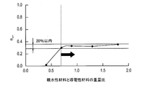
- the relationship between the electric double layer capacity and the relative humidity is such that when the change in the electric double layer capacity is constant due to the change in the relative humidity as shown by the solid line, the conductive material and the hydrophilicity having ionic conductivity. It is considered that the electric double layer capacitance is formed only from the interface with the material. Therefore, it can be considered that the transport route of water (liquid water) is continuous.
- the electric double layer capacities of 40% and 30% relative humidity are compared, and the rate of change is within 10%. It is assumed that a certain transportation route (conveying water transportation route) is formed.
- the thickness of the hydrophilic porous layer according to the present invention is not particularly limited, but the thickness of the hydrophilic porous layer according to the present invention is not particularly limited, but preferably 2 to The thickness is 40 ⁇ m, more preferably 2 to 25 ⁇ m. If the thickness of the hydrophilic porous layer is within the above range, it is preferable because both water transportability and gas diffusibility can be ensured.
- the total porosity of the hydrophilic porous layer according to the present invention is not particularly limited, but is preferably 30 to 80%, more preferably 40 to 70%. A porosity within the above range is preferable because water transportability and gas diffusibility can be ensured.
- the porosity can be obtained as a ratio to the volume of the layer by measuring the volume of pores (micropores) existing inside the layer by measuring the pore distribution by mercury porosimetry.
- the mass of the hydrophilic material in the hydrophilic porous layer according to the present invention is preferably 50 to 150 parts by mass, more preferably 70 to 130 parts by mass with respect to 100 parts by mass of the conductive material.
- the mass part of the hydrophilic material in the hydrophilic porous layer is less than 50 parts by mass with respect to 100 parts by mass of the conductive material, the ratio of the hydrophilic material to the conductive material is low, and the hydrophilic materials are mutually In some cases, it is not possible to form a continuous water (liquid water) transport route. On the other hand, when it exceeds 150 parts by mass, a water vapor transport route cannot be secured sufficiently, and the water transportability of the entire layer may be lowered.
- the hydrophilic porous layer may contain other materials in addition to the conductive material and the binder.
- the content of the conductive material and the hydrophilic material is preferably 60% by volume or more, and more preferably 80% by volume or more. More preferably, the hydrophilic porous layer is composed of a conductive material and an ion conductive material.
- the hydrophilic porous layer according to the present invention when the hydrophilic porous layer according to the present invention is applied to a membrane electrode assembly (MEA), startability under zero can be performed by high current density operation. Specifically, at the time of starting below zero, freezing can be prevented by improving water transportability, and a voltage drop due to fuel cell breakage due to freezing or a decrease in gas diffusibility can be suppressed.
- MEA membrane electrode assembly
- Examples of the conductive (carrier) material according to the present invention include artificial graphite obtained from organic compounds such as natural graphite, polyacrylonitrile, phenol resin, and furan resin, activated carbon, carbon black (oil furnace black, furnace black, channel black, kettle, etc. And carbon materials such as chain black, lamp black, thermal black, and acetylene black) and metal (Sn, Ti, etc.) oxides. Preferably, it is a carbon material.
- Vulcan (registered trademark) XC-72R Vulcan (registered trademark) P
- Black Pearls (registered trademark) 880 Black Pearls (registered trademark) 1100, Black Pearls (registered trademark) 1300, Black, manufactured by Cabot Corporation Pearls (registered trademark) 2000, Regal (registered trademark) 400, Ketjen Black International (registered trademark) EC, Ketjen Black (registered trademark) EC600JD, Mitsubishi Chemical Corporation # 3150, # 3250, etc.
- the acetylene black include Denka Black (registered trademark) manufactured by Denki Kagaku Kogyo Co., Ltd.
- the shape of the conductive material according to the present invention may be in the form of particles, granules, rods, plates, irregular particles, fibers, tubes, cones, or megaphones. Further, those obtained by post-processing these conductive materials may be used. Further, metal fine particles such as Au, Pt, Ti, Cu, Al, and stainless steel, particles of tin oxide and indium tin oxide, and electron conductive polymers such as polyaniline and fullerene can be added.
- the average particle diameter of the primary particles of the conductive material according to the present invention is preferably 60 nm or less, more preferably 5 to 50 nm, and further preferably 5 to 40 nm.
- the average particle diameter of the primary particles is 60 nm or less, a high surface area can be secured with a smaller amount of material. As a result, the thickness of the hydrophilic porous layer itself of the present invention can be reduced, and the transport resistance of the entire system can be reduced.
- primary particles are generally agglomerated of a plurality of conductive materials, for example, carbon materials such as the above-described carbon black, but the individual particles constitute aggregates. An individual particle.
- particle diameter means the maximum distance L among the distances between any two points on the contour line of the active material particles.
- the value of “average particle size” is the average value of the particle size of particles observed in several to several tens of fields using an observation means such as a scanning electron microscope (SEM) or a transmission electron microscope (TEM). The calculated value shall be adopted.
- Examples of the method for acid-treating the surface of the conductive material according to the present invention include inorganic acids such as hydrochloric acid, sulfuric acid, nitric acid, phosphoric acid, nitrous acid and phosphorous acid, organic acids such as acetic acid, formic acid and hydrofluoric acid, and these Examples thereof include a method of impregnating a known acid solution such as a mixed acid with a conductive material, a method of spraying an aqueous acid solution onto the conductive material by spraying, and the like.
- inorganic acids such as hydrochloric acid, sulfuric acid, nitric acid, phosphoric acid, nitrous acid and phosphorous acid
- organic acids such as acetic acid, formic acid and hydrofluoric acid
- the solvent used in the acid solution is mainly water, but may contain a polar organic solvent such as acetone or alcohols for the purpose of facilitating the dispersion of the conductive material.
- the concentration of the acid solution is not particularly limited as long as it is acidic.
- the impregnation time in the case of forming hydrophilic sites on the surface of the conductive material according to the present invention by the above impregnation method is not particularly limited and is appropriately selected according to the pH of the acid solution, the size of the conductive material, and the like. Is. For example, a predetermined amount of acid solution may be impregnated for about 1 to 48 hours.
- the heat treatment and firing temperature is preferably 20 to 300 ° C.
- the hydrophilic material according to the present invention is not particularly limited as long as it is a material that exhibits ionic conductivity and can bind the conductive material.
- examples thereof include polymers such as polyacrylamide, aqueous urethane resin, and silicon resin; polymer electrolytes and the like.
- a polymer electrolyte is preferred.
- the water transport property between the electrolyte membrane or the catalyst layer and the conductive material is improved, and the equilibrium can be reached in an earlier time.
- the hydrophilic material is a polymer electrolyte
- the electrolyte may be the same as or different from the polymer electrolyte used in the catalyst layer or the electrolyte membrane.
- the material can be shared, and labor saving can be achieved at the time of manufacturing.
- the hydrophilic material suitably used in the present invention is not particularly limited. Specifically, it is roughly classified into a fluorine-based electrolyte containing a fluorine atom in all or a part of the polymer skeleton and a hydrocarbon-based electrolyte not containing a fluorine atom in the polymer skeleton.
- fluorine-based electrolyte examples include perfluorocarbon sulfonic acids such as Nafion (registered trademark, manufactured by DuPont), Aciplex (registered trademark, manufactured by Asahi Kasei Co., Ltd.), and Flemion (registered trademark, manufactured by Asahi Glass Co., Ltd.).
- perfluorocarbon sulfonic acids such as Nafion (registered trademark, manufactured by DuPont), Aciplex (registered trademark, manufactured by Asahi Kasei Co., Ltd.), and Flemion (registered trademark, manufactured by Asahi Glass Co., Ltd.).
- Polymer polytrifluorostyrene sulfonic acid polymer, perfluorocarbon phosphonic acid polymer, trifluorostyrene sulfonic acid polymer, ethylene tetrafluoroethylene-g-styrene sulfonic acid polymer, ethylene-tetrafluoroethylene copolymer, poly
- a preferred example is vinylidene fluoride-perfluorocarbon sulfonic acid polymer.
- the fluorine-based electrolyte is excellent in durability and mechanical strength.
- hydrocarbon electrolyte examples include polysulfone sulfonic acid, polyaryl ether ketone sulfonic acid, polybenzimidazole alkyl sulfonic acid, polybenzimidazole alkyl phosphonic acid, polystyrene sulfonic acid, polyether ether ketone sulfonic acid, polyphenyl.
- a suitable example is sulfonic acid.
- the said hydrophilic material may be used independently and may be used together 2 or more types.
- the hydrophilic material according to the present invention covers at least a part of the conductive material, and the covering area S ion of the hydrophilic material covering at least a part of the conductive material is expressed by the following formula.
- the covering area S ion of the hydrophilic material is 200 m 2 / g or more and 1600 m 2 / g or less, drainage of liquid water can be promoted because the evaporation area is large.
- FIG. 4 is a schematic view showing a state in which the hydrophilic material 41 is coated on at least a part of the surface of the conductive material 45 according to the present invention.
- the BET nitrogen specific surface area (S BET ) 46 of the conductive material corresponds to the broken line portion. Therefore, the covering area (S ion ) 47 of the hydrophilic material, which is the portion (surface area) covered by the hydrophilic material with respect to the conductive material, overlaps with the broken line 46 and the alternate long and short dash line 48 which is the surface area inside the hydrophilic material. It corresponds to the part. That is, the hydrophilic material covering area (S ion ) 47 covered with the hydrophilic material with respect to the conductive material is an area where the conductive material 45 and the hydrophilic material 41 are in contact with each other.
- the reason for taking the ratio of 30% relative humidity and 100% relative humidity is as follows. Under a highly humidified condition, the electric double layer formed at the interface between the conductive material and water adsorbed on the surface of the conductive material or at the interface between the conductive material and the hydrophilic material is measured. On the other hand, under low humidification conditions, the electric double layer formed at the interface between the conductive material and the hydrophilic material is mainly measured.
- the electric double layer capacity according to the present invention employs a value measured by the following method.
- a membrane electrode assembly in which a hydrophilic porous layer not containing a catalyst component and a catalyst layer are arranged on different surfaces of the electrolyte membrane, respectively, is prepared, and a gas diffusion layer, a carbon separator, and a gold-plated current collector on both sides
- a cell similar to a normal fuel cell was obtained by sandwiching with a plate.
- the catalyst layer is used as a reference electrode and a counter electrode with hydrogen gas conditioned in the catalyst layer and nitrogen gas conditioned in the hydrophilic porous layer, and the potential of the hydrophilic porous layer is set to the reference electrode. Scanning was performed 5 to 10 times in the range of 0.2 to 0.6V. The scanning speed was 50 mV / s.
- FIG. 6 is a table showing the relationship between relative humidity and electric double layer capacity when various conductive materials are used, and a table showing S BET , ⁇ ion and S ion of each conductive material.
- the carbon material A is Ketjen Black EC (manufactured by Ketjen Black International Co., Ltd.)
- the carbon material B is Ketjen Black EC heat treated at 2000 to 3000 ° C. for 2 to 120 minutes. It has been applied.
- the carbon material C is acetylene black (SAB, manufactured by Denki Kagaku Kogyo)
- the carbon material D is acetylene black (OSAB, manufactured by Denki Kagaku Kogyo).
- the relationship between the mass ratio of the hydrophilic material and the conductive material and the covering ratio ⁇ ion of the hydrophilic material is based on the mass ratio between a specific hydrophilic material and the conductive material. It is confirmed that the covering ratio ⁇ ion of the hydrophilic material is constant.
- the hydrophilic material and the conductive material are in close contact with each other when the covering ratio ⁇ ion of the hydrophilic material according to the present invention is within a range of ⁇ 20% of the maximum value of the covering ratio ⁇ ion of the hydrophilic material. It is preferable that a continuous water (liquid water) transport path is formed by communicating the functional materials with each other.
- the coverage ⁇ ion of the hydrophilic material according to the present invention is preferably less than 0.7, more preferably 0.2 or more and less than 0.7, and further preferably 0.2 or more and less than 0.5.
- the covering ratio ⁇ ion of the hydrophilic material to the conductive material is 0.2 or more and less than 0.7, the water content of the hydrophilic material increases and the water diffusion coefficient in the hydrophilic material increases. As a result, since the amount of water that can be retained in the hydrophilic porous layer of the present invention increases, the water discharge performance from the catalyst layer is improved.
- the catalyst component according to the present invention is necessary when the hydrophilic porous layer according to the present invention is used as an electrode catalyst, and the cathode catalyst layer is not particularly limited as long as it has a catalytic action for oxygen reduction reaction. And known catalysts can be used in the same way.
- the anode catalyst layer is not particularly limited as long as it has a catalytic action on the hydrogen oxidation reaction in addition to a function having a catalytic action on the oxygen reduction reaction, and a known catalyst can be used in the same manner.
- the catalyst component used in the catalyst component thin film according to the present invention is preferably at least Pt or an alloy containing Pt.
- the alloy structure consists of a eutectic alloy, which is a mixture of the component elements as separate crystals, a component element completely melted into a solid solution, and a component element composed of an intermetallic compound or a compound of a metal and a nonmetal.
- a eutectic alloy which is a mixture of the component elements as separate crystals, a component element completely melted into a solid solution, and a component element composed of an intermetallic compound or a compound of a metal and a nonmetal.
- the catalyst component thin film may be formed of a plurality of layers, for example, a two-layer structure including a Pt layer and a Pt alloy layer, or a multilayer structure including other metals.
- the shape and size of the catalyst component according to the present invention are not particularly limited, and the same shape and size as known catalyst components can be used, but the catalyst component is preferably granular.
- the average particle diameter of the catalyst particles is preferably 1 to 30 nm, more preferably 1.5 to 20 nm, still more preferably 2 to 10 nm, and particularly preferably 2 to 5 nm.
- the average particle diameter of the catalyst particles is within such a range, the balance between the catalyst utilization rate related to the effective electrode area where the electrochemical reaction proceeds and the ease of loading can be appropriately controlled.
- the “average particle diameter of catalyst particles” in the present invention is the average of the crystallite diameter determined from the half-value width of the diffraction peak of the catalyst component in X-ray diffraction or the average particle diameter of the catalyst component determined from a transmission electron microscope image. It can be measured as a value.
- the hydrophilic material and the conductive material carrying the catalyst component are in close contact, and the hydrophilic material is communicated with each other to provide a continuous water (liquid water) transport route.
- a catalyst layer comprising a conductive material-hydrophilic material aggregate containing a catalyst component formed in a hydrophilic material, and the hydrophilic porous layer according to the present invention, the catalyst layer and the hydrophilic porous layer It is a gas diffusion electrode characterized by being provided in close contact with the layer.
- the catalyst layer preferably contains a catalyst component, a hydrophilic material, and a conductive material, and if necessary, an electrolyte and other additives. Further, the catalyst layer not only includes a conductive material-hydrophilic material aggregate containing a catalyst component, but also provides a water vapor transport path between the conductive material-hydrophilic material aggregate containing the catalyst component. It may be a formed layer.
- the thickness of the gas diffusion electrode may be appropriately determined in consideration of the characteristics of the obtained membrane electrode assembly, but is preferably 50 to 400 ⁇ m, more preferably 100 to 300 ⁇ m.
- a third aspect of the present invention is a membrane electrode assembly formed by sandwiching a pair of gas diffusion electrode layers according to the present invention on both sides of a polymer electrolyte membrane, or a pair of catalyst layers according to the present invention on both sides of a polymer electrolyte membrane. Is a membrane electrode assembly in which the gas diffusion layer according to the present invention is further sandwiched on the catalyst layer.
- the hydrophilic porous layer according to the present invention is preferably used for an electrode catalyst layer and / or a gas diffusion layer.
- each component of the membrane electrode assembly according to the present invention will be described.
- the polymer electrolyte used for the polymer electrolyte membrane and the polymer electrolyte used for each electrode catalyst layer may be the same or different, but the adhesion between each electrode catalyst layer and the polymer electrolyte membrane From the viewpoint of improving the properties, it is preferable to use the same one.
- the thickness of the polymer electrolyte membrane may be appropriately determined in consideration of the characteristics of the obtained membrane electrode assembly, but is preferably 1 to 50 ⁇ m, more preferably 2 to 30 ⁇ m, and particularly preferably 5 to 30 ⁇ m. . From the viewpoint of strength during film formation and durability during operation of the membrane electrode assembly, it is preferably more than 1 ⁇ m, and from the viewpoint of output characteristics during operation of the membrane electrode assembly, it is preferably less than 50 ⁇ m.
- polymer electrolyte membrane a fluorine polymer electrolyte as described above or a membrane made of a hydrocarbon resin having a sulfonic acid group can be used.
- a porous thin film formed of polytetrafluoroethylene (PTFE), polyvinylidene fluoride (PVDF) or the like may be used by impregnating an electrolyte component such as phosphoric acid or ionic liquid.
- the catalyst layer according to the present invention is a layer in which the reaction of Chemical Formula 1 actually proceeds. Specifically, the oxidation reaction of hydrogen proceeds in the anode catalyst layer, and the reduction reaction of oxygen proceeds in the cathode catalyst layer.
- the catalyst layer includes a catalyst component, a conductive carrier that supports the catalyst component, and a proton-conductive polymer electrolyte.
- the catalyst component used in the anode side catalyst layer is not particularly limited as long as it has a catalytic action in the oxidation reaction of hydrogen, and a known catalyst can be used in the same manner.
- the catalyst component used in the cathode side catalyst layer is not particularly limited as long as it has a catalytic action for the oxygen reduction reaction, and a known catalyst can be used in the same manner.
- the catalyst component in the catalyst layer is the same as that described in the above-mentioned “catalyst component” column, and is omitted here.
- the conductive carrier functions as a carrier for supporting the above-described catalyst component and an electron conduction path involved in the exchange of electrons with the catalyst component.
- the conductive carrier according to the present invention may have any specific surface area for supporting the catalyst component in a desired dispersed state and has sufficient electron conductivity, and the main component is carbon.
- a carbon-based material is preferable. Specific examples include carbon particles composed of carbon black, graphitized carbon black, activated carbon, coke, natural graphite, artificial graphite, carbon nanotube, carbon nanohorn, carbon fibril structure, and the like.
- the main component is carbon means that the main component contains carbon atoms, and is a concept that includes both carbon atoms and substantially carbon atoms. In some cases, elements other than carbon atoms may be included in order to improve the characteristics of the fuel cell. Incidentally, “substantially consisting of carbon atoms” means that contamination of about 2 to 3% by mass or less of impurities can be allowed.
- the conductive carrier according to the present invention may be the same as the conductive material.
- the BET specific surface area of the conductive carrier may be a specific surface area sufficient to carry the catalyst component in a highly dispersed state, but is preferably 20 to 1600 m 2 / g, more preferably 80 to 1200 m 2 / g.
- the specific surface area of the conductive support is in such a range, the balance between the dispersibility of the catalyst component on the conductive support and the effective utilization rate of the catalyst component can be appropriately controlled.
- the size of the conductive carrier is not particularly limited, but the average particle diameter is 5 to 200 nm, preferably from the viewpoints of easy loading, catalyst utilization, and control of the electrode catalyst layer thickness within an appropriate range.
- the thickness is preferably about 10 to 100 nm.
- the corrosion resistance of the conductive material is reduced. Since it can improve, it is preferable.
- the graphitized conductive material has a small covering area of the ion conductive material and a small evaporation area of liquid water, there is a concern about freezing below zero or flooding at room temperature.
- the present invention also provides a membrane electrode assembly for a fuel cell to which corrosion resistance of a conductive material is further provided.
- the graphitized carbon black is preferably spherical, and has an average lattice spacing d 002 of [002] plane calculated from X-ray diffraction of 0.343 to 0.358 nm and a BET specific surface area of 100 to 300 m 2 / It is preferable that it is g.
- the catalyst component can be supported on the conductive carrier by a known method.
- known methods such as impregnation method, liquid phase reduction support method, evaporation to dryness method, colloid adsorption method, spray pyrolysis method, reverse micelle (microemulsion method) can be used.
- ketjen black As the carbon carrier, ketjen black, vulcan, acetylene black, black pearl, graphitized carbon carrier (for example, graphitized ketjen black) previously heat treated at high temperature, carbon nanotube, carbon nanohorn, carbon fiber, There is mesoporous carbon.
- the catalyst layer according to the present invention includes an ion conductive polymer electrolyte in addition to the electrode catalyst.
- the polymer electrolyte is not particularly limited, and conventionally known knowledge can be referred to as appropriate.
- the ion exchange resin constituting the electrolyte membrane described above is used as the polymer electrolyte in the catalyst layer, and the conductive carrier 100 in the catalyst layer.
- the gas diffusion layer diffuses the gas (fuel gas or oxidant gas) supplied into the system through the separator channel to the catalyst layer. And a function as an electron conduction path.
- the material constituting the base material of the gas diffusion layer according to the present invention is not particularly limited, and conventionally known knowledge can be referred to as appropriate.
- a sheet-like material having conductivity and porosity such as a carbon woven fabric, a paper-like paper body, a felt, and a non-woven fabric can be used.
- the thickness of the substrate may be appropriately determined in consideration of the characteristics of the obtained gas diffusion layer, but may be about 30 to 500 ⁇ m. If the thickness of the substrate is within such a range, the balance between mechanical strength and diffusibility such as gas and water can be appropriately controlled.
- the gas diffusion layer has excellent electron conductivity, efficient transport of electrons generated by the power generation reaction is achieved, and the performance of the fuel cell is improved. Further, if the gas diffusion layer has excellent water repellency, the generated water is efficiently discharged.
- the carbon particles contained in the carbon particle layer are not particularly limited, and conventionally known materials such as carbon black, graphite, and expanded graphite can be appropriately employed. Among them, carbon black such as oil furnace black, channel black, lamp black, thermal black, acetylene black and the like can be preferably used because of excellent electron conductivity and a large specific surface area.
- the average particle diameter of the carbon particles is preferably about 10 to 100 nm. Thereby, while being able to obtain the high drainage property by capillary force, it becomes possible to improve contact property with a catalyst layer.
- Examples of the water repellent used for the carbon particle layer include the same water repellents as described above.
- fluorine-based polymer materials can be preferably used because of excellent water repellency, corrosion resistance during electrode reaction, and the like.
- the mixing ratio of the carbon particles to the water repellent in the carbon particle layer is about 90:10 to 40:60 (carbon particles: water repellent) in mass ratio in consideration of the balance between water repellency and electron conductivity. It is good to do.
- the gas diffusion layer includes a hydrophilic porous layer including the hydrophilic material (ion conductive material) and a conductive material covered with the hydrophilic material (ion conductive material), and a porous gas. And a hydrophilic treatment part in which at least a part of the hydrophilic porous layer is disposed on the gas diffusion layer base material, and at least a part of the gas diffusion layer base material is subjected to a hydrophilic treatment. It is preferable that By setting it as such a form, the surface area of the gas-liquid interface which can evaporate liquid water can further be increased, and the discharge speed of water can be improved more. Therefore, the generated water during sub-zero power generation is less likely to be accumulated in the pores, a decrease in diffusibility of the reaction gas is suppressed, and sub-zero power generation performance can be improved.
- the hydrophilic treatment part preferably includes one or more selected from the group consisting of an ion conductive material, a metal oxide, and a hydrophilic polymer.
- an ion conductive material include perfluorosulfonic acid, sulfonated polyether ether ketone, and the like.
- the metal oxide include titanium oxide and zirconium oxide.
- the hydrophilic polymer include polyacrylic acid and polyacrylamide.
- the hydrophilic porous layer may be at least partially embedded in the gas diffusion layer base material, but preferably 10 to 100% of the thickness of the hydrophilic porous layer is the gas diffusion layer. It is formed by being buried inside the substrate. When 10% or more of the portion of the hydrophilic porous layer is buried, a continuous hydrophilic network can be formed from the hydrophilic porous layer to the gas diffusion layer substrate 216. Furthermore, since the water transport distance can be shortened, the water discharge rate can be improved. In particular, it is preferable that the entire hydrophilic porous layer is buried in the gas diffusion layer base material, that is, the hydrophilic porous layer is formed inside the gas diffusion layer base material. This corresponds to a form in which 100% of the thickness of the hydrophilic porous layer is buried in the gas diffusion layer base material. If it is such a form, the above-mentioned effect can be acquired especially notably.
- binder refers to a substance having a role of adhesion.
- a fluorine-based resin having both the role of a binder and the role of water repellency is used.
- the present invention is not necessarily limited thereto, and the binder and the water-repellent material are mixed with independent substances. May be used.
- the amount of additives, alcohols (methanol, ethanol, propanol, butanol, etc.), water, water repellent, and binder used as necessary is appropriately selected according to various conditions. Is.
- Examples of the method for producing the hydrophilic porous layer according to the present invention include: 2 to 13.3% by mass of the conductive material, 1.7 to 12% by mass of the hydrophilic material, and 80 to 95% by mass of the solvent. Mix. If necessary, it is preferable to add another binder in an amount of 0 to 15% by mass with respect to the mixture to prepare a hydrophilic porous layer ink.
- the content of the catalyst component in the conductive material is preferably 10 to 80% by mass, and preferably 30 to 70% by mass. More preferred.
- the drying conditions are not particularly limited, but it is preferable to dry at 20 to 170 ° C. for about 1 to 40 minutes.
- the heat treatment step may be performed at any stage of the membrane electrode assembly preparation process, and immediately after the hydrophilic porous layer ink is applied on the substrate, the hydrophilic porous layer ink is formed. It is not limited to only.
- the atmosphere during drying is not particularly limited, but it is preferable to perform drying in an air atmosphere or an inert gas atmosphere.
- the step of drying the ink for the hydrophilic porous layer may be carried out at any stage in the process of preparing the membrane / electrode assembly. It is not restricted only to the form which dries the porous porous layer ink.
- the substrate on which the ink for the hydrophilic porous layer is applied may be appropriately selected depending on the form of the finally obtained hydrophilic porous layer, such as a catalyst layer, a gas diffusion layer, or a polytetrafluoroethylene sheet (PTFE). These polymer sheets can be used.
- the pore diameter in the hydrophilic porous layer can be made relatively large.
- the gas-phase transport resistance in the layer can be reduced.
- the pore-forming agent include organic solvents (propylene glycol, ethylene glycol) having a boiling point of 150 ° C. or higher, crystalline carbon fibers (VGCF), and the like. It is preferable to add 60% by mass.
- the pore forming agent and the solvent for preparing the ink for the hydrophilic porous layer according to the present invention may be overlapping components.
- the solvent used in the hydrophilic porous layer ink is not particularly limited, but water; methanol, ethanol, 1-propanol, 2-propanol, 1-butanol, 1-pentanol, 2-pen Examples include alcohols such as tanol and 3-pentanol; polyhydric alcohols such as ethylene glycol, propylene glycol, 1,2-butanediol, 1,3-butanediol, 1,4-butanediol, and glycerin. These may be used alone or in combination of two or more.
- the selection of the pore forming agent and the solvent is important for controlling the porosity of the hydrophilic porous layer.
- a pore-forming agent a solvent in which a high-boiling organic solvent having a boiling point exceeding 150 ° C.
- crystalline carbon fiber is used in the hydrophilic porous layer ink. Is preferably used.
- a pore-forming agent is mixed with the ink, the average pore diameter can be increased and the porosity can also be increased.
- FIG. 7 shows the difference in pore size distribution of the hydrophilic porous layer depending on the solvent type in the ink. In FIG.
- the particle diameter of the secondary particles is large, the pore diameter in the hydrophilic porous layer can be made relatively large. As a result, the gas-phase transport resistance in the layer can be reduced.
- the secondary particles in the ink composed of the conductive material, the hydrophilic material, and the solvent are secondary particles in which the conductive material according to the present invention or primary particles of the conductive material are aggregated, conductive material-hydrophilic material.
- An assembly, or a conductive material-hydrophilic material assembly precursor corresponds.
- the mode diameter and average particle diameter are calculated by a laser diffraction particle size distribution measurement method.
- the relationship between the diameter of the secondary particle of the sample A and the porosity in the Example mentioned later is shown in FIG.
- the method for preparing the ink for the hydrophilic porous layer according to the present invention is not particularly limited, and the order of mixing the hydrophilic material, the conductive material, the solvent, and, if necessary, the electrolyte and the pore former is not particularly limited.
- the solution containing the hydrophilic material according to the present invention may be adjusted by itself or a commercially available product may be used.
- the dispersion solvent of the hydrophilic material in the solution containing the hydrophilic material is not particularly limited, and examples thereof include water, methanol, ethanol, 1-propanol, and 2-propanol. In consideration of dispersibility, water, ethanol and 1-propanol are preferable. These dispersion solvents may be used alone or in combination of two or more.
- a separate mixing step may be provided in order to mix well.
- the catalyst ink is well dispersed with an ultrasonic homogenizer, or the mixed slurry is well pulverized with an apparatus such as a sand grinder, a circulating ball mill, or a circulating bead mill, and then a vacuum defoaming operation is performed.
- an apparatus such as a sand grinder, a circulating ball mill, or a circulating bead mill, and then a vacuum defoaming operation is performed.
- the addition etc. are mentioned preferably.
- the substrate coated with the ink for hydrophilic porous layer is dried.
- coating apparatuses such as a screen printer, a spray device, a bar coater, a die coater, a reverse coater, a comma coater, a gravure coater, a spray coater, and a doctor knife can be used.
- the application process may be performed once or repeated a plurality of times.
- the hydrophilic porous layer ink (1) includes, for example, a conductive material of 2.1 to 15.7% by mass and a hydrophilic material of 1.1 to 11.5% by mass. , And 80-95% by weight of solvent. If necessary, it is preferable to add another binder in an amount of 0 to 15% by mass with respect to the mixture to prepare a hydrophilic porous layer ink.
- the hydrophilic porous layer ink (2) includes 2.1 to 15.7% by mass of a conductive material carrying a catalyst component, 1.1 to 11.5% by mass of a hydrophilic material, and a solvent 80. Mix with ⁇ 95% by weight. If necessary, it is preferable to add another binder in an amount of 0 to 15% by mass with respect to the mixture to prepare a hydrophilic porous layer ink.
- Step 2 After applying the ink (1) to the substrate, it is preferable to further apply the ink (2) thereon. At this time, after the ink (1) is applied to the substrate, it may or may not be subjected to a drying step.
- Step 3 On the hydrophilic porous layer obtained from the ink (1), a hydrophilic porous layer having a conductive material carrying the catalyst component obtained from the ink (2) is laminated. A method of transferring the gas diffusion electrode to the electrolyte membrane by a predetermined method is preferable.
- the hydrophilic porous layer ink (1) comprises 2.1 to 15.7% by mass of a conductive material, 1.1 to 11.5% by mass of a hydrophilic material, and Mix with 80-95% by weight of solvent. If necessary, it is preferable to add another binder in an amount of 0 to 15% by mass with respect to the mixture to prepare a hydrophilic porous layer ink.
- the hydrophilic porous layer ink (2) includes 2.1 to 15.7% by mass of a conductive material carrying a catalyst component, 1.1 to 11.5% by mass of a hydrophilic material, and a solvent 80. Mix with ⁇ 95% by weight. If necessary, it is preferable to add another binder in an amount of 0 to 15% by mass with respect to the mixture to prepare a hydrophilic porous layer ink.
- a catalyst layer-supporting conductive carrier, a catalyst layer ink mixed with an electrolyte, and the like, and a hydrophilic porous layer ink are prepared by the above-described method.
- a hydrophilic porous layer slurry is applied on a substrate such as a PTFE sheet.
- a catalyst layer ink is applied on the hydrophilic porous layer slurry to form a catalyst layer.
- the hydrophilic porous layer-catalyst layer thus obtained is formed on the electrolyte membrane by transfer or the like.
- the gas diffusion electrode described above may be transferred onto an electrolyte membrane and bonded to the electrolyte membrane by a hot press method or the like to manufacture a membrane electrode assembly.
- the conditions for transferring by the hot press are preferably 90 to 170 ° C., 1 to 30 min, and 0.5 to 1.5 MPa.
- the step of drying the ink for hydrophilic porous layer described in the method for producing the hydrophilic porous layer may be performed at any stage in the process of preparing the membrane electrode assembly. It is not restricted to the form which dries the ink for hydrophilic porous layers immediately after apply
- the fuel cell according to the present invention preferably has a structure in which the membrane electrode assembly for a fuel cell is sandwiched between a pair of separators.
- a PEFC that is a preferred embodiment using the MEA of the present invention will be described with reference to the drawings.
- FIG. 11 is a PEFC single cell in which a fuel cell membrane electrode assembly is sandwiched between a pair of separators, and is a schematic cross-sectional view showing an example of a preferred embodiment of the present invention.
- the gasket 20 has a function of ensuring the sealability between the separator and the fuel cell membrane electrode assembly.
- the adhesive layer used as necessary preferably corresponds to the shape of the gasket and is arranged in a frame shape on the entire peripheral edge of the electrolyte membrane in consideration of securing adhesiveness.
- the gasket is disposed so as to surround the catalyst layer or the gas diffusion layer (that is, the gas diffusion electrode), and has a function of preventing leakage of supplied gas (fuel gas or oxidant gas) from the gas diffusion electrode.
- the material constituting the gasket is not particularly limited as long as it is impermeable to gases, particularly oxygen and hydrogen.
- the material constituting the gasket include rubber materials such as fluorine rubber, silicon rubber, ethylene propylene rubber (EPDM), and polyisobutylene rubber, polyethylene naphthalate (PEN), polyethylene terephthalate (PET), and polytetrafluoroethylene (PTFE).
- polymer materials such as polyvinylidene fluoride (PVdF).
- PVdF polyvinylidene fluoride
- the gasket size is not particularly limited, and may be appropriately determined in consideration of the desired gas sealability and the relationship with the size of other members.
- a membrane electrode assembly is sandwiched between separators to constitute a single cell of PEFC (solid polymer fuel cell).
- the PEFC generally has a stack structure in which a plurality of single cells are connected in series.
- the separator in addition to the function of electrically connecting each MEA in series, the separator includes a flow path and a manifold through which different fluids such as a fuel gas, an oxidant gas, and a refrigerant flow, and further maintains the mechanical strength of the stack. It also has the function.
- the material constituting the separator is not particularly limited, and conventionally known knowledge can be appropriately referred to, and examples thereof include carbon materials such as dense carbon graphite and a carbon plate, and metal materials such as stainless steel.
- the size of the separator, the shape of the flow path, and the like are not particularly limited, and may be appropriately determined in consideration of the output characteristics of the PEFC.
- the manufacturing method of PEFC is not particularly limited, and can be manufactured by appropriately referring to conventionally known knowledge in the field of fuel cells.
- the fuel cell is useful as a stationary power source in addition to a power source for a moving body such as a vehicle in which a mounting space is limited.
- a vehicle in which system start / stop and output fluctuation frequently occur more preferably It can be particularly suitably used in automobile applications.
- catalyst ink for the hydrophilic porous layer electrode catalyst powder (TEC10E50E, manufactured by Tanaka Kikinzoku Kogyo) and ionomer dispersion (Nafion (registered trademark) D2020, manufactured by DuPont) were prepared. Then, the carbon carrier and the ionomer are mixed so that the mass ratio (catalyst component-supporting conductive material / hydrophilic material) is 0.9. Further, as a solvent and a pore-forming agent, a propylene glycol solution (50%) is used as a solvent and a pore-forming agent. It was prepared by adding so that the solid content of the ink was 19%.
- the hydrophilic porous layer was applied on a polytetrafluoroethylene (PTFE) substrate by screen printing so that the amount of carbon supported was about 0.3 mg ⁇ cm ⁇ 2 . Thereafter, in order to remove organic substances, a heat treatment was performed at 130 ° C. for 30 minutes to prepare a hydrophilic porous membrane of Sample A. On this hydrophilic porous membrane, a catalyst layer was applied so that the amount of Pt supported was about 0.05 mg ⁇ cm ⁇ 2 . Thereafter, a heat treatment was again performed at 130 ° C. for 30 minutes to prepare a gas diffusion electrode layer of Sample A.
- PTFE polytetrafluoroethylene
- the gas diffusion electrode layer produced as described above was transferred to an electrolyte membrane (Nafion (registered trademark) NR211, manufactured by DuPont) to produce a membrane electrode assembly of Sample A.
- the transfer was performed under the conditions of 150 ° C., 10 min, and 0.8 Mpa.
- Sample D Acetylene black (OSAB, manufactured by Denki Kagaku Kogyo) was used in place of the carbon powder Ketjen Black EC used in the hydrophilic porous layer ink in Sample A above.
- OSAB manufactured by Denki Kagaku Kogyo
- a hydrophilic porous membrane, a gas diffusion electrode layer, and a membrane / electrode assembly of Sample D were prepared under exactly the same conditions.
- the particle size and (frequency) distribution of secondary particles of the ink for the hydrophilic porous layer were measured with a laser diffraction / scattering particle size distribution meter (Microtrac MT3000, manufactured by Nikkiso Co., Ltd.). 2-Propanol was used as a circulating solvent, and an appropriate amount of diluted catalyst ink dispersed ultrasonically was added thereto for measurement. The result is shown in FIG.
- a membrane electrode assembly in which a hydrophilic porous layer not containing a catalyst component and a catalyst layer are arranged on different surfaces of the electrolyte membrane, respectively, is prepared, and a gas diffusion layer, a carbon separator, and a gold-plated current collector on both sides
- a cell similar to a normal fuel cell was obtained by sandwiching with a plate.
- the catalyst layer is used as a reference electrode and a counter electrode with hydrogen gas conditioned in the catalyst layer and nitrogen gas conditioned in the hydrophilic porous layer, and the potential of the hydrophilic porous layer is set to the reference electrode. Scanning was performed 5 to 10 times in the range of 0.2 to 0.6V. The scanning speed was 50 mV / s.
- the relationship between the obtained current and potential showed a waveform close to a rectangle. This indicates that the oxidation and reduction reaction on the electrode has not occurred, and that charging and discharging of the electric double layer is the main factor of the current.
- the electric double layer capacity was calculated by dividing the average value of the absolute values of the oxidation current and the reduction current at a certain potential, for example, 0.3 V, by the scanning speed. This measurement was performed under various humidification conditions, and the relationship between electric double layer capacity and relative humidity was obtained.
- FIG. 6 shows the relationship between the relative humidity and the change in the electric double layer capacity
- Table 2 shows S ion , the BET nitrogen specific surface area S BET of the conductive material, and the coverage ⁇ ion of the hydrophilic material.
- Subzero power generation test Toray H-060 as a gas diffusion layer base material A gas diffusion layer provided with a hydrophilic treatment part is used for the anode (fuel electrode), and a GDL24BC made of SGL carbon is used for the cathode (air electrode).
- the body power generation area 10 cm 2
- nitrogen gas having a relative humidity of 60% was supplied to both electrodes at 50 ° C. for 3 hours for conditioning.
- dry hydrogen (1.0 NL / min) and dry air (1.0 NL / min) are applied to each electrode.
- the time from the start of power generation until the cell voltage reaches 0.2 V is 212 seconds for a battery using the gas diffusion layer without applying the hydrophilic treatment of the present invention to the anode.
- the battery of the example of the present application was 222 seconds. That is, in the battery of the present example, the power generation possible time was extended by 10 seconds or more as compared with the unimplemented battery. Therefore, according to the present invention, the generated water can be effectively discharged out of the membrane electrode assembly at the time of starting below zero, so that the voltage drop of the battery can be suppressed for a longer time.
Abstract
Description

本明細書における水の輸送抵抗Rwaterおよび水蒸気の輸送抵抗Rgasは、以下の拡散式から定義することができる。
(水蒸気の輸送抵抗 Rgas) Furthermore, since the movement from the liquid phase to the gas phase hardly occurs under the subzero condition, the movement from the liquid phase to the gas phase becomes rate-limiting. At the same time, the transport of the liquid phase (liquid water) and the transport of the gas phase (water vapor) are reversed depending on the temperature range. Therefore, at the time of starting below zero, the transportation of water (liquid water + water vapor) can be enhanced as a whole by promoting the transportation of vapor-phase water, which is particularly rate limiting, and the freezing of the produced water can be suppressed. it can.
The water transport resistance R water and the water vapor transport resistance R gas in this specification can be defined by the following diffusion equation.
(Water vapor transport resistance R gas )


気相における輸送抵抗と比較するため、活量差を駆動力として輸送される条件で算出する必要がある。例えば、Nafion(登録商標)のような材料を親水性材料として用いた場合、単位スルホン酸基量における含水量(λ)勾配を駆動力とした拡散係数が計測される。これを用いるためには、下記のような変換が必要である。 (Water transport resistance R water )
In order to compare with the transport resistance in the gas phase, it is necessary to calculate on the condition that the activity difference is transported as the driving force. For example, when a material such as Nafion (registered trademark) is used as the hydrophilic material, the diffusion coefficient with the water content (λ) gradient in the unit sulfonic acid group amount as the driving force is measured. In order to use this, the following conversion is required.


本発明に係る導電性(担体)材料としては、天然黒鉛、ポリアクリロニトリル、フェノール樹脂、フラン樹脂などの有機化合物から得られる人造黒鉛、活性炭、カーボンブラック(オイルファーネスブラック、ファーネスブラック、チャネルブラック、ケッチェンブラック、ランプブラック、サーマルブラック、アセチレンブラックなど)などの炭素材料や、金属(Sn、Tiなど)酸化物などが挙げられる。好ましくは、炭素材料である。より具体的には、キャボット社製バルカン(登録商標)XC-72R、バルカン(登録商標)P、ブラックパールズ(登録商標)880、ブラックパールズ(登録商標)1100、ブラックパールズ(登録商標)1300、ブラックパールズ(登録商標)2000、リーガル(登録商標)400、ケッチェンブラック・インターナショナル社製ケッチェンブラック(登録商標)EC、ケッチェンブラック(登録商標)EC600JD、三菱化学社製#3150、#3250などが挙げられ、アセチレンブラックとしては電気化学工業社製デンカブラック(登録商標)などが挙げられる。 (Conductive material)
Examples of the conductive (carrier) material according to the present invention include artificial graphite obtained from organic compounds such as natural graphite, polyacrylonitrile, phenol resin, and furan resin, activated carbon, carbon black (oil furnace black, furnace black, channel black, kettle, etc. And carbon materials such as chain black, lamp black, thermal black, and acetylene black) and metal (Sn, Ti, etc.) oxides. Preferably, it is a carbon material. More specifically, Vulcan (registered trademark) XC-72R, Vulcan (registered trademark) P, Black Pearls (registered trademark) 880, Black Pearls (registered trademark) 1100, Black Pearls (registered trademark) 1300, Black, manufactured by Cabot Corporation Pearls (registered trademark) 2000, Regal (registered trademark) 400, Ketjen Black International (registered trademark) EC, Ketjen Black (registered trademark) EC600JD, Mitsubishi Chemical Corporation # 3150, # 3250, etc. Examples of the acetylene black include Denka Black (registered trademark) manufactured by Denki Kagaku Kogyo Co., Ltd.
本発明に係る親水性材料は、イオン伝導性を示し、導電性材料を結着できる材料であれば、特に限定されない。例えば、ポリアクリルアミド、水性ウレタン樹脂、シリコン樹脂等の高分子;高分子電解質等が挙げられる。好適には高分子電解質である。高分子電解質を親水性材料とすることで、同じ親水性材料やイオン伝導性材料を含むMEAの構成要素(電解質膜または触媒層)と隣接して親水性多孔質層を配置する場合に安定して配置させることができ、触媒層や膜と、導電性材料との間の水輸送抵抗を低減することができる。この結果、電解質膜または触媒層と、導電性材料との間の水輸送性が向上し、より早い時間で平衡に達することができる。親水性材料が高分子電解質である場合は、当該電解質は、触媒層や電解質膜中に使用される高分子電解質と同じであってもよいし、異なってもよい。さらに、親水性多孔質層を含むMEAを作製する場合、材料を共通化することもでき、作製時の省力化が図れる。 (Hydrophilic material)
The hydrophilic material according to the present invention is not particularly limited as long as it is a material that exhibits ionic conductivity and can bind the conductive material. Examples thereof include polymers such as polyacrylamide, aqueous urethane resin, and silicon resin; polymer electrolytes and the like. A polymer electrolyte is preferred. By using a polymer electrolyte as a hydrophilic material, it is stable when a hydrophilic porous layer is placed adjacent to a MEA component (electrolyte membrane or catalyst layer) containing the same hydrophilic material or ion conductive material. The water transport resistance between the catalyst layer or membrane and the conductive material can be reduced. As a result, the water transport property between the electrolyte membrane or the catalyst layer and the conductive material is improved, and the equilibrium can be reached in an earlier time. When the hydrophilic material is a polymer electrolyte, the electrolyte may be the same as or different from the polymer electrolyte used in the catalyst layer or the electrolyte membrane. Furthermore, when manufacturing an MEA including a hydrophilic porous layer, the material can be shared, and labor saving can be achieved at the time of manufacturing.

1.サンプリング、秤量・予備乾燥
粉末は、約0.04~0.07gを精秤し、試料管に封入した。この試料管を真空乾燥器で90℃×数時間予備乾燥し、測定に供した。秤量には、島津製作所株式会社製電子天秤(AW220)を用いた。なお、塗布シートについては、これの全質量から、同面積のテフロン(基材)質量を差し引いた塗布層の正味の質量約0.03~0.04gを試料質量として用いた。 (Method for measuring nitrogen BET specific surface area)
1. Sampling, weighing and preliminary drying About 0.04 to 0.07 g of powder was precisely weighed and sealed in a sample tube. This sample tube was pre-dried at 90 ° C. for several hours in a vacuum dryer and subjected to measurement. For weighing, an electronic balance (AW220) manufactured by Shimadzu Corporation was used. For the coated sheet, the net mass of the coating layer obtained by subtracting the Teflon (base material) mass of the same area from the total mass of the coated sheet was used as the sample mass.

吸着・脱着等温線の吸着側において、相対圧(P/P0)約0.00~0.45の範囲から、BETプロットを作成することで、その傾きと切片からBET比表面積を算出する。 3. Measurement method On the adsorption side of the adsorption / desorption isotherm, create a BET plot from the relative pressure (P / P 0 ) range of approximately 0.00 to 0.45, and calculate the BET specific surface area from the slope and intercept. To do.
本発明に係る触媒成分は、本発明に係る親水性多孔質層を電極触媒として利用する場合に必要であり、カソード触媒層では、酸素の還元反応に触媒作用を有するものであれば特に制限はなく、公知の触媒が同様にして使用できる。また、アノード触媒層では、酸素の還元反応に触媒作用を有する機能以外に水素の酸化反応に触媒作用を有するものであれば特に制限はなく公知の触媒が同様にして使用できる。具体的には、白金、ルテニウム、イリジウム、ロジウム、パラジウム、オスミウム、タングステン、鉛、鉄、クロム、コバルト、ニッケル、マンガン、バナジウム、モリブデン、ガリウム、アルミニウム等の金属、及びそれらの合金等などから選択される。これらのうち、本発明に係る触媒成分薄膜に用いられる触媒成分は、少なくともPt、あるいはPtを含む合金であることが好ましい。 (Catalyst component)
The catalyst component according to the present invention is necessary when the hydrophilic porous layer according to the present invention is used as an electrode catalyst, and the cathode catalyst layer is not particularly limited as long as it has a catalytic action for oxygen reduction reaction. And known catalysts can be used in the same way. The anode catalyst layer is not particularly limited as long as it has a catalytic action on the hydrogen oxidation reaction in addition to a function having a catalytic action on the oxygen reduction reaction, and a known catalyst can be used in the same manner. Specifically, it is selected from platinum, ruthenium, iridium, rhodium, palladium, osmium, tungsten, lead, iron, chromium, cobalt, nickel, manganese, vanadium, molybdenum, gallium, aluminum and the like, and alloys thereof. Is done. Of these, the catalyst component used in the catalyst component thin film according to the present invention is preferably at least Pt or an alloy containing Pt.
本発明の第二は、前記親水性材料および触媒成分が担持された前記導電性材料が密着し、かつ前記親水性材料を相互に連通させて連続的な水(液水)の輸送経路を前記親水性材料内に形成した触媒成分を含有する導電性材料-親水性材料集合体を含む触媒層と、本発明に係る親水性多孔質層とを有し、前記触媒層と前記親水性多孔質層とが密着して設けられていることを特徴とする、ガス拡散電極である。 (Gas diffusion electrode)
In the second aspect of the present invention, the hydrophilic material and the conductive material carrying the catalyst component are in close contact, and the hydrophilic material is communicated with each other to provide a continuous water (liquid water) transport route. A catalyst layer comprising a conductive material-hydrophilic material aggregate containing a catalyst component formed in a hydrophilic material, and the hydrophilic porous layer according to the present invention, the catalyst layer and the hydrophilic porous layer It is a gas diffusion electrode characterized by being provided in close contact with the layer.
本発明の第三は、高分子電解質膜の両側に一対の本発明に係るガス拡散電極層を挟持してなる膜電極接合体、または高分子電解質膜の両側に一対の本発明に係る触媒層を挟持し、さらに当該触媒層上に本発明に係るガス拡散層を挟持してなる膜電極接合体である。 (Membrane electrode assembly)
A third aspect of the present invention is a membrane electrode assembly formed by sandwiching a pair of gas diffusion electrode layers according to the present invention on both sides of a polymer electrolyte membrane, or a pair of catalyst layers according to the present invention on both sides of a polymer electrolyte membrane. Is a membrane electrode assembly in which the gas diffusion layer according to the present invention is further sandwiched on the catalyst layer.
本発明の膜電極接合体に用いられる高分子電解質膜としては、特に限定されず、電極触媒層に用いた親水性材料と同様の高分子電解質からなる膜が挙げられる。また、デュポン社製の各種のNafion(登録商標)やフレミオン(登録商標)に代表されるパーフルオロスルホン酸膜、ダウケミカル社製のイオン交換樹脂、エチレン-四フッ化エチレン共重合体樹脂膜、トリフルオロスチレンをベース高分子とする樹脂膜などのフッ素系高分子電解質や、スルホン酸基を有する炭化水素系樹脂系膜など、一般的に市販されている高分子型電解質膜、高分子微多孔膜に液体電解質を含浸させた膜、多孔質体に高分子電解質を充填させた膜などを用いてもよい。前記高分子電解質膜に用いられる高分子電解質と、各電極触媒層に用いられる高分子電解質とは、同じであっても異なっていてもよいが、各電極触媒層と高分子電解質膜との密着性を向上させる観点から、同じものを用いるのが好ましい。 (Electrolyte membrane)
The polymer electrolyte membrane used in the membrane / electrode assembly of the present invention is not particularly limited, and examples thereof include a membrane made of the same polymer electrolyte as the hydrophilic material used in the electrode catalyst layer. Also, perfluorosulfonic acid membranes represented by various Nafion (registered trademark) and Flemion (registered trademark) manufactured by DuPont, ion exchange resins, ethylene-tetrafluoroethylene copolymer resin membranes manufactured by Dow Chemical Company, Fluoropolymer electrolytes such as resin membranes based on trifluorostyrene, hydrocarbon resin membranes with sulfonic acid groups, and other polymer electrolyte membranes that are generally commercially available, polymer microporous A membrane in which a membrane is impregnated with a liquid electrolyte, a membrane in which a porous body is filled with a polymer electrolyte, or the like may be used. The polymer electrolyte used for the polymer electrolyte membrane and the polymer electrolyte used for each electrode catalyst layer may be the same or different, but the adhesion between each electrode catalyst layer and the polymer electrolyte membrane From the viewpoint of improving the properties, it is preferable to use the same one.
本発明に係る親水性多孔質層をガス拡散層にだけ使用する場合、本発明に係る触媒層は、実際に上記化学式1の反応が進行する層である。具体的には、アノード触媒層では水素の酸化反応が進行し、カソード触媒層では酸素の還元反応が進行する。当該触媒層は、触媒成分、触媒成分を担持する導電性担体、およびプロトン伝導性の高分子電解質を含む。上記アノード側触媒層に用いられる触媒成分は、水素の酸化反応に触媒作用を有するものであれば特に制限はなく公知の触媒が同様にして使用できる。また、カソード側触媒層に用いられる触媒成分もまた、酸素の還元反応に触媒作用を有するものであれば特に制限はなく公知の触媒が同様にして使用できる。触媒層における触媒成分は、上記「触媒成分」の欄で説明したものと同様であるためここでは省略する。 (Catalyst layer)
When the hydrophilic porous layer according to the present invention is used only for the gas diffusion layer, the catalyst layer according to the present invention is a layer in which the reaction of
本発明に係る親水性多孔質層を触媒層にだけ使用する場合において、ガス拡散層はセパレータ流路を介して系内に供給されたガス(燃料ガスまたは酸化剤ガス)の触媒層への拡散を促進する機能、および電子伝導パスとしての機能を有する。 (Gas diffusion layer)
In the case where the hydrophilic porous layer according to the present invention is used only for the catalyst layer, the gas diffusion layer diffuses the gas (fuel gas or oxidant gas) supplied into the system through the separator channel to the catalyst layer. And a function as an electron conduction path.
本発明に係る親水性多孔質層およびガス拡散電極の好適な製造法の一例を以下説明する。 (Method for producing hydrophilic porous layer and gas diffusion electrode)
An example of a preferred method for producing the hydrophilic porous layer and the gas diffusion electrode according to the present invention will be described below.
本発明に係る親水性多孔質層の作製方法としては、例えば、導電性材料2~13.3質量%と、親水性材料1.7~12質量%と、および溶媒80~95質量%とを混合する。そして、必要によりその他バインダーを前記の混合物に対して0~15質量%添加して親水性多孔質層用インクを調製することが好ましい。 (Method for producing hydrophilic porous layer)
Examples of the method for producing the hydrophilic porous layer according to the present invention include: 2 to 13.3% by mass of the conductive material, 1.7 to 12% by mass of the hydrophilic material, and 80 to 95% by mass of the solvent. Mix. If necessary, it is preferable to add another binder in an amount of 0 to 15% by mass with respect to the mixture to prepare a hydrophilic porous layer ink.
本発明に係るガス拡散電極の作製方法は、導電性材料、親水性材料、および溶媒を含む親水性多孔質層用インク(1)と、触媒成分を担持した導電性材料、親水性材料、および溶媒からなる親水性多孔質層用インク(2)と、を順次塗布して作製することが好ましい。 (Manufacturing method of gas diffusion electrode)
A method for producing a gas diffusion electrode according to the present invention includes a hydrophilic porous layer ink (1) containing a conductive material, a hydrophilic material, and a solvent, a conductive material carrying a catalyst component, a hydrophilic material, and It is preferable that the hydrophilic porous layer ink (2) made of a solvent is sequentially applied and produced.
「膜電極接合体の製造方法」 (Step 3) The order of the electrolyte membrane, the hydrophilic porous layer having a conductive material carrying the catalyst component obtained from the ink (2), and the hydrophilic porous layer obtained from the ink (1) A membrane / electrode assembly having a gas diffusion electrode laminated in the above is obtained.
"Production method of membrane electrode assembly"
本発明に係る燃料電池は、上記燃料電池用膜電極接合体が一対のセパレータにより挟持されてなる構造であることが好ましい。
次に、図面を参照しながら本発明のMEAを用いる好適な実施形態であるPEFCについて説明する。 (Fuel cell)
The fuel cell according to the present invention preferably has a structure in which the membrane electrode assembly for a fuel cell is sandwiched between a pair of separators.
Next, a PEFC that is a preferred embodiment using the MEA of the present invention will be described with reference to the drawings.
ガスケットは、触媒層またはガス拡散層(すなわち、ガス拡散電極)を包囲するように配置され、供給されたガス(燃料ガスまたは酸化剤ガス)のガス拡散電極からの漏出を防止する機能を有する。 (gasket)
The gasket is disposed so as to surround the catalyst layer or the gas diffusion layer (that is, the gas diffusion electrode), and has a function of preventing leakage of supplied gas (fuel gas or oxidant gas) from the gas diffusion electrode.
膜電極接合体をセパレータで挟持してPEFC(固体高分子型燃料電池)の単セルを構成する。PEFCは、単セルが複数個直列に接続されてなるスタック構造を有するのが一般的である。この際、セパレータは、各MEAを直列に電気的に接続する機能に加えて、燃料ガスおよび酸化剤ガス並びに冷媒といった異なる流体を流す流路やマニホールドを備え、さらにはスタックの機械的強度を保つといった機能をも有する。 (Separator)
A membrane electrode assembly is sandwiched between separators to constitute a single cell of PEFC (solid polymer fuel cell). The PEFC generally has a stack structure in which a plurality of single cells are connected in series. At this time, in addition to the function of electrically connecting each MEA in series, the separator includes a flow path and a manifold through which different fluids such as a fuel gas, an oxidant gas, and a refrigerant flow, and further maintains the mechanical strength of the stack. It also has the function.
1.サンプルAの作製
親水性多孔質層用インクは、導電性材料として、カーボン粉末(ケッチェンブラックEC, ケッチェン・ブラック・インターナショナル(株))を用意した。親水性材料として、アイオノマー分散液(Nafion(登録商標) D2020, DuPont社製)とを用意した。そして、カーボン粉末とアイオノマーとの質量比(導電性材料/親水性材料)が0.7となるよう混合し、さらに、溶媒および造孔剤として、プロピレングリコール溶液(50%)を、インクの固形分率が12%となるよう添加して調製した。 (1) Manufacturing method of hydrophilic porous membrane, gas diffusion electrode layer and membrane electrode assembly Preparation of Sample A For the hydrophilic porous layer ink, carbon powder (Ketjen Black EC, Ketjen Black International Co., Ltd.) was prepared as a conductive material. As a hydrophilic material, an ionomer dispersion (Nafion (registered trademark) D2020, manufactured by DuPont) was prepared. Then, the carbon powder and the ionomer are mixed so that the mass ratio (conductive material / hydrophilic material) is 0.7, and further, a propylene glycol solution (50%) is used as a solvent and a pore-forming agent as a solid ink. It was prepared by adding a fraction of 12%.
上記サンプルAにおける親水性多孔質層用インクで使用したカーボン粉末のケッチェンブラックECの代わりに、ケッチェンブラックECに熱処理(3000℃で2時間)を施したものを使用した。これ以外全く同一条件でサンプルBの親水性多孔質膜、ガス拡散電極層および膜電極接合体を作製した。 2. Preparation of Sample B Instead of the carbon powder Ketjen Black EC used in the hydrophilic porous layer ink in Sample A above, Ketjen Black EC subjected to heat treatment (at 3000 ° C. for 2 hours) was used. A hydrophilic porous membrane, a gas diffusion electrode layer, and a membrane electrode assembly of Sample B were produced under exactly the same conditions.
上記サンプルAにおける親水性多孔質層用インクで使用したカーボン粉末のケッチェンブラックECの代わりに、アセチレンブラック(SAB、電気化学工業製)を使用した。これ以外全く同一条件でサンプルCの親水性多孔質膜、ガス拡散電極層および膜電極接合体を作製した。 3. Preparation of Sample C Acetylene black (SAB, manufactured by Denki Kagaku Kogyo) was used in place of the carbon powder Ketjen Black EC used in the hydrophilic porous layer ink in Sample A above. A hydrophilic porous membrane, a gas diffusion electrode layer, and a membrane electrode assembly of Sample C were produced under exactly the same conditions.
上記サンプルAにおける親水性多孔質層用インクで使用したカーボン粉末のケッチェンブラックECの代わりに、アセチレンブラック(OSAB、電気化学工業製)を使用した。これ以外全く同一条件でサンプルDの親水性多孔質膜、ガス拡散電極層および膜電極接合体を作製した。 4). Preparation of Sample D Acetylene black (OSAB, manufactured by Denki Kagaku Kogyo) was used in place of the carbon powder Ketjen Black EC used in the hydrophilic porous layer ink in Sample A above. A hydrophilic porous membrane, a gas diffusion electrode layer, and a membrane / electrode assembly of Sample D were prepared under exactly the same conditions.
1.空孔分布の測定
上記の方法により得られたサンプルAの親水性多孔質層を水銀圧入法により、空孔分布を測定した。その結果を、図8に示す。親水性多孔質層の空孔分布は、自動ポロシメーター(オートポアIV 9510型、マイクロメリティクス社製)を用いて、3nm~400nmの空孔径範囲で測定した。 (2) Evaluation Measurement of pore distribution The pore distribution of the hydrophilic porous layer of sample A obtained by the above method was measured by mercury porosimetry. The result is shown in FIG. The pore distribution of the hydrophilic porous layer was measured in a pore diameter range of 3 nm to 400 nm using an automatic porosimeter (Autopore IV 9510 type, manufactured by Micromeritics).
上記の方法により得られたサンプルA~Dの親水性多孔質層について、相対湿度と電気二重層容量の変化との関係、Sion、導電性材料のBET窒素比表面積SBET、および親水性材料の被覆率θionを求めた。 2. Relationship between relative humidity and change in electric double layer capacity Regarding the hydrophilic porous layer of samples A to D obtained by the above method, relation between relative humidity and change in electric double layer capacity, S ion , conductive material The BET nitrogen specific surface area S BET and the covering ratio θ ion of the hydrophilic material were determined.

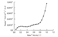
まず、水の活量と含水量との関係をBELSORP18 PLUS-HT(日本ベル製)を用いて測定した。これと、含水量と水の拡散係数の関係(Journal of The Electrochemical Society,147 (9) 3171-3177(2000))から、水の活量と輸送抵抗との関係を得た。 3. Electrolyte water transportability (reciprocal of transport resistance)
First, the relationship between the water activity and the water content was measured using BELSORP18 PLUS-HT (manufactured by Nippon Bell). From this, and the relationship between the water content and the diffusion coefficient of water (Journal of The Electrochemical Society, 147 (9) 3171-3177 (2000)), the relationship between the water activity and the transport resistance was obtained.
1次粒径を確認するために、カーボン(KB)粉末を、HD-2000(走査型電子顕微鏡、日立製作所製)を用いて観察した。その結果を図10に示す。 4). Observation of Carbon (KB) Powder In order to confirm the primary particle size, the carbon (KB) powder was observed using HD-2000 (scanning electron microscope, manufactured by Hitachi, Ltd.). The result is shown in FIG.
親水性を示す箇所を確認し、アイオノマーのフッ素原子を確認するために、実施例のガス拡散層を、SEM(走査型電子顕微鏡、日本電子社製、JSM-6380LA)を用いて観察し、EPMA(電子線マイクロアナラザ)を用いて解析した。その結果を図12に示す。(A)がSEMの観察結果であり、(B)がEPMAの観察結果である。EPMAにて、写真上部の散在している白部分が親水処理部であり、フッ素原子が分散している部分である。 5). Observation of Gas Diffusion Layer In order to confirm the location showing hydrophilicity and to confirm the fluorine atom of the ionomer, the gas diffusion layer of the examples was subjected to SEM (scanning electron microscope, manufactured by JEOL Ltd., JSM-6380LA). And analyzed using EPMA (electron beam microanalyzer). The result is shown in FIG. (A) is an observation result of SEM, and (B) is an observation result of EPMA. In EPMA, the scattered white portion at the top of the photograph is a hydrophilic processing portion, and is a portion where fluorine atoms are dispersed.
ガス拡散層基材として東レ製 H-060に親水処理部を設けたガス拡散層をアノード(燃料極)に使用し、カソード(空気極)にSGLカーボン製GDL24BCを使用した膜電極接合体(発電面積10cm2)を小型単セルに組み込み、零下発電性能を確認した。具体的には、はじめに、コンディショニングのために50℃において両極に相対湿度60%の窒素ガスを3時間供給した。次に、小型単セルの温度を-20℃まで約1時間で冷却し、十分温度が安定した後、各極にそれぞれ乾燥水素(1.0NL/min)と乾燥空気(1.0NL/min)の供給を開始し、90秒経過した後、負荷(電流密度:40mA/cm2)を瞬時に取り出した。零下環境であるため生成水が凍結しセル電圧が低下するが、それまでの時間が長いものほど生成水の気相排出性が高いと考えた。そこで、発電開始からセル電圧が0.2Vとなるまでの時間を比較した。その結果を表3に示す。 6). Subzero power generation test Toray H-060 as a gas diffusion layer base material A gas diffusion layer provided with a hydrophilic treatment part is used for the anode (fuel electrode), and a GDL24BC made of SGL carbon is used for the cathode (air electrode). The body (

2 カソード側セパレータ、
3、4 ガス供給溝、
5 カソード側電極触媒層、
6 カソード側ガス拡散層、
7 アノード側セパレータ、
8 固体高分子電解質膜、
9 アノード側ガス拡散層、
10 親水性多孔質層、
11 高分子電解質膜、
12a アノード触媒層、
12c カソード触媒層、
13a アノードガス拡散層、
13c カソードガス拡散層、
14a アノードミクロポア層、
14c カソードミクロポア層、
15a アノードマクロポア層、
15c カソードマクロポア層、
16a アノードガス拡散電極、
16c カソードガス拡散電極、
17 カソードガス流路、
18 アノードガス流路、
19 アノード側電極触媒層、
20 親水性材料-導電性材料集合体、
21、41 親水性材料、
22 連続的な水の通り道である輸送経路(連通した水の輸送経路)、
23 水蒸気の輸送経路、
24 液水から水蒸気のルート、
25、45 導電性材料、
46 導電性材料のBET窒素比表面積(SBET)、
47 親水性材料の被覆面積(Sion)、
48 親水性材料の内側の表面、
49 微細な空孔、
100 固体高分子電解質型燃料電池、
100’ 膜電極接合体、
101 アノード(電極)触媒層、
102 カソード(電極)触媒層。 1 membrane electrode assembly,
2 cathode separator,
3, 4 Gas supply groove,
5 Cathode side electrocatalyst layer,
6 Cathode side gas diffusion layer,
7 Anode separator,
8 solid polymer electrolyte membrane,
9 Anode-side gas diffusion layer,
10 hydrophilic porous layer,
11 Polymer electrolyte membrane,
12a anode catalyst layer,
12c cathode catalyst layer,
13a Anode gas diffusion layer,
13c cathode gas diffusion layer,
14a Anode micropore layer,
14c cathode micropore layer,
15a anode macropore layer,
15c cathode macropore layer,
16a Anode gas diffusion electrode,
16c cathode gas diffusion electrode,
17 Cathode gas flow path,
18 anode gas flow path,
19 Anode side electrocatalyst layer,
20 hydrophilic material-conductive material aggregate,
21, 41 hydrophilic material,
22 Transport route (continuous water transport route), which is a continuous water path
23 Water vapor transport route,
24 Liquid water to water vapor route,
25, 45 conductive material,
46 BET nitrogen specific surface area (S BET ) of conductive material,
47 Covering area of hydrophilic material (S ion ),
48 inner surface of hydrophilic material,
49 fine pores,
100 solid polymer electrolyte fuel cell,
100 'membrane electrode assembly,
101 Anode (electrode) catalyst layer,
102 Cathode (electrode) catalyst layer.
Claims (22)
- 親水性材料および導電性材料が密着し、かつ前記親水性材料を相互に連通させて連続的な水の輸送経路を前記親水性材料内に形成した導電性材料-親水性材料集合体を有し、前記導電性材料-親水性材料集合体相互間に水蒸気の輸送経路を形成した層であって、
前記水の輸送経路における水の輸送抵抗Rwaterが、前記水蒸気の輸送経路における水蒸気の輸送抵抗Rgasより大きいことを特徴とする、親水性多孔質層。 A conductive material-hydrophilic material assembly in which the hydrophilic material and the conductive material are in close contact with each other and the hydrophilic material is in communication with each other to form a continuous water transport path in the hydrophilic material; A layer in which a water vapor transport path is formed between the conductive material and the hydrophilic material aggregate,
The hydrophilic porous layer, wherein a water transport resistance R water in the water transport path is greater than a water vapor transport resistance R gas in the water vapor transport path. - 前記親水性材料は前記導電性材料の表面の少なくとも一部を被覆しており、前記導電性材料の表面の少なくとも一部を被覆した親水性材料の被覆面積Sionが、以下の式

- 前記親水性材料の被覆率θionは、0.7未満であることを特徴とする、請求項2に記載の親水性多孔質層。 The hydrophilic porous layer according to claim 2, wherein a coverage θ ion of the hydrophilic material is less than 0.7.
- 前記導電性材料は、予め表面を酸処理していることを特徴とする、請求項1~3のいずれか1項に記載の親水性多孔質層。 The hydrophilic porous layer according to any one of claims 1 to 3, wherein the surface of the conductive material is previously acid-treated.
- 前記導電性材料の1次粒子の平均粒子径は、60nm以下であることを特徴とする、請求項1~4のいずれか1項に記載の親水性多孔質層。 The hydrophilic porous layer according to any one of claims 1 to 4, wherein an average particle diameter of primary particles of the conductive material is 60 nm or less.
- 親水性材料の被覆率θionは、親水性材料の被覆率θionの最大値の±20%領域であることを特徴とする、請求項1~5のいずれか1項に記載の親水性多孔質層。 The hydrophilic porous material according to any one of claims 1 to 5, wherein the covering ratio θ ion of the hydrophilic material is in a range of ± 20% of the maximum value of the covering ratio θ ion of the hydrophilic material. Quality layer.
- 前記親水性材料および触媒成分が担持された前記導電性材料が密着し、かつ前記親水性材料を相互に連通させて連続的な水の輸送経路を前記親水性材料内に形成した触媒成分を含有する導電性材料-親水性材料集合体を有する触媒層と、
請求項1~6のいずれか1項に記載の親水性多孔質層と、
を有し、前記触媒層と前記親水性多孔質層とが密着して設けられていることを特徴とする、ガス拡散電極。 The conductive material carrying the hydrophilic material and the catalyst component is in close contact with each other, and includes a catalyst component in which the hydrophilic material is communicated with each other to form a continuous water transport path in the hydrophilic material. A catalyst layer having a conductive material-hydrophilic material aggregate to be
The hydrophilic porous layer according to any one of claims 1 to 6,
A gas diffusion electrode, wherein the catalyst layer and the hydrophilic porous layer are provided in close contact with each other. - 導電性材料、親水性材料、および溶媒を含み、かつインク中における二次粒子の平均粒子径が、0.5μm以上であり、モード径が0.35μm以上であるインクを用いて作製したことを特徴とする、請求項1~6のいずれか1項に記載の親水性多孔質層。 It was produced using an ink containing a conductive material, a hydrophilic material, and a solvent, and having an average particle diameter of secondary particles in the ink of 0.5 μm or more and a mode diameter of 0.35 μm or more. The hydrophilic porous layer according to any one of claims 1 to 6, characterized in that it is characterized in that
- 造孔剤を含む、インクを用いて作製したことを特徴とする、請求項1~6および8のいずれか1項に記載の親水性多孔質層。 The hydrophilic porous layer according to any one of claims 1 to 6 and 8, wherein the hydrophilic porous layer is produced using an ink containing a pore forming agent.
- 前記親水性材料および前記親水性材料に被覆される導電性材料を含む親水性多孔質層と、多孔質性のガス拡散層基材と、を含むガス拡散層が形成され、
前記親水性多孔質層の少なくとも一部が、前記ガス拡散層基材に設置され、
前記ガス拡散層基材の少なくとも一部が、親水処理された親水処理部である、請求項7に記載のガス拡散電極。 A gas diffusion layer comprising the hydrophilic material and a hydrophilic porous layer containing a conductive material coated with the hydrophilic material, and a porous gas diffusion layer base material is formed;
At least a portion of the hydrophilic porous layer is disposed on the gas diffusion layer substrate;
The gas diffusion electrode according to claim 7, wherein at least a part of the gas diffusion layer base material is a hydrophilic treatment portion subjected to a hydrophilic treatment. - 前記親水性多孔質層の少なくとも一部が、前記ガス拡散層の内部に形成される、請求項10に記載のガス拡散電極。 The gas diffusion electrode according to claim 10, wherein at least a part of the hydrophilic porous layer is formed inside the gas diffusion layer.
- 前記ガス拡散層基材における水蒸気の有効拡散係数D(m2/s)は、1気圧、-20℃で、下記式を満たす、請求項10または11に記載のガス拡散電極:

- 前記ガス拡散層基材中の空孔の最小空孔径が1μm以上である、請求項10~12のいずれか1項に記載のガス拡散電極。 The gas diffusion electrode according to any one of claims 10 to 12, wherein the minimum pore diameter of the pores in the gas diffusion layer base material is 1 µm or more.
- 前記親水処理部は、イオン伝導性材料、金属酸化物、および親水性ポリマーからなる群より選択される1以上を含む、請求項10~13のいずれか1項に記載のガス拡散電極。 The gas diffusion electrode according to any one of claims 10 to 13, wherein the hydrophilic treatment portion includes one or more selected from the group consisting of an ion conductive material, a metal oxide, and a hydrophilic polymer.
- ガス拡散層と、親水性材料および触媒成分を担持した導電性担体を含む触媒層とを有し、前記触媒層は、前記親水性材料相互が密着することにより連続的な液水の輸送経路を形成する構造を有する、請求項10~14のいずれか1項に記載のガス拡散電極。 A gas diffusion layer, and a catalyst layer including a conductive support carrying a hydrophilic material and a catalyst component, and the catalyst layer provides a continuous liquid water transport path by bringing the hydrophilic materials into close contact with each other. The gas diffusion electrode according to any one of claims 10 to 14, which has a structure to be formed.
- 前記親水性材料のEWが1000g/eq.以下である、請求項15に記載のガス拡散電極。 EW of the hydrophilic material is 1000 g / eq. The gas diffusion electrode according to claim 15, which is the following.
- 導電性材料、親水性材料、および溶媒を含む親水性多孔質層用インク(1)と、触媒成分を担持した導電性材料、親水性材料、および溶媒からなる親水性多孔質層用インク(2)とを順次塗布して作製することを特徴とする、請求項7および10~16のいずれか1項に記載のガス拡散電極の製造方法。 Hydrophilic porous layer ink (1) containing a conductive material, a hydrophilic material, and a solvent, and a hydrophilic porous layer ink (2) comprising a conductive material carrying a catalyst component, a hydrophilic material, and a solvent The method for producing a gas diffusion electrode according to any one of claims 7 and 10 to 16, wherein the gas diffusion electrode is produced by sequentially applying the following.
- ガス拡散層基材の表面に親水剤を含む溶液を塗布する段階と、
前記溶液が乾燥する前に、導電性材料、親水性材料、および溶媒を含む親水性多孔質層用インクをさらに塗布し、乾燥させる段階と、
を含む、請求項7および10~16のいずれか1項に記載のガス拡散電極の製造方法。 Applying a solution containing a hydrophilic agent to the surface of the gas diffusion layer substrate;
Before the solution dries, further applying and drying a hydrophilic porous layer ink containing a conductive material, a hydrophilic material, and a solvent; and
The method for producing a gas diffusion electrode according to any one of claims 7 and 10 to 16, comprising: - 請求項1~6および8~9のいずれか1項に記載の親水性多孔質層を有する、膜電極接合体。 A membrane / electrode assembly having the hydrophilic porous layer according to any one of claims 1 to 6 and 8 to 9.
- 請求項7および10~16のいずれか1項に記載のガス拡散電極を有する、膜電極接合体。 A membrane electrode assembly having the gas diffusion electrode according to any one of claims 7 and 10 to 16.
- 請求項19または20に記載の膜電極接合体を有する燃料電池。 A fuel cell comprising the membrane electrode assembly according to claim 19 or 20.
- 請求項21に記載の燃料電池を搭載した車両。 A vehicle equipped with the fuel cell according to claim 21.
Priority Applications (4)
| Application Number | Priority Date | Filing Date | Title |
|---|---|---|---|
| EP10792188A EP2448047A1 (en) | 2009-06-26 | 2010-06-25 | Hydrophilic porous layer for fuel cells, gas diffusion electrode and manufacturing method thereof, and membrane electrode assembly |
| CN201080028661.5A CN102804466B (en) | 2009-06-26 | 2010-06-25 | The hydrophilic porous layer of fuel cell, gas-diffusion electrode and manufacture method thereof and membrane electrode assembly |
| US13/380,709 US20120100461A1 (en) | 2009-06-26 | 2010-06-25 | Hydrophilic porous layer for fuel cells, gas diffusion electrode and manufacturing method thereof, and membrane electrode assembly |
| CA2766279A CA2766279A1 (en) | 2009-06-26 | 2010-06-25 | Hydrophilic porous layer for fuel cells, gas diffusion electrode and manufacturing method thereof, and membrane electrode assembly |
Applications Claiming Priority (2)
| Application Number | Priority Date | Filing Date | Title |
|---|---|---|---|
| JP2009-153012 | 2009-06-26 | ||
| JP2009153012 | 2009-06-26 |
Publications (1)
| Publication Number | Publication Date |
|---|---|
| WO2010150870A1 true WO2010150870A1 (en) | 2010-12-29 |
Family
ID=43386639
Family Applications (1)
| Application Number | Title | Priority Date | Filing Date |
|---|---|---|---|
| PCT/JP2010/060825 WO2010150870A1 (en) | 2009-06-26 | 2010-06-25 | Hydrophilic porous layer for fuel cells, gas diffusion electrode and manufacturing method thereof, and membrane electrode assembly |
Country Status (6)
| Country | Link |
|---|---|
| US (1) | US20120100461A1 (en) |
| EP (1) | EP2448047A1 (en) |
| JP (1) | JP5488254B2 (en) |
| CN (1) | CN102804466B (en) |
| CA (1) | CA2766279A1 (en) |
| WO (1) | WO2010150870A1 (en) |
Families Citing this family (16)
| Publication number | Priority date | Publication date | Assignee | Title |
|---|---|---|---|---|
| WO2012053303A1 (en) * | 2010-10-22 | 2012-04-26 | 日産自動車株式会社 | Electrocatalyst for solid polymer fuel cell |
| US9044566B2 (en) * | 2013-03-01 | 2015-06-02 | Reaction Systems, Llc | Advanced supported liquid membranes for carbon dioxide control in extravehicular activity applications |
| WO2014175098A1 (en) | 2013-04-25 | 2014-10-30 | 日産自動車株式会社 | Catalyst, electrode catalyst layer using said catalyst, membrane electrode assembly, and fuel cell |
| WO2014175097A1 (en) * | 2013-04-25 | 2014-10-30 | 日産自動車株式会社 | Catalyst, method for producing same, and electrode catalyst layer using said catalyst |
| WO2014185909A1 (en) * | 2013-05-16 | 2014-11-20 | United Technologies Corporation | Flow battery with hydrated ion-exchange membrane having maximum water domain cluster sizes |
| JP2015032415A (en) * | 2013-08-01 | 2015-02-16 | 本田技研工業株式会社 | Electrolyte membrane-electrode structure |
| DK2869382T3 (en) * | 2013-10-30 | 2019-04-01 | Basf Se | Improved diaphragm electrode devices |
| US10367218B2 (en) | 2014-10-29 | 2019-07-30 | Nissan Motor Co., Ltd. | Electrode catalyst layer for fuel cell, method for producing the same, and membrane electrode assembly and fuel cell using the catalyst layer |
| JP6571961B2 (en) * | 2015-03-25 | 2019-09-04 | 株式会社東芝 | ELECTRODE FOR FUEL CELL, MEMBRANE ELECTRODE COMPLEX FOR FUEL CELL, AND FUEL CELL |
| JP6575602B2 (en) * | 2015-09-09 | 2019-09-25 | 日産自動車株式会社 | ELECTRODE CATALYST LAYER FOR FUEL CELL AND METHOD FOR PRODUCING THE SAME, AND MEMBRANE ELECTRODE ASSEMBLY, FUEL CELL, AND VEHICLE USING THE CATALYST |
| GB2556836B (en) * | 2015-09-17 | 2021-09-22 | Figaro Eng | Electrochemical gas sensor |
| DE102017204096A1 (en) * | 2017-03-13 | 2018-09-13 | Siemens Aktiengesellschaft | Production of gas diffusion electrodes with ion transport resins for the electrochemical reduction of CO2 to chemical recyclables |
| US11056698B2 (en) | 2018-08-02 | 2021-07-06 | Raytheon Technologies Corporation | Redox flow battery with electrolyte balancing and compatibility enabling features |
| EP3836266A4 (en) * | 2018-08-09 | 2021-09-08 | Mitsui Mining & Smelting Co., Ltd. | Electrode catalyst layer for fuel cells and solid polymer fuel cell using same |
| CN111240376B (en) * | 2018-11-29 | 2021-06-01 | 中国科学院大连化学物理研究所 | Passive air pressure adjusting device |
| US11271226B1 (en) | 2020-12-11 | 2022-03-08 | Raytheon Technologies Corporation | Redox flow battery with improved efficiency |
Citations (8)
| Publication number | Priority date | Publication date | Assignee | Title |
|---|---|---|---|---|
| JPH06203852A (en) * | 1993-01-05 | 1994-07-22 | Sanyo Electric Co Ltd | Manufacture of bonded body of electrode-polyelectrolyte film |
| JPH07176310A (en) * | 1993-12-20 | 1995-07-14 | Sanyo Electric Co Ltd | Electrode and junction body between electrode and ion exchange membrane |
| JPH08180879A (en) * | 1994-12-21 | 1996-07-12 | Toyota Motor Corp | Electrode for fuel cell, its manufacture and manufacture of generating layer |
| JPH10241701A (en) * | 1996-12-27 | 1998-09-11 | Japan Storage Battery Co Ltd | Gas diffusion electrode and solid polymer electrolyte film, manufacture thereof, and solid polymer electrolyte type fuel cell |
| JP2004296435A (en) * | 2003-03-13 | 2004-10-21 | Toray Ind Inc | Electrode catalyst layer, its manufacturing method, and solid polymer type fuel cell using the same |
| JP3778506B2 (en) | 2002-11-08 | 2006-05-24 | 本田技研工業株式会社 | Electrode for polymer electrolyte fuel cell |
| JP2006318757A (en) * | 2005-05-12 | 2006-11-24 | Gs Yuasa Corporation:Kk | Catalyst layer for polymer electrolyte fuel cell and polymer electrolyte fuel cell using it |
| JP2008027775A (en) * | 2006-07-21 | 2008-02-07 | Toyota Motor Corp | Manufacturing method of membrane electrode assembly for fuel cell and membrane electrode assembly |
Family Cites Families (14)
| Publication number | Priority date | Publication date | Assignee | Title |
|---|---|---|---|---|
| CN1230933C (en) * | 1996-12-27 | 2005-12-07 | 日本电池株式会社 | Gas diffusion electrode, solid polymer electrolyte membrane, method of producing them, and solid polymer electrolyte type fuel cell using them |
| JP3577402B2 (en) * | 1997-07-28 | 2004-10-13 | 株式会社東芝 | Polymer electrolyte fuel cell |
| JP2001345106A (en) * | 2000-03-31 | 2001-12-14 | Japan Storage Battery Co Ltd | Electrode for fuel cell and manufacturing method |
| JP3594533B2 (en) * | 2000-05-30 | 2004-12-02 | 三洋電機株式会社 | Fuel cell |
| JP2002164056A (en) * | 2000-11-22 | 2002-06-07 | Aisin Seiki Co Ltd | Solid high molecular electrolyte-type fuel cell and electrode and method of manufacturing electrode |
| EP1357618A1 (en) * | 2001-03-08 | 2003-10-29 | Matsushita Electric Industrial Co., Ltd. | Polymer electrolyte type fuel cell |
| JP4917737B2 (en) * | 2003-11-12 | 2012-04-18 | 日産自動車株式会社 | ELECTROLYTE MEMBRANE FOR FUEL CELL AND FUEL CELL |
| US7157178B2 (en) * | 2003-11-24 | 2007-01-02 | General Motors Corporation | Proton exchange membrane fuel cell |
| CN1323455C (en) * | 2004-10-10 | 2007-06-27 | 上海河森电气有限公司 | Method of mfg conducting and gas diffusion layer material in electrochemical generating unit |
| JP5326185B2 (en) * | 2005-09-28 | 2013-10-30 | 日産自動車株式会社 | Gas diffusion electrode material and manufacturing method thereof |
| JP2008027810A (en) * | 2006-07-24 | 2008-02-07 | Toyota Motor Corp | Fuel cell, membrane-electrode assembly for fuel cell, and manufacturing method of fuel cell |
| US20080206615A1 (en) * | 2007-02-22 | 2008-08-28 | Paul Nicotera | Gas diffusion layer with controlled diffusivity over active area |
| JP2008270163A (en) * | 2007-03-23 | 2008-11-06 | Toshiba Corp | Fuel cell |
| JP5066998B2 (en) * | 2007-04-25 | 2012-11-07 | 旭硝子株式会社 | Membrane electrode assembly for polymer electrolyte fuel cells |
-
2010
- 2010-06-25 CN CN201080028661.5A patent/CN102804466B/en not_active Expired - Fee Related
- 2010-06-25 JP JP2010144940A patent/JP5488254B2/en not_active Expired - Fee Related
- 2010-06-25 WO PCT/JP2010/060825 patent/WO2010150870A1/en active Application Filing
- 2010-06-25 EP EP10792188A patent/EP2448047A1/en not_active Withdrawn
- 2010-06-25 CA CA2766279A patent/CA2766279A1/en not_active Abandoned
- 2010-06-25 US US13/380,709 patent/US20120100461A1/en not_active Abandoned
Patent Citations (8)
| Publication number | Priority date | Publication date | Assignee | Title |
|---|---|---|---|---|
| JPH06203852A (en) * | 1993-01-05 | 1994-07-22 | Sanyo Electric Co Ltd | Manufacture of bonded body of electrode-polyelectrolyte film |
| JPH07176310A (en) * | 1993-12-20 | 1995-07-14 | Sanyo Electric Co Ltd | Electrode and junction body between electrode and ion exchange membrane |
| JPH08180879A (en) * | 1994-12-21 | 1996-07-12 | Toyota Motor Corp | Electrode for fuel cell, its manufacture and manufacture of generating layer |
| JPH10241701A (en) * | 1996-12-27 | 1998-09-11 | Japan Storage Battery Co Ltd | Gas diffusion electrode and solid polymer electrolyte film, manufacture thereof, and solid polymer electrolyte type fuel cell |
| JP3778506B2 (en) | 2002-11-08 | 2006-05-24 | 本田技研工業株式会社 | Electrode for polymer electrolyte fuel cell |
| JP2004296435A (en) * | 2003-03-13 | 2004-10-21 | Toray Ind Inc | Electrode catalyst layer, its manufacturing method, and solid polymer type fuel cell using the same |
| JP2006318757A (en) * | 2005-05-12 | 2006-11-24 | Gs Yuasa Corporation:Kk | Catalyst layer for polymer electrolyte fuel cell and polymer electrolyte fuel cell using it |
| JP2008027775A (en) * | 2006-07-21 | 2008-02-07 | Toyota Motor Corp | Manufacturing method of membrane electrode assembly for fuel cell and membrane electrode assembly |
Non-Patent Citations (1)
| Title |
|---|
| JOURNAL OF THE ELECTROCHEMICAL SOCIETY, vol. 147, no. 9, 2000, pages 3171 - 3177 |
Also Published As
| Publication number | Publication date |
|---|---|
| CN102804466B (en) | 2015-12-16 |
| US20120100461A1 (en) | 2012-04-26 |
| CN102804466A (en) | 2012-11-28 |
| JP5488254B2 (en) | 2014-05-14 |
| CA2766279A1 (en) | 2010-12-29 |
| EP2448047A1 (en) | 2012-05-02 |
| JP2011029170A (en) | 2011-02-10 |
Similar Documents
| Publication | Publication Date | Title |
|---|---|---|
| JP5488254B2 (en) | Hydrophilic porous layer for fuel cell, gas diffusion electrode, production method thereof, and membrane electrode assembly | |
| JP5556434B2 (en) | Gas diffusion electrode and method for producing the same, membrane electrode assembly and method for producing the same | |
| JP6461805B2 (en) | Catalyst carbon powder, catalyst using the catalyst carbon powder, electrode catalyst layer, membrane electrode assembly, and fuel cell | |
| JP5998277B2 (en) | Fuel cell catalyst and fuel cell electrode catalyst layer including the same | |
| JP5810860B2 (en) | Fuel cell electrode catalyst layer | |
| CA2910237C (en) | Catalyst and manufacturing method thereof, and electrode catalyst layer using the catalyst | |
| JP6156490B2 (en) | ELECTRODE CATALYST FOR FUEL CELL AND ELECTRODE CATALYST LAYER, MEMBRANE ELECTRODE ASSEMBLY AND FUEL CELL | |
| JP5998275B2 (en) | Fuel cell catalyst, electrode catalyst layer using the fuel cell catalyst, membrane electrode assembly, and fuel cell | |
| CA2910374C (en) | Catalyst and electrode catalyst layer, membrane electrode assembly, and fuel cell using the catalyst | |
| JP6008044B2 (en) | Fuel cell catalyst, electrode catalyst layer using the fuel cell catalyst, membrane electrode assembly, and fuel cell | |
| JP2008186798A (en) | Electrolyte membrane-electrode assembly | |
| JP2017525105A (en) | Membrane electrode assembly | |
| WO2016067876A1 (en) | Electrode catalyst for fuel cell, electrode catalyst layer for fuel cell, method for producing same, and membrane electrode assembly and fuel cell using catalyst layer | |
| JP2008077974A (en) | Electrode | |
| JP2016091605A (en) | Method for manufacturing electrode catalyst layer for fuel battery | |
| JP5884550B2 (en) | Anode gas diffusion layer | |
| JP5544689B2 (en) | Water retention layer for fuel cell, production method thereof, and electrolyte membrane-electrode assembly | |
| JP2005243295A (en) | Gas diffusion layer, and mea for fuel cell using the same | |
| JP5458774B2 (en) | Electrolyte membrane-electrode assembly | |
| WO2014174973A1 (en) | Gas diffusion electrode body, method for manufacturing same, membrane electrode assembly for fuel cell using same, and fuel cell |
Legal Events
| Date | Code | Title | Description |
|---|---|---|---|
| WWE | Wipo information: entry into national phase |
Ref document number: 201080028661.5 Country of ref document: CN |
|
| 121 | Ep: the epo has been informed by wipo that ep was designated in this application |
Ref document number: 10792188 Country of ref document: EP Kind code of ref document: A1 |
|
| DPE1 | Request for preliminary examination filed after expiration of 19th month from priority date (pct application filed from 20040101) | ||
| WWE | Wipo information: entry into national phase |
Ref document number: 2766279 Country of ref document: CA |
|
| WWE | Wipo information: entry into national phase |
Ref document number: 13380709 Country of ref document: US |
|
| NENP | Non-entry into the national phase |
Ref country code: DE |
|
| WWE | Wipo information: entry into national phase |
Ref document number: 2010792188 Country of ref document: EP |