WO2010150697A1 - Medical treatment system - Google Patents
Medical treatment system Download PDFInfo
- Publication number
- WO2010150697A1 WO2010150697A1 PCT/JP2010/060288 JP2010060288W WO2010150697A1 WO 2010150697 A1 WO2010150697 A1 WO 2010150697A1 JP 2010060288 W JP2010060288 W JP 2010060288W WO 2010150697 A1 WO2010150697 A1 WO 2010150697A1
- Authority
- WO
- WIPO (PCT)
- Prior art keywords
- doctor
- unit
- medical
- bending
- signal
- Prior art date
Links
Images


Classifications
-
- A—HUMAN NECESSITIES
- A61—MEDICAL OR VETERINARY SCIENCE; HYGIENE
- A61B—DIAGNOSIS; SURGERY; IDENTIFICATION
- A61B1/00—Instruments for performing medical examinations of the interior of cavities or tubes of the body by visual or photographical inspection, e.g. endoscopes; Illuminating arrangements therefor
- A61B1/005—Flexible endoscopes
- A61B1/0051—Flexible endoscopes with controlled bending of insertion part
- A61B1/0052—Constructional details of control elements, e.g. handles
-
- A—HUMAN NECESSITIES
- A61—MEDICAL OR VETERINARY SCIENCE; HYGIENE
- A61B—DIAGNOSIS; SURGERY; IDENTIFICATION
- A61B1/00—Instruments for performing medical examinations of the interior of cavities or tubes of the body by visual or photographical inspection, e.g. endoscopes; Illuminating arrangements therefor
- A61B1/00002—Operational features of endoscopes
- A61B1/00011—Operational features of endoscopes characterised by signal transmission
- A61B1/00016—Operational features of endoscopes characterised by signal transmission using wireless means
-
- A—HUMAN NECESSITIES
- A61—MEDICAL OR VETERINARY SCIENCE; HYGIENE
- A61B—DIAGNOSIS; SURGERY; IDENTIFICATION
- A61B1/00—Instruments for performing medical examinations of the interior of cavities or tubes of the body by visual or photographical inspection, e.g. endoscopes; Illuminating arrangements therefor
- A61B1/00002—Operational features of endoscopes
- A61B1/00039—Operational features of endoscopes provided with input arrangements for the user
- A61B1/00042—Operational features of endoscopes provided with input arrangements for the user for mechanical operation
-
- A—HUMAN NECESSITIES
- A61—MEDICAL OR VETERINARY SCIENCE; HYGIENE
- A61B—DIAGNOSIS; SURGERY; IDENTIFICATION
- A61B1/00—Instruments for performing medical examinations of the interior of cavities or tubes of the body by visual or photographical inspection, e.g. endoscopes; Illuminating arrangements therefor
- A61B1/00147—Holding or positioning arrangements
- A61B1/00154—Holding or positioning arrangements using guiding arrangements for insertion
-
- A—HUMAN NECESSITIES
- A61—MEDICAL OR VETERINARY SCIENCE; HYGIENE
- A61B—DIAGNOSIS; SURGERY; IDENTIFICATION
- A61B1/00—Instruments for performing medical examinations of the interior of cavities or tubes of the body by visual or photographical inspection, e.g. endoscopes; Illuminating arrangements therefor
- A61B1/00147—Holding or positioning arrangements
- A61B1/0016—Holding or positioning arrangements using motor drive units
-
- A—HUMAN NECESSITIES
- A61—MEDICAL OR VETERINARY SCIENCE; HYGIENE
- A61B—DIAGNOSIS; SURGERY; IDENTIFICATION
- A61B1/00—Instruments for performing medical examinations of the interior of cavities or tubes of the body by visual or photographical inspection, e.g. endoscopes; Illuminating arrangements therefor
- A61B1/005—Flexible endoscopes
- A61B1/009—Flexible endoscopes with bending or curvature detection of the insertion part
-
- A—HUMAN NECESSITIES
- A61—MEDICAL OR VETERINARY SCIENCE; HYGIENE
- A61B—DIAGNOSIS; SURGERY; IDENTIFICATION
- A61B18/00—Surgical instruments, devices or methods for transferring non-mechanical forms of energy to or from the body
- A61B18/04—Surgical instruments, devices or methods for transferring non-mechanical forms of energy to or from the body by heating
- A61B18/12—Surgical instruments, devices or methods for transferring non-mechanical forms of energy to or from the body by heating by passing a current through the tissue to be heated, e.g. high-frequency current
- A61B18/14—Probes or electrodes therefor
- A61B18/1492—Probes or electrodes therefor having a flexible, catheter-like structure, e.g. for heart ablation
-
- A—HUMAN NECESSITIES
- A61—MEDICAL OR VETERINARY SCIENCE; HYGIENE
- A61B—DIAGNOSIS; SURGERY; IDENTIFICATION
- A61B90/00—Instruments, implements or accessories specially adapted for surgery or diagnosis and not covered by any of the groups A61B1/00 - A61B50/00, e.g. for luxation treatment or for protecting wound edges
- A61B90/06—Measuring instruments not otherwise provided for
- A61B2090/064—Measuring instruments not otherwise provided for for measuring force, pressure or mechanical tension
-
- A—HUMAN NECESSITIES
- A61—MEDICAL OR VETERINARY SCIENCE; HYGIENE
- A61B—DIAGNOSIS; SURGERY; IDENTIFICATION
- A61B34/00—Computer-aided surgery; Manipulators or robots specially adapted for use in surgery
- A61B34/20—Surgical navigation systems; Devices for tracking or guiding surgical instruments, e.g. for frameless stereotaxis
Abstract
Disclosed is a medical treatment system comprising a first operating device used when a first doctor operates a medical treatment device, a second operating device which outputs a control instruction signal for controlling the operation of the medical treatment device and is operated by a second doctor, a medical practice information detecting unit for detecting medical practice information based on the operation of the medical treatment device when the first doctor operates the medical treatment device using the first operating device, a storage device storing reference information set by the second doctor according to the first doctor and used for comparison with the medical practice information detected by means of the medical practice information detecting unit, a switching signal generating device connected to the second operating device and adapted for switching the output destination of a control instruction signal on the basis of the medical practice information detected by means of the medical practice information detecting unit and the reference information stored in the storage device, and a device for controlling the medical treatment device according to the control instruction signal for the second operating device outputted from the switching signal generating device.
Description
本発明は、1つの医療機器の操作を、複数の術者によって協調して行うための医療システムに関する。
The present invention relates to a medical system for operating a single medical device in cooperation with a plurality of surgeons.
近年、内視鏡は、医療分野において広く利用されている。内視鏡は、細長の挿入部を備え、その挿入部を体内に挿入して観察を行うことができる。また、内視鏡の挿入部に備えられている処置具チャンネルを介して処置具を体内に導入することによって、各種検査、治療、処置をおこなうこともできる。
In recent years, endoscopes have been widely used in the medical field. The endoscope includes an elongated insertion portion, and can be observed by inserting the insertion portion into the body. In addition, various examinations, treatments, and treatments can be performed by introducing the treatment tool into the body through the treatment tool channel provided in the insertion portion of the endoscope.
内視鏡は、術者の手元操作によって上下左右に湾曲し得るように構成された湾曲部を挿入部の先端側に設けて構成されるのが一般的である。湾曲部は、挿入部内を挿通する湾曲ワイヤの牽引弛緩操作によって所望の方向に湾曲させることができる構成になっている。
The endoscope is generally configured by providing a bending portion configured to be able to be bent vertically and horizontally by a surgeon's hand operation on the distal end side of the insertion portion. The bending portion is configured to be bent in a desired direction by a pulling / relaxing operation of a bending wire inserted through the insertion portion.
湾曲ワイヤの操作は、挿入部の基端に連設された操作部に設けられた湾曲操作ノブ、或いは湾曲操作レバーを手動操作することで行うのが一般的である。近年においては、湾曲操作ノブ等を操作する術者の負担を軽減する目的で、電動モーター等の電気的な湾曲駆動手段を用いて湾曲ワイヤの牽引弛緩操作を行えるように構成した電動湾曲内視鏡装置が提案されている。
The operation of the bending wire is generally performed by manually operating a bending operation knob or a bending operation lever provided in an operation unit connected to the proximal end of the insertion unit. In recent years, an electric bending endoscope configured to be capable of pulling and loosening a bending wire using an electric bending driving means such as an electric motor for the purpose of reducing the burden on an operator who operates a bending operation knob or the like. A mirror device has been proposed.
内視鏡の挿入部を複雑に入り組んだ管腔、例えば大腸に挿入する際、術者は、例えば湾曲ノブを操作して湾曲部を湾曲動作させると共に、挿入部を捻り操作して、挿入部の先端部を観察目的部位に向けて挿入していく。しかし、患者に苦痛を与えることなく、挿入部を大腸の深部の目的部位まで、短時間に、かつ、スムーズに挿入することができるようになるまでには熟練を要する。経験の浅い術者においては、挿入部を深部まで挿入していく際に、挿入方向を見失って挿入に手間取るおそれ、或いは、腸の走行状態を大きく変形させて患者に苦痛を与えてしまうおそれ等がある。そのため、近年においては、挿入部を管腔の目的部位まで、容易に挿通することを可能にする医療システムが提案されている。
When inserting the insertion portion of the endoscope into a complicated lumen such as the large intestine, the operator operates the bending portion by bending the bending knob, for example, and twists the insertion portion to insert the insertion portion. Insert the tip of the head toward the observation site. However, skill is required before the insertion portion can be smoothly inserted in a short time into a target site deep in the large intestine without causing pain to the patient. For inexperienced surgeons, when inserting the insertion part to the deep part, there is a risk of losing sight of the insertion direction and taking time to insert, or possibly greatly deforming the running state of the intestine and causing pain to the patient, etc. There is. Therefore, in recent years, there has been proposed a medical system that allows an insertion portion to be easily inserted to a target portion of a lumen.
また、近年の医療システムは、例えば湾曲部を備える電子内視鏡と、この電子内視鏡に照明光を供給する光源装置と、内視鏡画像を表示するための画像処理回路を備えたカメラコントローラーと、内視鏡画像を表示するモニターとを備え、さらに周辺装置として例えば、気腹装置、高周波焼灼装置等を備えて構成されている。
Further, recent medical systems include, for example, an electronic endoscope including a bending portion, a light source device that supplies illumination light to the electronic endoscope, and a camera including an image processing circuit for displaying an endoscopic image The apparatus includes a controller and a monitor that displays an endoscopic image, and further includes, for example, an insufflation apparatus, a high-frequency cautery apparatus, and the like as peripheral devices.
この医療システムにおいては、内視鏡観察下において、粘膜内に存在するがん細胞直下の粘膜下層に局注液を注入して粘膜を剥離した後、がん細胞を含んだ粘膜のみを切除する内視鏡的粘膜切除術、或いは、ポリープを高周波スネアで切除するポリペクトミーなどの内視鏡的治療等、観察に加えて、治療、処置、或いは手術が行える。そのため、医師には、挿入技術の習得及び向上に加え、内視鏡的治療および処置の習得とその技術の向上が求められている。
In this medical system, under endoscopic observation, after injecting a local injection into the submucosal layer just below the cancer cells in the mucosa to peel the mucosa, only the mucous membrane containing cancer cells is removed. In addition to observation, treatment, treatment, or surgery can be performed such as endoscopic mucosal resection or endoscopic treatment such as polypectomy for removing polyps with a high-frequency snare. Therefore, doctors are required to learn and improve endoscopic therapy and treatment in addition to learning and improving insertion techniques.
このような医療システムにおいては、経験の浅い医師(以下、下位ドクターと記載する)は、熟練技術を有する医師(以下、上位ドクターと記載する)の監督下で技術を習得する。つまり、下位ドクターは、内視鏡観察下において、モニターに表示されている内視鏡画像を、上位ドクターに一緒に観察してもらう。そして、下位ドクターは、上位ドクターからの口頭による指示、或いは、直接的な指導を受けることにより、例えば大腸内へ挿入部を挿入して大腸内視鏡検査を確実に行うことができるようになる。
例えば、特開2000-271147号公報には通信回線を介して遠隔地にいる上位ドクターが内視鏡画像の観察を行え、かつ、内視鏡画像を手元操作によって所望の状態に変更して、手術室にいる下位ドクターに適切な支援を行える遠隔手術システムが開示されている。
しかしながら、上位ドクターと下位ドクターとによって大腸内視鏡検査を行う場合、上位ドクターは、下位ドクターの操作状況を的確に把握し、かつ、下位ドクターに対して口頭で指示を伝えるべきか、或いは、自分が操作するべきか等を考えながら検査を進めなければならない。そして、上位ドクターから下位ドクターに対する口頭による指示が多くなると、患者に不安を抱かせるおそれが生じる。また、下位ドクターによる操作と上位ドクターによる操作とを使い分ける場合、内視鏡の持ち替え等の作業が煩雑であり、二人のドクターがスムーズに作業を進めることが難しかった。 In such a medical system, an inexperienced doctor (hereinafter referred to as “lower doctor”) acquires a technique under the supervision of a doctor who has skill (hereinafter referred to as “upper doctor”). That is, the lower doctor causes the upper doctor to observe the endoscopic image displayed on the monitor together under the endoscope observation. The lower doctor can receive a verbal instruction from the upper doctor or direct guidance, for example, to insert the insertion portion into the large intestine and reliably perform the colonoscopy. .
For example, in Japanese Patent Laid-Open No. 2000-271147, a host doctor at a remote location can observe an endoscopic image via a communication line, and the endoscopic image is changed to a desired state by a hand operation. A telesurgical system is disclosed that can provide appropriate support to a subordinate doctor in the operating room.
However, when performing colonoscopy with the upper doctor and the lower doctor, the upper doctor should accurately grasp the operation status of the lower doctor and convey the instructions verbally to the lower doctor, or You must proceed with the inspection while considering whether you should operate it. And if there are many verbal instructions from the upper doctor to the lower doctor, the patient may be anxious. In addition, when the operation by the lower doctor and the operation by the upper doctor are used properly, the operation such as changing the endoscope is complicated, and it is difficult for the two doctors to proceed smoothly.
一方、遠隔手術システムにおいても、遠隔地の上位ドクターと内視鏡検査等を行う場合、その時々の状況に応じて、下位ドクターが上位ドクターに質問をする、或いは上位ドクターが下位ドクターに指示を出す、或いは上位ドクターが遠隔操作を行う等、作業が煩雑で、上述と同様な不具合が発生する。
On the other hand, in the remote operation system, when performing endoscopy with a remote upper-level doctor, the lower-level doctor asks the higher-level doctor a question or instructs the lower-level doctor depending on the situation at that time. The work is complicated, such as putting out or performing a remote operation by a host doctor, and the same problems as described above occur.
本発明は、上記事情に鑑みなされたものであって、複数の医師によって操作可能な医療機器を用いて検査、手術等を行う場合、一方の医師による機器に対する入力操作を優先させるべきか、他方の医師による機器に対する入力操作を優先させるべきかを、システム側が手技状況に応じて判断して複数の医師による協調操作を可能にする医療システムを提供することを目的にしている。
The present invention has been made in view of the above circumstances, and when performing examination, surgery, etc. using medical devices that can be operated by a plurality of doctors, should one give priority to the input operation on the device by one doctor? It is an object of the present invention to provide a medical system that allows a plurality of doctors to perform coordinated operations by determining whether an input operation on a device by a doctor should be given priority according to a procedure situation.
本発明の医療システムは、医療機器を第1の医師が操作する際に使用する第1の操作装置と、前記医療機器の動作を制御する制御指示信号を出力し、第2の医師によって操作される第2の操作装置と、前記第1の医師が前記第1の操作装置を使用して前記医療機器を操作したとき、当該医療機器の動作に基づく医療行為情報を検出する少なくとも1つの医療行為情報検出部と、前記第1の医師に応じて前記第2の医師によって設定される、前記医療行為情報検出部によって検出された医療行為情報と比較するための、基準情報を記憶する記憶装置と、前記第2の操作装置と接続され、前記医療行為情報検出部が検出した医療行為情報と、前記記憶装置に記憶された基準情報とに基づき、前記制御指示信号の出力先を切り換える切換信号発生装置と、前記切換信号発生装置から出力された前記第2の操作装置の制御指示信号に応じて前記医療機器を制御する医療機器制御装置と、を有している。
The medical system of the present invention outputs a first operating device used when a first doctor operates a medical device, and a control instruction signal for controlling the operation of the medical device, and is operated by the second doctor. And at least one medical action for detecting medical action information based on the operation of the medical device when the first doctor operates the medical device using the first operating device. An information detection unit; and a storage device that stores reference information for comparison with the medical practice information detected by the medical practice information detection unit, which is set by the second doctor according to the first doctor. A switching signal that is connected to the second operating device and switches the output destination of the control instruction signal based on the medical practice information detected by the medical practice information detection unit and the reference information stored in the storage device It has a location, and a medical device control apparatus for controlling the medical device in response to a control instruction signal of the output from the switching signal generation unit and the second operation device.
以下、図面を参照して本発明の実施の形態について詳細に説明する。
図1乃至図8を参照して本発明の第1実施形態を説明する。
図1に示すように本実施形態の医療システム10は、医療機器である内視鏡1と、第1の操作装置である下位ドクター用挿入部把持グリップ(以下挿入部把持グリップと略記する)2と、第2の操作装置である上位ドクター用コントローラー(以下、コントローラーと略記する)3と、肛門装着具4と、表示装置である内視鏡用モニター5及び検出値表示モニター(以下、検出モニターと略記)8と、制御装置である内視鏡制御装置6及び判定制御装置7とで主に構成されている。符号100はベッドであり、ベッド100には患者101が横たわる。 Hereinafter, embodiments of the present invention will be described in detail with reference to the drawings.
A first embodiment of the present invention will be described with reference to FIGS.
As shown in FIG. 1, themedical system 10 of the present embodiment includes an endoscope 1 that is a medical device and a lower doctor insertion portion grip grip (hereinafter abbreviated as an insertion portion grip grip) 2 that is a first operation device. A host doctor controller (hereinafter abbreviated as “controller”) 3, an anus fitting 4, an endoscope monitor 5 and a detection value display monitor (hereinafter “detection monitor”) as display devices. Abbreviated to 8), and an endoscope control device 6 and a determination control device 7 which are control devices. Reference numeral 100 denotes a bed, and a patient 101 lies on the bed 100.
図1乃至図8を参照して本発明の第1実施形態を説明する。
図1に示すように本実施形態の医療システム10は、医療機器である内視鏡1と、第1の操作装置である下位ドクター用挿入部把持グリップ(以下挿入部把持グリップと略記する)2と、第2の操作装置である上位ドクター用コントローラー(以下、コントローラーと略記する)3と、肛門装着具4と、表示装置である内視鏡用モニター5及び検出値表示モニター(以下、検出モニターと略記)8と、制御装置である内視鏡制御装置6及び判定制御装置7とで主に構成されている。符号100はベッドであり、ベッド100には患者101が横たわる。 Hereinafter, embodiments of the present invention will be described in detail with reference to the drawings.
A first embodiment of the present invention will be described with reference to FIGS.
As shown in FIG. 1, the
内視鏡1は、CCD等の撮像素子を備えるいわゆる電子内視鏡である。内視鏡1は、挿入部11と、操作部12と、ユニバーサルコード13とを備えて構成されている。操作部12は、把持部を兼ね、挿入部11の基端側に設けられている。ユニバーサルコード13は、例えば操作部12の側部から延出され、その基端のコネクタ13aが内視鏡制御装置6に着脱自在に接続される。
The endoscope 1 is a so-called electronic endoscope provided with an image sensor such as a CCD. The endoscope 1 includes an insertion portion 11, an operation portion 12, and a universal cord 13. The operation unit 12 also serves as a grip portion and is provided on the proximal end side of the insertion unit 11. The universal cord 13 is extended from, for example, a side portion of the operation unit 12, and a connector 13 a at the base end thereof is detachably connected to the endoscope control device 6.
挿入部11は先端側から順に、硬質な先端部11a、湾曲自在な湾曲部11b、及び可撓性を有する可撓管部11cを連設して構成される。操作部12には、送気・送水ボタン14a、吸引ボタン14b、湾曲ノブ15、各種画像用スイッチ16等が備えられている。送気・送水ボタン14aは、送気・送水を行うためのボタンである。吸引ボタン14bは、吸引を行うためのボタンである。湾曲ノブ15は、湾曲部11bを湾曲操作するためのものである。湾曲部11bは、湾曲ノブ15を時計回り、或いは反時計方向に回転させることよって、湾曲動作するように構成されている。画像用スイッチ16は、先端部11aに設けられている撮像素子で撮像され、内視鏡用モニター5の情報表示部としての画面5a上に表示されている内視鏡画像を停止させる制御等を行う。
The insertion portion 11 is configured by connecting a hard distal end portion 11a, a bendable bending portion 11b, and a flexible flexible tube portion 11c in order from the distal end side. The operation unit 12 includes an air / water supply button 14a, a suction button 14b, a bending knob 15, various image switches 16, and the like. The air / water supply button 14a is a button for performing air / water supply. The suction button 14b is a button for performing suction. The bending knob 15 is for bending the bending portion 11b. The bending portion 11b is configured to bend by rotating the bending knob 15 clockwise or counterclockwise. The image switch 16 performs control to stop the endoscope image displayed on the screen 5a as an information display unit of the endoscope monitor 5 and picked up by an image pickup device provided at the distal end portion 11a. Do.
内視鏡1は、先端部11aに形成されている処置具導出口(不図示)と、操作部12の処置具挿入口12aとを連通する処置具挿通用チャンネル11dを有する。処置具挿通用チャンネル11dは、処置具を体腔内に導入するための導入路である。処置具挿通用チャンネル11dを介して生検鉗子、高周波焼灼装置等を体内に導入することによって、検査、処置等を行えるようになっている。
The endoscope 1 has a treatment instrument insertion channel 11d that communicates a treatment instrument outlet (not shown) formed in the distal end portion 11a with a treatment instrument insertion port 12a of the operation section 12. The treatment instrument insertion channel 11d is an introduction path for introducing the treatment instrument into the body cavity. By introducing a biopsy forceps, a high-frequency cautery device, etc. into the body through the treatment instrument insertion channel 11d, examination, treatment, and the like can be performed.
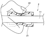
挿入部把持グリップ2は、医療行為情報検出部の1つである。挿入部把持グリップ2は、第1の医師である例えば大腸内視鏡検査の経験の浅い医師(以下、下位ドクターと記載する)104が手技を担当するときに使用される。挿入部把持グリップ2は、第1の操作装置であり、図2に示すようにグリップ本体21と、複数の圧力センサー22と、信号線23とを備えて構成されている。信号線23は、グリップ本体21から延出され、図1に示すように判定制御装置7に接続されている。
The insertion part grip grip 2 is one of medical practice information detection parts. The insertion portion grip grip 2 is used when a first doctor, for example, a doctor who has little experience in colonoscopy (hereinafter referred to as a lower doctor) 104 is in charge of the procedure. The insertion portion grip grip 2 is a first operating device, and includes a grip body 21, a plurality of pressure sensors 22, and a signal line 23 as shown in FIG. The signal line 23 extends from the grip body 21 and is connected to the determination control device 7 as shown in FIG.
グリップ本体21は、シリコンチューブ等、弾性を有する部材で管状に構成されている。グリップ本体21は、把持力の上昇に伴い変形し、把持力の減少により元の形状に復元される。グリップ本体21は、挿入部11の外周側に装着される。
The grip body 21 is formed in a tubular shape with an elastic member such as a silicon tube. The grip body 21 is deformed as the gripping force increases, and is restored to its original shape as the gripping force decreases. The grip body 21 is attached to the outer peripheral side of the insertion portion 11.
圧力センサー22は、グリップ本体21の外周周方向に複数配列される。圧力センサー22は、術者側圧力センサーであって、操作情報検出部である。圧力センサー22は、医療行為情報である操作入力情報として術者の挿入部把持力を検出する。具体的に、術者側圧力センサー22は、図3に示すように術者が挿入部11を把持することによって、その術者の把持力を挿入部把持グリップ2のグリップ本体21を介して検出する。術者側圧力センサー22の検出値は、信号線23を介して判定制御装置7に出力される。
A plurality of pressure sensors 22 are arranged in the outer circumferential direction of the grip body 21. The pressure sensor 22 is an operator side pressure sensor and is an operation information detection unit. The pressure sensor 22 detects the operator's insertion portion gripping force as operation input information that is medical practice information. Specifically, the operator-side pressure sensor 22 detects the operator's gripping force via the grip body 21 of the insertion portion grip grip 2 when the operator grips the insertion portion 11 as shown in FIG. To do. The detection value of the operator side pressure sensor 22 is output to the determination control device 7 via the signal line 23.
コントローラー3は、第2の医師であって熟練技術を有する医師(以下、上位ドクターと記載する)103が例えば下位ドクター104の手技に立ち会う際に使用する。図1に示すようにコントローラー3は、第2の操作装置である。コントローラー3は、例えば略円柱形状で、硬質な本体部31と、本体部31の基端側に連設されたグリップ部32と、信号線33とを備えて構成されている。グリップ部32は、把持性を考慮して例えば弾性部材で構成されている。信号線33は、例えば本体部31から延出されて判定制御装置7に接続される。
The controller 3 is used when a doctor (hereinafter, referred to as “upper doctor”) 103 who is a second doctor and has skillful techniques attends the procedure of the lower doctor 104, for example. As shown in FIG. 1, the controller 3 is a second operating device. The controller 3 has, for example, a substantially cylindrical shape, and includes a hard main body 31, a grip portion 32 that is connected to the base end side of the main body 31, and a signal line 33. The grip portion 32 is made of, for example, an elastic member in consideration of gripping properties. For example, the signal line 33 extends from the main body 31 and is connected to the determination control device 7.
本体部31は、所定位置に手動操作部34を備えている。手動操作部34には、いわゆる傾倒操作可能なジョイスティックタイプの操作レバー35が設けられている。本実施形態において、操作レバー35は、操作者が把持した状態で、本体部31の先端側と基端側とに傾倒操作可能な原点復帰型のスイッチである。なお、操作レバー35は、操作者が把持した状態で、該操作者から見て右側と左側とに傾倒操作可能な原点復帰型のスイッチであってもよい。
The main body 31 includes a manual operation unit 34 at a predetermined position. The manual operation unit 34 is provided with a joystick-type operation lever 35 that can be tilted. In the present embodiment, the operation lever 35 is an origin return type switch that can be tilted to the distal end side and the proximal end side of the main body 31 while being held by the operator. The operation lever 35 may be a return-to-origin switch that can be tilted to the right side and the left side as viewed from the operator while being held by the operator.
手動操作部34は、操作レバー35の頭部を先端側、または基端側に傾倒操作することにより制御指示信号を出力する構成になっている。コントローラー3は、操作レバー35の頭部を先端側に傾けると、挿入部11を前進させる制御信号と操作指示とを有する制御指示信号を出力する。一方コントローラー3は、操作レバー35の頭部を基端側に傾けると、挿入部11を後退させる制御信号と操作指示とを有する制御指示信号を出力する。
The manual operation unit 34 is configured to output a control instruction signal by tilting the head of the operation lever 35 toward the distal end side or the proximal end side. When the controller 3 tilts the head of the operation lever 35 toward the tip, the controller 3 outputs a control instruction signal having a control signal for moving the insertion portion 11 forward and an operation instruction. On the other hand, when the controller 3 tilts the head of the operation lever 35 toward the base end side, the controller 3 outputs a control instruction signal having a control signal for retracting the insertion portion 11 and an operation instruction.
本実施形態において、操作レバー35の傾倒角度の違いによって、挿入部11の進退速度が変化するように設定されている。すなわち、コントローラー3は、操作レバー35の傾倒角度が小さいとき、前進速度或いは後退速度を低速にする制御指示信号を出力する。そして、コントローラー3は、操作レバー35の傾倒角度が大きくなるにしたがって、速度を予め定めた挿入速度に設定する制御指示信号を出力する。
In the present embodiment, the advance / retreat speed of the insertion portion 11 is set to change depending on the tilt angle of the operation lever 35. That is, the controller 3 outputs a control instruction signal for decreasing the forward speed or the reverse speed when the tilt angle of the operation lever 35 is small. Then, the controller 3 outputs a control instruction signal for setting the speed to a predetermined insertion speed as the tilt angle of the operation lever 35 increases.
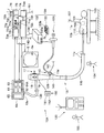
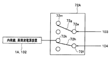
肛門装着具4は、図4に示すようにガイドチューブ40と、挿入部進退装置50とを備えて構成されている。
ガイドチューブ40は、医療行為情報検出部の1つであり、チューブ本体41と、少なくとも1つの圧力センサー42と、信号線43とを備えて構成されている。信号線43は、チューブ本体41から延出されて、図1に示すように判定制御装置7に接続されている。 As shown in FIG. 4, the anus fitting 4 includes aguide tube 40 and an insertion portion advancing / retreating device 50.
Theguide tube 40 is one of medical practice information detection units, and includes a tube body 41, at least one pressure sensor 42, and a signal line 43. The signal line 43 extends from the tube main body 41 and is connected to the determination control device 7 as shown in FIG.
ガイドチューブ40は、医療行為情報検出部の1つであり、チューブ本体41と、少なくとも1つの圧力センサー42と、信号線43とを備えて構成されている。信号線43は、チューブ本体41から延出されて、図1に示すように判定制御装置7に接続されている。 As shown in FIG. 4, the anus fitting 4 includes a
The
チューブ本体41は、挿入部11が挿通可能な貫通孔を備えている。チューブ本体41は、シリコンチューブ等の弾性を有する管状部材で構成されている。チューブ本体41は、患者101の肛門102に設置される。
圧力センサー42は、チューブ本体41の外周に設けられている。圧力センサー42は、患者側圧力センサーであって、生体情報を取得する生体情報検出部である。圧力センサー42は、医療行為情報である患者の肛門収縮力を検出する。具体的に、ガイドチューブ40は、患者側圧力センサー42によって肛門収縮力を確実に検出できるように、医師、或いは医療関係者によって図4に示すように患者101の肛門102の所定位置に配置される。患者側圧力センサー42の検出値は、信号線43を介して判定制御装置7に出力される。 Thetube body 41 includes a through hole through which the insertion portion 11 can be inserted. The tube body 41 is composed of a tubular member having elasticity such as a silicon tube. The tube body 41 is installed in the anus 102 of the patient 101.
Thepressure sensor 42 is provided on the outer periphery of the tube main body 41. The pressure sensor 42 is a patient-side pressure sensor and is a biological information detection unit that acquires biological information. The pressure sensor 42 detects the anal contraction force of the patient, which is medical practice information. Specifically, the guide tube 40 is disposed at a predetermined position of the anus 102 of the patient 101 as shown in FIG. 4 by a doctor or a medical person so that the anal contraction force can be reliably detected by the patient-side pressure sensor 42. The The detection value of the patient side pressure sensor 42 is output to the determination control device 7 via the signal line 43.
圧力センサー42は、チューブ本体41の外周に設けられている。圧力センサー42は、患者側圧力センサーであって、生体情報を取得する生体情報検出部である。圧力センサー42は、医療行為情報である患者の肛門収縮力を検出する。具体的に、ガイドチューブ40は、患者側圧力センサー42によって肛門収縮力を確実に検出できるように、医師、或いは医療関係者によって図4に示すように患者101の肛門102の所定位置に配置される。患者側圧力センサー42の検出値は、信号線43を介して判定制御装置7に出力される。 The
The
挿入部進退装置50は、図4、図5に示すようにガイドチューブ40の基端側に配設される。本実施形態においては、チューブ本体41の端部が、連結部51aに取り付けられている。
The insertion portion advancing / retreating device 50 is disposed on the proximal end side of the guide tube 40 as shown in FIGS. In the present embodiment, the end of the tube main body 41 is attached to the connecting portion 51a.
挿入部進退装置50は、医療機器制御装置及び挿入部移動量検出装置を兼ねる。挿入部進退装置50は、箱体51の内部空間に、2つの回動自在なローラー52、53を備えている。箱体51は、その対向する面の一面側に挿入部11を挿入するための挿入部挿入口54を備えている。箱体51の他面側には、連結部51aが形成されている。連結部51aは、箱体51の内部と外部とを連通する連通孔を備えている。挿入部挿入口54から箱体51内に導入された挿入部11は、連通孔から外部に導出されるようになっている。
The insertion portion advance / retreat apparatus 50 also serves as a medical device control device and an insertion portion movement amount detection device. The insertion portion advancing / retracting device 50 includes two rotatable rollers 52 and 53 in the internal space of the box 51. The box 51 includes an insertion portion insertion port 54 for inserting the insertion portion 11 on one surface side of the opposing surface. A connecting portion 51 a is formed on the other surface side of the box 51. The connecting portion 51 a includes a communication hole that allows the inside and the outside of the box body 51 to communicate with each other. The insertion part 11 introduced into the box 51 from the insertion part insertion port 54 is led out to the outside from the communication hole.
2つのローラー52、53は、それぞれ弾性を有する樹脂部材、或いはゴム部材で形成されている。ローラー52は、回転軸52Aに一体的に固定されている。ローラー53は、回転軸53Aに一体的に固定されている。挿入部挿入口54から挿入された挿入部11は、その外面をローラー52、53によって押圧された状態で、ローラー52、53間に挟持して配置される。
The two rollers 52 and 53 are each formed of an elastic resin member or rubber member. The roller 52 is integrally fixed to the rotation shaft 52A. The roller 53 is integrally fixed to the rotation shaft 53A. The insertion part 11 inserted from the insertion part insertion port 54 is disposed so as to be sandwiched between the rollers 52 and 53 with its outer surface being pressed by the rollers 52 and 53.
回転軸52Aは駆動軸である。回転軸52Aの一端部は、クラッチ56を介して箱体51の外部に配設されたモーター55に連結されている。従って、ローラー52は、モーター55の駆動力によって時計回り、或いは反時計回りに回転する状態と、挿入部11の移動に伴って回転する状態とに切り換えられるようになっている。なお、ローラー52、53間に押圧して挟持された挿入部11は、モーター55の駆動力によるローラー52の回転に伴って、前進、または後退する構成になっている。
The rotary shaft 52A is a drive shaft. One end of the rotary shaft 52A is connected to a motor 55 disposed outside the box 51 via a clutch 56. Accordingly, the roller 52 can be switched between a state in which the roller 52 rotates clockwise or counterclockwise by the driving force of the motor 55 and a state in which the roller 52 rotates in accordance with the movement of the insertion portion 11. Note that the insertion portion 11 pressed and sandwiched between the rollers 52 and 53 is configured to move forward or backward as the roller 52 is rotated by the driving force of the motor 55.
回転軸53Aは従動軸である。回転軸53Aの一端部は、箱体51の外部に配設されたエンコーダー57に配設されている。エンコーダー57は、駆動状態検出部である。エンコーダー57は、医療行為情報検出部の1つである。エンコーダー57は、回転軸53Aの回転量から、医療行為情報の1つである挿入部進退装置50の駆動によるパラメーターとして可撓管部11cの移動量を検出する。エンコーダー57の検出値は、挿入部移動量として信号線57aを介して判定制御装置7に出力される。
なお、符号55aは、モーター用信号線である。符号56aは、クラッチ用信号線である。それぞれの信号線55a、56aは、判定制御装置7に接続されている。 Therotating shaft 53A is a driven shaft. One end of the rotating shaft 53A is disposed in an encoder 57 disposed outside the box 51. The encoder 57 is a drive state detection unit. The encoder 57 is one of medical practice information detection units. The encoder 57 detects the amount of movement of the flexible tube portion 11c from the amount of rotation of the rotation shaft 53A as a parameter by driving the insertion portion advancing / retreating device 50, which is one piece of medical practice information. The detection value of the encoder 57 is output to the determination control device 7 through the signal line 57a as the insertion portion movement amount.
Reference numeral 55a denotes a motor signal line. Reference numeral 56a denotes a clutch signal line. Each of the signal lines 55 a and 56 a is connected to the determination control device 7.
なお、符号55aは、モーター用信号線である。符号56aは、クラッチ用信号線である。それぞれの信号線55a、56aは、判定制御装置7に接続されている。 The
また、本実施形態において、患者側圧力センサー42から延出する信号線43、モーター用信号線55a、クラッチ用信号線56a、及びエンコーダー用信号線57aは、信号線ケーブル58内に一纏めに挿通されている。
In the present embodiment, the signal line 43, the motor signal line 55 a, the clutch signal line 56 a, and the encoder signal line 57 a extending from the patient-side pressure sensor 42 are collectively inserted into the signal line cable 58. ing.
本実施形態において、内視鏡1の挿入部11は、挿入部進退装置50のローラー52、53間、ガイドチューブ40の貫通孔を介して大腸内に挿入される。したがって、挿入部11が大腸に挿入されていくとき、可撓管部11cの移動に伴ってローラー53が回転する。このとき、エンコーダー57は、ローラー53の回転と共に回転する回転軸53Aの回転量を、可撓管部11cの移動量として検出する。
In the present embodiment, the insertion portion 11 of the endoscope 1 is inserted into the large intestine between the rollers 52 and 53 of the insertion portion advance / retreat apparatus 50 and the through hole of the guide tube 40. Therefore, when the insertion portion 11 is inserted into the large intestine, the roller 53 rotates with the movement of the flexible tube portion 11c. At this time, the encoder 57 detects the amount of rotation of the rotating shaft 53A that rotates with the rotation of the roller 53 as the amount of movement of the flexible tube portion 11c.
一方、挿入部進退装置50のモーター55は、判定制御装置7から挿入部進退装置50に制御信号が出力されることによって駆動する。モーター55が駆動することにより、駆動軸である回転軸52Aに固定されているローラー52が回転する。すると、ローラー52、53の間に挟持されている挿入部11が前進、或いは後退動作する。挿入部11の前進量、或いは後退量、すなわち挿入部移動量は、エンコーダー57によって検出される。
On the other hand, the motor 55 of the insertion unit advancing / retreating device 50 is driven by a control signal output from the determination control device 7 to the insertion unit advancing / retreating device 50. When the motor 55 is driven, the roller 52 fixed to the rotation shaft 52A that is a drive shaft rotates. Then, the insertion part 11 clamped between the rollers 52 and 53 moves forward or backward. The amount of advance or retreat of the insertion portion 11, that is, the amount of movement of the insertion portion is detected by the encoder 57.
内視鏡制御装置6には、内視鏡1及び判定制御装置7が接続される。内視鏡制御装置6は、その内部にCPUを備えた制御部61と、記憶部である例えばハードディスク等の記憶装置62と、信号処理部63と、演算処理部64等とを備えて主に構成されている。符号65は光源部であり、体腔内を照明する照明光の照明状態を制御する。
The endoscope 1 and the determination controller 7 are connected to the endoscope controller 6. The endoscope control device 6 mainly includes a control unit 61 having a CPU therein, a storage device 62 such as a hard disk as a storage unit, a signal processing unit 63, an arithmetic processing unit 64, and the like. It is configured. Reference numeral 65 denotes a light source unit that controls the illumination state of illumination light that illuminates the body cavity.
記憶装置62には、判定制御装置7の判定に用いる基準情報として各種閾値が登録される。本実施形態において、記憶装置62には、肛門収縮力の閾値及び挿入部把持力の閾値が登録される。これら閾値は、判定制御装置7に出力されるようになっている。
In the storage device 62, various threshold values are registered as reference information used for determination by the determination control device 7. In the present embodiment, the storage device 62 registers a threshold value for anal contraction force and a threshold value for insertion portion gripping force. These threshold values are output to the determination control device 7.
挿入部把持力の閾値は、下位ドクター104の握力を基準に設定される。肛門収縮力の閾値は、患者の身体的特徴、下位ドクター104の技術レベル等を考慮して適宜設定される。身体的特徴とは、年齢、性別、健康状態等である。そして、各閾値は、上位ドクター103によって記憶装置62に登録される。
The threshold value of the insertion portion gripping force is set based on the gripping force of the lower doctor 104. The threshold value of the anal contraction force is appropriately set in consideration of the physical characteristics of the patient, the technical level of the lower doctor 104, and the like. Physical characteristics include age, sex, health status, and the like. Each threshold value is registered in the storage device 62 by the higher-level doctor 103.
信号処理部63は、内視鏡1に備えられている撮像素子を駆動する制御信号、及び撮像素子から伝送される電気信号から映像信号を生成する信号処理等を行う。信号処理部63で生成された映像信号は、判定制御装置7を介して内視鏡用モニター5の画面5aに出力されるようになっている。画面5a上に表示される内視鏡画像は、上位ドクター103及び下位ドクター104によって観察される。
The signal processing unit 63 performs signal processing for generating a video signal from a control signal for driving the image sensor provided in the endoscope 1 and an electric signal transmitted from the image sensor. The video signal generated by the signal processing unit 63 is output to the screen 5 a of the endoscope monitor 5 via the determination control device 7. The endoscopic image displayed on the screen 5 a is observed by the upper doctor 103 and the lower doctor 104.
演算処理部64は、医療行為情報検出部の1つである。演算処理部64は、信号処理部63で生成された映像信号を基に、医療行為情報の1つである下位ドクター104による実際の操作結果である先端部の進退移動量を計測する。演算処理部64によって算出される進退移動量とは、先端部11aの体内における移動量である。先端部11aの移動量は、現在の内視鏡画像と、所定時間前の内視鏡画像とを比較して計測される移動量であり、先端部移動量として判定制御装置7に出力される。
The arithmetic processing unit 64 is one of medical practice information detection units. Based on the video signal generated by the signal processing unit 63, the arithmetic processing unit 64 measures the amount of forward / backward movement of the distal end as an actual operation result by the lower doctor 104, which is one of medical practice information. The forward / backward movement amount calculated by the arithmetic processing unit 64 is the movement amount of the distal end portion 11a in the body. The movement amount of the distal end portion 11a is a movement amount measured by comparing the current endoscopic image and an endoscope image before a predetermined time, and is output to the determination control device 7 as the distal end portion movement amount. .
図1に示すように判定制御装置7は、判定部71と、信号出力切換部72と、信号/情報変換部73と、制御指示部74とを備えた切換信号発生装置である。
判定部71には、患者側圧力センサー42によって検出された肛門収縮力の値、内視鏡画像から計測した先端部移動量、エンコーダー57によって検出された挿入部移動量、及び術者側圧力センサー22によって検出された挿入部把持力の値等の各種医療行為情報がそれぞれ入力されるようになっている。また、判定部71には、医療行為情報閾値である、記憶装置62に登録されている肛門収縮力の閾値及び挿入部把持力の閾値が入力されるようになっている。 As shown in FIG. 1, the determination control device 7 is a switching signal generation device including adetermination unit 71, a signal output switching unit 72, a signal / information conversion unit 73, and a control instruction unit 74.
Thedetermination unit 71 includes the value of the anal contraction force detected by the patient-side pressure sensor 42, the distal-end movement amount measured from the endoscopic image, the insertion-portion movement amount detected by the encoder 57, and the operator-side pressure sensor. Various medical practice information such as the value of the insertion portion gripping force detected by 22 is input. Further, the threshold value of the anal contraction force and the threshold value of the insertion portion gripping force registered in the storage device 62, which are medical practice information threshold values, are input to the determination unit 71.
判定部71には、患者側圧力センサー42によって検出された肛門収縮力の値、内視鏡画像から計測した先端部移動量、エンコーダー57によって検出された挿入部移動量、及び術者側圧力センサー22によって検出された挿入部把持力の値等の各種医療行為情報がそれぞれ入力されるようになっている。また、判定部71には、医療行為情報閾値である、記憶装置62に登録されている肛門収縮力の閾値及び挿入部把持力の閾値が入力されるようになっている。 As shown in FIG. 1, the determination control device 7 is a switching signal generation device including a
The
判定部71は、各値が入力されると、肛門収縮力の値とその閾値との比較、先端部移動量の値と挿入部移動量の値との比較、挿入部把持力の値とその閾値との比較を行う。
When each value is input, the determination unit 71 compares the value of the anal contraction force and its threshold value, compares the value of the distal end portion movement amount and the value of the insertion portion movement amount, and determines the value of the insertion portion gripping force and its value. Compare with threshold.
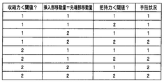
そして、判定部71は、肛門収縮力の閾値と患者側圧力センサー42によって検出された肛門収縮力との比較を行って、患者への負担の有無を判定する。すなわち、図6に示すように患者側圧力センサー42が検出した肛門収縮力が、その閾値より小さな場合には患者状態が良好(図中記号「1」)であると判定し、その閾値より大きな場合には患者負担発生(図中記号「2」)と判定する。
Then, the determination unit 71 compares the threshold value of the anal contraction force with the anal contraction force detected by the patient-side pressure sensor 42 to determine whether or not there is a burden on the patient. That is, as shown in FIG. 6, when the anal contraction force detected by the patient-side pressure sensor 42 is smaller than the threshold value, it is determined that the patient condition is good (symbol “1” in the figure), and is larger than the threshold value. In this case, it is determined that the patient burden has occurred (symbol “2” in the figure).
また、判定部71は、先端部移動量と挿入部挿入量とが一致しているか否かを判定して、挿入部がスムーズに体内に導入されているか否かを判定する。すなわち、図6に示すように先端部移動量と挿入部挿入量とが一致した場合には、挿入部11がスムーズに体内に挿入されている(図中記号「1」)と判定し、先端部移動量と挿入部挿入量とが異なる場合、具体的には挿入部挿入量に比べて先端部移動量が少ない場合、先端部11aが壁に引っかかっている、或いはループがきつい等のために挿入に手間取っている(図中記号「2」)と判定する。
Further, the determination unit 71 determines whether or not the distal end portion movement amount and the insertion portion insertion amount are the same, and determines whether or not the insertion portion is smoothly introduced into the body. That is, as shown in FIG. 6, when the distal end movement amount and the insertion portion insertion amount coincide with each other, it is determined that the insertion portion 11 is smoothly inserted into the body (symbol “1” in the figure), and the distal end When the amount of movement of the part is different from the amount of insertion of the insertion part, specifically, when the amount of movement of the tip part is smaller than the amount of insertion of the insertion part, the tip part 11a is caught on the wall, or the loop is tight It is determined that it takes time to insert (symbol “2” in the figure).
また、判定部71は、挿入部把持力の閾値と術者側圧力センサー22によって検出された挿入部把持力との比較を行って、術者の挿入手技が順調であるか否かを判定する。すなわち、図6に示すように術者側圧力センサー22が検出した挿入部把持力が、その閾値より小さい場合、挿入手技が順調に行われている(図中記号「1」)と判定し、その閾値より大きい場合には挿入部11の挿入に手間取って力が入りすぎている(図中記号「2」)と判定する。
The determination unit 71 compares the insertion unit gripping force threshold value with the insertion unit gripping force detected by the operator-side pressure sensor 22 to determine whether or not the operator's insertion procedure is smooth. . That is, as shown in FIG. 6, when the insertion portion gripping force detected by the operator-side pressure sensor 22 is smaller than the threshold value, it is determined that the insertion procedure has been performed smoothly (symbol “1” in the figure), If it is larger than the threshold, it is determined that too much force is applied to insert the insertion portion 11 (symbol “2” in the figure).
次に、信号出力切換部72について説明する。
信号出力切換部72は、入力部72aと、切換部72bと、第1出力部72cと、第2出力部72dとを備える。
入力部72aには、コントローラー3から出力される制御指示信号が入力される。切換部72bは、入力部72aに入力された制御指示信号の出力先を、第1出力部72c、或いは第2出力部72dに切り換えるいわゆるスイッチである。切換部72bは、制御指示部74から出力される後述する切換信号に基づいて出力先が切り換えられるようになっている。 Next, the signaloutput switching unit 72 will be described.
The signaloutput switching unit 72 includes an input unit 72a, a switching unit 72b, a first output unit 72c, and a second output unit 72d.
A control instruction signal output from thecontroller 3 is input to the input unit 72a. The switching unit 72b is a so-called switch that switches the output destination of the control instruction signal input to the input unit 72a to the first output unit 72c or the second output unit 72d. The switching unit 72b is configured to switch the output destination based on a switching signal (described later) output from the control instruction unit 74.
信号出力切換部72は、入力部72aと、切換部72bと、第1出力部72cと、第2出力部72dとを備える。
入力部72aには、コントローラー3から出力される制御指示信号が入力される。切換部72bは、入力部72aに入力された制御指示信号の出力先を、第1出力部72c、或いは第2出力部72dに切り換えるいわゆるスイッチである。切換部72bは、制御指示部74から出力される後述する切換信号に基づいて出力先が切り換えられるようになっている。 Next, the signal
The signal
A control instruction signal output from the
第1出力部72cは、信号/情報変換部73に接続されており、切換部72bを介して伝送された制御指示信号を信号/情報変換部73に出力する。一方、第2出力部72dは、挿入部進退装置50に接続されており、切換部72bを介して伝送された制御指示信号をモーター55に出力する。
The first output unit 72c is connected to the signal / information conversion unit 73 and outputs the control instruction signal transmitted through the switching unit 72b to the signal / information conversion unit 73. On the other hand, the second output unit 72d is connected to the insertion unit advance / retreat apparatus 50, and outputs the control instruction signal transmitted via the switching unit 72b to the motor 55.
信号/情報変換部73には、内視鏡制御装置6から出力される映像信号、コントローラー3から出力される制御指示信号、及び判定部71に入力された各種医療行為情報が入力される。
信号/情報変換部73に入力された患者側圧力センサー42によって検出された肛門収縮力の値、内視鏡画像から計測された先端部移動量、エンコーダー57によって検出された挿入部移動量、及び術者側圧力センサー22によって検出された挿入部把持力の値は、リアルタイムで、検出モニター8に出力される。 The signal / information conversion unit 73 receives a video signal output from theendoscope control device 6, a control instruction signal output from the controller 3, and various medical practice information input to the determination unit 71.
The value of the anal contraction force detected by the patient-side pressure sensor 42 input to the signal / information conversion unit 73, the distal end portion movement amount measured from the endoscopic image, the insertion portion movement amount detected by the encoder 57, and The value of the insertion portion gripping force detected by the operator side pressure sensor 22 is output to the detection monitor 8 in real time.
信号/情報変換部73に入力された患者側圧力センサー42によって検出された肛門収縮力の値、内視鏡画像から計測された先端部移動量、エンコーダー57によって検出された挿入部移動量、及び術者側圧力センサー22によって検出された挿入部把持力の値は、リアルタイムで、検出モニター8に出力される。 The signal / information conversion unit 73 receives a video signal output from the
The value of the anal contraction force detected by the patient-
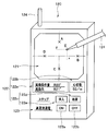
検出モニター8は、上位ドクター103が下位ドクター104の挿入手技の状況を把握する際に観察する表示装置である。図7に示すように検出モニター8の情報表示部である画面8a上には、例えば下位ドクター操作情報を表示する把持力表示エリア81、患者情報を表示する括約筋収縮力エリア82、医療機器操作情報を表示する前進量エリア83、医療機器操作情報を表示する挿入長エリア84を有している。
The detection monitor 8 is a display device that is observed when the upper doctor 103 grasps the state of the insertion procedure of the lower doctor 104. As shown in FIG. 7, on a screen 8a which is an information display section of the detection monitor 8, for example, a gripping force display area 81 for displaying lower doctor operation information, a sphincter contraction force area 82 for displaying patient information, and medical device operation information Has an advance amount area 83, and an insertion length area 84 for displaying medical device operation information.
画面8a上の把持力表示エリア81には、挿入部把持力の値が例えば棒グラフ状に表示される。一方、肛門収縮力の値は、括約筋収縮力エリア82に例えば時系列的な折れ線グラフとして表示される。先端部移動量は、前進量エリア83に単位時間当たりの移動量として例えば時系列的な折れ線グラフと表示される。挿入部移動量は、挿入長エリア84に単位時間当たりの移動量として例えば時系列的な折れ線グラフとして表示される。挿入部移動量を計測する単位時間とは、先端部移動量を計測する場合の現在の内視鏡画像と所定時間前の内視鏡画像とを比較計測するときの所定時間と同時間である。
In the gripping force display area 81 on the screen 8a, the value of the insertion portion gripping force is displayed in a bar graph shape, for example. On the other hand, the value of the anal contractile force is displayed in the sphincter contractile force area 82 as, for example, a time-series line graph. The tip end movement amount is displayed in the advance amount area 83 as a movement amount per unit time, for example, as a time-series line graph. The insertion portion movement amount is displayed in the insertion length area 84 as a movement amount per unit time, for example, as a time-series line graph. The unit time for measuring the insertion portion movement amount is the same time as the predetermined time when the current endoscope image when measuring the distal end portion movement amount and the endoscope image before the predetermined time are compared and measured. .
なお、本実施形態においては、取得した医療行為情報を棒グラフ、折れ線グラフで表示するとしている。しかし、取得した医療行為情報を、具体的な数値でエリア上に表示するようにしても良い。また、検出モニター8に、把持力表示エリア81、括約筋収縮力エリア82、前進量エリア83、挿入長エリア84に加えて、前記図6に示した判定部71の判定結果を表示する判定結果表示エリア、或いは内視鏡画像を表示する内視鏡画像用エリア等を設けるようにしてもよい。
In the present embodiment, the acquired medical practice information is displayed as a bar graph or a line graph. However, the acquired medical practice information may be displayed on the area with specific numerical values. In addition to the gripping force display area 81, the sphincter contraction force area 82, the advance amount area 83, and the insertion length area 84, a determination result display for displaying the determination result of the determination unit 71 shown in FIG. An area, an endoscope image area for displaying an endoscope image, or the like may be provided.
信号/情報変換部73に入力された映像信号は、内視鏡用モニター5に出力され、画面5a上に内視鏡画像として表示される。
The video signal input to the signal / information converter 73 is output to the endoscope monitor 5 and displayed as an endoscopic image on the screen 5a.
コントローラー3の制御指示信号は、信号/情報変換部73に入力されると文字情報に変換されて、内視鏡用モニター5の画面5a上に内視鏡画像とともに表示される。すなわち、上位ドクター103が、例えば操作レバー35を先端側に略15度、傾ける操作を行った場合、信号/情報変換部73は、入力される制御指示信号から予め設定された「挿入部を慎重に進めなさい」という操作指示を内視鏡用モニター5に出力する。このことによって、画面5aの所定位置に操作指示が表示される。
When the control instruction signal of the controller 3 is input to the signal / information conversion unit 73, it is converted into character information and displayed on the screen 5a of the endoscope monitor 5 together with the endoscope image. That is, when the upper doctor 103 performs an operation of tilting the operation lever 35 to the distal end side by about 15 degrees, for example, the signal / information conversion unit 73 reads the “insertion unit carefully from a preset control instruction signal. The operation instruction “Proceed to” is output to the endoscope monitor 5. As a result, an operation instruction is displayed at a predetermined position on the screen 5a.
なお、画面5aに表示される操作指示は、上述の指示に限定されるものではなく、各種操作指示が画面5a上に表示されるようになっている。操作指示としては、例えば、上位ドクター103が、操作レバー35を基端側に略15度傾ける操作を行っていた場合の「挿入部を慎重に後退させなさい」という操作指示、或いは上位ドクター103が、操作レバー35を先端側に45度傾ける操作を行っていた場合の「挿入部を進めなさい」という操作指示、或いは上位ドクター103が、操作レバー35を一方向に傾けていた状態から他方向、すなわち逆方向に傾けた場合の「挿入停止」という操作指示、或いは上位ドクター103が、操作レバー35を操作していない場合、或いは傾倒状態から手を離して直立状態に切り換えられた場合の「手技を続けなさい」という操作指示等がある。
Note that the operation instructions displayed on the screen 5a are not limited to the above-described instructions, and various operation instructions are displayed on the screen 5a. As an operation instruction, for example, when the upper doctor 103 is performing an operation of tilting the operation lever 35 to the proximal end side by approximately 15 degrees, an operation instruction “retreat the insertion portion carefully” or the upper doctor 103 When the operation lever 35 is tilted 45 degrees toward the distal end, the operation instruction “Proceed with the insertion section” or the upper doctor 103 tilts the operation lever 35 in one direction to the other direction. That is, an operation instruction “stop insertion” when tilted in the opposite direction, or “procedure” when the upper doctor 103 is not operating the operation lever 35 or when the operator is released from the tilted state and switched to the upright state. There is an operation instruction or the like.
制御指示部74は、判定部71の各判定結果を基に、下位ドクターの手技状況を判定し、その判定結果に対応する切換信号を信号出力切換部72に出力する。
すなわち、制御指示部74は、判定結果の組み合わせを確認して、図6に示すように判定部71のすべての判定結果が「1」であった場合、下位ドクター104による手技が順調(図中手技状況記号「1」)に進んでいると判定する。一方、制御指示部74は、判定部71のすべての判定結果が「2」であった場合、下位ドクター104による手技が不安定(図中手技状況記号「2」)であると判定する。また、制御指示部74は、図6に示すように判定結果のうち2つが「1」で、判定結果の1つが「2」であった場合には下位ドクター104の手技が順調であると判定し、判定結果のうち1つが「1」で、判定結果の2つが「2」であった場合、下位ドクター104の手技が不安定であると判定する。 Based on each determination result of thedetermination unit 71, the control instruction unit 74 determines the procedure status of the lower doctor, and outputs a switching signal corresponding to the determination result to the signal output switching unit 72.
In other words, thecontrol instruction unit 74 confirms the combination of the determination results, and if all the determination results of the determination unit 71 are “1” as shown in FIG. It is determined that the procedure progresses to the procedure status symbol “1”). On the other hand, when all the determination results of the determination unit 71 are “2”, the control instruction unit 74 determines that the procedure by the lower doctor 104 is unstable (the procedure status symbol “2” in the figure). Further, as shown in FIG. 6, the control instruction unit 74 determines that the procedure of the lower doctor 104 is smooth when two of the determination results are “1” and one of the determination results is “2”. If one of the determination results is “1” and two of the determination results are “2”, it is determined that the technique of the lower doctor 104 is unstable.
すなわち、制御指示部74は、判定結果の組み合わせを確認して、図6に示すように判定部71のすべての判定結果が「1」であった場合、下位ドクター104による手技が順調(図中手技状況記号「1」)に進んでいると判定する。一方、制御指示部74は、判定部71のすべての判定結果が「2」であった場合、下位ドクター104による手技が不安定(図中手技状況記号「2」)であると判定する。また、制御指示部74は、図6に示すように判定結果のうち2つが「1」で、判定結果の1つが「2」であった場合には下位ドクター104の手技が順調であると判定し、判定結果のうち1つが「1」で、判定結果の2つが「2」であった場合、下位ドクター104の手技が不安定であると判定する。 Based on each determination result of the
In other words, the
そして、制御指示部74は、手技状況を順調と判定した場合、信号出力切換部72に第1切換信号を出力する。すると、切換部72bは、第1出力部72cに接続される。このことによって、コントローラー3の制御指示信号は、入力部72aに入力された後、信号/情報変換部73に出力される。
And the control instruction | indication part 74 outputs a 1st switching signal to the signal output switching part 72, when it determines with a procedure condition being smooth. Then, the switching unit 72b is connected to the first output unit 72c. As a result, the control instruction signal of the controller 3 is input to the input unit 72 a and then output to the signal / information conversion unit 73.
一方、制御指示部74は、手技状況を不安定と判定した場合、信号出力切換部72に第2切換信号を出力する。すると、切換部72bは、第2出力部72dに接続される。このことによって、コントローラー3の制御指示信号は、入力部72aに入力された後、挿入部進退装置50に出力される。すると、挿入部進退装置50のモーター55のクラッチ56がつながれ、その後、モーター55の駆動が開始されて、ローラー52の回転に伴って挿入部11が進退する。このとき、画面5a上には「ここから、上位ドクターが操作を行います」等のコメントを表示して、下位ドクター104に上位ドクター103による操作に切り換えられたことを告知する。
On the other hand, the control instruction unit 74 outputs a second switching signal to the signal output switching unit 72 when the procedure status is determined to be unstable. Then, the switching unit 72b is connected to the second output unit 72d. Thus, the control instruction signal of the controller 3 is input to the input unit 72a and then output to the insertion unit advance / retreat apparatus 50. Then, the clutch 56 of the motor 55 of the insertion portion advancing / retreating device 50 is engaged, and then the driving of the motor 55 is started, so that the insertion portion 11 advances and retreats as the roller 52 rotates. At this time, a comment such as “From here, the upper doctor will operate” is displayed on the screen 5 a to notify the lower doctor 104 that the operation has been switched to the operation by the upper doctor 103.
なお、本実施形態において、判定制御装置7と挿入部把持グリップ2との接続を信号線23によって行い、判定制御装置7とコントローラー3との接続を信号線33によって行う等、各装置間の接続をいわゆる有線式としている。しかし、各装置間の接続は、有線式に限定されるものではなく、無線式で構成するようにしてもよい。
In addition, in this embodiment, the connection between each apparatus, such as connecting the determination control apparatus 7 and the insertion part grip grip 2 by the signal line 23, and connecting the determination control apparatus 7 and the controller 3 by the signal line 33, etc. Is a so-called wired type. However, the connection between the devices is not limited to the wired type, and may be configured to be a wireless type.
また、本実施形態においては、判定制御装置7と内視鏡制御装置6とを別体にした構成を示している。しかし、内視鏡制御装置6と判定制御装置7とを一体に構成するようにしてもよい。
In the present embodiment, a configuration in which the determination control device 7 and the endoscope control device 6 are separated is shown. However, the endoscope control device 6 and the determination control device 7 may be configured integrally.
上述のように構成した医療システム10を使用して大腸内視鏡検査を行う場合について説明する。
上位ドクター103と下位ドクター104とによって、大腸内視鏡検査を行うに当たって、上位ドクター103は、コントローラー3を把持し、モニター5の画面5a及びモニター8の画面8aを視認することが可能な位置に待機している。
一方、下位ドクター104は、肛門装着具4の配置状態、特にガイドチューブ40の設置位置等を確認する。そして、確認後、下位ドクター104による手技を開始する。 A case where a colonoscopy is performed using themedical system 10 configured as described above will be described.
When performing the colonoscopy with theupper doctor 103 and the lower doctor 104, the upper doctor 103 holds the controller 3 and is in a position where the screen 5a of the monitor 5 and the screen 8a of the monitor 8 can be visually recognized. Waiting.
On the other hand, thelower doctor 104 confirms the arrangement state of the anus fitting 4, particularly the installation position of the guide tube 40 and the like. Then, after confirmation, the procedure by the lower doctor 104 is started.
上位ドクター103と下位ドクター104とによって、大腸内視鏡検査を行うに当たって、上位ドクター103は、コントローラー3を把持し、モニター5の画面5a及びモニター8の画面8aを視認することが可能な位置に待機している。
一方、下位ドクター104は、肛門装着具4の配置状態、特にガイドチューブ40の設置位置等を確認する。そして、確認後、下位ドクター104による手技を開始する。 A case where a colonoscopy is performed using the
When performing the colonoscopy with the
On the other hand, the
まず、下位ドクター104は、挿入部把持グリップ2を挿入部11に装着する。また、下位ドクター104は、挿入部11の先端部11aを挿入部進退装置50の箱体51に形成されている挿入部挿入口54を介して箱体51内に挿入する。そして、下位ドクター104は、挿入部11をローラー52、53間に配置し、その先端部11aを連結部51aの貫通孔から導出させる。このことによって、挿入部11の先端部11aがチューブ本体41内に配置された状態になる。
First, the lower doctor 104 attaches the insertion portion grip grip 2 to the insertion portion 11. The lower doctor 104 inserts the distal end portion 11 a of the insertion portion 11 into the box body 51 through the insertion portion insertion port 54 formed in the box body 51 of the insertion portion advance / retreat apparatus 50. And the low-order doctor 104 arrange | positions the insertion part 11 between the rollers 52 and 53, and makes the front-end | tip part 11a derive | lead-out from the through-hole of the connection part 51a. As a result, the distal end portion 11 a of the insertion portion 11 is placed in the tube main body 41.
ここで、下位ドクター104による大腸内への挿入手技が開始される。すなわち、下位ドクター104は、挿入部11を挿入部把持グリップ2越しに把持する。そして、下位ドクター104は、画面5aに表示される上位ドクター103からの操作指示を確認し、その画面5aに表示された操作指示にしたがって手技を開始する。
Here, the insertion procedure into the large intestine by the lower doctor 104 is started. That is, the lower doctor 104 grips the insertion portion 11 through the insertion portion grip grip 2. Then, the lower doctor 104 confirms the operation instruction from the upper doctor 103 displayed on the screen 5a, and starts the procedure according to the operation instruction displayed on the screen 5a.
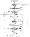
制御指示部74は、図8のステップS1に示すように判定部71の判定結果に基づいて下位ドクター104による挿入手技が順調であるか否かを判定するため、判定部71による判定結果の検討を開始し、ステップS2に進む。
The control instruction unit 74 examines the determination result by the determination unit 71 in order to determine whether or not the insertion procedure by the lower doctor 104 is smooth based on the determination result of the determination unit 71 as shown in step S1 of FIG. And proceed to step S2.
上位ドクター103は、コントローラー3を把持しつつ、画面5aに表示される内視鏡画像及び画面8aの各表示エリア81、82、83、84に表示される情報を確認して下位ドクター104の操作状況を把握する。
The upper doctor 103 confirms the endoscopic image displayed on the screen 5a and the information displayed in the display areas 81, 82, 83, and 84 of the screen 8a while holding the controller 3, and operates the lower doctor 104. Know the situation.
ステップS2において制御指示部74は、判定部71の判定結果に基づいて、手技が「順調」であるか「不安定」であるかを判定する。そして、制御指示部74は、その判定結果に対応する切換信号を信号出力切換部72に出力する。
制御指示部74は、手技開始直後にもかかわらず、「不安定」であると判定した場合、ステップS3に進み挿入手技を停止する。このとき、制御指示部74は、信号/情報変換部73を介して画面5aに例えば「確認をお願いします」等のコメントを表示して、確認を促す。 In step S <b> 2, thecontrol instruction unit 74 determines whether the procedure is “smooth” or “unstable” based on the determination result of the determination unit 71. Then, the control instruction unit 74 outputs a switching signal corresponding to the determination result to the signal output switching unit 72.
If thecontrol instruction unit 74 determines that the state is “unstable” immediately after the start of the procedure, the process proceeds to step S <b> 3 and stops the insertion procedure. At this time, the control instruction unit 74 displays a comment such as “please confirm” on the screen 5 a via the signal / information conversion unit 73 to prompt confirmation.
制御指示部74は、手技開始直後にもかかわらず、「不安定」であると判定した場合、ステップS3に進み挿入手技を停止する。このとき、制御指示部74は、信号/情報変換部73を介して画面5aに例えば「確認をお願いします」等のコメントを表示して、確認を促す。 In step S <b> 2, the
If the
一方、制御指示部74は、「順調」であると判定した場合、ステップS4に進み、信号出力切換部72に第1切換信号を出力してステップS5に進む。
ステップS4で、制御指示部74から信号出力切換部72に第1切換信号が出力されることにより、上位ドクター103が、操作レバー35を操作することなくコントローラー3を把持していた場合、画面5aには「手技を続けなさい」の操作指示が表示される。一方、上位ドクター103が、操作レバー35を先端側に例えば略45度、傾けていた場合、画面5aには「挿入部を進めなさい」の操作指示が表示される。 On the other hand, if thecontrol instruction unit 74 determines that the operation is “smooth”, the process proceeds to step S4, the first switching signal is output to the signal output switching unit 72, and the process proceeds to step S5.
In step S4, when the first switching signal is output from thecontrol instruction unit 74 to the signal output switching unit 72, the host doctor 103 is holding the controller 3 without operating the operation lever 35, the screen 5a Displays an operation instruction “continue the procedure”. On the other hand, when the upper doctor 103 tilts the operation lever 35 toward the distal end, for example, by approximately 45 degrees, an operation instruction “proceed with the insertion portion” is displayed on the screen 5a.
ステップS4で、制御指示部74から信号出力切換部72に第1切換信号が出力されることにより、上位ドクター103が、操作レバー35を操作することなくコントローラー3を把持していた場合、画面5aには「手技を続けなさい」の操作指示が表示される。一方、上位ドクター103が、操作レバー35を先端側に例えば略45度、傾けていた場合、画面5aには「挿入部を進めなさい」の操作指示が表示される。 On the other hand, if the
In step S4, when the first switching signal is output from the
下位ドクター104は、画面5aに表示された上位ドクター103の操作指示を確認した後、手技を開始する。挿入手技開始時点において、挿入部11は、チューブ本体41内に配置されている。したがって、下位ドクター104の手元操作によって、挿入部11がスムーズにチューブ本体41内を前進していく。そして、挿入部11がチューブ本体41内を前進して直腸内に近接することにより、画面5aに直腸の内視鏡画像が表示される。
The lower doctor 104 starts the procedure after confirming the operation instruction of the upper doctor 103 displayed on the screen 5a. The insertion portion 11 is disposed in the tube body 41 at the start of the insertion procedure. Therefore, the insertion unit 11 smoothly advances in the tube main body 41 by the hand operation of the lower doctor 104. Then, when the insertion portion 11 moves forward in the tube main body 41 and approaches the rectum, an endoscopic image of the rectum is displayed on the screen 5a.
このとき、例えば、上位ドクター103が操作レバー35を先端側に略15度傾ける操作を行った場合、画面5aには直腸の内視鏡画像と共に、「挿入部を慎重に進めなさい」の操作指示が表示される。
下位ドクター104は、画面5aに表示される指示にしたがって、挿入部11を慎重に直腸内に導入する。 At this time, for example, when theupper doctor 103 performs an operation of tilting the operation lever 35 approximately 15 degrees toward the distal end side, an operation instruction “proceed the insertion portion carefully” is displayed on the screen 5a together with the endoscopic image of the rectum Is displayed.
Thelower doctor 104 carefully introduces the insertion portion 11 into the rectum according to the instruction displayed on the screen 5a.
下位ドクター104は、画面5aに表示される指示にしたがって、挿入部11を慎重に直腸内に導入する。 At this time, for example, when the
The
上位ドクター103は、挿入部11の直腸内への導入を確認した後、画面5a、画面8a等から下位ドクター104の操作状況の把握を続けるとともに、手技に合わせて操作レバー35を操作する。
After confirming the introduction of the insertion portion 11 into the rectum, the upper doctor 103 continues to grasp the operation status of the lower doctor 104 from the screen 5a, the screen 8a, etc., and operates the operation lever 35 according to the procedure.
制御指示部74は、手技が「順調」であると判定している間、信号出力切換部72に第1切換信号を出力する。したがって、画面5aには内視鏡画像と共に、上位ドクター103の操作指示が表示される。つまり、画面5a上には、「手技を続けない」、「挿入部を前進させなさい」、「挿入停止」、「挿入部を慎重に後退させなさい」等の操作指示が表示される。したがって、下位ドクター104は、画面5aに表示される指示を確認しながら手技を続けられる。
The control instruction unit 74 outputs a first switching signal to the signal output switching unit 72 while determining that the procedure is “smooth”. Therefore, the operation instruction of the upper doctor 103 is displayed on the screen 5a together with the endoscopic image. That is, on the screen 5a, operation instructions such as “Do not continue the procedure”, “Move the insertion portion forward”, “Stop insertion”, and “Retreat the insertion portion carefully” are displayed. Therefore, the lower doctor 104 can continue the procedure while confirming the instruction displayed on the screen 5a.
そして、挿入部11が目的部位に到達したとき挿入手技を終了する。その後、上位ドクター103、または下位ドクター104による大腸内検査に進む。
なお、下位ドクター104の手技中に、上位ドクター103が操作レバー35を、前進を指示する状態から後退を指示する状態に切り換えると、コントローラー3から「挿入停止」の指示が出力される。このとき、制御指示部74によって手技が「順調」であると判定している状況下である場合、ステップ4に進む。このため、画面5aには「挿入停止」の指示が表示される。下位ドクター104は、画面5aに表示された指示にしたがって挿入部11の挿入を一旦、停止させる。その後、上位ドクター103の指示にしたがって、手技を再開する。 When theinsertion unit 11 reaches the target site, the insertion procedure is terminated. Thereafter, the procedure proceeds to the intestine inspection by the upper doctor 103 or the lower doctor 104.
During the procedure of thelower doctor 104, when the upper doctor 103 switches the operation lever 35 from the state instructing forward to the state instructing backward, the controller 3 outputs an instruction to “stop insertion”. At this time, if the control instruction unit 74 determines that the procedure is “smooth”, the process proceeds to step 4. Therefore, an instruction “stop insertion” is displayed on the screen 5a. The lower doctor 104 temporarily stops the insertion of the insertion unit 11 in accordance with the instruction displayed on the screen 5a. Thereafter, the procedure is resumed according to the instruction of the upper doctor 103.
なお、下位ドクター104の手技中に、上位ドクター103が操作レバー35を、前進を指示する状態から後退を指示する状態に切り換えると、コントローラー3から「挿入停止」の指示が出力される。このとき、制御指示部74によって手技が「順調」であると判定している状況下である場合、ステップ4に進む。このため、画面5aには「挿入停止」の指示が表示される。下位ドクター104は、画面5aに表示された指示にしたがって挿入部11の挿入を一旦、停止させる。その後、上位ドクター103の指示にしたがって、手技を再開する。 When the
During the procedure of the
一方、上位ドクター103が、上記「挿入停止」の指示を出力したとき、制御指示部74によって手技が「不安定」であると判定されていた場合には、ステップS6に進む。ステップS6において制御指示部74は、下位ドクター104による挿入手技の停止を告知すると共に、信号出力切換部72に第2切換信号を出力してステップS7に進む。このとき、画面5aには、例えば「「ここから、上位ドクターが操作を行います」のコメントが表示される。
On the other hand, when the upper doctor 103 outputs the instruction “stop insertion”, if the control instruction unit 74 determines that the procedure is “unstable”, the process proceeds to step S6. In step S6, the control instruction unit 74 notifies the stop of the insertion procedure by the lower doctor 104, and outputs a second switching signal to the signal output switching unit 72, and proceeds to step S7. At this time, for example, a comment ““ A higher-level doctor will operate from here ”is displayed on the screen 5a.
ステップS6において、第2切換信号が信号出力切換部72に出力されることによって、上位者コントローラー3から入力部72aに入力された制御指示信号である、後退を指示する制御信号が挿入部進退装置50のモーター55に出力される。すると、クラッチ56がつながれ、モーター55の駆動力によってローラー52が回転し、このローラー52の回転に伴って挿入部11が後退して不安定な状況が解消されていく。
In step S6, when the second switching signal is output to the signal output switching unit 72, the control signal indicating the backward movement, which is a control instruction signal input from the superior controller 3 to the input unit 72a, is inserted into the insertion unit advance / retreat apparatus. It is output to 50 motors 55. Then, the clutch 56 is engaged, and the roller 52 is rotated by the driving force of the motor 55. With the rotation of the roller 52, the insertion portion 11 is retracted and the unstable situation is resolved.
上位ドクター103の制御指示信号がモーター55に出力されている間に、下位ドクター104の挿入部把持力が低下する、或いは、患者の肛門収縮力が低下する、或いは、挿入部移動量と先端部移動量とが一致する等の変化が起こり、制御指示部74が再び、手技が「順調」であると判定すると、ステップS8に進む。
While the control instruction signal of the upper doctor 103 is being output to the motor 55, the insertion portion gripping force of the lower doctor 104 is reduced, or the anal contraction force of the patient is reduced, or the insertion portion movement amount and the distal end portion are reduced. If a change such as the amount of movement coincides and the control instruction unit 74 determines again that the procedure is “smooth”, the process proceeds to step S8.
ステップS8において、制御指示部74は、下位ドクター104による手技を再開するか否かを確認する。すなわち、画面5aに表示されていた「ここから、上位ドクターが操作を行います」の代わりに、「下位ドクターの手技を再開しますか?」のコメントを表示させる。
In step S8, the control instruction unit 74 confirms whether or not to resume the procedure by the lower doctor 104. That is, instead of “From here, the upper doctor will operate” displayed on the screen 5a, a comment “Do you want to resume the procedure of the lower doctor?” Is displayed.
ここで、上位ドクター103が、下位ドクター104による挿入手技の再開を許可する場合には、画面5aに「挿入部を慎重に進めなさい」が表示されるように操作レバー35を操作する。すると、制御指示部74は、ステップS4に進み、信号出力切換部72に第1切換信号を出力して、下位ドクター104による手技を再開させる。
Here, when the upper doctor 103 permits the restart of the insertion procedure by the lower doctor 104, the operation lever 35 is operated so that “Please advance the insertion portion carefully” is displayed on the screen 5a. Then, the control instruction unit 74 proceeds to step S4, outputs a first switching signal to the signal output switching unit 72, and restarts the procedure by the lower doctor 104.
一方、上位ドクター103が下位ドクター104による挿入手技の続行は難しい、と判断した場合には、例えば、判定制御装置7の電源をオフにし、下位ドクター104に代わって上位ドクター103が挿入手技を再開する。
On the other hand, if the upper doctor 103 determines that it is difficult to continue the insertion procedure by the lower doctor 104, for example, the judgment control device 7 is turned off, and the upper doctor 103 resumes the insertion procedure on behalf of the lower doctor 104. To do.
このように、上位ドクターと下位ドクターとによって操作可能な医療機器を備える内視鏡システムに、上位者コントローラーと、判定制御装置とを設けることによって、判定制御装置によって下位ドクターによる手技が順調であると判定されている間、上位ドクターは上位者コントローラーを操作して下位ドクターに操作指示を行うことができる。
As described above, the endoscope system including the medical device that can be operated by the upper doctor and the lower doctor is provided with the upper person controller and the determination control device, so that the procedure by the lower doctor is smoothly performed by the determination control device. The upper doctor can operate the upper controller and give an operation instruction to the lower doctor.
一方、判定制御装置によって手技が不安定であると判定されると、上位ドクターが操作して上位者コントローラーから出力される制御指示信号が制御信号として医療機器に出力される。すなわち、上位ドクターは、上位者コントローラーから医療装置に持ち替える等の煩わしい作業を行うことなく、下位ドクターによる不安定な手技状況を解消する内視鏡操作を行うことができる。
On the other hand, if it is determined by the determination control device that the procedure is unstable, the control instruction signal output from the superior controller is operated by the superior doctor and is output to the medical device as a control signal. That is, the upper doctor can perform an endoscope operation to eliminate the unstable procedure situation by the lower doctor without performing troublesome work such as switching from the superior controller to the medical device.
そして、上位ドクターの操作によって不安定な手技状況が解消され、判定制御装置によって再び、手技が順調であると判定されたとき、上位ドクターと下位ドクターとの間で医療装置を持ち替える等の煩わしい作業を行うことなく、下位ドクターによる手技をスムーズに再開することができる。
Then, when the unstable operation situation is resolved by the operation of the upper doctor, and the determination control device determines that the procedure is good again, troublesome work such as changing the medical device between the upper doctor and the lower doctor. The procedure by the lower doctor can be resumed smoothly without performing the procedure.
また、内視鏡操作を教育する観点においては、医療行為情報に対する閾値を下位ドクターの技術レベルを考慮して適宜設定することができるので、許容範囲を下位ドクター毎に適宜変更することにより、上位ドクターの監督の下、患者の安全を優先して医療機器操作のトレーニングを実践することができる。
In addition, from the viewpoint of teaching endoscopic operations, the threshold for medical practice information can be set as appropriate in consideration of the technical level of lower doctors, so by changing the allowable range appropriately for each lower doctor, Under the supervision of a doctor, medical device operation training can be practiced giving priority to patient safety.
図9乃至図18を参照して本発明の第2実施形態を説明する。
図9乃至図18は本発明の第2実施形態の医療システムに係り、図9は内視鏡システムの別の構成を説明する図、図10は湾曲角検出装置を説明する図、図11は上位者ビュワーを説明する図、図12は判定部による判定結果と、制御指示部から出力される切換信号との関係を説明する図、図13は制御指示部から信号出力切換部に第3切換信号が出力されたときの切換部と出力部との関係を説明する図、図14は制御指示部から信号出力切換部に第4切換信号が出力されたときの切換部と出力部との関係を説明する図、図15は制御指示部から信号出力切換部に第5切換信号が出力されたときの切換部と出力部との関係を説明する図、図16は二人の医師による内視鏡システムの協調操作例を説明するフローチャート、図17は挿入ステップにおける二人の医師による内視鏡の協調操作を説明するフローチャート、図18は処置ステップにおける二人の医師による内視鏡の協調操作を説明するフローチャートである。なお、第2実施形態において前記第1実施形態と同部材には同符号を付して説明を省略する。 A second embodiment of the present invention will be described with reference to FIGS.
9 to 18 relate to a medical system according to a second embodiment of the present invention, FIG. 9 is a diagram illustrating another configuration of the endoscope system, FIG. 10 is a diagram illustrating a bending angle detection device, and FIG. FIG. 12 is a diagram for explaining a superior viewer, FIG. 12 is a diagram for explaining a relationship between a determination result by the determination unit and a switching signal output from the control instruction unit, and FIG. 13 is a third switch from the control instruction unit to the signal output switching unit. FIG. 14 is a diagram for explaining the relationship between the switching unit and the output unit when a signal is output. FIG. 14 shows the relationship between the switching unit and the output unit when a fourth switching signal is output from the control instruction unit to the signal output switching unit. 15 is a diagram for explaining the relationship between the switching unit and the output unit when the fifth switching signal is output from the control instruction unit to the signal output switching unit. FIG. 16 is an internal view of two doctors. FIG. 17 is a flowchart for explaining an example of cooperative operation of the mirror system. Flow chart for explaining the cooperative operation of the endoscope by two doctors in, FIG 18 is a flow chart for explaining the cooperative operation of the endoscope by two doctors in the treatment step. Note that in the second embodiment, the same members as those in the first embodiment are denoted by the same reference numerals, and description thereof is omitted.
図9に示すように本実施形態の医療システム10Aは、医療機器である電動湾曲機能付き内視鏡(以下、電動湾曲内視鏡と略記する)1Aと、湾曲部湾曲角検出装置110と、第2の操作装置である上位ドクター用ビュワー(以下、ビュワーと略記する)120と、高周波処置装置130と、処置具検出器140と、心拍計150と、内視鏡用モニター5と、電動湾曲内視鏡制御装置6Aと、判定制御装置7Aとを備えて構成されている。
As shown in FIG. 9, the medical system 10A of the present embodiment includes an endoscope with an electric bending function (hereinafter abbreviated as an electric bending endoscope) 1A, which is a medical device, a bending portion bending angle detection device 110, A second doctor viewer (hereinafter abbreviated as “viewer”) 120, a high-frequency treatment device 130, a treatment instrument detector 140, a heart rate monitor 150, an endoscope monitor 5, and an electric curve An endoscope control device 6A and a determination control device 7A are provided.
電動湾曲内視鏡1Aは、CCD等の撮像素子を備えるいわゆる電子内視鏡である。電動湾曲内視鏡1Aは、挿入部11Eと、操作部12Bと、ユニバーサルコード13Bとを備えて構成されている。
The electric bending endoscope 1A is a so-called electronic endoscope provided with an imaging element such as a CCD. The electric bending endoscope 1A includes an insertion portion 11E, an operation portion 12B, and a universal cord 13B.
挿入部11Eは、先端側から順に、硬質な先端部11a、湾曲自在な湾曲部11b、及び可撓性を有する可撓管部11cを連設して構成される。操作部12Bには、湾曲レバー17が設けられている。湾曲レバー17は、傾倒操作可能ないわゆるジョイスティックであって、レバー傾倒量は位置センサーによって検出される構成になっている。湾曲レバー17は、例えば操作部12Bの長手軸に平行な先端側と基端側、前記長手軸に直交する先端側に向かって右側と左側との二軸方向に傾倒操作自在な原点復帰型である。本実施形態において、電動湾曲内視鏡1Aは、下位ドクターが使用するとき、湾曲レバー17は、第1の操作装置及び医療機器制御装置を兼ねる。
The insertion portion 11E is configured by connecting a hard distal end portion 11a, a bendable bending portion 11b, and a flexible flexible tube portion 11c in order from the distal end side. The operation unit 12B is provided with a bending lever 17. The bending lever 17 is a so-called joystick that can be tilted, and the lever tilt amount is detected by a position sensor. The bending lever 17 is, for example, a return-to-origin type that can be tilted in two axial directions, ie, a distal end side and a proximal end side parallel to the longitudinal axis of the operation portion 12B, and a right side and a left side toward the distal end side orthogonal to the longitudinal axis. is there. In the present embodiment, when the electric bending endoscope 1A is used by a lower doctor, the bending lever 17 also serves as the first operating device and the medical device control device.
湾曲部11bは、湾曲レバー17を傾倒操作することに湾曲ワイヤが牽引弛緩されて湾曲動作する構成になっている。操作部12B内には例えば二組の湾曲モーター18、19と、湾曲ワイヤの一方の端部が固定されたスプロケット(不図示)とが設けられている。そして、湾曲レバー17が例えば基端側に傾倒されることによって、第1湾曲モーター18の駆動力によってスプロケットに固定された上下方向用湾曲ワイヤが牽引弛緩されて、湾曲部11bが上方向或いは下方向に湾曲する構成になっている。なお、第2湾曲モーター19は、そのモーターの駆動力によって左右方向用湾曲ワイヤを牽引弛緩して、湾曲部11bを左方向または右方向に湾曲させる構成になっている。
The bending portion 11b is configured to bend and operate when the bending lever 17 is tilted so that the bending wire is pulled and relaxed. For example, two sets of bending motors 18 and 19 and a sprocket (not shown) to which one end of the bending wire is fixed are provided in the operation unit 12B. Then, when the bending lever 17 is tilted, for example, to the base end side, the bending wire for the vertical direction fixed to the sprocket is pulled and loosened by the driving force of the first bending motor 18, and the bending portion 11b is moved upward or downward. It is configured to bend in the direction. The second bending motor 19 is configured to pull and loosen the bending wire for the left and right direction by the driving force of the motor to bend the bending portion 11b in the left direction or the right direction.
操作部12Bは、処置具挿入口12aに処置具検出器140が設けられる構成になっている。処置具検出器140は、医療行為情報検出部の1つである。処置具検出器140には、光センサー141と信号ケーブル142とが設けられている。処置具検出器140は、処置具が挿通される貫通孔を備え、その貫通孔の所定位置に光センサー141が設けられている。光センサー141は、光反射型、或いは光透過型のセンサーであり、処置具が処置具挿通用チャンネル11d内に挿通しているか否かを検出する処置具用センサーである。信号ケーブル142は、判定制御装置7Aに接続されている。処置具検出器140は、処置具がこの処置具検出器140の貫通孔を介して処置具挿通用チャンネル11d内に挿通されたとき、光センサー141によって処置具の挿通を検出し、判定制御装置7Aに医療行為情報である処置具告知信号を出力する。
The operation unit 12B is configured such that the treatment instrument detector 140 is provided in the treatment instrument insertion port 12a. The treatment instrument detector 140 is one of medical practice information detection units. The treatment instrument detector 140 is provided with an optical sensor 141 and a signal cable 142. The treatment instrument detector 140 includes a through hole through which the treatment instrument is inserted, and an optical sensor 141 is provided at a predetermined position of the through hole. The optical sensor 141 is a light reflection type or light transmission type sensor and is a treatment instrument sensor that detects whether or not a treatment instrument is inserted into the treatment instrument insertion channel 11d. The signal cable 142 is connected to the determination control device 7A. When the treatment instrument is inserted into the treatment instrument insertion channel 11d through the through hole of the treatment instrument detector 140, the treatment instrument detector 140 detects the insertion of the treatment instrument by the optical sensor 141, and the determination control device A treatment instrument notification signal, which is medical practice information, is output to 7A.
湾曲部湾曲角検出装置110は、図10に示すように挿入部11Eの湾曲部11bの外周面に固定される。湾曲部湾曲角検出装置110は、医療行為情報検出部の1つである。湾曲部湾曲角検出装置110は、グリップ体111と、複数の歪みセンサー112と、各センサー112から延出する信号線を一纏めにして構成された信号ケーブル113とを備えて構成されている。信号ケーブル113は、例えば挿入部11Eに沿って外部に延出され、電動湾曲内視鏡制御装置6Aに接続されている。
The bending portion bending angle detection device 110 is fixed to the outer peripheral surface of the bending portion 11b of the insertion portion 11E as shown in FIG. The bending portion bending angle detection device 110 is one of medical practice information detection units. The bending portion bending angle detection device 110 includes a grip body 111, a plurality of strain sensors 112, and a signal cable 113 configured by collecting together signal lines extending from the sensors 112. The signal cable 113 extends outside, for example, along the insertion portion 11E, and is connected to the electric bending endoscope control device 6A.
グリップ体111は、弾性力を有する厚みの薄いシリコンチューブ等のチューブ体である。グリップ体111は、挿入部11Eの外周面に装着される。歪みセンサー112は、湾曲部11bの湾曲方向である上下左右にそれぞれ対応するように4つ設けられている。すなわち、各歪みセンサー112は、上方向、下方向、左方向、右方向の湾曲角をそれぞれ検出するように周方向に対して90度間隔で設けられている。歪みセンサー112は、湾曲部湾曲角検出センサーである。歪みセンサー112は、歪み量を告知する電気信号を検出する。歪みセンサー112は、信号ケーブル113内の各信号線を介して医療行為情報である歪み量を電動湾曲内視鏡制御装置6Aに出力する。
なお、本実施形態においては、歪みセンサーを備える湾曲部湾曲角検出装置110を湾曲部11bに配設する構成としている。しかし、歪みセンサーを湾曲部11bに直接、設ける構成であってもよい。 Thegrip body 111 is a tube body such as a thin silicon tube having elastic force. The grip body 111 is attached to the outer peripheral surface of the insertion portion 11E. Four strain sensors 112 are provided so as to correspond to the upper, lower, left, and right, which are the bending directions of the bending portion 11b, respectively. That is, each strain sensor 112 is provided at 90 degree intervals with respect to the circumferential direction so as to detect the upward, downward, leftward, and rightward bending angles, respectively. The distortion sensor 112 is a bending portion bending angle detection sensor. The strain sensor 112 detects an electrical signal that notifies the amount of strain. The strain sensor 112 outputs a strain amount, which is medical practice information, to the electric bending endoscope control device 6A via each signal line in the signal cable 113.
In the present embodiment, the bending portion bendingangle detection device 110 including a strain sensor is arranged in the bending portion 11b. However, the structure which provides a distortion sensor directly in the bending part 11b may be sufficient.
なお、本実施形態においては、歪みセンサーを備える湾曲部湾曲角検出装置110を湾曲部11bに配設する構成としている。しかし、歪みセンサーを湾曲部11bに直接、設ける構成であってもよい。 The
In the present embodiment, the bending portion bending
図11に示すようにビュワー120は、タッチパネル121と、医療行為情報表示部122と、高周波スイッチ123とを備えて構成されている。ビュワー120は、上位ドクターが携帯可能とするため、アンテナ124と図示しない通信部とを備え、判定制御装置7Aとビュワー120とは無線で接続されている。
As shown in FIG. 11, the viewer 120 includes a touch panel 121, a medical practice information display unit 122, and a high frequency switch 123. The viewer 120 includes an antenna 124 and a communication unit (not shown) so that the host doctor can carry it, and the determination control device 7A and the viewer 120 are connected wirelessly.
高周波スイッチ123は、高周波処置装置130の後述する高周波処置具(以下、電気メスと記載する)131に高周波電流を通電するか否かを選択する操作スイッチである。高周波スイッチ123は、通電を指示するONボタン123aと、通電の停止を指示するOFFボタン123bとを備える。
The high-frequency switch 123 is an operation switch for selecting whether or not to apply a high-frequency current to a high-frequency treatment tool (hereinafter referred to as an electric knife) 131 of the high-frequency treatment device 130 described later. The high-frequency switch 123 includes an ON button 123a that instructs energization and an OFF button 123b that instructs to stop energization.
医療行為情報表示部122は、前記検出モニター8の画面8aに略対応する。医療行為情報表示部122には、例えば、湾曲操作量及び湾曲部湾曲角度を表示する医療機器操作情報表示部122aと、心拍数を表示する患者情報表示部122bと、手技情報表示部122cとを備えている。手技情報表示部122cは、処置モード告知部122dと、挿入/検査モード告知部122eとを備えている。処置モード告知部122dは、処置具挿通用チャンネル11dに処置具を挿通して処置を行っていることを告知する。挿入/検査モード告知部122eは、処置具挿通用チャンネル11d内に処置具が挿通されていない状態であることを告知する。
The medical practice information display unit 122 substantially corresponds to the screen 8a of the detection monitor 8. The medical practice information display unit 122 includes, for example, a medical device operation information display unit 122a that displays a bending operation amount and a bending unit bending angle, a patient information display unit 122b that displays a heart rate, and a procedure information display unit 122c. I have. The procedure information display unit 122c includes a treatment mode notification unit 122d and an insertion / examination mode notification unit 122e. The treatment mode notification unit 122d notifies that treatment is being performed by inserting the treatment tool into the treatment tool insertion channel 11d. The insertion / inspection mode notification unit 122e notifies that the treatment instrument is not inserted into the treatment instrument insertion channel 11d.
タッチパネル121には、内視鏡用モニター5に表示される内視鏡画像が表示されるとともに、入力装置であるタッチペン125を使用して操作指示を行える。具体的に、挿入/検査モードにおいて、タッチパネル121は、例えば一点鎖線で示すように四分割される。そして、タッチペン125でA点近傍を押圧指示したとき、画面5aには操作指示として「上湾曲」が表示され、B点近傍を押圧指示したとき、画面5aには操作指示として「右湾曲」が表示され、C点近傍を押圧指示したとき、画面5aには操作指示として「下湾曲」が表示され、D点近傍を押圧指示したとき、画面5aには操作指示として「左湾曲」が表示されるようになっている。そして、一点鎖線をX軸、Y軸としたとき、図に示すようにタッチペン125で例えば、第1象限のE点を押圧指示したとき、E点のXY座標から操作指示として「上湾曲x度及び右湾曲y度」等が表示されるようになっている。
The endoscope image displayed on the endoscope monitor 5 is displayed on the touch panel 121, and an operation instruction can be given using the touch pen 125 which is an input device. Specifically, in the insertion / inspection mode, the touch panel 121 is divided into four, for example, as indicated by a one-dot chain line. When the vicinity of the point A is instructed to be pressed with the touch pen 125, “upward bending” is displayed as an operation instruction on the screen 5a. When the user presses the vicinity of the point C, the screen 5a displays "down curve" as an operation instruction. When the user presses the vicinity of the point D, the screen 5a displays "left curve" as an operation instruction. It has become so. When the alternate long and short dash line is taken as the X-axis and Y-axis, as shown in the figure, for example, when the touch point 125 is used to press the E point in the first quadrant, the operation instruction from the XY coordinate of the E point is “upward curve x degree And “right bend y degree” and the like are displayed.
なお、同様に、タッチペン125で例えば、第2象限の点を指示すると、操作指示として「上湾曲x度及び左湾曲-y度」が表示される。また、タッチパネル121には、例えば、「停止」、「終了」、「再開」、「ドクター交代」、「次のポリープの切開に移ります」、…等の複数の指示を有する操作指示一覧(不図示)が表示可能である。そして、タッチペン125で操作指示一覧の中から適宜操作指示を選択することによって、画面5a上にその操作指示を表示させることができるようになっている。
Similarly, when, for example, a point in the second quadrant is designated with the touch pen 125, “upward curve x degree and left curve—y degree” are displayed as operation instructions. In addition, the touch panel 121 includes, for example, an operation instruction list having a plurality of instructions such as “stop”, “end”, “restart”, “doctor change”, “moves to the next polyp incision”, and the like (not available) Can be displayed. Then, by appropriately selecting an operation instruction from the operation instruction list with the touch pen 125, the operation instruction can be displayed on the screen 5a.
また、処置モードにおいて、上位ドクター103がタッチペン125で内視鏡画像が表示されているタッチパネル121上をなぞることによって、ポリープを切除するための切開ラインを画面5a上に表示させて、指示を行うことができるようになっている。
Further, in the treatment mode, the upper doctor 103 traces on the touch panel 121 on which the endoscopic image is displayed with the touch pen 125, thereby displaying an incision line for removing the polyp on the screen 5a and giving an instruction. Be able to.
なお、挿入/検査モードにおいて、後述する上位ドクター側切換部(図9の符号72g参照)が後述する第2出力部(図9の符号72k参照)に接続されている場合、上位ドクター103がタッチパネル121上の点を押圧指示すると、その押圧指示点の情報が電動湾曲内視鏡1Aの湾曲部11bを湾曲動作させる操作指示信号として出力されるようになっている。
In the insertion / inspection mode, when the upper doctor side switching unit (see 72g in FIG. 9) described later is connected to the second output unit (see 72k in FIG. 9) described later, the upper doctor 103 is touched. When a point on 121 is instructed to be pressed, information on the point of pressing is output as an operation instruction signal for bending the bending portion 11b of the electric bending endoscope 1A.
図9に示すように高周波処置装置130は、電気メス131と、高周波電源装置132と、フットスイッチ133とを備える。フットスイッチ133は、電気メス131に高周波電流を供給する通電スイッチ133aと、高周波電流の供給を停止させるOFFスイッチ133bとを備える。
As shown in FIG. 9, the high frequency treatment device 130 includes an electric knife 131, a high frequency power supply device 132, and a foot switch 133. The foot switch 133 includes an energizing switch 133a that supplies a high-frequency current to the electric knife 131 and an OFF switch 133b that stops the supply of the high-frequency current.
高周波電源装置132は、医療行為情報検出部の1つである。高周波電源装置132は、高周波電流を出力する装置であり、電気メス131、フットスイッチ133が接続されている。電気メス131は、高周波電源装置132から高周波電流が供給されることによって生体組織の切開が可能である。高周波電源装置132は、信号線134を介して判定制御装置7Aに接続されている。高周波電源装置132は、フットスイッチ133の通電スイッチ133aが操作されたとき、判定制御装置7Aに電気メス131による処置中であることを告知する医療行為情報である通電告知信号を出力する。
The high frequency power supply device 132 is one of medical practice information detection units. The high frequency power supply device 132 is a device that outputs a high frequency current, and an electric knife 131 and a foot switch 133 are connected thereto. The electric scalpel 131 can incise living tissue when a high frequency current is supplied from the high frequency power supply device 132. The high frequency power supply device 132 is connected to the determination control device 7 </ b> A via the signal line 134. When the energization switch 133a of the foot switch 133 is operated, the high frequency power supply device 132 outputs an energization notification signal that is medical action information notifying that the treatment with the electric knife 131 is being performed to the determination control device 7A.
心拍計150は、医療行為情報検出部の1つであり、生体情報検出部を有する。心拍計150は、生体情報として患者の心拍数を検出するため、患者の心臓付近の所定位置に取り付けられる。心拍計150の検出値は、医療行為情報として信号線151を介して判定制御装置7Aに出力される。
The heart rate monitor 150 is one of medical practice information detection units and has a biological information detection unit. The heart rate monitor 150 is attached to a predetermined position near the heart of the patient in order to detect the heart rate of the patient as biological information. The detection value of the heart rate monitor 150 is output to the determination control device 7A through the signal line 151 as medical practice information.
内視鏡制御装置6Aには、電動湾曲内視鏡1A及び判定制御装置7Aが接続される。内視鏡制御装置6Aは、その内部に制御部61と、記憶装置62と、信号処理部63と、演算処理部64A等とを備えて主に構成されている。符号65は光源部であり、体腔内を照明する照明光の照明状態を制御する。
The electric bending endoscope 1A and the determination control device 7A are connected to the endoscope control device 6A. The endoscope control device 6A mainly includes a control unit 61, a storage device 62, a signal processing unit 63, an arithmetic processing unit 64A, and the like. Reference numeral 65 denotes a light source unit that controls the illumination state of illumination light that illuminates the body cavity.
記憶装置62は、判定制御装置7Aの判定に用いられる各種閾値が登録されている。記憶装置62に登録される医療行為情報閾値は、患者心拍数の閾値、湾曲レバー操作頻度に関する閾値である。これら閾値は、判定制御装置7Aに出力される。これら閾値は、上述の実施形態と同様に適宜設定される値である。
In the storage device 62, various threshold values used for determination by the determination control device 7A are registered. The medical practice information threshold value registered in the storage device 62 is a threshold value related to the patient heart rate and the bending lever operation frequency. These threshold values are output to the determination control device 7A. These threshold values are values that are appropriately set as in the above-described embodiment.
信号処理部63は、電動湾曲内視鏡1Aに備えられている撮像素子を駆動する制御信号、及び映像信号を生成する信号処理等を行う。信号処理部63で生成された映像信号は、判定制御装置7Aを介して内視鏡用モニター5の画面5a及びビュワー120にそれぞれ出力されるようになっている。
The signal processing unit 63 performs a signal processing for generating a control signal for driving an imaging device provided in the electric bending endoscope 1A, a video signal, and the like. The video signal generated by the signal processing unit 63 is output to the screen 5a of the endoscope monitor 5 and the viewer 120 via the determination control device 7A.
演算処理部64Aは、医療行為情報検出部の1つである。演算処理部64Aは、医療行為情報である湾曲操作角度及び湾曲部湾曲角度とを算出して判定制御装置7に出力する。具体的に、演算処理部64Aは、湾曲レバー17が傾倒されたとき出力される湾曲操作信号から湾曲操作角度を算出する。湾曲操作信号には、位置センサーから出力される傾き角度を告知する信号、及び傾き方向を告知する信号が含まれている。また、演算処理部64Aは、各歪みセンサー112の検出値である歪み量から湾曲部11bの湾曲方向及び湾曲角度を含む湾曲部湾曲角度を算出する。
The arithmetic processing unit 64A is one of medical practice information detection units. The arithmetic processing unit 64A calculates the bending operation angle and the bending portion bending angle, which are medical practice information, and outputs them to the determination control device 7. Specifically, the arithmetic processing unit 64A calculates a bending operation angle from a bending operation signal output when the bending lever 17 is tilted. The bending operation signal includes a signal for notifying the tilt angle output from the position sensor and a signal for notifying the tilt direction. In addition, the arithmetic processing unit 64A calculates a bending portion bending angle including a bending direction and a bending angle of the bending portion 11b from the distortion amount that is a detection value of each distortion sensor 112.
さらに、演算処理部64Aは、後述する第2出力部72kを介して、当該演算処理部64Aで算出した湾曲レバー17の湾曲操作角度が入力されると、モーター18、19を駆動するための駆動信号を生成して該モーター18、19に出力する。また、上述したように、タッチパネル121上を押圧指示することによって、ビュワー120から出力された操作指示信号が第2出力部72kを介して演算処理部64Aに入力されると、モーター18、19を駆動するための駆動信号を生成して該モーター18、19に出力する。
又、演算処理部64Aは、湾曲レバー17がドクターによって操作された回数をカウントする。 Further, when the bending operation angle of the bendinglever 17 calculated by the calculation processing unit 64A is input via the second output unit 72k described later, the calculation processing unit 64A is a drive for driving the motors 18 and 19. A signal is generated and output to the motors 18 and 19. Further, as described above, when the operation instruction signal output from the viewer 120 is input to the arithmetic processing unit 64A via the second output unit 72k by instructing to press on the touch panel 121, the motors 18 and 19 are turned on. A drive signal for driving is generated and output to the motors 18 and 19.
Thearithmetic processing unit 64A counts the number of times the bending lever 17 is operated by the doctor.
又、演算処理部64Aは、湾曲レバー17がドクターによって操作された回数をカウントする。 Further, when the bending operation angle of the bending
The
図9に示すように判定制御装置7Aは、判定部71Aと、信号出力切換部72Aと、信号/情報変換部73Aと、制御指示部74Aと、通信部75と、アンテナ76とを備えている。
判定部71Aには、各種医療行為情報である心拍計150によって検出された心拍数と、演算処理部64Aで算出された湾曲操作角及び湾曲部湾曲角度と、湾曲レバー17が一定時間内で操作された回数と、処置具検出器140の光センサー141が処置具を検出した際に出力する処置具告知信号と、高周波電源装置132から出力されて電気メス131による処置中であることを告知する通電告知信号とが入力されるようになっている。また、判定部71Aには、医療行為情報閾値である患者心拍数の閾値と、湾曲レバー操作頻度に関する閾値とが入力されるようになっている。本実施形態において、判定部71Aは、患者心拍数とその閾値との比較、湾曲操作角と湾曲部湾曲角度との比較、湾曲操作頻度とその閾値との比較を行う。 As shown in FIG. 9, thedetermination control device 7A includes a determination unit 71A, a signal output switching unit 72A, a signal / information conversion unit 73A, a control instruction unit 74A, a communication unit 75, and an antenna 76. .
In the determination unit 71A, the heart rate detected by the heart rate monitor 150, which is various medical practice information, the bending operation angle and the bending unit bending angle calculated by thearithmetic processing unit 64A, and the bending lever 17 are operated within a predetermined time. The number of times that the treatment has been performed, the treatment instrument notification signal that is output when the optical sensor 141 of the treatment instrument detector 140 detects the treatment instrument, and the fact that the treatment with the electric knife 131 is being output from the high frequency power supply device 132. An energization notification signal is input. In addition, the determination unit 71A is input with a patient heart rate threshold that is a medical practice information threshold and a threshold related to the bending lever operation frequency. In the present embodiment, the determination unit 71A compares the patient heart rate with its threshold value, compares the bending operation angle with the bending portion bending angle, and compares the bending operation frequency with the threshold value.
判定部71Aには、各種医療行為情報である心拍計150によって検出された心拍数と、演算処理部64Aで算出された湾曲操作角及び湾曲部湾曲角度と、湾曲レバー17が一定時間内で操作された回数と、処置具検出器140の光センサー141が処置具を検出した際に出力する処置具告知信号と、高周波電源装置132から出力されて電気メス131による処置中であることを告知する通電告知信号とが入力されるようになっている。また、判定部71Aには、医療行為情報閾値である患者心拍数の閾値と、湾曲レバー操作頻度に関する閾値とが入力されるようになっている。本実施形態において、判定部71Aは、患者心拍数とその閾値との比較、湾曲操作角と湾曲部湾曲角度との比較、湾曲操作頻度とその閾値との比較を行う。 As shown in FIG. 9, the
In the determination unit 71A, the heart rate detected by the heart rate monitor 150, which is various medical practice information, the bending operation angle and the bending unit bending angle calculated by the
そして、判定部71Aは、心拍数の閾値と心拍計150によって検出された心拍数との比較を行って、患者への負担の有無を判定する。すなわち、心拍計150が検出した心拍数が、その閾値より少ない場合には図12に示すように患者状態が良好(図中記号「1」)であると判定し、その閾値より大きな場合には患者負担発生(図中記号「2」)と判定する。
Then, the determination unit 71A compares the heart rate threshold value with the heart rate detected by the heart rate monitor 150, and determines whether or not there is a burden on the patient. That is, when the heart rate detected by the heart rate monitor 150 is less than the threshold value, it is determined that the patient is in good condition (symbol “1” in the figure) as shown in FIG. It is determined that patient burden has occurred (symbol “2” in the figure).
また、判定部71Aは、湾曲操作角と湾曲部湾曲角度とが同じであるか否かを判定して、挿入部の先端部11a等が管腔の襞等に引っかかっている状態であるか否かを判定する。すなわち、湾曲操作角と湾曲部湾曲角度とが先端部移動量とが一致していた場合には、図12に示すように湾曲操作が順調で内視鏡操作をスムーズに行っている(図中記号「1」)と判定し、湾曲操作角と湾曲部湾曲角度とが異なる場合、具体的には湾曲操作角に比べて湾曲部湾曲角度が小さな場合、先端部11aが壁に引っかかっている、或いはループがきつい等のために挿入に手間取っている(図中記号「2」)と判定する。
Further, the determination unit 71A determines whether or not the bending operation angle and the bending portion bending angle are the same, and whether or not the distal end portion 11a of the insertion portion is caught by a lumen fold or the like. Determine whether. That is, when the bending operation angle and the bending portion bending angle coincide with the distal end movement amount, the bending operation is smooth and the endoscope operation is smoothly performed as shown in FIG. When the bending operation angle and the bending portion bending angle are different, specifically, when the bending portion bending angle is smaller than the bending operation angle, the distal end portion 11a is caught on the wall. Alternatively, it is determined that the insertion of the loop is troublesome due to tightness (symbol “2” in the figure).
また、判定部71Aは、湾曲操作頻度とその閾値との比較を行って、術者が湾曲操作を迷うことなく順調に行っているか否かを判定する。すなわち、湾曲操作頻度がその閾値より小さい場合、図12に示すように湾曲操作を順調に行っている(図中記号「1」)と判定し、その閾値より大きい場合には湾曲操作に手間取っている(図中記号「2」)と判定する。
Further, the determination unit 71A compares the bending operation frequency with the threshold value, and determines whether or not the operator is performing the bending operation smoothly without hesitation. That is, when the bending operation frequency is smaller than the threshold value, it is determined that the bending operation is performed smoothly as shown in FIG. 12 (symbol “1” in the figure). (Symbol “2” in the figure).
次に、信号出力切換部72Aについて説明する。
信号出力切換部72Aは、2つの入力部である上位ドクター側入力部72e及び下位ドクター側入力部72fと、2つの切換部である上位ドクター側切換部72g及び下位ドクター側切換部72hと、2つの出力部である第1出力部72i及び第2出力部72kと、2つの待機部である上位ドクター待機部72m及び下位ドクター待機部72nとを備えている。 Next, the signaloutput switching unit 72A will be described.
The signaloutput switching unit 72A includes two input units, ie, an upper doctor side input unit 72e and a lower doctor side input unit 72f, two switching units, an upper doctor side switching unit 72g and a lower doctor side switching unit 72h, and 2 The first output unit 72i and the second output unit 72k that are two output units, and the upper doctor standby unit 72m and the lower doctor standby unit 72n that are two standby units.
信号出力切換部72Aは、2つの入力部である上位ドクター側入力部72e及び下位ドクター側入力部72fと、2つの切換部である上位ドクター側切換部72g及び下位ドクター側切換部72hと、2つの出力部である第1出力部72i及び第2出力部72kと、2つの待機部である上位ドクター待機部72m及び下位ドクター待機部72nとを備えている。 Next, the signal
The signal
上位ドクター側入力部72eには、ビュワー120から出力される制御指示信号が入力される。下位ドクター側入力部72fには湾曲レバー17から出力され、演算処理部64Aで算出された湾曲レバー17の傾倒操作に対応する湾曲操作信号が入力される。
The control instruction signal output from the viewer 120 is input to the upper doctor side input unit 72e. A bending operation signal output from the bending lever 17 and corresponding to the tilting operation of the bending lever 17 calculated by the arithmetic processing unit 64A is input to the lower doctor side input unit 72f.
上位ドクター側切換部72gは、上位ドクター側入力部72eに入力された制御指示信号の出力先を、第1出力部72i、第2出力部72k、或いは上位ドクター待機部72mのいずれかに切り換えるいわゆるスイッチである。上位ドクター側切換部72gは、制御指示部74Aから出力される切換信号に基づいて出力先が切り換えられる。
The upper doctor side switching unit 72g switches the output destination of the control instruction signal input to the upper doctor side input unit 72e to any one of the first output unit 72i, the second output unit 72k, or the upper doctor standby unit 72m. Switch. Upper doctor side switching unit 72g switches the output destination based on a switching signal output from control instruction unit 74A.
下位ドクター側切換部72hは、下位ドクター側入力部72fに入力された湾曲レバー17の傾倒操作に対応する湾曲操作信号の出力先を、第2出力部72k、或いは下位ドクター待機部72nのいずれかに切り換えるスイッチである。下位ドクター側切換部72hは、制御指示部74Aから出力される切換信号に基づいて出力先が切り換えられる。
The lower doctor side switching unit 72h sets the output destination of the bending operation signal corresponding to the tilting operation of the bending lever 17 input to the lower doctor side input unit 72f to either the second output unit 72k or the lower doctor standby unit 72n. It is a switch to switch to. The lower doctor side switching unit 72h switches the output destination based on the switching signal output from the control instruction unit 74A.
第1出力部72iは、信号/情報変換部73Aに接続されており、上位ドクター側切換部72gを介して第1出力部72iに伝送された制御指示信号を信号/情報変換部73Aに出力する。一方、第2出力部72kは、内視鏡制御装置6Aに接続されている。第2出力部72kは、上位ドクター側切換部72gを介して第2出力部72kに伝送された操作指示信号、または、下位ドクター側切換部72hを介して第2出力部72kに伝送された操作指示信号を演算処理部64Aを介して操作部12Bのモーター18、19に出力する。
The first output unit 72i is connected to the signal / information conversion unit 73A, and outputs the control instruction signal transmitted to the first output unit 72i to the signal / information conversion unit 73A via the upper doctor side switching unit 72g. . On the other hand, the second output unit 72k is connected to the endoscope control device 6A. The second output unit 72k is an operation instruction signal transmitted to the second output unit 72k through the upper doctor side switching unit 72g or an operation transmitted to the second output unit 72k through the lower doctor side switching unit 72h. The instruction signal is output to the motors 18 and 19 of the operation unit 12B via the arithmetic processing unit 64A.
信号/情報変換部73Aには、内視鏡制御装置6Aから出力される映像信号、判定部71Aに入力された各種医療行為情報、及びビュワー120から出力される制御指示信号が入力される。
そして、信号/情報変換部73Aに入力された、湾曲操作角の湾曲方向及び湾曲操作角度、湾曲部湾曲角度の湾曲方向と湾曲角度、及び心拍計150によって検出された心拍数は、通信部75を介してリアルタイムでビュワー120に出力される。このことによって、ビュワー120の医療機器操作情報表示部122aには、例えばR20度(右方向に20度、湾曲させる)R21度(右方向に21度、湾曲されている)のように方向及び角度が例えば数値で表示される。また、ビュワー120の患者情報表示部122bには心拍数が数字で表示される。 A video signal output from theendoscope control device 6A, various medical practice information input to the determination unit 71A, and a control instruction signal output from the viewer 120 are input to the signal / information conversion unit 73A.
Then, the bending direction and the bending operation angle of the bending operation angle, the bending direction and the bending angle of the bending portion bending angle, and the heart rate detected by the heart rate monitor 150 are input to the signal /information conversion unit 73A. Is output to the viewer 120 in real time. As a result, the medical device operation information display unit 122a of the viewer 120 has a direction and an angle such as R20 degrees (curved to the right, 20 degrees, curved) R21 degrees (curved to the right, 21 degrees). Is displayed as a numerical value, for example. The heart rate is displayed as a number on the patient information display unit 122b of the viewer 120.
そして、信号/情報変換部73Aに入力された、湾曲操作角の湾曲方向及び湾曲操作角度、湾曲部湾曲角度の湾曲方向と湾曲角度、及び心拍計150によって検出された心拍数は、通信部75を介してリアルタイムでビュワー120に出力される。このことによって、ビュワー120の医療機器操作情報表示部122aには、例えばR20度(右方向に20度、湾曲させる)R21度(右方向に21度、湾曲されている)のように方向及び角度が例えば数値で表示される。また、ビュワー120の患者情報表示部122bには心拍数が数字で表示される。 A video signal output from the
Then, the bending direction and the bending operation angle of the bending operation angle, the bending direction and the bending angle of the bending portion bending angle, and the heart rate detected by the heart rate monitor 150 are input to the signal /
また、処置具検出器140から出力される処置具告知信号、高周波処置装置130から出力される通電告知信号が、信号/情報変換部73Aに入力された場合、通信部75を介してリアルタイムでビュワー120に処置中であることを告知する信号が出力される。このことによって、ビュワー120の処置モード告知部122dが例えば緑色の発光状態になる。
When the treatment instrument notification signal output from the treatment instrument detector 140 and the energization notification signal output from the high-frequency treatment device 130 are input to the signal / information conversion unit 73A, the viewer is displayed in real time via the communication unit 75. A signal notifying that the treatment is in progress is output to 120. As a result, the treatment mode notification unit 122d of the viewer 120 enters a green light emission state, for example.
一方、処置具検出器140から信号/情報変換部73Aに処置具告知信号が出力されていない状態においては、挿入/検査モード告知部122eが例えば緑色の発光状態になる。
On the other hand, in the state where the treatment instrument notification signal is not output from the treatment instrument detector 140 to the signal / information conversion unit 73A, the insertion / examination mode notification unit 122e is in a green light emission state, for example.
そして、処置モード告知部122dが発光状態のとき、挿入/検査モード告知部122eが消灯状態になり、挿入/検査モード告知部122eが発光状態のときには処置モード告知部122dが消灯状態になる。
When the treatment mode notification unit 122d is in the light emitting state, the insertion / inspection mode notification unit 122e is turned off, and when the insertion / inspection mode notification unit 122e is in the light emitting state, the treatment mode notification unit 122d is turned off.
制御指示部74Aは、判定部71Aの各判定結果を基に、下位ドクター104の手技状況を判定し、その判定結果に対応する切換信号を信号出力切換部72Aに出力する。
すなわち、制御指示部74Aは、判定結果の組み合わせを確認して、図12に示すように判定部71Aのすべての判定結果が「1」であった場合、手技状況を修得(図中手技状況記号0)と判定する。一方、制御指示部74Aは、判定部71Aのすべての判定結果が「2」であった場合、手技状況が不安定(図中手技状況「2」)と判定する。また、制御指示部74Aは、図12に示すように判定結果のうち2つが「1」で、判定結果の1つが「2」であった場合には順調(図中手技状況「1」)と判定し、判定結果のうち1つが「1」で、判定結果の2つが「2」であった場合、不安定と判定する。 Based on the determination results of the determination unit 71A, thecontrol instruction unit 74A determines the procedure status of the lower doctor 104 and outputs a switching signal corresponding to the determination result to the signal output switching unit 72A.
That is, thecontrol instruction unit 74A confirms the combination of the determination results, and if all the determination results of the determination unit 71A are “1” as shown in FIG. 0). On the other hand, when all the determination results of the determination unit 71A are “2”, the control instruction unit 74A determines that the technique situation is unstable (the technique situation “2” in the figure). Further, as shown in FIG. 12, when two of the determination results are “1” and one of the determination results is “2” as shown in FIG. If one of the determination results is “1” and two of the determination results are “2”, it is determined to be unstable.
すなわち、制御指示部74Aは、判定結果の組み合わせを確認して、図12に示すように判定部71Aのすべての判定結果が「1」であった場合、手技状況を修得(図中手技状況記号0)と判定する。一方、制御指示部74Aは、判定部71Aのすべての判定結果が「2」であった場合、手技状況が不安定(図中手技状況「2」)と判定する。また、制御指示部74Aは、図12に示すように判定結果のうち2つが「1」で、判定結果の1つが「2」であった場合には順調(図中手技状況「1」)と判定し、判定結果のうち1つが「1」で、判定結果の2つが「2」であった場合、不安定と判定する。 Based on the determination results of the determination unit 71A, the
That is, the
そして、制御指示部74Aは、手技状況を修得と判定した場合、信号出力切換部72Aに第3切換信号を出力する。すると、図13に示すように上位ドクター側切換部72gは、上位ドクター待機部72mに接続され、下位ドクター側切換部72hは第2出力部72kに接続される。このことによって、上位ドクター103が操作するビュワー120から発信される制御指示信号は、上位ドクター側入力部72eに入力された後、その入力は無効とされる。つまり、制御指示部74Aは、画面5aに不要な表示がされないようにして、下位ドクター104を手技に専念させる。したがって、下位ドクター104の湾曲レバー17の傾倒操作に対応する湾曲操作信号が、下位ドクター側入力部72fに入力された後、再び、内視鏡制御装置6Aの演算処理部64Aに入力され、モーター18、19を駆動する駆動信号に変換されてモーター18、19に出力される。
Then, when the control instruction unit 74A determines that the procedure situation is acquired, the control instruction unit 74A outputs a third switching signal to the signal output switching unit 72A. Then, as shown in FIG. 13, the upper doctor side switching unit 72g is connected to the upper doctor standby unit 72m, and the lower doctor side switching unit 72h is connected to the second output unit 72k. Thus, after the control instruction signal transmitted from the viewer 120 operated by the upper doctor 103 is input to the upper doctor side input unit 72e, the input is invalidated. That is, the control instruction unit 74A causes the lower doctor 104 to concentrate on the technique so that unnecessary display is not performed on the screen 5a. Therefore, after a bending operation signal corresponding to the tilting operation of the bending lever 17 of the lower doctor 104 is input to the lower doctor side input unit 72f, it is input again to the arithmetic processing unit 64A of the endoscope control device 6A, and the motor. The signals are converted into drive signals for driving the motors 18 and 19 and output to the motors 18 and 19.
また、制御指示部74Aは、手技状況を順調と判定した場合、信号出力切換部72Aに第4切換信号を出力する。すると、図14に示すように上位ドクター側切換部72gは、第1出力部72iに接続され、下位ドクター側切換部72hは第2出力部72kに接続される。
Further, when the control instruction unit 74A determines that the procedure situation is smooth, the control instruction unit 74A outputs a fourth switching signal to the signal output switching unit 72A. Then, as shown in FIG. 14, the upper doctor side switching unit 72g is connected to the first output unit 72i, and the lower doctor side switching unit 72h is connected to the second output unit 72k.
このことによって、上位ドクター103が操作するビュワー120から発信される制御指示信号は、上位ドクター側入力部72eに入力された後、信号/情報変換部73Aに出力される。一方、下位ドクター104の湾曲レバー17の傾倒操作に対応する湾曲操作信号は、下位ドクター側入力部72fに入力された後、内視鏡制御装置6Aの演算処理部64Aに入力され、上述したようにモーター18、19に出力される。
Thus, the control instruction signal transmitted from the viewer 120 operated by the upper doctor 103 is input to the upper doctor side input unit 72e and then output to the signal / information conversion unit 73A. On the other hand, the bending operation signal corresponding to the tilting operation of the bending lever 17 of the lower doctor 104 is input to the lower doctor side input unit 72f and then input to the arithmetic processing unit 64A of the endoscope control device 6A, as described above. Are output to the motors 18 and 19.
一方、制御指示部74Aは、手技状況を不安定と判定した場合、信号出力切換部72Aに第5切換信号を出力する。すると、図15に示すように上位ドクター側切換部72gは、第2出力部72kに接続され、下位ドクター側切換部72hは下位ドクター待機部72nに接続される。このことによって、画面5aには「ここから、上位ドクターが操作を行います」等のコメントを表示して、下位ドクター104に上位ドクター103による操作に切り換えられたことを告知する。また、湾曲部11bは、下位ドクター104の操作する湾曲レバー17から出力される湾曲操作信号に代わって、上位ドクター103が操作するビュワー120から発信される湾曲操作信号に基づいて湾曲操作される。
On the other hand, if the control instruction unit 74A determines that the procedure state is unstable, the control instruction unit 74A outputs a fifth switching signal to the signal output switching unit 72A. Then, as shown in FIG. 15, the upper doctor side switching unit 72g is connected to the second output unit 72k, and the lower doctor side switching unit 72h is connected to the lower doctor standby unit 72n. As a result, a comment such as “From here, the upper doctor will operate” is displayed on the screen 5 a to notify the lower doctor 104 that the operation has been switched to the operation by the upper doctor 103. Further, the bending portion 11 b is operated to bend based on a bending operation signal transmitted from the viewer 120 operated by the upper doctor 103 instead of the bending operation signal output from the bending lever 17 operated by the lower doctor 104.
通信部75は、無線アンテナ76を備える。通信部75は、無線アンテナ76で受信したビュワー120からの制御指示信号を復調して上位ドクター側入力部72eへ出力する。また、通信部75は、信号/情報変換部73Aからビュワー120に出力する例えば、湾曲方向を表示させるための情報、湾曲操作角度を表示させるための情報、心拍数を表示させるための情報等を、所定の周波数の搬送波に変調し、無線アンテナ76から発信する。
The communication unit 75 includes a wireless antenna 76. The communication unit 75 demodulates the control instruction signal from the viewer 120 received by the wireless antenna 76 and outputs the demodulated signal to the upper doctor side input unit 72e. In addition, the communication unit 75 outputs, for example, information for displaying the bending direction, information for displaying the bending operation angle, information for displaying the heart rate, and the like output from the signal / information conversion unit 73A to the viewer 120. , Modulated to a carrier wave of a predetermined frequency and transmitted from the radio antenna 76.
上述のように構成した医療システム10Aを使用して大腸内のポリープを切開する手技を行う場合について説明する。
本実施形態において、上位ドクター103と下位ドクター104とによって大腸内のポリープを切開する手技を行うに当たって、下位ドクター104は手術室で手技を行い、上位ドクター103は手術室から離れた、判定制御装置7Aと通信可能な離れた場所にいてビュワー120を携帯している。 A case will be described in which a procedure for incising a polyp in the large intestine is performed using themedical system 10A configured as described above.
In this embodiment, when performing a procedure for incising a polyp in the large intestine with theupper doctor 103 and the lower doctor 104, the lower doctor 104 performs a procedure in the operating room, and the upper doctor 103 is separated from the operating room. The viewer 120 is carried in a remote place where communication with 7A is possible.
本実施形態において、上位ドクター103と下位ドクター104とによって大腸内のポリープを切開する手技を行うに当たって、下位ドクター104は手術室で手技を行い、上位ドクター103は手術室から離れた、判定制御装置7Aと通信可能な離れた場所にいてビュワー120を携帯している。 A case will be described in which a procedure for incising a polyp in the large intestine is performed using the
In this embodiment, when performing a procedure for incising a polyp in the large intestine with the
下位ドクター104は、処置具挿入口12aへの処置具検出器140の取り付け状態の確認、心拍計150の患者101への取り付け位置の確認、高周波処置装置130のフットスイッチ133の位置の確認、電気メス131の種類の確認等を行う。確認後、下位ドクター104は手技を開始する。このとき、上位ドクター103は、ビュワー120で下位ドクター104の手技の把握を行う。
The lower doctor 104 confirms the attachment state of the treatment instrument detector 140 to the treatment instrument insertion port 12a, confirms the attachment position of the heart rate monitor 150 to the patient 101, confirms the position of the foot switch 133 of the high-frequency treatment device 130, The type of the knife 131 is confirmed. After confirmation, the lower doctor 104 starts the procedure. At this time, the upper doctor 103 grasps the technique of the lower doctor 104 by the viewer 120.
まず、下位ドクター104は、挿入部11Eの挿入手技を開始する。この手技の際、制御指示部74Aは、図16のステップS11に示すように判定部71に処置具検出器140から処置具告知信号が出力されているか否かを確認する。ここで、制御指示部74Aは、処置具告知信号が出力されていることを確認したとき、処置ステップS30であると判定する。一方、制御指示部74Aは、処置具告知信号が出力されていないときには挿入ステップS20であると判定する。そして、制御指示部74Aは、その判定結果に対応する情報を通信部75からビュワー120に向けて発信する。
このことによって、処置ステップにおいては、ビュワー120の処置モード告知部122dが発光し、挿入ステップにおいては、挿入/検査モード告知部122eが発光する。 First, thelower doctor 104 starts the insertion procedure of the insertion unit 11E. During this procedure, the control instruction unit 74A checks whether or not a treatment instrument notification signal is output from the treatment instrument detector 140 to the determination unit 71 as shown in step S11 of FIG. Here, when it is confirmed that the treatment instrument notification signal is output, the control instruction unit 74A determines that it is the treatment step S30. On the other hand, when the treatment instrument notification signal is not output, the control instruction unit 74A determines that the insertion step is S20. Then, the control instruction unit 74A transmits information corresponding to the determination result from the communication unit 75 to the viewer 120.
Thus, in the treatment step, the treatmentmode notification unit 122d of the viewer 120 emits light, and in the insertion step, the insertion / examination mode notification unit 122e emits light.
このことによって、処置ステップにおいては、ビュワー120の処置モード告知部122dが発光し、挿入ステップにおいては、挿入/検査モード告知部122eが発光する。 First, the
Thus, in the treatment step, the treatment
挿入ステップにおいて、制御指示部74Aは、図17のステップS21に示すように判定部71Aの判定結果に基づいて挿入手技が順調であるか否かを判定するため、判定部71Aによる判定結果の検討を開始し、ステップS22に進む。
In the insertion step, the control instruction unit 74A examines the determination result by the determination unit 71A in order to determine whether or not the insertion procedure is smooth based on the determination result of the determination unit 71A as shown in step S21 of FIG. And proceed to step S22.
上位ドクター103は、ビュワー120のタッチパネル121上の内視鏡画像、医療行為情報表示部122に表示される各種医療行為情報を確認して下位ドクター104の操作状況を把握する。
The upper doctor 103 confirms the operation status of the lower doctor 104 by confirming the endoscopic image on the touch panel 121 of the viewer 120 and the various medical action information displayed on the medical action information display unit 122.
ステップS22において制御指示部74Aは、判定部71Aの判定結果に基づいて、下位ドクター104の手技状況を判定し、その判定結果に対応する切換信号を信号出力切換部72に出力する。
In step S22, the control instruction unit 74A determines the procedure status of the lower doctor 104 based on the determination result of the determination unit 71A, and outputs a switching signal corresponding to the determination result to the signal output switching unit 72.
制御指示部74Aは、挿入ステップ開始直後にもかかわらず、「不安定」であると判定した場合、ステップS23に進んで挿入ステップを停止させる。このとき、制御指示部74Aは、信号/情報変換部73Aを介して画面5aに例えば「確認をお願いします」のコメントを表示させて、確認を促す。
If the control instruction unit 74A determines that it is “unstable” immediately after the start of the insertion step, the process proceeds to step S23 and stops the insertion step. At this time, the control instruction unit 74A displays, for example, a comment “please confirm” on the screen 5a via the signal / information conversion unit 73A to prompt confirmation.
一方、制御指示部74Aが手技を「修得」と判定した場合、ステップS24に進み、信号出力切換部72Aに第3切換信号を出力してステップS25に進む。ステップS24で、制御指示部74Aから信号出力切換部72Aに第3切換信号が出力されることにより、下位ドクター104は、手技を続行して行う。このとき、上述したように上位ドクター側切換部72gが上位ドクター待機部72mに切り換えられているので、下位ドクター104が視認する画面5a上に上位ドクターの信号が表示されることはない。
On the other hand, if the control instruction unit 74A determines that the procedure is “acquired”, the process proceeds to step S24, a third switching signal is output to the signal output switching unit 72A, and the process proceeds to step S25. In step S24, when the third switching signal is output from the control instruction unit 74A to the signal output switching unit 72A, the low-order doctor 104 continues the procedure. At this time, as described above, since the upper doctor side switching unit 72g is switched to the upper doctor standby unit 72m, the signal of the upper doctor is not displayed on the screen 5a visually recognized by the lower doctor 104.
また、ステップS22で、制御指示部74Aが、「順調」であると判定した場合には、ステップS26に進み、信号出力切換部72Aに第4切換信号を出力してステップS25に進む。ステップS26で、制御指示部74Aから信号出力切換部72Aに第4切換信号が出力されることにより、上位ドクター103のビュワー120から発信される制御指示信号が上位ドクター側入力部72eに入力されたとき、画面5aには「右方向に湾曲」等の湾曲方向を指示するコメント、或いは湾曲方向を示す矢印が表示される。このとき、下位ドクター104は、画面5aに表示された上位ドクター103の操作指示を確認して手技を続ける。
If it is determined in step S22 that the control instruction unit 74A is “smooth”, the process proceeds to step S26, a fourth switching signal is output to the signal output switching unit 72A, and the process proceeds to step S25. In step S26, the control instruction signal transmitted from the viewer 120 of the upper doctor 103 is input to the upper doctor side input section 72e by outputting the fourth switching signal from the control instruction section 74A to the signal output switching section 72A. At this time, a comment indicating a bending direction such as “curve rightward” or an arrow indicating the bending direction is displayed on the screen 5a. At this time, the lower doctor 104 confirms the operation instruction of the upper doctor 103 displayed on the screen 5a and continues the procedure.
そして、ステップS25において、制御指示部74Aが「修得」と判定している間、信号出力切換部72Aには第3切換信号が出力される。したがって、下位ドクター104は、上位ドクター103からの操作指示を受けることなく独力で挿入部11Eの目的部位への導入を行える。なお、挿入部11Eが目的部位に到達したとき挿入手技を終了して、処置ステップに進む。すなわち、下位ドクター104は、ポリープの内視鏡観察を行う。
In step S25, while the control instruction unit 74A determines “acquired”, the third switching signal is output to the signal output switching unit 72A. Accordingly, the lower doctor 104 can independently introduce the insertion portion 11E into the target site without receiving an operation instruction from the upper doctor 103. When the insertion unit 11E reaches the target site, the insertion procedure is terminated and the procedure proceeds to the treatment step. That is, the lower doctor 104 performs endoscopic observation of a polyp.
また、ステップS25において、制御指示部74Aが「順調」であると判定している間、信号出力切換部72Aには第4切換信号を出力される。したがって、画面5aには内視鏡画像と共に、上位ドクター側入力部72eに制御指示信号が入力されときには上位ドクター103の操作指示が表示される。なお、挿入部11Eが目的部位に到達したとき挿入手技を終了して、上述と同様に処置ステップに進む。
In Step S25, while the control instruction unit 74A determines that the operation is “smooth”, a fourth switching signal is output to the signal output switching unit 72A. Therefore, the operation instruction of the upper doctor 103 is displayed on the screen 5a when the control instruction signal is input to the upper doctor side input unit 72e together with the endoscopic image. When the insertion portion 11E reaches the target site, the insertion procedure is terminated and the procedure proceeds to the treatment step as described above.
一方、ステップS25において、制御指示部74Aが「不安定」であると判定した場合、ステップS27に進む。ステップS27において制御指示部74Aは、下位ドクター104による挿入手技の停止を告知すると共に、信号出力切換部72Aに第5切換信号を出力してステップS28に進む。このとき、画面5aには、例えば「「ここから、上位ドクターが操作を行います」のコメントが表示され、下位ドクター104の操作する湾曲レバー17から出力される湾曲操作信号が無効になる。
On the other hand, if it is determined in step S25 that the control instruction unit 74A is “unstable”, the process proceeds to step S27. In step S27, the control instruction unit 74A notifies the stop of the insertion procedure by the lower doctor 104, and outputs a fifth switching signal to the signal output switching unit 72A, and proceeds to step S28. At this time, for example, a comment “The upper doctor will operate from here” is displayed on the screen 5 a, and the bending operation signal output from the bending lever 17 operated by the lower doctor 104 becomes invalid.
第5切換信号が信号出力切換部72Aに出力されることによって、上位ドクター103の操作するビュワー120から発信された制御指示信号は、上位ドクター側入力部72eから内視鏡制御装置6Aに湾曲操作信号として入力されて、モーター18、19を駆動する駆動制御信号に変換される。この結果、モーター18、19の駆動力によって湾曲ワイヤが牽引弛緩されて湾曲部11bが上位ドクター103の指示に基づいて湾曲され、不安定な状況が解消されていく。
When the fifth switching signal is output to the signal output switching unit 72A, the control instruction signal transmitted from the viewer 120 operated by the upper doctor 103 is subjected to a bending operation from the upper doctor side input unit 72e to the endoscope control device 6A. It is input as a signal and converted into a drive control signal for driving the motors 18 and 19. As a result, the bending wire is pulled and relaxed by the driving force of the motors 18 and 19, and the bending portion 11 b is bent based on the instruction of the upper doctor 103, and the unstable situation is resolved.
そして、上位ドクター103の操作によって、下位ドクター104による湾曲レバー17の操作回数が低下する、或いは、患者101の心拍数が低下する、或いは、湾曲操作角と湾曲部湾曲角度とが一致する等の変化が起こって制御指示部74Aが、再び、手技が「順調」であると判定すると、ステップS29に進む。
And, by the operation of the upper doctor 103, the number of operations of the bending lever 17 by the lower doctor 104 decreases, the heart rate of the patient 101 decreases, or the bending operation angle and the bending portion bending angle coincide. When the change occurs and the control instruction unit 74A determines that the procedure is “smooth” again, the process proceeds to step S29.
ステップS29において、制御指示部74Aは、下位ドクター104による手技を再開するか否かを確認する。すなわち、制御指示部74Aは、タッチパネル121上に「下位ドクターによる手技を再開しますか?」のコメントを表示させるとともに、ステップS26に進んで信号出力切換部72Aに第4切換信号を出力する。
In step S29, the control instruction unit 74A confirms whether or not to resume the procedure by the lower doctor 104. That is, the control instruction unit 74A displays a comment “Would you like to resume the procedure by the lower doctor?” On the touch panel 121, and proceeds to step S26 to output the fourth switching signal to the signal output switching unit 72A.
ここで、上位ドクター103が、タッチパネル121に表示される操作指示一覧から「再開」を選択することによって、画面5aに「下位ドクターの手技を再開します」のコメントが表示される。このことによって、下位ドクターによる手技が再開される。
Here, when the upper doctor 103 selects “Resume” from the operation instruction list displayed on the touch panel 121, the comment “Restart the doctor's technique” is displayed on the screen 5a. This resumes the procedure by the lower doctor.
一方、上位ドクター103が下位ドクター104による手技の続行は難しい、と判断した場合には、タッチパネル121に表示される操作指示一覧から「終了」を選択する。すると、画面5aに「他のドクターに代わってください」のコメントが表示される。このことによって、下位ドクター104による手技に代わって、他のドクターが手技を再開する。なお、他のドクターがいない場合、下位ドクター103は、挿入部11Eを抜去する。
On the other hand, when the upper doctor 103 determines that it is difficult to continue the procedure by the lower doctor 104, “End” is selected from the operation instruction list displayed on the touch panel 121. Then, a comment “Please replace another doctor” is displayed on the screen 5a. As a result, instead of the procedure by the lower doctor 104, another doctor resumes the procedure. In addition, when there is no other doctor, the lower doctor 103 removes the insertion part 11E.
次に、処置ステップについて説明する。
まず、下位ドクター104は、ポリープの内視鏡観察終了後、処置具検出器140を介して電気メス131を処置具挿通用チャンネル11d内に挿通する。 Next, treatment steps will be described.
First, thelower doctor 104 inserts the electric knife 131 into the treatment instrument insertion channel 11d through the treatment instrument detector 140 after the endoscopic observation of the polyp.
まず、下位ドクター104は、ポリープの内視鏡観察終了後、処置具検出器140を介して電気メス131を処置具挿通用チャンネル11d内に挿通する。 Next, treatment steps will be described.
First, the
制御指示部74Aは、電気メス131が処置具挿通用チャンネル11dに挿通されることにより、図16のステップS11に示すように処置具告知信号が出力されていることを確認して、処置ステップS30であると判定する。そして、制御指示部74Aは、その判定結果に対応する情報を通信部75からビュワー120に向けて発信する。すなわち、ビュワー120の挿入/検査モード告知部122eの発光に換えて、処置モード告知部122dを発光させる。
The control instruction unit 74A confirms that the treatment instrument notification signal is output as shown in step S11 of FIG. 16 by inserting the electric knife 131 into the treatment instrument insertion channel 11d, and the treatment step S30. It is determined that Then, the control instruction unit 74A transmits information corresponding to the determination result from the communication unit 75 to the viewer 120. That is, instead of the light emission of the insertion / inspection mode notification unit 122e of the viewer 120, the treatment mode notification unit 122d is caused to emit light.
処置ステップにおいて、制御指示部74Aは、まず、図18のステップS31に示すように、判定部71に高周波処置装置130の高周波電源装置132から通電告知信号が出力されているか否かを確認する。ここで、制御指示部74Aは、通電告知信号が出力されていないとき、非処置中であると判定してステップS32に進む。一方、制御指示部74Aは、通電告知信号が出力されているときにはステップS33に進んで処置ステップを停止させる。このとき、制御指示部74Aは、高周波電源装置132をOFFにする制御信号を出力すると共に、信号/情報変換部73Aを介して画面5aに例えば「高周波電源装置をOFFにしました。手技を続けますか?」のコメントを表示させる。このことによって、処置ステップ開始直後、すなわち、電気メス131の処置具挿通用チャンネル11dへの挿入開始直後にもかかわらず、「通電状態」である異常による不具合を防止することができる。
In the treatment step, the control instruction unit 74A first checks whether or not an energization notification signal is output from the high-frequency power supply device 132 of the high-frequency treatment device 130 to the determination unit 71, as shown in step S31 of FIG. Here, when the energization notification signal is not output, the control instruction unit 74A determines that the non-treatment is being performed, and proceeds to step S32. On the other hand, when the energization notification signal is output, the control instruction unit 74A proceeds to step S33 and stops the treatment step. At this time, the control instructing unit 74A outputs a control signal for turning off the high-frequency power supply device 132, and, for example, “the high-frequency power supply device is turned off.” On the screen 5a via the signal / information conversion unit 73A. "Comment?" Is displayed. As a result, it is possible to prevent a malfunction due to an abnormality in the “energized state” immediately after the start of the treatment step, that is, immediately after the insertion of the electric knife 131 into the treatment instrument insertion channel 11d.
ステップS32において、制御指示部74Aは、信号出力切換部72Aに第4切換信号を出力してステップS34に進む。ステップS32で、制御指示部74Aから信号出力切換部72Aに第4切換信号が出力されたことにより、上位ドクター103から制御指示信号が発信されているとき、その指示が画面5a上に表示される。つまり、上位ドクター103は、ビュワー120のタッチパネル121に描いた例えばポリープを切開するための切開ラインの情報、或いは、何らかの指示等を画面5a上に表示させて指示を行える。
In step S32, the control instruction unit 74A outputs a fourth switching signal to the signal output switching unit 72A and proceeds to step S34. In step S32, when the fourth switching signal is output from the control instruction unit 74A to the signal output switching unit 72A, when the control instruction signal is transmitted from the upper doctor 103, the instruction is displayed on the screen 5a. . In other words, the upper doctor 103 can perform an instruction by displaying information on an incision line for incising a polyp, for example, drawn on the touch panel 121 of the viewer 120 or some instruction on the screen 5a.
ステップS34において、制御指示部74Aは、判定部71Aの判定結果が、「修得」であるか、「順調」であるか、「不安定」であるかを判定する。ここで、不安定であることを検出した場合、ステップS35に進み、それ以外の判定の場合にはステップS36に進む。 ステップS35において、制御指示部74Aは、画面5aに例えば「手技が不安定と判断されました、何かありましたか?再開は可能ですか?」のコメントを表示させる。そして、制御指示部74Aは、ここで、下位ドクター104から再開可能の信号を確認した場合には、ステップS36に進める。一方、制御指示部74Aは、下位ドクター104から不可能の信号を確認した場合には処置を終了させる。なお、再開可能、または不可能の情報は、例えば、操作部12Bに備えられるスイッチ161、162を有する応答装置160によって行われる。
In step S34, the control instruction unit 74A determines whether the determination result of the determination unit 71A is “acquired”, “smooth”, or “unstable”. Here, when it is detected that it is unstable, it progresses to step S35, and in the case of other than that, it progresses to step S36. In step S35, the control instructing unit 74A displays, for example, a comment on the screen 5a such as "The procedure is determined to be unstable, is there anything? Can it be resumed?" Then, when the control instruction unit 74A confirms a resumable signal from the lower doctor 104, the process proceeds to step S36. On the other hand, if the control instruction unit 74A confirms an impossible signal from the lower doctor 104, the control instruction unit 74A ends the treatment. Note that the information indicating whether or not resumption is possible is performed by, for example, the response device 160 including the switches 161 and 162 provided in the operation unit 12B.
ステップS36において、制御指示部74Aは、上位ドクター103からの切開開始の指示を確認した場合には、ステップS37に進む。一方、制御指示部74Aは、上位ドクター103からの中止の指示を確認した場合には処置を終了させる。なお、上位ドクター103からの指示が入力されない場合には、ステップS32に戻り、上位ドクター103の指示を待つ。
In step S36, if the control instruction unit 74A confirms an incision start instruction from the upper doctor 103, the process proceeds to step S37. On the other hand, when the control instruction unit 74A confirms the stop instruction from the upper doctor 103, the control instruction unit 74A ends the treatment. If an instruction from the upper doctor 103 is not input, the process returns to step S32 and waits for an instruction from the upper doctor 103.
なお、切開開始、または中止の指示は、ビュワー120に備えられている高周波スイッチ123によって行われる。すなわち、上位ドクター103は、開始を指示するときにはONボタン123aを操作し、中止を指示するときOFFボタン123bを操作する。
Note that an instruction to start or stop the incision is performed by the high frequency switch 123 provided in the viewer 120. That is, the upper doctor 103 operates the ON button 123a when instructing start, and operates the OFF button 123b when instructing stop.
ステップS37において、制御指示部74Aは、判定部71に高周波処置装置130の高周波電源装置132から通電告知信号が出力されているか否かを確認する。ここで、制御指示部74Aは、通電告知信号が出力されていないとき、非処置中であると判定してステップS32に進む。一方、制御指示部74Aは、通電告知信号が出力されているときにはステップS38に進む。
In step S37, the control instruction unit 74A confirms whether or not the energization notification signal is output from the high frequency power supply device 132 of the high frequency treatment device 130 to the determination unit 71. Here, when the energization notification signal is not output, the control instruction unit 74A determines that the non-treatment is being performed, and proceeds to step S32. On the other hand, the control instruction unit 74A proceeds to step S38 when the energization notification signal is output.
ステップS38において、制御指示部74Aは、信号出力切換部72Aに第3切換信号を出力してステップS39に移行する。ステップS38で制御指示部74Aから信号出力切換部72Aに第3切換信号が出力されることにより、下位ドクター104による切開が行われる。このとき、上位ドクター103がビュワー120を操作して何らかの制御指示信号を発信した場合であっても、下位ドクター104が視認する画面5a上に上位ドクターの信号が表示されることはない。
In step S38, the control instruction unit 74A outputs a third switching signal to the signal output switching unit 72A, and proceeds to step S39. In step S38, the third switching signal is output from the control instruction unit 74A to the signal output switching unit 72A, so that the lower doctor 104 performs incision. At this time, even if the upper doctor 103 operates the viewer 120 and transmits some control instruction signal, the signal of the upper doctor is not displayed on the screen 5a visually recognized by the lower doctor 104.
ステップS39において、制御指示部74Aは、判定部71Aの判定結果に基づいて、「修得」であるか、「順調」であるか、「不安定」であるかを判定する。ここで、制御指示部74Aは、判定部71Aの判定結果に基づいて「不安定」であると判定した場合、高周波電源装置132をOFFにする制御信号を出力すると共に、ステップS35に進める。このとき、制御指示部74Aは、信号/情報変換部73Aを介して画面5aに例えば「高周波電源装置をOFFにしました。手技を続けられますか?」のコメントを表示させて、下位ドクター104に手技を継続するか否かを確認する。
In step S39, the control instruction unit 74A determines whether it is “acquired”, “smooth”, or “unstable” based on the determination result of the determination unit 71A. Here, when the control instruction unit 74A determines that it is “unstable” based on the determination result of the determination unit 71A, the control instruction unit 74A outputs a control signal for turning off the high-frequency power supply device 132, and proceeds to step S35. At this time, the control instruction unit 74A displays, for example, a comment “The high frequency power supply device has been turned off. Can you continue the procedure?” On the screen 5a via the signal / information conversion unit 73A, and the lower doctor 104 Confirm whether or not to continue the procedure.
ここで、制御指示部74Aは、下位ドクター104から継続の信号を確認した場合には、上述と同様にステップS36に進める。一方、制御指示部74Aは、下位ドクター104から中止の信号を確認した場合、処置を終了すると共に、画面5aに「ドクター変更」のコメントを表示する。そして、下位ドクター104に代わって、他のドクターが切開を再開する。
Here, if the control instruction unit 74A confirms a continuation signal from the lower doctor 104, the control instruction unit 74A proceeds to step S36 as described above. On the other hand, when the control instruction unit 74A confirms a stop signal from the lower doctor 104, the control instruction unit 74A ends the procedure and displays a comment “change doctor” on the screen 5a. Then, in place of the lower doctor 104, another doctor resumes the incision.
なお、継続、または中止の信号は、応答装置160のスイッチ161、162によって行われる。また、ステップS36で制御指示部74Aが上位ドクター103から中止の指示を確認した場合、制御指示部74Aは、画面5aに「ドクター変更」のコメントを表示する。そして、下位ドクター104に代わって、他のドクターが切開を再開する。
In addition, the signal of continuation or cancellation is performed by the switches 161 and 162 of the response device 160. If the control instruction unit 74A confirms the stop instruction from the upper doctor 103 in step S36, the control instruction unit 74A displays a comment “doctor change” on the screen 5a. Then, in place of the lower doctor 104, another doctor resumes the incision.
一方、制御指示部74Aは、判定部71Aの判定結果に基づいて「修得」、「順調」であると判定した場合、ステップS37に進む。ここで、下位ドクター104がフットスイッチ133のOFFスイッチ133bを操作することによって、上位ドクター103からの指示が画面5a上に表示される。したがって、下位ドクター104は、その指示を確認し、切開を再開する。
なお、ステップS39において、下位ドクター104から切開終了の信号が出力された場合には制御指示部74AはステップS40に進む。 On the other hand, if thecontrol instruction unit 74A determines that “acquired” or “smooth” based on the determination result of the determination unit 71A, the process proceeds to step S37. Here, when the lower doctor 104 operates the OFF switch 133b of the foot switch 133, an instruction from the upper doctor 103 is displayed on the screen 5a. Therefore, the lower doctor 104 confirms the instruction and resumes the incision.
In step S39, when the incision end signal is output from thelower doctor 104, the control instruction unit 74A proceeds to step S40.
なお、ステップS39において、下位ドクター104から切開終了の信号が出力された場合には制御指示部74AはステップS40に進む。 On the other hand, if the
In step S39, when the incision end signal is output from the
ステップS40において、制御指示部74Aは、信号出力切換部72Aに第4切換信号を出力するとともに、画面5aに「切開の手技を終了しますか?」のコメントを表示して、上位ドクター103からの指示を待つ、待機状態になる。
In step S40, the control instruction unit 74A outputs a fourth switching signal to the signal output switching unit 72A and displays a comment “Do you want to finish the incision procedure?” On the screen 5a. Waiting for instructions, it will be in a standby state.
ここで、上位ドクター103から「継続」の指示を確認した場合には、ステップS32に戻る。ここで、下位ドクター104は、上位ドクター103からの「次のポリープの切開に移ります」等の指示に従って手技を再開する。
Here, when the instruction of “continue” is confirmed from the upper doctor 103, the process returns to step S32. Here, the lower doctor 104 resumes the procedure in accordance with an instruction from the upper doctor 103 such as “I move to the next polyp incision”.
一方、制御指示部74Aは、上位ドクター103からの「切開終了」の指示を確認した場合には、画面5aに「終了です」のコメントを表示させる。このことによって、下位ドクター104による切開が終了する。この後、下位ドクター104は、挿入部11Eを患者101の体内から抜去する。
On the other hand, when the control instructing unit 74A confirms the instruction of “end of incision” from the upper doctor 103, it displays a comment “End” on the screen 5a. As a result, the incision by the lower doctor 104 is completed. Thereafter, the lower doctor 104 removes the insertion portion 11E from the body of the patient 101.
なお、切開終了、または継続の指示は、ビュワー120に備えられている高周波スイッチ123によって行われる。すなわち、上位ドクター103は、再開を指示するときにはONボタン123aを操作し、終了を指示するときにはOFFボタン123bを操作する。
It should be noted that an instruction to end or continue the incision is performed by the high frequency switch 123 provided in the viewer 120. That is, the upper doctor 103 operates the ON button 123a when instructing the resumption, and operates the OFF button 123b when instructing the end.
このように、上位ドクターと下位ドクターとによって操作可能な医療機器を備える内視鏡システムが、ビュワーと判定制御装置とを備えることによって、判定制御装置によって下位ドクターによる手技が順調であると判定されている間、上位ドクターはビュワーのタッチパネルから入力を行うことによって下位ドクターに操作指示を行うことができる。
As described above, the endoscope system including the medical device that can be operated by the upper doctor and the lower doctor includes the viewer and the determination control device, whereby the determination control device determines that the procedure by the lower doctor is smooth. The upper doctor can give an operation instruction to the lower doctor by inputting from the touch panel of the viewer.
また、判定制御装置が手技を不安定と判定したとき、下位ドクターの出力を無効にした上で、上位ドクターが操作指示を行っていた上位者コントローラーから出力される制御指示信号によって医療機器を動作させることができる。このことによって、下位ドクターと上位ドクターとの間で医療装置を持ち替える等の煩わしい作業を行うことなく、かつ入力操作が重複することを防止して、確実に不安定な状況を解消することができる。
In addition, when the determination control device determines that the procedure is unstable, it disables the output of the lower doctor and operates the medical device according to the control instruction signal output from the upper controller that the upper doctor has given an operation instruction to. Can be made. This eliminates annoying work such as changing the medical device between the lower doctor and the upper doctor and prevents duplication of input operations, thereby reliably eliminating unstable situations. .
さらに、判定制御装置によって下位ドクターによる手技が修得と判定されている間、ビュワーのタッチパネルから入力される情報を無効にすることによって、下位ドクターは手技に専念することができる。
その他の作用及び効果は、前記第1実施形態と同様である。 Furthermore, the lower doctor can concentrate on the procedure by invalidating the information input from the touch panel of the viewer while the determination control device determines that the procedure by the lower doctor is acquired.
Other operations and effects are the same as those in the first embodiment.
なお、本発明は、以上述べた実施形態のみに限定されるものではなく、発明の要旨を逸脱しない範囲で種々変形実施可能である。
Note that the present invention is not limited to the above-described embodiments, and various modifications can be made without departing from the spirit of the invention.
本出願は、2009年6月23日に日本国に出願された特願2009-148814号を優先権主張の基礎として出願するものであり、上記の開示内容は、本願明細書、請求の範囲、図面に引用されたものとする。
This application is filed on the basis of the priority claim of Japanese Patent Application No. 2009-148814 filed in Japan on June 23, 2009, and the above disclosure is disclosed in the present specification, claims, It shall be cited in the drawing.
Claims (11)
- 医療機器を第1の医師が操作する際に使用する第1の操作装置と、
前記医療機器の動作を制御する制御指示信号を出力し、第2の医師によって操作される第2の操作装置と、
前記第1の医師が前記第1の操作装置を使用して前記医療機器を操作したとき、当該医療機器の動作に基づく医療行為情報を検出する少なくとも1つの医療行為情報検出部と、
前記第1の医師に応じて前記第2の医師によって設定される、前記医療行為情報検出部によって検出された医療行為情報と比較するための、基準情報を記憶する記憶装置と、
前記第2の操作装置と接続され、前記医療行為情報検出部が検出した医療行為情報と、前記記憶装置に記憶された基準情報とに基づき、前記制御指示信号の出力先を切り換える切換信号発生装置と、
前記切換信号発生装置から出力された前記第2の操作装置の制御指示信号に応じて前記医療機器を制御する医療機器制御装置と
を有することを特徴とする医療システム。 A first operating device used when a first doctor operates a medical device;
Outputting a control instruction signal for controlling the operation of the medical device, and a second operating device operated by a second doctor;
When the first doctor operates the medical device using the first operating device, at least one medical practice information detection unit that detects medical practice information based on the operation of the medical device;
A storage device for storing reference information for comparison with the medical practice information detected by the medical practice information detection unit, which is set by the second doctor according to the first doctor;
A switching signal generating device that is connected to the second operation device and switches an output destination of the control instruction signal based on medical practice information detected by the medical practice information detection unit and reference information stored in the storage device When,
A medical system comprising: a medical device control device that controls the medical device in accordance with a control instruction signal for the second operating device output from the switching signal generator. - さらに、前記第1の医師により前記医療機器が操作されるとき、前記第2の医師によって設定された前記医療行為情報検出部の医療行為情報を表示する情報表示部を有することを特徴とする請求項1に記載の医療システム。 The medical device further includes an information display unit for displaying medical practice information of the medical practice information detection unit set by the second doctor when the medical device is operated by the first doctor. Item 2. The medical system according to Item 1.
- 前記医療行為情報検出部は、患者の生体情報を検出する生体情報検出部を含み、
前記切換信号発生装置は、前記患者の生体情報と前記第2の医師によって設定される基準情報とを比較した判定結果に基いて前記切換信号を発生することを特徴とする請求項1に記載の医療システム。 The medical practice information detection unit includes a biological information detection unit that detects biological information of a patient,
The switching signal generation device generates the switching signal based on a determination result obtained by comparing the biological information of the patient and reference information set by the second doctor. Medical system. - 前記医療行為情報検出部は、さらに、前記第1の操作装置に対する第1の医師の操作入力情報を検出する操作情報検出部を含み、
前記切換信号発生装置は、前記患者の生体情報及び前記操作入力情報と、前記第2の医師によって設定される基準情報とを比較した判定結果に基いて前記切換信号を発生することを特徴とする請求項3に記載の医療システム。 The medical practice information detection unit further includes an operation information detection unit that detects operation input information of a first doctor with respect to the first operation device,
The switching signal generator generates the switching signal based on a determination result obtained by comparing the patient's biological information and the operation input information with reference information set by the second doctor. The medical system according to claim 3. - 前記医療行為情報検出部は、さらに、前記医療機器の駆動状態に関するパラメーターを検出する駆動状態検出部を有し、
前記切換信号発生装置は、前記生体情報及び前記操作入力情報と前記第2の医師によって設定される基準情報とを比較した判定結果と、前記パラメーターと前記第1の医師による操作結果とを比較した判定結果と、に基いて前記切換信号を発生することを特徴とする請求項4に記載の医療システム。 The medical practice information detection unit further includes a drive state detection unit that detects a parameter related to the drive state of the medical device,
The switching signal generation device compares the determination result obtained by comparing the biological information and the operation input information with reference information set by the second doctor, and the parameter and the operation result by the first doctor. The medical system according to claim 4, wherein the switching signal is generated based on a determination result. - 前記切換信号発生装置は、前記生体情報、前記操作入力情報、および前記パラメーターと、それぞれ前記基準情報に基く所定の閾値とを比較した結果に応じて前記切換信号を発生する請求項1乃至請求項5の何れか1項に記載の医療システム。 The switching signal generating device generates the switching signal according to a result of comparing the biological information, the operation input information, and the parameter with predetermined threshold values based on the reference information, respectively. 6. The medical system according to any one of 5 above.
- 前記情報表示部に、前記生体情報、前記操作入力情報、前記パラメーター、および前記判定結果を表示可能であることを特徴とする請求項6に記載の医療システム。 The medical system according to claim 6, wherein the biological information, the operation input information, the parameter, and the determination result can be displayed on the information display unit.
- 医療機器を第1の医師が操作する際に使用する第1の操作装置と、
第2の医師によって操作され、前記第1の医師に対する操作指示、及び前記医療機器の動作を制御する制御信号を含む制御指示信号を出力する第2の操作装置と、
前記第1の医師が前記第1の操作装置を使用して前記医療機器を操作したとき、当該医療機器の動作に基づく医療行為情報を検出する少なくとも1つの医療行為情報検出部と、
前記医療行為情報検出部から出力される医療行為情報から第1の医師による手技状況を判定するための閾値情報を記憶する記憶装置と、
前記医療行為情報と前記記憶装置に記憶された閾値情報とを比較して判定する判定部、および、前記判定部の判定結果を基に、前記第2の操作装置から出力された制御指示信号を、前記第1の医師に対する操作指示として出力する、或いは前記医療機器の動作を制御する制御信号として出力する切換部を有する判定制御装置と、
を具備することを特徴とする医療システム。 A first operating device used when a first doctor operates a medical device;
A second operating device that is operated by a second doctor and outputs a control instruction signal including an operation instruction to the first doctor and a control signal for controlling an operation of the medical device;
When the first doctor operates the medical device using the first operating device, at least one medical practice information detection unit that detects medical practice information based on the operation of the medical device;
A storage device for storing threshold information for determining the procedure status of the first doctor from the medical practice information output from the medical practice information detection unit;
A determination unit that compares and determines the medical practice information and threshold information stored in the storage device, and a control instruction signal output from the second operation device based on a determination result of the determination unit A determination control device having a switching unit that outputs as an operation instruction for the first doctor or outputs a control signal for controlling the operation of the medical device;
A medical system comprising: - 内視鏡と、
第1の医師が前記内視鏡を操作するための第1の操作装置と、
第2の医師が前記第1の医師に対する操作指示、および、前記内視鏡の動作を制御する制御指示信号を出力する第2の操作装置と、
前記内視鏡が挿入される患者の肛門の収縮力を検出する患者側圧力センサーと、
前記第1の医師による前記第1の操作装置に対する把持力量を検出する術者側圧力センサーと、
前記内視鏡の挿入部の進退に応じて回転するローラーの回転量を検出して、前記内視鏡の挿入部移動量を検出するエンコーダーと、
前記第2の医師によって前記第1の医師に対応するように設定され、前記患者側圧力センサー、前記術者側圧力センサー、および前記エンコーダーのそれぞれの検出値に対応する閾値を格納する記憶部と、
前記第2の操作装置と接続され、前記患者側圧力センサーによる検出値、前記術者側圧力センサーによる検出値、及び前記エンコーダーによる検出値と前記記憶部に格納された閾値とを比較する判定部と、その判定部の判定結果に基づき所定の切換信号を出力する制御指示部とを備える判定制御装置と、
前記判定制御装置からの出力結果に応じて、前記第2の操作装置により前記医療機器を制御する医療機器制御装置と、
前記判定制御装置からの出力結果に応じて、前記第2の医師による前記第2の操作装置からの第1の医師に対する操作指示と、前記内視鏡が撮像した内視鏡画像とを表示する表示装置と、
を具備することを特徴とする医療システム。 An endoscope,
A first operating device for a first doctor to operate the endoscope;
A second operating device for outputting an operation instruction to the first doctor and a control instruction signal for controlling the operation of the endoscope;
A patient-side pressure sensor that detects the contraction force of the anus of the patient into which the endoscope is inserted;
An operator-side pressure sensor for detecting a gripping force amount with respect to the first operating device by the first doctor;
An encoder that detects the amount of movement of the insertion portion of the endoscope by detecting the amount of rotation of a roller that rotates according to the advancement and retraction of the insertion portion of the endoscope;
A storage unit that is set by the second doctor to correspond to the first doctor, and stores threshold values corresponding to detection values of the patient-side pressure sensor, the operator-side pressure sensor, and the encoder; ,
A determination unit that is connected to the second operation device and compares a detection value by the patient-side pressure sensor, a detection value by the operator-side pressure sensor, and a detection value by the encoder and a threshold value stored in the storage unit And a determination control device comprising a control instruction unit that outputs a predetermined switching signal based on the determination result of the determination unit,
A medical device control device for controlling the medical device by the second operating device in accordance with an output result from the determination control device;
In response to an output result from the determination control device, an operation instruction for the first doctor from the second operation device by the second doctor and an endoscopic image captured by the endoscope are displayed. A display device;
A medical system comprising: - 処置具挿通用チャンネルを有し、傾倒操作可能な湾曲レバーと当該湾曲レバーの傾倒角度を検出する位置センサーとを備え、前記湾曲レバーの傾倒操作に応じて駆動されるモータの駆動力によって湾曲部が湾曲される電動湾曲内視鏡と、
前記電動湾曲内視鏡に設けられた湾曲レバーであって、第1の医師によって前記湾曲部を湾曲させる湾曲操作がなされたときに前記位置センサーによってその湾曲操作角度が検出される第1の操作装置と、
第2の医師が前記第1の医師に対する操作指示、および、前記電動湾曲内視鏡の動作を制御するための第2の操作装置と、
前記内視鏡の処置具挿通用チャンネルに処置具が挿通されたか否かを検出する処置具用センサーと、
前記処置具に備えられ、高周波の通電を操作をするための操作スイッチと、
前記湾曲レバーの傾倒操作によって湾曲された前記湾曲部の湾曲角度を検出する歪みセンサーと、
前記第2の医師によって前記第1の医師に対応するように設定され、前記位置センサーおよび前記歪みセンサーの検出値のそれぞれに関する閾値を格納する記憶部と、
前記第2の操作装置と接続され、前記位置センサーの検出値および前記歪みセンサーの検出値と前記記憶部に格納された閾値とを比較する判定部と、該判定部に前記処置具用センサー、および前記フットスイッチからの入力とに基づき切換信号を出力する制御指示部とを備える判定制御装置と、
前記判定制御装置からの出力信号に応じて前記第2の操作装置により前記電動湾曲内視鏡の湾曲部を制御する医療機器制御装置と、
前記判定制御装置からの出力信号に応じて前記第2の操作装置からの第1の医師に対する操作指示と、前記電動湾曲内視鏡によって得られる内視鏡画像とを表示する表示装置と、
を具備することを特徴とする医療システム。 A bending portion having a treatment instrument insertion channel, including a bending lever that can be tilted and a position sensor that detects a tilting angle of the bending lever, and driven by a driving force of a motor driven according to the tilting operation of the bending lever An electric bending endoscope that is curved,
A bending lever provided in the electric bending endoscope, wherein a bending operation angle is detected by the position sensor when a bending operation for bending the bending portion is performed by a first doctor. Equipment,
A second doctor operating instructions for the first doctor, and a second operating device for controlling the operation of the electric bending endoscope;
A treatment instrument sensor for detecting whether or not a treatment instrument has been inserted into the treatment instrument insertion channel of the endoscope;
Provided in the treatment tool, an operation switch for operating high-frequency energization,
A strain sensor for detecting a bending angle of the bending portion bent by the tilting operation of the bending lever;
A storage unit that is set by the second doctor to correspond to the first doctor, and stores a threshold value for each of the detection values of the position sensor and the distortion sensor;
A determination unit that is connected to the second operation device and compares the detection value of the position sensor and the detection value of the distortion sensor with a threshold value stored in the storage unit; And a determination control device including a control instruction unit that outputs a switching signal based on an input from the foot switch,
A medical device control device that controls a bending portion of the electric bending endoscope by the second operation device in accordance with an output signal from the determination control device;
A display device that displays an operation instruction to the first doctor from the second operation device in accordance with an output signal from the determination control device, and an endoscope image obtained by the electric bending endoscope;
A medical system comprising: - 前記医療機器制御装置の制御指示部は、前記フットスイッチから高周波を通電させるための入力があった場合に、前記表示装置に前記第2の医師から第1の医師に対する操作指示の出力を無効にする切換信号を出力することを特徴とする請求項10に記載の医療システム。 The control instruction unit of the medical device control device invalidates the output of the operation instruction from the second doctor to the first doctor on the display device when there is an input for energizing a high frequency from the foot switch. The medical system according to claim 10, wherein a switching signal is output.
Priority Applications (3)
| Application Number | Priority Date | Filing Date | Title |
|---|---|---|---|
| JP2010538677A JP4704517B2 (en) | 2009-06-23 | 2010-06-17 | Medical system |
| EP10792015.9A EP2332459B1 (en) | 2009-06-23 | 2010-06-17 | Medical system |
| US12/899,697 US8449455B2 (en) | 2009-06-23 | 2010-10-07 | Medical system for a plurality of operators to perform an operation of one medical instrument in collaboration |
Applications Claiming Priority (2)
| Application Number | Priority Date | Filing Date | Title |
|---|---|---|---|
| JP2009148814 | 2009-06-23 | ||
| JP2009-148814 | 2009-06-23 |
Related Child Applications (1)
| Application Number | Title | Priority Date | Filing Date |
|---|---|---|---|
| US12/899,697 Continuation US8449455B2 (en) | 2009-06-23 | 2010-10-07 | Medical system for a plurality of operators to perform an operation of one medical instrument in collaboration |
Publications (1)
| Publication Number | Publication Date |
|---|---|
| WO2010150697A1 true WO2010150697A1 (en) | 2010-12-29 |
Family
ID=43386467
Family Applications (1)
| Application Number | Title | Priority Date | Filing Date |
|---|---|---|---|
| PCT/JP2010/060288 WO2010150697A1 (en) | 2009-06-23 | 2010-06-17 | Medical treatment system |
Country Status (4)
| Country | Link |
|---|---|
| US (1) | US8449455B2 (en) |
| EP (1) | EP2332459B1 (en) |
| JP (1) | JP4704517B2 (en) |
| WO (1) | WO2010150697A1 (en) |
Cited By (9)
| Publication number | Priority date | Publication date | Assignee | Title |
|---|---|---|---|---|
| JP2014109630A (en) * | 2012-11-30 | 2014-06-12 | Olympus Corp | Endoscope device |
| WO2014123130A1 (en) * | 2013-02-05 | 2014-08-14 | Olympus Corporation | Robotic-assisted surgical system and control method thereof |
| WO2014192553A1 (en) * | 2013-05-29 | 2014-12-04 | オリンパス株式会社 | Calibration assisting device, bending system and calibration method |
| JP2015511148A (en) * | 2012-02-02 | 2015-04-16 | トランセンテリクス・サージカル、インク | Surgical system with multiple mechanized treatment instruments |
| WO2016063682A1 (en) * | 2014-10-22 | 2016-04-28 | オリンパス株式会社 | Endoscope insertion shape observation device |
| JPWO2017038321A1 (en) * | 2015-09-03 | 2018-06-14 | オリンパス株式会社 | Endoscope apparatus and display change control method for endoscope apparatus |
| JPWO2021149112A1 (en) * | 2020-01-20 | 2021-07-29 | ||
| US11103408B2 (en) | 2016-09-23 | 2021-08-31 | Samsung Medison Co., Ltd. | Obstetric and gynecologic diagnosis apparatus and obstetric and gynecologic diagnosis method using the same |
| US11571350B2 (en) | 2016-09-23 | 2023-02-07 | Samsung Medison Co., Ltd. | Medical diagnosis device and medical diagnosis method using same |
Families Citing this family (28)
| Publication number | Priority date | Publication date | Assignee | Title |
|---|---|---|---|---|
| US8388518B2 (en) * | 2009-09-14 | 2013-03-05 | Artann Laboratories Inc. | Simplified handgrip for assessment of colonoscope manipulation |
| US8674940B2 (en) * | 2010-04-01 | 2014-03-18 | Tim Jameson | Custom grip assembly and method of using the same |
| WO2013043344A1 (en) | 2011-09-21 | 2013-03-28 | Boston Scientific Scimed, Inc. | Systems and methods for preventing laser fiber misfiring within endoscopic access devices |
| US9770828B2 (en) * | 2011-09-28 | 2017-09-26 | The Johns Hopkins University | Teleoperative-cooperative robotic system |
| GB2497518A (en) * | 2011-12-08 | 2013-06-19 | Haemoband Surgical Ltd | Elongate probe with at least one bend sensor |
| JP6205125B2 (en) * | 2012-12-11 | 2017-09-27 | オリンパス株式会社 | Endoscope device insertion support information detection system and endoscope device |
| US20150351608A1 (en) * | 2013-01-10 | 2015-12-10 | Ohio University | Method and device for evaluating a colonoscopy procedure |
| FR3004115B1 (en) * | 2013-04-04 | 2016-05-06 | Nestis | FLUID INJECTION CATHETER WITH TWO SLIDING SHEATHERS |
| JP5715315B1 (en) * | 2013-06-18 | 2015-05-07 | オリンパスメディカルシステムズ株式会社 | Endoscope system and control method of endoscope system |
| DE102013110227A1 (en) | 2013-09-17 | 2015-03-19 | Karl Storz Gmbh & Co. Kg | Endoscopic system |
| WO2015125358A1 (en) * | 2014-02-18 | 2015-08-27 | シャープ株式会社 | Medical device |
| CN106102632B (en) * | 2014-03-17 | 2019-06-14 | 直观外科手术操作公司 | Repair the device control input orientation/orientation during restarting in a program |
| ES2589170B1 (en) * | 2015-05-06 | 2017-09-07 | Francisco Santiago Soriano Romero | Endoscope angulation device, control device for peripheral endoscope elements and an endoscope drive tower |
| JP6177488B2 (en) * | 2015-07-23 | 2017-08-09 | オリンパス株式会社 | Manipulator and medical system |
| WO2017119351A1 (en) * | 2016-01-08 | 2017-07-13 | オリンパス株式会社 | Endoscope device and operation control method for endoscope device |
| US20170215696A1 (en) * | 2016-01-29 | 2017-08-03 | Boston Scientific Scimed, Inc. | Endoscopy systems and related methods |
| CN109219382B (en) * | 2016-03-31 | 2021-08-13 | 学校法人庆应义塾 | Endoscope holder |
| US10543048B2 (en) * | 2016-12-28 | 2020-01-28 | Auris Health, Inc. | Flexible instrument insertion using an adaptive insertion force threshold |
| WO2018131134A1 (en) * | 2017-01-13 | 2018-07-19 | オリンパス株式会社 | Flexible tube insertion device |
| CN110167417B (en) * | 2017-01-26 | 2022-01-07 | 奥林巴斯株式会社 | Image processing apparatus, operation method, and storage medium |
| CN111936075A (en) * | 2018-04-12 | 2020-11-13 | 逸吉恩哆股份公司 | Self-propelled endoscope system and control method thereof |
| US10624532B1 (en) | 2018-10-10 | 2020-04-21 | Titan Medical Inc. | Camera positioning system, method, and apparatus for capturing images during a medical procedure |
| US11147434B2 (en) | 2018-10-10 | 2021-10-19 | Titan Medical Inc. | Systems, methods, and apparatuses for capturing images during a medical procedure |
| US10398287B1 (en) * | 2018-10-10 | 2019-09-03 | Titan Medical Inc. | Camera positioning system, method, and apparatus for capturing images during a medical procedure |
| US11109746B2 (en) | 2018-10-10 | 2021-09-07 | Titan Medical Inc. | Instrument insertion system, method, and apparatus for performing medical procedures |
| US11070762B2 (en) | 2019-10-10 | 2021-07-20 | Titan Medical Inc. | Imaging apparatus for use in a robotic surgery system |
| DE102021116927A1 (en) | 2021-06-30 | 2023-02-02 | Ambu A/S | noise detection algorithm |
| DE102021116905A1 (en) | 2021-06-30 | 2023-01-05 | Ambu A/S | noise detection circuit |
Citations (13)
| Publication number | Priority date | Publication date | Assignee | Title |
|---|---|---|---|---|
| JPS6176129A (en) * | 1984-09-21 | 1986-04-18 | オリンパス光学工業株式会社 | Living body measuring apparatus for endoscope |
| JPH05211993A (en) * | 1992-02-07 | 1993-08-24 | Olympus Optical Co Ltd | Endoscopic device |
| JPH06277176A (en) * | 1993-03-25 | 1994-10-04 | Olympus Optical Co Ltd | Curving operation apparatus for endoscope |
| JP2000014635A (en) * | 1998-07-03 | 2000-01-18 | Olympus Optical Co Ltd | Endoscope |
| JP2000271147A (en) | 1999-03-19 | 2000-10-03 | Olympus Optical Co Ltd | Remote surgery support system |
| JP2002065575A (en) * | 2000-08-25 | 2002-03-05 | Olympus Optical Co Ltd | Electronic endoscope |
| JP2005111080A (en) * | 2003-10-09 | 2005-04-28 | Olympus Corp | Surgery support system |
| JP2005110846A (en) * | 2003-10-06 | 2005-04-28 | Olympus Corp | Endoscope |
| JP2006325838A (en) * | 2005-05-25 | 2006-12-07 | Olympus Medical Systems Corp | Endoscope system |
| WO2007018289A1 (en) * | 2005-08-11 | 2007-02-15 | Olympus Medical Systems Corp. | Endoscopic procedure education system |
| JP2007075520A (en) * | 2005-09-16 | 2007-03-29 | Olympus Medical Systems Corp | Surgery analyzer |
| JP2009131374A (en) * | 2007-11-29 | 2009-06-18 | Olympus Medical Systems Corp | Treatment tool system and manipulator system |
| JP2009148814A (en) | 2007-12-21 | 2009-07-09 | Ihi Corp | Method for producing brazing sheet |
Family Cites Families (14)
| Publication number | Priority date | Publication date | Assignee | Title |
|---|---|---|---|---|
| JP3007698B2 (en) * | 1991-01-25 | 2000-02-07 | オリンパス光学工業株式会社 | Endoscope system |
| IL123646A (en) * | 1998-03-11 | 2010-05-31 | Refael Beyar | Remote control catheterization |
| US8527094B2 (en) * | 1998-11-20 | 2013-09-03 | Intuitive Surgical Operations, Inc. | Multi-user medical robotic system for collaboration or training in minimally invasive surgical procedures |
| US6659939B2 (en) * | 1998-11-20 | 2003-12-09 | Intuitive Surgical, Inc. | Cooperative minimally invasive telesurgical system |
| US6852107B2 (en) * | 2002-01-16 | 2005-02-08 | Computer Motion, Inc. | Minimally invasive surgical training using robotics and tele-collaboration |
| JP2002306509A (en) * | 2001-04-10 | 2002-10-22 | Olympus Optical Co Ltd | Remote operation supporting system |
| JP2003070804A (en) * | 2001-09-05 | 2003-03-11 | Olympus Optical Co Ltd | Remote medical support system |
| US6728599B2 (en) * | 2001-09-07 | 2004-04-27 | Computer Motion, Inc. | Modularity system for computer assisted surgery |
| JP2004181229A (en) * | 2002-11-20 | 2004-07-02 | Olympus Corp | System and method for supporting remote operation |
| US7171286B2 (en) * | 2003-02-24 | 2007-01-30 | Intouch Technologies, Inc. | Healthcare tele-robotic system with a robot that also functions as a remote station |
| US7979157B2 (en) * | 2004-07-23 | 2011-07-12 | Mcmaster University | Multi-purpose robotic operating system and method |
| JP4868784B2 (en) * | 2005-07-14 | 2012-02-01 | オリンパスメディカルシステムズ株式会社 | Endoscope device |
| US20070083480A1 (en) | 2005-09-16 | 2007-04-12 | Olympus Medical Systems Corp. | Operation information analysis device and method for analyzing operation information |
| US7582055B2 (en) * | 2006-08-09 | 2009-09-01 | Olympus Medical Systems Corp. | Endoscope system |
-
2010
- 2010-06-17 EP EP10792015.9A patent/EP2332459B1/en not_active Not-in-force
- 2010-06-17 WO PCT/JP2010/060288 patent/WO2010150697A1/en active Application Filing
- 2010-06-17 JP JP2010538677A patent/JP4704517B2/en not_active Expired - Fee Related
- 2010-10-07 US US12/899,697 patent/US8449455B2/en active Active
Patent Citations (13)
| Publication number | Priority date | Publication date | Assignee | Title |
|---|---|---|---|---|
| JPS6176129A (en) * | 1984-09-21 | 1986-04-18 | オリンパス光学工業株式会社 | Living body measuring apparatus for endoscope |
| JPH05211993A (en) * | 1992-02-07 | 1993-08-24 | Olympus Optical Co Ltd | Endoscopic device |
| JPH06277176A (en) * | 1993-03-25 | 1994-10-04 | Olympus Optical Co Ltd | Curving operation apparatus for endoscope |
| JP2000014635A (en) * | 1998-07-03 | 2000-01-18 | Olympus Optical Co Ltd | Endoscope |
| JP2000271147A (en) | 1999-03-19 | 2000-10-03 | Olympus Optical Co Ltd | Remote surgery support system |
| JP2002065575A (en) * | 2000-08-25 | 2002-03-05 | Olympus Optical Co Ltd | Electronic endoscope |
| JP2005110846A (en) * | 2003-10-06 | 2005-04-28 | Olympus Corp | Endoscope |
| JP2005111080A (en) * | 2003-10-09 | 2005-04-28 | Olympus Corp | Surgery support system |
| JP2006325838A (en) * | 2005-05-25 | 2006-12-07 | Olympus Medical Systems Corp | Endoscope system |
| WO2007018289A1 (en) * | 2005-08-11 | 2007-02-15 | Olympus Medical Systems Corp. | Endoscopic procedure education system |
| JP2007075520A (en) * | 2005-09-16 | 2007-03-29 | Olympus Medical Systems Corp | Surgery analyzer |
| JP2009131374A (en) * | 2007-11-29 | 2009-06-18 | Olympus Medical Systems Corp | Treatment tool system and manipulator system |
| JP2009148814A (en) | 2007-12-21 | 2009-07-09 | Ihi Corp | Method for producing brazing sheet |
Non-Patent Citations (1)
| Title |
|---|
| See also references of EP2332459A4 |
Cited By (16)
| Publication number | Priority date | Publication date | Assignee | Title |
|---|---|---|---|---|
| JP2015511148A (en) * | 2012-02-02 | 2015-04-16 | トランセンテリクス・サージカル、インク | Surgical system with multiple mechanized treatment instruments |
| JP2014109630A (en) * | 2012-11-30 | 2014-06-12 | Olympus Corp | Endoscope device |
| WO2014123130A1 (en) * | 2013-02-05 | 2014-08-14 | Olympus Corporation | Robotic-assisted surgical system and control method thereof |
| JP2016505279A (en) * | 2013-02-05 | 2016-02-25 | オリンパス株式会社 | Robot-assisted surgery system and its control method |
| WO2014192553A1 (en) * | 2013-05-29 | 2014-12-04 | オリンパス株式会社 | Calibration assisting device, bending system and calibration method |
| JP2014230658A (en) * | 2013-05-29 | 2014-12-11 | オリンパス株式会社 | Assisting device for proofreading, curve system and method of proofreading |
| CN105283115A (en) * | 2013-05-29 | 2016-01-27 | 奥林巴斯株式会社 | Calibration assisting device, bending system and calibration method |
| JP6001217B1 (en) * | 2014-10-22 | 2016-10-05 | オリンパス株式会社 | Endoscope insertion shape observation device |
| WO2016063682A1 (en) * | 2014-10-22 | 2016-04-28 | オリンパス株式会社 | Endoscope insertion shape observation device |
| US10123681B2 (en) | 2014-10-22 | 2018-11-13 | Olympus Corporation | Endoscope insertion shape observation apparatus having a controller to drive bending of insertion portion of endoscope |
| JPWO2017038321A1 (en) * | 2015-09-03 | 2018-06-14 | オリンパス株式会社 | Endoscope apparatus and display change control method for endoscope apparatus |
| US11103408B2 (en) | 2016-09-23 | 2021-08-31 | Samsung Medison Co., Ltd. | Obstetric and gynecologic diagnosis apparatus and obstetric and gynecologic diagnosis method using the same |
| US11571350B2 (en) | 2016-09-23 | 2023-02-07 | Samsung Medison Co., Ltd. | Medical diagnosis device and medical diagnosis method using same |
| JPWO2021149112A1 (en) * | 2020-01-20 | 2021-07-29 | ||
| WO2021149112A1 (en) * | 2020-01-20 | 2021-07-29 | オリンパス株式会社 | Endoscopy assistance device, method for operating endoscopy assistance device, and program |
| JP7323647B2 (en) | 2020-01-20 | 2023-08-08 | オリンパス株式会社 | Endoscopy support device, operating method and program for endoscopy support device |
Also Published As
| Publication number | Publication date |
|---|---|
| JP4704517B2 (en) | 2011-06-15 |
| EP2332459A1 (en) | 2011-06-15 |
| EP2332459B1 (en) | 2014-05-07 |
| EP2332459A4 (en) | 2012-03-07 |
| US20110208000A1 (en) | 2011-08-25 |
| JPWO2010150697A1 (en) | 2012-12-10 |
| US8449455B2 (en) | 2013-05-28 |
Similar Documents
| Publication | Publication Date | Title |
|---|---|---|
| JP4704517B2 (en) | Medical system | |
| US20220241035A1 (en) | Flexible robotic endoscopy system | |
| US8597174B2 (en) | Medical device | |
| EP2394565B1 (en) | Medical system | |
| JP5400277B2 (en) | Endoscope system | |
| US7479106B2 (en) | Automated control of irrigation and aspiration in a single-use endoscope | |
| JP5148092B2 (en) | Energy surgical device | |
| JP2008514363A (en) | Multifunctional endoscope system for use in electrosurgical applications | |
| JP2009247619A (en) | Medical manipulator system | |
| US20210369366A1 (en) | Robotic endoscope controller with detachable monitor | |
| JP2009268592A (en) | Endoscope system | |
| JP5165338B2 (en) | Endoscope system | |
| US20230380662A1 (en) | Systems and methods for responsive insertion and retraction of robotic endoscope | |
| US20230126099A1 (en) | Endoscope system, controller, and stand | |
| JP4727224B2 (en) | Air supply device | |
| JP6750032B2 (en) | Information presentation system | |
| JP2005334472A (en) | Medical system | |
| KR20230040308A (en) | Systems and methods for robotic endoscopic submucosal resection | |
| KR100994215B1 (en) | Endoscope system |
Legal Events
| Date | Code | Title | Description |
|---|---|---|---|
| ENP | Entry into the national phase |
Ref document number: 2010538677 Country of ref document: JP Kind code of ref document: A |
|
| 121 | Ep: the epo has been informed by wipo that ep was designated in this application |
Ref document number: 10792015 Country of ref document: EP Kind code of ref document: A1 |
|
| WWE | Wipo information: entry into national phase |
Ref document number: 2010792015 Country of ref document: EP |
|
| NENP | Non-entry into the national phase |
Ref country code: DE |