WO2010146855A1 - Terminal device and signal transmission control method - Google Patents
Terminal device and signal transmission control method Download PDFInfo
- Publication number
- WO2010146855A1 WO2010146855A1 PCT/JP2010/004017 JP2010004017W WO2010146855A1 WO 2010146855 A1 WO2010146855 A1 WO 2010146855A1 JP 2010004017 W JP2010004017 W JP 2010004017W WO 2010146855 A1 WO2010146855 A1 WO 2010146855A1
- Authority
- WO
- WIPO (PCT)
- Prior art keywords
- downlink
- uplink
- unit
- unit band
- terminal
- Prior art date
Links
Images


Classifications
-
- H—ELECTRICITY
- H04—ELECTRIC COMMUNICATION TECHNIQUE
- H04J—MULTIPLEX COMMUNICATION
- H04J13/00—Code division multiplex systems
- H04J13/0007—Code type
- H04J13/004—Orthogonal
- H04J13/0048—Walsh
-
- H—ELECTRICITY
- H04—ELECTRIC COMMUNICATION TECHNIQUE
- H04J—MULTIPLEX COMMUNICATION
- H04J13/00—Code division multiplex systems
- H04J13/0007—Code type
- H04J13/0055—ZCZ [zero correlation zone]
- H04J13/0059—CAZAC [constant-amplitude and zero auto-correlation]
-
- H—ELECTRICITY
- H04—ELECTRIC COMMUNICATION TECHNIQUE
- H04L—TRANSMISSION OF DIGITAL INFORMATION, e.g. TELEGRAPHIC COMMUNICATION
- H04L1/00—Arrangements for detecting or preventing errors in the information received
- H04L1/12—Arrangements for detecting or preventing errors in the information received by using return channel
- H04L1/16—Arrangements for detecting or preventing errors in the information received by using return channel in which the return channel carries supervisory signals, e.g. repetition request signals
- H04L1/1607—Details of the supervisory signal
- H04L1/1621—Group acknowledgement, i.e. the acknowledgement message defining a range of identifiers, e.g. of sequence numbers
-
- H—ELECTRICITY
- H04—ELECTRIC COMMUNICATION TECHNIQUE
- H04L—TRANSMISSION OF DIGITAL INFORMATION, e.g. TELEGRAPHIC COMMUNICATION
- H04L1/00—Arrangements for detecting or preventing errors in the information received
- H04L1/12—Arrangements for detecting or preventing errors in the information received by using return channel
- H04L1/16—Arrangements for detecting or preventing errors in the information received by using return channel in which the return channel carries supervisory signals, e.g. repetition request signals
- H04L1/18—Automatic repetition systems, e.g. Van Duuren systems
- H04L1/1829—Arrangements specially adapted for the receiver end
- H04L1/1861—Physical mapping arrangements
-
- H—ELECTRICITY
- H04—ELECTRIC COMMUNICATION TECHNIQUE
- H04L—TRANSMISSION OF DIGITAL INFORMATION, e.g. TELEGRAPHIC COMMUNICATION
- H04L5/00—Arrangements affording multiple use of the transmission path
- H04L5/003—Arrangements for allocating sub-channels of the transmission path
- H04L5/0053—Allocation of signaling, i.e. of overhead other than pilot signals
- H04L5/0055—Physical resource allocation for ACK/NACK
-
- H—ELECTRICITY
- H04—ELECTRIC COMMUNICATION TECHNIQUE
- H04W—WIRELESS COMMUNICATION NETWORKS
- H04W52/00—Power management, e.g. TPC [Transmission Power Control], power saving or power classes
- H04W52/02—Power saving arrangements
- H04W52/0209—Power saving arrangements in terminal devices
- H04W52/0225—Power saving arrangements in terminal devices using monitoring of external events, e.g. the presence of a signal
-
- H—ELECTRICITY
- H04—ELECTRIC COMMUNICATION TECHNIQUE
- H04W—WIRELESS COMMUNICATION NETWORKS
- H04W72/00—Local resource management
- H04W72/20—Control channels or signalling for resource management
- H04W72/23—Control channels or signalling for resource management in the downlink direction of a wireless link, i.e. towards a terminal
-
- H—ELECTRICITY
- H04—ELECTRIC COMMUNICATION TECHNIQUE
- H04L—TRANSMISSION OF DIGITAL INFORMATION, e.g. TELEGRAPHIC COMMUNICATION
- H04L5/00—Arrangements affording multiple use of the transmission path
- H04L5/0001—Arrangements for dividing the transmission path
- H04L5/0003—Two-dimensional division
- H04L5/0005—Time-frequency
- H04L5/0007—Time-frequency the frequencies being orthogonal, e.g. OFDM(A), DMT
-
- Y—GENERAL TAGGING OF NEW TECHNOLOGICAL DEVELOPMENTS; GENERAL TAGGING OF CROSS-SECTIONAL TECHNOLOGIES SPANNING OVER SEVERAL SECTIONS OF THE IPC; TECHNICAL SUBJECTS COVERED BY FORMER USPC CROSS-REFERENCE ART COLLECTIONS [XRACs] AND DIGESTS
- Y02—TECHNOLOGIES OR APPLICATIONS FOR MITIGATION OR ADAPTATION AGAINST CLIMATE CHANGE
- Y02D—CLIMATE CHANGE MITIGATION TECHNOLOGIES IN INFORMATION AND COMMUNICATION TECHNOLOGIES [ICT], I.E. INFORMATION AND COMMUNICATION TECHNOLOGIES AIMING AT THE REDUCTION OF THEIR OWN ENERGY USE
- Y02D30/00—Reducing energy consumption in communication networks
- Y02D30/70—Reducing energy consumption in communication networks in wireless communication networks
Definitions
- the present invention relates to a terminal device and a signal transmission control method.
- OFDMA Orthogonal Frequency Division Multiple Access
- SCH Synchronization Channel
- BCH Broadcast Channel
- the terminal first secures synchronization with the base station by capturing the SCH. Thereafter, the terminal acquires parameters (eg, frequency bandwidth) unique to the base station by reading the BCH information (see Non-Patent Documents 1, 2, and 3).
- the terminal establishes communication with the base station by making a connection request to the base station after the acquisition of the parameters unique to the base station is completed.
- the base station transmits control information via a PDCCH (Physical ⁇ Downlink Control CHannel) as necessary to a terminal with which communication has been established.
- PDCCH Physical ⁇ Downlink Control CHannel
- the terminal performs “blind determination” for each of the plurality of control information included in the received PDCCH signal. That is, the control information includes a CRC (Cyclic Redundancy Check) part, and this CRC part is masked by the terminal ID of the transmission target terminal in the base station. Therefore, the terminal cannot determine whether or not the received control information is control information destined for the own device until the CRC part of the received control information is demasked with the terminal ID of the own device. In this blind determination, if the CRC calculation is OK as a result of demasking, it is determined that the control information is addressed to the own device.
- CRC Cyclic Redundancy Check
- ARQ Automatic Repeat Request
- the terminal feeds back a response signal indicating an error detection result of downlink data to the base station.
- BPSK Binary Phase Shift Shift Keying
- QPSK Quadrature Phase Shift Shift Keying
- PUCCH Physical-Uplink-Control-Channel
- the control information transmitted from the base station includes resource allocation information including resource information allocated to the terminal by the base station.
- the PDCCH is used for transmitting the control information.
- This PDCCH is composed of one or a plurality of L1 / L2 CCHs (L1 / L2 Control Channel).
- Each L1 / L2CCH is composed of one or a plurality of CCEs (Control Channel Element). That is, CCE is a basic unit for mapping control information to PDCCH.
- one L1 / L2CCH is composed of a plurality of CCEs, a plurality of continuous CCEs are allocated to the L1 / L2CCH.
- the base station allocates L1 / L2 CCH to the resource allocation target terminal according to the number of CCEs required for reporting control information to the resource allocation target terminal. Then, the base station maps the physical resource corresponding to the CCE of this L1 / L2CCH and transmits control information.
- each CCE is associated with the PUCCH configuration resource on a one-to-one basis. Therefore, the terminal that has received the L1 / L2CCH can implicitly specify the configuration resource of the PUCCH corresponding to the CCE that configures the L1 / L2CCH, and uses this specified resource to transmit a response signal. Transmit to the base station. Thus, downlink communication resources are efficiently used.
- a plurality of response signals transmitted from a plurality of terminals are, as shown in FIG. 1, a ZAC (Zero Auto-correlation) sequence having a Zero Auto-correlation characteristic on the time axis, a Walsh code sequence (Walsh code sequence), and , Spread by a DFT (Discrete Fourier Transform) sequence and code-multiplexed in the PUCCH.
- W 0 , W 1 , W 2 , W 3 represents a Walsh code sequence having a sequence length of 4
- (F 0 , F 1 , F 2 ) represents a DFT sequence having a sequence length of 3.
- an ACK or NACK response signal is first spread in a 1SC-FDMA symbol by a ZAC sequence (sequence length 12) on the frequency axis.
- the response signal after the first spreading is subjected to IFFT (Inverse Fast Fourier Transform) corresponding to W 0 to W 3 and F 0 to F 3, respectively.
- IFFT Inverse Fast Fourier Transform
- a response signal spread by a ZAC sequence having a sequence length of 12 on the frequency axis is converted into a ZAC sequence having a sequence length of 12 on the time axis by the IFFT.
- the signal after IFFT is further subjected to second order spreading using a Walsh code sequence (sequence length 4) and a DFT sequence (sequence length 3).
- the base station can separate a plurality of response signals that are code-multiplexed by using conventional despreading processing and correlation processing (see Non-Patent Document 4).
- LTE-A system The 3GPP LTE-Advanced system
- LTE system follows the 3GPP LTE system (hereinafter sometimes referred to as “LTE system”).
- LTE-A system a base station and a terminal capable of communicating in a wideband frequency of 40 MHz or more are expected to be introduced in order to realize a downlink transmission speed of 1 Gbps or more at the maximum.
- the bandwidth for the LTE-A system is changed to LTE. It is divided into “unit bands” of 20 MHz or less, which is the support bandwidth of the system. That is, the “unit band” is a band having a maximum width of 20 MHz, and is defined as a basic unit of the communication band. Furthermore, the “unit band” (hereinafter referred to as “downlink unit band”) in the downlink is a band delimited by downlink frequency band information in the BCH broadcast from the base station, or the downlink control channel (PDCCH) is a frequency.
- the “unit band” (hereinafter referred to as “downlink unit band”) in the downlink is a band delimited by downlink frequency band information in the BCH broadcast from the base station, or the downlink control channel (PDCCH) is a frequency.
- the “unit band” in the uplink is a band delimited by uplink frequency band information in the BCH broadcast from the base station, or a PUSCH (Physical-Uplink) near the center. It may be defined as a basic unit of a communication band of 20 MHz or less including a Shared (CHAnel) region and including PUCCH for LTE at both ends.
- the “unit band” may be expressed as “Component Carrier (s)” in English in 3GPP LTE-Advanced.
- the LTE-A system supports communication using a band obtained by bundling several unit bands, so-called Carrier Aggregation.
- Carrier aggregation the so-called Symmetric carrier ⁇ aggregation, in which the number of unit bands set for any LTE-A system compatible terminal (hereinafter referred to as "LTE-A terminal") is equal in uplink and downlink
- LTE-A terminal the so-called Symmetric carrier ⁇ aggregation
- Asymmetric carrier aggregation is being studied. The latter is useful when the throughput request for uplink and the throughput request for downlink are different.
- the case where the number of unit bands is asymmetric between upstream and downstream and the frequency bandwidth of each unit band is different is expected to be supported.
- the above-described uplink control channel is an SR (Scheduling Request) (SRI: Scheduling Request Indicator) that is a control signal indicating the generation of uplink data to be transmitted from the terminal side. It is also used for transmission.
- SR resource a resource to be used for SR transmission
- OOK On-Off-Keying
- the base station side determines the SR from the terminal based on whether or not the terminal transmits an arbitrary signal using the SR resource. Is detected.
- spreading using a ZAC sequence, a Walsh code sequence, and a DFT sequence is applied to SR in the same manner as the response signal described above.
- SR and response signal may occur within the same subframe.
- the PAPR Peak-to-Average-Power-Ratio
- the terminal since the amplifier efficiency of the terminal is regarded as important, when the SR and the response signal are generated in the same subframe on the terminal side, the terminal should use the resource (hereinafter, referred to as the resource to be transmitted).
- the response signal is transmitted using SR resources individually allocated in advance for each terminal without using ACK / NACK resources).
- the base station side detects the SR from the terminal side based on whether or not the SR resource is used. Furthermore, on the base station side, the terminal receives ACK or ACK based on the phase of the signal transmitted with the SR resource (ACK / NACK resource when SR resource is not used) (that is, the BPSK or QPSK demodulation result). Which NACK is transmitted is determined (see Non-Patent Documents 1, 2, and 3).
- the first mode is a so-called non-bundling mode in which response signals are individually transmitted for a plurality of downlink data transmitted in a plurality of downlink unit bands.
- a so-called non-bundling mode a plurality of response signals are assigned resources having different frequencies or at least one of the codes, and are transmitted simultaneously.
- the non-bundling mode is sometimes called a multi-code transmission mode.
- the second mode is a so-called ACK / NACK Bundling (hereinafter simply referred to as “Bundling”) in which a plurality of response signals for a plurality of downlink data transmitted in a plurality of downlink unit bands are bundled together.
- Bundling the logical product (that is, Logical AND) of a plurality of response signals to be transmitted by the terminal is calculated, and the calculation result is “bundled ACK / NACK signal (also called bundled ACK / NACK signal or bundle response signal)”. As feedback to the base station.
- ARQ is controlled as follows.
- a unit band group including downlink unit bands 1 and 2 and uplink unit bands 1 and 2 (may be expressed as “Component carrier set” in English) is set for a terminal.
- Symmetric carrier aggregation in which the same number of downlink unit bands and uplink unit bands constituting a unit band group set in a certain terminal will be described.
- downlink assignment control information is transmitted from the base station to the terminal on each PDCCH of downlink unit bands 1 and 2
- downlink data is transmitted using the resource indicated by the downlink assignment control information.
- the ACK / NACK signal for the downlink data transmitted in the downlink unit band 1 includes the downlink unit band 1. Is transmitted on the PUCCH of the uplink unit band 1 corresponding to.
- “1” that is, ACK
- the terminal transmits only one ACK as a bundled ACK / NACK signal to the base station only when all of the plurality of downlink data transmitted to the terminal is successfully received. .
- the terminal transmits only one NACK as a bundled ACK / NACK signal to the base station.
- the overhead in an uplink control channel can be reduced.
- the terminal side among the PUCCH resources corresponding to the plurality of CCEs occupied by the received plurality of downlink allocation control signals, for example, using the PUCCH resource having the smallest frequency and identification number (Index), A bundle ACK / NACK signal is transmitted.
- the terminal fails to receive downlink data, the terminal returns NACK to the base station, and the base station is forced to retransmit all data. That is, in the Bundling mode, overhead in the uplink control channel can be reduced, but flexibility of retransmission control is reduced.
- response signals for downlink data respectively transmitted in a plurality of downlink unit bands are individually transmitted.
- the base station only has to retransmit downlink data that the terminal has failed to receive, thereby improving the retransmission efficiency of downlink data.
- resend control is highly flexible, a response signal is transmitted for each uplink unit band, so that the overhead in the uplink control channel becomes larger than that in the Bundling mode.
- the base station switches between the Bundling mode and the Non-bundling mode according to the situation of the communication environment, and trades between the effect of reducing overhead required for feedback and the effect of improving the retransmission efficiency of downlink data. Control off.
- 3GPP TS 36.211 V8.6.0 “Physical Channels and Modulation (Release 8),” March 2009 3GPP TS 36.212 V8.6.0, “Multiplexing and channel coding (Release 8),” March 2009 3GPP TS 36.213 V8.6.0, “Physical layer procedures (Release 8),” March 2009 Seigo Nakao, Tomofumi Takata, Daichi Imamura, and Katsuhiko Hiramatsu, “Performance enhancement of E-UTRA uplink control channel in fast fading environments,” Proceeding of IEEE VTC 2009 spring, April. 2009
- the terminal receives a plurality of downlink allocation control information transmitted simultaneously using the L1 / L2 CCH included in the PDCCH of a plurality of downlink unit bands. To do.
- the terminal successfully receives each downlink allocation control information, the terminal receives downlink data according to the downlink allocation control information, and transmits a response signal according to the reception result (with or without error).
- the base station side reduces the uplink unit band used for signal transmission by the terminal so that the power consumption of the terminal is reduced. That is, in consideration of the transmission efficiency of the terminal, the resource allocation of the SR and the response signal is controlled so that the SR and the response signal are transmitted in the same uplink unit band. As a result, the number of uplink unit bands used for transmission on the uplink by the terminal becomes smaller, and thus the power consumption of the terminal can be further reduced.
- the terminal does not always successfully receive all downlink allocation control information. That is, the uplink unit band that the terminal should use for transmission of the response signal changes depending on whether or not the downlink allocation control information is received on the terminal side.
- the base station transmits downlink allocation control information using L1 / L2CCH (channel constituted by one or a plurality of CCEs) included in the PDCCH. Further, as shown in FIG. 2, the base station assigns in advance any PUCCH resource included in PUCCH 1 of uplink unit band 1 as an SR resource. Further, in each downlink unit band, the terminal associates PUCCH resources respectively associated with CCEs occupied by downlink allocation control information with PUCCH resources for response signals (hereinafter referred to as ACK / NACK resources). "A / N") to send a response signal.
- ACK / NACK resources response signals
- the base station transmits a bundled ACK / NACK signal using the ACK / NACK resource (“A / N” shown in FIG. 2) included in the PUCCH 1 of the uplink unit band 1 as shown in FIG.
- the terminal is instructed in advance to transmit. That is, the terminal uses one PUCCH resource among a plurality of PUCCH resources respectively associated with the CCE occupied by the PDCCH resource in each downlink unit band (in FIG. 2, included in PUCCH1 among PUCCH1 and PUCCH2).
- a bundle ACK / NACK signal is transmitted).
- the terminal when the terminal has successfully received downlink allocation control information for both downlink unit bands 1 and 2 (hereinafter referred to as a normal case), the terminal indicates the downlink allocation control information for each downlink unit band.
- a bundle ACK / NACK signal generated by bundling a response signal for downlink data received on the downlink data channel (PDSCH) is transmitted using ACK / NACK resources included in PUCCH1 of uplink unit band 1.
- this ACK / NACK resource is associated with the CCE occupied by the downlink allocation control information transmitted in the downlink unit band 1.
- error case 1 when the terminal has successfully received downlink allocation control information for downlink unit band 1 and failed to receive downlink allocation control information for downlink unit band 2 (hereinafter referred to as error case 1), The terminal transmits a bundled ACK / NACK signal using the ACK / NACK resource “A / N” included in PUCCH 1 of uplink unit band 1.
- the terminal unit is based on downlink allocation control information arrangement information (Downlink Assignment Indicator: DAI) included in the downlink allocation control information transmitted in the downlink unit band 1 shown in FIG. Recognize failure to receive downlink allocation control information transmitted in band 2. Therefore, in error case 1 shown in FIG. 3, the terminal transmits NACK as a bundled ACK / NACK signal regardless of the error detection result for the downlink data transmitted in downlink unit band 1.
- DAI Downlink Assignment Indicator
- the terminal when the terminal fails to receive the downlink allocation control information of the downlink unit band 1 and succeeds in receiving the downlink allocation control information of the downlink unit band 2 (hereinafter referred to as error case 2), The terminal transmits a bundled ACK / NACK signal using the ACK / NACK resource “A / N” included in PUCCH 2 of uplink unit band 2. This is because the terminal has failed to receive the downlink allocation control information transmitted in the downlink unit band 1 (that is, because it has failed in the “blind determination” of the downlink allocation control information transmitted in the downlink unit band 1).
- the terminal recognizes the reception failure of the downlink allocation control information transmitted in the downlink unit band 1 based on the DAI included in the downlink allocation control information transmitted in the downlink unit band 2, NACK is transmitted as a bundle ACK / NACK signal.
- the terminal when the terminal fails to receive all downlink allocation control information of downlink unit bands 1 and 2 (hereinafter referred to as error case 3), the terminal transmits the downlink data for its own device. As a result, the bundle ACK / NACK signal is not transmitted.
- the terminal sends a plurality of response signals for downlink data received on the downlink data channel (PDSCH) indicated by the downlink allocation control information of each downlink unit band to the PUCCH of each uplink unit band. It transmits separately using the ACK / NACK resource included in.
- PDSCH downlink data channel
- the terminal uses the ACK / NACK resource included in PUCCH 1 of uplink unit band 1 in the same manner as error case 1 shown in FIG. A response signal for the downlink data received at is transmitted.
- the terminal uses the ACK / NACK resource included in PUCCH 2 of uplink unit band 2 in the same way as error case 2 shown in FIG. A response signal for the downlink data received at is transmitted.
- the terminal cannot grasp the presence of downlink data for its own device, as in error case 3 shown in FIG. 3, and as a result, a bundle ACK / NACK signal is transmitted. Do not send.
- error case 2 shown in FIG. 3 (Bundling mode) and FIG. 4 (Non-bundling mode) that is, the terminal fails to receive the downlink allocation control information of downlink unit band 1, and the downlink allocation of downlink unit band 2 is performed. If the control information is successfully received only, the terminal must transmit the SR and the response signal in different bands (uplink unit bands). That is, although the base station controls the resource allocation of the SR and the response signal so that the SR and the response signal are transmitted in the same uplink unit band, the SR depends on the reception success / failure of the downlink allocation control information in the terminal. A situation where resources and ACK / NACK resources occur in different bands (uplink unit bands) cannot be avoided.
- the terminal in order to transmit the SR and the response signal in the same subframe, uses two uplink unit bands of uplink unit bands 1 and 2. Therefore, the power consumption of the terminal increases.
- the signaling overhead used for notification of the ACK / NACK resource is significantly increased.
- the SR and the response signal are signals having the same format, if the SR and the response signal are transmitted in the same subframe, the single carrier characteristic (or CM (Cubic-Metric) characteristic) is deteriorated. Specifically, in the normal case, error case 1 and error case 2 shown in FIGS. 3 and 4, since the SR and the response signal are transmitted in the same subframe, the single carrier characteristic is deteriorated, and the amplifier in the terminal Amplification efficiency will decrease.
- An object of the present invention is to provide a terminal device and a signal transmission control method capable of suppressing power consumption of a terminal while maintaining single carrier characteristics even when SR and a response signal are generated in the same subframe during carrier aggregation. Is to provide.
- the terminal apparatus of the present invention communicates with a base station apparatus using a unit band group including N (N is a natural number of 2 or more) downlink unit bands and uplink unit bands, and is arranged in the downlink unit band.
- a terminal device that transmits a response signal based on an error detection result of downlink data on an uplink control channel of an uplink unit band corresponding to the downlink unit band, and transmitted on the downlink control channel of the N downlink unit bands
- Control information receiving means for receiving downlink allocation control information, downlink data receiving means for receiving downlink data transmitted on the downlink data channel indicated by the downlink assignment control information, and an uplink control signal indicating occurrence of uplink data
- An uplink control signal transmission means and a control means for controlling transmission of the response signal based on the downlink assignment control information.
- the unit band group is different from the specific uplink unit band to which the resource for transmitting the uplink control signal is allocated.
- the response signal for the downlink data transmitted on the downlink data channel indicated by the downlink allocation control information is transmitted to the other uplink unit band.
- the uplink control channel is used for transmission, and the uplink control signal is not transmitted.
- the signal transmission control method includes a control information receiving step of receiving downlink allocation control information transmitted on downlink control channels of N downlink units bands (N is a natural number of 2 or more) included in a unit band group.
- a downlink data reception step for receiving downlink data transmitted on the downlink data channel indicated by the downlink allocation control information, an uplink control signal transmission step for transmitting an uplink control signal indicating the occurrence of uplink data, and the downlink allocation control information
- a control information receiving step of receiving downlink allocation control information transmitted on downlink control channels of N downlink units bands (N is a natural number of 2 or more) included in a unit band group.
- a downlink data reception step for receiving downlink data transmitted on the downlink data channel indicated by the downlink allocation control information
- an uplink control signal transmission step for transmitting an uplink control signal indicating the occurrence of uplink data
- the response signal for the downlink data transmitted on the downlink data channel indicated by the downlink allocation control information is transmitted on the uplink control channel of the other uplink unit band. Transmit and prevent the uplink control signal from being transmitted.
- a terminal device and a signal transmission control method capable of suppressing power consumption of a terminal while maintaining a single carrier characteristic even when SR and a response signal are generated in the same subframe during carrier aggregation. Can be offered.
- diffusion method of a response signal and a reference signal Diagram showing symmetrical Carrier aggregation applied to individual terminals The figure which shows ARQ control processing in case Carrier aggregation is applied to a terminal.
- the figure which shows ARQ control processing in case Carrier aggregation is applied to a terminal The block diagram which shows the structure of the base station which concerns on Embodiment 1 of this invention.
- N is a natural number of 2 or more
- N downlink unit bands associated with the N uplink unit bands
- Communication that is, communication based on symmetrical carrier aggregation unique to the terminal 200 is performed.
- the N uplink unit bands and N downlink unit bands are “unit band groups” set for the terminal 200.
- this communication system does not have the ability to perform communication by carrier aggregation, and communication by one downlink unit band and one uplink unit band associated therewith (that is, not by carrier aggregation).
- a terminal that performs communication) is also included.
- the base station 100 is configured to be able to support both communication based on symmetric carrier aggregation and communication not based on carrier aggregation.
- communication between the base station 100 and the terminal 200 can be performed without carrier-aggregation depending on resource allocation to the terminal 200 by the base station 100.
- this communication system when communication not based on Carrier-aggregation is performed, conventional ARQ is performed, whereas when communication based on Carrier-aggregation is performed, Bundling of a response signal is employed in ARQ.
- this communication system is, for example, an LTE-A system
- the base station 100 is, for example, an LTE-A base station
- the terminal 200 is, for example, an LTE-A terminal.
- a terminal that does not have the ability to perform communication by carrier aggregation is, for example, an LTE terminal.
- the base station 100 transmits an SR, which is an uplink control signal indicating the generation of uplink data, to all the terminals 200 regardless of whether or not the terminals perform communication by carrier aggregation.
- SR resource Resource for each terminal is notified.
- the SR resource for the terminal that performs communication by Carrier-aggregation is set to the same band (uplink unit band) as the band (uplink unit band) in which the bundled ACK / NACK signal should be transmitted in the Bundling mode.
- a symmetrical carrier aggregation unique to the terminal 200 is configured in advance between the base station 100 and the terminal 200, and information on the downlink unit band and the uplink unit band to be used by the terminal 200 is obtained between the base station 100 and the terminal 200. Shared between.
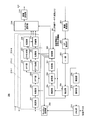
- FIG. 5 is a block diagram showing a configuration of base station 100 according to the present embodiment.
- Base station 100 communicates with a terminal using a unit band group including N downlink unit bands and uplink unit bands.
- control section 101 includes a downlink resource (that is, downlink control information allocation resource) for transmitting control information to resource allocation target terminal 200 and the control information. And assigns (assigns) downlink resources (that is, downlink data allocation resources) for transmitting downlink data.
- This resource allocation is performed in a downlink unit band included in a unit band group configured (configured) in the resource allocation target terminal 200.
- the downlink control information allocation resource is selected in a resource corresponding to a downlink control channel (PDCCH) in each downlink unit band.
- the downlink data allocation resource is selected in a resource corresponding to a downlink data channel (PDSCH) in each downlink unit band.
- the control unit 101 allocates different resources to each of the resource allocation target terminals 200.
- the downlink control information allocation resource is equivalent to the above-mentioned L1 / L2CCH. That is, the downlink control information allocation resource is composed of one or a plurality of CCEs. Further, each CCE included in the downlink control information allocation resource is associated with the configuration resource of the uplink control channel (PUCCH) on a one-to-one basis. However, the association between the CCE and the PUCCH configuration resource is made by associating the downlink unit band and the uplink unit band broadcasted for the LTE system.
- control unit 101 determines a coding rate used when transmitting control information to the resource allocation target terminal 200. Since the data amount of control information differs according to the coding rate, downlink control information allocation resources having a number of CCEs to which control information of this data amount can be mapped are allocated by the control unit 101.
- control part 101 outputs the information regarding a downlink data allocation resource with respect to the control information generation part 102.
- the control unit 101 outputs information on the coding rate used when transmitting control information to the coding unit 103.
- Control section 101 also determines the coding rate of transmission data (that is, downlink data) and outputs the coding rate to coding section 105.
- the control unit 101 outputs information on the downlink data allocation resource and the downlink control information allocation resource to the mapping unit 108.
- the control unit 101 performs control so as to map downlink data and downlink allocation control information for reporting downlink data allocation resources used by the downlink data to the same downlink unit band.
- the control information generation unit 102 generates control information notifying the downlink data allocation resource and outputs the control information to the encoding unit 103. This control information is generated for each downlink unit band. Further, when there are a plurality of resource allocation target terminals 200, the control information includes the terminal ID of the destination terminal in order to distinguish the resource allocation target terminals 200 from each other. For example, CRC bits masked with the terminal ID of the destination terminal are included in the control information. This control information may be referred to as “downlink allocation control information”.
- the encoding unit 103 encodes the control information input from the control information generation unit 102 according to the encoding rate received from the control unit 101, and outputs the encoded control information to the modulation unit 104.
- Modulation section 104 modulates the encoded control information and outputs the obtained modulated signal to mapping section 108.
- Encoding section 105 receives transmission data (that is, downlink data) for each transmission destination terminal 200 and encoding rate information from control section 101, and encodes transmission data at the encoding rate indicated by the encoding rate information. And output to the data transmission control unit 106. However, when a plurality of downlink unit bands are allocated to transmission destination terminal 200, encoding section 105 encodes transmission data transmitted in each downlink unit band, and transmits the encoded transmission data as data. The data is output to the transmission control unit 106.
- the data transmission control unit 106 holds the encoded transmission data and outputs the encoded transmission data to the modulation unit 107 during the initial transmission.
- the encoded transmission data is held for each transmission destination terminal 200. Further, transmission data to one transmission destination terminal 200 is held for each downlink unit band to be transmitted. As a result, not only retransmission control of the entire data transmitted to the transmission destination terminal 200 but also retransmission control for each downlink unit band is possible.
- the data transmission control unit 106 when the retransmission control signal received from the retransmission control signal generation unit 119 indicates a retransmission command, the data transmission control unit 106 outputs retained data corresponding to the retransmission control signal to the modulation unit 107. In addition, when the retransmission control signal received from the retransmission control signal generation unit 119 indicates that the retransmission control signal is not retransmitted, the data transmission control unit 106 deletes the retained data corresponding to the retransmission control signal. In this case, the data transmission control unit 106 outputs the next initial transmission data to the modulation unit 107.
- a bundle ACK / NACK signal related to a plurality of transmission data is transmitted from terminal 200, when receiving a retransmission control signal indicating a retransmission command, data transmission control section 106 receives the bundle ACK / NACK signal. A plurality of related retained data is output to the modulation unit 107.
- Modulation section 107 modulates the encoded transmission data received from data transmission control section 106 and outputs the modulated signal to mapping section 108.
- Mapping section 108 maps the modulation signal (downlink allocation control information) of the control information received from modulation section 104 to the resource (resource in PDCCH) indicated by the downlink control information allocation resource received from control section 101, and passes to IFFT section 109. Output.
- mapping section 108 maps the modulation signal (downlink data) of the transmission data received from modulation section 107 to the resource (resource in PDSCH) indicated by the downlink data allocation resource received from control section 101, and to IFFT section 109. Output.
- Control information and transmission data (downlink data) mapped to a plurality of subcarriers in a plurality of downlink unit bands by mapping section 108 are converted from frequency domain signals to time domain signals by IFFT section 109, and CP adding section 110.
- the wireless transmission unit 111 After the CP is added to the OFDM signal, the wireless transmission unit 111 performs transmission processing such as D / A conversion, amplification, and up-conversion, and transmits the result to the terminal 200 via the antenna.
- downlink allocation control information is transmitted on the downlink control channels of N downlink unit bands, and downlink data is transmitted on the downlink data channel indicated by the downlink allocation control information.
- the radio reception unit 112 receives an uplink control channel signal (PUCCH signal) transmitted from the terminal 200 via an antenna, and performs reception processing such as down-conversion and A / D conversion on the received signal.
- PUCCH signal includes a response signal, SR, or a reference signal.
- the CP removal unit 113 removes the CP added to the reception signal after the reception process.
- the PUCCH extraction unit 114 extracts the uplink control channel signal included in the received signal for each uplink unit band, and distributes the extracted uplink control channel signal for each uplink unit band.
- the uplink control channel signal may include a response signal, SR, and reference signal transmitted from the terminal 200.
- SR response signal
- the unit band group set in terminal 200 there is only one uplink unit band that may contain SR.
- the SR is transmitted only in the uplink unit band used for transmitting the bundle ACK / NACK signal when the terminal has successfully received the downlink allocation control information in all the downlink unit bands.
- the despreading unit 115-N and the correlation processing unit 117-N process the uplink control channel signal extracted in the uplink unit band N.
- Base station 100 is provided with a processing system of despreading section 115 and correlation processing section 117 corresponding to each of upstream unit bands 1 to N that can be used by base station 100.
- despreading section 115 uses an orthogonal code sequence corresponding to a response signal resource (ACK / NACK resource) from terminal 200 and an orthogonal code sequence corresponding to an SR resource allocated to terminal 200. , The signal received via the ACK / NACK resource and the signal received via the SR resource are despread, and the despread signal is output to the correlation processing unit 117.
- Sequence controller 116 generates a ZAC sequence corresponding to an ACK / NACK resource or SR resource transmitted from terminal 200.
- sequence control section 116 identifies a correlation window in which signal components from terminal 200 are included in each of uplink unit bands 1 to N based on the generated ZAC sequence. Then, sequence control unit 116 outputs information indicating the identified correlation window and the generated ZAC sequence to correlation processing unit 117.
- the correlation processing unit 117 uses the information indicating the correlation window and the ZAC sequence input from the sequence control unit 116 to obtain a correlation value between the despread signal and the ZAC sequence, and outputs the correlation value to the determination unit 118.
- the determination unit 118 determines whether a response signal or SR is transmitted from the terminal based on the correlation value input from the correlation processing unit 117 corresponding to each of the uplink unit bands 1 to N. That is, the determination unit 118 compares a plurality of correlation values corresponding to the resources that may be used for transmission of the response signal in each uplink unit band and the SR resources with the threshold value, and determines the response signal or It is determined whether SR is transmitted from the terminal.
- the determination unit 118 determines that a resource that may be used for response signal transmission in each uplink unit band and a plurality of correlation values respectively corresponding to SR resources are less than a threshold value.
- Terminal 200 determines that neither a response signal nor SR is transmitted (DTX).
- determination section 118 outputs information indicating “SR of PUCCH resource and DTX for response signal” to retransmission control signal generation section 119.
- the determination unit 118 has at least one of a plurality of correlation values respectively corresponding to a resource that may be used for transmission of a response signal in each uplink unit band and an SR resource equal to or greater than a threshold value, and When the correlation value corresponding to the SR resource is the largest, it is determined from the terminal 200 that only SR or both the response signal and SR are transmitted using the SR resource.
- the determination unit 118 has at least one of a plurality of correlation values respectively corresponding to a resource that may be used for transmission of a response signal in each uplink unit band and an SR resource equal to or greater than a threshold value, and When the correlation value corresponding to the SR resource is not the maximum, it is determined that only the response signal is transmitted from the terminal 200 using the ACK / NACK resource (that is, it is determined that the SR is not transmitted). When determining that the terminal 200 is transmitting a response signal, the determining unit 118 further determines, for example, by synchronous detection whether the response signal indicates ACK or NACK.
- the determination unit 118 outputs the determination result (ACK or NACK) for each terminal and the information indicating the uplink unit band in which the response signal is detected, or DTX information to the retransmission control signal generation unit 119, and the SR detection status Is output to an uplink resource allocation control unit (not shown).
- the uplink resource allocation control unit (not shown) receives the SR, the base station 100 transmits uplink allocation control information for reporting the uplink data allocation resource so that the terminal 200 can transmit uplink data. Transmit to terminal 200. In this way, base station 100 determines whether it is necessary to allocate resources for uplink data to terminal 200 based on the uplink control channel. Details of operations in the uplink resource allocation control unit and details of resource allocation operations for uplink data for terminal 200 in base station 100 are omitted.
- retransmission control signal generation section 119 should retransmit the data (downlink data) transmitted in each downlink unit band based on the determination result (ACK or NACK) or DTX information related to the response signal input from determination section 118 And a retransmission control signal is generated based on the determination result.
- retransmission control signal generation section 119 when receiving a response signal or DTX indicating NACK, retransmission control signal generation section 119 generates a retransmission control signal indicating a retransmission command and outputs the retransmission control signal to data transmission control section 106.
- retransmission control signal generation section 119 When receiving a response signal indicating ACK, retransmission control signal generation section 119 generates a retransmission control signal indicating that retransmission is not performed, and outputs the retransmission control signal to data transmission control section 106.
- FIG. 6 is a block diagram showing a configuration of terminal 200 according to the present embodiment.
- the terminal 200 communicates with the base station 100 using a unit band group composed of N downlink unit bands and N uplink unit bands, and receives an error detection result of downlink data arranged in the downlink unit band.
- the response signal based on this is transmitted on the uplink control channel of the uplink unit band corresponding to the downlink unit band.
- radio reception section 201 receives an OFDM signal transmitted from base station 100 via an antenna, and performs reception processing such as down-conversion and A / D conversion on the received OFDM signal.
- the received OFDM signal includes a PDSCH signal or a PDCCH signal. That is, terminal 200 receives downlink allocation control information on a downlink control channel of N downlink unit bands, and receives downlink data on a downlink data channel indicated by the downlink allocation control information.
- CP removing section 202 removes the CP added to the OFDM signal after reception processing.
- the FFT unit 203 performs FFT on the received OFDM signal and converts it into a frequency domain signal, and outputs the obtained received signal to the extracting unit 204.
- the extraction unit 204 extracts a downlink control channel signal (PDCCH signal) from the received signal received from the FFT unit 203 according to the input coding rate information. That is, since the number of CCEs constituting the downlink control information allocation resource changes according to the coding rate, the extraction unit 204 extracts the downlink control channel signal using the number of CCEs corresponding to the coding rate as an extraction unit. . Further, the downlink control channel signal is extracted for each downlink unit band. The extracted downlink control channel signal is output to demodulation section 205.
- PDCCH signal downlink control channel signal
- the extraction unit 204 extracts downlink data (downlink data channel signal (PDSCH signal)) from the received signal based on the information on the downlink data allocation resource addressed to the own device received from the determination unit 207, and sends it to the demodulation unit 209. Output.
- PDSCH signal downlink data channel signal
- the demodulation unit 205 demodulates the downlink control channel signal received from the extraction unit 204 and outputs the obtained demodulation result to the decoding unit 206.
- the decoding unit 206 decodes the demodulation result received from the demodulation unit 205 according to the input coding rate information, and outputs the obtained decoding result to the determination unit 207.
- the determination unit 207 identifies and identifies the downlink unit band to which the downlink allocation control information addressed to the own device is mapped, and the CCE to which the downlink allocation control information addressed to the own device is mapped in the downlink unit band.
- the downlink unit band identification information and the CCE identification information are output to the control unit 208.
- the control unit 208 identifies an uplink unit band that is a pair of downlink unit bands indicated by the identification information of the downlink unit band received from the determination unit 207, and a PUCCH resource (frequency / code) corresponding to the CCE indicated by the CCE identification information To do. Then, the control unit 208 converts the ZAC sequence and cyclic shift amount corresponding to the PUCCH resource specified in each uplink unit band that is a pair of each downlink unit band into the uplink control channel signal generation unit 213-corresponding to each uplink unit band. 1 to N spreading sections 222 and output frequency resource information to IFFT section 223.
- control unit 208 outputs the ZAC sequence and frequency resource information as the reference signal to the IFFT unit 226, outputs the orthogonal code sequence to be used for the secondary spreading of the response signal to the spreading unit 225, and outputs the secondary signal of the reference signal.
- An orthogonal code sequence to be used for spreading is output to spreading section 228.
- the control unit 208 when the control unit 208 receives an SR from an uplink data generation unit (not shown), the PUCCH resource (SR resource) to transmit the SR based on the SR resource information notified in advance from the base station 100 Is identified. Then, the control unit 208 outputs the ZAC sequence corresponding to the SR resource and the cyclic shift amount to the spreading unit 222 of the uplink control channel signal generation units 213-1 to 213-1 corresponding to the uplink unit band that should transmit the SR, The frequency resource information is output to IFFT section 223.
- control unit 208 outputs a ZAC sequence and frequency resource information as a reference signal corresponding to the SR resource to the IFFT unit 226, and an orthogonal code sequence to be used for secondary spreading corresponding to the SR resource is transmitted to the spreading unit 225 and the spreading. To the unit 228.
- control section 208 instructs PUCCH selection section 214 as to the uplink unit band that the own apparatus should use for PUCCH transmission.
- the control unit 208 corresponds to the uplink unit band to which the SR is to be transmitted.
- the Bundling control unit 212 is instructed to output NACK to the uplink control channel signal generation unit 213. Details of SR and response signal transmission control in control unit 208 will be described later.
- Demodulation section 209 demodulates the downlink data received from extraction section 204, and outputs the demodulated downlink data to decoding section 210.
- Decoding section 210 decodes the downlink data received from demodulation section 209 and outputs the decoded downlink data to CRC section 211.
- the Bundling control unit 212 transmits the downlink data (or downlink allocation control information) transmitted in each downlink unit band included in the unit band group set in the own device to the base station 100 based on the reception status of the downlink data (or downlink allocation control information). A response signal to be transmitted is generated.
- the Bundling control unit 212 generates a bundle ACK / NACK signal as a response signal based on whether the downlink data is received successfully. More specifically, when the own device receives downlink assignment control information corresponding to all downlink data, the bundling control unit 212 obtains a bundle ACK by obtaining a logical product of response signals for a plurality of downlink data. / NACK signal is generated. Also, when the own device receives only downlink allocation control information corresponding to some downlink data, the Bundling control unit 212 generates a NACK as a bundled ACK / NACK signal. The bundle control unit 212 outputs the bundled ACK / NACK signal to the uplink control channel signal generation unit 213 corresponding to one uplink unit band.
- the Bundling control unit 212 when instructed by the control unit 208, the Bundling control unit 212 outputs NACK to the uplink control channel signal generation unit 213 corresponding to the uplink unit band that should transmit the SR.
- the uplink control channel signal generation unit 213 generates an uplink control channel signal (PUCCH signal) transmitted in the uplink unit band based on the response signal received from the Bundling control unit 212.
- Terminal 200 is provided with uplink control channel signal generators 213-1 to 213-1 corresponding to uplink unit bands 1 to N that can be used by base station 100 and terminal 200, respectively.
- the uplink control channel signal generation unit 213 includes a modulation unit 221, a spreading unit 222, an IFFT unit 223, a CP adding unit 224, a spreading unit 225, an IFFT unit 226, and a CP adding unit 227. , A diffusion unit 228 and a multiplexing unit 229.
- the modulation unit 221 modulates the response signal input from the Bundling control unit 212 and outputs the modulated response signal to the spreading unit 222.
- the spreading unit 222 performs first spreading of the response signal based on the ZAC sequence and the cyclic shift amount set by the control unit 208, and outputs the response signal after the first spreading to the IFFT unit 223. That is, spreading section 222 performs first spreading of the response signal in accordance with an instruction from control section 208.
- the IFFT unit 223 arranges the response signal after the first spreading on the frequency axis based on the frequency resource information input from the control unit 208, and performs IFFT. Then, IFFT section 223 outputs the response signal after IFFT to CP adding section 224.
- the CP adding unit 224 adds the same signal as the tail part of the response signal after IFFT to the head of the response signal as a CP.
- Spreading section 225 uses the orthogonal code sequence set by control section 208 to secondarily spread the response signal after CP addition, and outputs the response signal after the second spreading to multiplexing section 229. That is, spreading section 225 performs second spreading on the response signal after the first spreading using the orthogonal code sequence corresponding to the resource selected by control section 208.
- the IFFT unit 226 arranges the reference signal on the frequency axis based on the frequency resource information input from the control unit 208, and performs IFFT. Then, IFFT unit 226 outputs the reference signal after IFFT to CP adding unit 227.
- the CP adding unit 227 adds the same signal as the tail part of the reference signal after IFFT to the head of the reference signal as a CP.
- Spreading section 228 spreads the reference signal after CP addition with the orthogonal code sequence instructed from control section 208 and outputs the spread reference signal to multiplexing section 229.
- the multiplexing unit 229 time-multiplexes the response signal after second spreading and the reference signal after spreading into one slot, and outputs the result to the PUCCH selection unit 214.
- the PUCCH selection unit 214 specifies the uplink unit band from the uplink unit bands 1 to N to transmit the PUCCH signal according to the instruction from the control unit 208. Then, PUCCH selection section 214 outputs an uplink control channel signal (PUCCH signal) input from multiplexing section 229 of uplink control channel signal generation section 213 corresponding to the specified uplink unit band to radio transmission section 215.
- PUCCH signal uplink control channel signal
- Radio transmission section 215 performs transmission processing such as D / A conversion, amplification and up-conversion on the signal received from PUCCH selection section 214, and transmits the signal to base station 100 from the antenna.
- the terminal 200 is configured with two downlink unit bands, downlink unit bands 1 and 2, and two uplink unit bands, uplink unit bands 1 and 2.
- a symmetric unit band group is set.
- Base station 100 then transmits downlink allocation control information and downlink data in downlink unit bands 1 and 2, respectively.
- the uplink unit shown in FIG. 7A is used as an uplink unit band to be used for transmission of bundle ACK / NACK signals when terminal 200 receives downlink allocation control information in two downlink unit bands 1 and 2 (that is, normal case).
- Band 1 is set.
- base station 100 notifies terminal 200 of one resource (SR resource) for transmitting SR.
- SR resource resource
- the SR resource is set to the same uplink unit band (uplink unit band 1 in FIG. 7A) as the uplink unit band to be used for transmitting the bundled ACK / NACK signal in the Bundling mode.
- the plurality of CCEs constituting PDCCH1 of downlink unit band 1 shown in FIG. 7A are respectively associated with the configuration resources of PUCCH1 of uplink unit band 1, and constitute PDCCH2 of downlink unit band 2 shown in FIG. 7A.
- the plurality of CCEs are associated with the configuration resources of the PUCCH 2 of the uplink unit band 2, respectively.
- terminal 200 it is assumed that SR and a response signal (bundle ACK / NACK signal) for downlink data are generated in the same subframe.
- ⁇ Normal case when terminal 200 receives both downlink assignment control information transmitted in two downlink unit bands> That is, terminal 200, in FIG. 7B (normal case), downlink unit band 2 corresponding to uplink unit band 1 to which SR resource is allocated and uplink unit band 2 that is different from uplink unit band 1 to which SR resource is allocated. Both receive downlink allocation control information.
- Bundling control section 212 is based on each error detection result (“ACK” or “NACK”) for downlink data received from downlink unit bands 1 and 2 input from CRC section 211. , A bundle ACK / NACK signal (logical product of a response signal for downlink data received in downlink unit band 1 and a response signal for downlink data received in downlink unit band 2) is generated.
- control unit 208 specifies the uplink unit bands 1 and 2 that form a pair with the downlink unit bands 1 and 2 to which the downlink allocation control information addressed to the own device is mapped in the unit band group shown in FIG. Further, the PUCCH resource corresponding to the CCE to which the downlink allocation control information is mapped is specified. Further, in FIG. 7A, since the own device has received downlink data in two downlink unit bands 1 and 2, the control unit 208 uses the constituent resources of the specified PUCCH1 and PUCCH2 for transmission of bundled ACK / NACK signals in advance.
- the configured resource of PUCCH1 of uplink unit band 1 (ACK / NACK resource “A / N” of PUCCH1 shown in FIG. 7B (normal case)) is specified as a PUCCH resource to be used for transmission of bundled ACK / NACK signals .
- the uplink unit band to be used for SR transmission and the uplink to be used for bundle ACK / NACK signal transmission is the same (uplink unit band 1).
- control unit 208 controls to transmit a bundle ACK / NACK signal using the SR resource of the uplink unit band 1.
- control section 208 instructs ZAC sequences and orthogonal code sequences corresponding to SR resources to spreading section 222 and spreading section 225 of uplink control channel signal generation section 213 corresponding to uplink unit band 1, respectively. To do.
- terminal 200 transmits the bundle ACK / NACK signal using the SR resource included in PUCCH1 of uplink unit band 1.
- the base station 100 determines that the terminal 200 has transmitted the SR because the SR resource is used in the PUCCH 1 of the uplink unit band 1 shown in FIG. 7B (normal case). Further, base station 100 determines whether terminal 200 has transmitted ACK or NACK as a bundled ACK / NACK signal based on the phase of the signal received by the SR resource (that is, based on the demodulation result by BPSK or QPSK). Determine.
- terminal 200 uses only the SR resource of one uplink unit band (uplink unit band 1 in FIG. 7B (normal case)).
- Bundle ACK / NACK signals can be transmitted.
- Bundling control section 212 receives an error detection result (“ACK” or “NACK”) for downlink data received in downlink unit band 1 input from CRC section 211, and a downlink in downlink unit band 2.
- ACK error detection result
- NACK A logical product with NACK indicating failure in receiving the allocation control information, that is, NACK is generated as a bundle ACK / NACK signal.
- control unit 208 specifies the uplink unit band 1 that forms a pair with the downlink unit band 1 to which the downlink allocation control information addressed to itself is mapped in the unit band group shown in FIG. 7A, and further performs downlink allocation control.
- the PUCCH resource corresponding to the CCE to which the information is mapped is specified. That is, the control unit 208 transmits the configuration resource of PUCCH1 of uplink unit band 1 (ACK / NACK resource “A / N” of PUCCH1 shown in FIG. 7B (error case 1)) to transmit a bundled ACK / NACK signal (NACK). It is specified as a PUCCH resource to be used.
- the uplink unit band to be used for transmitting the SR and the bundled ACK / NACK signal should be used for transmission.
- the uplink unit band is the same (uplink unit band 1).
- control unit 208 performs control so as to transmit a bundled ACK / NACK signal using the SR resource of the uplink unit band 1 as illustrated in FIG. 7B (error case 1).
- control unit 208 performs the same processing as in FIG. 7B (normal case). That is, control section 208 instructs ZAC sequences and orthogonal code sequences corresponding to SR resources to spreading section 222 and spreading section 225 of uplink control channel signal generation section 213 corresponding to uplink unit band 1, respectively.
- terminal 200 transmits the bundle ACK / NACK signal using the SR resource included in PUCCH1 of uplink unit band 1.
- the base station 100 determines that the terminal 200 has transmitted the SR because the SR resource is used in the PUCCH 1 of the uplink unit band 1 shown in FIG. 7B (error case 1). To do. Also, base station 100 determines that terminal 200 has transmitted NACK as a bundled ACK / NACK signal based on the phase of the signal received by the SR resource.
- terminal 200 uses only the SR resource of one uplink unit band (uplink unit band 1 in FIG. 7B (error case 1)). Thus, a bundle ACK / NACK signal can be transmitted.
- terminal 200 is not limited to error case 1 (in the case where reception of downlink allocation control information of downlink unit band 2 fails in FIG. 7B), but base station 100 does not provide SR resources to terminal 200.
- the present invention can also be applied to a case where downlink assignment control information is transmitted only by the downlink unit band (downlink unit band 1 in FIG. 7B) that forms a pair with the assigned uplink unit band. That is, terminal 200 determines the number of downlink allocation control information actually received by itself and the received downlink allocation, regardless of how many downlink unit bands base station 100 has actually transmitted downlink allocation control information.
- a response signal transmission method when the SR and the response signal are generated in the same subframe is determined according to the position of the downlink unit band to which the control information is mapped.
- ⁇ Error case 2 When terminal 200 receives only downlink allocation control information transmitted in downlink unit band 2> That is, in FIG. 7B (error case 2), terminal 200 receives downlink assignment control information only in downlink unit band 2 corresponding to uplink unit band 2 different from uplink unit band 1 to which the SR resource is assigned.
- Bundling control section 212 receives error detection result (“ACK” or “NACK”) for downlink data received in downlink unit band 2 input from CRC section 211, and downlink unit band 1 A logical product with NACK indicating failure in reception of downlink allocation control information at N, that is, NACK is generated as a bundled ACK / NACK signal.
- ACK error detection result
- NACK A logical product with NACK indicating failure in reception of downlink allocation control information at N, that is, NACK is generated as a bundled ACK / NACK signal.
- control unit 208 identifies the uplink unit band 2 that forms a pair with the downlink unit band 2 to which the downlink allocation control information addressed to itself is mapped in the unit band group shown in FIG. 7A, and further performs downlink allocation control.
- the PUCCH resource corresponding to the CCE to which the information is mapped is specified. That is, control section 208 specifies the PUCCH2 configuration resource of uplink unit band 2 as a PUCCH resource to be used for transmission of bundled ACK / NACK signal (NACK).
- the control unit 208 controls to transmit a bundled ACK / NACK signal using the ACK / NACK resource of the uplink unit band 2. That is, as shown in FIG. 7B (error case 2), the control unit 208 does not use the SR resource of the uplink unit band 1. That is, terminal 200 does not transmit SR (drops SR).
- control unit 208 occupies the downlink allocation control information received in the downlink unit band 2 for the spreading unit 222 and the spreading unit 225 of the uplink control channel signal generation unit 213 corresponding to the uplink unit band 2.
- the ZAC sequence and the orthogonal code sequence corresponding to the PUCCH resource associated with the CCE that has been indicated are respectively indicated.
- terminal 200 transmits a bundled ACK / NACK signal using ACK / NACK resource “A / N” included in PUCCH2 of uplink unit band 2.
- terminal 200 does not use the SR resource included in PUCCH1 of uplink unit band 1.
- terminal 200 transmits NACK based on the phase of the signal received by ACK / NACK resource “A / N” included in PUCCH2 of uplink unit band 2 shown in FIG. 7B (error case 2). Determine what happened. Further, since base station 100 uses the ACK / NACK resource included in PUCCH2 of uplink unit band 2 shown in FIG. 7B (error case 2), downlink allocation in which terminal 200 is transmitted in downlink unit band 2 is used. Since it is possible to know that only control information has been successfully received (that is, reception of downlink allocation control information transmitted in downlink unit band 1 has failed), efficient retransmission control can be performed on downlink data. Can be applied.
- terminal 200 uses only the ACK / NACK resource of one uplink unit band (uplink unit band 2 in FIG. 7B (error case 2)). Bundle ACK / NACK signals can be transmitted.
- the SR resource of the uplink unit band 1 is not used even though the SR has occurred, and therefore the base station 100 cannot determine that the SR has occurred on the terminal 200 side.
- the error rate of the downlink allocation control information that is, the TargetCHBlock error rate (Target BLER) of the PDCCH signal
- the tolerance of delay for data for which a transmission request is newly generated in terminal 200 is large. Therefore, when SR and the response signal occur in the same subframe, only in FIG. 7B (error case 2), terminal 200 does not use the SR resource (that is, SR is not transmitted). The impact on the entire system is extremely small.
- terminal 200 The operation of terminal 200 described above is not limited to error case 2 (in the case where reception of downlink allocation control information of downlink unit band 1 fails in FIG. 7B), but base station 100 performs downlink unit band 2 to terminal 200.
- the present invention can also be applied when transmitting downlink allocation control information only.
- the base station 100 allocates downlink data (that is, downlink allocation control information) only to the downlink unit band 2.
- downlink allocation control information that is, downlink allocation control information
- SR and response signal are similar to FIG. 7B (error case 2). Will occur in different upstream unit bands.
- the base station 100 sets a pair with an uplink unit band different from the uplink unit band to which the SR is to be transmitted, to the terminal 200.
- the operation of assigning downlink data only to the configured downlink unit band is not performed.
- ⁇ Error case 3 When terminal 200 has not received any downlink allocation control information transmitted in downlink unit bands 1 and 2>
- terminal 200 does not know the presence of downlink allocation control information transmitted by base station 100 in downlink unit bands 1 and 2, and cannot receive downlink data, so there is a response signal to be transmitted. do not do. Therefore, as shown in FIG. 7B (error case 3), terminal 200 transmits the SR using the SR resource.
- terminal 200 when transmitting only SR (when there is no response signal), transmits SR using the same phase point as NACK (that is, constellation point). In other words, terminal 200 transmits NACK using SR resources.
- control unit 208 outputs a NACK to the uplink control channel signal generation unit 213 corresponding to the uplink unit band 1 (uplink unit band in which the SR resource is set) to the Bundling control unit 212. Instruct.
- control section 208 instructs ZAC sequence and orthogonal code sequence corresponding to SR to spreading section 222 and spreading section 225 of uplink control channel signal generation section 213 corresponding to uplink unit band 1, respectively.
- terminal 200 transmits only SR (signal having the same phase point as NACK) using the SR resource included in PUCCH1 of uplink unit band 1. .
- the base station 100 determines this SR as SR and NACK. Therefore, the base station 100 performs not only resource allocation processing for uplink data but also retransmission processing of downlink data.
- FIG. 7B error case 3
- base station 100 is Failure to receive downlink allocation control information can be specified.
- terminal 200 is not limited to error case 3 (in the case where reception of both downlink allocation control information of downlink unit bands 1 and 2 fails in FIG. 7B), but base station 100 does not respond to terminal 200.
- the present invention can also be applied to a case where downlink allocation control information is not transmitted in any downlink unit band (that is, when downlink data is not allocated to terminal 200).
- the base station 100 receives an SR transmitted at the same phase point as that of NACK, the base station 100 determines that the terminal 200 has transmitted the SR alone.
- the base station 100 determines that the received SR is SR + NACK (that is, uplink) depending on whether or not the own station has assigned downlink data to the terminal 200 (whether or not downlink assignment control information has been transmitted). It is determined whether it is a data allocation request + retransmission request) or only SR (that is, only uplink data allocation request).
- the terminal has failed to receive downlink assignment control information, or the base station has not assigned downlink data. Regardless of this, the base station can perform optimal retransmission control according to the allocation status of the base station.
- the uplink unit band provided with the PUCCH resource including the SR resource (that is, the uplink unit band used for transmitting the SR) and the PUCCH resource associated with the CCE occupied by the downlink allocation control information are
- terminal 200 determines that the PUCCH resource associated with the CCE occupied by the downlink assignment control information
- the bundle ACK / NACK signal is transmitted using, while the SR is not transmitted.
- terminal 200 transmits a response signal (bundle ACK / NACK signal) for downlink data transmitted on the downlink data channel indicated by the downlink allocation control information to another uplink unit band (uplink unit band 2 in FIG. 7A).
- ACK / NACK resource “A / N” included in the uplink control channel (PUCCH2 in FIG. 7A) and SR is not transmitted.
- a specific uplink unit band to which the SR resource is assigned (uplink unit band 1 in FIG. 7A) among the unit band groups set in the own device.
- downlink allocation control information is received in both unit bands 2) (that is, FIG.
- the terminal 200 when the SR and the response signal (bundled ACK / NACK signal) are generated in the same subframe (within the same transmission unit time), the terminal 200 and the uplink unit band to be transmitted with the bundle ACK Depending on whether or not the uplink unit band to which the / NACK signal should be transmitted is the same, it is determined whether to transmit the response signal using the SR resource or to transmit only the response signal preferentially.
- the terminal 200 even when the SR and the response signal occur in the same subframe, the terminal 200 always has one uplink unit band (normal case and normal case).
- the response signal is transmitted using only the uplink unit band 1 in error case 1 and the uplink unit band 2) in error case 2. That is, terminal 200 can suppress the band used in the uplink to only the minimum uplink unit band necessary for transmission of the response signal. Thereby, terminal 200 can suppress power consumption during transmission of the response signal.
- the SR and the response signal are signals having the same format, when the SR and the response signal are transmitted in the same subframe, the single carrier characteristics ( Or, CM (Cubic-Metric) characteristics) deteriorate.
- CM Cubic-Metric
- terminal 200 uses only one of the SR resource and the ACK / NACK resource. One signal is transmitted. Therefore, even when SR and a response signal are generated in the same subframe, terminal 200 can simultaneously notify the SR and the response signal in normal case and error case 1 while maintaining single carrier characteristics. .
- the probability of occurrence of error case 2 shown in FIG. 7B (PDCCH signal Target BLER) is about 1% as described above. Therefore, terminal 200 can minimize the frequency at which the SR resource is not used (that is, the frequency at which the SR is not transmitted) when the SR and the response signal are generated in the same subframe. Also, the delay tolerance for data for which a transmission request is newly generated in terminal 200 is large. For this reason, even if SR occurs, even if terminal 200 gives priority to transmission of a response signal and does not transmit SR, the influence on the entire system is extremely small.
- the power consumption of the terminal can be suppressed while maintaining the single carrier characteristics.
- the terminal when the SR and the response signal occur in different uplink unit bands in the same subframe (that is, in error case 2), the terminal does not transmit the SR (that is, drops the SR) Case).
- the terminal when the SR and the response signal occur in different uplink unit bands in the same subframe (that is, in error case 2), the terminal may not transmit the response signal.
- the terminal transmits only SR at the NACK phase point.
- the base station side indicates that the terminal has successfully received only the downlink allocation control information transmitted in the downlink unit band 2 (that is, has failed to receive the downlink allocation control information transmitted in the downlink unit band 1). I can not know at. However, SR transmission delay can be reduced instead.
- the base station retransmits all downlink data, so that only the SR is notified at the NACK phase point in this way. Even in this case, the retransmission efficiency does not decrease greatly.
- the operation in error case 2 of the terminal at this time will be described separately for the case where the SR and the response signal for downlink data are generated in the same subframe and the case where the response signal is not generated in the same subframe as follows. That is, when only a response signal is generated on the terminal side, a bundle ACK / NACK signal is generated using A / N (ACK / NACK resource in PUCCH2) of uplink unit band 2 shown in FIG. 7B (error case 2). Send. On the other hand, when the SR and the response signal are generated in the same subframe on the terminal side, a bundle ACK / NACK signal is transmitted using the SR resource in PUCCH1 in uplink unit band 1.
- Embodiment 2 In Embodiment 1, a case has been described in which SR resources are assigned to only one uplink unit band for each terminal, whereas in this embodiment, SR resources are assigned to a plurality of uplink unit bands for each terminal. The case of being assigned to will be described.
- base station 100 when a terminal performs communication using Carrier-aggregation, base station 100 assigns a resource (SR resource) for transmitting SR to all terminals 200 as an uplink unit band. Notify one at a time.
- SR resource a resource for transmitting SR to all terminals 200 as an uplink unit band.
- terminal 200 As shown in FIG. 8A, for terminal 200, as in Embodiment 1, two downlink unit bands of downlink unit bands 1 and 2 and two of uplink unit bands 1 and 2 are used. A symmetric unit band group composed of uplink unit bands is set. Base station 100 then transmits downlink allocation control information and downlink data in downlink unit bands 1 and 2, respectively. Further, as an uplink unit band to be used for transmission of bundle ACK / NACK signals when terminal 200 receives downlink assignment control information in two downlink unit bands 1 and 2 (that is, normal case), the uplink unit shown in FIG. 8A Band 1 is set.
- base station 100 notifies terminal 200 one SR resource for uplink unit bands 1 and 2 (that is, two for terminal 200).
- the plurality of CCEs constituting PDCCH1 of downlink unit band 1 shown in FIG. 8A are respectively associated with the configuration resources of PUCCH1 of uplink unit band 1, and constitute PDCCH2 of downlink unit band 2 shown in FIG. 8A.
- the plurality of CCEs are respectively associated with the configuration resources of the PUCCH 2 of the uplink unit band 2.
- terminal 200 it is assumed that SR and a response signal (bundle ACK / NACK signal) for downlink data are generated in the same subframe.
- Bundling control section 212 performs bundle ACK / NACK based on each error detection result for downlink data received in downlink unit bands 1 and 2 input from CRC section 211. Generate a signal.
- the control unit 208 configures the PUCCH1 configuration resource for the uplink unit band 1 that is preset for transmission of the bundled ACK / NACK signal among the configuration resources of the PUCCH1 and PUCCH2 (FIG. 8B (normal case).
- PUCCH1 ACK / NACK resource “A / N”) shown in FIG. 2) is specified as a PUCCH resource to be used for transmission of bundled ACK / NACK signals.
- control unit 208 provides PUCCH resources specified for transmission of bundled ACK / NACK signals among uplink unit bands 1 and 2 to which SR resources are respectively allocated. Control is performed so as to transmit a bundled ACK / NACK signal using the SR resource of the uplink unit band 1 that has been provided. Specifically, control section 208 instructs ZAC sequence and orthogonal code sequence corresponding to SR resources to spreading section 222 and spreading section 225 of uplink control channel signal generation section 213 corresponding to uplink unit band 1, respectively. To do.
- terminal 200 transmits the bundle ACK / NACK signal using the SR resource included in PUCCH1 of uplink unit band 1.
- the SR resource included in PUCCH2 of uplink unit band 2 shown in FIG. 8B is not used.
- base station 100 determines that terminal 200 has transmitted an SR and a bundled ACK / NACK signal (ACK or NACK) in the SR resource included in PUCCH1 of uplink unit band 1 shown in FIG. 8B (normal case). .
- terminal 200 has one uplink unit band (uplink unit band 1 in FIG. 8B (normal case)).
- a bundle ACK / NACK signal can be transmitted using only SR resources.
- Bundling control section 212 When terminal 200 receives only downlink assignment control information transmitted in downlink unit band 1> In terminal 200, Bundling control section 212 generates a NACK as a bundled ACK / NACK signal, as in the first embodiment.
- control section 208 uses PUCCH1 configuration resources for uplink unit band 1 (ACK / NACK resource “A / N” for PUCCH1 shown in FIG. 8B (error case 1)) as bundle ACK / It is specified as a PUCCH resource to be used for transmission of a NACK signal (NACK).
- PUCCH1 configuration resources for uplink unit band 1 ACK / NACK resource “A / N” for PUCCH1 shown in FIG. 8B (error case 1)
- bundle ACK / It is specified as a PUCCH resource to be used for transmission of a NACK signal (NACK).
- control unit 208 similarly to FIG. 8B (normal case), the control unit 208, as shown in FIG. 8B (error case 1), out of the uplink unit bands 1 and 2 to which the SR resources are respectively allocated, Control is performed to transmit a bundled ACK / NACK signal using the SR resource of uplink unit band 1 provided with the PUCCH resource specified for transmission of the NACK signal. Specifically, the control unit 208 performs the same processing as in FIG. 8B (normal case). That is, control section 208 instructs ZAC sequences and orthogonal code sequences corresponding to SR resources to spreading section 222 and spreading section 225 of uplink control channel signal generation section 213 corresponding to uplink unit band 1, respectively.
- terminal 200 transmits the bundle ACK / NACK signal using the SR resource included in PUCCH1 of uplink unit band 1.
- base station 100 confirms that terminal 200 has transmitted SR and NACK in the SR resource included in PUCCH1 of uplink unit band 1 shown in FIG. 8B (error case 1). Determine.
- terminal 200 uses one uplink unit band (uplink unit band 1 in FIG. 8B (error case 1)).
- uplink unit band 1 in FIG. 8B error case 1
- the bundle ACK / NACK signal can be transmitted using only the SR resource.
- terminal 200 is not limited to error case 1 (in the case where reception of downlink allocation control information of downlink unit band 2 fails in FIG. 8B), but base station 100 does not provide SR resources to terminal 200.
- the present invention can also be applied to a case where downlink assignment control information is transmitted only by the downlink unit band (downlink unit band 1 in FIG. 8B) that forms a pair with the assigned uplink unit band. That is, terminal 200 determines the number of downlink allocation control information actually received by itself and the received downlink allocation, regardless of how many downlink unit bands base station 100 has actually transmitted downlink allocation control information.
- a response signal transmission method when the SR and the response signal are generated in the same subframe is determined according to the position of the downlink unit band to which the control information is mapped.
- ⁇ Error case 2 When terminal 200 receives only downlink allocation control information transmitted in downlink unit band 2> In terminal 200, Bundling control section 212 generates a NACK as a bundled ACK / NACK signal, as in the first embodiment.
- control section 208 uses PUCCH2 configuration resources in uplink unit band 2 (PUCCH2 ACK / NACK resource “A / N” shown in FIG. 8B (error case 2)) as bundle ACK / It is specified as a PUCCH resource to be used for transmission of a NACK signal (NACK).
- PUCCH2 configuration resources in uplink unit band 2 PUCCH2 ACK / NACK resource “A / N” shown in FIG. 8B (error case 2)
- bundle ACK / It is specified as a PUCCH resource to be used for transmission of a NACK signal (NACK).
- control unit 208 determines that the PUCCH resource specified for transmission of the bundled ACK / NACK signal among the uplink unit bands 1 and 2 to which the SR resources are respectively allocated. Control is performed to transmit a bundled ACK / NACK signal using the provided SR resource of uplink unit band 2. Specifically, control section 208 instructs ZAC sequences and orthogonal code sequences corresponding to SR resources to spreading section 222 and spreading section 225 of uplink control channel signal generation section 213 corresponding to uplink unit band 2, respectively. To do.
- terminal 200 transmits the bundle ACK / NACK signal using the SR resource included in PUCCH2 of uplink unit band 2.
- the base station 100 determines that the terminal 200 has transmitted SR and NACK in the SR resource included in the PUCCH 2 of the uplink unit band 2 illustrated in FIG. 8B (error case 1).
- terminal 200 uses only the SR resource of one uplink unit band (uplink unit band 2 in FIG. 8B (error case 2)), and bundles it.
- An ACK / NACK signal can be transmitted.
- terminal 200 The operation of terminal 200 described above is not limited to error case 2 (in the case where reception of downlink allocation control information of downlink unit band 1 fails in FIG. 8B), but base station 100 performs downlink unit band 2 to terminal 200.
- the present invention can also be applied when transmitting downlink allocation control information only. For example, this is a case where the base station 100 allocates downlink data (that is, downlink allocation control information) only to the downlink unit band 2.
- ⁇ Error case 3 When terminal 200 has not received any downlink allocation control information transmitted in downlink unit bands 1 and 2>
- FIG. 8B error case 3
- terminal 200 since terminal 200 does not know the presence of downlink allocation control information transmitted by base station 100 in downlink unit bands 1 and 2 and cannot receive downlink data, as in Embodiment 1, There is no response signal to be transmitted. Therefore, as shown in FIG. 8B (error case 3), terminal 200 transmits the SR using the SR resource.
- the uplink unit band to be used in preference to the SR transmission is It may be set in advance between the base station 100 and the terminal 200, or the terminal 200 may arbitrarily set.
- base station 100 instructs terminal 200 to use the SR resource (that is, the SR resource included in PUCCH1) used in FIG. 8B (normal case) when terminal 200 transmits only SR. do.
- terminal 200 transmits SR using the same phase point as NACK.
- control unit 208 NACKs the uplink control channel signal generation unit 213 corresponding to any uplink unit band (uplink unit band 1 in FIG. 8B (error case 3)) to the Bundling control unit 212. Is output. Also, the control unit 208 instructs the spreading unit 222 and the spreading unit 225 of the uplink control channel signal generation unit 213 corresponding to the uplink unit band 1 respectively to the ZAC sequence and the orthogonal code sequence corresponding to the SR resource.
- the terminal 200 transmits only the SR using the SR resource included in the PUCCH1 of the uplink unit band 1.
- the base station 100 determines this SR as SR and NACK. Therefore, the base station 100 performs not only resource allocation processing for uplink data but also retransmission processing of downlink data.
- terminal 200 is not limited to error case 3 (in the case where reception of both downlink allocation control information of downlink unit bands 1 and 2 fails in FIG. 8B), but base station 100 does not respond to terminal 200.
- the present invention can also be applied to the case where no downlink allocation control information is transmitted in any downlink unit band (that is, when the base station 100 does not allocate downlink data to the terminal 200).
- the base station 100 receives an SR transmitted at the same phase point as that of NACK, the base station 100 determines that the terminal 200 has transmitted the SR alone.
- the terminal 200 allocates SR resources for each uplink unit band of the unit band group set in the own device.
- the terminal 200 uses any SR resource as shown in FIG. 8B (normal case, error cases 1 to 3), Both SR and bundled ACK / NACK signals can be transmitted. Therefore, in terminal 200, when only the uplink control channel signal is transmitted, it is only necessary to always use one uplink unit band, so that it is possible to suppress power consumption during transmission of the response signal.
- terminal 200 always transmits one signal using SR resources even when SR and a response signal occur in the same subframe. To do. Therefore, even when SR and a response signal are generated in the same subframe, terminal 200 can simultaneously notify both SR and the response signal while maintaining single carrier characteristics.
- the power consumption of the terminal can be suppressed while maintaining the single carrier characteristics.
- an SR resource is allocated for each uplink unit band set in the terminal. Therefore, since the terminal transmits only one signal including both the SR and the response signal in the same subframe, the single carrier characteristic of the transmission waveform in the transmission of the transmission signal from the terminal without causing the SR delay. Can be maintained.
- a symmetrical carrier aggregation unique to the terminal 400 is configured in advance between the base station 300 and the terminal 400, which will be described later, and information on the downlink unit band and the uplink unit band to be used by the terminal 400 is as follows. It is shared with the terminal 400.
- base station 300 when terminal 400 performs communication by carrier aggregation, base station 300 assigns a resource (SR resource) for transmitting SR to terminal 400 for each uplink unit band set in terminal 400. One by one.
- SR resource a resource for transmitting SR to terminal 400 for each uplink unit band set in terminal 400.
- FIG. 9 is a block diagram showing a configuration of base station 300 according to the present embodiment.
- the same components as those of the first embodiment (FIG. 5) are denoted by the same reference numerals, and description thereof is omitted.
- determination section 301 uses a response signal or SR in each uplink unit band based on correlation values input from correlation processing section 117 corresponding to each of uplink unit bands 1 to N. Is transmitted from the terminal.
- the determination unit 301 determines that a resource that may be used for response signal transmission in each uplink unit band and a plurality of correlation values respectively corresponding to SR resources are less than a threshold value.
- the terminal 400 determines that neither SR nor a response signal is transmitted (DTX).
- determination section 301 outputs information indicating “SR of PUCCH resource and DTX for response signal” to retransmission control signal generation section 302.
- the determination unit 301 has at least one of a plurality of correlation values respectively corresponding to resources that may be used for response signal transmission in each uplink unit band and SR resources, and the threshold value is greater than or equal to a threshold value, and When the correlation value corresponding to the SR resource is the largest, the terminal 400 tentatively determines that only the SR or both the SR and the response signal are transmitted using the SR resource.
- the determination unit 301 has at least one of a plurality of correlation values respectively corresponding to resources that may be used for response signal transmission in each uplink unit band and SR resources, and the threshold value is greater than or equal to a threshold value, and If the correlation value corresponding to the SR resource is not the maximum, it is provisionally determined that only the response signal is transmitted from terminal 400 using the ACK / NACK resource (that is, it is provisionally determined that SR is not transmitted). ).
- the determination part 301 determines whether SR is transmitted from the terminal 400 based on the temporary determination result in each uplink unit band set to the terminal 400. For example, the number of uplink unit bands tentatively determined that SR is transmitted is the number of uplink unit bands tentatively determined that only the response signal is transmitted (that is, provisional determination that SR is not transmitted). If the number is greater than the number of uplink unit bands, the determination unit 301 determines that the SR has been transmitted from the terminal 400.
- the determination unit 301 determines that the terminal 400 is transmitting a response signal
- the determination unit 301 further determines, for example, by synchronous detection whether the response signal for each uplink unit band indicates ACK or NACK. To do. Then, determination section 301 outputs a determination result (ACK or NACK) for each uplink unit band or DTX information to retransmission control signal generation section 302 for each terminal, and information indicating the SR detection status is allocated to uplink resource allocation. Output to a control unit (not shown).
- Retransmission control signal generation section 302 transmits in each downlink unit band based on determination result (ACK or NACK) or information indicating DTX regarding the response signal for each uplink unit band for each terminal, which is input from determination section 301 It is determined whether or not data (downlink data) should be retransmitted, and a retransmission control signal is generated based on the determination result. Specifically, when receiving a response signal or DTX indicating NACK, retransmission control signal generation section 302 generates a retransmission control signal indicating a retransmission command in a downlink unit band corresponding to the uplink unit band, A retransmission control signal is output to data transmission control section 106.
- the retransmission control signal generation unit 302 when receiving a response signal indicating ACK from a certain uplink unit band, the retransmission control signal generation unit 302 generates a retransmission control signal indicating that data is not retransmitted in the downlink unit band corresponding to the uplink unit band.
- the retransmission control signal is output to the data transmission control unit 106.
- FIG. 10 is a block diagram showing a configuration of terminal 400 according to the present embodiment.
- the same components as those in the first embodiment (FIG. 6) are denoted by the same reference numerals, and description thereof is omitted.
- the control unit 401 identifies an uplink unit band that is a pair of downlink unit bands indicated by the identification information of the downlink unit band received from the determination unit 207, and a PUCCH resource (frequency / code) corresponding to the CCE indicated by the CCE identification information To do. Then, the control unit 401 converts the ZAC sequence and cyclic shift amount corresponding to the PUCCH resource specified in each uplink unit band that is a pair of each downlink unit band into the uplink control channel signal generation unit 213-corresponding to each uplink unit band. 1 to N spreading sections 222 and output frequency resource information to IFFT section 223.
- control unit 401 outputs the ZAC sequence and frequency resource information as the reference signal to the IFFT unit 226, outputs the orthogonal code sequence to be used for the secondary spreading of the response signal to the spreading unit 225, and outputs the secondary signal of the reference signal.
- An orthogonal code sequence to be used for spreading is output to spreading section 228.
- control unit 401 when the control unit 401 receives an SR from an uplink data generation unit (not shown), based on the SR resource information notified in advance from the base station 100, the PUCCH resource (SR resource) that should transmit the SR Is identified. Then, the control unit 401 converts the ZAC sequence and cyclic shift amount corresponding to the SR resource in each uplink unit band into the spreading unit of the uplink control channel signal generation units 213-1 to 213-1 corresponding to the uplink unit band to which the SR is to be transmitted. The frequency resource information is output to the IFFT unit 223.
- control unit 401 outputs the ZAC sequence and frequency resource information as a reference signal to the IFFT unit 226, and outputs the orthogonal code sequence to be used for the second spreading corresponding to the SR resource to the spreading unit 225 and the spreading unit 228. . Also, the control unit 401 instructs the PUCCH multiplexing unit 403 of a plurality of uplink unit bands that the own device should use for transmission of the uplink control channel signal (PUCCH signal). In addition, when there is no response signal to be transmitted in the subframe that has received the SR (that is, when no downlink allocation control information is detected), the control unit 401 corresponds to the uplink unit band to which the SR is to be transmitted. The retransmission control signal control unit 402 is instructed to output NACK to the uplink control channel signal generation unit 213. Details of SR and response signal transmission control in control unit 401 will be described later.
- Retransmission control signal control section 402 is a response signal to be transmitted from base station 300 to base station 300 based on the reception status of downlink data transmitted in each downlink unit band included in the unit band group set in the base station. (That is, a retransmission control signal) is generated. Specifically, retransmission control signal control section 402 generates a response signal for the downlink data of each downlink unit band based on whether or not the downlink data is received in each downlink unit band. Then, retransmission control signal control section 402 outputs a response signal for the downlink data of each downlink unit band to uplink control channel signal generation section 213 corresponding to each uplink unit band paired with each downlink unit band.
- PUCCH multiplexing section 403 is an uplink control channel input from multiplexing section 229 of uplink control channel signal generation section 213 corresponding to a plurality of uplink unit bands specified according to an instruction from control section 401 among uplink unit bands 1 to N.
- the signal (PUCCH signal) is multiplexed on the frequency axis, and the obtained multiplexed signal is output to radio transmission section 215.
- the terminal 400 includes two downlink unit bands 1 and 2 and two uplink unit bands 1 and 2 for the downlink unit bands 1 and 2.
- a symmetric unit band group is set.
- Base station 300 then transmits downlink allocation control information and downlink data in downlink unit bands 1 and 2, respectively.
- a plurality of CCEs constituting PDCCH1 of downlink unit band 1 shown in FIG. 11 are respectively associated with PUCCH configuration resources of uplink unit band 1, and a plurality of CCEs constituting PDCCH2 of downlink unit band 2 shown in FIG. Are associated with PUCCH configuration resources of uplink unit band 2, respectively.
- terminal 200 individually transmits response signals for downlink data received in downlink unit bands 1 and 2, respectively (ie, applying non-bundling mode). Also, base station 300 notifies terminal 400 of one resource (SR resource) for transmitting SR to uplink unit bands 1 and 2 (that is, two to terminal 200). .
- SR resource one resource for transmitting SR to uplink unit bands 1 and 2
- terminal 400 it is assumed that SR and a response signal for downlink data are generated in the same subframe.
- retransmission control signal control section 402 when terminal 400 receives both downlink assignment control information transmitted in two downlink unit bands>
- retransmission control signal control section 402 generates two response signals for the downlink data of each downlink unit band based on the success or failure of the downlink data received in downlink unit bands 1 and 2.
- control unit 401 sets each SR resource of uplink unit bands 1 and 2 (that is, an uplink unit band to be used for transmission of a response signal for each downlink data) paired with each downlink unit band that has received downlink data. Is used to control to transmit a response signal for each downlink data.
- control unit 401 sends a ZAC corresponding to the SR resource of each uplink unit band to the spreading unit 222 and the spreading unit 225 of the uplink control channel signal generation unit 213 corresponding to the uplink unit bands 1 and 2, respectively.
- a sequence and an orthogonal code sequence are indicated respectively.
- control unit 401 instructs the PUCCH multiplexing unit 403 to multiplex uplink control channel signals of the uplink unit bands 1 and 2 on the frequency axis.
- terminal 400 transmits a response signal for downlink data received in downlink unit band 1 using the SR resource included in PUCCH 1 of uplink unit band 1,
- a response signal for the downlink data received in band 2 is transmitted using the SR resource included in PUCCH 2 in uplink unit band 2.
- the base station 300 first uses the SR or SR in the SR resource included in the PUCCH1 of the uplink unit band 1 and the SR resource included in the PUCCH2 of the uplink unit band 2 illustrated in FIG. 11B (normal case). It is temporarily determined that a response signal is being transmitted. Then, base station 300 determines that terminal 400 has transmitted SR according to the provisional determination results of uplink unit bands 1 and 2. Specifically, since the number of uplink unit bands that are provisionally determined to be SR transmitted is two and the number of uplink unit bands that are provisionally determined to be SR is not transmitted is 0, The base station determines that terminal 400 has transmitted the SR. Also, base station 300 determines whether each response signal is an ACK or a NACK by using the SRs received in uplink unit bands 1 and 2, respectively.
- terminal 400 only transmits the SR resource of the uplink unit band (uplink unit bands 1 and 2 in FIG. 11B (normal case)) to which the response signal should be transmitted. It is possible to transmit a response signal using. That is, terminal 400 can simultaneously transmit the SR and the response signal using only the minimum uplink unit band necessary for transmitting the response signal.
- the uplink unit band uplink unit bands 1 and 2 in FIG. 11B (normal case)
- the base station 300 determines whether or not the terminal 400 has transmitted the SR based on the determination results (provisional determination results) of the plurality of SR resources used for transmitting the response signal. Can be further improved.
- retransmission control signal control section 402 When terminal 400 receives only downlink assignment control information transmitted in downlink unit band 1> In terminal 400, retransmission control signal control section 402 generates a response signal for the downlink data received in downlink unit band 1 based on the success or failure of the downlink data received in downlink unit band 1.
- control section 401 uses PUCCH1 configuration resource of uplink unit band 1 (ACK / NACK resource “A / N” of PUCCH1 shown in FIG. 11B (error case 1)) to downlink unit band.
- 1 is specified as a PUCCH resource to be used for transmission of a response signal to the downlink data received in 1.
- control unit 401 transmits the response signal using the SR resource of the uplink unit band 1 provided with the PUCCH resource specified for transmission of the response signal.
- control section 401 instructs ZAC sequences and orthogonal code sequences corresponding to SR resources to spreading section 222 and spreading section 225 of uplink control channel signal generation section 213 corresponding to uplink unit band 1, respectively. To do.
- the terminal 400 transmits the response signal using the SR resource included in the PUCCH1 of the uplink unit band 1.
- terminal 400 transmits the SR and the response signal in the SR resource included in PUCCH1 of uplink unit band 1 shown in FIG. 11B (error case 1). Determine what happened.
- terminal 400 uses the minimum uplink unit band necessary for transmission of the response signal (uplink unit band 1 in FIG. 11B (error case 1)).
- the response signal can be transmitted using only the SR resource.
- terminal 400 The operation of terminal 400 described above is not limited to error case 1 (in the case where reception of downlink allocation control information of downlink unit band 2 fails in FIG. 11B), but base station 300 provides SR resource to terminal 400.
- the present invention can also be applied to a case where downlink assignment control information is transmitted only by a downlink unit band (downlink unit band 1 in FIG. 11B) that forms a pair with the assigned uplink unit band. That is, terminal 400 can determine the number of downlink allocation control information actually received by itself and the received downlink allocation, regardless of how many downlink unit bands base station 300 has actually transmitted downlink allocation control information.
- a response signal transmission method when the SR and the response signal are generated in the same subframe is determined according to the position of the downlink unit band to which the control information is mapped.
- ⁇ Error case 2 When terminal 400 receives only downlink assignment control information transmitted in downlink unit band 2> In terminal 400, retransmission control signal control section 402 receives the downlink received in downlink unit band 2 based on the success or failure of the downlink data received in downlink unit band 2 as in FIG. 11B (error case 1). Generate a response signal for the data.
- control unit 401 receives downlink configuration data of PUCCH2 of uplink unit band 2 (ACK / NACK resource “A / N” of PUCCH2 shown in FIG. 11B (error case 2)) in downlink unit band 2 Is specified as a PUCCH resource to be used for transmission of a response signal.
- control unit 401 uses the uplink unit band 2 provided with the PUCCH resource specified for transmission of the response signal. Control to transmit the response signal using the SR resource. Specifically, control section 401 instructs ZAC sequences and orthogonal code sequences corresponding to SR resources to spreading section 222 and spreading section 225 of uplink control channel signal generation section 213 corresponding to uplink unit band 2, respectively. To do.
- the terminal 400 transmits the response signal using the SR resource included in the PUCCH 2 of the uplink unit band 2.
- the base station 300 determines that the terminal 400 has transmitted the SR and the response signal in the SR resource included in the PUCCH2 of the uplink unit band 2 illustrated in FIG. 11B (error case 2).
- terminal 400 transmits the minimum uplink unit band (FIG. 11B ( In error case 2), it is possible to transmit a response signal using only the SR resource of uplink unit band 2).
- terminal 400 is not limited to error case 2 (in the case where reception of downlink allocation control information of downlink unit band 1 fails in FIG. 11B), but base station 300 transmits downlink unit band 2 to terminal 400.
- the present invention can also be applied when transmitting downlink allocation control information only. For example, this is a case where the base station 300 allocates downlink data (that is, downlink allocation control information) only to the downlink unit band 2.
- ⁇ Error case 3 When terminal 400 has not received any of the downlink assignment control information transmitted in downlink unit bands 1 and 2>
- FIG. 11B error case 3
- terminal 400 since terminal 400 does not know the presence of downlink allocation control information transmitted by base station 300 in downlink unit bands 1 and 2 and cannot receive downlink data, as in Embodiment 1, There is no response signal to be transmitted. Therefore, as shown in FIG. 11B (error case 3), terminal 400 transmits an SR using any one SR resource among a plurality of SR resources.
- the uplink unit band to be used with priority over the transmission of SR is It may be set in advance between the base station 300 and the terminal 400, or the terminal 400 may arbitrarily set.
- terminal 400 transmits SR using the same phase point as NACK.
- control unit 401 transmits, to the retransmission control signal control unit 402, an uplink control channel signal corresponding to an uplink unit band to be used for SR transmission (uplink unit band 1 in FIG. 11B (error case 3)). Instructs the generation unit 213 to output NACK. Also, the control unit 401 instructs the ZAC sequence and the orthogonal code sequence corresponding to the SR resource to the spreading unit 222 and the spreading unit 225 of the uplink control channel signal generation unit 213 corresponding to the uplink unit band 1, respectively.
- terminal 400 transmits only SR (signal having the same phase point as NACK) using the SR resource included in PUCCH1 of uplink unit band 1. .
- the base station 300 determines this SR as SR and NACK. Therefore, base station 300 performs not only resource allocation processing for uplink data but also retransmission processing of downlink data.
- terminal 400 is not limited to error case 3 (in the case where reception of both downlink allocation control information of downlink unit bands 1 and 2 fails in FIG. 11B), but base station 300 does not respond to terminal 400.
- the present invention can also be applied to cases where no downlink allocation control information is transmitted in any downlink unit band (that is, when the base station 300 has not assigned downlink data to the terminal 400).
- the base station 300 receives an SR transmitted at the same phase point as that of NACK, the base station 300 determines that the terminal 400 has transmitted the SR alone.
- the terminal when transmitting only the uplink control channel signal (SR or response signal), the terminal transmits the uplink unit band number (transmission bandwidth) necessary for transmission of the response signal and SR and response signal transmission.
- the required number of upstream unit bands (transmission bandwidth) can be made the same.
- the terminal suppresses the number of uplink unit bands (transmission bandwidth) necessary for transmission of the uplink control channel signal (SR or response signal) to the minimum number of uplink unit bands necessary for transmission of the response signal. Can do. Therefore, power consumption of the terminal can be suppressed.
- terminal 400 uses only one of the SR resources and the ACK / NACK resources in each uplink unit band. One signal is transmitted. Therefore, when applying the non-bundling mode, the terminal 400 can minimize signals having the same format (SR and response signal) within each uplink unit band.
- the terminal consumption Power can be reduced.
- a non-bundling mode is applied as a response signal transmission mode, and an SR resource is allocated for each uplink unit band set in the terminal. For this reason, since the base station side determines whether or not retransmission is required for each uplink unit band, the retransmission efficiency of downlink data can be improved as compared with the second embodiment.
- the terminal transmits a response signal using all SR resources of the plurality of uplink unit bands.
- the terminal may transmit the response signal using the SR resource only in one uplink unit band among the plurality of uplink unit bands to which the response signal should be transmitted.
- the terminal when a terminal transmits only SR, the terminal transmits SR using one of a plurality of SR resources notified for each uplink unit band.
- the terminal when the terminal transmits only SR, the terminal may use all the plurality of SR resources allocated in each uplink unit band.
- the base station side can determine whether or not the terminal has transmitted SR based on the determination results of the plurality of SR resources, so that the SR reception characteristics on the base station side are improved.
- a ZAC sequence is used for primary spreading in a PUCCH resource and an orthogonal code sequence is used for secondary spreading.
- sequences that can be separated from each other by different cyclic shift amounts other than ZAC sequences may be used for the first spreading.
- GCL Generalized Chirp like
- CAZAC Constant mpl Amplitude Zero Auto Correlation
- ZC Zero Auto Correlation
- PN sequence such as M sequence and orthogonal gold code sequence
- time randomly generated by a computer A sequence having a sharp autocorrelation characteristic on the axis may be used for the first spreading.
- any sequence may be used as the orthogonal code sequence as long as the sequences are orthogonal to each other or sequences that can be regarded as being substantially orthogonal to each other.
- a Walsh code sequence or a Fourier sequence can be used for quadratic spreading as an orthogonal code sequence.
- the response signal resource (for example, PUCCH resource) is defined by the cyclic shift amount of the ZAC sequence and the sequence number of the orthogonal code sequence.
- the transmission mode of the response signal is not limited to the Bundling mode, and the present invention can be applied to a case where a setting in which the response signal transmitted from the terminal is always limited to one is used.
- the present invention can also be applied to a mode (Channel selection or ACK / NACKPUMultiplexing) in which one PUCCH resource is selected from a plurality of PUCCH resource groups and a response signal is transmitted.
- the case has been described in which SR resources are allocated for each uplink unit band set in the terminal.
- the signaling overhead for notifying the SR resource from the base station to the terminal can be reduced by making the SR resource index assigned to each uplink unit band the same.
- the ZAC sequence in the above embodiment is sometimes referred to as a Base sequence in the sense that it is a base sequence for performing cyclic shift processing.
- the order of these processes is not limited to this. That is, since both the primary spreading and the secondary spreading are multiplication processes, an equivalent result can be obtained regardless of the location of the secondary spreading process as long as the IFFT process is provided after the primary spreading process.
- the spreading unit in the above-described embodiment performs a process of multiplying a certain signal by a sequence, and therefore may be referred to as a multiplication unit.
- each functional block used in the description of the above embodiment is typically realized as an LSI which is an integrated circuit. These may be individually made into one chip, or may be made into one chip so as to include a part or all of them.
- the name used here is LSI, but it may also be called IC, system LSI, super LSI, or ultra LSI depending on the degree of integration.
- the method of circuit integration is not limited to LSI, and implementation with a dedicated circuit or a general-purpose processor is also possible.
- An FPGA Field Programmable Gate Array
- a reconfigurable processor that can reconfigure the connection and setting of circuit cells inside the LSI may be used.
- the present invention can be applied to a mobile communication system or the like.
- Control unit 102 Control information generation unit 103, 105 Encoding unit 104, 107, 221 Modulation unit 106 Data transmission control unit 108 Mapping unit 109, 223, 226 IFFT unit 110 , 224, 227 CP addition unit 111, 215 Radio transmission unit 112, 201 Radio reception unit 113, 202 CP removal unit 114 PUCCH extraction unit 115 Despreading unit 116 Sequence control unit 117 Correlation processing unit 118, 207, 301 Determination unit 119, 302 Retransmission control signal generation unit 203 FFT unit 204 Extraction unit 205, 209 Demodulation unit 206, 210 Decoding unit 211 CRC unit 212 Bundling control unit 213 Uplink control channel signal generation unit 214 PUCCH selection unit 222, 225, 228 Spreading unit 229 Multi Part 402 retransmission control signal controller 403 PUCCH multiplexing unit
Abstract
Provided is a terminal device which enables a reduction in terminal power consumption while maintaining single carrier characteristics even when an SR and a response signal are generated in the same sub-frame in carrier aggregation. Specifically provided is a terminal (200) which communicates with a base station using a unit band group configured from N (N is a natural number of 2 or more) downlink unit bands and uplink unit bands, wherein when an uplink control signal and a response signal are generated within the same transmission unit time, downlink assignment control information is received only in a downlink unit band of the unit band group, the downlink unit band being associated with another uplink unit band different from a specific uplink unit band to which a resource for transmitting the uplink control signal is assigned, a control unit (208) transmits, through an uplink control channel in said another uplink unit band, the response signal with respect to downlink data transmitted through a downlink data channel indicated by the downlink assignment control information, and does not transmit the uplink control signal.
Description
本発明は、端末装置及び信号送信制御方法に関する。
The present invention relates to a terminal device and a signal transmission control method.
3GPP LTEでは、下り回線の通信方式としてOFDMA(Orthogonal Frequency Division Multiple Access)が採用されている。3GPP LTEが適用された無線通信システムでは、基地局が予め定められた通信リソースを用いて同期信号(Synchronization Channel:SCH)及び報知信号(Broadcast Channel:BCH)を送信する。そして、端末は、まず、SCHを捕まえることによって基地局との同期を確保する。その後、端末は、BCH情報を読むことにより基地局独自のパラメータ(例えば、周波数帯域幅など)を取得する(非特許文献1、2、3参照)。
In 3GPP LTE, OFDMA (Orthogonal Frequency Division Multiple Access) is adopted as a downlink communication method. In a wireless communication system to which 3GPP LTE is applied, a base station transmits a synchronization signal (Synchronization Channel: SCH) and a broadcast signal (Broadcast Channel: BCH) using predetermined communication resources. The terminal first secures synchronization with the base station by capturing the SCH. Thereafter, the terminal acquires parameters (eg, frequency bandwidth) unique to the base station by reading the BCH information (see Non-Patent Documents 1, 2, and 3).
また、端末は、基地局独自のパラメータの取得が完了した後、基地局に対して接続要求を行うことにより、基地局との通信を確立する。基地局は、通信が確立された端末に対して、必要に応じてPDCCH(Physical Downlink Control CHannel)を介して制御情報を送信する。
The terminal establishes communication with the base station by making a connection request to the base station after the acquisition of the parameters unique to the base station is completed. The base station transmits control information via a PDCCH (Physical 確立 Downlink Control CHannel) as necessary to a terminal with which communication has been established.
そして、端末は、受信したPDCCH信号に含まれる複数の制御情報をそれぞれ「ブラインド判定」する。すなわち、制御情報は、CRC(Cyclic Redundancy Check)部分を含み、このCRC部分は、基地局において、送信対象端末の端末IDによってマスクされる。従って、端末は、受信した制御情報のCRC部分を自機の端末IDでデマスクしてみるまでは、自機宛の制御情報であるか否かを判定できない。このブラインド判定では、デマスクした結果、CRC演算がOKとなれば、その制御情報が自機宛であると判定される。
Then, the terminal performs “blind determination” for each of the plurality of control information included in the received PDCCH signal. That is, the control information includes a CRC (Cyclic Redundancy Check) part, and this CRC part is masked by the terminal ID of the transmission target terminal in the base station. Therefore, the terminal cannot determine whether or not the received control information is control information destined for the own device until the CRC part of the received control information is demasked with the terminal ID of the own device. In this blind determination, if the CRC calculation is OK as a result of demasking, it is determined that the control information is addressed to the own device.
また、3GPP LTEでは、基地局から端末への下り回線データに対してARQ(Automatic Repeat Request)が適用される。つまり、端末は下り回線データの誤り検出結果を示す応答信号を基地局へフィードバックする。端末は下り回線データに対しCRCを行って、CRC=OK(誤り無し)であればACK(Acknowledgment)を、CRC=NG(誤り有り)であればNACK(Negative Acknowledgment)を応答信号として基地局へフィードバックする。ただし、この応答信号(つまり、ACK/NACK信号)の変調にはBPSK(Binary Phase Shift Keying)又はQPSK(Quadrature Phase Shift Keying)が用いられている。また、この応答信号のフィードバックには、PUCCH(Physical Uplink Control Channel)等の上り回線制御チャネルが用いられる。そして、受信した応答信号がNACKを示す場合には、基地局は、端末に対して再送データを送信する。
In 3GPP LTE, ARQ (Automatic Repeat Request) is applied to downlink data from the base station to the terminal. That is, the terminal feeds back a response signal indicating an error detection result of downlink data to the base station. The terminal performs CRC on the downlink data, and if CRC = OK (no error), ACK (Acknowledgment) is sent to the base station as a response signal, and if CRC = NG (error is found), NACK (Negative Acknowledgment) is sent to the base station as a response signal. provide feedback. However, BPSK (Binary Phase Shift Shift Keying) or QPSK (Quadrature Phase Shift Shift Keying) is used to modulate the response signal (that is, ACK / NACK signal). Further, an uplink control channel such as PUCCH (Physical-Uplink-Control-Channel) is used for feedback of the response signal. If the received response signal indicates NACK, the base station transmits retransmission data to the terminal.
ここで、基地局から送信される上記制御情報には、基地局が端末に対して割り当てたリソース情報等を含むリソース割当情報が含まれる。この制御情報の送信には、前述の通りPDCCHが用いられる。このPDCCHは、1つ又は複数のL1/L2CCH(L1/L2 Control Channel)から構成される。各L1/L2CCHは、1つ又は複数のCCE(Control Channel Element)から構成される。すなわち、CCEは、制御情報をPDCCHにマッピングするときの基本単位である。また、1つのL1/L2CCHが複数のCCEから構成される場合には、そのL1/L2CCHには連続する複数のCCEが割り当てられる。基地局は、リソース割当対象端末に対する制御情報の通知に必要なCCE数に従って、そのリソース割当対象端末に対してL1/L2CCHを割り当てる。そして、基地局は、このL1/L2CCHのCCEに対応する物理リソースにマッピングして制御情報を送信する。
Here, the control information transmitted from the base station includes resource allocation information including resource information allocated to the terminal by the base station. As described above, the PDCCH is used for transmitting the control information. This PDCCH is composed of one or a plurality of L1 / L2 CCHs (L1 / L2 Control Channel). Each L1 / L2CCH is composed of one or a plurality of CCEs (Control Channel Element). That is, CCE is a basic unit for mapping control information to PDCCH. Further, when one L1 / L2CCH is composed of a plurality of CCEs, a plurality of continuous CCEs are allocated to the L1 / L2CCH. The base station allocates L1 / L2 CCH to the resource allocation target terminal according to the number of CCEs required for reporting control information to the resource allocation target terminal. Then, the base station maps the physical resource corresponding to the CCE of this L1 / L2CCH and transmits control information.
またここで、各CCEは、PUCCHの構成リソースと1対1に対応付けられている。従って、L1/L2CCHを受信した端末は、このL1/L2CCHを構成するCCEに対応するPUCCHの構成リソースを暗黙的(Implicit)に特定することができ、この特定されたリソースを用いて応答信号を基地局へ送信する。こうして下り回線の通信リソースが効率良く使用される。
Also, here, each CCE is associated with the PUCCH configuration resource on a one-to-one basis. Therefore, the terminal that has received the L1 / L2CCH can implicitly specify the configuration resource of the PUCCH corresponding to the CCE that configures the L1 / L2CCH, and uses this specified resource to transmit a response signal. Transmit to the base station. Thus, downlink communication resources are efficiently used.
複数の端末から送信される複数の応答信号は、図1に示すように、時間軸上でZero Auto-correlation特性を持つZAC(Zero Auto-correlation)系列、ウォルシュ符号系列(Walsh code sequence)、及び、DFT(Discrete Fourier Transform)系列によって拡散され、PUCCH内でコード多重されている。図1において(W0,W1,W2,W3)は系列長4のウォルシュ符号系列を表わし、(F0,F1,F2)は系列長3のDFT系列を表す。図1に示すように、端末では、ACK又はNACKの応答信号が、まず周波数軸上でZAC系列(系列長12)によって1SC-FDMAシンボル内に1次拡散される。次いで1次拡散後の応答信号がW0~W3、F0~F3それぞれに対応させられてIFFT(Inverse Fast Fourier Transform)される。周波数軸上で系列長12のZAC系列によって拡散された応答信号は、このIFFTにより時間軸上の系列長12のZAC系列に変換される。そして、IFFT後の信号がさらにウォルシュ符号系列(系列長4)、DFT系列(系列長3)を用いて2次拡散される。
A plurality of response signals transmitted from a plurality of terminals are, as shown in FIG. 1, a ZAC (Zero Auto-correlation) sequence having a Zero Auto-correlation characteristic on the time axis, a Walsh code sequence (Walsh code sequence), and , Spread by a DFT (Discrete Fourier Transform) sequence and code-multiplexed in the PUCCH. In FIG. 1, (W 0 , W 1 , W 2 , W 3 ) represents a Walsh code sequence having a sequence length of 4, and (F 0 , F 1 , F 2 ) represents a DFT sequence having a sequence length of 3. As shown in FIG. 1, in the terminal, an ACK or NACK response signal is first spread in a 1SC-FDMA symbol by a ZAC sequence (sequence length 12) on the frequency axis. Next, the response signal after the first spreading is subjected to IFFT (Inverse Fast Fourier Transform) corresponding to W 0 to W 3 and F 0 to F 3, respectively. A response signal spread by a ZAC sequence having a sequence length of 12 on the frequency axis is converted into a ZAC sequence having a sequence length of 12 on the time axis by the IFFT. The signal after IFFT is further subjected to second order spreading using a Walsh code sequence (sequence length 4) and a DFT sequence (sequence length 3).
ここで、異なる端末からそれぞれ送信される応答信号間では、異なる巡回シフト量(Cyclic shift Index)に対応する系列または異なる直交符号系列(Orthogonal cover Index:OC Index)(すなわち、ウォルシュ符号系列とDFT系列の組)を用いて拡散されている。よって、基地局では、従来の逆拡散処理及び相関処理を用いることにより、これらのコード多重された複数の応答信号を分離することができる(非特許文献4参照)。
Here, between response signals transmitted from different terminals, sequences corresponding to different cyclic shift amounts (Cyclic shift Index) or different orthogonal code sequences (Orthogonal cover Index: OC Index) (that is, Walsh code sequence and DFT sequence) Are spread using Therefore, the base station can separate a plurality of response signals that are code-multiplexed by using conventional despreading processing and correlation processing (see Non-Patent Document 4).
また、3GPP LTEよりも更なる通信の高速化を実現する3GPP LTE-Advancedの標準化が開始された。3GPP LTE-Advancedシステム(以下、「LTE-Aシステム」と呼ばれることがある)は、3GPP LTEシステム(以下、「LTEシステム」と呼ばれることがある)を踏襲する。3GPP LTE-Advancedでは、最大1Gbps以上の下り伝送速度を実現するために、40MHz以上の広帯域周波数で通信可能な基地局及び端末が導入される見込みである。
In addition, standardization of 3GPP LTE-Advanced, which realizes higher communication speed than 3GPP LTE, has started. The 3GPP LTE-Advanced system (hereinafter sometimes referred to as “LTE-A system”) follows the 3GPP LTE system (hereinafter sometimes referred to as “LTE system”). In 3GPP LTE-Advanced, a base station and a terminal capable of communicating in a wideband frequency of 40 MHz or more are expected to be introduced in order to realize a downlink transmission speed of 1 Gbps or more at the maximum.
LTE-Aシステムにおいては、LTEシステムにおける伝送速度の数倍もの超高速伝送速度による通信、及び、LTEシステムに対するバックワードコンパチビリティーを同時に実現するために、LTE-Aシステム向けの帯域が、LTEシステムのサポート帯域幅である20MHz以下の「単位バンド」に区切られる。すなわち、「単位バンド」は、ここでは、最大20MHzの幅を持つ帯域であって、通信帯域の基本単位として定義される。さらに、下り回線における「単位バンド」(以下、「下り単位バンド」という)は基地局から報知されるBCHの中の下り周波数帯域情報によって区切られた帯域、または、下り制御チャネル(PDCCH)が周波数領域に分散配置される場合の分散幅によって定義される帯域として定義されることもある。また、上り回線における「単位バンド」(以下、「上り単位バンド」という)は、基地局から報知されるBCHの中の上り周波数帯域情報によって区切られた帯域、または、中心付近にPUSCH(Physical Uplink Shared CHannel)領域を含み、両端部にLTE向けのPUCCHを含む20MHz以下の通信帯域の基本単位として定義されることもある。また、「単位バンド」は、3GPP LTE-Advancedにおいて、英語でComponent Carrier(s)と表記されることがある。
In the LTE-A system, in order to simultaneously realize communication at an ultra-high transmission rate several times the transmission rate in the LTE system and backward compatibility with the LTE system, the bandwidth for the LTE-A system is changed to LTE. It is divided into “unit bands” of 20 MHz or less, which is the support bandwidth of the system. That is, the “unit band” is a band having a maximum width of 20 MHz, and is defined as a basic unit of the communication band. Furthermore, the “unit band” (hereinafter referred to as “downlink unit band”) in the downlink is a band delimited by downlink frequency band information in the BCH broadcast from the base station, or the downlink control channel (PDCCH) is a frequency. It may be defined as a band defined by a dispersion width when distributed in a region. Further, the “unit band” (hereinafter referred to as “uplink unit band”) in the uplink is a band delimited by uplink frequency band information in the BCH broadcast from the base station, or a PUSCH (Physical-Uplink) near the center. It may be defined as a basic unit of a communication band of 20 MHz or less including a Shared (CHAnel) region and including PUCCH for LTE at both ends. In addition, the “unit band” may be expressed as “Component Carrier (s)” in English in 3GPP LTE-Advanced.
そして、LTE-Aシステムでは、その単位バンドを幾つか束ねた帯域を用いた通信、所謂Carrier aggregationがサポートされる。LTE-Aシステムでは、任意のLTE-Aシステム対応の端末(以下、「LTE-A端末」という)に対して設定される単位バンドの数が上りと下りで等しいCarrier aggregation、所謂Symmetric carrier aggregationと、任意のLTE-A端末に対して設定される単位バンドの数が上りと下りで異なるCarrier aggregation、所謂Asymmetric carrier aggregationが検討されている。後者は、上りに対するスループット要求と下りに対するスループット要求が異なる場合に有用である。さらに、上りと下りで単位バンド数が非対称であり、且つ、各単位バンドの周波数帯域幅がそれぞれ異なる場合も、サポートされる見込みである。
The LTE-A system supports communication using a band obtained by bundling several unit bands, so-called Carrier Aggregation. In the LTE-A system, Carrier aggregation, the so-called Symmetric carrier 任意 aggregation, in which the number of unit bands set for any LTE-A system compatible terminal (hereinafter referred to as "LTE-A terminal") is equal in uplink and downlink, Carrier-aggregation in which the number of unit bands set for an arbitrary LTE-A terminal is different between uplink and downlink, so-called Asymmetric carrier aggregation is being studied. The latter is useful when the throughput request for uplink and the throughput request for downlink are different. Furthermore, the case where the number of unit bands is asymmetric between upstream and downstream and the frequency bandwidth of each unit band is different is expected to be supported.
ところで、前述した上り回線制御チャネル(PUCCH)は、端末側から送信すべき上り回線データの発生を示す制御信号であるSR(Scheduling Request)(SRI:Scheduling Request Indicatorと表現されることもある。)の伝送にも用いられる。基地局は、端末との間で接続を確立した際、SRの送信に用いるべきリソース(以下、SRリソースという)を各端末に対して個別に割り当てる。また、このSRにはOOK(On-Off-Keying)が適用されており、基地局側では、端末がSRリソースを用いて任意の信号を送信しているか否かに基づいて、端末からのSRを検出する。また、SRには前述した応答信号と同様にして、ZAC系列、ウォルシュ符号系列及びDFT系列を用いた拡散が適用される。
By the way, the above-described uplink control channel (PUCCH) is an SR (Scheduling Request) (SRI: Scheduling Request Indicator) that is a control signal indicating the generation of uplink data to be transmitted from the terminal side. It is also used for transmission. When establishing a connection with a terminal, the base station individually allocates a resource to be used for SR transmission (hereinafter referred to as SR resource) to each terminal. Moreover, OOK (On-Off-Keying) is applied to this SR, and the base station side determines the SR from the terminal based on whether or not the terminal transmits an arbitrary signal using the SR resource. Is detected. Also, spreading using a ZAC sequence, a Walsh code sequence, and a DFT sequence is applied to SR in the same manner as the response signal described above.
LTEシステムでは、SRと応答信号とが同一サブフレーム内で発生する場合がある。この場合、端末側でSRと応答信号とをコード多重して送信すると、端末が送信する信号の合成波形のPAPR(Peak to Average Power Ratio)が大きく劣化してしまう。しかし、LTEシステムでは、端末のアンプ効率を重要視するため、端末側でSRと応答信号とが同一サブフレーム内で発生した場合には、端末は、応答信号の送信に用いるべきリソース(以下、ACK/NACKリソースという)を用いずに、端末毎に予め個別に割り当てられたSRリソースを用いて応答信号を送信する。これにより、端末が送信する信号の合成波形のPAPRを低く抑えることができる。このとき、基地局側では、SRリソースが用いられているか否かに基づいて、端末側からのSRを検出する。さらに、基地局側では、SRリソース(SRリソースが用いられていない場合にはACK/NACKリソース)で送信された信号の位相(すなわち、BPSK又はQPSKの復調結果)に基づいて、端末がACKまたはNACKのいずれを送信したかを判定する(非特許文献1,2,3参照)。
In the LTE system, SR and response signal may occur within the same subframe. In this case, when the terminal and the response signal are code-multiplexed and transmitted on the terminal side, the PAPR (Peak-to-Average-Power-Ratio) of the composite waveform of the signal transmitted by the terminal is greatly degraded. However, in the LTE system, since the amplifier efficiency of the terminal is regarded as important, when the SR and the response signal are generated in the same subframe on the terminal side, the terminal should use the resource (hereinafter, referred to as the resource to be transmitted). The response signal is transmitted using SR resources individually allocated in advance for each terminal without using ACK / NACK resources). As a result, the PAPR of the composite waveform of the signal transmitted by the terminal can be kept low. At this time, the base station side detects the SR from the terminal side based on whether or not the SR resource is used. Furthermore, on the base station side, the terminal receives ACK or ACK based on the phase of the signal transmitted with the SR resource (ACK / NACK resource when SR resource is not used) (that is, the BPSK or QPSK demodulation result). Which NACK is transmitted is determined (see Non-Patent Documents 1, 2, and 3).
更に、LTE-Aでは、応答信号の送信モードとして、次の2つのモードが検討されている。すなわち、第1のモードは、複数の下り単位バンドにおいて送信された複数の下り回線データに対して個別に応答信号を送信する、所謂Non-bundlingモードである。所謂Non-bundlingモードでは、複数の応答信号は、周波数又は符号の少なくとも一つが異なるリソースを割り当てられ、同時に送信される。Non-bundlingモードは、Multi-code送信モードと呼ばれることもある。また、第2のモードは、複数の下り単位バンドにおいて送信された複数の下り回線データに対する複数の応答信号を一つにまとめて(Bundlingして)送信する、所謂ACK/NACK Bundling(以下、単に「Bundling」と記す)である。Bundlingでは、端末が送信すべき複数の応答信号の論理積(つまり、Logical AND)を計算し、その計算結果を「束ACK/NACK信号(Bundled ACK/NACK信号、または束応答信号とも呼ぶ)」として基地局にフィードバックする。
Furthermore, in LTE-A, the following two modes are being studied as response signal transmission modes. That is, the first mode is a so-called non-bundling mode in which response signals are individually transmitted for a plurality of downlink data transmitted in a plurality of downlink unit bands. In a so-called non-bundling mode, a plurality of response signals are assigned resources having different frequencies or at least one of the codes, and are transmitted simultaneously. The non-bundling mode is sometimes called a multi-code transmission mode. The second mode is a so-called ACK / NACK Bundling (hereinafter simply referred to as “Bundling”) in which a plurality of response signals for a plurality of downlink data transmitted in a plurality of downlink unit bands are bundled together. "Bundling"). In Bundling, the logical product (that is, Logical AND) of a plurality of response signals to be transmitted by the terminal is calculated, and the calculation result is “bundled ACK / NACK signal (also called bundled ACK / NACK signal or bundle response signal)”. As feedback to the base station.
上記したCarrier aggregationが端末に適用される場合には、ARQは以下のように制御される。ここでは、例えば、端末に対して、下り単位バンド1,2及び上り単位バンド1,2から成る単位バンドグループ(英語で「Component carrier set」と表記されることがある)が設定される場合について説明する。つまり、或る端末に設定された単位バンドグループを構成する下り単位バンドと上り単位バンドとが同数である、Symmetric carrier aggregation時について説明する。この場合、下り単位バンド1,2のそれぞれのPDCCHで下り割当制御情報が基地局から端末へ送信された後に、その下り割当制御情報が示すリソースで下り回線データが送信される。
When the above Carrier Aggregation is applied to the terminal, ARQ is controlled as follows. Here, for example, a case where a unit band group including downlink unit bands 1 and 2 and uplink unit bands 1 and 2 (may be expressed as “Component carrier set” in English) is set for a terminal. explain. That is, the case of Symmetric carrier aggregation in which the same number of downlink unit bands and uplink unit bands constituting a unit band group set in a certain terminal will be described. In this case, after downlink assignment control information is transmitted from the base station to the terminal on each PDCCH of downlink unit bands 1 and 2, downlink data is transmitted using the resource indicated by the downlink assignment control information.
そして、Bundlingモードでは、例えば、下り単位バンド1で送信された下り回線データに対するACK/NACK信号だけでなく、下り単位バンド2で送信された下り回線データに対するACK/NACK信号も、下り単位バンド1に対応する上り単位バンド1のPUCCHで送信される。
In the Bundling mode, for example, not only the ACK / NACK signal for the downlink data transmitted in the downlink unit band 1 but also the ACK / NACK signal for the downlink data transmitted in the downlink unit band 2 includes the downlink unit band 1. Is transmitted on the PUCCH of the uplink unit band 1 corresponding to.
具体的には、端末が2つの下り回線データの両方の受信に成功した場合(CRC=OK)、端末は下り単位バンド1に対するACK(=1)と、下り単位バンド2に対するACK(=1)との論理積を計算し、その結果として「1」(つまりACK)を束ACK/NACK信号として基地局に送信する。また、端末が下り単位バンド1における下り回線データの受信に成功し、且つ、下り単位バンド2における下り回線データの受信に失敗した場合には、端末は、下り単位バンド1に対するACK(=1)と、下り単位バンド2に対するNACK(=0)との論理積を計算し、「0」(つまり、NACK)を束ACK/NACK信号として基地局に送信する。同様に、端末が下り回線データを2つとも受信に失敗した場合には、端末は、NACK(=0)とNACK(=0)との論理積を計算し、「0」(つまり、NACK)を束ACK/NACK信号として基地局に送信する。
Specifically, when the terminal successfully receives both of the two downlink data (CRC = OK), the terminal acknowledges ACK (= 1) for downlink unit band 1 and ACK (= 1) for downlink unit band 2 As a result, “1” (that is, ACK) is transmitted to the base station as a bundled ACK / NACK signal. Further, when the terminal successfully receives downlink data in the downlink unit band 1 and fails to receive downlink data in the downlink unit band 2, the terminal transmits an ACK (= 1) to the downlink unit band 1 And NACK (= 0) for the downlink unit band 2 is calculated, and “0” (that is, NACK) is transmitted to the base station as a bundled ACK / NACK signal. Similarly, when the terminal fails to receive both downlink data, the terminal calculates the logical product of NACK (= 0) and NACK (= 0) and sets “0” (that is, NACK). Is transmitted to the base station as a bundle ACK / NACK signal.
このように、Bundlingモードでは、端末は、自機に対して送信された複数の下り回線データの全ての受信に成功した場合のみ、ACKを一つだけ束ACK/NACK信号として基地局に送信する。これに対して、端末は、一つでも下り回線データの受信に失敗した場合には、NACKを一つだけ束ACK/NACK信号として基地局に送信する。これにより、上り制御チャネルにおけるオーバーヘッドを削減できる。なお、端末側では、受信した複数の下り割当制御信号が占有していた複数のCCEに対応するそれぞれのPUCCHリソースのうち、例えば、周波数や識別番号(Index)が最も小さいPUCCHリソースを用いて、束ACK/NACK信号を送信する。しかし、端末で一つでも下り回線データの受信に失敗すれば端末はNACKを基地局に返すため、基地局は全てのデータを再送せざるを得ない。すなわち、Bundlingモードでは、上り制御チャネルにおけるオーバーヘッドを削減できるが、再送制御の柔軟性が低下してしまう。
As described above, in the Bundling mode, the terminal transmits only one ACK as a bundled ACK / NACK signal to the base station only when all of the plurality of downlink data transmitted to the terminal is successfully received. . On the other hand, if even one terminal fails to receive downlink data, the terminal transmits only one NACK as a bundled ACK / NACK signal to the base station. Thereby, the overhead in an uplink control channel can be reduced. On the terminal side, among the PUCCH resources corresponding to the plurality of CCEs occupied by the received plurality of downlink allocation control signals, for example, using the PUCCH resource having the smallest frequency and identification number (Index), A bundle ACK / NACK signal is transmitted. However, if even one terminal fails to receive downlink data, the terminal returns NACK to the base station, and the base station is forced to retransmit all data. That is, in the Bundling mode, overhead in the uplink control channel can be reduced, but flexibility of retransmission control is reduced.
これに対し、Non-bundlingモードでは、複数の下り単位バンドでそれぞれ送信された下り回線データに対する応答信号は、個別に送信される。そのため、Non-bundlingモードでは、基地局は、端末が受信に失敗した下り回線データのみを再送すればよいため、下り回線データの再送効率を向上することができる。しかし、Non-bundlingモードでは、再送制御の柔軟性は高いものの、上り単位バンド毎に応答信号を送信するため、上り制御チャネルにおけるオーバーヘッドがBundlingモードと比較して大きくなってしまう。
In contrast, in the non-bundling mode, response signals for downlink data respectively transmitted in a plurality of downlink unit bands are individually transmitted. For this reason, in the non-bundling mode, the base station only has to retransmit downlink data that the terminal has failed to receive, thereby improving the retransmission efficiency of downlink data. However, in the non-bundling mode, although resend control is highly flexible, a response signal is transmitted for each uplink unit band, so that the overhead in the uplink control channel becomes larger than that in the Bundling mode.
よって、基地局は、例えば、通信環境の状況に応じて、BundlingモードとNon-bundlingモードとを切り替え、フィードバックに要するオーバーヘッドの削減効果と、下り回線データの再送効率の向上効果との間のトレードオフを制御する。
Thus, for example, the base station switches between the Bundling mode and the Non-bundling mode according to the situation of the communication environment, and trades between the effect of reducing overhead required for feedback and the effect of improving the retransmission efficiency of downlink data. Control off.
上述したように、LTE-Aシステムでは、Carrier aggregationが適用されているため、端末は複数の下り単位バンドのPDCCHに含まれるL1/L2CCHを用いて同時に送信される複数の下り割当制御情報を受信する。そして、端末は、各下り割当制御情報の受信に成功した場合、その下り割当制御情報に従って下り回線データを受信し、受信結果(誤り有りまたは誤り無し)に応じて応答信号を送信する。
As described above, since carrier-aggregation is applied in the LTE-A system, the terminal receives a plurality of downlink allocation control information transmitted simultaneously using the L1 / L2 CCH included in the PDCCH of a plurality of downlink unit bands. To do. When the terminal successfully receives each downlink allocation control information, the terminal receives downlink data according to the downlink allocation control information, and transmits a response signal according to the reception result (with or without error).
また、端末側でSRと応答信号とが同一サブフレーム内で発生する場合、基地局側では、端末が信号の送信に使用する上り単位バンドをより少なくして端末の消費電力が低くなるように、つまり、端末の送信効率を考慮して、SRと応答信号とが同一上り単位バンドで送信されるようにSR及び応答信号のリソース割当を制御する。これにより、端末が上り回線での送信に用いる上り単位バンドの数はより少なくなるので、端末の消費電力をより低くすることができる。
Also, when the SR and the response signal occur in the same subframe on the terminal side, the base station side reduces the uplink unit band used for signal transmission by the terminal so that the power consumption of the terminal is reduced. That is, in consideration of the transmission efficiency of the terminal, the resource allocation of the SR and the response signal is controlled so that the SR and the response signal are transmitted in the same uplink unit band. As a result, the number of uplink unit bands used for transmission on the uplink by the terminal becomes smaller, and thus the power consumption of the terminal can be further reduced.
しかしながら、基地局から複数の下り割当制御情報が同時に送信されても、端末では全ての下り割当制御情報の受信に成功するとは限らない。すなわち、端末側での下り割当制御情報の受信成否に応じて、端末が応答信号の送信に使用すべき上り単位バンドは変化する。
However, even if a plurality of downlink allocation control information are transmitted simultaneously from the base station, the terminal does not always successfully receive all downlink allocation control information. That is, the uplink unit band that the terminal should use for transmission of the response signal changes depending on whether or not the downlink allocation control information is received on the terminal side.
例えば、端末に対して、図2左側に示すように、下り単位バンド1,2及び上り単位バンド1,2からなる単位バンドグループが設定される場合について説明する。また、図2右側に示す上り単位バンド1及び2に設けられたPUCCH1及びPUCCH2の拡大図における、下り割当制御情報の各受信成否の各状況に応じた端末の動作を、図3(Bundlingモードの場合)及び図4(Non-bundlingモードの場合)に示す。
For example, a case will be described in which a unit band group including downlink unit bands 1 and 2 and uplink unit bands 1 and 2 is set for a terminal as shown on the left side of FIG. In addition, in the enlarged view of PUCCH1 and PUCCH2 provided in uplink unit bands 1 and 2 shown on the right side of FIG. 2, the operation of the terminal according to each situation of each reception success / failure of downlink allocation control information is shown in FIG. Case) and FIG. 4 (in the case of non-bundling mode).
ここでは、基地局は、図2に示す下り単位バンド1,2において、PDCCHに含まれるL1/L2CCH(1つまたは複数のCCEによって構成されるチャネル)を用いて下り割当制御情報を送信する。また、基地局は、図2に示すように、上り単位バンド1のPUCCH1に含まれる任意のPUCCHリソースを、SRリソースとして予め割り当てる。また、端末は、各下り単位バンドにおいて、下り割当制御情報が占有していたCCEにそれぞれ対応付けられたPUCCHリソースを、応答信号向けのPUCCHリソース(以下、ACK/NACKリソースという。図2に示す「A/N」)として用いて、応答信号を送信する。また、Bundlingモード時には、基地局は、図2に示すように、上り単位バンド1のPUCCH1に含まれるACK/NACKリソース(図2に示す「A/N」)を用いて束ACK/NACK信号を送信するように端末に予め指示する。つまり、端末は、各下り単位バンドにおいて、PDCCHリソースが占有していたCCEにそれぞれ対応付けられた複数のPUCCHリソースのうち一つのPUCCHリソースを用いて(図2ではPUCCH1及びPUCCH2のうちPUCCH1に含まれるACK/NACKリソースを用いて)、束ACK/NACK信号を送信する。
Here, in the downlink unit bands 1 and 2 shown in FIG. 2, the base station transmits downlink allocation control information using L1 / L2CCH (channel constituted by one or a plurality of CCEs) included in the PDCCH. Further, as shown in FIG. 2, the base station assigns in advance any PUCCH resource included in PUCCH 1 of uplink unit band 1 as an SR resource. Further, in each downlink unit band, the terminal associates PUCCH resources respectively associated with CCEs occupied by downlink allocation control information with PUCCH resources for response signals (hereinafter referred to as ACK / NACK resources). "A / N") to send a response signal. In the Bundling mode, the base station transmits a bundled ACK / NACK signal using the ACK / NACK resource (“A / N” shown in FIG. 2) included in the PUCCH 1 of the uplink unit band 1 as shown in FIG. The terminal is instructed in advance to transmit. That is, the terminal uses one PUCCH resource among a plurality of PUCCH resources respectively associated with the CCE occupied by the PDCCH resource in each downlink unit band (in FIG. 2, included in PUCCH1 among PUCCH1 and PUCCH2). A bundle ACK / NACK signal is transmitted).
まず、応答信号の送信モードとしてBundlingモードが適用される場合について説明する。
First, the case where the Bundling mode is applied as the response signal transmission mode will be described.
図3に示すように、端末が下り単位バンド1,2の双方の下り割当制御情報の受信に成功した場合(以下、正常ケースという)、端末は、各下り単位バンドの下り割当制御情報が示す下りデータチャネル(PDSCH)で受信した下り回線データに対する応答信号をBundlingして生成される束ACK/NACK信号を、上り単位バンド1のPUCCH1に含まれるACK/NACKリソースを用いて送信する。このACK/NACKリソースは、前述の通り、下り単位バンド1で送信された下り割当制御情報が占有していたCCEに対応付けられている。
As shown in FIG. 3, when the terminal has successfully received downlink allocation control information for both downlink unit bands 1 and 2 (hereinafter referred to as a normal case), the terminal indicates the downlink allocation control information for each downlink unit band. A bundle ACK / NACK signal generated by bundling a response signal for downlink data received on the downlink data channel (PDSCH) is transmitted using ACK / NACK resources included in PUCCH1 of uplink unit band 1. As described above, this ACK / NACK resource is associated with the CCE occupied by the downlink allocation control information transmitted in the downlink unit band 1.
次いで、図3に示すように、端末が下り単位バンド1の下り割当制御情報の受信に成功し、下り単位バンド2の下り割当制御情報の受信に失敗した場合(以下、エラーケース1という)、端末は、上り単位バンド1のPUCCH1に含まれるACK/NACKリソース「A/N」で束ACK/NACK信号を送信する。なお、端末は、図2に示す下り単位バンド1で送信された下り割当制御情報に含まれる、各下り単位バンドにおける下り割当制御情報の配置情報(Downlink Assignment Indicator:DAI)に基づいて、下り単位バンド2で送信された下り割当制御情報の受信失敗を認識する。よって、図3に示すエラーケース1では、端末は、下り単位バンド1で送信された下り回線データに対する誤り検出結果に依らず、束ACK/NACK信号としてNACKを送信する。
Next, as shown in FIG. 3, when the terminal has successfully received downlink allocation control information for downlink unit band 1 and failed to receive downlink allocation control information for downlink unit band 2 (hereinafter referred to as error case 1), The terminal transmits a bundled ACK / NACK signal using the ACK / NACK resource “A / N” included in PUCCH 1 of uplink unit band 1. Note that the terminal unit is based on downlink allocation control information arrangement information (Downlink Assignment Indicator: DAI) included in the downlink allocation control information transmitted in the downlink unit band 1 shown in FIG. Recognize failure to receive downlink allocation control information transmitted in band 2. Therefore, in error case 1 shown in FIG. 3, the terminal transmits NACK as a bundled ACK / NACK signal regardless of the error detection result for the downlink data transmitted in downlink unit band 1.
次いで、図3に示すように、端末が下り単位バンド1の下り割当制御情報の受信に失敗し、下り単位バンド2の下り割当制御情報の受信に成功した場合(以下、エラーケース2という)、端末は、上り単位バンド2のPUCCH2に含まれるACK/NACKリソース「A/N」で束ACK/NACK信号を送信する。なぜなら、端末は、下り単位バンド1で送信された下り割当制御情報の受信に失敗したため(すなわち、下り単位バンド1で送信された下り割当制御情報の「ブラインド判定」に失敗したため)、上り単位バンド1のPUCCH1に含まれる複数のACK/NACKリソースのうち、どのACK/NACKリソースを束ACK/NACK信号の送信に用いればよいか判断できないためである。なお、端末は、エラーケース1と同様、下り単位バンド2で送信された下り割当制御情報に含まれるDAIに基づいて、下り単位バンド1で送信された下り割当制御情報の受信失敗を認識し、束ACK/NACK信号としてNACKを送信する。
Next, as shown in FIG. 3, when the terminal fails to receive the downlink allocation control information of the downlink unit band 1 and succeeds in receiving the downlink allocation control information of the downlink unit band 2 (hereinafter referred to as error case 2), The terminal transmits a bundled ACK / NACK signal using the ACK / NACK resource “A / N” included in PUCCH 2 of uplink unit band 2. This is because the terminal has failed to receive the downlink allocation control information transmitted in the downlink unit band 1 (that is, because it has failed in the “blind determination” of the downlink allocation control information transmitted in the downlink unit band 1). This is because it is not possible to determine which ACK / NACK resource should be used for transmission of a bundled ACK / NACK signal among a plurality of ACK / NACK resources included in one PUCCH1. As in error case 1, the terminal recognizes the reception failure of the downlink allocation control information transmitted in the downlink unit band 1 based on the DAI included in the downlink allocation control information transmitted in the downlink unit band 2, NACK is transmitted as a bundle ACK / NACK signal.
また、図3に示すように、端末が下り単位バンド1,2の全ての下り割当制御情報の受信に失敗した場合(以下、エラーケース3という)、端末は、自機向けの下り回線データの存在を把握できず、結果として、束ACK/NACK信号を送信しない。
Also, as shown in FIG. 3, when the terminal fails to receive all downlink allocation control information of downlink unit bands 1 and 2 (hereinafter referred to as error case 3), the terminal transmits the downlink data for its own device. As a result, the bundle ACK / NACK signal is not transmitted.
次に、応答信号の送信モードとしてNon-bundlingモードが適用される場合について説明する。
Next, the case where the non-bundling mode is applied as the response signal transmission mode will be described.
図4に示すように、正常ケースでは、端末は、各下り単位バンドの下り割当制御情報が示す下りデータチャネル(PDSCH)で受信した下り回線データに対する複数の応答信号を、各上り単位バンドのPUCCHに含まれるACK/NACKリソースを用いて個別に送信する。
As shown in FIG. 4, in a normal case, the terminal sends a plurality of response signals for downlink data received on the downlink data channel (PDSCH) indicated by the downlink allocation control information of each downlink unit band to the PUCCH of each uplink unit band. It transmits separately using the ACK / NACK resource included in.
また、図4に示すように、エラーケース1では、端末は、図3に示すエラーケース1と同様にして、上り単位バンド1のPUCCH1に含まれるACK/NACKリソースを用いて、下り単位バンド1で受信した下り回線データに対する応答信号を送信する。また、図4に示すように、エラーケース2では、端末は、図3に示すエラーケース2と同様にして、上り単位バンド2のPUCCH2に含まれるACK/NACKリソースを用いて、下り単位バンド2で受信した下り回線データに対する応答信号を送信する。また、図4に示すように、エラーケース3では、端末は、図3に示すエラーケース3と同様、自機向けの下り回線データの存在を把握できず、結果として、束ACK/NACK信号を送信しない。
Also, as shown in FIG. 4, in error case 1, the terminal uses the ACK / NACK resource included in PUCCH 1 of uplink unit band 1 in the same manner as error case 1 shown in FIG. A response signal for the downlink data received at is transmitted. Also, as shown in FIG. 4, in error case 2, the terminal uses the ACK / NACK resource included in PUCCH 2 of uplink unit band 2 in the same way as error case 2 shown in FIG. A response signal for the downlink data received at is transmitted. Also, as shown in FIG. 4, in error case 3, the terminal cannot grasp the presence of downlink data for its own device, as in error case 3 shown in FIG. 3, and as a result, a bundle ACK / NACK signal is transmitted. Do not send.
ここで、図3(Bundlingモード)及び図4(Non-bundlingモード)に示すエラーケース2、つまり、端末が下り単位バンド1の下り割当制御情報の受信に失敗し、下り単位バンド2の下り割当制御情報の受信にのみ成功した場合、端末は、SRと応答信号とを互いに異なる帯域(上り単位バンド)で送信しなければならない。つまり、基地局側で、SRと応答信号とが同一上り単位バンドで送信されるようにSR及び応答信号のリソース割当を制御するにも関わらず、端末における下り割当制御情報の受信成否によって、SRリソースとACK/NACKリソースとが互いに異なる帯域(上り単位バンド)に発生する状況を避けることができない。
Here, error case 2 shown in FIG. 3 (Bundling mode) and FIG. 4 (Non-bundling mode), that is, the terminal fails to receive the downlink allocation control information of downlink unit band 1, and the downlink allocation of downlink unit band 2 is performed. If the control information is successfully received only, the terminal must transmit the SR and the response signal in different bands (uplink unit bands). That is, although the base station controls the resource allocation of the SR and the response signal so that the SR and the response signal are transmitted in the same uplink unit band, the SR depends on the reception success / failure of the downlink allocation control information in the terminal. A situation where resources and ACK / NACK resources occur in different bands (uplink unit bands) cannot be avoided.
よって、エラーケース2では、図3及び図4に示すように、SRと応答信号とを同一サブフレームで送信するためには、端末は、上り単位バンド1及び2の2つの上り単位バンドを用いて信号を送信しなければならないため、端末の消費電力が増加してしまう。端末の消費電力が増加してしまう問題を回避するために、端末が下り単位バンド1の下り割当制御情報の受信に失敗した場合に、上り単位バンド1のPUCCH1に含まれる複数のACK/NACKリソースのうちどのACK/NACKリソースを端末側で用いるべきかを基地局が別途通知することも考えられる。しかし、この場合、ACK/NACKリソースの通知に用いるシグナリングオーバーヘッドが大幅に増加してしまう。
Therefore, in error case 2, as shown in FIG. 3 and FIG. 4, in order to transmit the SR and the response signal in the same subframe, the terminal uses two uplink unit bands of uplink unit bands 1 and 2. Therefore, the power consumption of the terminal increases. In order to avoid the problem that the power consumption of the terminal increases, a plurality of ACK / NACK resources included in PUCCH 1 of uplink unit band 1 when the terminal fails to receive downlink allocation control information of downlink unit band 1 Of these, the base station may separately notify which ACK / NACK resource should be used on the terminal side. However, in this case, the signaling overhead used for notification of the ACK / NACK resource is significantly increased.
また、SR及び応答信号は、互いに同一のフォーマットを有する信号であるため、SRと応答信号とを同一サブフレームで送信すると、シングルキャリア特性(またはCM(Cubic Metric)特性)が劣化してしまう。具体的には、図3及び図4に示す正常ケース、エラーケース1及びエラーケース2では、SR及び応答信号が同一サブフレームで送信されるため、シングルキャリア特性が劣化してしまい、端末におけるアンプ増幅効率が低下してしまう。
In addition, since the SR and the response signal are signals having the same format, if the SR and the response signal are transmitted in the same subframe, the single carrier characteristic (or CM (Cubic-Metric) characteristic) is deteriorated. Specifically, in the normal case, error case 1 and error case 2 shown in FIGS. 3 and 4, since the SR and the response signal are transmitted in the same subframe, the single carrier characteristic is deteriorated, and the amplifier in the terminal Amplification efficiency will decrease.
本発明の目的は、Carrier aggregation時にSRと応答信号とが同一サブフレーム内で発生する場合でも、シングルキャリア特性を維持しつつ、端末の消費電力を抑えることができる端末装置及び信号送信制御方法を提供することである。
An object of the present invention is to provide a terminal device and a signal transmission control method capable of suppressing power consumption of a terminal while maintaining single carrier characteristics even when SR and a response signal are generated in the same subframe during carrier aggregation. Is to provide.
本発明の端末装置は、N個(Nは、2以上の自然数)の下り単位バンドと上り単位バンドとからなる単位バンドグループを用いて基地局装置と通信し、且つ、下り単位バンドに配置される下りデータの誤り検出結果に基づく応答信号を前記下り単位バンドに対応する上り単位バンドの上り制御チャネルで送信する端末装置であって、前記N個の下り単位バンドの下り制御チャネルで送信された下り割当制御情報を受信する制御情報受信手段と、前記下り割当制御情報が示す下りデータチャネルで送信された下りデータを受信する下りデータ受信手段と、上りデータの発生を示す上り制御信号を送信する上り制御信号送信手段と、前記下り割当制御情報に基づいて、前記応答信号の送信を制御する制御手段と、を具備し、前記制御手段は、前記上り制御信号と前記応答信号とが同一の送信単位時間内で発生した際、前記単位バンドグループのうち、前記上り制御信号を送信するためのリソースが割り当てられた特定の上り単位バンドと異なる他の上り単位バンドに対応する下り単位バンドのみで前記下り割当制御情報を受信した場合、前記下り割当制御情報が示す前記下りデータチャネルで送信された前記下りデータに対する前記応答信号を前記他の上り単位バンドの上り制御チャネルで送信し、前記上り制御信号を送信しない構成を採る。
The terminal apparatus of the present invention communicates with a base station apparatus using a unit band group including N (N is a natural number of 2 or more) downlink unit bands and uplink unit bands, and is arranged in the downlink unit band. A terminal device that transmits a response signal based on an error detection result of downlink data on an uplink control channel of an uplink unit band corresponding to the downlink unit band, and transmitted on the downlink control channel of the N downlink unit bands Control information receiving means for receiving downlink allocation control information, downlink data receiving means for receiving downlink data transmitted on the downlink data channel indicated by the downlink assignment control information, and an uplink control signal indicating occurrence of uplink data An uplink control signal transmission means; and a control means for controlling transmission of the response signal based on the downlink assignment control information. When the uplink control signal and the response signal are generated within the same transmission unit time, the unit band group is different from the specific uplink unit band to which the resource for transmitting the uplink control signal is allocated. When the downlink allocation control information is received only in the downlink unit band corresponding to the uplink unit band, the response signal for the downlink data transmitted on the downlink data channel indicated by the downlink allocation control information is transmitted to the other uplink unit band. The uplink control channel is used for transmission, and the uplink control signal is not transmitted.
本発明の信号送信制御方法は、単位バンドグループに含まれるN個(Nは、2以上の自然数)の下り単位バンドの下り制御チャネルで送信された下り割当制御情報を受信する制御情報受信ステップと、前記下り割当制御情報が示す下りデータチャネルで送信された下りデータを受信する下りデータ受信ステップと、上りデータの発生を示す上り制御信号を送信する上り制御信号送信ステップと、前記下り割当制御情報に基づいて、前記応答信号の送信を制御する制御ステップと、を具備し、前記制御ステップは、前記上り制御信号と前記応答信号とが同一の送信単位時間内で発生した際、前記単位バンドグループのうち、前記上り制御信号を送信するためのリソースが割り当てられた特定の上り単位バンドと異なる他の上り単位バンドに対応する下り単位バンドのみで前記下り割当制御情報を受信した場合、前記下り割当制御情報が示す前記下りデータチャネルで送信された前記下りデータに対する前記応答信号を前記他の上り単位バンドの上り制御チャネルで送信し、前記上り制御信号が送信しないようにする。
The signal transmission control method according to the present invention includes a control information receiving step of receiving downlink allocation control information transmitted on downlink control channels of N downlink units bands (N is a natural number of 2 or more) included in a unit band group. A downlink data reception step for receiving downlink data transmitted on the downlink data channel indicated by the downlink allocation control information, an uplink control signal transmission step for transmitting an uplink control signal indicating the occurrence of uplink data, and the downlink allocation control information And a control step for controlling transmission of the response signal based on the unit band group when the uplink control signal and the response signal are generated within the same transmission unit time. Among other uplink unit bands different from a specific uplink unit band to which resources for transmitting the uplink control signal are allocated. When the downlink allocation control information is received only in the downlink unit band to be transmitted, the response signal for the downlink data transmitted on the downlink data channel indicated by the downlink allocation control information is transmitted on the uplink control channel of the other uplink unit band. Transmit and prevent the uplink control signal from being transmitted.
本発明によれば、Carrier aggregation時にSRと応答信号とが同一サブフレーム内で発生する場合でも、シングルキャリア特性を維持しつつ、端末の消費電力を抑えることができる端末装置及び信号送信制御方法を提供することできる。
According to the present invention, there is provided a terminal device and a signal transmission control method capable of suppressing power consumption of a terminal while maintaining a single carrier characteristic even when SR and a response signal are generated in the same subframe during carrier aggregation. Can be offered.
以下、本発明の実施の形態について図面を参照して詳細に説明する。なお、各実施の形態において、同一の構成要素には同一の符号を付し、その説明は重複するので省略する。
Hereinafter, embodiments of the present invention will be described in detail with reference to the drawings. Note that, in each embodiment, the same components are denoted by the same reference numerals, and the description thereof is omitted because it is redundant.
(実施の形態1)
[通信システムの概要]
後述する基地局100及び端末200を含む通信システムでは、N(Nは、2以上の自然数)個の上り単位バンド及び当該N個の上り単位バンドと対応付けられたN個の下り単位バンドを使用した通信、つまり、端末200独自の対称Carrier aggregationによる通信が行われる。このN個の上り単位バンド及びN個の下り単位バンドは、端末200に対して設定された「単位バンドグループ」である。また、この通信システムには、端末200と異なり、Carrier aggregationによる通信を行う能力が無く、1つの下り単位バンドとこれに対応づけられた1つの上り単位バンドによる通信(つまり、Carrier aggregationによらない通信)を行う端末も含まれている。 (Embodiment 1)
[Outline of communication system]
In a communication system including abase station 100 and a terminal 200 to be described later, N (N is a natural number of 2 or more) uplink unit bands and N downlink unit bands associated with the N uplink unit bands are used. Communication, that is, communication based on symmetrical carrier aggregation unique to the terminal 200 is performed. The N uplink unit bands and N downlink unit bands are “unit band groups” set for the terminal 200. Further, unlike the terminal 200, this communication system does not have the ability to perform communication by carrier aggregation, and communication by one downlink unit band and one uplink unit band associated therewith (that is, not by carrier aggregation). A terminal that performs communication) is also included.
[通信システムの概要]
後述する基地局100及び端末200を含む通信システムでは、N(Nは、2以上の自然数)個の上り単位バンド及び当該N個の上り単位バンドと対応付けられたN個の下り単位バンドを使用した通信、つまり、端末200独自の対称Carrier aggregationによる通信が行われる。このN個の上り単位バンド及びN個の下り単位バンドは、端末200に対して設定された「単位バンドグループ」である。また、この通信システムには、端末200と異なり、Carrier aggregationによる通信を行う能力が無く、1つの下り単位バンドとこれに対応づけられた1つの上り単位バンドによる通信(つまり、Carrier aggregationによらない通信)を行う端末も含まれている。 (Embodiment 1)
[Outline of communication system]
In a communication system including a
従って、基地局100は、対称Carrier aggregationによる通信及びCarrier aggregationによらない通信の両方をサポートできるように構成されている。
Therefore, the base station 100 is configured to be able to support both communication based on symmetric carrier aggregation and communication not based on carrier aggregation.
また、基地局100と端末200との間でも、基地局100による端末200に対するリソース割当によっては、Carrier aggregationによらない通信が行われることも可能である。
Also, communication between the base station 100 and the terminal 200 can be performed without carrier-aggregation depending on resource allocation to the terminal 200 by the base station 100.
また、この通信システムでは、Carrier aggregationによらない通信が行われる場合には、従来通りのARQが行われる一方、Carrier aggregationによる通信が行われる場合には、ARQにおいて応答信号のBundlingが採用される。すなわち、この通信システムは、例えば、LTE-Aシステムであり、基地局100は、例えば、LTE-A基地局であり、端末200は、例えば、LTE-A端末である。また、Carrier aggregationによる通信を行う能力の無い端末は、例えば、LTE端末である。
Further, in this communication system, when communication not based on Carrier-aggregation is performed, conventional ARQ is performed, whereas when communication based on Carrier-aggregation is performed, Bundling of a response signal is employed in ARQ. . That is, this communication system is, for example, an LTE-A system, the base station 100 is, for example, an LTE-A base station, and the terminal 200 is, for example, an LTE-A terminal. In addition, a terminal that does not have the ability to perform communication by carrier aggregation is, for example, an LTE terminal.
また、この通信システムでは、端末がCarrier aggregationによる通信を行うか否かに依らず、基地局100は全ての端末200に対して、上り回線データの発生を示す上り制御信号であるSRを送信するためのリソース(SRリソース)を端末毎に1つずつ通知する。ただし、Carrier aggregationによる通信を行う端末向けのSRリソースは、Bundlingモード時の束ACK/NACK信号を送信すべき帯域(上り単位バンド)と同一の帯域(上り単位バンド)に設定される。
Also, in this communication system, the base station 100 transmits an SR, which is an uplink control signal indicating the generation of uplink data, to all the terminals 200 regardless of whether or not the terminals perform communication by carrier aggregation. Resource (SR resource) for each terminal is notified. However, the SR resource for the terminal that performs communication by Carrier-aggregation is set to the same band (uplink unit band) as the band (uplink unit band) in which the bundled ACK / NACK signal should be transmitted in the Bundling mode.
以下では、次の事項を前提として説明する。すなわち、基地局100と端末200の間で、端末200独自の対称Carrier aggregationが予め構成されており、端末200が用いるべき下り単位バンド及び上り単位バンドの情報が、基地局100と端末200との間で共有されている。
The following explanation is based on the following assumptions. That is, a symmetrical carrier aggregation unique to the terminal 200 is configured in advance between the base station 100 and the terminal 200, and information on the downlink unit band and the uplink unit band to be used by the terminal 200 is obtained between the base station 100 and the terminal 200. Shared between.
[基地局の構成]
図5は、本実施の形態に係る基地局100の構成を示すブロック図である。基地局100は、N個の下り単位バンドと上り単位バンドとからなる単位バンドグループを用いて端末と通信する。 [Base station configuration]
FIG. 5 is a block diagram showing a configuration ofbase station 100 according to the present embodiment. Base station 100 communicates with a terminal using a unit band group including N downlink unit bands and uplink unit bands.
図5は、本実施の形態に係る基地局100の構成を示すブロック図である。基地局100は、N個の下り単位バンドと上り単位バンドとからなる単位バンドグループを用いて端末と通信する。 [Base station configuration]
FIG. 5 is a block diagram showing a configuration of
図5に示す基地局100において、制御部101は、リソース割当対象端末200に対して、制御情報を送信するための下りリソース(つまり、下り制御情報割当リソース)、及び、当該制御情報に含まれる、下り回線データを送信するための下りリソース(つまり、下りデータ割当リソース)を割り当てる(Assignする)。このリソース割当は、リソース割当対象端末200に設定(Configure)される単位バンドグループに含まれる下り単位バンドにおいて行われる。また、下り制御情報割当リソースは、各下り単位バンドにおける下り制御チャネル(PDCCH)に対応するリソース内で選択される。また、下りデータ割当リソースは、各下り単位バンドにおける下りデータチャネル(PDSCH)に対応するリソース内で選択される。また、リソース割当対象端末200が複数存在する場合には、制御部101は、リソース割当対象端末200のそれぞれに異なるリソースを割り当てる。
In base station 100 shown in FIG. 5, control section 101 includes a downlink resource (that is, downlink control information allocation resource) for transmitting control information to resource allocation target terminal 200 and the control information. And assigns (assigns) downlink resources (that is, downlink data allocation resources) for transmitting downlink data. This resource allocation is performed in a downlink unit band included in a unit band group configured (configured) in the resource allocation target terminal 200. Further, the downlink control information allocation resource is selected in a resource corresponding to a downlink control channel (PDCCH) in each downlink unit band. Further, the downlink data allocation resource is selected in a resource corresponding to a downlink data channel (PDSCH) in each downlink unit band. When there are a plurality of resource allocation target terminals 200, the control unit 101 allocates different resources to each of the resource allocation target terminals 200.
下り制御情報割当リソースは、上記したL1/L2CCHと同等である。すなわち、下り制御情報割当リソースは、1つ又は複数のCCEから構成される。また、下り制御情報割当リソースに含まれる各CCEは、上り制御チャネル(PUCCH)の構成リソースと1対1に対応づけられている。ただし、CCEとPUCCH構成リソースとの関連付けは、LTEシステム向けに報知された下り単位バンドと上り単位バンドの関連付けにおいてなされる。
The downlink control information allocation resource is equivalent to the above-mentioned L1 / L2CCH. That is, the downlink control information allocation resource is composed of one or a plurality of CCEs. Further, each CCE included in the downlink control information allocation resource is associated with the configuration resource of the uplink control channel (PUCCH) on a one-to-one basis. However, the association between the CCE and the PUCCH configuration resource is made by associating the downlink unit band and the uplink unit band broadcasted for the LTE system.
また、制御部101は、リソース割当対象端末200に対して制御情報を送信する際に用いる符号化率を決定する。この符号化率に応じて制御情報のデータ量が異なるので、このデータ量の制御情報をマッピング可能な数のCCEを持つ下り制御情報割当リソースが、制御部101によって割り当てられる。
Also, the control unit 101 determines a coding rate used when transmitting control information to the resource allocation target terminal 200. Since the data amount of control information differs according to the coding rate, downlink control information allocation resources having a number of CCEs to which control information of this data amount can be mapped are allocated by the control unit 101.
そして、制御部101は、制御情報生成部102に対して、下りデータ割当リソースに関する情報を出力する。また、制御部101は、符号化部103に対して、制御情報を送信する際に用いる符号化率に関する情報を出力する。また、制御部101は、送信データ(つまり、下り回線データ)の符号化率を決定し、符号化部105に出力する。また、制御部101は、下りデータ割当リソース及び下り制御情報割当リソースに関する情報をマッピング部108に対して出力する。ただし、制御部101は下り回線データと、当該下り回線データが用いる下りデータ割当リソースを通知する下り割当制御情報とを同一の下り単位バンドにマッピングするよう制御する。
And the control part 101 outputs the information regarding a downlink data allocation resource with respect to the control information generation part 102. FIG. In addition, the control unit 101 outputs information on the coding rate used when transmitting control information to the coding unit 103. Control section 101 also determines the coding rate of transmission data (that is, downlink data) and outputs the coding rate to coding section 105. In addition, the control unit 101 outputs information on the downlink data allocation resource and the downlink control information allocation resource to the mapping unit 108. However, the control unit 101 performs control so as to map downlink data and downlink allocation control information for reporting downlink data allocation resources used by the downlink data to the same downlink unit band.
制御情報生成部102は、下りデータ割当リソースを通知する制御情報を生成して符号化部103へ出力する。この制御情報は下り単位バンド毎に生成される。また、リソース割当対象端末200が複数存在する場合には、リソース割当対象端末200同士を区別するために、制御情報には、宛先端末の端末IDが含まれる。例えば、宛先端末の端末IDでマスキングされたCRCビットが制御情報に含まれる。この制御情報は、「下り割当制御情報」と呼ばれることがある。
The control information generation unit 102 generates control information notifying the downlink data allocation resource and outputs the control information to the encoding unit 103. This control information is generated for each downlink unit band. Further, when there are a plurality of resource allocation target terminals 200, the control information includes the terminal ID of the destination terminal in order to distinguish the resource allocation target terminals 200 from each other. For example, CRC bits masked with the terminal ID of the destination terminal are included in the control information. This control information may be referred to as “downlink allocation control information”.
符号化部103は、制御部101から受け取る符号化率に従って、制御情報生成部102から入力される制御情報を符号化し、符号化した制御情報を変調部104へ出力する。
The encoding unit 103 encodes the control information input from the control information generation unit 102 according to the encoding rate received from the control unit 101, and outputs the encoded control information to the modulation unit 104.
変調部104は、符号化後の制御情報を変調し、得られた変調信号をマッピング部108へ出力する。
Modulation section 104 modulates the encoded control information and outputs the obtained modulated signal to mapping section 108.
符号化部105は、送信宛先端末200毎の送信データ(つまり、下り回線データ)及び制御部101からの符号化率情報を入力として、送信データを符号化率情報の示す符号化率で符号化し、データ送信制御部106に出力する。ただし、送信宛先端末200に対して複数の下り単位バンドが割り当てられる場合には、符号化部105は、各下り単位バンドで送信される送信データをそれぞれ符号化し、符号化後の送信データをデータ送信制御部106へ出力する。
Encoding section 105 receives transmission data (that is, downlink data) for each transmission destination terminal 200 and encoding rate information from control section 101, and encodes transmission data at the encoding rate indicated by the encoding rate information. And output to the data transmission control unit 106. However, when a plurality of downlink unit bands are allocated to transmission destination terminal 200, encoding section 105 encodes transmission data transmitted in each downlink unit band, and transmits the encoded transmission data as data. The data is output to the transmission control unit 106.
データ送信制御部106は、初回送信時には、符号化後の送信データを保持するとともに符号化後の送信データを変調部107へ出力する。なお、符号化後の送信データは、送信宛先端末200毎に保持される。また、1つの送信宛先端末200への送信データは、送信される下り単位バンド毎に保持される。これにより、送信宛先端末200に送信されるデータ全体の再送制御だけでなく、下り単位バンドごとの再送制御も可能になる。
The data transmission control unit 106 holds the encoded transmission data and outputs the encoded transmission data to the modulation unit 107 during the initial transmission. The encoded transmission data is held for each transmission destination terminal 200. Further, transmission data to one transmission destination terminal 200 is held for each downlink unit band to be transmitted. As a result, not only retransmission control of the entire data transmitted to the transmission destination terminal 200 but also retransmission control for each downlink unit band is possible.
また、データ送信制御部106は、再送制御信号生成部119から受け取る再送制御信号が再送命令を示す場合には、当該再送制御信号に対応する保持データを、変調部107へ出力する。また、データ送信制御部106は、再送制御信号生成部119から受け取る再送制御信号が再送しないことを示す場合には、当該再送制御信号に対応する保持データを削除する。この場合には、データ送信制御部106は、次の初回送信データを変調部107へ出力する。なお、端末200からは、複数の送信データに関わる束ACK/NACK信号が送信されてくるので、再送命令を示す再送制御信号を受け取ると、データ送信制御部106は、その束ACK/NACK信号に関わる複数の保持データを全て変調部107へ出力する。
Further, when the retransmission control signal received from the retransmission control signal generation unit 119 indicates a retransmission command, the data transmission control unit 106 outputs retained data corresponding to the retransmission control signal to the modulation unit 107. In addition, when the retransmission control signal received from the retransmission control signal generation unit 119 indicates that the retransmission control signal is not retransmitted, the data transmission control unit 106 deletes the retained data corresponding to the retransmission control signal. In this case, the data transmission control unit 106 outputs the next initial transmission data to the modulation unit 107. Since a bundle ACK / NACK signal related to a plurality of transmission data is transmitted from terminal 200, when receiving a retransmission control signal indicating a retransmission command, data transmission control section 106 receives the bundle ACK / NACK signal. A plurality of related retained data is output to the modulation unit 107.
変調部107は、データ送信制御部106から受け取る符号化後の送信データを変調し、変調信号をマッピング部108へ出力する。
Modulation section 107 modulates the encoded transmission data received from data transmission control section 106 and outputs the modulated signal to mapping section 108.
マッピング部108は、制御部101から受け取る下り制御情報割当リソースの示すリソース(PDCCH内のリソース)に、変調部104から受け取る制御情報の変調信号(下り割当制御情報)をマッピングし、IFFT部109へ出力する。
Mapping section 108 maps the modulation signal (downlink allocation control information) of the control information received from modulation section 104 to the resource (resource in PDCCH) indicated by the downlink control information allocation resource received from control section 101, and passes to IFFT section 109. Output.
また、マッピング部108は、制御部101から受け取る下りデータ割当リソースの示すリソース(PDSCH内のリソース)に、変調部107から受け取る送信データの変調信号(下り回線データ)をマッピングし、IFFT部109へ出力する。
Further, mapping section 108 maps the modulation signal (downlink data) of the transmission data received from modulation section 107 to the resource (resource in PDSCH) indicated by the downlink data allocation resource received from control section 101, and to IFFT section 109. Output.
マッピング部108にて複数の下り単位バンドにおける複数のサブキャリアにマッピングされた制御情報及び送信データ(下り回線データ)は、IFFT部109で周波数領域信号から時間領域信号に変換され、CP付加部110にてCPが付加されてOFDM信号とされた後に、無線送信部111にてD/A変換、増幅及びアップコンバート等の送信処理が施され、アンテナを介して端末200へ送信される。これにより、N個の下り単位バンドの下り制御チャネルで、下り割当制御情報が送信され、かつ、下り割当制御情報が示す下りデータチャネルで下り回線データが送信される。
Control information and transmission data (downlink data) mapped to a plurality of subcarriers in a plurality of downlink unit bands by mapping section 108 are converted from frequency domain signals to time domain signals by IFFT section 109, and CP adding section 110. After the CP is added to the OFDM signal, the wireless transmission unit 111 performs transmission processing such as D / A conversion, amplification, and up-conversion, and transmits the result to the terminal 200 via the antenna. Thereby, downlink allocation control information is transmitted on the downlink control channels of N downlink unit bands, and downlink data is transmitted on the downlink data channel indicated by the downlink allocation control information.
無線受信部112は、端末200から送信された、上り制御チャネル信号(PUCCH信号)をアンテナを介して受信し、受信信号に対しダウンコンバート、A/D変換等の受信処理を行う。なお、PUCCH信号には、応答信号、SRまたは参照信号が含まれる。
The radio reception unit 112 receives an uplink control channel signal (PUCCH signal) transmitted from the terminal 200 via an antenna, and performs reception processing such as down-conversion and A / D conversion on the received signal. Note that the PUCCH signal includes a response signal, SR, or a reference signal.
CP除去部113は、受信処理後の受信信号に付加されているCPを除去する。
The CP removal unit 113 removes the CP added to the reception signal after the reception process.
PUCCH抽出部114は、受信信号に含まれる上り制御チャネル信号を上り単位バンド毎に抽出し、抽出した上り制御チャネル信号を上り単位バンド毎に振り分ける。この上り制御チャネル信号には、端末200から送信された応答信号、SR及び参照信号が含まれている可能性がある。ただし、端末200に設定された単位バンドグループにおいて、SRが含まれる可能性がある上り単位バンドは1つのみである。ここでは、端末が全ての下り単位バンドにおける下り割当制御情報の受信に成功した際の束ACK/NACK信号の送信に用いられる上り単位バンドにおいてのみ、SRが送信されている可能性がある。
The PUCCH extraction unit 114 extracts the uplink control channel signal included in the received signal for each uplink unit band, and distributes the extracted uplink control channel signal for each uplink unit band. The uplink control channel signal may include a response signal, SR, and reference signal transmitted from the terminal 200. However, in the unit band group set in terminal 200, there is only one uplink unit band that may contain SR. Here, there is a possibility that the SR is transmitted only in the uplink unit band used for transmitting the bundle ACK / NACK signal when the terminal has successfully received the downlink allocation control information in all the downlink unit bands.
逆拡散部115-N及び相関処理部117-Nは、上り単位バンドNで抽出された上り制御チャネル信号の処理を行う。基地局100には、基地局100が利用可能な上り単位バンド1~Nのそれぞれに対応する逆拡散部115及び相関処理部117の処理系統が設けられている。
The despreading unit 115-N and the correlation processing unit 117-N process the uplink control channel signal extracted in the uplink unit band N. Base station 100 is provided with a processing system of despreading section 115 and correlation processing section 117 corresponding to each of upstream unit bands 1 to N that can be used by base station 100.
具体的には、逆拡散部115は、端末200からの応答信号向けリソース(ACK/NACKリソース)に対応する直交符号系列、及び、端末200に割り当てたSRリソースに対応する直交符号系列を用いて、ACK/NACKリソースを介して受信した信号、及び、SRリソースを介して受信した信号をそれぞれ逆拡散し、逆拡散後の信号を相関処理部117に出力する。
Specifically, despreading section 115 uses an orthogonal code sequence corresponding to a response signal resource (ACK / NACK resource) from terminal 200 and an orthogonal code sequence corresponding to an SR resource allocated to terminal 200. , The signal received via the ACK / NACK resource and the signal received via the SR resource are despread, and the despread signal is output to the correlation processing unit 117.
系列制御部116は、端末200から送信されるACK/NACKリソースまたはSRリソースに対応するZAC系列を生成する。また、系列制御部116は、生成したZAC系列に基づいて、上り単位バンド1~Nのそれぞれで端末200からの信号成分が含まれる相関窓を特定する。そして、系列制御部116は、特定した相関窓を示す情報及び生成したZAC系列を相関処理部117に出力する。
Sequence controller 116 generates a ZAC sequence corresponding to an ACK / NACK resource or SR resource transmitted from terminal 200. In addition, sequence control section 116 identifies a correlation window in which signal components from terminal 200 are included in each of uplink unit bands 1 to N based on the generated ZAC sequence. Then, sequence control unit 116 outputs information indicating the identified correlation window and the generated ZAC sequence to correlation processing unit 117.
相関処理部117は、系列制御部116から入力される相関窓を示す情報及びZAC系列を用いて、逆拡散後の信号と、ZAC系列との相関値を求めて判定部118に出力する。
The correlation processing unit 117 uses the information indicating the correlation window and the ZAC sequence input from the sequence control unit 116 to obtain a correlation value between the despread signal and the ZAC sequence, and outputs the correlation value to the determination unit 118.
判定部118は、上り単位バンド1~Nのそれぞれに対応する相関処理部117から入力される相関値に基づいて、応答信号またはSRが端末から送信されているか否かを判定する。すなわち、判定部118は、各上り単位バンドにおいて応答信号の送信に用いられている可能性があるリソース、及び、SRリソースにそれぞれ対応する複数の相関値と閾値とを比較して、応答信号またはSRが端末から送信されているか否かを判定する。
The determination unit 118 determines whether a response signal or SR is transmitted from the terminal based on the correlation value input from the correlation processing unit 117 corresponding to each of the uplink unit bands 1 to N. That is, the determination unit 118 compares a plurality of correlation values corresponding to the resources that may be used for transmission of the response signal in each uplink unit band and the SR resources with the threshold value, and determines the response signal or It is determined whether SR is transmitted from the terminal.
具体的には、判定部118は、各上り単位バンドにおいて応答信号の送信に用いられている可能性があるリソース、及び、SRリソースにそれぞれ対応する複数の相関値がいずれも閾値未満であれば、端末200は応答信号もSRも送信していない(DTX)と判定する。この場合、判定部118は、「PUCCHリソースのSR及び応答信号に対するDTX」を示す情報を再送制御信号生成部119に出力する。
Specifically, the determination unit 118 determines that a resource that may be used for response signal transmission in each uplink unit band and a plurality of correlation values respectively corresponding to SR resources are less than a threshold value. Terminal 200 determines that neither a response signal nor SR is transmitted (DTX). In this case, determination section 118 outputs information indicating “SR of PUCCH resource and DTX for response signal” to retransmission control signal generation section 119.
また、判定部118は、各上り単位バンドにおいて応答信号の送信に用いられている可能性があるリソース、及び、SRリソースにそれぞれ対応する複数の相関値のうち少なくとも1つが閾値以上であり、かつ、SRリソースに対応する相関値が最も大きい場合、端末200からはSRリソースを用いてSRのみ、または、応答信号及びSRの双方が送信されていると判定する。また、判定部118は、各上り単位バンドにおいて応答信号の送信に用いられている可能性があるリソース、及び、SRリソースにそれぞれ対応する複数の相関値のうち少なくとも1つが閾値以上であり、かつ、SRリソースに対応する相関値が最大ではない場合、端末200からはACK/NACKリソースを用いて応答信号のみが送信されていると判定する(つまり、SRが送信されていないと判定する)。判定部118は、端末200が応答信号を送信していると判定した場合には、更に、当該応答信号がACKまたはNACKのいずれを示しているかを例えば同期検波によって判定する。そして、判定部118は、端末毎の判定結果(ACKまたはNACK)及び応答信号が検出された上り単位バンドを示す情報、または、DTX情報を再送制御信号生成部119へ出力し、SRの検出状況を示す情報を上り回線リソース割当制御部(図示せず)に出力する。
In addition, the determination unit 118 has at least one of a plurality of correlation values respectively corresponding to a resource that may be used for transmission of a response signal in each uplink unit band and an SR resource equal to or greater than a threshold value, and When the correlation value corresponding to the SR resource is the largest, it is determined from the terminal 200 that only SR or both the response signal and SR are transmitted using the SR resource. In addition, the determination unit 118 has at least one of a plurality of correlation values respectively corresponding to a resource that may be used for transmission of a response signal in each uplink unit band and an SR resource equal to or greater than a threshold value, and When the correlation value corresponding to the SR resource is not the maximum, it is determined that only the response signal is transmitted from the terminal 200 using the ACK / NACK resource (that is, it is determined that the SR is not transmitted). When determining that the terminal 200 is transmitting a response signal, the determining unit 118 further determines, for example, by synchronous detection whether the response signal indicates ACK or NACK. Then, the determination unit 118 outputs the determination result (ACK or NACK) for each terminal and the information indicating the uplink unit band in which the response signal is detected, or DTX information to the retransmission control signal generation unit 119, and the SR detection status Is output to an uplink resource allocation control unit (not shown).
また、上り回線リソース割当制御部(図示せず)がSRを受け取ると、当該端末200が上り回線データを送信できるように、基地局100は、上りデータ割当リソースを通知する上り割当制御情報を、端末200へ送信する。このようにして、基地局100は、上り制御チャネルに基づいて、端末200への上り回線データ向けのリソース割当の要否を判断する。なお、上り回線リソース割当制御部における動作の詳細、及び、基地局100における、端末200に対する上り回線データ向けのリソース割当動作の詳細については省略する。
Further, when the uplink resource allocation control unit (not shown) receives the SR, the base station 100 transmits uplink allocation control information for reporting the uplink data allocation resource so that the terminal 200 can transmit uplink data. Transmit to terminal 200. In this way, base station 100 determines whether it is necessary to allocate resources for uplink data to terminal 200 based on the uplink control channel. Details of operations in the uplink resource allocation control unit and details of resource allocation operations for uplink data for terminal 200 in base station 100 are omitted.
再送制御信号生成部119は、判定部118から入力される応答信号に関する判定結果(ACKまたはNACK)またはDTX情報に基づいて、各下り単位バンドで送信したデータ(下り回線データ)を再送すべきか否かを判定し、判定結果に基づいて再送制御信号を生成する。具体的には、再送制御信号生成部119は、NACKを示す応答信号またはDTXを受け取る場合には、再送命令を示す再送制御信号を生成して、再送制御信号をデータ送信制御部106へ出力する。また、再送制御信号生成部119は、ACKを示す応答信号を受け取る場合には、再送しないことを示す再送制御信号を生成して、再送制御信号をデータ送信制御部106へ出力する。
Whether retransmission control signal generation section 119 should retransmit the data (downlink data) transmitted in each downlink unit band based on the determination result (ACK or NACK) or DTX information related to the response signal input from determination section 118 And a retransmission control signal is generated based on the determination result. Specifically, when receiving a response signal or DTX indicating NACK, retransmission control signal generation section 119 generates a retransmission control signal indicating a retransmission command and outputs the retransmission control signal to data transmission control section 106. . When receiving a response signal indicating ACK, retransmission control signal generation section 119 generates a retransmission control signal indicating that retransmission is not performed, and outputs the retransmission control signal to data transmission control section 106.
[端末の構成]
図6は、本実施の形態に係る端末200の構成を示すブロック図である。端末200は、N個の下り単位バンドとN個の上り単位バンドとからなる単位バンドグループを用いて基地局100と通信し、且つ、下り単位バンドに配置される下り回線データの誤り検出結果に基づく応答信号を下り単位バンドに対応する上り単位バンドの上り制御チャネルで送信する。 [Terminal configuration]
FIG. 6 is a block diagram showing a configuration ofterminal 200 according to the present embodiment. The terminal 200 communicates with the base station 100 using a unit band group composed of N downlink unit bands and N uplink unit bands, and receives an error detection result of downlink data arranged in the downlink unit band. The response signal based on this is transmitted on the uplink control channel of the uplink unit band corresponding to the downlink unit band.
図6は、本実施の形態に係る端末200の構成を示すブロック図である。端末200は、N個の下り単位バンドとN個の上り単位バンドとからなる単位バンドグループを用いて基地局100と通信し、且つ、下り単位バンドに配置される下り回線データの誤り検出結果に基づく応答信号を下り単位バンドに対応する上り単位バンドの上り制御チャネルで送信する。 [Terminal configuration]
FIG. 6 is a block diagram showing a configuration of
図6に示す端末200において、無線受信部201は、基地局100から送信されたOFDM信号をアンテナを介して受信し、受信OFDM信号に対しダウンコンバート、A/D変換等の受信処理を行う。なお、受信OFDM信号には、PDSCH信号またはPDCCH信号が含まれる。すなわち、端末200は、N個の下り単位バンドの下り制御チャネルで下り割当制御情報を受信し、下り割当制御情報が示す下りデータチャネルで下り回線データを受信する。
In terminal 200 shown in FIG. 6, radio reception section 201 receives an OFDM signal transmitted from base station 100 via an antenna, and performs reception processing such as down-conversion and A / D conversion on the received OFDM signal. The received OFDM signal includes a PDSCH signal or a PDCCH signal. That is, terminal 200 receives downlink allocation control information on a downlink control channel of N downlink unit bands, and receives downlink data on a downlink data channel indicated by the downlink allocation control information.
CP除去部202は、受信処理後のOFDM信号に付加されているCPを除去する。
CP removing section 202 removes the CP added to the OFDM signal after reception processing.
FFT部203は、受信OFDM信号をFFTして周波数領域信号に変換し、得られた受信信号を抽出部204へ出力する。
The FFT unit 203 performs FFT on the received OFDM signal and converts it into a frequency domain signal, and outputs the obtained received signal to the extracting unit 204.
抽出部204は、入力される符号化率情報に従って、FFT部203から受け取る受信信号から下り制御チャネル信号(PDCCH信号)を抽出する。すなわち、符号化率に応じて下り制御情報割当リソースを構成するCCEの数が変わるので、抽出部204は、その符号化率に対応する個数のCCEを抽出単位として、下り制御チャネル信号を抽出する。また、下り制御チャネル信号は、下り単位バンド毎に抽出される。抽出された下り制御チャネル信号は、復調部205へ出力される。
The extraction unit 204 extracts a downlink control channel signal (PDCCH signal) from the received signal received from the FFT unit 203 according to the input coding rate information. That is, since the number of CCEs constituting the downlink control information allocation resource changes according to the coding rate, the extraction unit 204 extracts the downlink control channel signal using the number of CCEs corresponding to the coding rate as an extraction unit. . Further, the downlink control channel signal is extracted for each downlink unit band. The extracted downlink control channel signal is output to demodulation section 205.
また、抽出部204は、判定部207から受け取る自機宛の下りデータ割当リソースに関する情報に基づいて、受信信号から下り回線データ(下りデータチャネル信号(PDSCH信号))を抽出し、復調部209へ出力する。
Further, the extraction unit 204 extracts downlink data (downlink data channel signal (PDSCH signal)) from the received signal based on the information on the downlink data allocation resource addressed to the own device received from the determination unit 207, and sends it to the demodulation unit 209. Output.
復調部205は、抽出部204から受け取る下り制御チャネル信号を復調し、得られた復調結果を復号部206に出力する。
The demodulation unit 205 demodulates the downlink control channel signal received from the extraction unit 204 and outputs the obtained demodulation result to the decoding unit 206.
復号部206は、入力される符号化率情報に従って、復調部205から受け取る復調結果を復号して、得られた復号結果を判定部207に出力する。
The decoding unit 206 decodes the demodulation result received from the demodulation unit 205 according to the input coding rate information, and outputs the obtained decoding result to the determination unit 207.
判定部207は、復号部206から受け取る復号結果に含まれる制御情報が自機宛の制御情報であるか否かをブラインド判定する。この判定は、上記した抽出単位に対応する復号結果を単位として行われる。例えば、判定部207は、自機の端末IDでCRCビットをデマスキングし、CRC=OK(誤り無し)となった制御情報を自機宛の制御情報であると判定する。そして、判定部207は、自機宛の下り割当制御情報に含まれる、自機に対する下りデータ割当リソースに関する情報を抽出部204へ出力する。
The determination unit 207 blindly determines whether or not the control information included in the decoding result received from the decoding unit 206 is control information addressed to the own device. This determination is performed in units of decoding results corresponding to the above extraction units. For example, the determination unit 207 demasks the CRC bits with the terminal ID of the own device, and determines that the control information with CRC = OK (no error) is the control information addressed to the own device. Then, determination section 207 outputs information related to downlink data allocation resources for the own apparatus included in downlink allocation control information addressed to the own apparatus to extraction section 204.
また、判定部207は、自機宛の下り割当制御情報がマッピングされていた下り単位バンド、及び、当該下り単位バンドにおいて自機宛の下り割当制御情報がマッピングされていたCCEを特定し、特定した下り単位バンドの識別情報及びCCEの識別情報を制御部208へ出力する。
Further, the determination unit 207 identifies and identifies the downlink unit band to which the downlink allocation control information addressed to the own device is mapped, and the CCE to which the downlink allocation control information addressed to the own device is mapped in the downlink unit band. The downlink unit band identification information and the CCE identification information are output to the control unit 208.
制御部208は、判定部207から受け取る下り単位バンドの識別情報が示す下り単位バンドのペアとなる上り単位バンド、及び、CCEの識別情報が示すCCEに対応するPUCCHリソース(周波数・符号)を特定する。そして、制御部208は、各下り単位バンドのペアとなる上り単位バンドにおいてそれぞれ特定したPUCCHリソースに対応するZAC系列及び循環シフト量を、各上り単位バンドに対応する上り制御チャネル信号生成部213-1~Nの拡散部222へ出力し、周波数リソース情報をIFFT部223に出力する。また、制御部208は、参照信号としてのZAC系列及び周波数リソース情報をIFFT部226へ出力し、応答信号の2次拡散に用いるべき直交符号系列を拡散部225へ出力し、参照信号の2次拡散に用いるべき直交符号系列を拡散部228へ出力する。
The control unit 208 identifies an uplink unit band that is a pair of downlink unit bands indicated by the identification information of the downlink unit band received from the determination unit 207, and a PUCCH resource (frequency / code) corresponding to the CCE indicated by the CCE identification information To do. Then, the control unit 208 converts the ZAC sequence and cyclic shift amount corresponding to the PUCCH resource specified in each uplink unit band that is a pair of each downlink unit band into the uplink control channel signal generation unit 213-corresponding to each uplink unit band. 1 to N spreading sections 222 and output frequency resource information to IFFT section 223. Further, the control unit 208 outputs the ZAC sequence and frequency resource information as the reference signal to the IFFT unit 226, outputs the orthogonal code sequence to be used for the secondary spreading of the response signal to the spreading unit 225, and outputs the secondary signal of the reference signal. An orthogonal code sequence to be used for spreading is output to spreading section 228.
ただし、制御部208は、上り回線データ生成部(図示せず)からSRを受け取った場合、基地局100から予め通知されたSRリソース情報に基づいて、SRを送信すべきPUCCHリソース(SRリソース)を特定する。そして、制御部208は、SRリソースに対応するZAC系列及び循環シフト量を、SRを送信すべき上り単位バンドに対応する上り制御チャネル信号生成部213-1~Nの拡散部222へ出力し、周波数リソース情報をIFFT部223へ出力する。また、制御部208は、SRリソースに対応する参照信号としてのZAC系列及び周波数リソース情報をIFFT部226へ出力し、SRリソースに対応する2次拡散に用いるべき直交符号系列を拡散部225及び拡散部228へ出力する。また、制御部208は、自機がPUCCHの送信に用いるべき上り単位バンドをPUCCH選択部214に対して指示する。また、制御部208は、SRを受け取ったサブフレームで送信すべき応答信号が存在しない場合(すなわち、下り割当制御情報を1つも検出しなかった場合)、SRを送信すべき上り単位バンドに対応する上り制御チャネル信号生成部213にNACKを出力するように、Bundling制御部212に対して指示する。なお、制御部208におけるSR及び応答信号の送信制御の詳細については後述する。
However, when the control unit 208 receives an SR from an uplink data generation unit (not shown), the PUCCH resource (SR resource) to transmit the SR based on the SR resource information notified in advance from the base station 100 Is identified. Then, the control unit 208 outputs the ZAC sequence corresponding to the SR resource and the cyclic shift amount to the spreading unit 222 of the uplink control channel signal generation units 213-1 to 213-1 corresponding to the uplink unit band that should transmit the SR, The frequency resource information is output to IFFT section 223. Also, the control unit 208 outputs a ZAC sequence and frequency resource information as a reference signal corresponding to the SR resource to the IFFT unit 226, and an orthogonal code sequence to be used for secondary spreading corresponding to the SR resource is transmitted to the spreading unit 225 and the spreading. To the unit 228. In addition, control section 208 instructs PUCCH selection section 214 as to the uplink unit band that the own apparatus should use for PUCCH transmission. Also, when there is no response signal to be transmitted in the subframe that has received the SR (that is, when no downlink allocation control information is detected), the control unit 208 corresponds to the uplink unit band to which the SR is to be transmitted. The Bundling control unit 212 is instructed to output NACK to the uplink control channel signal generation unit 213. Details of SR and response signal transmission control in control unit 208 will be described later.
復調部209は、抽出部204から受け取る下り回線データを復調し、復調後の下り回線データを復号部210へ出力する。
Demodulation section 209 demodulates the downlink data received from extraction section 204, and outputs the demodulated downlink data to decoding section 210.
復号部210は、復調部209から受け取る下り回線データを復号し、復号後の下り回線データをCRC部211へ出力する。
Decoding section 210 decodes the downlink data received from demodulation section 209 and outputs the decoded downlink data to CRC section 211.
CRC部211は、復号部210から受け取る復号後の下り回線データを生成し、CRCを用いて下り単位バンド毎に誤り検出し、CRC=OK(誤り無し)の場合にはACKを、CRC=NG(誤り有り)の場合にはNACKを、Bundling制御部212へ出力する。また、CRC部211は、CRC=OK(誤り無し)の場合には、復号後の下り回線データを受信データとして出力する。
The CRC unit 211 generates the decoded downlink data received from the decoding unit 210, detects an error for each downlink unit band using the CRC, and if CRC = OK (no error), the ACK and CRC = NG In the case of (there is an error), NACK is output to the Bundling control unit 212. Also, CRC section 211 outputs the decoded downlink data as received data when CRC = OK (no error).
Bundling制御部212は、自機に設定された単位バンドグループに含まれる各下り単位バンドで送信された下り回線データ(または下り割当制御情報)の受信状況に基づいて、自機が基地局100へ送信すべき応答信号を生成する。
The Bundling control unit 212 transmits the downlink data (or downlink allocation control information) transmitted in each downlink unit band included in the unit band group set in the own device to the base station 100 based on the reception status of the downlink data (or downlink allocation control information). A response signal to be transmitted is generated.
具体的には、Bundling制御部212は、下り回線データの受信成否に基づいて、応答信号として束ACK/NACK信号を生成する。より詳細には、自機が全ての下り回線データに対応する下り割当制御情報を受信した場合には、Bundling制御部212は、複数の下り回線データに対する応答信号の論理積を求めることにより束ACK/NACK信号を生成する。また、自機が一部の下り回線データに対応する下り割当制御情報のみを受信した場合には、Bundling制御部212は、束ACK/NACK信号としてNACKを生成する。この束ACK/NACK信号を、Bundling制御部212は、1つの上り単位バンドに対応する上り制御チャネル信号生成部213へ出力する。
Specifically, the Bundling control unit 212 generates a bundle ACK / NACK signal as a response signal based on whether the downlink data is received successfully. More specifically, when the own device receives downlink assignment control information corresponding to all downlink data, the bundling control unit 212 obtains a bundle ACK by obtaining a logical product of response signals for a plurality of downlink data. / NACK signal is generated. Also, when the own device receives only downlink allocation control information corresponding to some downlink data, the Bundling control unit 212 generates a NACK as a bundled ACK / NACK signal. The bundle control unit 212 outputs the bundled ACK / NACK signal to the uplink control channel signal generation unit 213 corresponding to one uplink unit band.
また、Bundling制御部212は、制御部208から指示がある場合、SRを送信すべき上り単位バンドに対応する上り制御チャネル信号生成部213にNACKを出力する。
Further, when instructed by the control unit 208, the Bundling control unit 212 outputs NACK to the uplink control channel signal generation unit 213 corresponding to the uplink unit band that should transmit the SR.
上り制御チャネル信号生成部213は、Bundling制御部212から受け取る応答信号に基づいて、上り単位バンドで送信される上り制御チャネル信号(PUCCH信号)を生成する。端末200には、基地局100及び端末200が利用可能な上り単位バンド1~Nのそれぞれに対応する上り制御チャネル信号生成部213-1~Nが設けられている。
The uplink control channel signal generation unit 213 generates an uplink control channel signal (PUCCH signal) transmitted in the uplink unit band based on the response signal received from the Bundling control unit 212. Terminal 200 is provided with uplink control channel signal generators 213-1 to 213-1 corresponding to uplink unit bands 1 to N that can be used by base station 100 and terminal 200, respectively.
具体的には、上り制御チャネル信号生成部213は、変調部221と、拡散部222と、IFFT部223と、CP付加部224と、拡散部225と、IFFT部226と、CP付加部227と、拡散部228と、多重部229とを有する。
Specifically, the uplink control channel signal generation unit 213 includes a modulation unit 221, a spreading unit 222, an IFFT unit 223, a CP adding unit 224, a spreading unit 225, an IFFT unit 226, and a CP adding unit 227. , A diffusion unit 228 and a multiplexing unit 229.
変調部221は、Bundling制御部212から入力される応答信号を変調して拡散部222へ出力する。
The modulation unit 221 modulates the response signal input from the Bundling control unit 212 and outputs the modulated response signal to the spreading unit 222.
拡散部222は、制御部208によって設定されたZAC系列及び循環シフト量に基づいて応答信号を1次拡散し、1次拡散後の応答信号をIFFT部223へ出力する。すなわち、拡散部222は、制御部208からの指示に従って、応答信号を1次拡散する。
The spreading unit 222 performs first spreading of the response signal based on the ZAC sequence and the cyclic shift amount set by the control unit 208, and outputs the response signal after the first spreading to the IFFT unit 223. That is, spreading section 222 performs first spreading of the response signal in accordance with an instruction from control section 208.
IFFT部223は、1次拡散後の応答信号を制御部208から入力される周波数リソース情報に基づいて周波数軸上に配置し、IFFTを行う。そして、IFFT部223は、IFFT後の応答信号をCP付加部224へ出力する。
The IFFT unit 223 arranges the response signal after the first spreading on the frequency axis based on the frequency resource information input from the control unit 208, and performs IFFT. Then, IFFT section 223 outputs the response signal after IFFT to CP adding section 224.
CP付加部224は、IFFT後の応答信号の後尾部分と同じ信号をCPとしてその応答信号の先頭に付加する。
The CP adding unit 224 adds the same signal as the tail part of the response signal after IFFT to the head of the response signal as a CP.
拡散部225は、制御部208によって設定された直交符号系列を用いてCP付加後の応答信号を2次拡散し、2次拡散後の応答信号を多重部229へ出力する。つまり、拡散部225は、1次拡散後の応答信号を制御部208で選択されたリソースに対応する直交符号系列を用いて2次拡散する。
Spreading section 225 uses the orthogonal code sequence set by control section 208 to secondarily spread the response signal after CP addition, and outputs the response signal after the second spreading to multiplexing section 229. That is, spreading section 225 performs second spreading on the response signal after the first spreading using the orthogonal code sequence corresponding to the resource selected by control section 208.
IFFT部226は、参照信号を制御部208から入力される周波数リソース情報に基づいて周波数軸上に配置し、IFFTを行う。そして、IFFT部226は、IFFT後の参照信号をCP付加部227へ出力する。
The IFFT unit 226 arranges the reference signal on the frequency axis based on the frequency resource information input from the control unit 208, and performs IFFT. Then, IFFT unit 226 outputs the reference signal after IFFT to CP adding unit 227.
CP付加部227は、IFFT後の参照信号の後尾部分と同じ信号をCPとしてその参照信号の先頭に付加する。
The CP adding unit 227 adds the same signal as the tail part of the reference signal after IFFT to the head of the reference signal as a CP.
拡散部228は、制御部208から指示された直交符号系列でCP付加後の参照信号を拡散し、拡散後の参照信号を多重部229へ出力する。
Spreading section 228 spreads the reference signal after CP addition with the orthogonal code sequence instructed from control section 208 and outputs the spread reference signal to multiplexing section 229.
多重部229は、2次拡散後の応答信号と拡散後の参照信号とを1スロットに時間多重してPUCCH選択部214出力する。
The multiplexing unit 229 time-multiplexes the response signal after second spreading and the reference signal after spreading into one slot, and outputs the result to the PUCCH selection unit 214.
PUCCH選択部214は、制御部208の指示に従って、上り単位バンド1~Nのいずれの上り単位バンドからPUCCH信号を送信するかを特定する。そして、PUCCH選択部214は、特定した上り単位バンドに対応する上り制御チャネル信号生成部213の多重部229から入力される上り制御チャネル信号(PUCCH信号)を無線送信部215に出力する。
The PUCCH selection unit 214 specifies the uplink unit band from the uplink unit bands 1 to N to transmit the PUCCH signal according to the instruction from the control unit 208. Then, PUCCH selection section 214 outputs an uplink control channel signal (PUCCH signal) input from multiplexing section 229 of uplink control channel signal generation section 213 corresponding to the specified uplink unit band to radio transmission section 215.
無線送信部215は、PUCCH選択部214から受け取る信号に対しD/A変換、増幅およびアップコンバート等の送信処理を行い、アンテナから基地局100へ送信する。
Radio transmission section 215 performs transmission processing such as D / A conversion, amplification and up-conversion on the signal received from PUCCH selection section 214, and transmits the signal to base station 100 from the antenna.
次に、端末200の動作について説明する。以下の説明では、図7Aに示すように、端末200に対しては、下り単位バンド1及び2の2つの下り単位バンド、及び、上り単位バンド1及び2の2つの上り単位バンドから構成される、対称の単位バンドグループが設定されている。そして、基地局100は、下り単位バンド1及び2において下り割当制御情報及び下り回線データをそれぞれ送信する。また、端末200が2つの下り単位バンド1及び2で下り割当制御情報を受信した場合(つまり、正常ケース)の束ACK/NACK信号の送信に用いるべき上り単位バンドとして、図7Aに示す上り単位バンド1が設定されている。また、基地局100は、端末200に対して、SRを送信するためのリソース(SRリソース)を1つ通知する。ここで、図7Bに示すように、SRリソースは、Bundlingモード時の束ACK/NACK信号の送信に用いるべき上り単位バンドと同一の上り単位バンド(図7Aでは上り単位バンド1)に設定されている。また、図7Aに示す下り単位バンド1のPDCCH1を構成する複数のCCEは、上り単位バンド1のPUCCH1の構成リソースとそれぞれ対応付けられており、図7Aに示す下り単位バンド2のPDCCH2を構成する複数のCCEは、上り単位バンド2のPUCCH2の構成リソースとそれぞれ対応付けられている。
Next, the operation of the terminal 200 will be described. In the following description, as illustrated in FIG. 7A, the terminal 200 is configured with two downlink unit bands, downlink unit bands 1 and 2, and two uplink unit bands, uplink unit bands 1 and 2. A symmetric unit band group is set. Base station 100 then transmits downlink allocation control information and downlink data in downlink unit bands 1 and 2, respectively. Further, the uplink unit shown in FIG. 7A is used as an uplink unit band to be used for transmission of bundle ACK / NACK signals when terminal 200 receives downlink allocation control information in two downlink unit bands 1 and 2 (that is, normal case). Band 1 is set. In addition, base station 100 notifies terminal 200 of one resource (SR resource) for transmitting SR. Here, as shown in FIG. 7B, the SR resource is set to the same uplink unit band (uplink unit band 1 in FIG. 7A) as the uplink unit band to be used for transmitting the bundled ACK / NACK signal in the Bundling mode. Yes. Also, the plurality of CCEs constituting PDCCH1 of downlink unit band 1 shown in FIG. 7A are respectively associated with the configuration resources of PUCCH1 of uplink unit band 1, and constitute PDCCH2 of downlink unit band 2 shown in FIG. 7A. The plurality of CCEs are associated with the configuration resources of the PUCCH 2 of the uplink unit band 2, respectively.
また、端末200では、SRと下り回線データに対する応答信号(束ACK/NACK信号)とが同一サブフレーム内で発生しているとする。
Further, in terminal 200, it is assumed that SR and a response signal (bundle ACK / NACK signal) for downlink data are generated in the same subframe.
以下、図7Aに示す下り単位バンド1のPDCCH1及び下り単位バンド2のPDCCH2でそれぞれ送信された、下り割当制御情報の受信成否に応じた端末200における送信制御処理の詳細な動作について、図3と同様、正常ケース及びエラーケース1~3を示す図7Bを用いて説明する。
Hereinafter, the detailed operation of the transmission control process in the terminal 200 according to the reception success / failure of the downlink allocation control information transmitted respectively in the PDCCH 1 of the downlink unit band 1 and the PDCCH 2 of the downlink unit band 2 shown in FIG. 7A will be described with reference to FIG. Similarly, a normal case and error cases 1 to 3 will be described with reference to FIG. 7B.
<正常ケース:端末200が2つの下り単位バンドで送信された下り割当制御情報を両方とも受信した場合>
つまり、端末200は、図7B(正常ケース)では、SRリソースが割り当てられた上り単位バンド1、及び、SRリソースが割り当てられた上り単位バンド1と異なる上り単位バンド2に対応する下り単位バンド2の双方で下り割当制御情報をそれぞれ受信する。 <Normal case: when terminal 200 receives both downlink assignment control information transmitted in two downlink unit bands>
That is, terminal 200, in FIG. 7B (normal case), downlink unit band 2 corresponding to uplinkunit band 1 to which SR resource is allocated and uplink unit band 2 that is different from uplink unit band 1 to which SR resource is allocated. Both receive downlink allocation control information.
つまり、端末200は、図7B(正常ケース)では、SRリソースが割り当てられた上り単位バンド1、及び、SRリソースが割り当てられた上り単位バンド1と異なる上り単位バンド2に対応する下り単位バンド2の双方で下り割当制御情報をそれぞれ受信する。 <Normal case: when terminal 200 receives both downlink assignment control information transmitted in two downlink unit bands>
That is, terminal 200, in FIG. 7B (normal case), downlink unit band 2 corresponding to uplink
この場合、端末200において、Bundling制御部212は、CRC部211から入力される、下り単位バンド1及び2で受信した下り回線データに対する各誤り検出結果(「ACK」または「NACK」)に基づいて、束ACK/NACK信号(下り単位バンド1で受信した下り回線データに対する応答信号と、下り単位バンド2で受信した下り回線データに対する応答信号との論理積)を生成する。
In this case, in terminal 200, Bundling control section 212 is based on each error detection result (“ACK” or “NACK”) for downlink data received from downlink unit bands 1 and 2 input from CRC section 211. , A bundle ACK / NACK signal (logical product of a response signal for downlink data received in downlink unit band 1 and a response signal for downlink data received in downlink unit band 2) is generated.
また、制御部208は、図7Aに示す単位バンドグループにおいて自機宛ての下り割当制御情報がマッピングされていた下り単位バンド1及び2とそれぞれペアを構成する上り単位バンド1及び2を特定し、更に、下り割当制御情報がマッピングされていたCCEに対応するPUCCHリソースを特定する。また、図7Aでは、自機が2つの下り単位バンド1及び2で下り回線データを受信したため、制御部208は、特定したPUCCH1及びPUCCH2の構成リソースうち、束ACK/NACK信号の送信用に予め設定された上り単位バンド1のPUCCH1の構成リソース(図7B(正常ケース)に示すPUCCH1のACK/NACKリソース「A/N」)を、束ACK/NACK信号の送信に用いるべきPUCCHリソースとして特定する。
Further, the control unit 208 specifies the uplink unit bands 1 and 2 that form a pair with the downlink unit bands 1 and 2 to which the downlink allocation control information addressed to the own device is mapped in the unit band group shown in FIG. Further, the PUCCH resource corresponding to the CCE to which the downlink allocation control information is mapped is specified. Further, in FIG. 7A, since the own device has received downlink data in two downlink unit bands 1 and 2, the control unit 208 uses the constituent resources of the specified PUCCH1 and PUCCH2 for transmission of bundled ACK / NACK signals in advance. The configured resource of PUCCH1 of uplink unit band 1 (ACK / NACK resource “A / N” of PUCCH1 shown in FIG. 7B (normal case)) is specified as a PUCCH resource to be used for transmission of bundled ACK / NACK signals .
よって、図7B(正常ケース)では、SRと束ACK/NACK信号とが同一サブフレーム内で発生した場合、SRの送信に用いるべき上り単位バンドと、束ACK/NACK信号の送信に用いるべき上り単位バンドとが同一(上り単位バンド1)となる。
Therefore, in FIG. 7B (normal case), when the SR and the bundle ACK / NACK signal are generated in the same subframe, the uplink unit band to be used for SR transmission and the uplink to be used for bundle ACK / NACK signal transmission. The unit band is the same (uplink unit band 1).
そこで、制御部208は、図7B(正常ケース)に示すように、上り単位バンド1のSRリソースを用いて、束ACK/NACK信号を送信するように制御する。
Therefore, as shown in FIG. 7B (normal case), the control unit 208 controls to transmit a bundle ACK / NACK signal using the SR resource of the uplink unit band 1.
具体的には、制御部208は、上り単位バンド1に対応する上り制御チャネル信号生成部213の拡散部222及び拡散部225に対して、SRリソースに対応するZAC系列及び直交符号系列をそれぞれ指示する。
Specifically, control section 208 instructs ZAC sequences and orthogonal code sequences corresponding to SR resources to spreading section 222 and spreading section 225 of uplink control channel signal generation section 213 corresponding to uplink unit band 1, respectively. To do.
これにより、図7B(正常ケース)に示すように、端末200は、束ACK/NACK信号を、上り単位バンド1のPUCCH1に含まれるSRリソースで送信する。
Thereby, as shown in FIG. 7B (normal case), terminal 200 transmits the bundle ACK / NACK signal using the SR resource included in PUCCH1 of uplink unit band 1.
そして、基地局100は、図7B(正常ケース)に示す上り単位バンド1のPUCCH1において、SRリソースが用いられていることより、端末200がSRを送信したと判定する。さらに、基地局100は、SRリソースで受信した信号の位相に基づいて(つまり、BPSK又はQPSKによる復調結果に基づいて)、端末200が束ACK/NACK信号としてACKまたはNACKのいずれを送信したかを判定する。
The base station 100 determines that the terminal 200 has transmitted the SR because the SR resource is used in the PUCCH 1 of the uplink unit band 1 shown in FIG. 7B (normal case). Further, base station 100 determines whether terminal 200 has transmitted ACK or NACK as a bundled ACK / NACK signal based on the phase of the signal received by the SR resource (that is, based on the demodulation result by BPSK or QPSK). Determine.
このようにして、SRと応答信号とが同一サブフレーム内で発生する場合でも、端末200は、1つの上り単位バンド(図7B(正常ケース)では上り単位バンド1)のSRリソースのみを用いて、束ACK/NACK信号を送信することが可能となる。
Thus, even when SR and the response signal are generated in the same subframe, terminal 200 uses only the SR resource of one uplink unit band (uplink unit band 1 in FIG. 7B (normal case)). Bundle ACK / NACK signals can be transmitted.
<エラーケース1:端末200が下り単位バンド1で送信された下り割当制御情報のみを受信した場合>
端末200において、Bundling制御部212は、CRC部211から入力される、下り単位バンド1で受信した下り回線データに対する誤り検出結果(「ACK」または「NACK」)と、下り単位バンド2での下り割当制御情報の受信失敗を示すNACKとの論理積、つまり、NACKを、束ACK/NACK信号として生成する。 <Error case 1: When terminal 200 receives only downlink assignment control information transmitted indownlink unit band 1>
Interminal 200, Bundling control section 212 receives an error detection result (“ACK” or “NACK”) for downlink data received in downlink unit band 1 input from CRC section 211, and a downlink in downlink unit band 2. A logical product with NACK indicating failure in receiving the allocation control information, that is, NACK is generated as a bundle ACK / NACK signal.
端末200において、Bundling制御部212は、CRC部211から入力される、下り単位バンド1で受信した下り回線データに対する誤り検出結果(「ACK」または「NACK」)と、下り単位バンド2での下り割当制御情報の受信失敗を示すNACKとの論理積、つまり、NACKを、束ACK/NACK信号として生成する。 <Error case 1: When terminal 200 receives only downlink assignment control information transmitted in
In
また、制御部208は、図7Aに示す単位バンドグループにおいて自機宛ての下り割当制御情報がマッピングされていた下り単位バンド1とペアを構成する上り単位バンド1を特定し、更に、下り割当制御情報がマッピングされていたCCEに対応するPUCCHリソースを特定する。つまり、制御部208は、上り単位バンド1のPUCCH1の構成リソース(図7B(エラーケース1)に示すPUCCH1のACK/NACKリソース「A/N」)を、束ACK/NACK信号(NACK)の送信に用いるべきPUCCHリソースとして特定する。
Further, the control unit 208 specifies the uplink unit band 1 that forms a pair with the downlink unit band 1 to which the downlink allocation control information addressed to itself is mapped in the unit band group shown in FIG. 7A, and further performs downlink allocation control. The PUCCH resource corresponding to the CCE to which the information is mapped is specified. That is, the control unit 208 transmits the configuration resource of PUCCH1 of uplink unit band 1 (ACK / NACK resource “A / N” of PUCCH1 shown in FIG. 7B (error case 1)) to transmit a bundled ACK / NACK signal (NACK). It is specified as a PUCCH resource to be used.
よって、図7B(エラーケース1)では、SRと束ACK/NACK信号とが同一サブフレーム内で発生した場合、SRの送信に用いるべき上り単位バンドと、束ACK/NACK信号の送信に用いるべき上り単位バンドとが同一(上り単位バンド1)となる。
Therefore, in FIG. 7B (error case 1), when the SR and the bundled ACK / NACK signal are generated in the same subframe, the uplink unit band to be used for transmitting the SR and the bundled ACK / NACK signal should be used for transmission. The uplink unit band is the same (uplink unit band 1).
そこで、制御部208は、正常ケースと同様にして、図7B(エラーケース1)に示すように、上り単位バンド1のSRリソースを用いて、束ACK/NACK信号を送信するように制御する。
Therefore, similarly to the normal case, the control unit 208 performs control so as to transmit a bundled ACK / NACK signal using the SR resource of the uplink unit band 1 as illustrated in FIG. 7B (error case 1).
具体的には、制御部208は、図7B(正常ケース)と同様の処理を行う。すなわち、制御部208は、上り単位バンド1に対応する上り制御チャネル信号生成部213の拡散部222及び拡散部225に対して、SRリソースに対応するZAC系列及び直交符号系列をそれぞれ指示する。
Specifically, the control unit 208 performs the same processing as in FIG. 7B (normal case). That is, control section 208 instructs ZAC sequences and orthogonal code sequences corresponding to SR resources to spreading section 222 and spreading section 225 of uplink control channel signal generation section 213 corresponding to uplink unit band 1, respectively.
これにより、図7B(エラーケース1)に示すように、端末200は、束ACK/NACK信号を、上り単位バンド1のPUCCH1に含まれるSRリソースで送信する。
Thereby, as shown in FIG. 7B (error case 1), terminal 200 transmits the bundle ACK / NACK signal using the SR resource included in PUCCH1 of uplink unit band 1.
そして、基地局100は、正常ケースと同様にして、図7B(エラーケース1)に示す上り単位バンド1のPUCCH1において、SRリソースが用いられていることより、端末200がSRを送信したと判定する。また、基地局100は、SRリソースで受信した信号の位相に基づいて、端末200が束ACK/NACK信号としてNACKを送信したことを判定する。
Then, similarly to the normal case, the base station 100 determines that the terminal 200 has transmitted the SR because the SR resource is used in the PUCCH 1 of the uplink unit band 1 shown in FIG. 7B (error case 1). To do. Also, base station 100 determines that terminal 200 has transmitted NACK as a bundled ACK / NACK signal based on the phase of the signal received by the SR resource.
このようにして、SRと応答信号とが同一サブフレーム内で発生する場合でも、端末200は、1つの上り単位バンド(図7B(エラーケース1)では上り単位バンド1)のSRリソースのみを用いて、束ACK/NACK信号を送信することが可能となる。
Thus, even when SR and the response signal occur in the same subframe, terminal 200 uses only the SR resource of one uplink unit band (uplink unit band 1 in FIG. 7B (error case 1)). Thus, a bundle ACK / NACK signal can be transmitted.
なお、上述した端末200の動作は、エラーケース1(図7Bでは下り単位バンド2の下り割当制御情報の受信に失敗する場合)のみでなく、基地局100が端末200に対して、SRリソースが割り当てられた上り単位バンドとペアを構成する下り単位バンド(図7Bでは下り単位バンド1)のみで下り割当制御情報を送信する場合にも適用することができる。すなわち、端末200は、基地局100が実際にいくつの下り単位バンドにおいて下り割当制御情報を送信したかに関わらず、実際に自機が受信した下り割当制御情報の数、及び、受信した下り割当制御情報がマッピングされた下り単位バンドの位置に応じて、SRと応答信号とが同一サブフレーム内に発生した際の応答信号の送信方法を決定する。
Note that the operation of terminal 200 described above is not limited to error case 1 (in the case where reception of downlink allocation control information of downlink unit band 2 fails in FIG. 7B), but base station 100 does not provide SR resources to terminal 200. The present invention can also be applied to a case where downlink assignment control information is transmitted only by the downlink unit band (downlink unit band 1 in FIG. 7B) that forms a pair with the assigned uplink unit band. That is, terminal 200 determines the number of downlink allocation control information actually received by itself and the received downlink allocation, regardless of how many downlink unit bands base station 100 has actually transmitted downlink allocation control information. A response signal transmission method when the SR and the response signal are generated in the same subframe is determined according to the position of the downlink unit band to which the control information is mapped.
<エラーケース2:端末200が下り単位バンド2で送信された下り割当制御情報のみを受信した場合>
つまり、端末200は、図7B(エラーケース2)では、SRリソースが割り当てられた上り単位バンド1と異なる上り単位バンド2に対応する下り単位バンド2のみで下り割当制御情報を受信する。 <Error case 2: When terminal 200 receives only downlink allocation control information transmitted in downlink unit band 2>
That is, in FIG. 7B (error case 2),terminal 200 receives downlink assignment control information only in downlink unit band 2 corresponding to uplink unit band 2 different from uplink unit band 1 to which the SR resource is assigned.
つまり、端末200は、図7B(エラーケース2)では、SRリソースが割り当てられた上り単位バンド1と異なる上り単位バンド2に対応する下り単位バンド2のみで下り割当制御情報を受信する。 <Error case 2: When terminal 200 receives only downlink allocation control information transmitted in downlink unit band 2>
That is, in FIG. 7B (error case 2),
この場合、端末200において、Bundling制御部212は、CRC部211から入力される、下り単位バンド2で受信した下り回線データに対する誤り検出結果(「ACK」または「NACK」)と、下り単位バンド1での下り割当制御情報の受信失敗を示すNACKとの論理積、つまり、NACKを、束ACK/NACK信号として生成する。
In this case, in terminal 200, Bundling control section 212 receives error detection result (“ACK” or “NACK”) for downlink data received in downlink unit band 2 input from CRC section 211, and downlink unit band 1 A logical product with NACK indicating failure in reception of downlink allocation control information at N, that is, NACK is generated as a bundled ACK / NACK signal.
また、制御部208は、図7Aに示す単位バンドグループにおいて自機宛ての下り割当制御情報がマッピングされていた下り単位バンド2とペアを構成する上り単位バンド2を特定し、更に、下り割当制御情報がマッピングされていたCCEに対応するPUCCHリソースを特定する。つまり、制御部208は、上り単位バンド2のPUCCH2の構成リソースを、束ACK/NACK信号(NACK)の送信に用いるべきPUCCHリソースとして特定する。
Further, the control unit 208 identifies the uplink unit band 2 that forms a pair with the downlink unit band 2 to which the downlink allocation control information addressed to itself is mapped in the unit band group shown in FIG. 7A, and further performs downlink allocation control. The PUCCH resource corresponding to the CCE to which the information is mapped is specified. That is, control section 208 specifies the PUCCH2 configuration resource of uplink unit band 2 as a PUCCH resource to be used for transmission of bundled ACK / NACK signal (NACK).
よって、図7B(エラーケース2)では、SRと束ACK/NACK信号とが同一サブフレーム内で発生した場合、SRの送信に用いるべき上り単位バンド(上り単位バンド1)と、束ACK/NACK信号の送信に用いるべき上り単位バンド(上り単位バンド2)とが異なる。
Therefore, in FIG. 7B (error case 2), when the SR and the bundled ACK / NACK signal are generated in the same subframe, the uplink unit band (uplink unit band 1) to be used for the SR transmission and the bundled ACK / NACK The uplink unit band (uplink unit band 2) to be used for signal transmission is different.
そこで、制御部208は、図7B(エラーケース2)に示すように、上り単位バンド2のACK/NACKリソースを用いて、束ACK/NACK信号を送信するように制御する。すなわち、制御部208は、図7B(エラーケース2)に示すように、上り単位バンド1のSRリソースを使用しない。つまり、端末200は、SRを送信しない(SRをdropする)。
Therefore, as shown in FIG. 7B (error case 2), the control unit 208 controls to transmit a bundled ACK / NACK signal using the ACK / NACK resource of the uplink unit band 2. That is, as shown in FIG. 7B (error case 2), the control unit 208 does not use the SR resource of the uplink unit band 1. That is, terminal 200 does not transmit SR (drops SR).
具体的には、制御部208は、上り単位バンド2に対応する上り制御チャネル信号生成部213の拡散部222及び拡散部225に対して、下り単位バンド2で受信した下り割当制御情報が占有していたCCEと対応付けられたPUCCHリソースに対応する、ZAC系列及び直交符号系列をそれぞれ指示する。
Specifically, the control unit 208 occupies the downlink allocation control information received in the downlink unit band 2 for the spreading unit 222 and the spreading unit 225 of the uplink control channel signal generation unit 213 corresponding to the uplink unit band 2. The ZAC sequence and the orthogonal code sequence corresponding to the PUCCH resource associated with the CCE that has been indicated are respectively indicated.
これにより、図7B(エラーケース2)に示すように、端末200は、束ACK/NACK信号を、上り単位バンド2のPUCCH2に含まれるACK/NACKリソース「A/N」で送信する。一方、図7B(エラーケース2)に示すように、端末200は、上り単位バンド1のPUCCH1に含まれるSRリソースを用いない。
Thereby, as shown in FIG. 7B (error case 2), terminal 200 transmits a bundled ACK / NACK signal using ACK / NACK resource “A / N” included in PUCCH2 of uplink unit band 2. On the other hand, as shown in FIG. 7B (error case 2), terminal 200 does not use the SR resource included in PUCCH1 of uplink unit band 1.
そして、基地局100は、図7B(エラーケース2)に示す上り単位バンド2のPUCCH2に含まれるACK/NACKリソース「A/N」で受信した信号の位相に基づいて、端末200がNACKを送信したことを判定する。また、基地局100は、図7B(エラーケース2)に示す上り単位バンド2のPUCCH2に含まれるACK/NACKリソースが用いられていることから、端末200が下り単位バンド2で送信された下り割当制御情報のみの受信に成功したこと(すなわち、下り単位バンド1で送信された下り割当制御情報の受信に失敗したこと)を知ることができるため、下り回線データに対して効率的な再送制御を適用することができる。
Then, in base station 100, terminal 200 transmits NACK based on the phase of the signal received by ACK / NACK resource “A / N” included in PUCCH2 of uplink unit band 2 shown in FIG. 7B (error case 2). Determine what happened. Further, since base station 100 uses the ACK / NACK resource included in PUCCH2 of uplink unit band 2 shown in FIG. 7B (error case 2), downlink allocation in which terminal 200 is transmitted in downlink unit band 2 is used. Since it is possible to know that only control information has been successfully received (that is, reception of downlink allocation control information transmitted in downlink unit band 1 has failed), efficient retransmission control can be performed on downlink data. Can be applied.
よって、SRと応答信号とが同一サブフレーム内で発生する場合でも、端末200は、1つの上り単位バンド(図7B(エラーケース2)では上り単位バンド2)のACK/NACKリソースのみを用いて、束ACK/NACK信号を送信することが可能となる。
Therefore, even when SR and the response signal occur in the same subframe, terminal 200 uses only the ACK / NACK resource of one uplink unit band (uplink unit band 2 in FIG. 7B (error case 2)). Bundle ACK / NACK signals can be transmitted.
ここで、図7B(エラーケース2)では、SRが発生したにも関わらず、上り単位バンド1のSRリソースが使用されないため、基地局100は、端末200側でSRが発生したことを判定できない。しかしながら、LTE-Aシステムでは、下り割当制御情報のエラー率(つまり、PDCCH信号のTarget Block error rate(Target BLER))は1%程度で運用されるため、エラーケース2が発生する状況は極めて少ない(エラーケース2の発生頻度:1%程度)。さらに、一般に、端末200において送信要求が新たに発生したデータに対する遅延の許容度は大きい。よって、SRと応答信号とが同一サブフレーム内で発生する場合に、図7B(エラーケース2)においてのみ、端末200がSRリソースを使用しなくても(つまり、SRが送信されなくても)、システム全体に及ぼす影響は極めて少ない。
Here, in FIG. 7B (error case 2), the SR resource of the uplink unit band 1 is not used even though the SR has occurred, and therefore the base station 100 cannot determine that the SR has occurred on the terminal 200 side. . However, in the LTE-A system, the error rate of the downlink allocation control information (that is, the TargetCHBlock error rate (Target BLER) of the PDCCH signal) is operated at about 1%, so that the situation where error case 2 occurs is very small. (Frequency of error case 2: about 1%). Furthermore, generally, the tolerance of delay for data for which a transmission request is newly generated in terminal 200 is large. Therefore, when SR and the response signal occur in the same subframe, only in FIG. 7B (error case 2), terminal 200 does not use the SR resource (that is, SR is not transmitted). The impact on the entire system is extremely small.
なお、上述した端末200の動作は、エラーケース2(図7Bでは下り単位バンド1の下り割当制御情報の受信に失敗する場合)のみでなく、基地局100が端末200に対して下り単位バンド2のみで下り割当制御情報を送信する場合にも適用することができる。例えば、基地局100は、下り単位バンド2にのみ下り回線データ(つまり、下り割当制御情報)を割り当る場合である。ただし、この場合、端末200が下り単位バンド2で送信される下り割当制御情報を正常に受信した場合(つまり、正常ケース)においても、図7B(エラーケース2)と同様、SRと応答信号とが異なる上り単位バンドで発生してしまう。したがって、あるサブフレームでSRを送信する可能性がある場合には、一般的に、基地局100は、端末200に対して、SRが送信されるべき上り単位バンドと異なる上り単位バンドとペアを構成する下り単位バンドにのみに下り回線データを割り当てる運用を行わない。
The operation of terminal 200 described above is not limited to error case 2 (in the case where reception of downlink allocation control information of downlink unit band 1 fails in FIG. 7B), but base station 100 performs downlink unit band 2 to terminal 200. The present invention can also be applied when transmitting downlink allocation control information only. For example, the base station 100 allocates downlink data (that is, downlink allocation control information) only to the downlink unit band 2. However, in this case, even when terminal 200 normally receives downlink allocation control information transmitted in downlink unit band 2 (that is, normal case), SR and response signal are similar to FIG. 7B (error case 2). Will occur in different upstream unit bands. Therefore, when there is a possibility of transmitting an SR in a certain subframe, generally, the base station 100 sets a pair with an uplink unit band different from the uplink unit band to which the SR is to be transmitted, to the terminal 200. The operation of assigning downlink data only to the configured downlink unit band is not performed.
<エラーケース3:端末200が下り単位バンド1及び2で送信された下り割当制御情報のいずれも受信しなかった場合>
図7B(エラーケース3)では、端末200は、基地局100が下り単位バンド1及び2で送信した下り割当制御情報の存在を知らず、下り回線データを受信できないため、送信すべき応答信号は存在しない。よって、端末200は、図7B(エラーケース3)に示すように、SRリソースを用いてSRを送信する。 <Error case 3: When terminal 200 has not received any downlink allocation control information transmitted indownlink unit bands 1 and 2>
In FIG. 7B (error case 3),terminal 200 does not know the presence of downlink allocation control information transmitted by base station 100 in downlink unit bands 1 and 2, and cannot receive downlink data, so there is a response signal to be transmitted. do not do. Therefore, as shown in FIG. 7B (error case 3), terminal 200 transmits the SR using the SR resource.
図7B(エラーケース3)では、端末200は、基地局100が下り単位バンド1及び2で送信した下り割当制御情報の存在を知らず、下り回線データを受信できないため、送信すべき応答信号は存在しない。よって、端末200は、図7B(エラーケース3)に示すように、SRリソースを用いてSRを送信する。 <Error case 3: When terminal 200 has not received any downlink allocation control information transmitted in
In FIG. 7B (error case 3),
ただし、端末200は、SRのみを送信する場合(応答信号が存在しない場合)、NACKと同一の位相点(すなわち、constellation point)を用いてSRを送信する。換言すると、端末200は、SRリソースを用いてNACKを送信する。
However, when transmitting only SR (when there is no response signal), terminal 200 transmits SR using the same phase point as NACK (that is, constellation point). In other words, terminal 200 transmits NACK using SR resources.
具体的には、制御部208は、Bundling制御部212に対して、NACKを上り単位バンド1(SRリソースが設定された上り単位バンド)に対応する上り制御チャネル信号生成部213に出力するように指示する。また、制御部208は、上り単位バンド1に対応する上り制御チャネル信号生成部213の拡散部222及び拡散部225に対して、SRに対応するZAC系列及び直交符号系列をそれぞれ指示する。
Specifically, the control unit 208 outputs a NACK to the uplink control channel signal generation unit 213 corresponding to the uplink unit band 1 (uplink unit band in which the SR resource is set) to the Bundling control unit 212. Instruct. In addition, control section 208 instructs ZAC sequence and orthogonal code sequence corresponding to SR to spreading section 222 and spreading section 225 of uplink control channel signal generation section 213 corresponding to uplink unit band 1, respectively.
これにより、図7B(エラーケース3)に示すように、端末200は、上り単位バンド1のPUCCH1に含まれるSRリソースを用いて、SR(NACKと同一の位相点を有する信号)のみを送信する。
Thereby, as shown in FIG. 7B (error case 3), terminal 200 transmits only SR (signal having the same phase point as NACK) using the SR resource included in PUCCH1 of uplink unit band 1. .
そして、基地局100側でSRを受け取った場合、基地局100は、このSRを、SR及びNACKとして判定する。よって、基地局100は、上り回線データ向けのリソース割当処理のみでなく、下り回線データの再送処理を行う。このように、図7B(エラーケース3)に示すように、端末200が複数の下り単位バンドで送信された下り割当制御情報のいずれも受信しなかった場合でも、基地局100は、端末200での下り割当制御情報の受信失敗を特定することができる。
And when SR is received by the base station 100 side, the base station 100 determines this SR as SR and NACK. Therefore, the base station 100 performs not only resource allocation processing for uplink data but also retransmission processing of downlink data. Thus, as shown in FIG. 7B (error case 3), even when terminal 200 has not received any of the downlink allocation control information transmitted in a plurality of downlink unit bands, base station 100 is Failure to receive downlink allocation control information can be specified.
なお、上述した端末200の動作は、エラーケース3(図7Bでは下り単位バンド1及び2の下り割当制御情報のいずれも受信に失敗する場合)のみでなく、基地局100が端末200に対して、いずれの下り単位バンドでも下り割当制御情報を送信していない場合(つまり、端末200に対して下り回線データを割り当てていない場合)にも適用することができる。このとき、基地局100は、NACKと同一の位相点で送信されたSRを受け取った場合には、端末200がSRを単独で送信したと判定する。すなわち、基地局100は、自局が端末200に対して下り回線データを割り当てたか否か(下り割当制御情報を送信したか否か)に応じて、受信したSRが、SR+NACK(つまり、上り回線データの割当要求+再送要求)であるか、SRのみ(つまり、上り回線データの割当要求のみ)であるかを判定する。
Note that the operation of terminal 200 described above is not limited to error case 3 (in the case where reception of both downlink allocation control information of downlink unit bands 1 and 2 fails in FIG. 7B), but base station 100 does not respond to terminal 200. The present invention can also be applied to a case where downlink allocation control information is not transmitted in any downlink unit band (that is, when downlink data is not allocated to terminal 200). At this time, when the base station 100 receives an SR transmitted at the same phase point as that of NACK, the base station 100 determines that the terminal 200 has transmitted the SR alone. That is, the base station 100 determines that the received SR is SR + NACK (that is, uplink) depending on whether or not the own station has assigned downlink data to the terminal 200 (whether or not downlink assignment control information has been transmitted). It is determined whether it is a data allocation request + retransmission request) or only SR (that is, only uplink data allocation request).
このようにして、端末側でSRのみを送信する際にNACKと同一の位相点を用いることで、端末が下り割当制御情報の受信に失敗したのか、基地局が下り回線データを割り当てていなかったのかに依らず、基地局は、自局による割当状況に応じた最適な再送制御を行うことができる。
In this way, by using the same phase point as NACK when transmitting only the SR at the terminal side, the terminal has failed to receive downlink assignment control information, or the base station has not assigned downlink data. Regardless of this, the base station can perform optimal retransmission control according to the allocation status of the base station.
以上、下り割当制御情報の受信成否に応じた端末200における送信制御処理の詳細な動作について説明した。
The detailed operation of the transmission control process in the terminal 200 according to the success or failure of the downlink allocation control information has been described above.
このようにして、SRリソースを含むPUCCHリソースが設けられた上り単位バンド(つまり、SRの送信に用いる上り単位バンド)と、下り割当制御情報が占有していたCCEと対応付けられたPUCCHリソースが設けられた上り単位バンド(つまり、下り回線データに対する応答信号の送信に用いるべき上り単位バンド)とが異なる場合、端末200は、下り割当制御情報が占有していたCCEと対応付けられたPUCCHリソースを用いて束ACK/NACK信号を送信するのに対し、SRを送信しない。
Thus, the uplink unit band provided with the PUCCH resource including the SR resource (that is, the uplink unit band used for transmitting the SR) and the PUCCH resource associated with the CCE occupied by the downlink allocation control information are When the provided uplink unit band (that is, the uplink unit band to be used for transmission of a response signal for downlink data) is different, terminal 200 determines that the PUCCH resource associated with the CCE occupied by the downlink assignment control information The bundle ACK / NACK signal is transmitted using, while the SR is not transmitted.
換言すると、SRと応答信号とが同一のサブフレーム内で発生する際、自機に設定された単位バンドグループのうち、SRリソースが割り当てられた特定の上り単位バンド(図7Aでは上り単位バンド1)と異なる他の上り単位バンド(図7Aでは上り単位バンド2)に対応する下り単位バンド(図7Aでは下り単位バンド2)のみで下り割当制御情報を受信した場合(すなわち、図7B(エラーケース2))、端末200は、下り割当制御情報が示す下りデータチャネルで送信された下り回線データに対する応答信号(束ACK/NACK信号)を、他の上り単位バンド(図7Aでは上り単位バンド2)の上り制御チャネル(図7AではPUCCH2)に含まれるACK/NACKリソース「A/N」で送信し、SRを送信しない。
In other words, when the SR and the response signal are generated in the same subframe, the specific uplink unit band to which the SR resource is allocated among the unit band groups set in the own device (uplink unit band 1 in FIG. 7A). ) When downlink assignment control information is received only in the downlink unit band (downlink unit band 2 in FIG. 7A) corresponding to another uplink unit band (uplink unit band 2 in FIG. 7A) (that is, FIG. 7B (error case). 2)), terminal 200 transmits a response signal (bundle ACK / NACK signal) for downlink data transmitted on the downlink data channel indicated by the downlink allocation control information to another uplink unit band (uplink unit band 2 in FIG. 7A). ACK / NACK resource “A / N” included in the uplink control channel (PUCCH2 in FIG. 7A), and SR is not transmitted.
一方、SRと応答信号とが同一のサブフレーム内で発生する際、自機に設定された単位バンドグループのうち、SRリソースが割り当てられた特定の上り単位バンド(図7Aでは上り単位バンド1)に対応する下り単位バンド(図7Aでは下り単位バンド1)、及び、特定の上り単位バンドと異なる他の上り単位バンド(図7Aでは上り単位バンド2)に対応する下り単位バンド(図7Aでは下り単位バンド2)の双方において、下り割当制御情報をそれぞれ受信した場合(すなわち、図7B(正常ケース))、特定の上り単位バンドに対応する下り単位バンド及び他の上り単位バンドに対応する下り単位バンドでそれぞれ受信した複数の下り回線データに対して生成された1つの束ACK/NACK信号を、SRリソースを用いて送信する。
On the other hand, when the SR and the response signal are generated in the same subframe, a specific uplink unit band to which the SR resource is assigned (uplink unit band 1 in FIG. 7A) among the unit band groups set in the own device. The downlink unit band (downlink unit band 1 in FIG. 7A) and the downlink unit band (downlink unit band in FIG. 7A) corresponding to another uplink unit band (uplink unit band 2 in FIG. 7A) different from the specific uplink unit band. When downlink allocation control information is received in both unit bands 2) (that is, FIG. 7B (normal case)), downlink units corresponding to a specific uplink unit band and downlink units corresponding to other uplink unit bands One bundle ACK / NACK signal generated for a plurality of downlink data received in each band is transmitted using SR resources. .
このように、端末200は、SRと応答信号(束ACK/NACK信号)とが同一サブフレーム内(同一の送信単位時間内)で発生する際、SRが送信されるべき上り単位バンドと束ACK/NACK信号が送信されるべき上り単位バンドとが同一であるか否かに応じて、SRリソースを用いて応答信号を送信するか、応答信号のみを優先的に送信するかを決定する。
As described above, when the SR and the response signal (bundled ACK / NACK signal) are generated in the same subframe (within the same transmission unit time), the terminal 200 and the uplink unit band to be transmitted with the bundle ACK Depending on whether or not the uplink unit band to which the / NACK signal should be transmitted is the same, it is determined whether to transmit the response signal using the SR resource or to transmit only the response signal preferentially.
これにより、図7B(正常ケース、エラーケース1~3)に示すように、SRと応答信号とが同一サブフレーム内で発生する場合でも、端末200は、常に1つの上り単位バンド(正常ケース及びエラーケース1では上り単位バンド1、エラーケース2では上り単位バンド2)のみを使用して応答信号を送信する。すなわち、端末200は、上り回線で使用する帯域を、応答信号の送信に必要最低限の上り単位バンドのみに抑えることができる。これにより、端末200では、応答信号の送信時の消費電力を抑えることができる。
As a result, as shown in FIG. 7B (normal case, error cases 1 to 3), even when the SR and the response signal occur in the same subframe, the terminal 200 always has one uplink unit band (normal case and normal case). The response signal is transmitted using only the uplink unit band 1 in error case 1 and the uplink unit band 2) in error case 2. That is, terminal 200 can suppress the band used in the uplink to only the minimum uplink unit band necessary for transmission of the response signal. Thereby, terminal 200 can suppress power consumption during transmission of the response signal.
また、上述したように、SR及び応答信号は、互いに同一のフォーマットを有する信号であるため、SRと応答信号とを同一サブフレームで送信すると、端末200からの信号における送信波形のシングルキャリア特性(またはCM(Cubic Metric)特性)が劣化してしまう。しかし、本実施の形態では、図7B(正常ケース、エラーケース1及びエラーケース2)に示すように、端末200では、SRリソース及びACK/NACKリソースのうち、いずれか1つのリソースのみを用いて1つの信号が送信される。よって、SRと応答信号とが同一サブフレーム内で発生する場合でも、端末200は、シングルキャリア特性を維持しつつ、正常ケース及びエラーケース1では更にSRと応答信号とを同時に通知することができる。
As described above, since the SR and the response signal are signals having the same format, when the SR and the response signal are transmitted in the same subframe, the single carrier characteristics ( Or, CM (Cubic-Metric) characteristics) deteriorate. However, in the present embodiment, as shown in FIG. 7B (normal case, error case 1 and error case 2), terminal 200 uses only one of the SR resource and the ACK / NACK resource. One signal is transmitted. Therefore, even when SR and a response signal are generated in the same subframe, terminal 200 can simultaneously notify the SR and the response signal in normal case and error case 1 while maintaining single carrier characteristics. .
また、図7Bに示すエラーケース2が発生する確率(PDCCH信号のTarget BLER)は、上述したように1%程度である。従って、端末200では、SRと応答信号とが同一サブフレーム内で発生する場合にSRリソースが使用されない頻度(すなわち、SRが送信されない頻度)を最小限に抑えることができる。また、端末200において送信要求が新たに発生したデータに対する遅延の許容度は大きい。このため、SRが発生しているにも関わらず、端末200が応答信号の送信を優先し、SRを送信しない場合でも、システム全体に及ぼす影響は極めて小さい。
Also, the probability of occurrence of error case 2 shown in FIG. 7B (PDCCH signal Target BLER) is about 1% as described above. Therefore, terminal 200 can minimize the frequency at which the SR resource is not used (that is, the frequency at which the SR is not transmitted) when the SR and the response signal are generated in the same subframe. Also, the delay tolerance for data for which a transmission request is newly generated in terminal 200 is large. For this reason, even if SR occurs, even if terminal 200 gives priority to transmission of a response signal and does not transmit SR, the influence on the entire system is extremely small.
このように、本実施の形態によれば、Carrier aggregation時にSRと応答信号とが同一サブフレーム内で発生する場合でも、シングルキャリア特性を維持しつつ、端末の消費電力を抑えることができる。
Thus, according to the present embodiment, even when SR and a response signal are generated in the same subframe during carrier aggregation, the power consumption of the terminal can be suppressed while maintaining the single carrier characteristics.
また、本実施の形態では、同一サブフレーム内においてSRと応答信号とが異なる上り単位バンドで発生した際(すなわち、エラーケース2において)、端末がSRを送信しない場合(すなわち、SRをDropする場合)について説明した。しかし、本発明では、同一サブフレーム内において、SRと応答信号とが異なる上り単位バンドで発生した際(すなわち、エラーケース2において)、端末は、応答信号の送信を行わないとしてもよい。この場合、エラーケース2において、端末はSRのみをNACKの位相点で送信することになる。この場合、端末が下り単位バンド2で送信された下り割当制御情報のみの受信に成功したこと(すなわち、下り単位バンド1で送信された下り割当制御情報の受信に失敗したこと)を基地局側で知ることができない。しかし、代わりにSR送信の遅延を低減することができる。また、Bundlingモードでは、端末が一部の下り回線データの受信に失敗した場合であっても、基地局は全ての下り回線データを再送するため、このようにSRのみをNACKの位相点で通知した場合であっても、再送効率が大きく低下することはない。この時の端末のエラーケース2における動作を、SRと下り回線データに対する応答信号とが同一サブフレーム内で発生する場合と発生しない場合とに分けて説明すると、次のようになる。すなわち、端末側で応答信号のみが発生する場合には、図7B(エラーケース2)に示す上り単位バンド2のA/N(PUCCH2内のACK/NACKリソース)を用いて束ACK/NACK信号を送信する。これに対して、端末側でSRと応答信号が同一サブフレーム内で発生する場合には、上り単位バンド1におけるPUCCH1内のSRリソースを用いて束ACK/NACK信号を送信する。
Also, in this embodiment, when the SR and the response signal occur in different uplink unit bands in the same subframe (that is, in error case 2), the terminal does not transmit the SR (that is, drops the SR) Case). However, in the present invention, when the SR and the response signal occur in different uplink unit bands in the same subframe (that is, in error case 2), the terminal may not transmit the response signal. In this case, in error case 2, the terminal transmits only SR at the NACK phase point. In this case, the base station side indicates that the terminal has successfully received only the downlink allocation control information transmitted in the downlink unit band 2 (that is, has failed to receive the downlink allocation control information transmitted in the downlink unit band 1). I can not know at. However, SR transmission delay can be reduced instead. Further, in the Bundling mode, even if the terminal fails to receive some downlink data, the base station retransmits all downlink data, so that only the SR is notified at the NACK phase point in this way. Even in this case, the retransmission efficiency does not decrease greatly. The operation in error case 2 of the terminal at this time will be described separately for the case where the SR and the response signal for downlink data are generated in the same subframe and the case where the response signal is not generated in the same subframe as follows. That is, when only a response signal is generated on the terminal side, a bundle ACK / NACK signal is generated using A / N (ACK / NACK resource in PUCCH2) of uplink unit band 2 shown in FIG. 7B (error case 2). Send. On the other hand, when the SR and the response signal are generated in the same subframe on the terminal side, a bundle ACK / NACK signal is transmitted using the SR resource in PUCCH1 in uplink unit band 1.
(実施の形態2)
実施の形態1では、各端末に対してSRリソースが1つの上り単位バンドのみに割り当てられる場合について説明したのに対し、本実施の形態では、各端末に対してSRリソースが複数の上り単位バンドに割り当てられる場合について説明する。 (Embodiment 2)
InEmbodiment 1, a case has been described in which SR resources are assigned to only one uplink unit band for each terminal, whereas in this embodiment, SR resources are assigned to a plurality of uplink unit bands for each terminal. The case of being assigned to will be described.
実施の形態1では、各端末に対してSRリソースが1つの上り単位バンドのみに割り当てられる場合について説明したのに対し、本実施の形態では、各端末に対してSRリソースが複数の上り単位バンドに割り当てられる場合について説明する。 (Embodiment 2)
In
すなわち、本実施の形態に係る通信システムでは、端末がCarrier aggregationによる通信を行う場合には、基地局100は全ての端末200に対してSRを送信するためのリソース(SRリソース)を上り単位バンド毎に1つずつ通知する。
That is, in the communication system according to the present embodiment, when a terminal performs communication using Carrier-aggregation, base station 100 assigns a resource (SR resource) for transmitting SR to all terminals 200 as an uplink unit band. Notify one at a time.
以下、具体的に説明する。本実施の形態における基地局及び端末の構成は実施の形態1と同様であるので、図5及び図6を援用して説明する。
The details will be described below. Since the configurations of the base station and the terminal in the present embodiment are the same as those in the first embodiment, description will be made with reference to FIGS.
本実施の形態に係る端末200の動作について説明する。以下の説明では、図8Aに示すように、端末200に対しては、実施の形態1と同様、下り単位バンド1及び2の2つの下り単位バンド、及び、上り単位バンド1及び2の2つの上り単位バンドから構成される、対称の単位バンドグループが設定されている。そして、基地局100は、下り単位バンド1及び2において下り割当制御情報及び下り回線データをそれぞれ送信する。また、端末200が2つの下り単位バンド1及び2で下り割当制御情報を受信した場合(つまり、正常ケース)の束ACK/NACK信号の送信に用いるべき上り単位バンドとして、図8Aに示す上り単位バンド1が設定されている。また、基地局100は、端末200に対して、SRリソースを上り単位バンド1及び2に対して1つずつ(つまり、端末200に対して2個)通知する。また、図8Aに示す下り単位バンド1のPDCCH1を構成する複数のCCEは、上り単位バンド1のPUCCH1の構成リソースとそれぞれ対応付けられており、図8Aに示す下り単位バンド2のPDCCH2を構成する複数のCCEは、上り単位バンド2のPUCCH2の構成リソースとそれぞれ対応付けられている。
The operation of terminal 200 according to the present embodiment will be described. In the following description, as shown in FIG. 8A, for terminal 200, as in Embodiment 1, two downlink unit bands of downlink unit bands 1 and 2 and two of uplink unit bands 1 and 2 are used. A symmetric unit band group composed of uplink unit bands is set. Base station 100 then transmits downlink allocation control information and downlink data in downlink unit bands 1 and 2, respectively. Further, as an uplink unit band to be used for transmission of bundle ACK / NACK signals when terminal 200 receives downlink assignment control information in two downlink unit bands 1 and 2 (that is, normal case), the uplink unit shown in FIG. 8A Band 1 is set. Also, base station 100 notifies terminal 200 one SR resource for uplink unit bands 1 and 2 (that is, two for terminal 200). Further, the plurality of CCEs constituting PDCCH1 of downlink unit band 1 shown in FIG. 8A are respectively associated with the configuration resources of PUCCH1 of uplink unit band 1, and constitute PDCCH2 of downlink unit band 2 shown in FIG. 8A. The plurality of CCEs are respectively associated with the configuration resources of the PUCCH 2 of the uplink unit band 2.
また、端末200では、SRと下り回線データに対する応答信号(束ACK/NACK信号)とが同一サブフレーム内で発生しているとする。
Further, in terminal 200, it is assumed that SR and a response signal (bundle ACK / NACK signal) for downlink data are generated in the same subframe.
以下、図8Aに示す下り単位バンド1のPDCCH1及び下り単位バンド2のPDCCH2でそれぞれ送信された、下り割当制御情報の受信成否に応じた端末200における送信制御処理の詳細な動作について、図7Bと同様、正常ケース及びエラーケース1~3を示す図8Bを用いて説明する。
Hereinafter, the detailed operation of the transmission control process in terminal 200 according to the reception success / failure of the downlink allocation control information transmitted respectively in PDCCH1 in downlink unit band 1 and PDCCH2 in downlink unit band 2 shown in FIG. Similarly, a normal case and error cases 1 to 3 will be described with reference to FIG. 8B.
<正常ケース:端末200が2つの下り単位バンドで送信された下り割当制御情報を両方とも受信した場合>
端末200において、Bundling制御部212は、実施の形態1と同様、CRC部211から入力される、下り単位バンド1及び2で受信した下り回線データに対する各誤り検出結果に基づいて、束ACK/NACK信号を生成する。 <Normal case: when terminal 200 receives both downlink assignment control information transmitted in two downlink unit bands>
Interminal 200, as in the first embodiment, Bundling control section 212 performs bundle ACK / NACK based on each error detection result for downlink data received in downlink unit bands 1 and 2 input from CRC section 211. Generate a signal.
端末200において、Bundling制御部212は、実施の形態1と同様、CRC部211から入力される、下り単位バンド1及び2で受信した下り回線データに対する各誤り検出結果に基づいて、束ACK/NACK信号を生成する。 <Normal case: when terminal 200 receives both downlink assignment control information transmitted in two downlink unit bands>
In
また、制御部208は、実施の形態1と同様、PUCCH1及びPUCCH2の構成リソースうち、束ACK/NACK信号の送信用に予め設定された上り単位バンド1のPUCCH1の構成リソース(図8B(正常ケース)に示すPUCCH1のACK/NACKリソース「A/N」)を、束ACK/NACK信号の送信に用いるべきPUCCHリソースとして特定する。
Similarly to the first embodiment, the control unit 208 configures the PUCCH1 configuration resource for the uplink unit band 1 that is preset for transmission of the bundled ACK / NACK signal among the configuration resources of the PUCCH1 and PUCCH2 (FIG. 8B (normal case). PUCCH1 ACK / NACK resource “A / N”) shown in FIG. 2) is specified as a PUCCH resource to be used for transmission of bundled ACK / NACK signals.
そこで、制御部208は、図8B(正常ケース)に示すように、SRリソースがそれぞれ割り当てられている上り単位バンド1及び2のうち、束ACK/NACK信号の送信用に特定したPUCCHリソースが設けられた上り単位バンド1のSRリソースを用いて、束ACK/NACK信号を送信するように制御する。具体的には、制御部208は、上り単位バンド1に対応する上り制御チャネル信号生成部213の拡散部222及び拡散部225に対して、SRリソースに対応するZAC系列及び直交符号系列をそれぞれ指示する。
Therefore, as shown in FIG. 8B (normal case), control unit 208 provides PUCCH resources specified for transmission of bundled ACK / NACK signals among uplink unit bands 1 and 2 to which SR resources are respectively allocated. Control is performed so as to transmit a bundled ACK / NACK signal using the SR resource of the uplink unit band 1 that has been provided. Specifically, control section 208 instructs ZAC sequence and orthogonal code sequence corresponding to SR resources to spreading section 222 and spreading section 225 of uplink control channel signal generation section 213 corresponding to uplink unit band 1, respectively. To do.
これにより、図8B(正常ケース)に示すように、端末200は、束ACK/NACK信号を、上り単位バンド1のPUCCH1に含まれるSRリソースで送信する。これに対し、図8B(正常ケース)に示す上り単位バンド2のPUCCH2に含まれるSRリソースは使用されない。
Thereby, as shown in FIG. 8B (normal case), terminal 200 transmits the bundle ACK / NACK signal using the SR resource included in PUCCH1 of uplink unit band 1. On the other hand, the SR resource included in PUCCH2 of uplink unit band 2 shown in FIG. 8B (normal case) is not used.
そして、基地局100は、図8B(正常ケース)に示す上り単位バンド1のPUCCH1に含まれるSRリソースにおいて、端末200がSR及び束ACK/NACK信号(ACKまたはNACK)を送信したことを判定する。
Then, base station 100 determines that terminal 200 has transmitted an SR and a bundled ACK / NACK signal (ACK or NACK) in the SR resource included in PUCCH1 of uplink unit band 1 shown in FIG. 8B (normal case). .
このように、SRと応答信号とが同一サブフレーム内で発生する場合でも、端末200は、実施の形態1と同様、1つの上り単位バンド(図8B(正常ケース)では上り単位バンド1)のSRリソースのみを用いて、束ACK/NACK信号を送信することが可能となる。
Thus, even when SR and the response signal are generated in the same subframe, terminal 200, as in Embodiment 1, has one uplink unit band (uplink unit band 1 in FIG. 8B (normal case)). A bundle ACK / NACK signal can be transmitted using only SR resources.
<エラーケース1:端末200が下り単位バンド1で送信された下り割当制御情報のみを受信した場合>
端末200において、Bundling制御部212は、実施の形態1と同様、NACKを、束ACK/NACK信号として生成する。 <Error case 1: When terminal 200 receives only downlink assignment control information transmitted indownlink unit band 1>
Interminal 200, Bundling control section 212 generates a NACK as a bundled ACK / NACK signal, as in the first embodiment.
端末200において、Bundling制御部212は、実施の形態1と同様、NACKを、束ACK/NACK信号として生成する。 <Error case 1: When terminal 200 receives only downlink assignment control information transmitted in
In
また、制御部208は、実施の形態1と同様、上り単位バンド1のPUCCH1の構成リソース(図8B(エラーケース1)に示すPUCCH1のACK/NACKリソース「A/N」)を、束ACK/NACK信号(NACK)の送信に用いるべきPUCCHリソースとして特定する。
Similarly to Embodiment 1, control section 208 uses PUCCH1 configuration resources for uplink unit band 1 (ACK / NACK resource “A / N” for PUCCH1 shown in FIG. 8B (error case 1)) as bundle ACK / It is specified as a PUCCH resource to be used for transmission of a NACK signal (NACK).
そこで、制御部208は、図8B(正常ケース)と同様にして、図8B(エラーケース1)に示すように、SRリソースがそれぞれ割り当てられている上り単位バンド1及び2のうち、束ACK/NACK信号の送信用に特定したPUCCHリソースが設けられた上り単位バンド1のSRリソースを用いて、束ACK/NACK信号を送信するように制御する。具体的には、制御部208は、図8B(正常ケース)と同様の処理を行う。すなわち、制御部208は、上り単位バンド1に対応する上り制御チャネル信号生成部213の拡散部222及び拡散部225に対して、SRリソースに対応するZAC系列及び直交符号系列をそれぞれ指示する。
Therefore, similarly to FIG. 8B (normal case), the control unit 208, as shown in FIG. 8B (error case 1), out of the uplink unit bands 1 and 2 to which the SR resources are respectively allocated, Control is performed to transmit a bundled ACK / NACK signal using the SR resource of uplink unit band 1 provided with the PUCCH resource specified for transmission of the NACK signal. Specifically, the control unit 208 performs the same processing as in FIG. 8B (normal case). That is, control section 208 instructs ZAC sequences and orthogonal code sequences corresponding to SR resources to spreading section 222 and spreading section 225 of uplink control channel signal generation section 213 corresponding to uplink unit band 1, respectively.
これにより、図8B(エラーケース1)に示すように、端末200は、束ACK/NACK信号を、上り単位バンド1のPUCCH1に含まれるSRリソースで送信する。
Thereby, as shown in FIG. 8B (error case 1), terminal 200 transmits the bundle ACK / NACK signal using the SR resource included in PUCCH1 of uplink unit band 1.
そして、基地局100は、図8B(正常ケース)と同様にして、図8B(エラーケース1)に示す上り単位バンド1のPUCCH1に含まれるSRリソースにおいて、端末200がSR及びNACKを送信したことを判定する。
Then, in the same way as in FIG. 8B (normal case), base station 100 confirms that terminal 200 has transmitted SR and NACK in the SR resource included in PUCCH1 of uplink unit band 1 shown in FIG. 8B (error case 1). Determine.
このようにして、SRと応答信号とが同一サブフレーム内で発生する場合でも、端末200は、実施の形態1と同様、1つの上り単位バンド(図8B(エラーケース1)では上り単位バンド1)のSRリソースのみを用いて、束ACK/NACK信号を送信することが可能となる。
Thus, even when SR and the response signal are generated in the same subframe, terminal 200, like Embodiment 1, uses one uplink unit band (uplink unit band 1 in FIG. 8B (error case 1)). The bundle ACK / NACK signal can be transmitted using only the SR resource.
なお、上述した端末200の動作は、エラーケース1(図8Bでは下り単位バンド2の下り割当制御情報の受信に失敗する場合)のみでなく、基地局100が端末200に対して、SRリソースが割り当てられた上り単位バンドとペアを構成する下り単位バンド(図8Bでは下り単位バンド1)のみで下り割当制御情報を送信する場合にも適用することができる。すなわち、端末200は、基地局100が実際にいくつの下り単位バンドにおいて下り割当制御情報を送信したかに関わらず、実際に自機が受信した下り割当制御情報の数、及び、受信した下り割当制御情報がマッピングされた下り単位バンドの位置に応じて、SRと応答信号とが同一サブフレーム内に発生した際の応答信号の送信方法を決定する。
Note that the operation of terminal 200 described above is not limited to error case 1 (in the case where reception of downlink allocation control information of downlink unit band 2 fails in FIG. 8B), but base station 100 does not provide SR resources to terminal 200. The present invention can also be applied to a case where downlink assignment control information is transmitted only by the downlink unit band (downlink unit band 1 in FIG. 8B) that forms a pair with the assigned uplink unit band. That is, terminal 200 determines the number of downlink allocation control information actually received by itself and the received downlink allocation, regardless of how many downlink unit bands base station 100 has actually transmitted downlink allocation control information. A response signal transmission method when the SR and the response signal are generated in the same subframe is determined according to the position of the downlink unit band to which the control information is mapped.
<エラーケース2:端末200が下り単位バンド2で送信された下り割当制御情報のみを受信した場合>
端末200において、Bundling制御部212は、実施の形態1と同様、NACKを、束ACK/NACK信号として生成する。 <Error case 2: When terminal 200 receives only downlink allocation control information transmitted in downlink unit band 2>
Interminal 200, Bundling control section 212 generates a NACK as a bundled ACK / NACK signal, as in the first embodiment.
端末200において、Bundling制御部212は、実施の形態1と同様、NACKを、束ACK/NACK信号として生成する。 <Error case 2: When terminal 200 receives only downlink allocation control information transmitted in downlink unit band 2>
In
また、制御部208は、実施の形態1と同様、上り単位バンド2のPUCCH2の構成リソース(図8B(エラーケース2)に示すPUCCH2のACK/NACKリソース「A/N」)を、束ACK/NACK信号(NACK)の送信に用いるべきPUCCHリソースとして特定する。
Similarly to Embodiment 1, control section 208 uses PUCCH2 configuration resources in uplink unit band 2 (PUCCH2 ACK / NACK resource “A / N” shown in FIG. 8B (error case 2)) as bundle ACK / It is specified as a PUCCH resource to be used for transmission of a NACK signal (NACK).
そこで、制御部208は、図8B(エラーケース2)に示すように、SRリソースがそれぞれ割り当てられている上り単位バンド1及び2のうち、束ACK/NACK信号の送信用に特定したPUCCHリソースが設けられた上り単位バンド2のSRリソースを用いて、束ACK/NACK信号を送信するように制御する。具体的には、制御部208は、上り単位バンド2に対応する上り制御チャネル信号生成部213の拡散部222及び拡散部225に対して、SRリソースに対応するZAC系列及び直交符号系列をそれぞれ指示する。
Therefore, as shown in FIG. 8B (error case 2), the control unit 208 determines that the PUCCH resource specified for transmission of the bundled ACK / NACK signal among the uplink unit bands 1 and 2 to which the SR resources are respectively allocated. Control is performed to transmit a bundled ACK / NACK signal using the provided SR resource of uplink unit band 2. Specifically, control section 208 instructs ZAC sequences and orthogonal code sequences corresponding to SR resources to spreading section 222 and spreading section 225 of uplink control channel signal generation section 213 corresponding to uplink unit band 2, respectively. To do.
これにより、図8B(エラーケース2)に示すように、端末200は、束ACK/NACK信号を、上り単位バンド2のPUCCH2に含まれるSRリソースで送信する。
Thereby, as shown in FIG. 8B (error case 2), terminal 200 transmits the bundle ACK / NACK signal using the SR resource included in PUCCH2 of uplink unit band 2.
そして、基地局100は、図8B(エラーケース1)に示す上り単位バンド2のPUCCH2に含まれるSRリソースにおいて、端末200がSR及びNACKを送信したことを判定する。
And the base station 100 determines that the terminal 200 has transmitted SR and NACK in the SR resource included in the PUCCH 2 of the uplink unit band 2 illustrated in FIG. 8B (error case 1).
よって、SRと応答信号とが同一サブフレーム内で発生する場合でも、端末200は、1つの上り単位バンド(図8B(エラーケース2)では上り単位バンド2)のSRリソースのみを用いて、束ACK/NACK信号を送信することが可能となる。
Therefore, even when SR and the response signal are generated in the same subframe, terminal 200 uses only the SR resource of one uplink unit band (uplink unit band 2 in FIG. 8B (error case 2)), and bundles it. An ACK / NACK signal can be transmitted.
なお、上述した端末200の動作は、エラーケース2(図8Bでは下り単位バンド1の下り割当制御情報の受信に失敗する場合)のみでなく、基地局100が端末200に対して下り単位バンド2のみで下り割当制御情報を送信する場合にも適用することができる。例えば、基地局100が下り単位バンド2にのみ下り回線データ(つまり、下り割当制御情報)を割り当る場合である。
The operation of terminal 200 described above is not limited to error case 2 (in the case where reception of downlink allocation control information of downlink unit band 1 fails in FIG. 8B), but base station 100 performs downlink unit band 2 to terminal 200. The present invention can also be applied when transmitting downlink allocation control information only. For example, this is a case where the base station 100 allocates downlink data (that is, downlink allocation control information) only to the downlink unit band 2.
<エラーケース3:端末200が下り単位バンド1及び2で送信された下り割当制御情報のいずれも受信しなかった場合>
図8B(エラーケース3)では、端末200は、実施の形態1と同様、基地局100が下り単位バンド1及び2で送信した下り割当制御情報の存在を知らず、下り回線データを受信できないため、送信すべき応答信号は存在しない。よって、端末200は、図8B(エラーケース3)に示すように、SRリソースを用いてSRを送信する。 <Error case 3: When terminal 200 has not received any downlink allocation control information transmitted indownlink unit bands 1 and 2>
In FIG. 8B (error case 3), sinceterminal 200 does not know the presence of downlink allocation control information transmitted by base station 100 in downlink unit bands 1 and 2 and cannot receive downlink data, as in Embodiment 1, There is no response signal to be transmitted. Therefore, as shown in FIG. 8B (error case 3), terminal 200 transmits the SR using the SR resource.
図8B(エラーケース3)では、端末200は、実施の形態1と同様、基地局100が下り単位バンド1及び2で送信した下り割当制御情報の存在を知らず、下り回線データを受信できないため、送信すべき応答信号は存在しない。よって、端末200は、図8B(エラーケース3)に示すように、SRリソースを用いてSRを送信する。 <Error case 3: When terminal 200 has not received any downlink allocation control information transmitted in
In FIG. 8B (error case 3), since
ここで、SRのみを送信する場合(応答信号が存在しない場合)、図8B(エラーケース3)に示す上り単位バンド1及び2のうち、SRの送信に優先して用いるべき上り単位バンドは、基地局100と端末200との間で予め設定されてもよく、端末200が任意に設定してもよい。例えば、基地局100は端末200に対して、端末200がSRのみを送信する場合には図8B(正常ケース)において利用されるSRリソース(すなわち、PUCCH1に含まれるSRリソース)を使うように指示をする。また、SRのみを送信する場合、端末200は、NACKと同一の位相点を用いてSRを送信する。
Here, when transmitting only SR (when there is no response signal), among the uplink unit bands 1 and 2 shown in FIG. 8B (error case 3), the uplink unit band to be used in preference to the SR transmission is It may be set in advance between the base station 100 and the terminal 200, or the terminal 200 may arbitrarily set. For example, base station 100 instructs terminal 200 to use the SR resource (that is, the SR resource included in PUCCH1) used in FIG. 8B (normal case) when terminal 200 transmits only SR. do. When transmitting only SR, terminal 200 transmits SR using the same phase point as NACK.
具体的には、制御部208は、Bundling制御部212に対して、いずれかの上り単位バンド(図8B(エラーケース3)では上り単位バンド1)に対応する上り制御チャネル信号生成部213にNACKを出力するように指示する。また、制御部208は、上り単位バンド1に対応する上り制御チャネル信号生成部213の拡散部222及び拡散部225に対して、SRリソースに対応するZAC系列及び直交符号系列をそれぞれ指示する。
Specifically, the control unit 208 NACKs the uplink control channel signal generation unit 213 corresponding to any uplink unit band (uplink unit band 1 in FIG. 8B (error case 3)) to the Bundling control unit 212. Is output. Also, the control unit 208 instructs the spreading unit 222 and the spreading unit 225 of the uplink control channel signal generation unit 213 corresponding to the uplink unit band 1 respectively to the ZAC sequence and the orthogonal code sequence corresponding to the SR resource.
これにより、図8B(エラーケース3)に示すように、端末200は、上り単位バンド1のPUCCH1に含まれるSRリソースを用いて、SRのみを送信する。
Thereby, as shown in FIG. 8B (error case 3), the terminal 200 transmits only the SR using the SR resource included in the PUCCH1 of the uplink unit band 1.
そして、基地局100側でSRを受け取った場合、基地局100は、このSRを、SR及びNACKとして判定する。よって、基地局100は、上り回線データ向けのリソース割当処理のみでなく、下り回線データの再送処理を行う。
And when SR is received by the base station 100 side, the base station 100 determines this SR as SR and NACK. Therefore, the base station 100 performs not only resource allocation processing for uplink data but also retransmission processing of downlink data.
なお、上述した端末200の動作は、エラーケース3(図8Bでは下り単位バンド1及び2の下り割当制御情報のいずれも受信に失敗する場合)のみでなく、基地局100が端末200に対して、いずれの下り単位バンドでも下り割当制御情報を送信していない場合(つまり、基地局100が端末200に対して下り回線データを割り当てていない場合)にも適用することができる。このとき、基地局100は、NACKと同一の位相点で送信されたSRを受け取った場合には、端末200がSRを単独で送信したと判定する。
Note that the operation of terminal 200 described above is not limited to error case 3 (in the case where reception of both downlink allocation control information of downlink unit bands 1 and 2 fails in FIG. 8B), but base station 100 does not respond to terminal 200. The present invention can also be applied to the case where no downlink allocation control information is transmitted in any downlink unit band (that is, when the base station 100 does not allocate downlink data to the terminal 200). At this time, when the base station 100 receives an SR transmitted at the same phase point as that of NACK, the base station 100 determines that the terminal 200 has transmitted the SR alone.
以上、下り割当制御情報の受信成否に応じた端末200における送信制御処理の詳細な動作について説明した。
The detailed operation of the transmission control process in the terminal 200 according to the success or failure of the downlink allocation control information has been described above.
このようにして、端末200は、自機に設定された単位バンドグループの上り単位バンド毎にSRリソースを割り当てる。これにより、端末200は、SRと応答信号とが同一のサブフレーム内で発生する場合でも、図8B(正常ケース、エラーケース1~3)に示すように、いずれかのSRリソースを用いて、SR及び束ACK/NACK信号の双方を送信することができる。よって、端末200では、上り制御チャネル信号のみを送信する場合には、常に1つの上り単位バンドのみを用いればよいため、応答信号の送信時の消費電力を抑えることができる。
In this way, the terminal 200 allocates SR resources for each uplink unit band of the unit band group set in the own device. As a result, even when the SR and the response signal occur in the same subframe, the terminal 200 uses any SR resource as shown in FIG. 8B (normal case, error cases 1 to 3), Both SR and bundled ACK / NACK signals can be transmitted. Therefore, in terminal 200, when only the uplink control channel signal is transmitted, it is only necessary to always use one uplink unit band, so that it is possible to suppress power consumption during transmission of the response signal.
また、図8B(正常ケース、エラーケース1~3)に示すように、端末200は、SRと応答信号とが同一サブフレーム内で発生した場合でも、SRリソースを常に用いて1つの信号を送信する。よって、SRと応答信号とが同一サブフレーム内で発生する場合でも、端末200は、シングルキャリア特性を維持しつつ、SRと応答信号とをすべて同時に通知することができる。
Also, as shown in FIG. 8B (normal case, error cases 1 to 3), terminal 200 always transmits one signal using SR resources even when SR and a response signal occur in the same subframe. To do. Therefore, even when SR and a response signal are generated in the same subframe, terminal 200 can simultaneously notify both SR and the response signal while maintaining single carrier characteristics.
このように、本実施の形態によれば、Carrier aggregation時にSRと応答信号とが同一サブフレーム内で発生する場合でも、シングルキャリア特性を維持しつつ、端末の消費電力を抑えることができる。さらに、本実施の形態によれば、端末に設定された上り単位バンド毎にSRリソースを割り当てる。そのため、端末は、同一のサブフレームにおいてSR及び応答信号の双方を含む1つの信号のみを送信するため、SRの遅延が発生することなく、端末からの送信信号の送信における送信波形のシングルキャリア特性を維持することができる。
Thus, according to the present embodiment, even when SR and a response signal are generated in the same subframe during carrier aggregation, the power consumption of the terminal can be suppressed while maintaining the single carrier characteristics. Furthermore, according to the present embodiment, an SR resource is allocated for each uplink unit band set in the terminal. Therefore, since the terminal transmits only one signal including both the SR and the response signal in the same subframe, the single carrier characteristic of the transmission waveform in the transmission of the transmission signal from the terminal without causing the SR delay. Can be maintained.
(実施の形態3)
実施の形態1及び2では応答信号の送信モードとしてBundlingモードを適用した場合について説明したのに対し、本実施の形態では応答信号の送信モードとしてNon-bundlingモードを適用する場合について説明する。 (Embodiment 3)
In the first and second embodiments, the case where the Bundling mode is applied as the response signal transmission mode has been described. In the present embodiment, the case where the Non-bundling mode is applied as the response signal transmission mode will be described.
以下では、後述する基地局300と端末400との間で、端末400独自の対称Carrier aggregationが予め構成されており、端末400が用いるべき下り単位バンド及び上り単位バンドの情報が、基地局300と端末400との間で共有されている。
Hereinafter, a symmetrical carrier aggregation unique to the terminal 400 is configured in advance between the base station 300 and the terminal 400, which will be described later, and information on the downlink unit band and the uplink unit band to be used by the terminal 400 is as follows. It is shared with the terminal 400.
また、この通信システムでは、端末400がCarrier aggregationによる通信を行う場合、基地局300は端末400に対してSRを送信するためのリソース(SRリソース)を、端末400に設定された上り単位バンド毎に1つずつ通知する。
Also, in this communication system, when terminal 400 performs communication by carrier aggregation, base station 300 assigns a resource (SR resource) for transmitting SR to terminal 400 for each uplink unit band set in terminal 400. One by one.
図9は、本実施の形態に係る基地局300の構成を示すブロック図である。なお、図9において、実施の形態1(図5)と同一の構成部には同一符号を付し説明を省略する。
FIG. 9 is a block diagram showing a configuration of base station 300 according to the present embodiment. In FIG. 9, the same components as those of the first embodiment (FIG. 5) are denoted by the same reference numerals, and description thereof is omitted.
本実施の形態に係る基地局300において、判定部301は、上り単位バンド1~Nのそれぞれに対応する相関処理部117から入力される相関値に基づいて、各上り単位バンドで応答信号またはSRが端末から送信されているか否かを判定する。
In base station 300 according to the present embodiment, determination section 301 uses a response signal or SR in each uplink unit band based on correlation values input from correlation processing section 117 corresponding to each of uplink unit bands 1 to N. Is transmitted from the terminal.
具体的には、判定部301は、各上り単位バンドにおいて応答信号の送信に用いられている可能性があるリソース、及び、SRリソースにそれぞれ対応する複数の相関値がいずれも閾値未満であれば、端末400はSRも応答信号も送信していない(DTX)と判定する。この場合、判定部301は、「PUCCHリソースのSR及び応答信号に対するDTX」を示す情報を再送制御信号生成部302に出力する。
Specifically, the determination unit 301 determines that a resource that may be used for response signal transmission in each uplink unit band and a plurality of correlation values respectively corresponding to SR resources are less than a threshold value. The terminal 400 determines that neither SR nor a response signal is transmitted (DTX). In this case, determination section 301 outputs information indicating “SR of PUCCH resource and DTX for response signal” to retransmission control signal generation section 302.
また、判定部301は、各上り単位バンドにおいて応答信号の送信に用いられている可能性があるリソース、及び、SRリソースにそれぞれ対応する複数の相関値のうち少なくとも1つが閾値以上であり、かつ、SRリソースに対応する相関値が最も大きい場合、端末400からはSRリソースを用いてSRのみ、または、SR及び応答信号の双方を送信していると仮判定する。また、判定部301は、各上り単位バンドにおいて応答信号の送信に用いられている可能性があるリソース、及び、SRリソースにそれぞれ対応する複数の相関値のうち少なくとも1つが閾値以上であり、かつ、SRリソースに対応する相関値が最大ではない場合、端末400からはACK/NACKリソースを用いて応答信号のみが送信されていると仮判定する(つまり、SRが送信されていないと仮判定する)。
In addition, the determination unit 301 has at least one of a plurality of correlation values respectively corresponding to resources that may be used for response signal transmission in each uplink unit band and SR resources, and the threshold value is greater than or equal to a threshold value, and When the correlation value corresponding to the SR resource is the largest, the terminal 400 tentatively determines that only the SR or both the SR and the response signal are transmitted using the SR resource. In addition, the determination unit 301 has at least one of a plurality of correlation values respectively corresponding to resources that may be used for response signal transmission in each uplink unit band and SR resources, and the threshold value is greater than or equal to a threshold value, and If the correlation value corresponding to the SR resource is not the maximum, it is provisionally determined that only the response signal is transmitted from terminal 400 using the ACK / NACK resource (that is, it is provisionally determined that SR is not transmitted). ).
そして、判定部301は、端末400に設定した各上り単位バンドにおける仮判定結果に基づいて、端末400からSRが送信されているか否かを判定する。例えば、SRが送信されていると仮判定された上り単位バンドの数が、応答信号のみが送信されていると仮判定された上り単位バンドの数(すなわち、SRが送信されていないと仮判定された上り単位バンドの数)よりも多い場合、判定部301は、端末400からSRが送信されたと判定する。
And the determination part 301 determines whether SR is transmitted from the terminal 400 based on the temporary determination result in each uplink unit band set to the terminal 400. For example, the number of uplink unit bands tentatively determined that SR is transmitted is the number of uplink unit bands tentatively determined that only the response signal is transmitted (that is, provisional determination that SR is not transmitted). If the number is greater than the number of uplink unit bands, the determination unit 301 determines that the SR has been transmitted from the terminal 400.
また、判定部301は、端末400が応答信号を送信していると判定した場合には、更に、上り単位バンド毎の当該応答信号がACKまたはNACKのいずれを示しているかを例えば同期検波によって判定する。そして、判定部301は、上り単位バンド毎の判定結果(ACKまたはNACK)、または、DTX情報を端末毎に再送制御信号生成部302へ出力し、SRの検出状況を示す情報を上り回線リソース割当制御部(図示せず)に出力する。
Further, when the determination unit 301 determines that the terminal 400 is transmitting a response signal, the determination unit 301 further determines, for example, by synchronous detection whether the response signal for each uplink unit band indicates ACK or NACK. To do. Then, determination section 301 outputs a determination result (ACK or NACK) for each uplink unit band or DTX information to retransmission control signal generation section 302 for each terminal, and information indicating the SR detection status is allocated to uplink resource allocation. Output to a control unit (not shown).
再送制御信号生成部302は、判定部301から入力される、端末毎の上り単位バンド毎の応答信号に関する判定結果(ACKまたはNACK)またはDTXを示す情報に基づいて、各下り単位バンドで送信したデータ(下り回線データ)を再送すべきか否かを判定し、判定結果に基づいて再送制御信号を生成する。具体的には、再送制御信号生成部302は、NACKを示す応答信号またはDTXを受け取る場合には、当該上り単位バンドに対応する下り単位バンドにおいて、再送命令を示す再送制御信号を生成して、再送制御信号をデータ送信制御部106へ出力する。また、再送制御信号生成部302は、ある上り単位バンドからACKを示す応答信号を受け取る場合には、当該上り単位バンドに対応する下り単位バンドにおいてデータを再送しないことを示す再送制御信号を生成して、再送制御信号をデータ送信制御部106へ出力する。
Retransmission control signal generation section 302 transmits in each downlink unit band based on determination result (ACK or NACK) or information indicating DTX regarding the response signal for each uplink unit band for each terminal, which is input from determination section 301 It is determined whether or not data (downlink data) should be retransmitted, and a retransmission control signal is generated based on the determination result. Specifically, when receiving a response signal or DTX indicating NACK, retransmission control signal generation section 302 generates a retransmission control signal indicating a retransmission command in a downlink unit band corresponding to the uplink unit band, A retransmission control signal is output to data transmission control section 106. In addition, when receiving a response signal indicating ACK from a certain uplink unit band, the retransmission control signal generation unit 302 generates a retransmission control signal indicating that data is not retransmitted in the downlink unit band corresponding to the uplink unit band. The retransmission control signal is output to the data transmission control unit 106.
図10は、本実施の形態に係る端末400の構成を示すブロック図である。なお、図10において、実施の形態1(図6)と同一の構成部には同一符号を付し説明を省略する。
FIG. 10 is a block diagram showing a configuration of terminal 400 according to the present embodiment. In FIG. 10, the same components as those in the first embodiment (FIG. 6) are denoted by the same reference numerals, and description thereof is omitted.
制御部401は、判定部207から受け取る下り単位バンドの識別情報が示す下り単位バンドのペアとなる上り単位バンド、及び、CCEの識別情報が示すCCEに対応するPUCCHリソース(周波数・符号)を特定する。そして、制御部401は、各下り単位バンドのペアとなる上り単位バンドにおいてそれぞれ特定したPUCCHリソースに対応するZAC系列及び循環シフト量を、各上り単位バンドに対応する上り制御チャネル信号生成部213-1~Nの拡散部222へ出力し、周波数リソース情報をIFFT部223に出力する。また、制御部401は、参照信号としてのZAC系列及び周波数リソース情報をIFFT部226へ出力し、応答信号の2次拡散に用いるべき直交符号系列を拡散部225へ出力し、参照信号の2次拡散に用いるべき直交符号系列を拡散部228へ出力する。
The control unit 401 identifies an uplink unit band that is a pair of downlink unit bands indicated by the identification information of the downlink unit band received from the determination unit 207, and a PUCCH resource (frequency / code) corresponding to the CCE indicated by the CCE identification information To do. Then, the control unit 401 converts the ZAC sequence and cyclic shift amount corresponding to the PUCCH resource specified in each uplink unit band that is a pair of each downlink unit band into the uplink control channel signal generation unit 213-corresponding to each uplink unit band. 1 to N spreading sections 222 and output frequency resource information to IFFT section 223. Further, the control unit 401 outputs the ZAC sequence and frequency resource information as the reference signal to the IFFT unit 226, outputs the orthogonal code sequence to be used for the secondary spreading of the response signal to the spreading unit 225, and outputs the secondary signal of the reference signal. An orthogonal code sequence to be used for spreading is output to spreading section 228.
ただし、制御部401は、上り回線データ生成部(図示せず)からSRを受け取った場合、基地局100から予め通知されたSRリソース情報に基づいて、SRを送信すべきPUCCHリソース(SRリソース)を特定する。そして、制御部401は、各上り単位バンドにおけるSRリソースに対応するZAC系列及び循環シフト量を、SRを送信すべき上り単位バンドに対応する上り制御チャネル信号生成部213-1~Nの拡散部222へ出力し、周波数リソース情報をIFFT部223へ出力する。また、制御部401は、参照信号としてのZAC系列及び周波数リソース情報をIFFT部226へ出力し、SRリソースに対応する2次拡散に用いるべき直交符号系列を拡散部225及び拡散部228へ出力する。また、制御部401は、自機が上り制御チャネル信号(PUCCH信号)の送信に用いるべき複数の上り単位バンドをPUCCH多重部403に対して指示する。また、制御部401は、SRを受け取ったサブフレームで送信すべき応答信号が存在しない場合(すなわち、下り割当制御情報を1つも検出しなかった場合)、SRを送信すべき上り単位バンドに対応する上り制御チャネル信号生成部213にNACKを出力するように、再送制御信号制御部402に対して指示する。なお、制御部401におけるSR及び応答信号の送信制御の詳細については後述する。
However, when the control unit 401 receives an SR from an uplink data generation unit (not shown), based on the SR resource information notified in advance from the base station 100, the PUCCH resource (SR resource) that should transmit the SR Is identified. Then, the control unit 401 converts the ZAC sequence and cyclic shift amount corresponding to the SR resource in each uplink unit band into the spreading unit of the uplink control channel signal generation units 213-1 to 213-1 corresponding to the uplink unit band to which the SR is to be transmitted. The frequency resource information is output to the IFFT unit 223. Further, the control unit 401 outputs the ZAC sequence and frequency resource information as a reference signal to the IFFT unit 226, and outputs the orthogonal code sequence to be used for the second spreading corresponding to the SR resource to the spreading unit 225 and the spreading unit 228. . Also, the control unit 401 instructs the PUCCH multiplexing unit 403 of a plurality of uplink unit bands that the own device should use for transmission of the uplink control channel signal (PUCCH signal). In addition, when there is no response signal to be transmitted in the subframe that has received the SR (that is, when no downlink allocation control information is detected), the control unit 401 corresponds to the uplink unit band to which the SR is to be transmitted. The retransmission control signal control unit 402 is instructed to output NACK to the uplink control channel signal generation unit 213. Details of SR and response signal transmission control in control unit 401 will be described later.
再送制御信号制御部402は、自機に設定された単位バンドグループに含まれる各下り単位バンドで送信された下り回線データの受信状況に基づいて、自機が基地局300へ送信すべき応答信号(すなわち、再送制御信号)を生成する。具体的には、再送制御信号制御部402は、各下り単位バンドにおける下り回線データの受信成否に基づいて、各下り単位バンドの下り回線データに対して応答信号を生成する。そして、再送制御信号制御部402は、各下り単位バンドの下り回線データに対する応答信号を、各下り単位バンドとペアとなる各上り単位バンドに対応する上り制御チャネル信号生成部213へ出力する。
Retransmission control signal control section 402 is a response signal to be transmitted from base station 300 to base station 300 based on the reception status of downlink data transmitted in each downlink unit band included in the unit band group set in the base station. (That is, a retransmission control signal) is generated. Specifically, retransmission control signal control section 402 generates a response signal for the downlink data of each downlink unit band based on whether or not the downlink data is received in each downlink unit band. Then, retransmission control signal control section 402 outputs a response signal for the downlink data of each downlink unit band to uplink control channel signal generation section 213 corresponding to each uplink unit band paired with each downlink unit band.
PUCCH多重部403は、上り単位バンド1~Nのうち、制御部401の指示に従って特定される複数の上り単位バンドに対応する上り制御チャネル信号生成部213の多重部229から入力される上り制御チャネル信号(PUCCH信号)を周波数軸上で多重し、得られた多重信号を無線送信部215に出力する。
PUCCH multiplexing section 403 is an uplink control channel input from multiplexing section 229 of uplink control channel signal generation section 213 corresponding to a plurality of uplink unit bands specified according to an instruction from control section 401 among uplink unit bands 1 to N. The signal (PUCCH signal) is multiplexed on the frequency axis, and the obtained multiplexed signal is output to radio transmission section 215.
次に、本実施の形態に係る端末400の動作について説明する。以下の説明では、図11に示すように、端末400に対しては、下り単位バンド1及び2の2つの下り単位バンド、及び、上り単位バンド1及び2の2つの上り単位バンドから構成される、対称の単位バンドグループが設定されている。そして、基地局300は、下り単位バンド1及び2において下り割当制御情報及び下り回線データをそれぞれ送信する。また、図11に示す下り単位バンド1のPDCCH1を構成する複数のCCEは、上り単位バンド1のPUCCHの構成リソースとそれぞれ対応付けられており、図11示す下り単位バンド2のPDCCH2を構成する複数のCCEは、上り単位バンド2のPUCCHの構成リソースとそれぞれ対応付けられている。また、端末200は、下り単位バンド1及び2でそれぞれ受信した下り回線データに対する応答信号を、個別に送信する(すなわち、Non-bundlingモードを適用)。また、基地局300は、端末400に対して、SRを送信するためのリソース(SRリソース)を上り単位バンド1及び2に対して1つずつ(つまり、端末200に対して2個)通知する。
Next, the operation of terminal 400 according to the present embodiment will be described. In the following description, as shown in FIG. 11, the terminal 400 includes two downlink unit bands 1 and 2 and two uplink unit bands 1 and 2 for the downlink unit bands 1 and 2. A symmetric unit band group is set. Base station 300 then transmits downlink allocation control information and downlink data in downlink unit bands 1 and 2, respectively. Also, a plurality of CCEs constituting PDCCH1 of downlink unit band 1 shown in FIG. 11 are respectively associated with PUCCH configuration resources of uplink unit band 1, and a plurality of CCEs constituting PDCCH2 of downlink unit band 2 shown in FIG. Are associated with PUCCH configuration resources of uplink unit band 2, respectively. Also, terminal 200 individually transmits response signals for downlink data received in downlink unit bands 1 and 2, respectively (ie, applying non-bundling mode). Also, base station 300 notifies terminal 400 of one resource (SR resource) for transmitting SR to uplink unit bands 1 and 2 (that is, two to terminal 200). .
また、端末400では、SRと下り回線データに対する応答信号とが同一サブフレーム内で発生しているとする。
In terminal 400, it is assumed that SR and a response signal for downlink data are generated in the same subframe.
以下、図11Aに示す下り単位バンド1のPDCCH1及び下り単位バンド2のPDCCH2でそれぞれ送信された、下り割当制御情報の受信成否に応じた端末400における送信制御処理の詳細な動作について、正常ケース及びエラーケース1~3を示す図11Bを用いて説明する。
Hereinafter, the detailed operation of the transmission control process in the terminal 400 according to the reception success / failure of the downlink allocation control information respectively transmitted on the PDCCH 1 of the downlink unit band 1 and the PDCCH 2 of the downlink unit band 2 shown in FIG. This will be described with reference to FIG. 11B showing error cases 1 to 3.
<正常ケース:端末400が2つの下り単位バンドで送信された下り割当制御情報を両方とも受信した場合>
端末400において、再送制御信号制御部402は、下り単位バンド1及び2で受信した下り回線データの受信成否に基づいて、各下り単位バンドの下り回線データに対する2つの応答信号を生成する。 <Normal case: when terminal 400 receives both downlink assignment control information transmitted in two downlink unit bands>
Interminal 400, retransmission control signal control section 402 generates two response signals for the downlink data of each downlink unit band based on the success or failure of the downlink data received in downlink unit bands 1 and 2.
端末400において、再送制御信号制御部402は、下り単位バンド1及び2で受信した下り回線データの受信成否に基づいて、各下り単位バンドの下り回線データに対する2つの応答信号を生成する。 <Normal case: when terminal 400 receives both downlink assignment control information transmitted in two downlink unit bands>
In
また、制御部401は、下り回線データを受信した各下り単位バンドとペアとなる上り単位バンド1及び2(つまり、各下り回線データに対する応答信号の送信に用いるべき上り単位バンド)の各SRリソースを用いて、各下り回線データに対する応答信号を送信するように制御する。
In addition, the control unit 401 sets each SR resource of uplink unit bands 1 and 2 (that is, an uplink unit band to be used for transmission of a response signal for each downlink data) paired with each downlink unit band that has received downlink data. Is used to control to transmit a response signal for each downlink data.
具体的には、制御部401は、上り単位バンド1及び2にそれぞれ対応する上り制御チャネル信号生成部213の拡散部222及び拡散部225に対して、各上り単位バンドのSRリソースに対応するZAC系列及び直交符号系列をそれぞれ指示する。また、制御部401は、PUCCH多重部403に対して、上り単位バンド1及び2の上り制御チャネル信号を周波数軸上で多重するように指示する。
Specifically, the control unit 401 sends a ZAC corresponding to the SR resource of each uplink unit band to the spreading unit 222 and the spreading unit 225 of the uplink control channel signal generation unit 213 corresponding to the uplink unit bands 1 and 2, respectively. A sequence and an orthogonal code sequence are indicated respectively. Also, the control unit 401 instructs the PUCCH multiplexing unit 403 to multiplex uplink control channel signals of the uplink unit bands 1 and 2 on the frequency axis.
これにより、図11B(正常ケース)に示すように、端末400は、下り単位バンド1で受信した下り回線データに対する応答信号を、上り単位バンド1のPUCCH1に含まれるSRリソースで送信し、下り単位バンド2で受信した下り回線データに対する応答信号を、上り単位バンド2のPUCCH2に含まれるSRリソースで送信する。
Accordingly, as shown in FIG. 11B (normal case), terminal 400 transmits a response signal for downlink data received in downlink unit band 1 using the SR resource included in PUCCH 1 of uplink unit band 1, A response signal for the downlink data received in band 2 is transmitted using the SR resource included in PUCCH 2 in uplink unit band 2.
そして、基地局300は、まず、図11B(正常ケース)に示す上り単位バンド1のPUCCH1に含まれるSRリソース、及び、上り単位バンド2のPUCCH2に含まれるSRリソースにおいて、SR、または、SR及び応答信号が送信されていることを仮判定する。そして、基地局300は、上り単位バンド1及び2の仮判定結果に応じて、端末400がSRを送信したことを判定する。具体的には、SRが送信されていると仮判定された上り単位バンドの数が2個であり、SRが送信されていないと仮判定された上り単位バンドの数が0個であるので、基地局は、端末400がSRを送信したと判定する。また、基地局300は、上り単位バンド1及び2でそれぞれ受信したSRを用いて、各応答信号がACKであるかNACKであるかを判定する。
Then, the base station 300 first uses the SR or SR in the SR resource included in the PUCCH1 of the uplink unit band 1 and the SR resource included in the PUCCH2 of the uplink unit band 2 illustrated in FIG. 11B (normal case). It is temporarily determined that a response signal is being transmitted. Then, base station 300 determines that terminal 400 has transmitted SR according to the provisional determination results of uplink unit bands 1 and 2. Specifically, since the number of uplink unit bands that are provisionally determined to be SR transmitted is two and the number of uplink unit bands that are provisionally determined to be SR is not transmitted is 0, The base station determines that terminal 400 has transmitted the SR. Also, base station 300 determines whether each response signal is an ACK or a NACK by using the SRs received in uplink unit bands 1 and 2, respectively.
よって、SRと応答信号とが同一サブフレーム内で発生する場合でも、端末400は、応答信号を送信すべき上り単位バンド(図11B(正常ケース)では上り単位バンド1及び2)のSRリソースのみを用いて、応答信号を送信することが可能となる。つまり、端末400は、応答信号の送信に必要最小限の上り単位バンドのみを用いて、SRと応答信号とを同時に送信することができる。
Therefore, even when SR and the response signal are generated in the same subframe, terminal 400 only transmits the SR resource of the uplink unit band (uplink unit bands 1 and 2 in FIG. 11B (normal case)) to which the response signal should be transmitted. It is possible to transmit a response signal using. That is, terminal 400 can simultaneously transmit the SR and the response signal using only the minimum uplink unit band necessary for transmitting the response signal.
また、基地局300では、応答信号の送信に用いた複数のSRリソースの判定結果(仮判定結果)に基づいて、端末400がSRを送信したか否かの判定を行うため、SRの判定精度をより向上させることができる。
In addition, the base station 300 determines whether or not the terminal 400 has transmitted the SR based on the determination results (provisional determination results) of the plurality of SR resources used for transmitting the response signal. Can be further improved.
<エラーケース1:端末400が下り単位バンド1で送信された下り割当制御情報のみを受信した場合>
端末400において、再送制御信号制御部402は、下り単位バンド1で受信した下り回線データの受信成否に基づいて、下り単位バンド1で受信した下り回線データに対する応答信号を生成する。 <Error case 1: When terminal 400 receives only downlink assignment control information transmitted indownlink unit band 1>
Interminal 400, retransmission control signal control section 402 generates a response signal for the downlink data received in downlink unit band 1 based on the success or failure of the downlink data received in downlink unit band 1.
端末400において、再送制御信号制御部402は、下り単位バンド1で受信した下り回線データの受信成否に基づいて、下り単位バンド1で受信した下り回線データに対する応答信号を生成する。 <Error case 1: When terminal 400 receives only downlink assignment control information transmitted in
In
また、制御部401は、実施の形態1と同様、上り単位バンド1のPUCCH1の構成リソース(図11B(エラーケース1)に示すPUCCH1のACK/NACKリソース「A/N」)を、下り単位バンド1で受信した下り回線データに対する応答信号の送信に用いるべきPUCCHリソースとして特定する。
Similarly to Embodiment 1, control section 401 uses PUCCH1 configuration resource of uplink unit band 1 (ACK / NACK resource “A / N” of PUCCH1 shown in FIG. 11B (error case 1)) to downlink unit band. 1 is specified as a PUCCH resource to be used for transmission of a response signal to the downlink data received in 1.
そこで、制御部401は、図11B(エラーケース1)に示すように、応答信号の送信用として特定したPUCCHリソースが設けられた上り単位バンド1のSRリソースを用いて、応答信号を送信するように制御する。具体的には、制御部401は、上り単位バンド1に対応する上り制御チャネル信号生成部213の拡散部222及び拡散部225に対して、SRリソースに対応するZAC系列及び直交符号系列をそれぞれ指示する。
Therefore, as illustrated in FIG. 11B (error case 1), the control unit 401 transmits the response signal using the SR resource of the uplink unit band 1 provided with the PUCCH resource specified for transmission of the response signal. To control. Specifically, control section 401 instructs ZAC sequences and orthogonal code sequences corresponding to SR resources to spreading section 222 and spreading section 225 of uplink control channel signal generation section 213 corresponding to uplink unit band 1, respectively. To do.
これにより、図11B(エラーケース1)に示すように、端末400は、応答信号を、上り単位バンド1のPUCCH1に含まれるSRリソースで送信する。
Thereby, as illustrated in FIG. 11B (error case 1), the terminal 400 transmits the response signal using the SR resource included in the PUCCH1 of the uplink unit band 1.
そして、基地局300は、図8B(エラーケース1)と同様にして、図11B(エラーケース1)に示す上り単位バンド1のPUCCH1に含まれるSRリソースにおいて、端末400がSR及び応答信号を送信したことを判定する。
Then, in the same manner as in FIG. 8B (error case 1), in base station 300, terminal 400 transmits the SR and the response signal in the SR resource included in PUCCH1 of uplink unit band 1 shown in FIG. 11B (error case 1). Determine what happened.
このように、SRと応答信号とが同一サブフレーム内で発生する場合でも、端末400は、応答信号の送信に必要最小限の上り単位バンド(図11B(エラーケース1)では上り単位バンド1)のSRリソースのみを用いて、応答信号を送信することが可能となる。
Thus, even when SR and the response signal are generated in the same subframe, terminal 400 uses the minimum uplink unit band necessary for transmission of the response signal (uplink unit band 1 in FIG. 11B (error case 1)). The response signal can be transmitted using only the SR resource.
なお、上述した端末400の動作は、エラーケース1(図11Bでは下り単位バンド2の下り割当制御情報の受信に失敗する場合)のみでなく、基地局300が端末400に対して、SRリソースが割り当てられた上り単位バンドとペアを構成する下り単位バンド(図11Bでは下り単位バンド1)のみで下り割当制御情報を送信する場合にも適用することができる。すなわち、端末400は、基地局300が実際にいくつの下り単位バンドにおいて下り割当制御情報を送信したかに関わらず、実際に自機が受信した下り割当制御情報の数、及び、受信した下り割当制御情報がマッピングされた下り単位バンドの位置に応じて、SRと応答信号とが同一サブフレーム内に発生した際の応答信号の送信方法を決定する。
The operation of terminal 400 described above is not limited to error case 1 (in the case where reception of downlink allocation control information of downlink unit band 2 fails in FIG. 11B), but base station 300 provides SR resource to terminal 400. The present invention can also be applied to a case where downlink assignment control information is transmitted only by a downlink unit band (downlink unit band 1 in FIG. 11B) that forms a pair with the assigned uplink unit band. That is, terminal 400 can determine the number of downlink allocation control information actually received by itself and the received downlink allocation, regardless of how many downlink unit bands base station 300 has actually transmitted downlink allocation control information. A response signal transmission method when the SR and the response signal are generated in the same subframe is determined according to the position of the downlink unit band to which the control information is mapped.
<エラーケース2:端末400が下り単位バンド2で送信された下り割当制御情報のみを受信した場合>
端末400において、再送制御信号制御部402は、図11B(エラーケース1)と同様にして、下り単位バンド2で受信した下り回線データの受信成否に基づいて、下り単位バンド2で受信した下り回線データに対する応答信号を生成する。 <Error case 2: When terminal 400 receives only downlink assignment control information transmitted in downlink unit band 2>
Interminal 400, retransmission control signal control section 402 receives the downlink received in downlink unit band 2 based on the success or failure of the downlink data received in downlink unit band 2 as in FIG. 11B (error case 1). Generate a response signal for the data.
端末400において、再送制御信号制御部402は、図11B(エラーケース1)と同様にして、下り単位バンド2で受信した下り回線データの受信成否に基づいて、下り単位バンド2で受信した下り回線データに対する応答信号を生成する。 <Error case 2: When terminal 400 receives only downlink assignment control information transmitted in downlink unit band 2>
In
また、制御部401は、上り単位バンド2のPUCCH2の構成リソース(図11B(エラーケース2)に示すPUCCH2のACK/NACKリソース「A/N」)を、下り単位バンド2で受信した下り回線データに対する応答信号の送信に用いるべきPUCCHリソースとして特定する。
Also, the control unit 401 receives downlink configuration data of PUCCH2 of uplink unit band 2 (ACK / NACK resource “A / N” of PUCCH2 shown in FIG. 11B (error case 2)) in downlink unit band 2 Is specified as a PUCCH resource to be used for transmission of a response signal.
そこで、制御部401は、図11B(エラーケース1)と同様にして、図11B(エラーケース2)に示すように、応答信号の送信用として特定したPUCCHリソースが設けられた上り単位バンド2のSRリソースを用いて、応答信号を送信するように制御する。具体的には、制御部401は、上り単位バンド2に対応する上り制御チャネル信号生成部213の拡散部222及び拡散部225に対して、SRリソースに対応するZAC系列及び直交符号系列をそれぞれ指示する。
Therefore, in the same manner as in FIG. 11B (error case 1), the control unit 401, as shown in FIG. 11B (error case 2), uses the uplink unit band 2 provided with the PUCCH resource specified for transmission of the response signal. Control to transmit the response signal using the SR resource. Specifically, control section 401 instructs ZAC sequences and orthogonal code sequences corresponding to SR resources to spreading section 222 and spreading section 225 of uplink control channel signal generation section 213 corresponding to uplink unit band 2, respectively. To do.
これにより、図11B(エラーケース2)に示すように、端末400は、応答信号を、上り単位バンド2のPUCCH2に含まれるSRリソースで送信する。
Thereby, as shown in FIG. 11B (error case 2), the terminal 400 transmits the response signal using the SR resource included in the PUCCH 2 of the uplink unit band 2.
そして、基地局300は、図11B(エラーケース2)に示す上り単位バンド2のPUCCH2に含まれるSRリソースにおいて、端末400がSR及び応答信号を送信したことを判定する。
And the base station 300 determines that the terminal 400 has transmitted the SR and the response signal in the SR resource included in the PUCCH2 of the uplink unit band 2 illustrated in FIG. 11B (error case 2).
このように、SRと応答信号とが同一サブフレーム内で発生する場合でも、端末400は、図11B(エラーケース1)と同様、応答信号の送信に必要最小限の上り単位バンド(図11B(エラーケース2)では上り単位バンド2)のSRリソースのみを用いて、応答信号を送信することが可能となる。
Thus, even when SR and the response signal are generated in the same subframe, terminal 400, as in FIG. 11B (error case 1), transmits the minimum uplink unit band (FIG. 11B ( In error case 2), it is possible to transmit a response signal using only the SR resource of uplink unit band 2).
なお、上述した端末400の動作は、エラーケース2(図11Bでは下り単位バンド1の下り割当制御情報の受信に失敗する場合)のみでなく、基地局300が端末400に対して下り単位バンド2のみで下り割当制御情報を送信する場合にも適用することができる。例えば、基地局300が下り単位バンド2にのみ下り回線データ(つまり、下り割当制御情報)を割り当る場合である。
Note that the operation of terminal 400 described above is not limited to error case 2 (in the case where reception of downlink allocation control information of downlink unit band 1 fails in FIG. 11B), but base station 300 transmits downlink unit band 2 to terminal 400. The present invention can also be applied when transmitting downlink allocation control information only. For example, this is a case where the base station 300 allocates downlink data (that is, downlink allocation control information) only to the downlink unit band 2.
<エラーケース3:端末400が下り単位バンド1及び2で送信された下り割当制御情報のいずれも受信しなかった場合>
図11B(エラーケース3)では、端末400は、実施の形態1と同様、基地局300が下り単位バンド1及び2で送信した下り割当制御情報の存在を知らず、下り回線データを受信できないため、送信すべき応答信号は存在しない。よって、端末400は、図11B(エラーケース3)に示すように、複数のSRリソースのうちいずれか1つのSRリソースを用いてSRを送信する。 <Error case 3: When terminal 400 has not received any of the downlink assignment control information transmitted indownlink unit bands 1 and 2>
In FIG. 11B (error case 3), sinceterminal 400 does not know the presence of downlink allocation control information transmitted by base station 300 in downlink unit bands 1 and 2 and cannot receive downlink data, as in Embodiment 1, There is no response signal to be transmitted. Therefore, as shown in FIG. 11B (error case 3), terminal 400 transmits an SR using any one SR resource among a plurality of SR resources.
図11B(エラーケース3)では、端末400は、実施の形態1と同様、基地局300が下り単位バンド1及び2で送信した下り割当制御情報の存在を知らず、下り回線データを受信できないため、送信すべき応答信号は存在しない。よって、端末400は、図11B(エラーケース3)に示すように、複数のSRリソースのうちいずれか1つのSRリソースを用いてSRを送信する。 <Error case 3: When terminal 400 has not received any of the downlink assignment control information transmitted in
In FIG. 11B (error case 3), since
ここで、SRのみを送信する場合(応答信号が存在しない場合)、図11B(エラーケース3)に示す上り単位バンド1及び2のうち、SRの送信に優先して用いるべき上り単位バンドは、基地局300と端末400との間で予め設定されてもよく、端末400が任意に設定してもよい。また、SRのみを送信する場合、端末400は、NACKと同一の位相点を用いてSRを送信する。
Here, when transmitting only SR (when there is no response signal), among the uplink unit bands 1 and 2 shown in FIG. 11B (error case 3), the uplink unit band to be used with priority over the transmission of SR is It may be set in advance between the base station 300 and the terminal 400, or the terminal 400 may arbitrarily set. When transmitting only SR, terminal 400 transmits SR using the same phase point as NACK.
具体的には、制御部401は、再送制御信号制御部402に対して、SRの送信に用いるべき上り単位バンド(図11B(エラーケース3)では上り単位バンド1)に対応する上り制御チャネル信号生成部213にNACKを出力するように指示する。また、制御部401は、上り単位バンド1に対応する上り制御チャネル信号生成部213の拡散部222及び拡散部225に対して、SRリソースに対応するZAC系列及び直交符号系列をそれぞれ指示する。
Specifically, the control unit 401 transmits, to the retransmission control signal control unit 402, an uplink control channel signal corresponding to an uplink unit band to be used for SR transmission (uplink unit band 1 in FIG. 11B (error case 3)). Instructs the generation unit 213 to output NACK. Also, the control unit 401 instructs the ZAC sequence and the orthogonal code sequence corresponding to the SR resource to the spreading unit 222 and the spreading unit 225 of the uplink control channel signal generation unit 213 corresponding to the uplink unit band 1, respectively.
これにより、図11B(エラーケース3)に示すように、端末400は、上り単位バンド1のPUCCH1に含まれるSRリソースを用いて、SR(NACKと同一の位相点を有する信号)のみを送信する。
Accordingly, as shown in FIG. 11B (error case 3), terminal 400 transmits only SR (signal having the same phase point as NACK) using the SR resource included in PUCCH1 of uplink unit band 1. .
そして、基地局300側でSRを受け取った場合、基地局300は、このSRを、SR及びNACKとして判定する。よって、基地局300は、上り回線データ向けのリソース割当処理のみでなく、下り回線データの再送処理を行う。
And when SR is received by the base station 300 side, the base station 300 determines this SR as SR and NACK. Therefore, base station 300 performs not only resource allocation processing for uplink data but also retransmission processing of downlink data.
なお、上述した端末400の動作は、エラーケース3(図11Bでは下り単位バンド1及び2の下り割当制御情報のいずれも受信に失敗する場合)のみでなく、基地局300が端末400に対して、いずれの下り単位バンドでも下り割当制御情報を送信していない場合(つまり、基地局300が端末400に対して下り回線データを割り当てていない場合)にも適用することができる。このとき、基地局300は、NACKと同一の位相点で送信されたSRを受け取った場合には、端末400がSRを単独で送信したと判定する。
Note that the operation of terminal 400 described above is not limited to error case 3 (in the case where reception of both downlink allocation control information of downlink unit bands 1 and 2 fails in FIG. 11B), but base station 300 does not respond to terminal 400. The present invention can also be applied to cases where no downlink allocation control information is transmitted in any downlink unit band (that is, when the base station 300 has not assigned downlink data to the terminal 400). At this time, if the base station 300 receives an SR transmitted at the same phase point as that of NACK, the base station 300 determines that the terminal 400 has transmitted the SR alone.
以上、下り割当制御情報の受信成否に応じた端末400における送信制御処理の詳細な動作について説明した。
The detailed operation of the transmission control process in the terminal 400 according to whether the downlink allocation control information is received has been described above.
このようにして、端末は、上り制御チャネル信号(SRまたは応答信号)のみを送信する場合に、応答信号の送信に必要な上り単位バンド数(送信帯域幅)と、SR及び応答信号の送信に必要な上り単位バンド数(送信帯域幅)とを同一にすることができる。具体的には、端末は、上り制御チャネル信号(SRまたは応答信号)の送信に必要な上り単位バンド数(送信帯域幅)を、応答信号の送信に必要最小限の上り単位バンド数に抑えることができる。よって、端末の消費電力を抑えることができる。
In this way, when transmitting only the uplink control channel signal (SR or response signal), the terminal transmits the uplink unit band number (transmission bandwidth) necessary for transmission of the response signal and SR and response signal transmission. The required number of upstream unit bands (transmission bandwidth) can be made the same. Specifically, the terminal suppresses the number of uplink unit bands (transmission bandwidth) necessary for transmission of the uplink control channel signal (SR or response signal) to the minimum number of uplink unit bands necessary for transmission of the response signal. Can do. Therefore, power consumption of the terminal can be suppressed.
また、図11B(正常ケース、エラーケース1及びエラーケース2)に示すように、端末400では、各上り単位バンドにおいて、SRリソース及びACK/NACKリソースのうち、いずれか1つのリソースのみを用いて1つの信号が送信される。よって、Non-bundlingモードを適用する場合、端末400は、互いに同一のフォーマットを有する信号(SR及び応答信号)を、各上り単位バンド内で最小限に抑えることができる。
Further, as shown in FIG. 11B (normal case, error case 1 and error case 2), terminal 400 uses only one of the SR resources and the ACK / NACK resources in each uplink unit band. One signal is transmitted. Therefore, when applying the non-bundling mode, the terminal 400 can minimize signals having the same format (SR and response signal) within each uplink unit band.
このように、本実施の形態によれば、応答信号の送信モードとしてNon-bundlingモードを適用した際に、Carrier aggregation時にSRと応答信号とが同一サブフレーム内で発生する場合でも、端末の消費電力を抑えることができる。
As described above, according to the present embodiment, when the non-bundling mode is applied as the response signal transmission mode, even if the SR and the response signal occur in the same subframe at the time of Carrier-aggregation, the terminal consumption Power can be reduced.
さらに、本実施の形態によれば、応答信号の送信モードとしてNon-bundlingモードを適用し、かつ、端末に設定された上り単位バンド毎にSRリソースが割り当てられる。このため、基地局側では、各上り単位バンド毎に再送の要否が判定されるので、実施の形態2と比較して下り回線データの再送効率を向上させることができる。
Furthermore, according to the present embodiment, a non-bundling mode is applied as a response signal transmission mode, and an SR resource is allocated for each uplink unit band set in the terminal. For this reason, since the base station side determines whether or not retransmission is required for each uplink unit band, the retransmission efficiency of downlink data can be improved as compared with the second embodiment.
なお、本実施の形態では、端末が複数の上り単位バンドを用いて応答信号を送信する際、端末が、複数の上り単位バンドのすべてのSRリソースを用いて応答信号を送信する場合について説明した。しかし、本発明では、端末は、応答信号を送信すべき複数の上り単位バンドのうち、1つの上り単位バンドにおいてのみSRリソースを用いて応答信号を送信してもよい。
In the present embodiment, a case has been described in which when a terminal transmits a response signal using a plurality of uplink unit bands, the terminal transmits a response signal using all SR resources of the plurality of uplink unit bands. . However, in the present invention, the terminal may transmit the response signal using the SR resource only in one uplink unit band among the plurality of uplink unit bands to which the response signal should be transmitted.
また、本実施の形態では、端末がSRのみを送信する際、端末は上り単位バンド毎に通知された複数のSRリソースのうち一つを用いてSRを送信する場合について説明した。しかし、本発明では、端末がSRのみを送信する際、端末は各上り単位バンドで割り当てられた複数のSRリソースを全て用いてもよい。これにより、基地局側では、端末がSRを送信したか否かを複数のSRリソースでの判定結果に基づいて判断することができるため、基地局側でのSR受信特性が向上する。
Also, in the present embodiment, a case has been described in which when a terminal transmits only SR, the terminal transmits SR using one of a plurality of SR resources notified for each uplink unit band. However, in the present invention, when the terminal transmits only SR, the terminal may use all the plurality of SR resources allocated in each uplink unit band. As a result, the base station side can determine whether or not the terminal has transmitted SR based on the determination results of the plurality of SR resources, so that the SR reception characteristics on the base station side are improved.
以上、本発明の各実施の形態について説明した。
The embodiments of the present invention have been described above.
なお、上記実施の形態では、PUCCHリソースにおける1次拡散にZAC系列を用い、2次拡散に直交符号系列を用いる場合について説明した。しかし、本発明では、1次拡散には、ZAC系列以外の、互いに異なる循環シフト量により互いに分離可能な系列を用いてもよい。例えば、GCL(Generalized Chirp like)系列、CAZAC(Constant Amplitude Zero Auto Correlation)系列、ZC(Zadoff-Chu)系列、M系列や直交ゴールド符号系列等のPN系列、または、コンピュータによってランダムに生成された時間軸上での自己相関特性が急峻な系列等を1次拡散に用いてもよい。また、2次拡散には、互いに直交する系列、または、互いにほぼ直交すると見なせる系列であればいかなる系列を直交符号系列として用いてもよい。例えば、ウォルシュ符号系列またはフーリエ系列等を直交符号系列として2次拡散に用いることができる。以上の説明では、ZAC系列の循環シフト量と直交符号系列の系列番号とによって応答信号のリソース(例えば、PUCCHリソース)が定義されている。
In the above embodiment, a case has been described in which a ZAC sequence is used for primary spreading in a PUCCH resource and an orthogonal code sequence is used for secondary spreading. However, in the present invention, sequences that can be separated from each other by different cyclic shift amounts other than ZAC sequences may be used for the first spreading. For example, GCL (Generalized Chirp like) sequence, CAZAC (Constant mpl Amplitude Zero Auto Correlation) sequence, ZC (Zadoff-Chu) sequence, PN sequence such as M sequence and orthogonal gold code sequence, or time randomly generated by a computer A sequence having a sharp autocorrelation characteristic on the axis may be used for the first spreading. For secondary spreading, any sequence may be used as the orthogonal code sequence as long as the sequences are orthogonal to each other or sequences that can be regarded as being substantially orthogonal to each other. For example, a Walsh code sequence or a Fourier sequence can be used for quadratic spreading as an orthogonal code sequence. In the above description, the response signal resource (for example, PUCCH resource) is defined by the cyclic shift amount of the ZAC sequence and the sequence number of the orthogonal code sequence.
また、実施の形態1及び2において、応答信号の送信モードとしてBundlingモードを適用する場合について説明した。しかし、応答信号の送信モードは、Bundlingモードに限らず、端末から送信される応答信号が常に1つに限定される設定が用いられる場合にも本発明を適用することができる。例えば、応答信号の送信モードとして、複数のPUCCHリソース群から1つのPUCCHリソースを選択して応答信号を送信するモード(Channel selectionまたはACK/NACK Multiplexing)についても本発明を適用することができる。
In the first and second embodiments, the case where the Bundling mode is applied as the response signal transmission mode has been described. However, the transmission mode of the response signal is not limited to the Bundling mode, and the present invention can be applied to a case where a setting in which the response signal transmitted from the terminal is always limited to one is used. For example, as a response signal transmission mode, the present invention can also be applied to a mode (Channel selection or ACK / NACKPUMultiplexing) in which one PUCCH resource is selected from a plurality of PUCCH resource groups and a response signal is transmitted.
また、実施の形態2及び3では、端末に設定された上り単位バンド毎にSRリソースを割り当てる場合について説明した。その際、本発明では、各上り単位バンドに割り当てられるSRリソースのインデックス(Index)を同一にすることで、基地局から端末へのSRリソース通知のためのシグナリングオーバーヘッドを削減することができる。
In the second and third embodiments, the case has been described in which SR resources are allocated for each uplink unit band set in the terminal. In this case, in the present invention, the signaling overhead for notifying the SR resource from the base station to the terminal can be reduced by making the SR resource index assigned to each uplink unit band the same.
また、上記実施の形態におけるZAC系列は、循環シフト処理を施すベースとなる系列という意味で、Base sequenceと称されることもある。
In addition, the ZAC sequence in the above embodiment is sometimes referred to as a Base sequence in the sense that it is a base sequence for performing cyclic shift processing.
また、上記実施の形態では、端末側の処理の順番として、1次拡散、IFFT変換の後に、2次拡散を行う場合について説明した。しかし、これらの処理の順番はこれに限定されない。すなわち、1次拡散及び2次拡散は共に乗算の処理であるので、1次拡散処理の後段にIFFT処理がある限り、2次拡散処理の場所はどこにあっても等価な結果が得られる。
In the above embodiment, the case where the secondary spreading is performed after the primary spreading and IFFT conversion has been described as the processing order on the terminal side. However, the order of these processes is not limited to this. That is, since both the primary spreading and the secondary spreading are multiplication processes, an equivalent result can be obtained regardless of the location of the secondary spreading process as long as the IFFT process is provided after the primary spreading process.
また、上記実施の形態における拡散部は、或る信号に系列を乗算する処理を行うので、乗算部と称されることもある。
Also, the spreading unit in the above-described embodiment performs a process of multiplying a certain signal by a sequence, and therefore may be referred to as a multiplication unit.
また、上記実施の形態では、本発明をハードウェアで構成する場合を例にとって説明したが、本発明はソフトウェアで実現することも可能である。
Further, although cases have been described with the above embodiment as examples where the present invention is configured by hardware, the present invention can also be realized by software.
また、上記実施の形態の説明に用いた各機能ブロックは、典型的には集積回路であるLSIとして実現される。これらは個別に1チップ化されてもよいし、一部または全てを含むように1チップ化されてもよい。ここでは、LSIとしたが、集積度の違いにより、IC、システムLSI、スーパーLSI、ウルトラLSIと呼称されることもある。
Further, each functional block used in the description of the above embodiment is typically realized as an LSI which is an integrated circuit. These may be individually made into one chip, or may be made into one chip so as to include a part or all of them. The name used here is LSI, but it may also be called IC, system LSI, super LSI, or ultra LSI depending on the degree of integration.
また、集積回路化の手法はLSIに限るものではなく、専用回路または汎用プロセッサで実現してもよい。LSI製造後に、プログラムすることが可能なFPGA(Field Programmable Gate Array)や、LSI内部の回路セルの接続や設定を再構成可能なリコンフィギュラブル・プロセッサーを利用してもよい。
Further, the method of circuit integration is not limited to LSI, and implementation with a dedicated circuit or a general-purpose processor is also possible. An FPGA (Field Programmable Gate Array) that can be programmed after manufacturing the LSI or a reconfigurable processor that can reconfigure the connection and setting of circuit cells inside the LSI may be used.
さらには、半導体技術の進歩または派生する別技術によりLSIに置き換わる集積回路化の技術が登場すれば、当然、その技術を用いて機能ブロックの集積化を行ってもよい。バイオ技術の適用等が可能性としてありえる。
Furthermore, if integrated circuit technology that replaces LSI emerges as a result of advances in semiconductor technology or other derived technology, it is naturally also possible to integrate functional blocks using this technology. Biotechnology can be applied.
2009年6月17日出願の特願2009-144397の日本出願に含まれる明細書、図面および要約書の開示内容は、すべて本願に援用される。
The disclosure of the description, drawings and abstract contained in the Japanese application of Japanese Patent Application No. 2009-14497 filed on June 17, 2009 is incorporated herein by reference.
本発明は、移動体通信システム等に適用することができる。
The present invention can be applied to a mobile communication system or the like.
100,300 基地局
200,400 端末
101,208,401 制御部
102 制御情報生成部
103,105 符号化部
104,107,221 変調部
106 データ送信制御部
108 マッピング部
109,223,226 IFFT部
110,224,227 CP付加部
111,215 無線送信部
112,201 無線受信部
113,202 CP除去部
114 PUCCH抽出部
115 逆拡散部
116 系列制御部
117 相関処理部
118,207,301 判定部
119,302 再送制御信号生成部
203 FFT部
204 抽出部
205,209 復調部
206,210 復号部
211 CRC部
212 Bundling制御部
213 上り制御チャネル信号生成部
214 PUCCH選択部
222,225,228 拡散部
229 多重部
402 再送制御信号制御部
403 PUCCH多重部 100, 300 Base station 200, 400 Terminal 101, 208, 401 Control unit 102 Control information generation unit 103, 105 Encoding unit 104, 107, 221 Modulation unit 106 Data transmission control unit 108 Mapping unit 109, 223, 226 IFFT unit 110 , 224, 227 CP addition unit 111, 215 Radio transmission unit 112, 201 Radio reception unit 113, 202 CP removal unit 114 PUCCH extraction unit 115 Despreading unit 116 Sequence control unit 117 Correlation processing unit 118, 207, 301 Determination unit 119, 302 Retransmission control signal generation unit 203 FFT unit 204 Extraction unit 205, 209 Demodulation unit 206, 210 Decoding unit 211 CRC unit 212 Bundling control unit 213 Uplink control channel signal generation unit 214 PUCCH selection unit 222, 225, 228 Spreading unit 229 Multi Part 402 retransmission control signal controller 403 PUCCH multiplexing unit
200,400 端末
101,208,401 制御部
102 制御情報生成部
103,105 符号化部
104,107,221 変調部
106 データ送信制御部
108 マッピング部
109,223,226 IFFT部
110,224,227 CP付加部
111,215 無線送信部
112,201 無線受信部
113,202 CP除去部
114 PUCCH抽出部
115 逆拡散部
116 系列制御部
117 相関処理部
118,207,301 判定部
119,302 再送制御信号生成部
203 FFT部
204 抽出部
205,209 復調部
206,210 復号部
211 CRC部
212 Bundling制御部
213 上り制御チャネル信号生成部
214 PUCCH選択部
222,225,228 拡散部
229 多重部
402 再送制御信号制御部
403 PUCCH多重部 100, 300
Claims (3)
- N個(Nは、2以上の自然数)の下り単位バンドと上り単位バンドとからなる単位バンドグループを用いて基地局装置と通信し、且つ、下り単位バンドに配置される下りデータの誤り検出結果に基づく応答信号を前記下り単位バンドに対応する上り単位バンドの上り制御チャネルで送信する端末装置であって、
前記N個の下り単位バンドの下り制御チャネルで送信された下り割当制御情報を受信する制御情報受信手段と、
前記下り割当制御情報が示す下りデータチャネルで送信された下りデータを受信する下りデータ受信手段と、
上りデータの発生を示す上り制御信号を送信する上り制御信号送信手段と、
前記下り割当制御情報に基づいて、前記応答信号の送信を制御する制御手段と、を具備し、
前記制御手段は、前記上り制御信号と前記応答信号とが同一の送信単位時間内で発生した際、前記単位バンドグループのうち、前記上り制御信号を送信するためのリソースが割り当てられた特定の上り単位バンドと異なる他の上り単位バンドに対応する下り単位バンドのみで前記下り割当制御情報を受信した場合、前記下り割当制御情報が示す前記下りデータチャネルで送信された前記下りデータに対する前記応答信号を前記他の上り単位バンドの上り制御チャネルで送信し、前記上り制御信号を送信しない、
端末装置。 An error detection result of downlink data that is communicated with a base station apparatus using a unit band group that includes N (N is a natural number of 2 or more) downlink unit bands and uplink unit bands, and that is arranged in the downlink unit band Transmitting a response signal based on an uplink control channel of an uplink unit band corresponding to the downlink unit band,
Control information receiving means for receiving downlink allocation control information transmitted on the downlink control channels of the N downlink unit bands;
Downlink data receiving means for receiving downlink data transmitted on the downlink data channel indicated by the downlink allocation control information;
Uplink control signal transmission means for transmitting an uplink control signal indicating the occurrence of uplink data;
Control means for controlling transmission of the response signal based on the downlink allocation control information,
When the uplink control signal and the response signal are generated within the same transmission unit time, the control means includes a specific uplink to which a resource for transmitting the uplink control signal is allocated in the unit band group. When the downlink allocation control information is received only in the downlink unit band corresponding to another uplink unit band different from the unit band, the response signal for the downlink data transmitted on the downlink data channel indicated by the downlink allocation control information is Transmit on the uplink control channel of the other uplink unit band, do not transmit the uplink control signal,
Terminal device. - 前記制御手段は、さらに、前記上り制御信号と前記応答信号とが同一の送信単位時間内で発生した際、前記単位バンドグループのうち、前記特定の上り単位バンドに対応する下り単位バンド及び前記他の上り単位バンドに対応する下り単位バンドの双方において、前記下り割当制御情報をそれぞれ受信した場合、前記特定の上り単位バンドに対応する下り単位バンド及び前記他の上り単位バンドに対応する下り単位バンドの各下りデータチャネルでそれぞれ送信された複数の前記下りデータに対して生成された1つの束応答信号を、前記上り制御信号を送信するためのリソースを用いて送信する、
請求項1記載の端末装置。 The control means further includes, when the uplink control signal and the response signal are generated within the same transmission unit time, a downlink unit band corresponding to the specific uplink unit band and the other of the unit band groups. When the downlink allocation control information is received in each of the downlink unit bands corresponding to the uplink unit band, the downlink unit band corresponding to the specific uplink unit band and the downlink unit band corresponding to the other uplink unit band Transmitting one bundle response signal generated for the plurality of downlink data respectively transmitted on each downlink data channel using a resource for transmitting the uplink control signal,
The terminal device according to claim 1. - 単位バンドグループに含まれるN個(Nは、2以上の自然数)の下り単位バンドの下り制御チャネルで送信された下り割当制御情報を受信する制御情報受信ステップと、
前記下り割当制御情報が示す下りデータチャネルで送信された下りデータを受信する下りデータ受信ステップと、
上りデータの発生を示す上り制御信号を送信する上り制御信号送信ステップと、
前記下り割当制御情報に基づいて、前記応答信号の送信を制御する制御ステップと、を具備し、
前記制御ステップは、前記上り制御信号と前記応答信号とが同一の送信単位時間内で発生した際、前記単位バンドグループのうち、前記上り制御信号を送信するためのリソースが割り当てられた特定の上り単位バンドと異なる他の上り単位バンドに対応する下り単位バンドのみで前記下り割当制御情報を受信した場合、前記下り割当制御情報が示す前記下りデータチャネルで送信された前記下りデータに対する前記応答信号を前記他の上り単位バンドの上り制御チャネルで送信し、前記上り制御信号が送信しない、
信号送信制御方法。 A control information receiving step for receiving downlink allocation control information transmitted on downlink control channels of N downlink units bands (N is a natural number of 2 or more) included in the unit band group;
A downlink data reception step of receiving downlink data transmitted on a downlink data channel indicated by the downlink allocation control information;
An uplink control signal transmission step of transmitting an uplink control signal indicating the occurrence of uplink data;
A control step of controlling transmission of the response signal based on the downlink allocation control information,
In the control step, when the uplink control signal and the response signal are generated within the same transmission unit time, a specific uplink to which a resource for transmitting the uplink control signal is allocated in the unit band group. When the downlink allocation control information is received only in the downlink unit band corresponding to another uplink unit band different from the unit band, the response signal for the downlink data transmitted on the downlink data channel indicated by the downlink allocation control information is Transmit on the uplink control channel of the other uplink unit band, the uplink control signal does not transmit,
Signal transmission control method.
Applications Claiming Priority (2)
| Application Number | Priority Date | Filing Date | Title |
|---|---|---|---|
| JP2009144397 | 2009-06-17 | ||
| JP2009-144397 | 2009-06-17 |
Publications (1)
| Publication Number | Publication Date |
|---|---|
| WO2010146855A1 true WO2010146855A1 (en) | 2010-12-23 |
Family
ID=43356186
Family Applications (1)
| Application Number | Title | Priority Date | Filing Date |
|---|---|---|---|
| PCT/JP2010/004017 WO2010146855A1 (en) | 2009-06-17 | 2010-06-16 | Terminal device and signal transmission control method |
Country Status (1)
| Country | Link |
|---|---|
| WO (1) | WO2010146855A1 (en) |
Citations (2)
| Publication number | Priority date | Publication date | Assignee | Title |
|---|---|---|---|---|
| WO2009022465A1 (en) * | 2007-08-13 | 2009-02-19 | Panasonic Corporation | Wireless communication base station apparatus and channel allocation method |
| WO2009037854A1 (en) * | 2007-09-21 | 2009-03-26 | Panasonic Corporation | Radio resource management device, radio communication base station device, and radio resource management method |
-
2010
- 2010-06-16 WO PCT/JP2010/004017 patent/WO2010146855A1/en active Application Filing
Patent Citations (2)
| Publication number | Priority date | Publication date | Assignee | Title |
|---|---|---|---|---|
| WO2009022465A1 (en) * | 2007-08-13 | 2009-02-19 | Panasonic Corporation | Wireless communication base station apparatus and channel allocation method |
| WO2009037854A1 (en) * | 2007-09-21 | 2009-03-26 | Panasonic Corporation | Radio resource management device, radio communication base station device, and radio resource management method |
Non-Patent Citations (2)
| Title |
|---|
| PANASONIC: "UL ACK/NACK transmission on PUCCH for carrier aggregation", 3GPP TSG-RAN WG1 MEETING #57 R1-091744, - 8 May 2009 (2009-05-08), pages 1 - 3 * |
| ZTE: "Uplink Control Channel Design for LTE- Advanced", TSG-RAN WG1 #57 R1-091702, 8 May 2009 (2009-05-08), pages 1 - 6 * |
Similar Documents
| Publication | Publication Date | Title |
|---|---|---|
| US20200128532A1 (en) | Base station and related communication method | |
| JP5820381B2 (en) | Terminal device, communication method, and integrated circuit | |
| WO2010122808A1 (en) | Base station apparatus and terminal apparatus | |
| US10455516B2 (en) | Terminal apparatus and retransmission control method | |
| JP5864797B2 (en) | Terminal device and response signal mapping method | |
| WO2010146879A1 (en) | Terminal device and retransmission control method | |
| WO2010143419A1 (en) | Terminal device and signal multiplexing control method | |
| WO2011145284A1 (en) | Terminal apparatus and response signal transmitting method | |
| WO2011016253A1 (en) | Terminal device and retransmission control method | |
| WO2010146880A1 (en) | Terminal device and retransmission control method | |
| WO2010146855A1 (en) | Terminal device and signal transmission control method | |
| WO2011118167A1 (en) | Terminal apparatus, base station apparatus and signal transmission control method | |
| WO2011040033A1 (en) | Terminal device and re-transmission control method | |
| WO2011052235A1 (en) | Terminal device and retransmission control method |
Legal Events
| Date | Code | Title | Description |
|---|---|---|---|
| 121 | Ep: the epo has been informed by wipo that ep was designated in this application |
Ref document number: 10789234 Country of ref document: EP Kind code of ref document: A1 |
|
| NENP | Non-entry into the national phase |
Ref country code: DE |
|
| 122 | Ep: pct application non-entry in european phase |
Ref document number: 10789234 Country of ref document: EP Kind code of ref document: A1 |
|
| NENP | Non-entry into the national phase |
Ref country code: JP |