WO2010143440A1 - 光ファイバケーブル - Google Patents
光ファイバケーブル Download PDFInfo
- Publication number
- WO2010143440A1 WO2010143440A1 PCT/JP2010/003878 JP2010003878W WO2010143440A1 WO 2010143440 A1 WO2010143440 A1 WO 2010143440A1 JP 2010003878 W JP2010003878 W JP 2010003878W WO 2010143440 A1 WO2010143440 A1 WO 2010143440A1
- Authority
- WO
- WIPO (PCT)
- Prior art keywords
- sheath
- optical fiber
- fiber cable
- water
- tear string
- Prior art date
- Legal status (The legal status is an assumption and is not a legal conclusion. Google has not performed a legal analysis and makes no representation as to the accuracy of the status listed.)
- Ceased
Links
Images


Classifications
-
- G—PHYSICS
- G02—OPTICS
- G02B—OPTICAL ELEMENTS, SYSTEMS OR APPARATUS
- G02B6/00—Light guides; Structural details of arrangements comprising light guides and other optical elements, e.g. couplings
- G02B6/44—Mechanical structures for providing tensile strength and external protection for fibres, e.g. optical transmission cables
- G02B6/4401—Optical cables
- G02B6/4429—Means specially adapted for strengthening or protecting the cables
- G02B6/44384—Means specially adapted for strengthening or protecting the cables the means comprising water blocking or hydrophobic materials
Definitions
- the present invention relates to an optical fiber cable, and more particularly to an optical fiber cable excellent in durability.
- This application claims priority based on Japanese Patent Application No. 2009-140215 for which it applied to Japan on June 11, 2009, and uses the content here.
- an assembly 4 of optical fiber ribbons is accommodated in a slot groove 3 formed in a slot core 2, and a water absorbing tape layer 5 is formed on the outer periphery of the slot core 2.
- a sheath 6 is provided.
- the water-absorbing tape constituting the water-absorbing tape layer 5 for example, a material obtained by adhering a water-absorbing powder made of a highly water-absorbing resin to a base fabric can be used.
- the water-absorbing powder has a function of swelling when it is immersed and filling the gap in the cable to prevent the expansion of the immersion.
- Patent Document 1 proposes a pipe material excellent in durability, but this material is not suitable for a sheath material.
- Patent Document 2 mentions a resin material for a tubular body exhibiting high durability. However, if this material is used for a sheath, the outer diameter of the cable becomes too large, which is disadvantageous in terms of cost.
- Patent Document 3 discloses a pipe reinforcement structure, but this also has problems in terms of cable outer diameter and cost.
- JP 2000-109521 A Japanese Patent Laid-Open No. 6-328577 Japanese Patent Publication No. 1-59474
- the present invention has been made in view of the above circumstances, and an object of the present invention is to provide an optical fiber cable that can prevent damage to the sheath at the time of flooding without increasing the outer diameter of the cable and has no problem in terms of cost.
- An optical fiber cable according to claim 1 of the present invention is an optical fiber cable in which a water-absorbing tape layer is formed on the outer periphery of a cable core and a sheath is provided on the outer periphery of the optical fiber cable.
- the optical fiber cable according to claim 2 of the present invention is an optical fiber cable in which a water absorbing tape layer is formed on the outer periphery of the cable core, a sheath is provided on the outer periphery, and a tear string is provided on the inner surface side of the sheath.
- the inner surface of the sheath has a recess formed by the tear string, and the maximum stress ⁇ ′ of the inner surface of the sheath when pure water is immersed on the inner surface of the sheath is expressed by the following equations (2) and (3): An optical fiber cable that satisfies the relationship shown.
- An optical fiber cable according to a third aspect of the present invention is the optical fiber cable according to the second aspect, wherein the tear string is made of a fiber not twisted.
- the design based on the relational expression between the maximum stress on the inner surface of the sheath at the time of water immersion and the strength of the sheath material gives the sheath sufficient strength against the pressure increase due to water immersion, and the sheath at the time of water immersion Breakage can be reliably prevented.
- the sheath material since the sheath material has only to be selected within a range that satisfies the above relational expression, the cost can be reduced.
- FIG. 1 is a cross-sectional view showing an optical fiber cable 1 which is a first example of the present invention.
- an assembly 4 of optical fiber ribbons is accommodated in a slot groove 3 formed in a slot core 2 (cable core), and a water absorbing tape layer 5 is formed on the outer periphery of the slot core 2.
- the sheath 6 is provided on the outer periphery thereof.
- the water-absorbing tape constituting the water-absorbing tape layer 5 for example, a base fabric made of polyester or the like and a water-absorbing powder made of a highly water-absorbing resin adhered can be used.
- a tape made of a highly water-absorbing resin such as starch or polyacrylic acid may be used.
- Powders and tapes made of a highly water-absorbent resin have a function of swelling during water immersion to fill voids in the cable and prevent the water from spreading.
- the material of the sheath 6 a resin such as polyethylene or polyvinyl chloride can be used.
- the physical properties of the sheath 6 can be set by selecting materials and additives such as a plasticizer.
- the internal pressure (pressure on the inner surface side) of the tubular body can be represented by the inner radius, the outer radius, the displacement amount of the outer diameter, and the tensile elastic modulus of the tubular body.
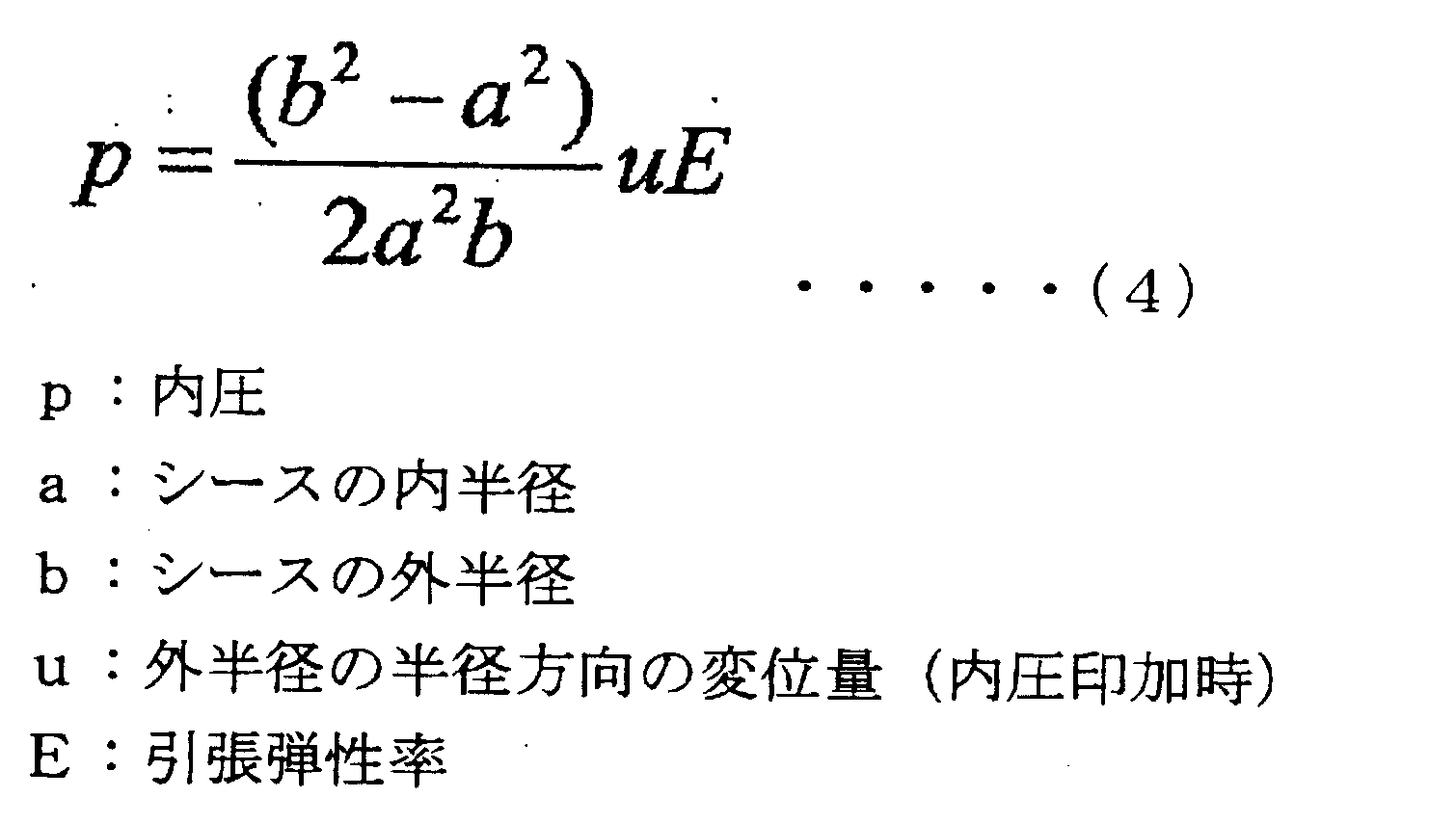
- the internal pressure p of the sheath 6 pressure on the inner surface side of the sheath 6 when the test body 8 obtained by cutting the optical fiber cable 1 is immersed in water in the water tank 9 is 3, based on the dimensions and physical properties of the sheath 6 shown in FIG. 3 (inner radius a, outer radius b, displacement u of the outer radius when applying internal pressure, and tensile modulus E of the sheath 6 (based on JIS K7161)), It can be estimated using equation (4).
- the outer diameter of the specimen 8 measured after immersing the specimen 8 (length 30 cm) whose dimensions were measured in advance in water (temperature 80 ° C.) in the water tank 9 for 2000 hours was used. Can be calculated.
- the internal pressure of the sheath which is increased by immersing a general optical fiber cable in water, is about 0.04 to 0.1 MPa.
- Equation (5) the maximum stress ⁇ (MPa) of the inner surface of the sheath when pure water is immersed in the sheath can be expressed by Equation (5) based on the hoop stress model of the thin cylinder.
- ⁇ p (D ⁇ t) / 2t (5) (P: internal pressure, D: sheath outer diameter, t: sheath thickness)
- FIG. 4 shows a second example of the optical fiber cable of the present invention, and has the same configuration as the first example shown in FIG. 1 except that a tear string 7 is provided.
- the tear string 7 is provided on the inner surface side of the sheath 6, and is attached vertically in the longitudinal direction of the slot core 2.
- a tear string 7 is formed by a tear string 7, which is a recess having an inner surface shape corresponding to the outer surface shape of the tear string 7.
- the tear string 7 enables the sheath 6 to be cut in the longitudinal direction for the purpose of intermediate post-branching.
- an aramid fiber, a PBO fiber, or the like can be used as the tear string 7, an aramid fiber, a PBO fiber, or the like can be used.
- the tear string mark 10 formed on the inner surface of the sheath 6 greatly affects the sheath crack. That is, it was found that when the internal pressure increases, the stress concentrates on the tear string mark 10, so that a sheath crack occurs even if the value of the stress ⁇ shown in the equation (5) is small.
- ⁇ ′ K ⁇ p (D ⁇ t) / 2t (7) (D: sheath outer diameter, t: sheath thickness, p: internal pressure, K: stress concentration factor)
- ⁇ ′ K ⁇ p (D ⁇ t) / 2t ⁇ Yield point strength of sheath material (8)
- the present inventor evaluated the stress concentration when the concave portion is formed on the inner surface of the sheath by FEM (finite element method).
- the stress concentration coefficient K in the above equation (7) is expressed by the following equation (9). We found that it can be approximated.
- the sheath 6 is given sufficient strength against the pressure increase due to water immersion, Breakage of the sheath 6 can be reliably prevented. That is, based on the equations (8) and (9), it is possible to design the sheath 6 to have strength without increasing the outer diameter D and prevent breakage. Moreover, since it is sufficient to select a sheath material within a range satisfying the equations (8) and (9) as a reference, the range of material selection is widened, and the cost can be suppressed.
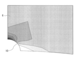
- FIGS. 6 and 7 are diagrams showing FEM (finite element method) analysis results on the stress distribution of the sheath 6 in a model in which pressure (hoop stress) is applied to the sheath 6 having the tear string mark 10 from the inner surface 6a side. is there.
- FIG. 6 is a diagram of a four-divided portion of the cross section of the sheath 6 including the tear string mark 10, and
- FIG. 7 is an enlarged view of the main part of FIG. 6. 6 and 7, the larger the stress generated when the internal pressure is applied, the deeper the stress is, and the smaller the stress, the lighter the screen is displayed.
- the sheath 6 When twisted fibers are used for the tear string 7, the sheath 6 can be torn without causing fraying. However, since the shape of the tear string 7 does not collapse, a tear string mark 10 formed on the inner surface of the sheath 6 is formed. Deeply formed. On the other hand, the tear string 7 made of untwisted fibers is reduced in thickness (flattened) when the sheath 6 is formed, so that the tear string mark 10 is formed shallow.
- the tear string mark 10 when using a tear string 7 formed of a twisted fiber made of generally used aramid fiber, the tear string mark 10 becomes a concave part having a semicircular cross section with a depth of about 0.2 mm, When the tear string 7 formed of untwisted fibers made of PBO fibers is used, the tear string mark 10 is a concave portion having a circular arc shape with a depth of about 0.1 mm.
- the tear string 7 made of untwisted fibers can be made shallow and the stress concentration factor K can be reduced (see equation (9)), thereby reducing the risk of sheath cracking.
- the tear string 7 that does not contain a twist there is a concern that the strength of the tear string 7 may decrease due to fraying when the sheath 6 is torn, but by using a high-strength fiber, the tear string Function can be ensured.
- Example 1 The following verification test was performed using the optical fiber cable 1 having the structure shown in FIG. 4 (the outer diameter of the slot core 2 is 19 mm).
- the water-absorbing tape includes a water-absorbing tape A in which the internal pressure p when immersed in pure water is about 0.08 MPa, and the internal pressure p when immersed in pure water is about 0.00.
- Either of the water absorption tapes B used as 04 MPa was used.
- the water absorption tapes A and B both have a running length of 40 m or less in a water running test in seawater.
- the tear string 7 either a twisted tear string A made of aramid fibers or a tear string B made of PBO fibers having a higher strength than the tear string A and not twisted was used.
- the depth d of the tear string mark 10 was 0.2 mm.
- the depth d of the tear string mark 10 was 0.1 mm.
- the sheath 6 any one of four types of resins A to D having different tensile yield strength (80 ° C.) (yield point strength: JIS K 7113 compliant) was used.
- the thickness t of the sheath 6 was set to any one of 1.2 mm, 1.7 mm, and 2.0 mm with an index of obtaining sufficient mechanical strength as an optical fiber cable.
- the test body 8 (length 30 cm) obtained by cutting the optical fiber cable 1 was immersed in pure water at a temperature of 80 ° C.
- the immersion time was 2000 hours, and the presence or absence of a sheath crack was examined.
- Table 1 the case where the sheath crack did not occur was marked with ⁇ , and the case where it occurred was marked with ⁇ .
- ⁇ ′ was calculated based on Equation (7).
- Example 2 shows the results of a verification test similar to that of Example 1 using the optical fiber cable 1 having the same configuration as that of Example 1 except that there is no tear string 7.
- the sheath 6 any one of seven types of resins A to G having different tensile yield strength (80 ° C.) (yield point strength: JIS K 7113 compliant) was used.
- the thickness t of the sheath 6 was selected in the range of 0.5 to 2.0 mm, using as an index to obtain sufficient mechanical strength as an optical fiber cable.
- ⁇ was calculated based on the formula (5).
Landscapes
- Physics & Mathematics (AREA)
- General Physics & Mathematics (AREA)
- Optics & Photonics (AREA)
- Optical Fibers, Optical Fiber Cores, And Optical Fiber Bundles (AREA)
- Insulated Conductors (AREA)
Abstract
ケーブルコアの外周に吸水テープ層が形成され、その外周にシースが設けられた光ファイバケーブル。シース内部に純水が浸水したときのシース内面の最大応力σが次の式(1)に示す関係を満たす。 σ=p(D-t)/2t < シース材の降伏点強度 ・・・(1) (ただし、D:シース外径、t:シース厚さ、p:シースの内面側の圧力)
Description
本発明は、光ファイバケーブル、特に、耐久性に優れた光ファイバケーブルに関する。
本願は、2009年6月11日に日本に出願された特願2009-140215号に基づき優先権を主張し、その内容をここに援用する。
本願は、2009年6月11日に日本に出願された特願2009-140215号に基づき優先権を主張し、その内容をここに援用する。
防水性を高めた光ファイバケーブルの一例を、図1を利用して説明する。
ここに示す光ファイバケーブル1は、スロットコア2に形成されたスロット溝3に光ファイバテープ心線の集合体4が収容され、スロットコア2の外周に吸水テープ層5が形成され、その外周にシース6が設けられた構成である。
吸水テープ層5を構成する吸水テープとしては、例えば基布に、高吸水性樹脂からなる吸水性パウダーを付着させたものが使用できる。吸水性パウダーは、浸水時に膨潤してケーブル内の空隙を埋め、浸水の拡大を防ぐ機能を有する。
ここに示す光ファイバケーブル1は、スロットコア2に形成されたスロット溝3に光ファイバテープ心線の集合体4が収容され、スロットコア2の外周に吸水テープ層5が形成され、その外周にシース6が設けられた構成である。
吸水テープ層5を構成する吸水テープとしては、例えば基布に、高吸水性樹脂からなる吸水性パウダーを付着させたものが使用できる。吸水性パウダーは、浸水時に膨潤してケーブル内の空隙を埋め、浸水の拡大を防ぐ機能を有する。
しかしながら、吸水性パウダーの膨潤はケーブル内の圧力を高めるため、内圧上昇によるシース7の破損を防ぐことが必要となる。
シース破損を防止するには、シースの強度を高めることが有効である。
シース強度を高めるにはシースを厚く形成することが考えられるが、シースを厚くすればケーブル外径が大きくなり、コストアップや取り扱い性の問題が生じる。また、近年では細径のケーブルが要望されることも多いため、シースを厚く形成することは問題が多い。
シース破損を防止するには、シースの強度を高めることが有効である。
シース強度を高めるにはシースを厚く形成することが考えられるが、シースを厚くすればケーブル外径が大きくなり、コストアップや取り扱い性の問題が生じる。また、近年では細径のケーブルが要望されることも多いため、シースを厚く形成することは問題が多い。
管状体の耐久性向上技術としては、特許文献1~3に示すものがあるが、これらを光ファイバケーブルに適用するには次のような問題がある。
特許文献1には、耐久性に優れたパイプ材料が提案されているが、この材料はシース材料には不向きである。特許文献2には、高い耐久性を示す管状体用の樹脂材料が挙げられているが、この材料をシースに採用すると、ケーブル外径が大きくなりすぎ、コスト面でも不利となる。特許文献3には、パイプの補強構造が示されているが、これもケーブル外径およびコストの点で問題がある。
特許文献1には、耐久性に優れたパイプ材料が提案されているが、この材料はシース材料には不向きである。特許文献2には、高い耐久性を示す管状体用の樹脂材料が挙げられているが、この材料をシースに採用すると、ケーブル外径が大きくなりすぎ、コスト面でも不利となる。特許文献3には、パイプの補強構造が示されているが、これもケーブル外径およびコストの点で問題がある。
本発明は、上記事情に鑑みてなされたもので、ケーブル外径を大きくすることなく浸水時におけるシースの破損を防止でき、コスト面でも問題がない光ファイバケーブルを提供することを目的とする。
本発明の請求項1にかかる光ファイバケーブルは、ケーブルコアの外周に吸水テープ層が形成され、その外周にシースが設けられた光ファイバケーブルであって、シース内面側に純水が浸水したときのシース内面の最大応力σが次の式(1)に示す関係を満たす光ファイバケーブルである。
σ=p(D-t)/2t < シース材の降伏点強度 ・・・(1)
(ただし、D:シースの外径、t:シース厚さ、p:シースの内面側の圧力)
本発明の請求項2にかかる光ファイバケーブルは、ケーブルコアの外周に吸水テープ層が形成され、その外周にシースが設けられ、前記シースの内面側に引き裂き紐が設けられた光ファイバケーブルであって、前記シースの内面には、前記引き裂き紐によって凹部が形成されており、シース内面側に純水が浸水したときのシース内面の最大応力σ’が次の式(2)、(3)に示す関係を満たす光ファイバケーブルである。
σ’=K・p(D-t)/2t < シース材の降伏点強度 ・・・(2)
K≒50×d/t ・・・(3)
(ただし、D:シースの外径、t:シース厚さ、p:シースの内面側の圧力、d:前記凹部の深さ)
本発明の請求項3にかかる光ファイバケーブルは、請求項2において、前記引き裂き紐が、撚りが入っていない繊維からなる光ファイバケーブルである。
σ=p(D-t)/2t < シース材の降伏点強度 ・・・(1)
(ただし、D:シースの外径、t:シース厚さ、p:シースの内面側の圧力)
本発明の請求項2にかかる光ファイバケーブルは、ケーブルコアの外周に吸水テープ層が形成され、その外周にシースが設けられ、前記シースの内面側に引き裂き紐が設けられた光ファイバケーブルであって、前記シースの内面には、前記引き裂き紐によって凹部が形成されており、シース内面側に純水が浸水したときのシース内面の最大応力σ’が次の式(2)、(3)に示す関係を満たす光ファイバケーブルである。
σ’=K・p(D-t)/2t < シース材の降伏点強度 ・・・(2)
K≒50×d/t ・・・(3)
(ただし、D:シースの外径、t:シース厚さ、p:シースの内面側の圧力、d:前記凹部の深さ)
本発明の請求項3にかかる光ファイバケーブルは、請求項2において、前記引き裂き紐が、撚りが入っていない繊維からなる光ファイバケーブルである。
本発明によれば、浸水時におけるシース内面の最大応力とシース材料の強度との関係式に基づいた設計を行うことによって、浸水による圧力上昇に対する十分な強度をシースに与え、浸水時におけるシースの破損を確実に防止できる。
また、上記関係式に基づいて、外径を大きくすることなくシース破損を防止する設計が可能となる。
さらに、上記関係式を基準として、これを満たす範囲でシース材料を選定すればよいため、コストを抑えることができる。
また、上記関係式に基づいて、外径を大きくすることなくシース破損を防止する設計が可能となる。
さらに、上記関係式を基準として、これを満たす範囲でシース材料を選定すればよいため、コストを抑えることができる。
以下、本発明の一実施形態を、図面を参照して説明する。
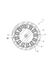
図1は、本発明の第1の例である光ファイバケーブル1を示す断面図である。
ここに示す光ファイバケーブル1は、スロットコア2(ケーブルコア)に形成されたスロット溝3に光ファイバテープ心線の集合体4が収容され、スロットコア2の外周に吸水テープ層5が形成され、その外周にシース6が設けられた構成である。
図1は、本発明の第1の例である光ファイバケーブル1を示す断面図である。
ここに示す光ファイバケーブル1は、スロットコア2(ケーブルコア)に形成されたスロット溝3に光ファイバテープ心線の集合体4が収容され、スロットコア2の外周に吸水テープ層5が形成され、その外周にシース6が設けられた構成である。
吸水テープ層5を構成する吸水テープとしては、例えばポリエステル等からなる基布に、高吸水性樹脂からなる吸水性パウダーを付着させたものを用いることができる。デンプン系,ポリアクリル酸系などの高吸水性樹脂からなるテープを用いてもよい。高吸水性樹脂からなるパウダーおよびテープは、浸水時に膨潤してケーブル内の空隙を埋め、浸水の拡大を防ぐ機能を有する。
シース6の材料には、ポリエチレン、ポリ塩化ビニルなどの樹脂を使用できる。シース6は、材料の選択や可塑剤等の添加剤によりその物性を設定できる。
シース6の材料には、ポリエチレン、ポリ塩化ビニルなどの樹脂を使用できる。シース6は、材料の選択や可塑剤等の添加剤によりその物性を設定できる。
管状体の内圧(内面側の圧力)は、内半径、外半径、外径の変位量、および管状体の引張弾性率で表すことができる。
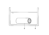
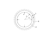
このため、図2に示すように、光ファイバケーブル1を切断して得られた試験体8を水槽9内の水に浸漬したときのシース6の内圧p(シース6の内面側における圧力)は、図3に示すシース6の各寸法および物性(内半径a、外半径b、内圧印加時の外半径の変位量u、およびシース6の引張弾性率E(JIS K7161準拠))に基づいて、式(4)を用いて推定できる。
内圧印加時の変位量は、あらかじめ寸法を測定した試験体8(長さ30cm)を、水槽9内の水(温度80℃)に2000時間浸漬させた後に測定した試験体8の外径を用いて算出できる。
このため、図2に示すように、光ファイバケーブル1を切断して得られた試験体8を水槽9内の水に浸漬したときのシース6の内圧p(シース6の内面側における圧力)は、図3に示すシース6の各寸法および物性(内半径a、外半径b、内圧印加時の外半径の変位量u、およびシース6の引張弾性率E(JIS K7161準拠))に基づいて、式(4)を用いて推定できる。
内圧印加時の変位量は、あらかじめ寸法を測定した試験体8(長さ30cm)を、水槽9内の水(温度80℃)に2000時間浸漬させた後に測定した試験体8の外径を用いて算出できる。
なお、一般的な光ファイバケーブルを水に浸漬させることにより高められたシースの内圧は、0.04~0.1MPa程度となる。
本発明者は、肉薄円筒のフープ応力モデルをもとに、シース内部に純水が浸水したときのシース内面の最大応力σ(MPa)が、式(5)で表すことができることを見出した。
σ=p(D-t)/2t ・・・(5)
(p:内圧、D:シース外径、t:シース厚さ)
σ=p(D-t)/2t ・・・(5)
(p:内圧、D:シース外径、t:シース厚さ)
式(5)より、シース内面の最大応力は、内圧が高くなるほど、またシース6が薄いほど大きくなり、これによってシース割れが起きやすくなることがわかる。
このことから、次に示す式(6)を満たすようなシース材料を選択することによって、浸水による圧力上昇に対する十分な強度をシース6に与え、浸水時におけるシース6の破損を確実に防止できることがわかる。
このことから、次に示す式(6)を満たすようなシース材料を選択することによって、浸水による圧力上昇に対する十分な強度をシース6に与え、浸水時におけるシース6の破損を確実に防止できることがわかる。
σ=p(D-t)/2t < シース材の降伏点強度 ・・・(6)
(D:シース外径、t:シース厚さ、p:内圧)
(D:シース外径、t:シース厚さ、p:内圧)
式(6)に基づけば、外径D(mm)を大きくすることなくシース6に強度を与え、破損を防止する設計が可能となる。
また、式(6)を基準として、これを満たす範囲でシース材料を選定すればよいため、材料選択の幅が広くなり、コストを抑えることができる。
また、式(6)を基準として、これを満たす範囲でシース材料を選定すればよいため、材料選択の幅が広くなり、コストを抑えることができる。
図4は、本発明の光ファイバケーブルの第2の例を示すもので、引き裂き紐7が設けられていること以外は、図1に示す第1の例と同じ構成である。
引き裂き紐7はシース6の内面側に設けられ、スロットコア2の長手方向に縦添えされている。
シース6の内面には、引き裂き紐7によって、引き裂き紐7の外面形状に即した内面形状を有する凹部である引き裂き紐痕10が形成されている。
引き裂き紐7は、中間後分岐などの目的でシース6を長手方向に切断することを可能とするものである。引き裂き紐7としては、アラミド繊維、PBO繊維などが使用できる。
引き裂き紐7はシース6の内面側に設けられ、スロットコア2の長手方向に縦添えされている。
シース6の内面には、引き裂き紐7によって、引き裂き紐7の外面形状に即した内面形状を有する凹部である引き裂き紐痕10が形成されている。
引き裂き紐7は、中間後分岐などの目的でシース6を長手方向に切断することを可能とするものである。引き裂き紐7としては、アラミド繊維、PBO繊維などが使用できる。
本発明者の検討の結果、シース6内面に形成された引き裂き紐痕10がシース割れに大きく影響することがわかった。すなわち、内圧が大きくなると、引き裂き紐痕10に応力が集中することにより、式(5)に示す応力σの値が小さくてもシース割れが起きることがわかった。
引き裂き紐痕10における応力集中を考慮に入れると、シース内面の最大応力σ’は、式(7)で表すことができる。
σ’=K・p(D-t)/2t ・・・(7)
(D:シース外径、t:シース厚さ、p:内圧、K:応力集中係数)
(D:シース外径、t:シース厚さ、p:内圧、K:応力集中係数)
すなわち、シース6内面に引き裂き紐痕10がある場合には、引き裂き紐痕10に応力集中が生じるため、シース割れが発生しない条件は以下の通りとなる。
σ’=K・p(D-t)/2t < シース材の降伏点強度 ・・・(8)
σ’=K・p(D-t)/2t < シース材の降伏点強度 ・・・(8)
本発明者は、FEM(有限要素法)によって、シース内面に凹部が形成されている場合の応力集中を評価したところ、上記式(7)における応力集中係数Kは、次の式(9)で近似できることを見出した。
K≒50×d/t ・・・(9)
(d:引き裂き紐痕の深さ、t:シース厚さ)
(d:引き裂き紐痕の深さ、t:シース厚さ)
従って、上記式(8)、(9)を満たすようなシース材料を選択することによって、引き裂き紐痕10がある場合においても、浸水による圧力上昇に対する十分な強度をシース6に与え、浸水時におけるシース6の破損を確実に防止できる。
すなわち、式(8)、(9)に基づけば、外径Dを大きくすることなくシース6に強度を与え、破損を防止する設計が可能となる。
また、式(8)、(9)を基準として、これを満たす範囲でシース材料を選定すればよいため、材料選択の幅が広くなり、コストを抑えることができる。
すなわち、式(8)、(9)に基づけば、外径Dを大きくすることなくシース6に強度を与え、破損を防止する設計が可能となる。
また、式(8)、(9)を基準として、これを満たす範囲でシース材料を選定すればよいため、材料選択の幅が広くなり、コストを抑えることができる。
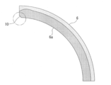
図6および図7は、引き裂き紐痕10を有するシース6に内面6a側から圧力(フープ応力)を加えるモデルにおいて、シース6の応力分布についてのFEM(有限要素法)による解析結果を示す図である。図6は、引き裂き紐痕10を含むシース6断面の4分割部分の図であり、図7は、図6の要部を拡大した図である。
図6および図7においては、内圧印加時に生じた応力が大きいほど濃く、応力が小さいほど薄く表示されている。
図6および図7においては、内圧印加時に生じた応力が大きいほど濃く、応力が小さいほど薄く表示されている。
引き裂き紐7に撚り入り繊維を用いると、ほつれを生じさせずにシース6の引き裂きを行うことができるが、引き裂き紐7の形状が崩れないため、シース6内面に形成される引き裂き紐痕10が深く形成される。
一方、撚りのない繊維からなる引き裂き紐7は、シース6形成時に厚さが小さくなる(扁平化する)ため、引き裂き紐痕10は浅く形成される。
例えば、一般に使用されるアラミド繊維からなる撚り入り繊維で形成した引き裂き紐7を使用した場合には、引き裂き紐痕10は深さ0.2mm程度の断面半円状の凹部となるのに対し、PBO繊維からなる撚りのない繊維で形成した引き裂き紐7を用いた場合には、引き裂き紐痕10は深さ0.1mm程度の断面円弧状の凹部となる。
一方、撚りのない繊維からなる引き裂き紐7は、シース6形成時に厚さが小さくなる(扁平化する)ため、引き裂き紐痕10は浅く形成される。
例えば、一般に使用されるアラミド繊維からなる撚り入り繊維で形成した引き裂き紐7を使用した場合には、引き裂き紐痕10は深さ0.2mm程度の断面半円状の凹部となるのに対し、PBO繊維からなる撚りのない繊維で形成した引き裂き紐7を用いた場合には、引き裂き紐痕10は深さ0.1mm程度の断面円弧状の凹部となる。
このため、撚りのない繊維からなる引き裂き紐7を用いることによって、引き裂き紐痕を浅くし、応力集中係数Kを小さくできることから(式(9)参照)、シース割れの危険を低減できることがわかる。
なお、撚りが入っていない引き裂き紐7を用いる場合には、シース6を引き裂く際のほつれによって引き裂き紐7の強度が低下することが懸念されるが、強度の高い繊維を用いることによって、引き裂き紐としての機能を確保することができる。
なお、撚りが入っていない引き裂き紐7を用いる場合には、シース6を引き裂く際のほつれによって引き裂き紐7の強度が低下することが懸念されるが、強度の高い繊維を用いることによって、引き裂き紐としての機能を確保することができる。
(実施例1)
図4に示す構造の光ファイバケーブル1(スロットコア2の外径19mm)を用いて次の検証試験を行った。
表1に示すように、吸水テープとしては、純水に浸漬させたときの上記内圧pが約0.08MPaとなる吸水テープAと、純水に浸漬させたときの上記内圧pが約0.04MPaとなる吸水テープBのうちいずれかを使用した。なお、吸水テープA、Bは、いずれも海水における水走り試験で走水長40m以下となるものである。
図4に示す構造の光ファイバケーブル1(スロットコア2の外径19mm)を用いて次の検証試験を行った。
表1に示すように、吸水テープとしては、純水に浸漬させたときの上記内圧pが約0.08MPaとなる吸水テープAと、純水に浸漬させたときの上記内圧pが約0.04MPaとなる吸水テープBのうちいずれかを使用した。なお、吸水テープA、Bは、いずれも海水における水走り試験で走水長40m以下となるものである。
引き裂き紐7としては、アラミド繊維からなる撚り入りの引き裂き紐Aと、引き裂き紐Aより高強度のPBO繊維からなる、撚りが入っていない引き裂き紐Bのうちいずれかを使用した。
引き裂き紐Aを用いた場合には引き裂き紐痕10の深さdは0.2mmとなった。引き裂き紐Bを用いた場合は引き裂き紐痕10の深さdは0.1mmとなった。
シース6には、引張降伏強度(80℃)(降伏点強度:JIS K 7113準拠)が異なる4種類の樹脂A~Dのうちいずれかを使用した。シース6の厚さtは、光ファイバケーブルとして十分な機械的強度を得ることを指標として、1.2mm、1.7mm、2.0mmのうちいずれかとした。
引き裂き紐Aを用いた場合には引き裂き紐痕10の深さdは0.2mmとなった。引き裂き紐Bを用いた場合は引き裂き紐痕10の深さdは0.1mmとなった。
シース6には、引張降伏強度(80℃)(降伏点強度:JIS K 7113準拠)が異なる4種類の樹脂A~Dのうちいずれかを使用した。シース6の厚さtは、光ファイバケーブルとして十分な機械的強度を得ることを指標として、1.2mm、1.7mm、2.0mmのうちいずれかとした。
図2に示すように、光ファイバケーブル1を切断して得られた試験体8(長さ30cm)を温度80℃の純水に浸漬した。浸漬時間は2000時間とし、シース割れの有無を調べた。結果を表1および図5に示す。
表1では、シース割れが発生しなかった場合を○とし、発生した場合を×とした。Kは式(9)(K=50×d/t)に基づいて算出した。σ’は式(7)に基づいて算出した。
図5におけるL1は「σ’=シース材の降伏点強度」を示すラインである。
表1では、シース割れが発生しなかった場合を○とし、発生した場合を×とした。Kは式(9)(K=50×d/t)に基づいて算出した。σ’は式(7)に基づいて算出した。
図5におけるL1は「σ’=シース材の降伏点強度」を示すラインである。

表1および図5より、シース内面の最大応力σ’が上記式(8)、(9)に示す関係を満たす場合、すなわち「σ’<シース材の降伏点強度」であるときにはシース割れが起こらず、この関係が満たされない場合にはシース割れが起きたことがわかる。
(実施例2)
図1に示すように、引き裂き紐7がないこと以外は実施例1と同様の構成の光ファイバケーブル1を用いて、実施例1と同様の検証試験を行った結果を表2に示す。
シース6には、引張降伏強度(80℃)(降伏点強度:JIS K 7113準拠)が異なる7種類の樹脂A~Gのうちいずれかを使用した。シース6の厚さtは、光ファイバケーブルとして十分な機械的強度を得ることを指標として、0.5~2.0mmの範囲で選択した。σは式(5)に基づいて算出した。
図1に示すように、引き裂き紐7がないこと以外は実施例1と同様の構成の光ファイバケーブル1を用いて、実施例1と同様の検証試験を行った結果を表2に示す。
シース6には、引張降伏強度(80℃)(降伏点強度:JIS K 7113準拠)が異なる7種類の樹脂A~Gのうちいずれかを使用した。シース6の厚さtは、光ファイバケーブルとして十分な機械的強度を得ることを指標として、0.5~2.0mmの範囲で選択した。σは式(5)に基づいて算出した。
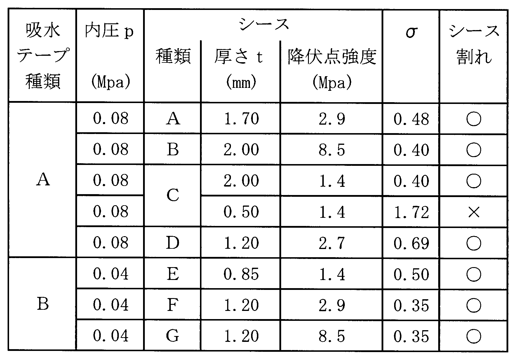
表2より、シース内面の最大応力σが上記式(6)に示す関係を満たす場合、すなわち「σ<シース材の降伏点強度」であるときにはシース割れが起こらず、この関係が満たされない場合にはシース割れが起きたことがわかる。
1 光ファイバケーブル
2 スロットコア(ケーブルコア)
5 吸水テープ層
6 シース
7 引き裂き紐
10 引き裂き紐痕(凹部)
2 スロットコア(ケーブルコア)
5 吸水テープ層
6 シース
7 引き裂き紐
10 引き裂き紐痕(凹部)
Claims (3)
- ケーブルコアの外周に吸水テープ層が形成され、その外周にシースが設けられた光ファイバケーブルであって、
シース内面側に純水が浸水したときのシース内面の最大応力σが次の式(1)に示す関係を満たすことを特徴とする光ファイバケーブル。
σ=p(D-t)/2t < シース材の降伏点強度 ・・・(1)
(ただし、D:シースの外径、t:シース厚さ、p:シースの内面側の圧力) - ケーブルコアの外周に吸水テープ層が形成され、その外周にシースが設けられ、前記シースの内面側に引き裂き紐が設けられた光ファイバケーブルであって、
前記シースの内面には、前記引き裂き紐によって凹部が形成されており、
シース内面側に純水が浸水したときのシース内面の最大応力σ’が次の式(2)、(3)に示す関係を満たすことを特徴とする光ファイバケーブル。
σ’=K・p(D-t)/2t < シース材の降伏点強度 ・・・(2)
K≒50×d/t ・・・(3)
(ただし、D:シースの外径、t:シース厚さ、p:シースの内面側の圧力、d:前記凹部の深さ) - 前記引き裂き紐は、撚りが入っていない繊維からなることを特徴とする請求項2に記載の光ファイバケーブル。
Applications Claiming Priority (2)
| Application Number | Priority Date | Filing Date | Title |
|---|---|---|---|
| JP2009-140215 | 2009-06-11 | ||
| JP2009140215 | 2009-06-11 |
Publications (1)
| Publication Number | Publication Date |
|---|---|
| WO2010143440A1 true WO2010143440A1 (ja) | 2010-12-16 |
Family
ID=43308701
Family Applications (1)
| Application Number | Title | Priority Date | Filing Date |
|---|---|---|---|
| PCT/JP2010/003878 Ceased WO2010143440A1 (ja) | 2009-06-11 | 2010-06-10 | 光ファイバケーブル |
Country Status (3)
| Country | Link |
|---|---|
| JP (1) | JP4955798B2 (ja) |
| TW (1) | TW201113573A (ja) |
| WO (1) | WO2010143440A1 (ja) |
Citations (3)
| Publication number | Priority date | Publication date | Assignee | Title |
|---|---|---|---|---|
| JPH0268817A (ja) * | 1988-09-05 | 1990-03-08 | Mitsubishi Petrochem Co Ltd | 走水防止スロットリボン型ケーブル |
| JPH04222261A (ja) * | 1990-12-25 | 1992-08-12 | Showa Electric Wire & Cable Co Ltd | 吸水テープおよび防水型光ファイバケーブル |
| JP2000241686A (ja) * | 1999-02-22 | 2000-09-08 | Fujikura Ltd | テープ−スロット型光ケーブル |
Family Cites Families (1)
| Publication number | Priority date | Publication date | Assignee | Title |
|---|---|---|---|---|
| JP2007212523A (ja) * | 2006-02-07 | 2007-08-23 | Sumitomo Electric Ind Ltd | 光ケーブル |
-
2010
- 2010-06-09 JP JP2010132168A patent/JP4955798B2/ja active Active
- 2010-06-10 TW TW099118885A patent/TW201113573A/zh unknown
- 2010-06-10 WO PCT/JP2010/003878 patent/WO2010143440A1/ja not_active Ceased
Patent Citations (3)
| Publication number | Priority date | Publication date | Assignee | Title |
|---|---|---|---|---|
| JPH0268817A (ja) * | 1988-09-05 | 1990-03-08 | Mitsubishi Petrochem Co Ltd | 走水防止スロットリボン型ケーブル |
| JPH04222261A (ja) * | 1990-12-25 | 1992-08-12 | Showa Electric Wire & Cable Co Ltd | 吸水テープおよび防水型光ファイバケーブル |
| JP2000241686A (ja) * | 1999-02-22 | 2000-09-08 | Fujikura Ltd | テープ−スロット型光ケーブル |
Also Published As
| Publication number | Publication date |
|---|---|
| TW201113573A (en) | 2011-04-16 |
| JP2011018036A (ja) | 2011-01-27 |
| JP4955798B2 (ja) | 2012-06-20 |
Similar Documents
| Publication | Publication Date | Title |
|---|---|---|
| JP5719052B1 (ja) | 光ケーブル | |
| US10228529B2 (en) | Cable having core, jacket and polymeric jacket access features located in the jacket | |
| US8582940B2 (en) | Fiber optic cables with extruded access features and methods of making fiber optic cables | |
| JP6618744B2 (ja) | 光ファイバケーブル、光ファイバケーブルの製造方法および製造装置 | |
| NZ582884A (en) | Telecommunication cable equipped with tight-buffered optical fibers | |
| CN105556367A (zh) | 铠装光纤电缆 | |
| CN110504063A (zh) | 用于分布式光纤水听系统的光电复合缆 | |
| JP5290547B2 (ja) | 複合ケーブル | |
| WO2010074167A1 (ja) | 光ファイバケーブル | |
| JP2010139631A (ja) | 光ファイバケーブル | |
| JP4955798B2 (ja) | 光ファイバケーブルの設計方法 | |
| JP2009181119A (ja) | 光ケーブル | |
| JP5840902B2 (ja) | ルースチューブ型光ファイバケーブル | |
| CN101369472A (zh) | 给光单元提供余长的海底光电复合缆填充条 | |
| US8483532B2 (en) | Low adhesion plastic-cladding optical fiber | |
| CN204575916U (zh) | 非金属铠装增强型自承式光缆 | |
| CN107916587A (zh) | 一种高强度防裂绳缆 | |
| JP2005189390A (ja) | 光ファイバ心線 | |
| CN206833039U (zh) | 一种室外室内用多芯铠装光缆 | |
| CN218003803U (zh) | 一种光缆复合材料加强芯 | |
| JP2010128169A (ja) | 光ファイバケーブル | |
| JP5158840B2 (ja) | 光ファイバケーブル | |
| CN111443448A (zh) | 一种环形加强件抗压光缆 | |
| CN206546732U (zh) | 一种海洋勘探用光纤电缆 | |
| AU2015255303B2 (en) | Fiber optic cables with extruded access features and methods of making fiber optic cables |
Legal Events
| Date | Code | Title | Description |
|---|---|---|---|
| 121 | Ep: the epo has been informed by wipo that ep was designated in this application |
Ref document number: 10785972 Country of ref document: EP Kind code of ref document: A1 |
|
| NENP | Non-entry into the national phase |
Ref country code: DE |
|
| 122 | Ep: pct application non-entry in european phase |
Ref document number: 10785972 Country of ref document: EP Kind code of ref document: A1 |