WO2010143286A1 - 通信端末、アドレス解決サーバ、及びコンピュータプログラム - Google Patents
通信端末、アドレス解決サーバ、及びコンピュータプログラム Download PDFInfo
- Publication number
- WO2010143286A1 WO2010143286A1 PCT/JP2009/060614 JP2009060614W WO2010143286A1 WO 2010143286 A1 WO2010143286 A1 WO 2010143286A1 JP 2009060614 W JP2009060614 W JP 2009060614W WO 2010143286 A1 WO2010143286 A1 WO 2010143286A1
- Authority
- WO
- WIPO (PCT)
- Prior art keywords
- address
- communication terminal
- network
- bundle
- host
- Prior art date
- Legal status (The legal status is an assumption and is not a legal conclusion. Google has not performed a legal analysis and makes no representation as to the accuracy of the status listed.)
- Ceased
Links
Images





Classifications
-
- H—ELECTRICITY
- H04—ELECTRIC COMMUNICATION TECHNIQUE
- H04L—TRANSMISSION OF DIGITAL INFORMATION, e.g. TELEGRAPHIC COMMUNICATION
- H04L45/00—Routing or path finding of packets in data switching networks
-
- H—ELECTRICITY
- H04—ELECTRIC COMMUNICATION TECHNIQUE
- H04L—TRANSMISSION OF DIGITAL INFORMATION, e.g. TELEGRAPHIC COMMUNICATION
- H04L61/00—Network arrangements, protocols or services for addressing or naming
- H04L61/09—Mapping addresses
- H04L61/10—Mapping addresses of different types
- H04L61/103—Mapping addresses of different types across network layers, e.g. resolution of network layer into physical layer addresses or address resolution protocol [ARP]
-
- H—ELECTRICITY
- H04—ELECTRIC COMMUNICATION TECHNIQUE
- H04L—TRANSMISSION OF DIGITAL INFORMATION, e.g. TELEGRAPHIC COMMUNICATION
- H04L61/00—Network arrangements, protocols or services for addressing or naming
- H04L61/09—Mapping addresses
- H04L61/25—Mapping addresses of the same type
- H04L61/2503—Translation of Internet protocol [IP] addresses
- H04L61/256—NAT traversal
- H04L61/2567—NAT traversal for reachability, e.g. inquiring the address of a correspondent behind a NAT server
-
- H—ELECTRICITY
- H04—ELECTRIC COMMUNICATION TECHNIQUE
- H04L—TRANSMISSION OF DIGITAL INFORMATION, e.g. TELEGRAPHIC COMMUNICATION
- H04L61/00—Network arrangements, protocols or services for addressing or naming
- H04L61/09—Mapping addresses
- H04L61/25—Mapping addresses of the same type
- H04L61/2503—Translation of Internet protocol [IP] addresses
- H04L61/256—NAT traversal
- H04L61/2582—NAT traversal through control of the NAT server, e.g. using universal plug and play [UPnP]
-
- H—ELECTRICITY
- H04—ELECTRIC COMMUNICATION TECHNIQUE
- H04L—TRANSMISSION OF DIGITAL INFORMATION, e.g. TELEGRAPHIC COMMUNICATION
- H04L61/00—Network arrangements, protocols or services for addressing or naming
- H04L61/45—Network directories; Name-to-address mapping
- H04L61/4505—Network directories; Name-to-address mapping using standardised directories; using standardised directory access protocols
- H04L61/4511—Network directories; Name-to-address mapping using standardised directories; using standardised directory access protocols using domain name system [DNS]
-
- H—ELECTRICITY
- H04—ELECTRIC COMMUNICATION TECHNIQUE
- H04L—TRANSMISSION OF DIGITAL INFORMATION, e.g. TELEGRAPHIC COMMUNICATION
- H04L61/00—Network arrangements, protocols or services for addressing or naming
- H04L61/09—Mapping addresses
- H04L61/25—Mapping addresses of the same type
- H04L61/2503—Translation of Internet protocol [IP] addresses
- H04L61/2521—Translation architectures other than single NAT servers
- H04L61/2535—Multiple local networks, e.g. resolving potential IP address conflicts
Definitions
- the present invention is, for example, a communication terminal that communicates with a counterpart terminal, and particularly belongs to the same network as the network to which the communication terminal belongs, or directly or via a network and a router to which the communication terminal belongs.
- control information such as a host address, etc.
- a computer program for causing a computer to function as such a communication terminal or address resolution server.
- an IP address is used as an address for identifying a communication terminal as a transmission source and a counterpart terminal as a transmission destination.
- a method for assigning a unique host name to the communication terminal and the counterpart terminal and performing communication using the host name is known.
- a DNS Domain Name System
- the IP address is converted into an IP address, and the converted IP address of the counterpart terminal is notified to the communication terminal. Thereafter, the communication terminal performs communication with the counterpart terminal by designating the converted IP address of the counterpart terminal as a transmission destination address. Accordingly, the user of the communication terminal can perform communication with the counterpart terminal using only the host name that is relatively easy for the user to identify.
- IP addresses include global addresses and local addresses.
- the global address is a globally unique address.
- the local address is an address uniquely determined in a specific communication network.
- a general network has a hierarchical network configuration in which a plurality of local networks using local addresses exist in the global network using global addresses. In this case, the following technical problem may occur in the communication using the host name described above.
- a server A having a local address “10.0.0.123” and a host name “AA” and a terminal A having a local address “10.0.030” are included.
- the local network has a NAT (Network) whose LAN side address (that is, local address) is “10.0.0.1” and WAN side address (that is, global address) is “123.45.67.89”. Address Translation)
- a DNS server having a global address of “141.140.139.138” is arranged in the global network through a router
- terminal A has a host name.
- the terminal A obtains an IP address for accessing the server A from the DNS server by presenting the host name “AA” and accessing the DNS server.
- the DNS server since the DNS server only performs conversion from the host name to the global address, “123.45.67.89”, which is the WAN side address of the NAT router included in the local network to which the server A belongs, The terminal A is notified as an IP address for accessing the server A. Thereafter, the terminal A sets “123.45.67.89” received from the DNS server as a transmission destination address, and then starts data transmission.
- the data transmitted from the terminal A is transmitted to the NAT router.
- the transmission destination of the data transmitted from the terminal A is the WAN side address of the NAT router, the NAT router recognizes that the data transmitted from the terminal A is transmitted to itself. As a result, data transmitted from the terminal A to the server A is not transmitted to the server A.
- Patent Document 1 discloses a configuration in which a unique DNS server is installed in each local network.
- Patent Document 2 discloses a configuration in which a relay center that converts a global address converted from a host name into a local address in a global network is further disclosed.
- the present invention has been made in view of the above-described conventional problems, for example, between a communication terminal capable of performing communication with different terminals relatively easily and at a relatively low cost, and between different terminals. It is an object of the present invention to provide an address resolution server capable of performing the above communication relatively easily and at a relatively low cost, and a computer program that causes a computer to function as such a communication terminal or an address resolution server.
- a communication terminal includes a counterpart terminal belonging to the same network, or belonging to another network connected directly or indirectly via a router, and the counterpart A communication terminal that performs communication using a host name unique to the terminal, and transmits the control information necessary for performing communication with the counterpart terminal to the address resolution server of the counterpart terminal
- Recognizing means for recognizing a positional relationship on the network between the communication terminal and the counterpart terminal based on a first address bundle indicating a network route to reach the counterpart terminal; Based on the recognized positional relationship on the network between the communication terminal and the counterpart terminal, a host used for communication with the counterpart terminal from the second address bundle acquired by the acquisition means Determining means for determining an address.
- the address resolution server is configured such that a communication terminal belongs to the same network as the network to which the communication terminal belongs or is connected to the network to which the communication terminal belongs via a router.
- An address resolution server for transmitting control information necessary for communication with a counterpart terminal belonging to a network network to be communicated using a host name unique to the counterpart terminal, the global network to which the address resolution server belongs.
- storage means for storing an address bundle indicating a network route from the network to the counterpart terminal, and the address Transmitting means for transmitting the bundle as the control information to the communication terminal.
- a first computer program of the present invention is a computer program for controlling a computer provided in a communication terminal of the present invention, and the computer includes the acquisition unit, the recognition unit, and the computer. It functions as a determination means.
- a second computer program of the present invention is a computer program for controlling a computer provided in an address resolution server of the present invention, and the computer is used as the storage means and the transmission means. Make it work.
- Embodiments according to the communication terminal of the present invention include a counterpart terminal belonging to the same network, or belonging to another network connected directly or indirectly via a router, and the counterpart terminal A communication terminal that performs communication using a host name, and presents the host name of the counterpart terminal to an address resolution server that transmits control information necessary for communication with the counterpart terminal
- the acquisition means for acquiring, as the control information, a second address bundle indicating a network route from the address resolution server to the counterpart terminal from the global network network to which the address resolution server belongs, From the global network to which the second address bundle acquired by the acquiring means and the address resolution server belong, the communication terminal Recognizing means for recognizing a positional relationship on the network between the communication terminal and the counterpart terminal based on a first address bundle indicating a network route to the communication path, and the communication recognized by the recognizing means Determination of determining a host address to be used for communication with the counterpart terminal from the second address bundle acquired by the acquisition means based on a positional relationship on
- communication for example, data transmission
- the counterpart terminal may belong to the same network as the network to which the communication terminal belongs.
- the partner terminal belongs to a network network directly connected via a router to the network network to which the communication terminal belongs (that is, a network network in which one router is interposed between the network network to which the communication terminal belongs). It may be.
- the counterpart terminal may be a network network indirectly connected via a router to the network network to which the communication terminal belongs (that is, a plurality of routers intervene between the network network to which the communication terminal belongs or another network It may belong to a network (internet network).
- the communication terminal particularly includes an acquisition unit, a recognition unit, and a determination unit in order to communicate with the counterpart terminal.
- the obtaining means obtains the second address bundle corresponding to the host name of the counterpart terminal from the address resolution server by presenting the host name of the counterpart terminal to the address resolution server.
- the “address resolution server” according to the present embodiment is intended to indicate a server that converts a host name into an address bundle. Such an address resolution server eliminates the need for the communication terminal (or the user of the communication terminal) to recognize the host address of the counterpart terminal in advance.
- the “address bundle” according to the present embodiment is a broad meaning meaning information indicating a network route from the global network network to which the address resolution server belongs to a terminal (that is, a communication terminal or a partner terminal). Any information may be used as long as the network path can be specified.
- the “address bundle” is an address of various devices and various terminals existing in a network path from the global network network to which the address resolution server belongs to a terminal (that is, a communication terminal or a partner terminal). It is an address bundle including a group (for example, a host address such as an IP address or a device address such as a MAC address).
- the recognizing means includes the communication terminal based on each of the second address bundle acquired by the acquiring means and the first address bundle indicating the network path from the global network to which the address resolution server belongs to the communication terminal. Recognize the positional relationship on the network with the other terminal. Specifically, for example, the recognition unit recognizes the positional relationship between the network network to which the communication terminal belongs and the network network to which the counterpart terminal belongs.
- the first address bundle used for the operation of the recognition unit may be acquired from the address resolution server by the operation of the acquisition unit described above. Or you may acquire by the operation
- the determination means determines the host address (that is, the data transmission destination and the host address) used for communication with the counterpart terminal. Host address). Specifically, for example, when the recognition unit recognizes that the communication terminal and the counterpart terminal belong to the same network, the host terminal of the counterpart terminal is used as it is to communicate with the counterpart terminal. Can be done. Therefore, in this case, the determining means determines the host address of the counterpart terminal as the host address used for communication with the counterpart terminal. Alternatively, if the recognition means recognizes that the communication terminal and the counterpart terminal belong to different network networks, it is not possible to communicate with the counterpart terminal simply by using the host address of the counterpart terminal. it is conceivable that.
- the determination means uses the host address (for example, WAN side host address) of the router located in the network to which the partner terminal belongs for the communication with the partner terminal. Determine as an address.
- the determining unit can appropriately perform communication with the counterpart terminal according to the positional relationship. Can be determined.
- the communication terminal can suitably perform communication with the counterpart terminal.
- software for performing the above-described operation on the address resolution server is incorporated, and software for performing the above-described operation on a terminal (that is, a communication terminal or a partner terminal)
- a terminal that is, a communication terminal or a partner terminal
- the above-described operation can be performed. Therefore, it is possible to receive a very advantageous effect in practice that it is not necessary to introduce new hardware to the existing network. That is, it is possible to receive a very advantageous effect in practice that a communication terminal (and further an address resolution server) that performs the above-described operation can be introduced at low cost.
- the first address bundle is an upper side of a router existing in a network path from the global network network to which the address resolution server belongs to the communication terminal.
- the second address bundle includes a host address and a host address of the communication terminal in the order of the network path, and the second address bundle is a router existing in the network path from the global network network to which the address resolution server belongs to the partner terminal.
- a host address of the host terminal included in the first address bundle and a host address included in the second address bundle In order from the upper side to the lower side of the network path By compare, recognizing the positional relationship on the network between the communication terminal and said other terminal.
- the first address bundle includes the upper host address of the router and the host address of the communication terminal that exist in the network path from the global network to which the address resolution server belongs to the communication terminal. Address bundles arranged in order from the side closer to the resolution server or from the side farther from the address resolution server are included.
- the second address bundle the higher-order host address of the router and the host address of the partner terminal existing in the network path from the global network to which the address resolution server belongs to the partner terminal are address resolution. Address bundles arranged in order from the side closer to the server or from the side farther from the address resolution server are included. That is, each address bundle includes addresses in a format corresponding to the hierarchical structure of the network.
- the recognition means can preferably recognize the positional relationship on the network between the communication terminal and the counterpart terminal.
- the recognizing unit can preferably recognize to what level the communication terminal and the counterpart terminal belong to the same network.
- the recognition unit includes: When the host address of a predetermined layer among the host addresses included in the first address bundle and the host address of the predetermined layer among the host addresses included in the second address bundle are the same, The host address of the next layer of the predetermined layer among the host addresses included in one address bundle is compared with the host address of the next layer of the predetermined layer among the host addresses included in the second address bundle. You may comprise.
- the recognition means can preferably recognize to what level the communication terminal and the counterpart terminal belong to the same network. Specifically, for example, if the host address in the same layer (for example, the host address on the upper side of the router) is the same, the recognition means indicates that the communication terminal and the partner terminal belong to the same network up to that layer. Can be recognized. Therefore, in this case, the recognizing unit further compares the host addresses of the next layer (the lower layer or the layer away from the address resolution server). On the other hand, if the host addresses of the same layer are different, the recognition means can recognize from the layer that the communication terminal and the counterpart terminal belong to different network networks.
- the recognizing means can recognize from the hierarchy that the router located on the upper side of the communication terminal and the router located on the upper side of the counterpart terminal belong to different network networks. Therefore, in this case, if the upper host address of the router located on the upper side of the counterpart terminal is determined as an address used for communication with the counterpart terminal, communication with the counterpart terminal can be suitably performed. .
- the determination unit includes: If the host address of a predetermined layer among the host addresses included in the first address bundle differs from the host address of the predetermined layer among the host addresses included in the second address bundle, the second address The host address of the predetermined layer among the host addresses included in the bundle may be determined as a host address used for communication with the counterpart terminal.
- the recognition means can recognize from the layer that the communication terminal and the counterpart terminal belong to different network networks. That is, the recognizing means can recognize from the hierarchy that the router located on the upper side of the communication terminal and the router located on the upper side of the counterpart terminal belong to different network networks. Therefore, if the higher-order host address of the router located on the higher-order side of the counterpart terminal is determined as an address used for communication with the counterpart terminal, communication with the counterpart terminal can be suitably performed.
- the address bundle investigated by the communication terminal itself can be registered in the address resolution server. For this reason, the above-described operation using the address bundle can be suitably performed.
- a router existing in the network path from the global network to which the address resolution server belongs to the communication terminal corresponds to UPnP (Universal Plug and Play).
- the investigating unit uses the UPnP command for the lower host address of the first router, which is the router located on the side closest to the communication terminal, so that the upper host of the first router.
- an address bundle containing the host address of the signal terminal to the network path order may be configured to be registered in the address resolution server as said first address bundle.
- the communication terminal itself can suitably investigate the address bundle, as will be described in detail later with reference to a specific example.
- the address bundle investigated by the communication terminal itself can be registered in the address resolution server. For this reason, the above-described operation using the address bundle can be suitably performed.
- the investigating unit obtains the upper host address of the first router by using the UPnP command, there exists the second router that is the router belonging to the upper network of the first router.
- the investigating means firstly (i) switches the operation mode of the first router to the bridge mode, and the communication terminal itself on the network network to which the second router belongs from the second router.
- DHCP Dynamic Host Configuration Protocol
- An address bundle further including a side host address may be registered in the address resolution server as the first address bundle.
- the communication terminal can be used even when a plurality of routers exist in the network path between the global network to which the address resolution server belongs and the communication terminal. It is possible for itself to investigate the address bundle suitably. As a result, the address bundle investigated by the communication terminal itself can be registered in the address resolution server. For this reason, the above-described operation using the address bundle can be suitably performed.
- the investigation means belongs to the global network network to which the address resolution server belongs and investigates the network route to the communication terminal.
- the registration means includes an address bundle including the host address of the higher-order host address and the host address of the communication terminal acquired from the address investigation server in the order of the network path.
- the first address bundle You may be configured to be registered.
- an address bundle including the upper host address of the router obtained by the operation of the external address investigation server is registered in the address resolution server. Can do. For this reason, the above-described operation using the address bundle can be suitably performed.
- the registration unit includes an address bundle including the lower-order host address of the router and the host address of the communication terminal in the network path order, the first address bundle.
- the registration unit includes the lower-order host address of the router, the host address of the communication terminal, and the device address unique to the communication terminal in the network path order.
- An address bundle may be registered as the first address bundle.
- the investigation unit requests another communication terminal located on the upper side of the router to obtain the upper host address of the router.
- the registration means may be configured to register an address bundle including the higher-order host address obtained from the other communication terminal and the host address of the communication terminal in the network route order as the first address bundle. Good.
- an address bundle including a higher-order host address of a router obtained by the operation of another external communication terminal is registered in the address resolution server. be able to. For this reason, the above-described operation using the address bundle can be suitably performed.
- the acquisition unit acquires the first address bundle as the control information from the address resolution server.
- the first address bundle can be obtained from the address resolution server, the first address bundle can be obtained relatively easily.
- a router interposed between the other communication terminals in response to a request from another communication terminal belonging to a network network lower than the network network to which the communication terminal belongs. And a notification means for notifying the other communication terminal of the acquired higher-order address.
- the address bundle including the higher-order host address of the router acquired by itself is addressed to the address resolution server as an address bundle corresponding to another communication terminal. You can register. For this reason, the above-described operation using the address bundle can be suitably performed.
- a communication network is a network network in which a communication terminal belongs to the same network network as the network to which the communication terminal belongs or is connected to each other via a router and a network to which the communication terminal belongs.
- An address resolution server for transmitting control information necessary for communication using a host name unique to the partner terminal and the partner terminal belonging to the partner terminal from the global network to which the address resolution server belongs.
- Storage means for storing an address bundle indicating a network route to the terminal on the side, and the control of the address bundle in response to an address resolution request from the communication terminal presenting the host name of the counterpart terminal Transmitting means for transmitting to the communication terminal as information.
- the address bundle stored in the storage means (that is, the address bundle corresponding to the counterpart terminal) is a communication terminal that is trying to communicate with the counterpart terminal. Can be sent to. Therefore, the communication terminal can determine the host address used for communication with the counterpart terminal as described above. As a result, the various effects described above can be suitably enjoyed.
- the embodiment of the address resolution server of the present invention can also adopt various aspects.
- the address bundle is a higher-order host address of the router existing in a network path from the global network to which the address resolution server belongs to the counterpart terminal or
- the lower-order host address and the host address of the counterpart terminal are included in the network path order.
- the communication terminal can receive the upper host address (for example, WAN side host address) of the router included in the first address bundle and the upper host address (for example, WAN side) of the router included in the second address bundle.
- Host address or the host address of the communication terminal and the host address of the counterpart terminal, to properly recognize the positional relationship on the network between the communication terminal and the counterpart terminal. be able to.
- a first embodiment relating to a computer program of the present invention is a computer program for controlling a computer provided in the above-described embodiment (including various aspects thereof) relating to a communication terminal of the present invention. , Functioning as the acquisition means, the recognition means, and the determination means.
- the computer program of the present invention if the computer program is read from a recording medium such as a ROM, a CD-ROM, a DVD-ROM, and a hard disk that stores the computer program, the computer program is executed.
- a recording medium such as a ROM, a CD-ROM, a DVD-ROM, and a hard disk that stores the computer program
- the computer program is executed.
- the computer program is executed after being downloaded to a computer via communication means, the above-described embodiment of the communication terminal of the present invention can be realized relatively easily.
- the first embodiment of the computer program of the present invention can also adopt various aspects.
- a second embodiment according to the computer program of the present invention is a computer program for controlling a computer provided in the above-described embodiment (including various aspects thereof) according to the address resolution server of the present invention.
- a computer provided in the above-described embodiment (including various aspects thereof) according to the address resolution server of the present invention.
- the computer program of the present invention if the computer program is read from a recording medium such as a ROM, a CD-ROM, a DVD-ROM, and a hard disk storing the computer program and then executed by the computer.
- a recording medium such as a ROM, a CD-ROM, a DVD-ROM, and a hard disk storing the computer program and then executed by the computer.
- the computer program is executed after being downloaded to a computer via communication means, the above-described embodiment of the address resolution server of the present invention can be realized relatively easily.
- the second embodiment of the computer program of the present invention can also adopt various aspects.
- the first embodiment according to the computer program product of the present invention clearly embodies program instructions that can be executed by a computer provided in the above-described embodiments (including various aspects thereof) of the communication terminal of the present invention.
- the computer is caused to function as the acquisition unit, the recognition unit, and the determination unit.
- the computer program product of the present invention if the computer program product is read into a computer from a recording medium such as a ROM, CD-ROM, DVD-ROM, or hard disk that stores the computer program product, Alternatively, for example, if the computer program product, which is a transmission wave, is downloaded to a computer via communication means, the above-described embodiment of the communication terminal of the present invention can be implemented relatively easily. More specifically, the computer program product may be configured by computer-readable code (or computer-readable instructions) that functions as the embodiment of the communication terminal of the present invention described above.
- the first embodiment of the computer program product of the present invention can also adopt various aspects.
- the second embodiment relating to the computer program product of the present invention clearly embodies program instructions executable by a computer provided in the above-described embodiment (including various aspects thereof) relating to the address resolution server of the present invention. And the computer is caused to function as the storage unit and the transmission unit.
- the computer program product if the computer program product is read into a computer from a recording medium such as a ROM, CD-ROM, DVD-ROM, or hard disk storing the computer program product, Alternatively, for example, if the computer program product, which is a transmission wave, is downloaded to a computer via communication means, the above-described embodiment of the address resolution server of the present invention can be implemented relatively easily. More specifically, the computer program product may be configured by computer-readable code (or computer-readable instructions) that functions as the above-described embodiment of the address resolution server of the present invention.
- the second embodiment of the computer program product of the present invention can also adopt various aspects.
- the acquisition unit, the recognition unit, and the determination unit are provided.
- the storage unit and the transmission unit are provided.
- a computer is functioned as embodiment which concerns on the communication terminal of this invention.
- the computer is caused to function as an embodiment of the address resolution server of the present invention. Therefore, communication between different terminals can be performed relatively easily and at a relatively low cost.
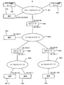
- FIG. 1 is a block diagram conceptually showing the overall configuration of the communication system 1 according to this embodiment.
- the communication system 1 includes a plurality of communication terminals 100 (specifically, a communication terminal 100a, a communication terminal 100b, a communication terminal 100c, a communication terminal 100d, and a communication) that transmit and receive data.
- a terminal 100 e) an address resolution server 200 that converts a host name into an address bundle 221 and transmits the address bundle 221 to the communication terminal 100 in response to an address resolution request from the communication terminal 100, and a plurality of networks that connect different networks
- a NAT router 300 (specifically, a NAT router 300a, a NAT router 300b, and a NAT router 300c).
- These devices constitute a global network 401 and a local network 402 (specifically, a local network 402a, a local network 402b, and a local network 402c).
- the global network 401 and the local network 402 may take either a wired or wireless form, some of which may be wired and the other part wireless. Further, it may be a dedicated line, a general public line or a telephone line, a packet network, or a circuit switching network.
- the global network 401 or the local network 402 may be any network as long as it can transmit and receive data.
- the global network 401 is connected to a communication terminal 100 a having a global IP address “98.76.54.32” and a host name “A”, and the address resolution server 200.
- a NAT router 300a whose global IP address on the WAN side is “123.45.67.89” is connected to the global network 401 via a network port on the WAN side.
- a communication terminal 100b having a local IP address “192.168.0.3” and a host name “B” is connected to the local network 402a.
- a NAT router 300a whose local IP address on the LAN side is “192.168.0.1” is connected to the local network 402a via a network port on the LAN side.
- a NAT router 300b whose local IP address on the WAN side is “192.168.0.2” is connected to the local network 402a via a network port on the WAN side.
- a NAT router 300c whose WAN-side local IP address is “192.168.0.9” is connected to the local network 402a via a WAN-side network port.
- the local IP address is “192.168.1.99” and the host name is “C”, and the local IP address is “192.168.1.1”.
- a communication terminal 100d having a host name “D” is connected.
- a NAT router 300b whose local IP address on the LAN side is “192.168.1.1” is connected to the local network 402b via a network port on the LAN side.
- a communication terminal 100e having a local IP address “192.168.1.100” and a host name “E” is connected to the local network 402c. Further, a NAT router 300c whose local IP address on the LAN side is “192.168.1.1” is connected to the local network 402c via a network port on the LAN side.
- An example of such a communication system 1 is a communication system provided in an apartment house such as an apartment.
- the global network 401 corresponds to the Internet
- the local network 402a corresponds to the local network of the entire apartment
- each of the local networks 402b and 402c corresponds to the local network of each room in the apartment.
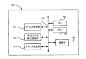
- FIG. 2 is a block diagram conceptually showing the basic structure of the communication terminal 100 included in the communication system 1 according to the present embodiment.
- the communication terminal 100 includes an address acquisition unit 101 that constitutes a specific example of “acquisition means” in the present invention, and a network configuration recognition unit that constitutes a specific example of “recognition means” in the present invention. 102, an address determination unit 103, a CPU 104, a memory 105, and a communication unit 106, which constitute a specific example of “determination means” in the present invention.
- the address acquisition unit 101 acquires the address bundle 221 corresponding to the communication terminal 100 serving as the communication partner from the address resolution server 200 by presenting the host name of the communication terminal 100 serving as the communication partner to the address resolution server 200. To do.
- the address bundle 221 will be described in detail later (see FIG. 4).
- the network configuration recognition unit 102 determines the positional relationship on the network between the communication terminal 100 itself and the communication terminal 100 that is the communication partner (in other words, the position in the communication system). Investigate and recognize the relationship). Details of the operation of the network configuration recognition unit 102 will be described later (see FIG. 5 and FIG. 9).
- the address determination unit 103 uses an IP address (that is, an IP address of a data transmission destination) used for communication with the communication terminal 100 as a communication partner. To decide. The details of the operation of the address determination unit 103 will be described later (see FIGS. 5 and 9).
- the CPU 104 is connected to the address acquisition unit 101, the network configuration recognition unit 102, the address determination unit 103, and the communication unit 106 via the bus 110, and controls the entire communication terminal 100 by giving instructions to various control means. .
- software or firmware for operating the CPU 104 is stored in the memory 105.
- the memory 105 is used in general data processing in the communication terminal 100.
- the memory 105 includes a ROM area in which a program (that is, a firmware program) for performing the operation as the communication terminal 100 is stored, and data is temporarily stored or necessary for operations such as the firmware program. It consists of a RAM area where variables are stored.
- the communication unit 106 controls communication (for example, communication using HTTP or the like) via the global network 401 or the local network 402 performed by the communication terminal 100.
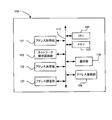
- FIG. 3 is a block diagram conceptually showing the basic structure of the address resolution server 200 provided in the communication system 1 according to this embodiment.
- the address resolution server 200 includes an address management table storage unit 201 that constitutes a specific example of “storage means” in the present invention, and an address that constitutes a specific example of “transmission means” in the present invention.
- a transmission unit 202, a CPU 203, a memory 204, and a communication unit 205 are provided.
- the address management table storage unit 201 stores an address management table 220 including an address bundle 221 corresponding to each of the plurality of communication terminals 100 included in the communication system 1.
- Such an address management table storage unit 201 is typically configured to include a recording medium such as a hard disk or a semiconductor memory.
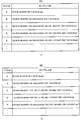
- FIG. 4 is a data structure diagram conceptually showing the address management table 220.
- the address management table 220 includes an address bundle 221 corresponding to each of the plurality of communication terminals 100 included in the communication system 1. More specifically, the address management table 220 includes an address bundle 221 corresponding to the communication terminal 100a, an address bundle 221 corresponding to the communication terminal 100b, an address bundle 221 corresponding to the communication terminal 100c, and the communication terminal 100d. A corresponding address bundle 221 and an address bundle 221 corresponding to the communication terminal 100e are included.
- the address bundle 221 includes information that can specify a network path from the global network 401 to which the address management server 200 belongs to the communication terminal 100. Specifically, for example, the address bundle 221 includes the WAN side IP address of the NAT router 300 existing on the network path from the global network 401 to which the address management server 200 belongs to the communication terminal 100 and the communication terminal 100. An IP address is included.
- the network path from the global network 401 to which the address management server 200 belongs to the communication terminal 100a includes the address management server 200 and the communication terminal 100a.
- the address bundle 221 corresponding to the communication terminal 100a includes “98.76.54.32”, which is the global IP address of the communication terminal 100a.
- the address bundle 221 corresponding to the communication terminal 100a includes “55555” that is a port number used for communication by the communication terminal 100a in addition to the global IP address of the communication terminal 100a. Yes.
- the address bundle 221 corresponding to the communication terminal 100a includes a data array of “98.76.54.32:55555”.
- the network path from the global network 401 to which the address management server 200 belongs to the communication terminal 100b includes the address management server 200, the NAT router 300a, and the communication terminal 100b. Therefore, the address bundle 221 corresponding to the communication terminal 100b includes “123.45.67.89” which is the global IP address on the WAN side of the NAT router 300a and “192.168.168” which is the local IP address of the communication terminal 100b. .0.3 ". Further, these addresses are included in the address bundle 221 in a state in which they are arranged in order from the upper side to the lower side of the network path from the global network 401 to which the address management server 200 belongs to the communication terminal 100b. It is.
- the address bundle 221 corresponding to the communication terminal 100b includes “123.45.67.89”, which is the global IP address on the WAN side of the NAT router 300a, and “192.168 .. 0.3 "is included so as to be arranged in this order.
- the address bundle 221 corresponding to the communication terminal 100b is used when the NAT router 300a transfers communication to the communication terminal 100b in addition to the WAN-side global IP address of the NAT router 300a.
- the port number “40000” is included so as to be associated with the global IP address on the WAN side of the NAT router 300a.
- the address bundle 221 corresponding to the communication terminal 100b in addition to the local IP address of the communication terminal 100b, “54321” which is the port number used for communication by the communication terminal 100b is added to the local IP address of the communication terminal 100b. Included to be associated. Accordingly, the address bundle 221 corresponding to the communication terminal 100b includes a data array of “123.45.67.89:40000 ⁇ 192.168.0.3:54321”.
- the network path from the global network 401 to which the address management server 200 belongs to the communication terminal 100c includes the address management server 200, the NAT router 300a, and the NAT router 300b communication terminal 100c. Therefore, the address bundle 221 corresponding to the communication terminal 100c includes “123.45.67.89”, which is the global IP address on the WAN side of the NAT router 300a, and “Local IP address on the WAN side of the NAT router 300b”. 192.168.0.2 ”and“ 192.168.1.99 ”which is the local IP address of the communication terminal 100c are included.
- these addresses are included in the address bundle 221 in a state in which they are arranged in order from the upper side to the lower side of the network path from the global network 401 to which the address management server 200 belongs to the communication terminal 100c.
- the address bundle 221 corresponding to the communication terminal 100b includes “123.45.67.89” that is the global IP address on the WAN side of the NAT router 300a and “192” that is the local IP address on the WAN side of the NAT router 300b. .168.0.2 ”and“ 192.168.1.99 ”which is the local IP address of the communication terminal 100c are included so as to be arranged in this order.
- the address bundle 221 corresponding to the communication terminal 100c is used when the NAT router 300a transfers communication to the communication terminal 100c in addition to the WAN-side global IP address of the NAT router 300a.
- the port number “40001” is included so as to be associated with the WAN-side global IP address of the NAT router 300a.
- the port number used when the NAT router 300b transfers communication to the communication terminal 100c is “44444”. Is included so as to be associated with the local IP address on the WAN side of the NAT router 300b.
- the address bundle 221 corresponding to the communication terminal 100c in addition to the local IP address of the communication terminal 100c, “54321” which is the port number used for communication by the communication terminal 100c is added to the local IP address of the communication terminal 100c. Included to be associated. Accordingly, the address bundle 221 corresponding to the communication terminal 100c includes a data array of “123.45.67.89:400001-192.168.0.2:44444-192.168.1.99:54321”. Yes.
- the network path from the global network 401 to which the address management server 200 belongs to the communication terminal 100d includes the address management server 200, the NAT router 300a, and the NAT router 300b communication terminal 100d. Therefore, the address bundle 221 corresponding to the communication terminal 100d includes “123.45.67.89”, which is the global IP address on the WAN side of the NAT router 300a, and “Local IP address on the WAN side of the NAT router 300b”. 192.168.0.2 ”and“ 192.168.1.100 ”, which is the local IP address of the communication terminal 100d.
- these addresses are included in the address bundle 221 in a state in which they are arranged in order from the upper side to the lower side of the network path from the global network 401 to which the address management server 200 belongs to the communication terminal 100d.
- the address bundle 221 corresponding to the communication terminal 100b includes “123.45.67.89” that is the global IP address on the WAN side of the NAT router 300a and “192” that is the local IP address on the WAN side of the NAT router 300b. .168.0.2 ”and“ 192.168.1.100 ”, which is the local IP address of the communication terminal 100d, are included so as to be arranged in this order.
- the address bundle 221 corresponding to the communication terminal 100d is used when the NAT router 300a transfers communication to the communication terminal 100d in addition to the WAN-side global IP address of the NAT router 300a.
- the port number “40002” is included so as to be associated with the WAN-side global IP address of the NAT router 300a.
- the port number used when the NAT router 300b transfers communication to the communication terminal 100d is “44445”. Is included so as to be associated with the local IP address on the WAN side of the NAT router 300b.
- the address bundle 221 corresponding to the communication terminal 100d in addition to the local IP address of the communication terminal 100d, “54321” which is the port number used for communication by the communication terminal 100d is added to the local IP address of the communication terminal 100d. Included to be associated. Therefore, the address bundle 221 corresponding to the communication terminal 100d includes a data array of “123.45.67.89:40002 ⁇ 192.168.0.2:44445 ⁇ 192.168.1.100:54321”. Yes.
- the network path from the global network 401 to which the address management server 200 belongs to the communication terminal 100e includes the address management server 200, the NAT router 300a, and the NAT router 300c communication terminal 100e. Therefore, the address bundle 221 corresponding to the communication terminal 100e includes “123.45.67.89”, which is the global IP address on the WAN side of the NAT router 300a, and “Local IP address on the WAN side of the NAT router 300c”. 192.168.0.9 ”and“ 192.168.1.100 ”, which is the local IP address of the communication terminal 100e.
- these addresses are included in the address bundle 221 in a state in which they are arranged in order from the upper side to the lower side of the network path from the global network 401 to which the address management server 200 belongs to the communication terminal 100e.
- the address bundle 221 corresponding to the communication terminal 100b includes “123.45.67.89” which is the global IP address on the WAN side of the NAT router 300a and “192” which is the local IP address on the WAN side of the NAT router 300c. .168.0.9 ”and“ 192.168.1.100 ”, which is the local IP address of the communication terminal 100e, are included so as to be arranged in this order.
- the address bundle 221 corresponding to the communication terminal 100b includes “123.45.67.89” which is the global IP address on the WAN side of the NAT router 300a and “192” which is the local IP address on the WAN side of the NAT router 300c. .168.0.9 ”and“ 192.168.1.100 ”, which is the local IP address
- the address bundle 221 corresponding to the communication terminal 100e is used when the NAT router 300a transfers communication to the communication terminal 100e in addition to the WAN-side global IP address of the NAT router 300a.
- the port number “40003” is included so as to be associated with the WAN-side global IP address of the NAT router 300a.
- the port number used when the NAT router 300c transfers communication to the communication terminal 100e is “33333”. Is included so as to be associated with the local IP address on the WAN side of the NAT router 300c.
- the address bundle 221 corresponding to the communication terminal 100e in addition to the local IP address of the communication terminal 100e, “54321” which is the port number used for communication by the communication terminal 100e is added to the local IP address of the communication terminal 100e. Included to be associated. Therefore, the address bundle 221 corresponding to the communication terminal 100e includes a data array of “123.45.67.89:40002 ⁇ 192.168.0.9:33333 ⁇ 192.168.1.100:54321”. Yes.
- the WAN side IP address of the NAT router 300 existing in the network path from the global network 401 to which the address management server 200 belongs to the communication terminal 100 and the communication terminal 100 as the address bundle.
- IP addresses (further, the port numbers used for communication by the communication terminal 100 and the NAT router 300) are included, but as described in detail later, in addition to or instead of these IP addresses and port numbers, Other information (for example, the IP address on the LAN side of the NAT router 300 described later, and the MAC addresses of the communication terminal 100 and the NAT router 300) may be included.
- the address transmission unit 202 extracts a desired address bundle 221 from the address management table 220 stored in the address management table storage unit 201 in response to a request from the communication terminal 100 and extracts the desired address bundle.
- the address bundle 221 is transmitted to the communication terminal 100.
- the CPU 203 is connected to the address management table storage unit 201, the address transmission unit 202, and the communication unit 205 via the bus 210, and controls the entire communication terminal 100 by giving instructions to various control means.
- software or firmware for operating the CPU 203 is stored in the memory 204.
- the memory 204 is used in general data processing in the address management server 200.
- the memory 204 is a ROM area in which a program (that is, a firmware program) for performing the operation as the address management server 200 is stored, and data is temporarily stored or necessary for operations such as a firmware program.
- RAM area for storing various variables.
- the communication unit 205 controls communication (for example, communication using HTTP) via the global network 401 and the local network 402 performed by the address management table 200.
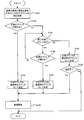
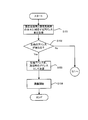
- FIG. 5 is a flowchart conceptually showing a flow of operations of the communication system 1 according to the present embodiment.
- the transmission source communication terminal 100 is operated by the operation of the address acquisition unit 101 provided in the communication terminal 100 (hereinafter referred to as “transmission source communication terminal 100” for convenience).
- Address bundle 221 and address bundle 221 corresponding to data transmission destination communication terminal 100 (hereinafter referred to as “destination communication terminal 100” for convenience) are acquired from address resolution server 200.
- the transmission source communication terminal 100 presents the host name of the transmission destination communication terminal 100 and requests the address resolution server 200 to transmit the address bundle 221 corresponding to the transmission destination communication terminal 100.
- the address transmission unit 202 included in the address resolution server 200 responds to a request from the transmission source communication terminal 100, and an address bundle 221 corresponding to the transmission source communication terminal 100 and an address bundle 221 corresponding to the transmission destination communication terminal 100. Are read from the address management table storage unit 201, and the read address bundle 221 is transmitted to the transmission source communication terminal 100.
- the address check unit 107 (see FIG. 6) and the address check server 500 (see FIG. 8) for the address bundle 221 corresponding to the transmission source communication terminal 100.
- the transmission source communication terminal 100 itself can investigate. Therefore, when the source communication terminal 100 itself examines the address bundle 221 corresponding to the source communication terminal 100, the address bundle 221 corresponding to the source communication terminal 100 is the address in step S101 shown in FIG. It may not be acquired from the resolution server 200. In other words, in step S101 shown in FIG. 5, instead of acquiring the address bundle 221 corresponding to the transmission source communication terminal 100 from the address resolution server 200, the transmission source communication terminal 100 itself becomes the transmission source communication terminal 100. The address bundle 221 corresponding to the transmission source communication terminal 100 may be acquired by investigating the corresponding address bundle 221.
- the IP address that is, the address resolution server 200 (or the address resolution server 200) (or the address resolution server 200) acquired in step S101 corresponding to the transmission source communication terminal 100 acquired in step S101 Whether the IP address closest to the global network 401) to which the address resolution server 200 belongs and the leftmost IP address of the address bundle 221 corresponding to the destination communication terminal 100 acquired in step S101 are different. Determination is made (step S102).
- step S102 If it is determined in step S102 that the leftmost IP address of the address bundle 221 corresponding to the transmission source communication terminal 100 is different from the leftmost IP address of the address bundle 221 corresponding to the transmission destination communication terminal 100 (Step S102: Yes)
- the address determination unit 103 By the operation of the address determination unit 103 provided in the transmission source communication terminal 100, the IP address at the left end of the address bundle 221 corresponding to the transmission destination communication terminal 100 is changed to the transmission destination communication terminal 100 by the transmission source communication terminal 100. It is determined as an IP address used for communication with 100 (step S103). Thereafter, after the IP address determined in step S103 is set as the transmission destination address, data is transmitted from the transmission source communication terminal 100 to the transmission destination communication terminal 100 (step S104).
- step S102 it is determined that the leftmost IP address of the address bundle 221 corresponding to the transmission source communication terminal 100 and the leftmost IP address of the address bundle 221 corresponding to the transmission destination communication terminal 100 are the same.
- the network configuration recognition unit 102 provided in the transmission source communication terminal 100 operates. It is determined whether or not there is a next-stage IP address in each of the address bundles 221 (step S105).
- an IP address following the leftmost IP address (hereinafter referred to as “second stage IP” as appropriate). It is determined whether or not there is an “address”.
- the IP address of the next stage is further included in each of the address bundle 221 corresponding to the transmission source communication terminal 100 and the address bundle 221 corresponding to the transmission destination communication terminal 100.
- IP address is determined to exist (step S105: Yes)
- the second stage of the address bundle 221 corresponding to the source communication terminal 100 is operated by the operation of the network configuration recognition unit 102 included in the source communication terminal 100. It is determined whether the IP address of the eye is different from the IP address of the second stage of the address bundle 221 corresponding to the destination communication terminal 100 (step S106).
- step S106 if the second-stage IP address of the address bundle 221 corresponding to the transmission source communication terminal 100 is different from the second-stage IP address of the address bundle 221 corresponding to the transmission destination communication terminal 100. If it is determined (step S106: Yes), the second stage IP address of the address bundle 221 corresponding to the destination communication terminal 100 is transmitted by the operation of the address determination unit 103 provided in the source communication terminal 100. The original communication terminal 100 is determined as the IP address used for communication with the transmission destination communication terminal 100 (step S103). Thereafter, after the IP address determined in step S107 is set as the transmission destination address, data is transmitted from the transmission source communication terminal 100 to the transmission destination communication terminal 100 (step S104).
- step S106 the second-stage IP address of the address bundle 221 corresponding to the transmission source communication terminal 100 and the second-stage IP address of the address bundle 221 corresponding to the transmission destination communication terminal 100 are obtained. If it is determined that they are different (step S106: No), the process returns to step S105, and the address bundle 221 corresponding to the transmission source communication terminal 100 and the transmission destination communication terminal 100 whose IP address is the target of the determination operation in step S106. Steps S105 and S106 are repeated until there is no address bundle 221 corresponding to.
- the IP address of the next stage of the address bundle 221 corresponding to the source communication terminal 100 (that is, the IP address of the third stage, the IP address of the fourth stage,...) And the destination communication terminal 100. If the IP address of the next stage of the address bundle 221 corresponding to the address bundle 221 is the same, the address decision unit 103 provided in the transmission source communication terminal 100 operates to further increase the address bundle 221 corresponding to the transmission destination communication terminal 100.
- the next-stage IP address is determined as the IP address used for communication between the transmission source communication terminal 100 and the transmission destination communication terminal 100 (step S107). Thereafter, after the IP address determined in step S107 is set as the transmission destination address, data is transmitted from the transmission source communication terminal 100 to the transmission destination communication terminal 100 (step S104).
- step S105 it is determined that there is no further IP address in the next stage in each of the address bundle 221 corresponding to the transmission source communication terminal 100 and the address bundle 221 corresponding to the transmission destination communication terminal 100. If it is determined (step S105: No), the IP address at the left end of the address bundle 221 corresponding to the transmission destination communication terminal 100 is changed to the transmission source communication terminal 100 by the operation of the address determination unit 103 provided in the transmission source communication terminal 100. Is determined as an IP address used for communication with the destination communication terminal 100 (step S108). This operation is preferably performed when the NAT router 300 may be a hairpin compatible router.
- the IP address determined in step S108 is set as the transmission destination address, and data is transmitted from the transmission source communication terminal 100 to the transmission destination communication terminal 100. It is determined whether or not it is possible (step S109). If the NAT router 300 is a hairpin compatible router, data transmission is possible.
- step S109 when it is determined that data can be transmitted from the transmission source communication terminal 100 to the transmission destination communication terminal 100 (step S109: Yes), the data transmission is continued as it is (step S109: Yes). Step S104). On the other hand, as a result of the determination in step S109, if it is determined that data cannot be transmitted from the transmission source communication terminal 100 to the transmission destination communication terminal 100 (step S109: No), the data is not transmitted. End the operation.
- data is transmitted from the communication terminal 100c included in the communication system 1 shown in FIG. 1 to each of the communication terminal 100a, the communication terminal 100b, the communication terminal 100d, and the communication terminal 100e.
- An example of the operation will be described.
- the communication terminal 100c is “123.45.67.89”, which is the leftmost IP address of the address bundle 221 corresponding to the communication terminal 100c, and the IP address of the leftmost of the address bundle 221 corresponding to the communication terminal 100a. 98.76.54.32 ".
- “123.45.67.89” that is the leftmost IP address of the address bundle 221 corresponding to the communication terminal 100c and “98.76.” That is the leftmost IP address of the address bundle 221 corresponding to the communication terminal 100a. 54.32 ”is a different IP address
- the communication terminal 100c communicates“ 98.76.54.32 ”, which is the leftmost IP address of the address bundle 221 corresponding to the communication terminal 100a.
- the communication terminal 100c uses “55555”, which is the port number corresponding to the leftmost IP address of the address bundle 221 corresponding to the communication terminal 100a, so that the communication terminal 100c communicates with the communication terminal 100a. It is determined as a destination port number to be used.
- the communication terminal 100c sets the IP address “98.76.54.32” as the transmission destination address and the port number “55555” as the transmission destination port number, Send data.
- the data transmitted from the communication terminal 100c reaches the communication terminal 100a via the NAT 300b and the NAT 300a. Therefore, it is possible to suitably transmit data from the communication terminal 100c to the communication terminal 100a.
- the communication terminal 100c is “123.45.67.89”, which is the leftmost IP address of the address bundle 221 corresponding to the communication terminal 100c, and “IP” which is the leftmost IP address of the address bundle 221 corresponding to the communication terminal 100b. 123.45.67.89 ".
- “123.45.67.89” which is the leftmost IP address of the address bundle 221 corresponding to the communication terminal 100c and “123.45.” Which is the leftmost IP address of the address bundle 221 corresponding to the communication terminal 100b. Since “67.89” is the same IP address, the communication terminal 100c further compares the IP address of the next stage.
- the communication terminal 100c has “192.168.0.2” that is the second-stage IP address of the address bundle 221 corresponding to the communication terminal 100c and the first address bundle 221 corresponding to the communication terminal 100b.
- the second-stage IP address “192.168.0.3” is compared.
- “192.168.0.2” which is the second-stage IP address of the address bundle 221 corresponding to the communication terminal 100c and “192” which is the leftmost IP address of the address bundle 221 corresponding to the communication terminal 100b. .168.0.3 ” is a different IP address
- the communication terminal 100c changes the second-stage IP address“ 192.168.0.3 ”of the address bundle 221 corresponding to the communication terminal 100b to“ 192.168.0.3 ”.
- the communication terminal 100c is determined as an IP address used for communication with the communication terminal 100b. Furthermore, the communication terminal 100c transmits “54321”, which is the port number corresponding to the second-stage IP address of the address bundle 221 corresponding to the communication terminal 100b, and the communication terminal 100c performs communication with the communication terminal 100b. It is determined as a destination port number used for performing.
- the communication terminal 100c sets the IP address “192.168.0.3” as the transmission destination address and sets the port number “54321” as the transmission destination port number, and then transmits the communication terminal 100b to the communication terminal 100b.
- Send data As a result, the data transmitted from the communication terminal 100c reaches the communication terminal 100b via the NAT 300b. Accordingly, data can be suitably transmitted from the communication terminal 100c to the communication terminal 100b.
- the IP address of the communication terminal 100b obtained by presenting the host name “B” of the communication terminal 100b to the DNS server is the local network 402a to which the communication terminal 100b belongs.
- the global IP address on the WAN side of the NAT router 300a that directly connects the global network 401 to the global network 401 is “123.45.67.89”.
- the communication terminal 100c transmits data to the communication terminal 100b after setting the IP address “123.45.67.89” as the transmission destination address.
- this data reaches the NAT router 300a, it is not transferred from the NAT router 300a to the communication terminal 100b thereafter.
- a DNS server is provided in each local network 402 or a special one is provided. It is necessary to provide a relay center that is hardware.
- data is transmitted from the communication terminal 100c to the communication terminal 100b without providing a DNS server in each local network 402 or a relay center as special hardware.
- software for performing the operation as the address management server 200 described above is incorporated into an existing DNS server, and the operation as the communication terminal 100 is performed with respect to an existing communication terminal. If software is incorporated, the above-described operation can be performed, so that it is possible to enjoy a very advantageous effect in practice that it is not necessary to introduce new hardware to an existing communication system. That is, it is possible to receive a very advantageous effect in practice that the communication terminal 100 and the address resolution server 200 that perform the above-described operation can be introduced at low cost.
- the communication terminal 100c is “123.45.67.89” which is the leftmost IP address of the address bundle 221 corresponding to the communication terminal 100c and the leftmost IP address of the address bundle 221 corresponding to the communication terminal 100d. 123.45.67.89 ".
- “123.45.67.89” that is the leftmost IP address of the address bundle 221 corresponding to the communication terminal 100c and “123.45.” That is the leftmost IP address of the address bundle 221 corresponding to the communication terminal 100d. Since “67.89” is the same IP address, the communication terminal 100c further compares the IP address of the next stage.
- the communication terminal 100c has “192.168.0.2” as the second-stage IP address of the address bundle 221 corresponding to the communication terminal 100c and the first address bundle 221 corresponding to the communication terminal 100d.
- the second-stage IP address “192.168.0.2” is compared.
- “192.168.0.2” which is the second-stage IP address of the address bundle 221 corresponding to the communication terminal 100c
- the second-stage IP address of the address bundle 221 corresponding to the communication terminal 100d Since a certain “192.168.0.2” is the same IP address, the communication terminal 100c further compares the IP address of the next stage.
- the communication terminal 100c includes “192.168.1.99” which is the third-stage IP address of the address bundle 221 corresponding to the communication terminal 100c and the first address bundle 221 corresponding to the communication terminal 100d.
- the third-stage IP address “192.168.1.100” is compared.
- “192.168.1.99” which is the third-stage IP address of the address bundle 221 corresponding to the communication terminal 100c
- the third-stage IP address of the address bundle 221 corresponding to the communication terminal 100d Since a certain “192.168.1.100” is a different IP address, the communication terminal 100c is “192.168.1.100”, which is the third-stage IP address of the address bundle 221 corresponding to the communication terminal 100d.
- the communication terminal 100 "is determined as the IP address used for the communication terminal 100c to communicate with the communication terminal 100d. Furthermore, the communication terminal 100c uses “54321”, which is the port number corresponding to the third-stage IP address of the address bundle 221 corresponding to the communication terminal 100d, and the communication terminal 100c performs communication with the communication terminal 100d. It is determined as a destination port number used for performing.
- the communication terminal 100c sets the IP address “192.168.1.100” as the transmission destination address and sets the port number “54321” as the transmission destination port number, and then transmits the communication terminal 100d to the communication terminal 100d. Send data. As a result, the data transmitted from the communication terminal 100c reaches the communication terminal 100d directly.
- the IP address of the communication terminal 100d obtained by presenting the host name “D” of the communication terminal 100d to the DNS server is the local network 402b to which the communication terminal 100d belongs.
- the communication terminal 100c transmits data to the communication terminal 100d after setting the IP address “123.45.67.89” as the transmission destination address.
- this data reaches the NAT router 300a, it is not transferred from the NAT router 300a to the communication terminal 100d thereafter.
- data is transmitted from the communication terminal 100c to the communication terminal 100d without providing a DNS server in each local network 402 or a relay center as special hardware. Can do. That is, it is possible to receive a very advantageous effect in practice that the communication terminal 100 and the address resolution server 200 that perform the above-described operation can be introduced at low cost.
- the communication terminal 100c is “123.45.67.89”, which is the leftmost IP address of the address bundle 221 corresponding to the communication terminal 100c, and the IP address of the leftmost of the address bundle 221 corresponding to the communication terminal 100e. 123.45.67.89 ".
- “123.45.67.89” that is the leftmost IP address of the address bundle 221 corresponding to the communication terminal 100c and “123.45.” That is the leftmost IP address of the address bundle 221 corresponding to the communication terminal 100e. Since “67.89” is the same IP address, the communication terminal 100c further compares the IP address of the next stage.
- the communication terminal 100c has “192.168.0.2” that is the second-stage IP address of the address bundle 221 corresponding to the communication terminal 100c and the first address bundle 221 corresponding to the communication terminal 100e.
- the second-stage IP address “192.168.0.9” is compared.
- the second-stage IP address “192.168.0.2” of the address bundle 221 corresponding to the communication terminal 100c and the second-stage IP address of the address bundle 221 corresponding to the communication terminal 100e are used. Since a certain “192.168.0.9” is a different IP address, the communication terminal 100 c is “192.168.8.0.” Which is the second-stage IP address of the address bundle 221 corresponding to the communication terminal 100 e.
- the communication terminal 100c transmits “33333” that is the port number corresponding to the second-stage IP address of the address bundle 221 corresponding to the communication terminal 100e, and the communication terminal 100c performs communication with the communication terminal 100e. It is determined as a destination port number used for performing.
- the communication terminal 100c sets the IP address “192.168.0.9” as the transmission destination address and sets the port number “33333” as the transmission destination port number, and then sets the IP address of the communication terminal 100e. Send data. As a result, the data transmitted from the communication terminal 100c reaches the communication terminal 100e via the NAT router 300b and the NAT router 300c.
- the IP address of the communication terminal 100e obtained by presenting the host name “E” of the communication terminal 100e to the DNS server is the local network 403b to which the communication terminal 100e belongs.
- the communication terminal 100c transmits data to the communication terminal 100e after setting the IP address “123.45.67.89” as the transmission destination address.
- this data reaches the NAT router 300a, it is not transferred from the NAT router 300a to the communication terminal 100e thereafter.
- data is transmitted from the communication terminal 100c to the communication terminal 100e without providing a DNS server in each local network 402 or a relay center as special hardware. Can do. That is, it is possible to receive a very advantageous effect in practice that the communication terminal 100 and the address resolution server 200 that perform the above-described operation can be introduced at low cost.
- FIG. 6 is a block diagram conceptually showing the basic structure of the communication terminal 100-1 that executes the first investigation / registration method for the address bundle 221. As shown in FIG. In addition, about the structure same as the communication terminal 100 mentioned above, the same referential mark is attached
- the communication terminal 100-1 is similar to the communication terminal 100 described above, and includes an address acquisition unit 101, a network configuration recognition unit 102, an address determination unit 103, a CPU 104, a memory 105, a communication Part 106.
- the communication terminal 100-1 performs the first investigation / registration method of the address bundle 221 to execute the first investigation / registration method of the address bundle 221 and the address investigation unit 107 constituting one specific example of the “examination means” in the present invention, And an address registration unit 108 constituting a specific example of “means”.
- the NAT router 300 included in the communication system 1 is a UPnP (Universal Plug and Play) compatible router.
- the address bundle 221 is examined by executing the first investigation / registration method.
- the address bundle 221 obtained as a result of the investigation can be stored (that is, registered) in the address management table storage unit 201. Therefore, the following description will be made on the assumption that the NAT router 300 included in the communication system 1 is a UPnP (Universal Plug and Play) compatible router.
- the address examining unit 107 performs the following operation. First, the address examining unit 107 executes a “traceroute” command in which the IP address of the address resolution server 200 is set as an argument. As a result, the address examining unit 107 can acquire the IP address on the LAN side of the NAT router 300 existing on the network path from the global network 401 to which the address resolution server 200 belongs to the communication terminal 100-1.
- the address checking unit 107 uses the UPnP to connect the NAT router 300 closest to the communication terminal 100-1 (hereinafter, the NAT router 300 closest to the communication terminal 100-1 to the “nth stage” as appropriate. Obtain the WAN-side IP address of the NAT router 300 ′′.
- the NAT router 300 is configured to perform sexual routing simultaneously so that a request from the upper side of the NAT router 300 reaches the communication terminal 100-1. Also good.
- the address bundle 221 transmitted to the address resolution server 200 is stored in the address management table storage unit 201 as a part of the address management table 220.
- the address examining unit 107 switches the operation mode of the first-stage NAT router 300 from the router mode to the bridge mode.
- the state of the communication terminal 100-1 is changed from the state where the first-stage NAT router 300 belongs to a network (for example, a local network) serving as a boundary with another network to the first-stage NAT router 300.
- the second-stage NAT router 300 which is positioned one level higher than 300, switches to a state in which it belongs to a network serving as a boundary with another network. That is, the network to which the communication terminal 100-1 and the first stage NAT router 300 belong is integrated with the network to which the second stage NAT router 300 belongs.
- the address investigating unit 107 obtains an IP address in the network to which the second-stage NAT router 300 belongs from the second-stage NAT router 300 using DHCP (Dynamic Host Configuration) Protocol. As a result, the communication terminal 100-1 can access within the network to which the second-stage NAT router 300 belongs.
- DHCP Dynamic Host Configuration
- the address examining unit 107 acquires the WAN side IP address of the second-stage NAT router 300 by the UPnP command.
- the NAT router 300 is configured to perform sexual routing simultaneously so that a request from the upper side of the NAT router 300 reaches the communication terminal 100-1. Also good.
- the address checking unit 107 determines that the k-th stage The operation mode of the first NAT router 300 is switched from the router mode to the bridge mode, and the IP address in the network to which the k + 1-th stage NAT router 300 belongs is changed from the k + 1-th stage NAT router 300 using DHCP.
- the WAN side IP address of the (k + 1) th stage NAT router 300 is acquired.
- the address examining unit 107 sets the operation mode of the first-stage NAT router 300. Switch from bridge mode to router mode. Similarly, when there is no k + 1-th stage NAT router 300 that is one stage higher than the k-th stage (where k is an integer of 2 or more) stage NAT router 300, the address checking unit 107 Each operation mode of the NAT router 300 from the first stage to the first stage is switched from the bridge mode to the router mode.
- the address examining unit 107 acquires the IP address in the network to which the first-stage NAT router 300 belongs from the first-stage NAT router 300 using DHCP. Thereafter, the address examining unit 107 acquires the IP address of the communication terminal 100-1 itself by using the “ipconfig” command.
- the address examining unit 107 is connected to each WAN side of one or a plurality of NAT routers 300 existing in the network path from the global network 401 to which the address resolution server 200 belongs to the communication terminal 100-1.
- the IP address and the IP address of the communication terminal 100-1 can be acquired.
- the IP address of each WAN side of the one or more NAT routers 300 and the IP address of the communication terminal 100-1 obtained in this way are converted into the above-described address bundle 221 format by the operation of the address registration unit 108.
- the address bundle 221 is transmitted to the address resolution server 200 by the operation of the address registration unit 108.
- the address bundle 221 transmitted to the address resolution server 200 is stored in the address management table storage unit 201 as a part of the address management table 220.
- the WAN side IP address is acquired in order from the NAT router 300 located on the side closer to the communication terminal 100-1.
- the WAN side IP address may be acquired in order from the NAT router 300 located on the side far from the communication terminal 100-1 (in other words, located on the side closer to the global network 401).
- the WAN side IP addresses of the k NAT routers 300 are obtained by the following operation. May be.
- the address examining unit 107 executes a “traceroute” command in which the IP address of the address resolution server 200 is set as an argument.
- the address examining unit 107 switches the operation mode of each of the first-stage NAT router 300 to the (k ⁇ 1) -th stage NAT router 300 from the router mode to the bridge mode.
- the address examining unit 107 acquires an IP address in the network to which the k-th stage NAT router 300 belongs from the k-th stage NAT router 300 by using DHCP (Dynamic Host Configuration) Protocol. Thereafter, the address examining unit 107 acquires the WAN-side IP address of the k-th stage NAT router 300 using the UPnP command. Subsequently, the address examining unit 107 switches the operation mode of the NAT router 300 at the (k ⁇ 1) -th stage from the bridge mode to the router mode.
- DHCP Dynamic Host Configuration Protocol
- the address checking unit 107 uses DHCP (Dynamic Host Configuration Configuration Protocol) to obtain an IP address in the network to which the k-1 stage NAT router 300 belongs from the k-1 stage NAT router 300. get. Thereafter, the address examining unit 107 obtains the WAN side IP address of the (k ⁇ 1) -th stage NAT router 300 using the UPnP command. Thereafter, such an operation is repeated until the operation mode of the first-stage NAT router 300 is switched to the router mode. As a result, the address examining unit 107 performs the WAN-side IP address and communication of one or a plurality of NAT routers 300 existing in the network path from the global network 401 to which the address resolution server 200 belongs to the communication terminal 100-1. The IP address of the terminal 100-1 can be acquired.
- DHCP Dynamic Host Configuration Configuration Protocol
- the communication terminal 100c included in the communication system 1 shown in FIG. 1 has the configuration shown in FIG. 6, and the communication terminal 100c (that is, 100-1c) checks the address bundle 221. An example of operation when registering will be described.
- the address examining unit 107 included in the communication terminal 100-1c executes a “traceroute” command in which the IP address of the address resolution server 200 is set as an argument.
- the address examining unit 107 can acquire the IP address on the LAN side of the NAT router 300 existing in the network path from the global network 401 to which the address resolution server 200 belongs to the communication terminal 100-1c. That is, the address checking unit 107 is “192.168.0.1”, which is the local IP address on the LAN side of the NAT router 300a, and “192.168.1.1”, which is the local IP address on the LAN side of the NAT router 300b. And get.
- the address examining unit 107 acquires “192.168.0.2”, which is the local IP address on the WAN side of the first-stage NAT router 300b, using the UPnP command.
- the address examining unit 107 switches the operation mode of the first-stage NAT router 300b from the router mode to the bridge mode.
- the local network 402b to which the communication terminal 100-1c, the communication terminal 100d, and the first-stage NAT router 300b belong is the local network to which the communication terminal 100b and the second-stage NAT router 300a belong. 401.
- the address examining unit 107 acquires a local IP address in the local network 402a by using DHCP. Subsequently, the address examining unit 107 acquires “123.45.67.89”, which is the global IP address on the WAN side of the second-stage NAT router 300a, using the UPnP command.
- the address examining unit 107 switches the operation mode of the first-stage NAT router 300b from the bridge mode to the router mode. Thereafter, the address examining unit 107 acquires a local IP address in the local network 402b using DHCP. Thereafter, the address examining unit 107 uses the “ipconfig” command to obtain “192.168.1.99”, which is the local IP address of the communication terminal 100-1c itself.
- the address checking unit 107 included in the communication terminal 100-1c has the global IP address “123.45.67.89” on the WAN side of the NAT router 300a and the WAN side of the NAT router 300b.
- the local IP address “192.168.0.2” and the local IP address “192.168.1.99” of the communication terminal 100-1c can be acquired.
- the address bundle 221 shown in FIG. 4 is generated.
- the address bundle 221 can be acquired by the communication terminal 100-1 itself. As a result, the address bundle 221 can be reliably registered in the address management table storage unit 201 provided in the address resolution server 200.
- FIG. 7 is a data structure diagram conceptually showing the address management table 220 including the address bundle 221 acquired as a result of the execution of the second investigation / registration method.
- NAT routers 300 existing in an existing network are UPnP-compatible routers.
- the MAC (Media Access Control) address of the communication terminal 100 may be included in the address bundle 221 as shown in FIG. .
- the IP address on the LAN side of the NAT router 300 may be included in the address bundle 221.
- the IP address on the LAN side of the NAT router 300 is enclosed in parentheses so as to distinguish it from the WAN side IP address of the NAT router 300.
- the communication terminal 100 preferably operates according to a flow slightly different from the flowchart shown in FIG. This operation will be described in detail later (see FIG. 9 and the like).
- the address bundle 221 may include the MAC (Media Access Control) address of the communication terminal 100 and the LAN-side IP address of the NAT router 300. Needless to say.
- FIG. 8 is a block diagram conceptually showing the basic structure of the communication system 2 for executing the third investigation / registration method.
- NAT routers 300 existing in an existing network are UPnP-compatible routers.
- the WAN address of each one or a plurality of NAT routers 300 existing in the network path from the global network 401 to which the address resolution server 200 belongs to the communication terminal 100 is determined by the first investigation / registration method. It may be difficult to obtain all of them.
- the NAT router 300 includes a router that does not support UPnP, as shown in FIG. 8, the network route from the global network 401 to which the address resolution server 200 belongs to the communication terminal 100 is connected to the communication system 2.
- the WAN-side IP address of the highest-level NAT router 300 (that is, the NAT router 300 belonging to the global network 401) among the one or a plurality of existing NAT routers 300 (in other words, the global IP address of the communication terminal 100c-1 itself) ) May be newly provided on the global network 401 (in other words, on the network to which the address resolution server 200 belongs).
- the address examining unit 107 included in the communication terminal 100-1c executes a “traceroute” command in which the IP address of the address resolution server 200 is set as an argument.
- the address examining unit 107 can acquire the IP address on the LAN side of the NAT router 300 existing in the network path from the global network 401 to which the address resolution server 200 belongs to the communication terminal 100-1c. That is, the address checking unit 107 is “192.168.0.1”, which is the local IP address on the LAN side of the NAT router 300a, and “192.168.1.1”, which is the local IP address on the LAN side of the NAT router 300b. And get.
- the address examining unit 107 uses the “ipconfig” command to acquire “192.168.1.99” that is the local IP address of the communication terminal 100-1c itself.
- the address examining unit 107 makes an inquiry to the address examining server 500 to acquire the global IP address of the communication terminal 100c-1 itself (that is, the global IP address on the WAN side of the highest NAT router 300a). .
- the address search server 500 obtains a global IP address on the WAN side of the NAT router 300a.
- the address checking unit 107 included in the communication terminal 100-1c has the global IP address “123.45.67.89” on the WAN side of the NAT router 300a and the LAN side of the NAT router 300b.
- the local IP address “192.168.1.1” and the local IP address “192.168.1.19” of the communication terminal 100-1c can be acquired.
- the address bundle 221 shown in FIG. 7B is generated.
- the address bundle 221 can be acquired using the address investigation server 500.
- the address bundle 221 can be registered in the address management table storage unit 201 provided in the address resolution server 200.
- a functional block that performs the same function as the address investigation server 500 may be added to the communication terminal 100.
- the communication terminal 100 that is going to investigate / register the address bundle 221 makes an inquiry to another communication terminal 100 other than the communication terminal 100, so that the NAT router located between the other communication terminals 100 is located. 300 global IP addresses on the WAN side).
- the operation of generating the address bundle 221 by the operation of the communication terminal 100 itself is described.
- the user can check the WAN side IP address of the NAT router 300 using the setting screen for the NAT router using a WEB browser or the like.
- the network route from the global network 401 to which the address resolution server 200 belongs to the communication terminal 100 is set by the user of the communication terminal 100. You may comprise so that the IP address of each WAN side of the existing NAT router 300 may be acquired.
- FIGS. 9 to 12 are flowcharts conceptually showing the operation of the communication system 1 when the address bundle 221 includes a MAC address or an IP address on the LAN side of the NAT router 300.
- movement similar to the flowchart shown in FIG. 5 the same referential mark is attached
- the address bundle 221 corresponding to the transmission source communication terminal 100 and the address bundle 221 corresponding to the transmission destination communication terminal 100 are each obtained by the operation of the address acquisition unit 101 included in the transmission source communication terminal 100. Is acquired from the address resolution server 200 (step S101).
- step S102 the leftmost IP address of the address bundle 221 corresponding to the transmission source communication terminal 100 acquired in step S101 and the transmission acquired in step S101. It is determined whether or not the leftmost IP address of the address bundle 221 corresponding to the destination communication terminal 100 is different (step S102).
- step S102 If it is determined in step S102 that the leftmost IP address of the address bundle 221 corresponding to the transmission source communication terminal 100 is different from the leftmost IP address of the address bundle 221 corresponding to the transmission destination communication terminal 100 (Step S102: Yes)
- the address determination unit 103 By the operation of the address determination unit 103 provided in the transmission source communication terminal 100, the IP address at the left end of the address bundle 221 corresponding to the transmission destination communication terminal 100 is changed to the transmission destination communication terminal 100 by the transmission source communication terminal 100. It is determined as an IP address used for communication with 100 (step S103). Thereafter, after the IP address determined in step S103 is set as the transmission destination address, data is transmitted from the transmission source communication terminal 100 to the transmission destination communication terminal 100 (step S104).
- step S102 it is determined that the leftmost IP address of the address bundle 221 corresponding to the transmission source communication terminal 100 and the leftmost IP address of the address bundle 221 corresponding to the transmission destination communication terminal 100 are the same.
- step S102: No the address bundle 221 and the destination communication terminal corresponding to the source communication terminal 100 are obtained by the operation of the network configuration recognition unit 102 included in the source communication terminal 100. Whether each of the address bundles 221 corresponding to 100 further has an IP address of the next stage (hereinafter referred to as “m-th IP address (where m is an integer of 2 or more) stage” as appropriate). Is determined (step S105).
- step S105 it is determined that the m-th stage IP address does not exist in each of the address bundle 221 corresponding to the transmission source communication terminal 100 and the address bundle 221 corresponding to the transmission destination communication terminal 100.
- step S105: No the IP address at the left end of the address bundle 221 corresponding to the transmission destination communication terminal 100 is obtained by the operation of the address determination unit 103 included in the transmission source communication terminal 100.
- the source communication terminal 100 is determined as an IP address used for communication with the destination communication terminal 100 (step S108). This operation is preferably performed when the NAT router 300 may be a hairpin compatible router.
- the IP address determined in step S108 is set as the transmission destination address, and data is transmitted from the transmission source communication terminal 100 to the transmission destination communication terminal 100. It is determined whether or not it is possible (step S109). If the NAT router 300 is a hairpin compatible router, data transmission is possible.
- step S109 when it is determined that data can be transmitted from the transmission source communication terminal 100 to the transmission destination communication terminal 100 (step S109: Yes), the data transmission is continued as it is (step S109: Yes). Step S104). On the other hand, as a result of the determination in step S109, if it is determined that data cannot be transmitted from the transmission source communication terminal 100 to the transmission destination communication terminal 100 (step S109: No), the data is not transmitted. End the operation.
- step S105 the m-th stage IP is included in each of the address bundle 221 corresponding to the transmission source communication terminal 100 and the address bundle 221 corresponding to the transmission destination communication terminal 100. If it is determined that an address exists (step S105: Yes), the operation of the network configuration recognition unit 102 included in the transmission source communication terminal 100 causes the m-th stage in the address bundle 221 corresponding to the transmission source communication terminal 100. It is determined whether at least one of the IP address and the m-th stage IP address in the address bundle 221 corresponding to the destination communication terminal 100 is the IP address on the LAN side of the NAT router 300 (step S201). ).
- step S201 At least the m-th stage IP address in the address bundle 221 corresponding to the transmission source communication terminal 100 and the m-th stage IP address in the address bundle 221 corresponding to the transmission destination communication terminal 100 are at least. If one of the addresses is determined to be the IP address on the LAN side of the NAT router 300 (step S201: Yes), the operation of the network configuration recognition unit 102 included in the transmission source communication terminal 100 causes the transmission destination communication terminal 100 to It is determined whether or not the m-th stage IP address in the corresponding address bundle 221 is the IP address on the LAN side of the NAT router 300 (step S202).
- step S202 when it is determined that the m-th stage IP address in the address bundle 221 corresponding to the destination communication terminal 100 is not the IP address on the LAN side of the NAT router 300 (step S202: No), by the operation of the address determination unit 103 included in the transmission source communication terminal 100, the IP address of the transmission destination communication terminal 100 included in the address bundle 221 corresponding to the transmission destination communication terminal 100 (that is, the local address of the transmission destination communication terminal 100) IP address) is determined as the IP address used for communication between the transmission source communication terminal 100 and the transmission destination communication terminal 100 (step S207). Thereafter, after the IP address determined in step S207 is set as the transmission destination address, data is transmitted from the transmission source communication terminal 100 to the transmission destination communication terminal 100 (step S104).
- step S202 if it is determined in step S202 that the m-th stage IP address in the address bundle 221 corresponding to the destination communication terminal 100 is the IP address on the LAN side of the NAT router 300, (Step S202: Yes), by the operation of the network configuration recognition unit 102 included in the transmission source communication terminal 100, the IP address of the m-th stage in the address bundle 221 corresponding to the transmission source communication terminal 100 and the transmission destination communication terminal 100 It is determined whether or not both of the m-th stage IP addresses in the corresponding address bundle 221 are IP addresses on the LAN side of the NAT router 300 (step S203).
- both the m-th stage IP address in the address bundle 221 corresponding to the transmission source communication terminal 100 and the m-th stage IP address in the address bundle 221 corresponding to the transmission destination communication terminal 100 are both.
- the operations of steps S108, S109, and S104 in FIG. 11 are performed.
- the MAC address of the destination communication terminal 100 is used by using ARP (Address Resolution Protocol) using the IP address of the destination communication terminal 100 included in the address bundle 221 corresponding to the destination communication terminal 100 as an argument. May be obtained.
- ARP Address Resolution Protocol
- the processing in steps S108, S109, and S104 in FIG. instead of performing the operation, after setting the IP address of the destination communication terminal 100 (that is, the local IP address of the destination communication terminal 100) as the destination address, the source communication terminal 100 to the destination communication terminal 100 The data may be transmitted to (step S207).
- step S ⁇ b> 203 the m-th stage IP address in the address bundle 221 corresponding to the transmission source communication terminal 100 and the m-th stage IP in the address bundle 221 corresponding to the transmission destination communication terminal 100.
- both addresses are the IP addresses on the LAN side of the NAT router 300 (step S203: Yes)
- the transmission source communication terminal is operated by the operation of the network configuration recognition unit 102 included in the transmission source communication terminal 100. It is determined whether or not the m-th stage IP address in the address bundle 221 corresponding to 100 is different from the m-th stage IP address in the address bundle 221 corresponding to the destination communication terminal 100 (step S204). ).
- step S204 the m-th stage IP address in the address bundle 221 corresponding to the transmission source communication terminal 100 and the m-th stage IP address in the address bundle 221 corresponding to the transmission destination communication terminal 100 are obtained. If it is determined that they are different (step S204: Yes), the operations of step S108, step S109, and step S104 in FIG. 11 are performed.
- step S ⁇ b> 204 the m-th stage IP address in the address bundle 221 corresponding to the transmission source communication terminal 100 and the m-th stage IP address in the address bundle 221 corresponding to the transmission destination communication terminal 100. If it is determined that the addresses are the same (step S204: No), the process returns to step S105, and the operation after step S201 is performed for the IP address of the next stage included in the address bundle 221. Is called.
- step S ⁇ b> 201 the m-th stage IP address in the address bundle 221 corresponding to the transmission source communication terminal 100 and the m-th stage IP in the address bundle 221 corresponding to the transmission destination communication terminal 100. If it is determined that both addresses are not IP addresses on the LAN side of the NAT router 300 (step S201: Yes), the transmission source communication terminal 100 is operated by the operation of the network configuration recognition unit 102 included in the transmission source communication terminal 100. It is determined whether or not the m-th stage IP address in the address bundle 221 corresponding to and the m-th stage IP address in the address bundle 221 corresponding to the destination communication terminal 100 belong to different networks. (Step S205).
- step S205 the m-th stage IP address in the address bundle 221 corresponding to the transmission source communication terminal 100 and the m-th stage IP address in the address bundle 221 corresponding to the transmission destination communication terminal 100 are obtained. If it is determined that they belong to different networks (step S205: Yes), the destination communication included in the address bundle 221 corresponding to the destination communication terminal 100 is performed by the operation of the address determination unit 103 provided in the source communication terminal 100.
- the IP address of terminal 100 (that is, the local IP address of destination communication terminal 100) is determined as the IP address used for communication between source communication terminal 100 and destination communication terminal 100 (step) S207). Thereafter, after the IP address determined in step S207 is set as the transmission destination address, data is transmitted from the transmission source communication terminal 100 to the transmission destination communication terminal 100 (step S104).
- step S205 the m-th stage IP address in the address bundle 221 corresponding to the transmission source communication terminal 100 and the m-th stage IP address in the address bundle 221 corresponding to the transmission destination communication terminal 100. If it is determined that the address does not belong to a different network (step S205: No), the network configuration recognizing unit 102 provided in the transmission source communication terminal 100 then continues to the previous stage of the address bundle 221 (ie, From the (m-1) th stage to the 1st stage), it is determined whether or not the LAN side address of the NAT router 300 is included (step S206).
- Step S206 when it is determined that the LAN side address of the NAT router 300 is not included in the previous stage of the address bundle 221 (that is, from the (m ⁇ 1) th stage to the first stage).
- Step S206: No the IP address of the destination communication terminal 100 included in the address bundle 221 corresponding to the destination communication terminal 100 (that is, destination communication) by the operation of the address determination unit 103 provided in the source communication terminal 100
- the local IP address of the terminal 100) is determined as the IP address used for the transmission source communication terminal 100 to communicate with the transmission destination communication terminal 100 (step S207). Thereafter, after the IP address determined in step S207 is set as the transmission destination address, data is transmitted from the transmission source communication terminal 100 to the transmission destination communication terminal 100 (step S104).
- step S206 it is determined that the LAN side address of the NAT router 300 is included in the previous stage of the address bundle 221 (that is, from the (m ⁇ 1) th stage to the first stage).
- step S206: Yes as illustrated in FIG. 12, the destination communication included in the address bundle 221 corresponding to the destination communication terminal 100 is obtained by the operation of the network configuration recognition unit 102 included in the source communication terminal 100.
- the MAC address of the destination communication terminal 100 is acquired by using ARP (Address Resolution Protocol) using the IP address of the terminal 100 as an argument (step S208).
- ARP Address Resolution Protocol
- step S209 it is determined whether or not the MAC address of the transmission destination communication terminal 100 has been acquired by the operation of the network configuration recognition unit 102 included in the transmission source communication terminal 100.
- step S209 if it is determined that the MAC address of the destination communication terminal 100 has not been acquired (step S209: No), the operations of steps S108, S109, and S104 in FIG. 11 are performed.
- step S209 Yes
- the operation of the network configuration recognition unit 102 included in the transmission source communication terminal 100 is performed.
- step S210 If it is determined in step S210 that the MAC address acquired in step S208 is not the same as the MAC address of the destination communication terminal 100 included in the address bundle 221 corresponding to the destination communication terminal 100 (step S210). S210: No), the operations of Step S108, Step S109 and Step S104 of FIG. 11 are performed.
- Step S210 when it is determined that the MAC address acquired in step S208 is the same as the MAC address of the destination communication terminal 100 included in the address bundle 221 corresponding to the destination communication terminal 100 (Step S210: Yes), the IP address of the destination communication terminal 100 included in the address bundle 221 corresponding to the destination communication terminal 100 (that is, the transmission) by the operation of the address determination unit 103 provided in the source communication terminal 100.
- the local IP address of the destination communication terminal 100) is determined as the IP address used for the source communication terminal 100 to communicate with the destination communication terminal 100 (step S207). Thereafter, after the IP address determined in step S207 is set as the transmission destination address, data is transmitted from the transmission source communication terminal 100 to the transmission destination communication terminal 100 (step S104).
- the transmission source communication terminal 100 is connected to the transmission destination communication terminal 100. It is possible to suitably determine the IP address used for performing the communication. As a result, the various effects described above can be suitably enjoyed.
- the present invention is not limited to the above-described embodiments, and can be appropriately changed without departing from the gist or concept of the invention that can be read from the claims and the entire specification, and communication terminals and addresses accompanied by such changes.
- a resolution server and a computer program are also included in the technical scope of the present invention.
Landscapes
- Engineering & Computer Science (AREA)
- Computer Networks & Wireless Communication (AREA)
- Signal Processing (AREA)
- Data Exchanges In Wide-Area Networks (AREA)
- Small-Scale Networks (AREA)
Abstract
Description
(通信端末の実施形態)
本発明の通信端末に係る実施形態は、同一のネットワーク網に属する又はルータを介して直接的に若しくは間接的に接続される他のネットワーク網に属する相手側端末と、前記相手側端末に固有のホスト名を用いて通信を行う通信端末であって、前記相手側端末との間の通信を行うために必要な制御情報を送信するアドレス解決サーバに対して前記相手側端末の前記ホスト名を提示することで、前記アドレス解決サーバより、前記アドレス解決サーバが属するグローバルネットワーク網から前記相手側端末に至るまでの間のネットワーク経路を示す第2アドレス束を前記制御情報として取得する取得手段と、前記取得手段により取得される前記第2アドレス束及び前記アドレス解決サーバが属するグローバルネットワーク網から当該通信端末に至るまでの間のネットワーク経路を示す第1アドレス束に基づいて、当該通信端末と前記相手側端末との間のネットワーク上の位置関係を認識する認識手段と、前記認識手段により認識された当該通信端末と前記相手側端末との間のネットワーク上の位置関係に基づいて、前記取得手段により取得される前記第2アドレス束から前記相手側端末との間の通信に使用するホストアドレスを決定する決定手段とを備える。
本発明の通信端末に係る実施形態の一の態様では、前記第1アドレス束は、前記アドレス解決サーバが属するグローバルネットワーク網から当該通信端末に至るまでの間のネットワーク経路に存在するルータの上位側ホストアドレス及び当該通信端末のホストアドレスを、前記ネットワーク経路順に含み、前記第2アドレス束は、前記アドレス解決サーバが属するグローバルネットワーク網から前記相手側端末に至るまでの間のネットワーク経路に存在するルータの上位側ホストアドレス及び前記相手側端末のホストアドレスを、前記ネットワーク経路順に含み、前記認識手段は、前記第1アドレス束に含まれるホストアドレスと前記第2アドレス束に含まれるホストアドレスとを、前記ネットワーク経路の上位側から下位側に向けて順番に比較することで、当該通信端末と前記相手側端末との間のネットワーク上の位置関係を認識する。
上述の如く第1アドレス束に含まれるホストアドレスと第2アドレス束に含まれるホストアドレスとを、ネットワーク経路の上位側から下位側に向けて順番に比較する通信端末の態様では、前記認識手段は、前記第1アドレス束に含まれるホストアドレスのうちの所定階層のホストアドレスと前記第2アドレス束に含まれるホストアドレスのうちの前記所定階層のホストアドレスとが同一である場合には、前記第1アドレス束に含まれるホストアドレスのうちの前記所定階層の次の階層のホストアドレスと前記第2アドレス束に含まれるホストアドレスのうちの前記所定階層の次の階層のホストアドレスとを比較するように構成してもよい。
上述の如く第1アドレス束に含まれるホストアドレスと第2アドレス束に含まれるホストアドレスとを、ネットワーク経路の上位側から下位側に向けて順番に比較する通信端末の態様では、前記決定手段は、前記第1アドレス束に含まれるホストアドレスのうちの所定階層のホストアドレスと前記第2アドレス束に含まれるホストアドレスのうちの前記所定階層のホストアドレスとが異なる場合には、前記第2アドレス束に含まれるホストアドレスのうちの前記所定階層のホストアドレスを、前記相手側端末との間の通信に使用するホストアドレスとして決定するように構成してもよい。
本発明の通信端末に係る実施形態の他の態様では、前記アドレス解決サーバが属するグローバルネットワーク網から当該通信端末に至るまでの間のネットワーク経路を調査する調査手段と、前記調査手段による調査結果に基づいて、前記第1アドレス束を前記アドレス解決サーバに登録する登録手段を更に備える。
上述の如く調査手段及び登録手段を備える通信端末の態様では、前記アドレス解決サーバが属するグローバルネットワーク網から当該通信端末に至るまでの間のネットワーク経路に存在するルータがUPnP(Universal Plug and Play)対応ルータである場合には、前記調査手段は、当該通信端末に最も近い側に位置する前記ルータである第1ルータの下位側ホストアドレスにUPnPコマンドを用いることで、前記第1ルータの上位側ホストアドレスを取得することで、前記アドレス解決サーバが属するグローバルネットワーク網から当該通信端末に至るまでの間のネットワーク経路を調査し、前記登録手段は、前記調査手段により取得される、前記第1ルータの上位側ホストアドレス及び前記第1ルータが属するネットワーク網上における当該通信端末のホストアドレスを前記ネットワーク経路順に含むアドレス束を、前記第1アドレス束として前記アドレス解決サーバに登録するように構成してもよい。
上述の如く調査手段がUPnPコマンドを用いることで第1ルータの上位側ホストアドレスを取得する通信端末の態様では、前記第1ルータの上位側のネットワーク網に属する前記ルータである第2ルータが存在する場合には、前記調査手段は、先に、(i)前記第1ルータの動作モードをブリッジモードに切り替えると共に、前記第2ルータより前記第2ルータが属するネットワーク網上における当該通信端末自身のホストアドレスをDHCP(Dynamic Host Configuration Protocol)サーバより取得し、(iii)前記第2ルータの下位側ホストアドレスにUPnPコマンドを用いて、前記第2ルータの上位側ホストアドレスを取得し、(iii)前記第1ルータをルータモードに切り替えると共に、前記第1ルータより前記第1ルータが属するネットワーク網上における当該通信端末自身のホストアドレスを、上記(i)の状態の前の状態に戻し、(iv)前記第1ルータの下位側ホストアドレスにUPnPコマンドを用いて、前記第1ルータの上位側ホストアドレスを取得することで、前記アドレス解決サーバが属するグローバルネットワーク網から当該通信端末に至るまでの間のネットワーク経路を調査し、前記登録手段は、前記調査手段により取得される前記第2ルータの上位側ホストアドレスを更に含むアドレス束を、前記第1アドレス束として前記アドレス解決サーバに登録するように構成してもよい。
上述の如く調査手段及び登録手段を備える通信端末の態様では、前記調査手段は、前記アドレス解決サーバが属するグローバルネットワーク網に属すると共に当該通信端末に至るまでの間のネットワーク経路を調査するアドレス調査サーバに対して、当該アドレス解決サーバが属するグローバルネットワーク網から当該通信端末に至るまでの間のネットワーク経路に存在する前記ルータの上位側ホストアドレスを要求することで、前記アドレス解決サーバが属するグローバルネットワーク網から当該通信端末に至るまでの間のネットワーク経路を調査し、前記登録手段は、前記アドレス調査サーバから取得した前記上位側ホストアドレス及び当該通信端末のホストアドレスを前記ネットワーク経路順に含むアドレス束を、前記第1アドレス束として登録するように構成してもよい。
上述の如く調査手段及び登録手段を備える通信端末の態様では、前記登録手段は、前記ルータの下位側ホストアドレス及び当該通信端末のホストアドレスを前記ネットワーク経路順に含むアドレス束を、前記第1アドレス束として登録する。
上述の如く調査手段及び登録手段を備える通信端末の態様では、前記登録手段は、前記ルータの下位側ホストアドレス、当該通信端末のホストアドレス及び当該通信端末に固有の機器アドレスを前記ネットワーク経路順に含むアドレス束を、前記第1アドレス束として登録するように構成してもよい。
上述の如く調査手段及び登録手段を備える通信端末の態様では、前記調査手段は、前記ルータの上位側に位置する他の通信端末に対して、前記ルータの上位側ホストアドレスを取得するよう要求し、前記登録手段は、前記他の通信端末から取得した前記上位側ホストアドレス及び当該通信端末のホストアドレスを前記ネットワーク経路順に含むアドレス束を、前記第1アドレス束として登録するように構成してもよい。
本発明の通信端末の他の態様では、前記取得手段は、前記アドレス解決サーバより、前記第1アドレス束を前記制御情報として取得する。
本発明の通信端末の他の態様では、当該通信端末が属するネットワーク網よりも下位側のネットワーク網に属する他の通信端末からの要求に応じて、前記他の通信端末との間に介在するルータの上位側アドレスを取得すると共に、当該取得した上位側アドレスを前記他の通信端末に対して通知する通知手段を更に備える。
(アドレス解決サーバの実施形態)
本発明のアドレス解決サーバに係る実施形態は、通信端末が、前記通信端末が属するネットワーク網と同一のネットワーク網に属する又は前記通信端末が属するネットワーク網とルータを介して相互に接続されるネットワーク網に属する相手側端末と、前記相手側端末に固有のホスト名を用いて通信を行うために必要な制御情報を送信するアドレス解決サーバであって、当該アドレス解決サーバが属するグローバルネットワーク網から前記相手側端末に至るまでの間のネットワーク経路を示すアドレス束を格納する格納手段と、前記相手側端末の前記ホスト名を提示した前記通信端末からのアドレス解決要求に応じて、前記アドレス束を前記制御情報として前記通信端末へ送信する送信手段とを備える。
本発明のアドレス解決サーバの他の態様では、前記アドレス束は、当該アドレス解決サーバが属するグローバルネットワーク網から前記相手側端末に至るまでの間のネットワーク経路に存在する前記ルータの上位側ホストアドレス若しくは下位側ホストアドレス及び前記相手側端末のホストアドレスを、前記ネットワーク経路順に含む。
(コンピュータプログラムの実施形態)
本発明のコンピュータプログラムに係る第1実施形態は、上述した本発明の通信端末に係る実施形態(但し、その各種態様を含む)に備えられたコンピュータを制御するコンピュータプログラムであって、該コンピュータを、前記取得手段、前記認識手段及び前記決定手段として機能させる。
本発明のコンピュータプログラムに係る第2実施形態は、上述した本発明のアドレス解決サーバに係る実施形態(但し、その各種態様を含む)に備えられたコンピュータを制御するコンピュータプログラムであって、該コンピュータを、前記格納手段及び前記送信手段として機能させる。
本発明のコンピュータプログラム製品に係る第1実施形態は、上述した本発明の通信端末に係る実施形態(但し、その各種態様を含む)に備えられたコンピュータにより実行可能なプログラム命令を明白に具現化し、該コンピュータを、前記取得手段、前記認識手段及び前記決定手段として機能させる。
初めに、図1から図4を参照して、本実施例に係る通信システム1の基本構成について説明する。
初めに、図1を参照して、本実施例に係る通信システム1の全体構成について説明する。ここに、図1は、本実施例に係る通信システム1の全体構成を概念的に示すブロック図である。
続いて、図2を参照して、本実施例に係る通信システム1が備える通信端末100の基本構成について説明する。ここに、図2は、本実施例に係る通信システム1が備える通信端末100の基本構成を概念的に示すブロック図である。
続いて、図3を参照して、本実施例に係る通信システム1が備えるアドレス解決サーバ200の基本構成について説明する。ここに、図3は、本実施例に係る通信システム1が備えるアドレス解決サーバ200の基本構成を概念的に示すブロック図である。
続いて、図5を参照して、本実施例に係る通信システム1の動作の流れを説明する。ここに、図5は、本実施例に係る通信システム1の動作の流れを概念的に示すフローチャートである。
通信端末100cから通信端末100aへとデータを送信する場合には、通信端末100cは、通信端末100aのホスト名である「A」をアドレス解決サーバ200に提示することで、通信端末100cに対応するアドレス束221及び通信端末100aに対応するアドレス束221の夫々をアドレス解決サーバ200から取得する。
通信端末100cから通信端末100bへとデータを送信する場合には、通信端末100cは、通信端末100bのホスト名である「B」をアドレス解決サーバ200に提示することで、通信端末100cに対応するアドレス束221及び通信端末100bに対応するアドレス束221の夫々をアドレス解決サーバ200から取得する。
通信端末100cから通信端末100dへとデータを送信する場合には、通信端末100cは、通信端末100dのホスト名である「D」をアドレス解決サーバ200に提示することで、通信端末100cに対応するアドレス束221及び通信端末100dに対応するアドレス束221の夫々をアドレス解決サーバ200から取得する。
通信端末100cから通信端末100eへとデータを送信する場合には、通信端末100cは、通信端末100eのホスト名である「E」をアドレス解決サーバ200に提示することで、通信端末100cに対応するアドレス束221及び通信端末100eに対応するアドレス束221の夫々をアドレス解決サーバ200から取得する。
続いて、図6から図8を参照して、アドレス解決サーバ200が備えるアドレス管理テーブル格納部201に格納されるアドレス束221の調査・登録方法について説明する。
初めに、図6を参照して、アドレス解決サーバ200が備えるアドレス管理テーブル格納部201に格納されるアドレス束221の第1の調査・登録方法について説明する。ここに、図6は、アドレス束221の第1の調査・登録方法を実行する通信端末100-1の基本構成を概念的に示すブロック図である。尚、上述した通信端末100と同一の構成については、同一の参照符号を付してその詳細な説明については省略する。
続いて、図7を参照して、アドレス解決サーバ200が備えるアドレス管理テーブル格納部201に格納されるアドレス束221の第2の調査・登録方法について説明する。ここに、図7は、第2の調査・登録方法が実行された結果取得されるアドレス束221を含むアドレス管理テーブル220を概念的に示すデータ構造図である。
続いて、図8を参照して、アドレス解決サーバ200が備えるアドレス管理テーブル格納部201に格納されるアドレス束221の第3の調査・登録方法について説明する。ここに、図8は、第3の調査・登録方法を実行する通信システム2の基本構成を概念的に示すブロック図である。
続いて、アドレス解決サーバ200が備えるアドレス管理テーブル格納部201に格納されるアドレス束221の第4の調査・登録方法について説明する。
上述したように、アドレス束221がMACアドレスやNATルータ300のLAN側のIPアドレスを含んでいる場合には、通信端末100は、図5に示すフローチャートとは異なるフローに従って動作することが好ましい。この動作について、図9から図12を参照して説明を進める。ここに、図9から図12は、アドレス束221がMACアドレスやNATルータ300のLAN側のIPアドレスを含んでいる場合の通信システム1の動作を概念的に示すフローチャートである。尚、図5に示すフローチャートと同様の動作については、同一の参照符号を付してその詳細な説明については省略する。
100 通信端末
101 アドレス取得部
102 ネットワーク構成認識部
103 アドレス決定分
104 CPU
105 メモリ
106 通信部
107 アドレス調査部
108 アドレス登録部
200 アドレス解決サーバ
201 アドレス管理テーブル格納部
202 アドレス送信部
203 CPU
204 メモリ
205 通信部
220 アドレス管理テーブル
221 アドレス束
300 NATルータ
401 グローバルネットワーク
402 ローカルネットワーク
Claims (17)
- 同一のネットワーク網に属する又はルータを介して直接的に若しくは間接的に接続される他のネットワーク網に属する相手側端末と、前記相手側端末に固有のホスト名を用いて通信を行う通信端末であって、
前記相手側端末との間の通信を行うために必要な制御情報を送信するアドレス解決サーバに対して前記相手側端末の前記ホスト名を提示することで、前記アドレス解決サーバより、前記アドレス解決サーバが属するグローバルネットワーク網から前記相手側端末に至るまでの間のネットワーク経路を示す第2アドレス束を前記制御情報として取得する取得手段と、
前記取得手段により取得される前記第2アドレス束及び前記アドレス解決サーバが属するグローバルネットワーク網から当該通信端末に至るまでの間のネットワーク経路を示す第1アドレス束に基づいて、当該通信端末と前記相手側端末との間のネットワーク上の位置関係を認識する認識手段と、
前記認識手段により認識された当該通信端末と前記相手側端末との間のネットワーク上の位置関係に基づいて、前記取得手段により取得される前記第2アドレス束から前記相手側端末との間の通信に使用するホストアドレスを決定する決定手段と
を備えることを特徴とする通信端末。 - 前記第1アドレス束は、前記アドレス解決サーバが属するグローバルネットワーク網から当該通信端末に至るまでの間のネットワーク経路に存在するルータの上位側ホストアドレス及び当該通信端末のホストアドレスを、前記ネットワーク経路順に含み、
前記第2アドレス束は、前記アドレス解決サーバが属するグローバルネットワーク網から前記相手側端末に至るまでの間のネットワーク経路に存在するルータの上位側ホストアドレス及び前記相手側端末のホストアドレスを、前記ネットワーク経路順に含み、
前記認識手段は、前記第1アドレス束に含まれるホストアドレスと前記第2アドレス束に含まれるホストアドレスとを、前記ネットワーク経路の上位側から下位側に向けて順番に比較することで、当該通信端末と前記相手側端末との間のネットワーク上の位置関係を認識することを特徴とする請求項1に記載の通信端末。 - 前記認識手段は、前記第1アドレス束に含まれるホストアドレスのうちの所定階層のホストアドレスと前記第2アドレス束に含まれるホストアドレスのうちの前記所定階層のホストアドレスとが同一である場合には、前記第1アドレス束に含まれるホストアドレスのうちの前記所定階層の次の階層のホストアドレスと前記第2アドレス束に含まれるホストアドレスのうちの前記所定階層の次の階層のホストアドレスとを比較することを特徴とする請求項2に記載の通信端末。
- 前記決定手段は、前記第1アドレス束に含まれるホストアドレスのうちの所定階層のホストアドレスと前記第2アドレス束に含まれるホストアドレスのうちの前記所定階層のホストアドレスとが異なる場合には、前記第2アドレス束に含まれるホストアドレスのうちの前記所定階層のホストアドレスを、前記相手側端末との間の通信に使用するホストアドレスとして決定することを特徴とする請求項3に記載の通信端末。
- 前記アドレス解決サーバが属するグローバルネットワーク網から当該通信端末に至るまでの間のネットワーク経路を調査する調査手段と、
前記調査手段による調査結果に基づいて、前記第1アドレス束を前記アドレス解決サーバに登録する登録手段を更に備えることを特徴とする請求項1に記載の通信端末。 - 前記アドレス解決サーバが属するグローバルネットワーク網から当該通信端末に至るまでの間のネットワーク経路に存在するルータがUPnP(Universal Plug and Play)対応ルータである場合には、前記調査手段は、当該通信端末に最も近い側に位置する前記ルータである第1ルータの下位側ホストアドレスにUPnPコマンドを用いることで、前記第1ルータの上位側ホストアドレスを取得することで、前記アドレス解決サーバが属するグローバルネットワーク網から当該通信端末に至るまでの間のネットワーク経路を調査し、
前記登録手段は、前記調査手段により取得される、前記第1ルータの上位側ホストアドレス及び前記第1ルータが属するネットワーク網上における当該通信端末のホストアドレスを前記ネットワーク経路順に含むアドレス束を、前記第1アドレス束として前記アドレス解決サーバに登録することを特徴とする請求項5に記載の通信端末。 - 前記第1ルータの上位側のネットワーク網に属する前記ルータである第2ルータが存在する場合には、前記調査手段は、先に(i)前記第1ルータの動作モードをブリッジモードに切り替えると共に、前記第2ルータより前記第2ルータが属するネットワーク網上における当該通信端末自身のホストアドレスをDHCP(Dynamic Host Configuration Protocol)サーバより取得し、(ii)前記第2ルータの下位側ホストアドレスにUPnPコマンドを用いて、前記第2ルータの上位側ホストアドレスを取得し、(iii)前記第1ルータをルータモードに切り替えると共に、前記第1ルータより前記第1ルータが属するネットワーク網上における当該通信端末自身のホストアドレスを、上記(i)の状態の前の状態に戻し、(iv)前記第1ルータの下位側ホストアドレスにUPnPコマンドを用いて、前記第1ルータの上位側ホストアドレスを取得することで、前記アドレス解決サーバが属するグローバルネットワーク網から当該通信端末に至るまでの間のネットワーク経路を調査し、
前記登録手段は、前記調査手段により取得される前記第2ルータの上位側ホストアドレスを更に含むアドレス束を、前記第1アドレス束として前記アドレス解決サーバに登録することを特徴とする請求項6に記載の通信端末。 - 前記調査手段は、前記アドレス解決サーバが属するグローバルネットワーク網に属すると共に当該通信端末に至るまでの間のネットワーク経路を調査するアドレス調査サーバに対して、当該アドレス解決サーバが属するグローバルネットワーク網から当該通信端末に至るまでの間のネットワーク経路に存在する前記ルータの上位側ホストアドレスを要求することで、前記アドレス解決サーバが属するグローバルネットワーク網から当該通信端末に至るまでの間のネットワーク経路を調査し、
前記登録手段は、前記アドレス調査サーバから取得した前記上位側ホストアドレス及び当該通信端末のホストアドレスを前記ネットワーク経路順に含むアドレス束を、前記第1アドレス束として登録することを特徴とする請求項5に記載の通信端末。 - 前記登録手段は、前記ルータの下位側ホストアドレス及び当該通信端末のホストアドレスを前記ネットワーク経路順に含むアドレス束を、前記第1アドレス束として登録することを特徴とする請求項5に記載の通信端末。
- 前記登録手段は、前記ルータの下位側ホストアドレス、当該通信端末のホストアドレス及び当該通信端末に固有の機器アドレスを前記ネットワーク経路順に含むアドレス束を、前記第1アドレス束として登録することを特徴とする請求項5に記載の通信端末。
- 前記調査手段は、前記ルータの上位側に位置する他の通信端末に対して、前記ルータの上位側ホストアドレスを取得するよう要求し、
前記登録手段は、前記他の通信端末から取得した前記上位側ホストアドレス及び当該通信端末のホストアドレスを前記ネットワーク経路順に含むアドレス束を、前記第1アドレス束として登録することを特徴とする請求項5に記載の通信端末。 - 前記取得手段は、前記アドレス解決サーバより、前記第1アドレス束を前記制御情報として取得することを特徴とする請求項1に記載の通信端末。
- 当該通信端末が属するネットワーク網よりも下位側のネットワーク網に属する他の通信端末からの要求に応じて、前記他の通信端末との間に介在するルータの上位側アドレスを取得すると共に、当該取得した上位側アドレスを前記他の通信端末に対して通知する通知手段を更に備えることを特徴とする請求項1に記載の通信端末。
- 通信端末が、前記通信端末が属するネットワーク網と同一のネットワーク網に属する又は前記通信端末が属するネットワーク網とルータを介して相互に接続されるネットワーク網に属する相手側端末と、前記相手側端末に固有のホスト名を用いて通信を行うために必要な制御情報を送信するアドレス解決サーバであって、
当該アドレス解決サーバが属するグローバルネットワーク網から前記相手側端末に至るまでの間のネットワーク経路を示すアドレス束を格納する格納手段と、
前記相手側端末の前記ホスト名を提示した前記通信端末からのアドレス解決要求に応じて、前記アドレス束を前記制御情報として前記通信端末へ送信する送信手段と
を備えることを特徴とするアドレス解決サーバ。 - 前記アドレス束は、当該アドレス解決サーバが属するグローバルネットワーク網から前記相手側端末に至るまでの間のネットワーク経路に存在する前記ルータの上位側ホストアドレス若しくは下位側ホストアドレス及び前記相手側端末のホストアドレスを、前記ネットワーク経路順に含むことを特徴とする請求項14に記載のアドレス解決サーバ。
- 請求項1に記載された通信端末に備えられたコンピュータを制御するコンピュータプログラムであって、
該コンピュータを、前記取得手段、前記認識手段及び前記決定手段として機能させることを特徴とするコンピュータプログラム。 - 請求項14に記載されたアドレス解決サーバに備えられたコンピュータを制御するコンピュータプログラムであって、
該コンピュータを、前記格納手段及び前記送信手段として機能させることを特徴とするコンピュータプログラム。
Priority Applications (3)
| Application Number | Priority Date | Filing Date | Title |
|---|---|---|---|
| PCT/JP2009/060614 WO2010143286A1 (ja) | 2009-06-10 | 2009-06-10 | 通信端末、アドレス解決サーバ、及びコンピュータプログラム |
| JP2010537195A JP5010033B2 (ja) | 2009-06-10 | 2009-06-10 | 通信端末、アドレス解決サーバ、及びコンピュータプログラム |
| US13/376,470 US9015280B2 (en) | 2009-06-10 | 2009-06-10 | Communication terminal, address resolution server, and computer program |
Applications Claiming Priority (1)
| Application Number | Priority Date | Filing Date | Title |
|---|---|---|---|
| PCT/JP2009/060614 WO2010143286A1 (ja) | 2009-06-10 | 2009-06-10 | 通信端末、アドレス解決サーバ、及びコンピュータプログラム |
Publications (1)
| Publication Number | Publication Date |
|---|---|
| WO2010143286A1 true WO2010143286A1 (ja) | 2010-12-16 |
Family
ID=43308554
Family Applications (1)
| Application Number | Title | Priority Date | Filing Date |
|---|---|---|---|
| PCT/JP2009/060614 Ceased WO2010143286A1 (ja) | 2009-06-10 | 2009-06-10 | 通信端末、アドレス解決サーバ、及びコンピュータプログラム |
Country Status (3)
| Country | Link |
|---|---|
| US (1) | US9015280B2 (ja) |
| JP (1) | JP5010033B2 (ja) |
| WO (1) | WO2010143286A1 (ja) |
Families Citing this family (4)
| Publication number | Priority date | Publication date | Assignee | Title |
|---|---|---|---|---|
| JP5721634B2 (ja) | 2008-12-05 | 2015-05-20 | ソーシャル・コミュニケーションズ・カンパニー | リアルタイムカーネル |
| TWI533651B (zh) * | 2012-01-10 | 2016-05-11 | 群暉科技股份有限公司 | 提供資料雙向存取服務的系統及其方法 |
| US20140337478A1 (en) * | 2013-05-07 | 2014-11-13 | Social Communications Company | Peer-to-peer network communications |
| US10791089B2 (en) | 2017-03-29 | 2020-09-29 | Hewlett Packard Enterprise Development Lp | Converged address translation |
Citations (3)
| Publication number | Priority date | Publication date | Assignee | Title |
|---|---|---|---|---|
| JP2003283570A (ja) * | 2002-03-22 | 2003-10-03 | Yokogawa Electric Corp | 通信ネットワークシステムおよびデータ通信方法 |
| JP2006261867A (ja) * | 2005-03-16 | 2006-09-28 | Nec Corp | ネットワーク、ルータ装置及びそれらに用いるプライベートアドレス間通信方法並びにそのプログラム |
| JP2007074172A (ja) * | 2005-09-05 | 2007-03-22 | Matsushita Electric Ind Co Ltd | プライベートネットワーク間接続システム及びアドレス変換装置 |
Family Cites Families (3)
| Publication number | Priority date | Publication date | Assignee | Title |
|---|---|---|---|---|
| JP2001320418A (ja) | 2000-05-12 | 2001-11-16 | Nippon Telegraph & Telephone East Corp | インターネット共有接続方法およびそのシステム |
| JP2003188901A (ja) | 2001-12-20 | 2003-07-04 | Nec Corp | 通信システムおよび通信方法 |
| US7450524B2 (en) * | 2003-06-30 | 2008-11-11 | Kontiki, Inc. | Method and apparatus for determining network topology in a peer-to-peer network |
-
2009
- 2009-06-10 JP JP2010537195A patent/JP5010033B2/ja not_active Expired - Fee Related
- 2009-06-10 WO PCT/JP2009/060614 patent/WO2010143286A1/ja not_active Ceased
- 2009-06-10 US US13/376,470 patent/US9015280B2/en not_active Expired - Fee Related
Patent Citations (3)
| Publication number | Priority date | Publication date | Assignee | Title |
|---|---|---|---|---|
| JP2003283570A (ja) * | 2002-03-22 | 2003-10-03 | Yokogawa Electric Corp | 通信ネットワークシステムおよびデータ通信方法 |
| JP2006261867A (ja) * | 2005-03-16 | 2006-09-28 | Nec Corp | ネットワーク、ルータ装置及びそれらに用いるプライベートアドレス間通信方法並びにそのプログラム |
| JP2007074172A (ja) * | 2005-09-05 | 2007-03-22 | Matsushita Electric Ind Co Ltd | プライベートネットワーク間接続システム及びアドレス変換装置 |
Also Published As
| Publication number | Publication date |
|---|---|
| US9015280B2 (en) | 2015-04-21 |
| US20120084442A1 (en) | 2012-04-05 |
| JP5010033B2 (ja) | 2012-08-29 |
| JPWO2010143286A1 (ja) | 2012-11-22 |
Similar Documents
| Publication | Publication Date | Title |
|---|---|---|
| JP5817299B2 (ja) | アドレス変換装置、通信システム及びアドレス変換方法 | |
| US8457014B2 (en) | Method for configuring control tunnel and direct tunnel in IPv4 network-based IPv6 service providing system | |
| JP5948647B2 (ja) | ネットワーク・アドレスを変換するシステムおよび方法 | |
| CN102934410B (zh) | 用私用ipv4可达性增强ds-lite | |
| CN113949744B (zh) | 使用端口控制协议通信的动态互联网协议转换 | |
| EP2564579A1 (en) | Method and apparatus for synthesized address detection | |
| KR100948693B1 (ko) | 가상 플랫폼을 이용한 이종 망간 프로토콜 연동 지원을 위한 인터넷 프로토콜 변환장치 및 방법 | |
| CN102652413B (zh) | 通信装置、通信方法、集成电路以及程序 | |
| CN103023787A (zh) | 数据中心系统及装置和提供服务的方法 | |
| KR101682513B1 (ko) | 다중-코어 플랫폼들을 위한 dns 프록시 서비스 | |
| JP2019176511A (ja) | ネットワーク機器 | |
| JP5010033B2 (ja) | 通信端末、アドレス解決サーバ、及びコンピュータプログラム | |
| JP3858884B2 (ja) | ネットワークアクセスゲートウェイ及びネットワークアクセスゲートウェイの制御方法並びにプログラム | |
| CN107809386A (zh) | Ip地址转换方法、路由设备和通信系统 | |
| US7440466B2 (en) | Method, apparatus and system for accessing multiple nodes on a private network | |
| KR20030055766A (ko) | 공중망에서 사설망 내의 디바이스를 제어하기 위한 장치및 방법 | |
| US20040153502A1 (en) | Enhanced DNS server | |
| KR101124635B1 (ko) | IPv4/IPv6 연동 게이트웨이 | |
| US8510419B2 (en) | Identifying a subnet address range from DNS information | |
| JP6299268B2 (ja) | 通信中継装置、および通信システム | |
| JP2019121910A (ja) | マルウェア検査支援プログラム、マルウェア検査支援方法および通信装置 | |
| JP2009517938A (ja) | ネットワークアドレス変換を自動的に実行するローカルネットワークで実行するアプリケーションを検出する装置及び方法 | |
| JP2010130604A (ja) | 動的ゲートウェイ探索システム、動的ゲートウェイ探索方法、及びプログラム | |
| CN103685591B (zh) | 网络地址转换系统及方法 | |
| CN118890335A (zh) | 网络设备探测方法、设备、介质及产品 |
Legal Events
| Date | Code | Title | Description |
|---|---|---|---|
| ENP | Entry into the national phase |
Ref document number: 2010537195 Country of ref document: JP Kind code of ref document: A |
|
| 121 | Ep: the epo has been informed by wipo that ep was designated in this application |
Ref document number: 09845811 Country of ref document: EP Kind code of ref document: A1 |
|
| WWE | Wipo information: entry into national phase |
Ref document number: 13376470 Country of ref document: US |
|
| NENP | Non-entry into the national phase |
Ref country code: DE |
|
| 122 | Ep: pct application non-entry in european phase |
Ref document number: 09845811 Country of ref document: EP Kind code of ref document: A1 |