WO2010140403A1 - プログラム、制御方法、並びに制御装置 - Google Patents
プログラム、制御方法、並びに制御装置 Download PDFInfo
- Publication number
- WO2010140403A1 WO2010140403A1 PCT/JP2010/053627 JP2010053627W WO2010140403A1 WO 2010140403 A1 WO2010140403 A1 WO 2010140403A1 JP 2010053627 W JP2010053627 W JP 2010053627W WO 2010140403 A1 WO2010140403 A1 WO 2010140403A1
- Authority
- WO
- WIPO (PCT)
- Prior art keywords
- page
- software
- descriptor
- level
- memory
- Prior art date
- Legal status (The legal status is an assumption and is not a legal conclusion. Google has not performed a legal analysis and makes no representation as to the accuracy of the status listed.)
- Ceased
Links
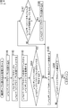
Images


Classifications
-
- G—PHYSICS
- G06—COMPUTING OR CALCULATING; COUNTING
- G06F—ELECTRIC DIGITAL DATA PROCESSING
- G06F9/00—Arrangements for program control, e.g. control units
- G06F9/06—Arrangements for program control, e.g. control units using stored programs, i.e. using an internal store of processing equipment to receive or retain programs
- G06F9/44—Arrangements for executing specific programs
- G06F9/4401—Bootstrapping
- G06F9/4418—Suspend and resume; Hibernate and awake
-
- G—PHYSICS
- G06—COMPUTING OR CALCULATING; COUNTING
- G06F—ELECTRIC DIGITAL DATA PROCESSING
- G06F9/00—Arrangements for program control, e.g. control units
- G06F9/06—Arrangements for program control, e.g. control units using stored programs, i.e. using an internal store of processing equipment to receive or retain programs
- G06F9/44—Arrangements for executing specific programs
- G06F9/445—Program loading or initiating
Definitions
- the present invention relates to a program, a control method, and a control device, and more particularly, to a program, a control method, and a control device that are suitable for controlling activation of software.
- Patent Document 1 describes that a CPU (central processing unit), I / O (input / output) register, and RAM (Random access memory) image after startup are stored in a hard disk drive (HDD) or flash memory. Has been. It is described that the stored RAM image is restored at the next startup, and then the CPU and I / O registers are reset. Patent Document 1 proposes to speed up the startup of the OS by starting up in this way. A technique called hibernation based on such a proposal has already been applied to personal computers.
- HDD hard disk drive
- the hibernation technique is also applied to embedded computers, for example, computers incorporated in electronic devices such as television receivers and hard disk recorders.
- the OS When comparing the case where the OS is activated by applying hibernation and the case where the OS is activated normally, the OS can be activated more quickly by applying hibernation.
- the RAM capacity increases, the size of the RAM image to be stored also increases, and the development time of the RAM image also increases at startup. As a result, high-speed startup becomes difficult as the capacity of the RAM increases.
- Patent Document 2 proposes a method for starting execution of the OS before completing the transfer of all the hibernation images.
- this method has a problem in that special hardware is installed and a page to be transferred in advance needs to be specified in advance, so that the cost is increased by the amount of the special hardware.
- the present invention has been made in view of such a situation, and makes it possible to shorten the startup time.
- a program according to an aspect of the present invention rewrites a page table entry in a control device having a function of managing a memory so that a page fault occurs in all pages with respect to pages necessary for operation of predetermined software.
- the software is activated, a page fault occurs in the page table entry, and the page in which the page fault has occurred is sequentially read.
- the page table entry can be rewritten, and the data, program code, table, page fault handler, interrupt vector, and register at the time of activation can be stored in the memory. .
- the page table entry to be rewritten can be stored in a RAM, and the sequentially read pages can be stored in a nonvolatile memory.
- a control method for a control device having a function of managing a memory having a function of managing a memory.
- a page table is configured so that a page fault occurs in all pages with respect to a page necessary for a predetermined software operation.
- a control device rewrites a page table entry in a control device having a function of managing a memory so that a page fault occurs in all pages with respect to a page necessary for a predetermined software operation.
- the rewriting means includes a page fault in the page table entry, and reading means for sequentially reading out the pages in which the page fault has occurred.
- the program, the control method, and the control device are such that a page table entry is rewritten so that a page fault occurs in all pages with respect to a page necessary for operation of predetermined software, and the software is started Sometimes a page fault occurs in a page table entry, and the pages with the page fault are read sequentially.
- the present invention is a technique for starting up software such as an OS (Operating System) or an application operating on a CPU (Central Processing Unit) equipped with a Memory Management Unit (hereinafter abbreviated as MMU) at high speed.
- OS Operating System
- CPU Central Processing Unit
- MMU Memory Management Unit
- the software that is the target of high-speed startup is started once in the usual way, and the RAM (Random Access Memory) image in that state is stored in a nonvolatile memory or the like.
- the RAM image is stored in a nonvolatile memory or the like
- the MMU table is rewritten so that a page fault occurs in all pages.
- the target software has a page fault handler. When a page fault occurs, only the page where the page fault has occurred is loaded from the nonvolatile memory.
- FIG. 1 is a diagram showing a configuration of an embodiment of an information processing apparatus to which the present invention is applied.
- the information processing apparatus to which the present invention is applied can be applied not only to a personal computer (PC) but also to an apparatus having an embedded computer.
- an apparatus including an embedded computer there are electronic devices such as a television receiver and a hard disk recorder.
- a case where the present invention is applied to a hard disk recorder will be described as an example.
- FIG. 1 is a diagram showing a configuration of a hard disk recorder as an information processing apparatus to which the present invention is applied.
- the hard disk recorder 100 shown in the figure includes a CPU 101, a RAM 102, a ROM (Read Only Memory) 103, a non-volatile memory 104, an MPEG (Moving Picture Picture Experts Group) encoding / decoding unit 105, a tuner 106, an HDD interface 107, an HDD 108, and an I / O. Unit 109 and activation mode switching unit 110.
- MMU Memory Management Unit
- This CPU 101 controls each part of hard disk recorder 100.
- This CPU 101 is equipped with a Memory Management Unit (hereinafter referred to as MMU), and has a mechanism that allows the RAM 102 to be subdivided and managed in small units (pages).
- MMU Memory Management Unit
- the description will be continued assuming that the MMU 131 is included in the CPU 101, but the MMU 131 may not be included in the CPU 101 but may be provided outside.
- an access permission / prohibition attribute can be set for each page, and a page fault exception can be generated when an access-prohibited page is accessed.
- the MMU 131 of the CPU 101 continues the description on the assumption that 4 kilobytes (hereinafter referred to as 4 KB) are managed as one page.
- the RAM 102 can be configured by SRAM (Static Random Access Memory), DRAM (Dynamic Random Access Memory), or the like.
- SRAM Static Random Access Memory
- DRAM Dynamic Random Access Memory
- the RAM 102 functions as a main storage device used by the CPU 101. If the RAM 102 has such a function, it can be used as the RAM 102.
- ROM 103 is a read-only memory such as FLASH ROM or Mask ROM.
- the ROM 103 stores an OS and application software, and any type of ROM may be used in the present invention as long as such storage can be performed.
- the non-volatile memory 104 is a memory that retains the stored contents even when the hard disk recorder 100 is turned off.
- it can be composed of a FLASH ROM, SRAM with a backup function, DRAM, or the like.
- the non-volatile memory 104 stores a memory image of software stored in the RAM 102 after software described later is started. Therefore, it is preferable that the capacity of the nonvolatile memory 104 is larger than the capacity of the RAM 102. However, when the data is reduced by data compression or the like, the capacity of the nonvolatile memory 104 may be equal to or less than the capacity of the RAM 102.
- the nonvolatile memory 104 can also be used as the HDD 108 (the HDD 108 can be used as the nonvolatile memory 108).
- the MPEG encoding / decoding unit 105 compresses and decompresses moving images.
- the moving image is supplied via the tuner 106.
- the tuner 106 selects one moving image from a plurality of programs (moving images) based on a user instruction, and supplies the selected moving image to the MPEG encoding / decoding unit 105.
- the MPEG encoding / decoding unit 105 supplies data from the tuner 106 to the HDD 108 via the HDD interface 107 and receives data from the HDD 108 via the HDD interface 107 as necessary. At that time, encoding or decoding processing is executed as necessary.
- the I / O unit 109 is provided for the CPU 101 to read the state of the activation mode switching unit 110.
- the software described below has a normal startup mode for acquiring a high-speed startup image and a high-speed startup mode as a startup mode after the high-speed startup image is acquired.
- the I / O 109 and the activation mode switching unit 110 are used for switching between these activation modes.
- the startup mode switching unit 110 can be configured with a switch.
- the startup mode switching unit 110 can be configured to be switched by a command from a boot loader or the like.
- the normal startup mode can be made unnecessary. Therefore, only the fast startup mode is implemented, and switching between the normal startup mode and the fast startup mode is unnecessary. .
- the I / O unit 109 and the startup mode switching unit 110 may be omitted.
- FIG. 2 is a diagram illustrating a model of the MMU 131 that the CPU 101 is equipped with.
- the MMU 131 shown in FIG. 2 is a model equipped with a CPU 101 of 32 bit class or higher.
- the configuration of the MMU 131, the physical address, the virtual address, the number of bits used for each table index, the number of table stages, and the like depend on the manufacturer of the CPU 101, but do not depend on the architecture of the manufacturer.
- a specific number such as 32 bits will be described as an example, but the numerical value does not indicate the limitation of the scope of application of the present invention.
- the MMU 131 implements a function corresponding to access permission or access permission in the attribute of the entry in the table indicating the final physical page, and a function capable of generating an exception process corresponding to a page fault or page fault when accessed in the case of disapproval At least.
- the MMU register 200 is a register provided in the MMU 131.
- the leading address of the level 1 descriptor table 201 is assigned to this register.
- the level 1 descriptor table 201 is a level 1 memory table placed on the memory.
- the virtual address 202 indicates 31 bits to 20 bits of a virtual address used as an index of the level 1 memory table.
- VA means Virtual Address (virtual address).
- the level 1 descriptor 203 is a descriptor composed of a pointer and an attribute indicating the head address of the level 2 descriptor table 204.
- the level 2 descriptor 206 is accessed by using 19 bits to 12 bits of the virtual address from the head address of the level 2 descriptor table 204 as an index.
- Level 2 disk descriptor 206 Start address of level 2 descriptor table 204 + Virtual address 205 (VA [19:12]) x 4
- the level 2 descriptor 206 is a descriptor composed of pointers and attributes indicating a 4 KB physical page 207.
- the physical page 207 is one page of physical memory that is finally converted from a virtual address to a physical address.
- the address within 4 KB of the physical page 207 is designated by a virtual address 208 (VA [11: 0]).
- FIG. 3 shows an example of the level 1 descriptor 203 and the level 2 descriptor 206.
- the descriptor in FIG. 3 is merely an example, and the present invention does not indicate that it depends on the specific CPU 101 or architecture shown in such an example.
- the base address 301 is a pointer that points to the start address of the next table or physical page.
- Attributes 302 to 304 are attribute bits indicating attributes such as executable / impossible, privileged mode / user mode, respectively.
- the access permission bit 305 is a bit indicating whether or not access to the physical page indicated by this descriptor is permitted. When there is an access to a physical page that is set to prohibit access with this access permission bit 305, an exception process called a page fault, that is, an interrupt process is generally executed, and such a mechanism is necessary. It is. Therefore, although it does not depend on the architecture of the CPU 101, the CPU 101 needs to be equipped with a page fault or a function corresponding to the page fault.
- FIG. 4 schematically shows a state in which the physical pages 207 are arranged on the RAM 102 (FIG. 1).
- the RAM 102 In the RAM 102, one page of physical pages 207 is arranged in order from the physical page 207-0 to the physical pages 207-n.
- one physical page 207 is often configured to be managed as one page in units of 4 KB to 64 KB in this way.
- FIG. 5 is a diagram for explaining a usage state of a physical page when the software is in a predetermined operation state.
- pages in which numbers are described are used pages, and pages in which numbers are not described indicate pages that are not used.
- the program code and data used by the software may be used as shown in FIG. 5 when the software state is viewed in a certain unit time even if all areas are used. Many. That is, there are pages that are used and pages that are not used, and not all pages are used.
- the recovery operation starts after the sequential reading from the physical page 207-0 to the physical page 207-n is performed. It is set to the operating state.
- the software in order for the software to be in a predetermined operation state, it is only necessary to read a plurality of predetermined physical pages 207 as shown in FIG. Therefore, in the present invention, by controlling reading as described later, only the required physical page 207 is read as shown in FIG.
- FIG. 6 is a diagram showing a physical memory map of software. Note that the processing described below depends on the CPU 101 and the OS, and as long as these functions are implemented, there is no limitation on the configuration and memory arrangement, and the present invention is applied only to the following description. It is not shown.
- the nonvolatile memory 104 is a memory that retains stored contents even when the power is turned off.
- a FLASH ROM is imagined as the nonvolatile memory 104.
- the nonvolatile memory 104 is mapped on the main memory, but the contents are retained even when the power is turned off, and the nonvolatile memory 104 has a capacity larger than that of the RAM 102.
- the nonvolatile memory 104 to which the present invention can be applied does not necessarily have to be mapped on a memory map, such as access via I / O, and there is no limitation on its architecture.
- Data 401 is a readable / writable data area used by the program code 402.
- the data 401 is stored as a physical page 207 divided into a specific size. Since the data 401 needs to be readable and writable, it is preferably placed on the RAM 102.
- the program code 402 indicates a desired program to be activated / executed.
- an OS such as Windows (registered trademark) or Linux
- the program includes the OS and the software.
- the program code 402 is divided as a physical page 207 and stored. This program code 402 is placed on the RAM 102 or the ROM 103.
- the MMU table 403 indicates the level 1 descriptor table 201 and the level 2 descriptor table 204 shown in FIG.
- the page fault handler 404 is an access-prohibited attribute of the level 2 descriptor 206 of the MMU 131, and is a program for performing exception processing via an interrupt vector when a page fault occurs.
- the page fault handler 404 is described separately from the program code 402, but it may be included in the program code 402.
- the interrupt vector 405 is an interrupt vector possessed by a general CPU.
- the program code jumps to the page fault in this interrupt vector, and as a result, the page fault handler 404 is called.
- the physical addresses for the logical addresses of the data 401, the program code 402, the MMU table 403, and the interrupt vector 405 can be mapped to arbitrary addresses.
- the image storage program 406 is a program for storing a memory image in the nonvolatile memory 104 in a desired state after a desired program is started.
- the logical address and physical address of the image storage program 406 need to be mapped to the same address.
- the image restoration program 407 reads the physical memory image saved by the processing of the image saving program 406 in units of physical pages as necessary, and reads the data 401 and the program code 402 from the nonvolatile memory 104 into the corresponding physical page. It is a program for returning.
- the logical address and physical address of the image restoration program 407 need to be mapped to the same address.
- the boot loader 408 is a boot loader that is activated first after power-on or reset.
- the boot loader 408 mainly initializes the minimum I / O necessary for starting.
- the software has such a configuration.
- the software includes an OS and the like.
- predetermined software is operated on hardware including a RAM having a capacity of 4 GB. It is assumed that the total capacity of the predetermined software program and data is 4 GB.
- the software has various modes and functions, and it is very unlikely that the full capacity of 4 GB is used only by a predetermined single function.
- the software waits for key input from the user in a specific state after startup.
- the boot loader is activated, and this software is started up and waits for a key input from the user.
- this software is activated at high speed by applying hibernation, which is a known technology, the CPU and I / O registers are stored in a state waiting for key input from the user in preparation for creating a memory image.
- a total of 4 GB of code and data is stored in some nonvolatile memory.
- the reverse is true, the normal startup process does not pass, the 4 GB memory is expanded, the CPU and I / O registers are restored, and the process returns to the key input process.
- (A) The OS or desired software is activated in the normal activation mode, and the software is in a desired state.
- the image storage program is activated, and all page tables of the MMU 131 are activated by the activated image storage program. After the predetermined information is rewritten to the information indicating the access prohibition, the memory image in the state (A) is stored in the register and the process is terminated.
- (C) After the next time , It is started in the desired state of (A) by entering the fast startup mode
- MMU 131 Memory Management Unit of the CPU is used in the present embodiment.
- the OS may use the MMU 131, but before the OS uses, the software to which the present invention is applied is restored, and the OS knows that the software to which the present invention is applied has operated the MMU 131. do not do.
- the software to which the present invention is applied also has a function of giving a mark indicating that access to the page is prohibited.
- a page fault handler 404 for processing a page fault calculates a page from the address where the page fault occurs, and the software to which the present invention is applied checks the marked mark, and the page is read from the nonvolatile memory 104 to the main memory. (For example, the RAM 102), and the MMU 131 table is written back as it was before rewriting.
- A Normal startup
- the startup mode switching unit 110 is set to the normal startup mode, and the OS and a desired program are started by a normal method.
- A-2 After a desired program is started, the software is operated to bring the software into a desired state. It is started in this state at high speed startup.
- (B) Saving state (B-1)
- the image saving program 406 is activated by any key or command. There are no particular restrictions on the activation method for this activation.
- (B-2) The image storage program 406 stores the memory image and the register in a state where it is desired to start at high speed from the next time. Specifically, the image storage program 406 sets all the tables of the MMU 131 to the access prohibited state, and the data 401, the program code 402, the MMU table 403, the page fault handler 404, the interrupt vector 405, and the register at that time Are stored in the nonvolatile memory 104.
- C Fast startup
- the startup mode switching unit 110 is set to the fast startup mode.
- the boot loader 408 determines the start mode, and when it is in the high speed start mode, calls the image restoration program 407.
- the image restoration program 407 restores the MMU table 403, page fault handler 404, and interrupt vector 405 saved by the image saving program 406.
- C-2 Return to the address after the image storage program 406 is activated in the process of B-1, that is, jump. Since all the MMUs 131 are set to the access prohibited state, a page fault occurs at the corresponding address each time the program code 402 or data 401 is accessed, and the page fault handler 404 is called.
- the page fault handler 404 reads one page of the corresponding physical page 207 from the nonvolatile memory 104 and restores the MMU 131 to its original state.
- C-4 Necessary page faults continue to occur until page faults occur one after another and the state becomes A-2.
- C-5) The physical page 207 is read until the state A-2 is reached.
- the physical page 207 read in this process depends on the software to be executed and its state, but is very small. Compared to reading all the physical pages 207 as in the conventional hibernation technique. Thus, the startup time can be significantly shortened.
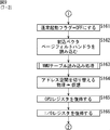
- step S101 the hard disk recorder 100 (FIG. 1) is powered on or reset to start the system.
- step S102 the boot loader 408 (FIG. 6) is activated.
- the boot loader 408 activated in step S102 initializes the minimum hardware for operating the OS and desired software, and transfers software stored in the ROM 103 and HDD 108 to the RAM 102 as necessary. Any boot loader that can execute such processing is assumed.
- the boot loader 408 depends on the system and is not essential. Therefore, depending on the system, step S102 may be omitted.
- step S103 the state of the start mode switching unit 110 is checked, and the transition between the normal start mode and the high speed start mode is switched (it is determined whether or not the normal start switch is ON).
- step S104 the process proceeds to step S161 (FIG. 9).
- step S103 If it is determined in step S103 that the normal activation switch is ON, the normal activation flag is set to ON in order to activate in the normal activation mode.
- the process proceeds to step S105, and the OS is activated if the system is equipped with the OS.
- the MMU 131 In the case of a general system, the MMU 131 is initialized when the OS is started, and the table of the MMU 131 in FIG. 2 is created. In the present invention, the installation of the OS is not essential, but the MMU 131 needs to be initialized if the system does not include the OS. Further, even if the OS is installed, there is no limitation on the type of OS.
- step S106 desired software to be started at high speed is started.
- step S107 the activated software operates.
- This process corresponds to the process A-2 described above.
- the software transitions to the same state that was started by fast startup. For example, assuming that there are a plurality of modes in the desired software, and if it is desired to start at a high speed in a specific mode, the software is operated and the mode is changed to that mode. For example, in the case of the hard disk recorder 100, there are a reservation mode, a playback mode, a setting mode, and the like, but when the user frequently uses the playback mode, the mode is changed to the playback mode.
- step S108 it is determined whether or not the processing of the image storage program 406 (FIG. 6) has been started.
- This process corresponds to the above-described process B-1. Processing by the image storage program 406 is started by a command, key operation, switch, or the like. There is no limitation on the execution means of the image storage program 406. If it is determined in step S108 that the processing of the image storage program 406 (FIG. 6) has not been started, the processing is returned to step S107, and the subsequent processing is repeated. That is, in this case, the software operation is continued.
- step S107 if it is determined in step S107 that the processing of the image storage program 406 (FIG. 6) has started, in other words, if it is determined that the operation of the software has ended, the processing proceeds to step S109.
- the following processes in steps S109 to S116 correspond to the above-described process B-2. Further, the processes in steps S109 to S116 are processes executed by the image storage program 406.
- step S109 the register of the I / O unit 109 shown in FIG. 1 is saved. Basically, the set value is acquired and saved. With respect to I / O, it is not always possible to read all registers, and in this case, it is necessary to deal with them individually. Note that the type and specification of I / O are arbitrary, and there are no particular restrictions on the application of the present invention.
- step S110 the CPU 101 register is saved. Basically, all registers of the CPU 101 are saved.
- the types of the CPU 101 and the register are arbitrary, and there are no particular restrictions on the application of the present invention.
- step S111 the address space is switched.
- the CPU 101 normally operates in the virtual address mode. This mode is changed from the virtual address mode to the physical address mode. Since the transition method from the virtual address mode to the physical address mode depends on the architecture of the MMU 131, the transition method for applying the present invention is not limited. Further, when the transition is made from the virtual address mode to the physical address mode, the address space changes. Therefore, in the processing in step S111, it is necessary to map the logical address and the physical address to the same address space.
- step S112 a cache flush is executed.
- TLB Translation Look-aside Buffer
- a primary cache a primary cache
- a secondary cache a secondary cache
- the cache flush process in step S112 is performed as necessary, and may be omitted in some cases.
- step S113 the MMU table 403 of the MMU 131 is rewritten with information that prohibits access to all physical pages 207.
- the MMU table rewriting process in step S113 will be described later with reference to the flowchart of FIG.
- step S113 when the MMU table 403 of the MMU 131 is rewritten, the process proceeds to step S114.
- step S114 a cache flush is executed. If the CPU 101 is equipped with a TLB, primary cache, and secondary cache and they are valid, the TLB and cache need to be flushed. This is to ensure that the contents of the MMU table 403 of the MMU 131 rewritten by the processing in the previous step S113 are reflected in the RAM 102.
- the cache flush process in step S114 is performed as necessary, and may be omitted in some cases.
- step S115 the entire contents of the RAM 102 are stored in the nonvolatile memory 104.
- the relative address position of the nonvolatile memory 104 with respect to the address of the RAM 102 needs to match. For example, it is assumed that the physical address of the RAM 102 is mapped from 0x10000000 to 0x1ffffff. In this case, for example, for the non-volatile memory 104, it is necessary to read data with addresses from 0x40000000 to 0x4ffffffff.
- the offset of the nonvolatile memory 104 with respect to the address of the RAM 102 is 0x30000000, even the address with respect to the RAM 102 can be converted into the address in the nonvolatile memory 104 only by adding the offset of 0x30000000.
- the nonvolatile memory 104 does not necessarily need to be mapped on the memory map. It suffices if reading can be performed using the address to which the offset is added as a key.
- the storage method for the nonvolatile memory 104 depends on the architecture, but the storage method is not limited in applying the present invention.
- step S116 the processing in the image storage program 406 is terminated.
- the power can be turned off or reset (RESET).
- step S113 there remains a detailed description of the processing when it is determined in step S103 that the normal activation switch is not ON and the MMU table rewriting processing in step S113.
- the MMU table rewriting process in step S113 will be described in detail with reference to the flowchart of FIG.
- the process based on the flowchart shown in FIG. 8 is a process in which the MMU table 403 of the MMU 131 has the configuration shown in FIG.
- step S131 when rewriting of the MMU table 403 of the MMU 131 is started, first, the head address of the level 1 descriptor table 201 is assigned to the variable level 1 descriptor pointer. In step S132, the level 1 descriptor 203 is acquired from the address pointed to by the variable level 1 descriptor pointer.
- step S133 it is determined whether or not a pointer to the level 2 descriptor table 204 exists in the level 1 descriptor 203 acquired in the process of step S132. If it is determined in step S133 that a pointer to the level 2 descriptor table 204 exists in the level 1 descriptor 203, the process proceeds to step S136, and a pointer to the level 2 descriptor table 204 exists in the level 1 descriptor 203. If it is determined not to proceed, the process proceeds to step S134.
- step S134 the variable level 1 descriptor pointer is moved to the address of the next level 1 descriptor pointer. Then, the process proceeds to step S135 to determine whether or not the level 1 descriptor pointer has finally reached.
- step S135 Until it is determined in step S135 that the level 1 descriptor pointer has finally reached, the process is returned to step S134, and the process in which the variable level 1 descriptor pointer is moved to the address of the next level 1 descriptor pointer is repeated. . If it is determined in step S135 that the level 1 descriptor pointer has finally reached, the process proceeds to step S114 (FIG. 7). That is, it is determined that the rewriting of the MMU table has been completed, and the processing is returned to the processing of the flowchart shown in FIG.
- step S133 if it is determined in step S133 that a pointer to the level 2 descriptor table 204 exists in the level 1 descriptor 203, the process proceeds to step S136.
- step S136 the head address of the level 2 descriptor table 204 is substituted for the variable level 2 descriptor pointer.
- step 137 the level 2 descriptor 206 is acquired from the address indicated by the variable level 2 descriptor pointer.
- step S138 it is determined whether or not the physical page 207 exists in the level 2 descriptor 206 acquired in the process of step S137. If it is determined in step S138 that the physical page 207 exists in the acquired level 2 descriptor 206, the process proceeds to step S139, and it is determined that there is no physical page 207 in the acquired level 2 descriptor 206. If YES, the process proceeds to step S143.
- step S139 it is determined whether or not the physical page 207 in the level 2 descriptor 206 acquired in step S137 is within the address range in the RAM 102 to be saved in step S115 (FIG. 7). Is done. If it is determined in step S139 that the physical page 207 in the level 2 descriptor 206 is within the address range in the RAM 102 to be stored, the process proceeds to step S140, and the process is advanced to the storage target RAM 102. If it is determined that it is not within the address range, the process proceeds to step S143.
- step S140 the access permission bit (access permission bit 305 in FIG. 3) of the level 2 descriptor 206 acquired in step S137 is checked to determine whether or not the physical page 207 is permitted to access. If it is determined in step S140 that access to the physical page 207 is permitted, the process proceeds to step S141. If it is determined that access to the physical page 207 is not permitted, the process proceeds to step S143. Is advanced.
- step S141 the access permission bit 305 of the level 2 descriptor 206 acquired in the process of step S137 is rewritten to a bit indicating access prohibition.
- step S142 marking is performed on the rewritten level 2 descriptor 206. In this process, whether the access permission bit 305 of the level 2 descriptor 206 acquired in the process of step S137 is rewritten by software to which the present invention is applied, or rewritten by the operation of other software, for example, the original OS or the like. This is done to store (mark) information for identifying whether the event has occurred.
- the marking method in step S142 depends on the architecture, and there is no restriction in applying the present invention. For example, if there is an empty bit that is not used in the level 2 descriptor 206, the empty bit can be used as a bit for embedding marking information. Further, a place where a table is separately provided and a place where marking is not performed may be managed. In any case, if the system is equipped with an OS or the like and the OS uses these bits, the present invention can be implemented by adopting a coexistence mechanism.
- step S143 the variable level 2 descriptor pointer is moved to the address of the pointer of the next level 2 descriptor 206.
- step S138 when it is determined in step S138 that the physical page 207 does not exist in the level 2 descriptor 206, or when it is determined in step S139 that the level 2 descriptor 206 does not point to the RAM 102. Alternatively, it comes when it is determined in step S140 that access to the physical page 207 is not permitted.
- step S144 it is determined whether or not the level 2 descriptor pointer has finally reached.
- step S144 the process returns to step S137 until it is determined that the level 2 descriptor pointer has finally reached, and the subsequent processes are repeated. On the other hand, if it is determined in step S144 that the level 2 descriptor pointer has finally reached, the process proceeds to step S134. Since the processing after step S134 has already been described, the description thereof is omitted.
- the fast startup is executed when it is determined in step S103 that the normal startup switch is not turned on, that is, when it is determined that the switch has been switched to the fast startup.
- the flowchart of FIG. 9 is a flowchart in which the process proceeds when it is determined in step S103 that the normal activation switch is not turned on, and is a flowchart for explaining the process at the time of high-speed activation.
- step S161 the normal start flag is set to OFF (the fast start flag is ON) in order to start in the high speed start mode.
- step S162 as necessary, the interrupt vector 405, the page fault handler 404, and the MMU table 403 are read into the same address of the RAM 102 as when the image was saved.
- step S163 the MMU table of the MMU 131 is read.
- the MMU table reading process executed in step S163 will be described later with reference to the flowchart of FIG.
- step S164 the address space of the CPU 101 is changed from the physical address mode to the virtual address mode.
- the address space changes. Therefore, in the processing in step S164, the logical address and the physical address are mapped to the same address space.
- step S165 the value of the register of the CPU 101 saved in step S110 (FIG. 7) is read from the nonvolatile memory 104 and returned to the CPU 101.
- the type of the CPU 101 and the register is arbitrary, and there is no limitation in applying the present invention.
- step S166 the I / O register value saved in step S109 (FIG. 7) is read from the nonvolatile memory 104 and returned to the I / O unit 109.
- the type and specification of I / O are arbitrary, and there are no restrictions on the application of the present invention.
- step S107 the software operates.
- the processing of steps S104 to S106 is not executed, and the software starts operation in step S107. Therefore, at least the time required for the software to start operating can be shortened by the amount of processing in steps S104 to S106.
- the time required for starting the OS and initializing the MMU in step S105 and the time required for starting the software in step S106 can be eliminated, a significant reduction in time can be expected.
- step S181 when reading of the MMU table 403 is started, the level 1 descriptor table 201 is first read.
- the contents of the RAM 102 are stored in the nonvolatile memory 104 in the process of step S115 (FIG. 7). From the contents stored in the nonvolatile memory 104, only the level 1 descriptor table 201 is stored. Read out.
- step S182 the leading address of the level 1 descriptor table 201 is assigned to the variable level 1 descriptor pointer.
- step S183 the level 1 descriptor 203 is acquired from the address indicated by the variable level 1 descriptor pointer.
- step S184 it is determined whether or not a pointer to the level 2 descriptor table 204 exists in the level 1 descriptor 203 acquired in the process of step S183.
- step 184 If it is determined in step 184 that a pointer to the level 2 descriptor table 204 exists in the acquired level 1 descriptor 203, the process proceeds to step S187, and the level 2 descriptor table is stored in the acquired level 1 descriptor 203. If it is determined that there is no pointer to 204, the process proceeds to step S185.
- step S185 the variable level 1 descriptor pointer is moved to the address of the next level 1 descriptor pointer. Then, in step S186, it is determined whether or not the level 1 descriptor pointer has finally reached. If it is determined in step S186 that the level 1 descriptor pointer has reached the end, the process proceeds to step S164 (FIG. 9). That is, in this case, since the reading of the MMU table 403 is completed, the process proceeds to the next process.
- step S186 determines whether the level 1 descriptor pointer 203 has been reached the final value. If it is determined in step S186 that the level 1 descriptor pointer 203 has not reached the final value, the processing is returned to step S183, and the subsequent processing is repeated. Steps S183 to S186 are repeated, and if it is determined in step S184 that a pointer to the level 2 descriptor table 204 exists in the acquired level 1 descriptor 203, the process proceeds to step S187.
- step S187 it is determined whether or not the pointer to the level 2 descriptor table 204 in the level 1 descriptor 203 acquired in step S183 points to the RAM 102. If it is determined in step S187 that the pointer to the level 2 descriptor table 204 points to the RAM 102, the process proceeds to step S188, and it is determined that the pointer to the level 2 descriptor table 204 does not point to the RAM 102. If so, the process proceeds to step S185, and the subsequent processes are repeated.
- step S188 the level 2 descriptor table is read.
- the level 2 descriptor table 204 is stored as the contents of the RAM 102 in the nonvolatile memory 104 in the process of step S115 (FIG. 7), and only the level 2 descriptor table 204 is read from the contents stored in the nonvolatile memory 104. . Thereafter, the process proceeds to step S185, and the subsequent processes are repeated.
- step S201 the process jumps to the interrupt vector 405. That is, a jump from the interrupt vector 405 to the interrupt handler that performs the actual page fault process is executed.
- the general CPU 101 jumps to a specific interrupt vector as an interrupt process and processes it as an interrupt handler.
- the flowchart relating to the processing when a page fault occurs shown in FIG. 11 assumes an interrupt handler that processes a page fault interrupt, but these depend on the architecture of the CPU 101.
- the application of the present invention is not limited by the manufacturer or model number of the CPU 101.
- step S202 it is determined whether or not the normal activation flag is ON.
- the normal activation flag is set to ON in the process of step S104 (FIG. 7).
- step S202 if it is determined that the normal activation flag is ON, in other words, if it is determined that the normal activation flag is normal, the process proceeds to step S207.
- step S203 if it is determined in step S202 that the normal activation flag is not ON, in other words, if it is determined that high-speed activation is performed, the process proceeds to step S203.
- step S203 it is determined whether the target physical page 207, that is, the physical page 207 corresponding to the address where the page fault has occurred is the marked physical page 207.
- the marking is a marking executed in the process of step S142 (FIG. 8). That is, the marked physical page 207 is a physical page 207 that has been rewritten to prohibit access by software to which the present invention is applied.
- Physical page address / page size (for example, 4KB in the above example) As shown in this equation, the physical page is obtained by dividing the address by the page size.
- step S203 if it is determined that the physical page 207 corresponding to the address where the page fault has occurred is a marked physical page 207, the process proceeds to step S204, and the physical page 207 is not marked. If it is determined, the process proceeds to step S207.
- step S204 the target physical page 207, that is, the physical page 207 corresponding to the address where the page fault has occurred is read out by 4 KB from the image stored in the nonvolatile memory 104 in the process of step S115 (FIG. 7).
- step S205 the access permission bit 305 of the level 2 descriptor 206 of the target physical page 207, that is, the physical page 207 corresponding to the address where the page fault has occurred is rewritten to access permission.
- step S206 the identification information marked in step S142 (FIG. 8) is canceled.
- step S207 standard page fault processing is executed. That is, during normal startup, or when software (such as an OS) other than the software to which the present invention is applied has been set to disallow access, normal startup or access disapproval processing is executed.
- step S207 depends on the system such as the OS and is not an essential process, and can be omitted in the present embodiment.
- Digital home appliances such as television receivers and hard disk recorders include models equipped with an OS (predetermined software).
- OS predetermined software
- the startup time may be long, but by applying the present invention, the startup time in these digital home appliances can be shortened.
- the battery life can be extended.
- a conventional method for realizing high-speed startup there has been a method of shifting a CPU or a memory to a power saving mode. In this method, although it is a power saving mode, power is required, and power consumption cannot be ignored for a battery-powered device.
- the present invention it is possible to save a startup image in a nonvolatile memory, and it is not necessary to use so-called suspend (corresponding to a conventional power saving mode) in which power is stopped while being supplied to a RAM. As a result, the battery life can be significantly extended.
- the start-up time can be shortened by applying the present invention, the start-up time can be started with a start time shorter than or equal to the start-up time required in the “fast start-up mode”. Therefore, it is not necessary to provide a “fast start-up mode”. Accordingly, it is possible to eliminate the state where the power must be constantly turned on in the “fast start-up mode”, and as a result, energy saving can be realized.
- the program executed by the computer described above may be a program that is processed in time series in the order described in this specification, or in parallel or at a necessary timing such as when a call is made. It may be a program for processing. It can also be configured with dedicated hardware. Further, in this specification, the system represents the entire apparatus constituted by a plurality of apparatuses.
Landscapes
- Engineering & Computer Science (AREA)
- Software Systems (AREA)
- Theoretical Computer Science (AREA)
- Computer Security & Cryptography (AREA)
- Physics & Mathematics (AREA)
- General Engineering & Computer Science (AREA)
- General Physics & Mathematics (AREA)
- Stored Programmes (AREA)
- Memory System Of A Hierarchy Structure (AREA)
Priority Applications (3)
| Application Number | Priority Date | Filing Date | Title |
|---|---|---|---|
| US13/375,659 US20120072658A1 (en) | 2009-06-02 | 2010-03-05 | Program, control method, and control device |
| EP10783189A EP2439639A4 (en) | 2009-06-02 | 2010-03-05 | PROGRAM, CONTROL PROCEDURE AND CONTROL DEVICE |
| CN2010800246514A CN102460384A (zh) | 2009-06-02 | 2010-03-05 | 程序、控制方法以及控制装置 |
Applications Claiming Priority (2)
| Application Number | Priority Date | Filing Date | Title |
|---|---|---|---|
| JP2009-132708 | 2009-06-02 | ||
| JP2009132708A JP4986247B2 (ja) | 2009-06-02 | 2009-06-02 | プログラム、制御方法、並びに制御装置 |
Publications (1)
| Publication Number | Publication Date |
|---|---|
| WO2010140403A1 true WO2010140403A1 (ja) | 2010-12-09 |
Family
ID=43297544
Family Applications (1)
| Application Number | Title | Priority Date | Filing Date |
|---|---|---|---|
| PCT/JP2010/053627 Ceased WO2010140403A1 (ja) | 2009-06-02 | 2010-03-05 | プログラム、制御方法、並びに制御装置 |
Country Status (5)
| Country | Link |
|---|---|
| US (1) | US20120072658A1 (enExample) |
| EP (1) | EP2439639A4 (enExample) |
| JP (1) | JP4986247B2 (enExample) |
| CN (1) | CN102460384A (enExample) |
| WO (1) | WO2010140403A1 (enExample) |
Cited By (2)
| Publication number | Priority date | Publication date | Assignee | Title |
|---|---|---|---|---|
| WO2012104950A1 (ja) * | 2011-01-31 | 2012-08-09 | パナソニック株式会社 | 起動制御装置、情報機器および起動制御方法 |
| CN102662690A (zh) * | 2012-03-14 | 2012-09-12 | 腾讯科技(深圳)有限公司 | 应用程序启动方法和装置 |
Families Citing this family (30)
| Publication number | Priority date | Publication date | Assignee | Title |
|---|---|---|---|---|
| CN103914318A (zh) * | 2013-01-04 | 2014-07-09 | 腾讯科技(深圳)有限公司 | 程序启动的方法和装置 |
| JP5901698B2 (ja) | 2014-06-17 | 2016-04-13 | インターナショナル・ビジネス・マシーンズ・コーポレーションInternational Business Machines Corporation | メモリ管理方法 |
| US9830289B2 (en) | 2014-09-16 | 2017-11-28 | Apple Inc. | Methods and apparatus for aggregating packet transfer over a virtual bus interface |
| US9971397B2 (en) | 2014-10-08 | 2018-05-15 | Apple Inc. | Methods and apparatus for managing power with an inter-processor communication link between independently operable processors |
| US10042794B2 (en) | 2015-06-12 | 2018-08-07 | Apple Inc. | Methods and apparatus for synchronizing uplink and downlink transactions on an inter-device communication link |
| EP3153971B1 (en) * | 2015-10-08 | 2018-05-23 | Huawei Technologies Co., Ltd. | A data processing apparatus and a method of operating a data processing apparatus |
| US10085214B2 (en) | 2016-01-27 | 2018-09-25 | Apple Inc. | Apparatus and methods for wake-limiting with an inter-device communication link |
| US10191852B2 (en) | 2016-02-29 | 2019-01-29 | Apple Inc. | Methods and apparatus for locking at least a portion of a shared memory resource |
| US10198364B2 (en) | 2016-03-31 | 2019-02-05 | Apple Inc. | Memory access protection apparatus and methods for memory mapped access between independently operable processors |
| US10775871B2 (en) | 2016-11-10 | 2020-09-15 | Apple Inc. | Methods and apparatus for providing individualized power control for peripheral sub-systems |
| US10551902B2 (en) | 2016-11-10 | 2020-02-04 | Apple Inc. | Methods and apparatus for providing access to peripheral sub-system registers |
| US10346226B2 (en) | 2017-08-07 | 2019-07-09 | Time Warner Cable Enterprises Llc | Methods and apparatus for transmitting time sensitive data over a tunneled bus interface |
| US10331612B1 (en) | 2018-01-09 | 2019-06-25 | Apple Inc. | Methods and apparatus for reduced-latency data transmission with an inter-processor communication link between independently operable processors |
| CN108564981B (zh) * | 2018-03-27 | 2021-10-01 | 深圳忆联信息系统有限公司 | 一种存储装置数据安全动态监控方法 |
| US11792307B2 (en) | 2018-03-28 | 2023-10-17 | Apple Inc. | Methods and apparatus for single entity buffer pool management |
| US10430352B1 (en) | 2018-05-18 | 2019-10-01 | Apple Inc. | Methods and apparatus for reduced overhead data transfer with a shared ring buffer |
| US10585699B2 (en) | 2018-07-30 | 2020-03-10 | Apple Inc. | Methods and apparatus for verifying completion of groups of data transactions between processors |
| US10846224B2 (en) | 2018-08-24 | 2020-11-24 | Apple Inc. | Methods and apparatus for control of a jointly shared memory-mapped region |
| US10719376B2 (en) | 2018-08-24 | 2020-07-21 | Apple Inc. | Methods and apparatus for multiplexing data flows via a single data structure |
| US10789110B2 (en) | 2018-09-28 | 2020-09-29 | Apple Inc. | Methods and apparatus for correcting out-of-order data transactions between processors |
| US10838450B2 (en) | 2018-09-28 | 2020-11-17 | Apple Inc. | Methods and apparatus for synchronization of time between independently operable processors |
| US11558348B2 (en) | 2019-09-26 | 2023-01-17 | Apple Inc. | Methods and apparatus for emerging use case support in user space networking |
| US11829303B2 (en) | 2019-09-26 | 2023-11-28 | Apple Inc. | Methods and apparatus for device driver operation in non-kernel space |
| US11513970B2 (en) * | 2019-11-01 | 2022-11-29 | International Business Machines Corporation | Split virtual memory address loading mechanism |
| US11606302B2 (en) | 2020-06-12 | 2023-03-14 | Apple Inc. | Methods and apparatus for flow-based batching and processing |
| US11775359B2 (en) | 2020-09-11 | 2023-10-03 | Apple Inc. | Methods and apparatuses for cross-layer processing |
| US11954540B2 (en) | 2020-09-14 | 2024-04-09 | Apple Inc. | Methods and apparatus for thread-level execution in non-kernel space |
| US11799986B2 (en) | 2020-09-22 | 2023-10-24 | Apple Inc. | Methods and apparatus for thread level execution in non-kernel space |
| US11876719B2 (en) | 2021-07-26 | 2024-01-16 | Apple Inc. | Systems and methods for managing transmission control protocol (TCP) acknowledgements |
| US11882051B2 (en) | 2021-07-26 | 2024-01-23 | Apple Inc. | Systems and methods for managing transmission control protocol (TCP) acknowledgements |
Citations (3)
| Publication number | Priority date | Publication date | Assignee | Title |
|---|---|---|---|---|
| JP2005149225A (ja) | 2003-11-17 | 2005-06-09 | Sony Corp | コンピュータシステム及びその起動方法 |
| JP2006202252A (ja) * | 2004-12-24 | 2006-08-03 | Canon Inc | 電子機器、データ処理方法、及びコンピュータプログラム |
| JP2007334383A (ja) | 2006-06-12 | 2007-12-27 | Sony Corp | 情報処理装置とその起動方法およびプログラム |
Family Cites Families (9)
| Publication number | Priority date | Publication date | Assignee | Title |
|---|---|---|---|---|
| US6694451B2 (en) * | 2000-12-07 | 2004-02-17 | Hewlett-Packard Development Company, L.P. | Method for redundant suspend to RAM |
| US6546472B2 (en) * | 2000-12-29 | 2003-04-08 | Hewlett-Packard Development Company, L.P. | Fast suspend to disk |
| US6883037B2 (en) * | 2001-03-21 | 2005-04-19 | Microsoft Corporation | Fast data decoder that operates with reduced output buffer bounds checking |
| JP3906825B2 (ja) * | 2003-06-17 | 2007-04-18 | 日本電気株式会社 | 計算機システム、計算機システム起動方法およびプログラム |
| JP4604543B2 (ja) * | 2004-04-30 | 2011-01-05 | 日本電気株式会社 | 計算機、計算機起動方法、管理サーバ装置およびプログラム |
| EP1672487A1 (en) * | 2004-12-14 | 2006-06-21 | Sony Ericsson Mobile Communications AB | Method and means for an efficient memory usage |
| US8930659B2 (en) * | 2005-03-31 | 2015-01-06 | Nec Corporation | Computer system, memory management method and program thereof |
| US7620784B2 (en) * | 2006-06-09 | 2009-11-17 | Microsoft Corporation | High speed nonvolatile memory device using parallel writing among a plurality of interfaces |
| US8423740B2 (en) * | 2011-02-01 | 2013-04-16 | Wind River Systems, Inc. | System and method for fast boot from non-volatile memory |
-
2009
- 2009-06-02 JP JP2009132708A patent/JP4986247B2/ja active Active
-
2010
- 2010-03-05 CN CN2010800246514A patent/CN102460384A/zh active Pending
- 2010-03-05 WO PCT/JP2010/053627 patent/WO2010140403A1/ja not_active Ceased
- 2010-03-05 US US13/375,659 patent/US20120072658A1/en not_active Abandoned
- 2010-03-05 EP EP10783189A patent/EP2439639A4/en not_active Withdrawn
Patent Citations (3)
| Publication number | Priority date | Publication date | Assignee | Title |
|---|---|---|---|---|
| JP2005149225A (ja) | 2003-11-17 | 2005-06-09 | Sony Corp | コンピュータシステム及びその起動方法 |
| JP2006202252A (ja) * | 2004-12-24 | 2006-08-03 | Canon Inc | 電子機器、データ処理方法、及びコンピュータプログラム |
| JP2007334383A (ja) | 2006-06-12 | 2007-12-27 | Sony Corp | 情報処理装置とその起動方法およびプログラム |
Non-Patent Citations (1)
| Title |
|---|
| See also references of EP2439639A4 |
Cited By (6)
| Publication number | Priority date | Publication date | Assignee | Title |
|---|---|---|---|---|
| WO2012104950A1 (ja) * | 2011-01-31 | 2012-08-09 | パナソニック株式会社 | 起動制御装置、情報機器および起動制御方法 |
| CN103329099A (zh) * | 2011-01-31 | 2013-09-25 | 松下电器产业株式会社 | 启动控制装置、信息设备以及启动控制方法 |
| JP5870043B2 (ja) * | 2011-01-31 | 2016-02-24 | 株式会社ソシオネクスト | 起動制御装置、情報機器および起動制御方法 |
| CN103329099B (zh) * | 2011-01-31 | 2016-03-16 | 株式会社索思未来 | 启动控制装置、信息设备以及启动控制方法 |
| US9442724B2 (en) | 2011-01-31 | 2016-09-13 | Socionext Inc. | Start control apparatus for controlling a start of an information device by using an interrupt generation code, information device, and start control method |
| CN102662690A (zh) * | 2012-03-14 | 2012-09-12 | 腾讯科技(深圳)有限公司 | 应用程序启动方法和装置 |
Also Published As
| Publication number | Publication date |
|---|---|
| US20120072658A1 (en) | 2012-03-22 |
| CN102460384A (zh) | 2012-05-16 |
| JP2010282252A (ja) | 2010-12-16 |
| EP2439639A1 (en) | 2012-04-11 |
| EP2439639A4 (en) | 2013-03-06 |
| JP4986247B2 (ja) | 2012-07-25 |
Similar Documents
| Publication | Publication Date | Title |
|---|---|---|
| JP4986247B2 (ja) | プログラム、制御方法、並びに制御装置 | |
| WO2011061948A1 (ja) | プログラム、制御方法、並びに制御装置 | |
| US8949512B2 (en) | Trim token journaling | |
| CN110032403B (zh) | 存储器装置与电子装置的启动程序加载方法 | |
| US8255614B2 (en) | Information processing device that accesses memory, processor and memory management method | |
| JP5336060B2 (ja) | 不揮発性メモリ装置およびそれを動作させる方法 | |
| US7844772B2 (en) | Device driver including a flash memory file system and method thereof and a flash memory device and method thereof | |
| CN102667736B (zh) | 存储器管理装置及存储器管理方法 | |
| US8756458B2 (en) | Mount-time reconciliation of data availability | |
| EP2570927B1 (en) | Handling unclean shutdowns for a system having non-volatile memory | |
| US11301331B2 (en) | Storage device and operating method of storage device | |
| US20140304497A1 (en) | Electronic device having function of booting operating system by bootloader, method of performing the same function, and storage medium | |
| US8825946B2 (en) | Memory system and data writing method | |
| US20150074336A1 (en) | Memory system, controller and method of controlling memory system | |
| JP5506418B2 (ja) | プログラム、制御方法、並びに制御装置 | |
| CN115774681B (zh) | 信息处理装置 | |
| KR101582919B1 (ko) | 전자장치 및 그 부팅방법 | |
| WO2011061949A1 (ja) | プログラム、制御方法、並びに制御装置 | |
| US11061728B2 (en) | Systems and methods for heterogeneous address space allocation | |
| WO2009086692A1 (zh) | 嵌入式系统利用nand闪存记忆体储存及启动的处理方法 | |
| JP2007094497A (ja) | 情報処理装置及び情報処理方法 | |
| KR101881039B1 (ko) | 비휘발성 메모리에 저장된 메모리 매핑 파일의 비동기식 원자적 업데이트 방법 및 제어 장치 | |
| KR20090120298A (ko) | 비휘발성 메모리에 기반한 컴퓨터 시스템 |
Legal Events
| Date | Code | Title | Description |
|---|---|---|---|
| WWE | Wipo information: entry into national phase |
Ref document number: 201080024651.4 Country of ref document: CN |
|
| 121 | Ep: the epo has been informed by wipo that ep was designated in this application |
Ref document number: 10783189 Country of ref document: EP Kind code of ref document: A1 |
|
| WWE | Wipo information: entry into national phase |
Ref document number: 13375659 Country of ref document: US |
|
| NENP | Non-entry into the national phase |
Ref country code: DE |
|
| WWE | Wipo information: entry into national phase |
Ref document number: 2010783189 Country of ref document: EP |