WO2010137577A1 - 天井用放射パネルを使用した天井照明装置 - Google Patents
天井用放射パネルを使用した天井照明装置 Download PDFInfo
- Publication number
- WO2010137577A1 WO2010137577A1 PCT/JP2010/058795 JP2010058795W WO2010137577A1 WO 2010137577 A1 WO2010137577 A1 WO 2010137577A1 JP 2010058795 W JP2010058795 W JP 2010058795W WO 2010137577 A1 WO2010137577 A1 WO 2010137577A1
- Authority
- WO
- WIPO (PCT)
- Prior art keywords
- ceiling
- emitting diode
- radiating
- light
- panels
- Prior art date
- Legal status (The legal status is an assumption and is not a legal conclusion. Google has not performed a legal analysis and makes no representation as to the accuracy of the status listed.)
- Ceased
Links
Images




Classifications
-
- F—MECHANICAL ENGINEERING; LIGHTING; HEATING; WEAPONS; BLASTING
- F21—LIGHTING
- F21V—FUNCTIONAL FEATURES OR DETAILS OF LIGHTING DEVICES OR SYSTEMS THEREOF; STRUCTURAL COMBINATIONS OF LIGHTING DEVICES WITH OTHER ARTICLES, NOT OTHERWISE PROVIDED FOR
- F21V33/00—Structural combinations of lighting devices with other articles, not otherwise provided for
- F21V33/0088—Ventilating systems
- F21V33/0092—Ventilating systems with heating or cooling devices
-
- F—MECHANICAL ENGINEERING; LIGHTING; HEATING; WEAPONS; BLASTING
- F24—HEATING; RANGES; VENTILATING
- F24D—DOMESTIC- OR SPACE-HEATING SYSTEMS, e.g. CENTRAL HEATING SYSTEMS; DOMESTIC HOT-WATER SUPPLY SYSTEMS; ELEMENTS OR COMPONENTS THEREFOR
- F24D3/00—Hot-water central heating systems
- F24D3/12—Tube and panel arrangements for ceiling, wall, or underfloor heating
- F24D3/16—Tube and panel arrangements for ceiling, wall, or underfloor heating mounted on, or adjacent to, a ceiling, wall or floor
- F24D3/165—Suspended radiant heating ceiling
-
- F—MECHANICAL ENGINEERING; LIGHTING; HEATING; WEAPONS; BLASTING
- F24—HEATING; RANGES; VENTILATING
- F24F—AIR-CONDITIONING; AIR-HUMIDIFICATION; VENTILATION; USE OF AIR CURRENTS FOR SCREENING
- F24F5/00—Air-conditioning systems or apparatus not covered by F24F1/00 or F24F3/00, e.g. using solar heat or combined with household units such as an oven or water heater
- F24F5/0089—Systems using radiation from walls or panels
- F24F5/0092—Systems using radiation from walls or panels ceilings, e.g. cool ceilings
-
- F—MECHANICAL ENGINEERING; LIGHTING; HEATING; WEAPONS; BLASTING
- F24—HEATING; RANGES; VENTILATING
- F24F—AIR-CONDITIONING; AIR-HUMIDIFICATION; VENTILATION; USE OF AIR CURRENTS FOR SCREENING
- F24F2221/00—Details or features not otherwise provided for
- F24F2221/02—Details or features not otherwise provided for combined with lighting fixtures
-
- Y—GENERAL TAGGING OF NEW TECHNOLOGICAL DEVELOPMENTS; GENERAL TAGGING OF CROSS-SECTIONAL TECHNOLOGIES SPANNING OVER SEVERAL SECTIONS OF THE IPC; TECHNICAL SUBJECTS COVERED BY FORMER USPC CROSS-REFERENCE ART COLLECTIONS [XRACs] AND DIGESTS
- Y02—TECHNOLOGIES OR APPLICATIONS FOR MITIGATION OR ADAPTATION AGAINST CLIMATE CHANGE
- Y02B—CLIMATE CHANGE MITIGATION TECHNOLOGIES RELATED TO BUILDINGS, e.g. HOUSING, HOUSE APPLIANCES OR RELATED END-USER APPLICATIONS
- Y02B30/00—Energy efficient heating, ventilation or air conditioning [HVAC]
Definitions
- the present invention relates to a ceiling lighting device using a radiant panel installed on the ceiling in order to perform air conditioning in a room such as an office room, a lobby or a hall.
- the ceiling in the room is made of a flat plate with a good heat conductive material such as aluminum.
- a plurality of radiating panels are arranged side by side, and each radiating panel is cooled or heated by a heat medium flowing in an air conditioning pipe provided on the upper surface thereof.
- Patent Document 4 a plurality of light emitting diodes (LEDs) are used, and the plurality of light emitting diodes are indirectly cooled with water, thereby improving the light emission efficiency and extending the lifetime.
- An illuminating device having a configuration for achieving the above is disclosed.
- the light emitting diode in the lighting device requires cooling to improve the light emission efficiency and extend the life even when the cooling and heating by the radiating panel is not performed, only this amount is required.
- the equipment cost is greatly increased because fins for cooling or cooling water piping are required as cooling means for the light emitting diode.
- Patent Document 4 a separate cooling water pipe is required to cool the light emitting diode (LED), and in Patent Documents 1 to 3, a separate cooling water pipe is required in addition to the cooling / heating pipe. This increases the equipment cost significantly.
- the present invention when installing a light emitting diode on a radiant panel installed on the ceiling for ceiling lighting, uses the radiant panel to improve the light emission efficiency of the light emitting diode and extend its life,
- the technical problem is to make the ceiling lighting with soft light without increasing the manufacturing cost of the radiant panel and to reduce the equipment cost.
- claim 1 “A plurality of radiant panels arranged side by side so as to form a ceiling, an air conditioner pipe provided on the upper surface of each radiant panel through which a heat medium for air conditioner flows, and a light-emitting diode illuminator, A concave groove from the lower surface of the radiating panel is formed to extend along the joint at an arbitrary joint among the joints between the radiating panels, and the light emitting diode illumination is formed in the concave groove.
- a plurality of instruments are detachably attached at appropriate intervals along the direction in which the recessed groove extends.
- Claim 2 “In the description of claim 1, at least one of the left and right inner surfaces of the recessed groove is inclined inwardly upward.” It is characterized by that.
- the air-conditioning / heating pipe on the upper surface of the radiating panel is configured to extend along the recessed groove.” It is characterized by that.
- the recessed groove is formed between lip pieces formed by bending a portion of the radiating panel adjacent to the recessed groove upward.” It is characterized by that.
- a concave groove from the lower surface is arbitrarily provided in the joint between the radiating panels provided side by side so as to constitute the ceiling, and a plurality of light-emitting diode luminaires are provided in the groove.
- the light-emitting diode illuminating device in the recessed groove is hidden in the recessed groove, and light having strong directivity from the hidden light-emitting diode illuminating device does not directly enter the field of view. Reflecting downward on the inner surface of the recessed groove to illuminate the room, glare is alleviated and ceiling lighting with soft light can be achieved.
- the light emitting diode illuminating device transfers heat to the air conditioning / heating pipe provided on the upper surface of the light emitting diode lighting device via the radiating panel, and further to the air conditioning / heating heat medium flowing in the air conditioning / heating pipe. Since the cooling is performed so as to approach the temperature of the heating / cooling heat medium, it is possible to reliably achieve a long life and an improvement in luminous efficiency in the light-emitting diode lighting device, and to cool the light-emitting diode lighting device. The load can be reduced.
- the radiation panel functions as a heat radiation fin for the light-emitting diode illuminator attached to the radiant panel when the radiant panel is not cooled or heated, the luminous efficiency of the light-emitting diode illuminator is improved and the lifetime is increased. Therefore, the light-emitting diode illuminating device does not require a cooling means with water or the like, so that the cooling load can be reduced and the equipment can be reduced. A significant reduction in costs can be achieved.
- the heat generated in the light emitting diodes is radiated to the air in the room (residential space) or the ceiling and is agitated and absorbed by the air conditioning equipment. Invite the increase.
- the heat generated by the light emitting diode is mainly transmitted to the radiating panel, and is efficiently absorbed by the heating / cooling heat medium having a large heat capacity. Therefore, the heat radiation to the air is extremely reduced, and the air conditioning load in the room can be reduced, so that energy saving can be achieved.
- At least one of the left and right inner surfaces of the groove portion is a light reflecting surface that reflects light from the light emitting diode downward, ceiling illumination by the light emitting diode illuminator is performed. , It can be close to indirect lighting, and it can be made a softer ceiling lighting.
- heat transfer from the plurality of light emitting diode luminaires provided in the recessed groove to the air conditioning pipe can be improved. Can promote.
- FIG. 3 is an enlarged sectional view taken along line III-III in FIG.
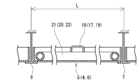
- FIG. 4 is a sectional view taken along line IV-IV in FIG. 2.
- FIG. 2 It is a perspective view which shows the part of the joint in a radiation panel. It is a figure which shows another embodiment of FIG. It is a figure which shows another embodiment of FIG.
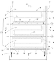
- FIG. 1 is a perspective view of the interior of the room as viewed from the back, and FIG. 2 shows the interior of the room as viewed from below.
- reference numeral 1 denotes a building or the like, and a ceiling unit 3 is provided on the ceiling in the room 2 such as an office in the building 1.
- the ceiling unit 3 includes a plurality of sets of three radiating panels each including a first radiating panel 4, a second radiating panel 5, and a third radiating panel 6. Are arranged in the vertical and horizontal directions.
- the radiating panels 4, 5 and 6 are placed on the ceiling support members 7 and 8 having a T-shape with the left and right ends in the longitudinal direction facing downward. It is configured to support.
- Each of the radiating panels 4, 5 and 6 has a rectangular shape in which the length L is approximately three times the width W, and is a thin metal plate having excellent heat transfer properties such as aluminum. Manufactured by press molding.
- the metal thin plate is a punching plate having a large number of holes, and the left and right edge portions along the longitudinal direction of the radiation panels 4, 5 and 6, that is, the radiation panels. As shown in FIGS. 3 and 5, lip pieces 4a, 4b, 5a, 5b, 6a, 6b formed by bending upward are provided at the joints between 4, 5, and 6, respectively.
- the lip pieces 4a and 6b at the joint 9 are provided at the joint 9 between the first radiation panel 4 and the third radiation panel 6 adjacent to the left side of the radiation panels 4, 5 and 6.
- Each of these is formed into an outward inverted L-shape, and the tips thereof are overlapped with each other to form a recessed groove 10 from the lower surface therebetween.
- each of the lip pieces 4b and 5a in the portion of the joint 11 is inwardly L-shaped.
- the cushion material 12 is sandwiched between them.
- each of the lip pieces 5b, 6a in the joint 13 is formed in an outward L-shape and the tip thereof is formed.
- a recessed groove 14 from the lower surface is formed therebetween.
- the joint 15 of the third radiating panel 6 and the first radiating panel 4 connected to the right side of the third radiating panel 6 has the lip pieces 6b and 4a at the joint 15 in an inward L-shape.
- the cushion material 16 is sandwiched between them.
- each of the radiating panels 4, 5, and 6 deformation preventing members 17, 18, and 19 extending in the width direction are provided between the lip pieces 4a, 4b, 5a, 5b, 6a, and 6b on both left and right edges. This ensures that each of the radiating panels 4, 5 and 6 is prevented from being warped and deformed downwardly as shown by a two-dot chain line in FIG. It is composed.
- the deformation preventing members 17, 18, and 19 are not limited to being provided at one place in the length direction of each of the radiation panels 4, 5, and 6, and are provided at a plurality of places in the length direction. Can be.
- Each of the deformation preventing members 7, 8, 9 is made of a metal having excellent heat transfer properties such as aluminum.
- cooling and heating pipes 20, 21, 22 formed in a zigzag shape are in close contact with the upper surfaces of the radiating panels 4, 5, 6.
- One end of each of these air conditioning pipes 20, 21, 22 is connected to the supply line 23, and the other end is connected to the exhaust pipe 24, and each of these air conditioning pipes 20, 21, 22, the surface of each of the radiating panels 4, 5, 6 is brought to the above-described temperature by flowing a cooling / heating heating medium such as water held at a predetermined temperature (20-30 ° C.) by a device (not shown).
- a cooling / heating heating medium such as water held at a predetermined temperature (20-30 ° C.
- the cooling and heating pipes 20, 21, 22 on the upper surfaces of the respective radiation panels 4, 5, 6 are radiated at the respective surfaces by the deformation preventing members 17, 18, 19 being in direct contact with the upper surfaces.
- a part of each of the cooling and heating pipes 20, 21, and 22 is pressed and in close contact with the upper surfaces of the panels 4, 5, and 6, as shown in FIG. 6 adjacent to the joints 9, 11, 13, 15 between the two, and thus adjacent to the recessed grooves 10, 14 in the joints 9, 13, and extending substantially parallel thereto.
- At least one light emitting diode chip is provided in the recessed grooves 10 and 14 formed in some of the joints 9, 13, 13 of the joints 9, 11, 13, 15 of the radiation panels 4, 5, 6.
- a plurality of light-emitting diode luminaires 25 are provided at appropriate intervals along the direction in which the recessed grooves 10 and 14 extend.
- Each light-emitting diode illuminating device 25 is detachably attached to the ceiling surface in the recessed grooves 10 and 14 by screws or the like (not shown), or as indicated by a two-dot chain line in FIG.
- screws or the like not shown
- a two-dot chain line in either one or both of the two lip pieces 4a and 6b constituting both the left and right inner side surfaces in the above, on either one or both of the two lip pieces 5b and 6a constituting the left and right inner side surfaces in the recessed groove 14, It is detachably attached.
- Each light-emitting diode illuminator 25 mounted in the recessed grooves 10 and 14 has a power cord (Wiring) extending in the recessed grooves 10 and 14 so as to extend in the longitudinal direction thereof. (Not shown).
- the left and right lip pieces 6b (5b) for forming the recessed grooves 10 and 14 are provided with individual wiring cords 25 'for the respective light-emitting diode luminaires 25.
- 4a (6a) a lip piece 4a (6a) on one side is pulled out from a notch hole 4a '(6a') to the upper surface side of the radiating panels 6 and 4, and a power cord (not shown) is provided on the upper surface side. It can be configured to connect to.
- the arbitrary grooves 9, 13 are provided with the recessed grooves 10, 14 from the lower surface.
- the plurality of radiation panels 4, 5 and 6 are disposed.
- the light-emitting diode illuminating device 25 in the recessed grooves 10 and 14 is hidden in the recessed grooves 10 and 14, and light having strong directivity from the light-emitting diode illuminating device 25 in the hidden state is left as it is.
- the light-emitting diode illuminating device 25 is provided with heating and cooling pipes 20, 21, 22, and thus the cooling / heating pipes 20, 21, 22 provided on the upper surface of the generated heat through the radiation panels 4, 5, 6. Since heat is transferred to the heating / cooling heat medium flowing inside, the cooling is performed so as to approach the temperature of the heating / cooling heat medium.
- the deformation preventing members 17, 18, 19 provided in each of the radiating panels 4, 5, 6 transmit the heat generated by the light emitting diode luminaire 25 to the air conditioning pipes 20, 21, 22. It contributes to doing.
- the cooling / heating when the cooling / heating is not performed, in other words, when the heating / cooling heat medium does not flow in the cooling / heating pipes 20, 21, 22 in the radiating panels 4, 5, 6, the light-emitting diode luminaire 25 generates The transmitted heat is transmitted to the radiating panels 4, 5, 6 and is radiated from the radiating panels 4, 5, 6.
- the radiation panels 4, 5 and 6 function as heat radiation fins for the light-emitting diode illuminator 25 attached to the radiating panels 4, 5 and 6 when they are not air-conditioned.
- a part of the air-conditioning pipes 20, 21, 22 in each of the radiating panels 4, 5, 6 is part of each of the joints 9, 11, 13, 15, and the recessed groove 10 as shown in FIG. , 14, the light from the light emitting diode illuminator 25 disposed in the recessed grooves 10, 14 of the joints 9, 13 to the air conditioning pipes 20, 21, 22. Transmission can be improved.
- the light emitting diode chip when illuminating the ceiling with a light emitting diode (LED), the light emitting diode chip is configured to exhibit a predetermined light emitting performance in a wide temperature range, and therefore an expensive one must be used.
- LED light emitting diode
- the surface temperature of the radiating panels 4, 5 and 6 is usually an air conditioning temperature around 20 to 30 ° C. Therefore, by providing the radiating panel 4, 5 and 6 with the light emitting diode illuminating device 25 as described above, the light emitting diode illuminating device 25 has a narrow area around 20 to 30 ° C. It is possible to use an inexpensive light-emitting diode chip that is configured to exhibit predetermined light-emitting performance in the temperature range.
- FIG. 6 says that one or both of the lip pieces 4a, 6b (or 5b, 6a) constituting the left and right inner surfaces of the recessed groove 10 (or 14) are inclined outwardly upward. It is a configuration.
- the lip piece inclined inward toward the upper side becomes a light reflecting surface that reflects light from the light-emitting diode illuminating device 25 downward. , Can be close to indirect lighting.
- FIG. 7 shows that one of the lip pieces 4a, 6b (or 5b, 6a) constituting the left and right inner surfaces of the recessed groove 10 (or 14) has an outward L-shape. Further, the other lip piece 4a (or 6a) is inwardly L-shaped, and the cushion material 26 is sandwiched therebetween.
- the wiring cord for each light-emitting diode illuminating device 25 provided in the recessed groove 10 (or 14) is connected between the lip pieces 4a, 6b (or 5b, 6a) between the radiating panels 4, 5 and 6.
- a power cord not shown
- various devices such as sprinklers, smoke detectors, alarms, and the like are installed in the recessed grooves 10 and 14. Can do.
Landscapes
- Engineering & Computer Science (AREA)
- General Engineering & Computer Science (AREA)
- Chemical & Material Sciences (AREA)
- Combustion & Propulsion (AREA)
- Mechanical Engineering (AREA)
- Physics & Mathematics (AREA)
- Thermal Sciences (AREA)
- Life Sciences & Earth Sciences (AREA)
- Sustainable Development (AREA)
- Arrangement Of Elements, Cooling, Sealing, Or The Like Of Lighting Devices (AREA)
Abstract
天井を構成する複数枚の放射パネル4,5,6を利用して,冷暖房と,発光ダイオード照明器具25による天井照明と,前記発光ダイオード照明器具の長寿命化及び発光効率の向上とを図る。前記放射パネルの相互間における継ぎ目9,11,13,15のうち任意の継ぎ目9,13に,前記放射パネルの下面からの凹み溝10,14を,当該継ぎ目に沿って延びるように形成し,この凹み溝内に,前記発光ダイオード照明器具25の複数個を,適宜間隔で着脱可能に取付ける。
Description
本発明は,事務室,ロビー又はホール等のような室内における冷暖房を行うために,天井に設置される放射パネルを利用した天井照明装置に関するものである。
最近,室内の冷暖房には,先行技術としての特許文献1,2及び3等に記載されているように,室内における天井にアルミニウム等のような良熱伝導性材料にて平面板に構成して成る複数枚の放射パネルを並べて配設し,この各放射パネルを,その上面に設けた冷暖房用パイプ内を流れる熱媒体にて冷却するか,或いは暖めるという方式が採用されている。
また,別の先行技術としての特許文献4には,発光ダイオード(LED)の複数を使用し,この複数の発光ダイオードを,水によって間接的に冷却することによって,その発光効率の向上及び長寿命化等を図るという構成にして成る照明装置が開示されている。
そこで,前記特許文献1,2及び3等に記載されている天井設置の放射パネルに,発光ダイオード(LED)を使用した照明装置を設置することにより,発光ダイオードにて天井照明を構成することができる。
しかし,前記照明装置における発光ダイオードには,前記放射パネルによる冷暖房を行なわない場合においても,その発光効率の向上及び長寿命化等を図ることのために冷却を必要とするから,この分だけ,冷却負荷の増加を招来するばかりか,この発光ダイオードの冷却手段として放熱用のフィン若しくは冷却水配管を必要とするため,設備費が大幅にアップするという問題がある。
すなわち,特許文献4においては,発光ダイオード(LED)を冷却するために,別に冷却水配管が必要であり,また,特許文献1~3においても,冷暖房用配管以外に,別に冷却水配管が必要であり,設備費が大幅にアップする。
しかも,発光ダイオードを,天井照明として前記放射パネルの下面に設置した場合,天井を仰ぎ見たときに,前記発光ダイオードの全てから強い指向性のもとで発射される光が,この強い指向性のままで直接に視界に入って来ることになるから,極めて眩しい状態になり,柔らかな光による天井照明にすることができないのであった。
本発明は,天井に設置の放射パネルに発光ダイオードを設置して天井照明にする場合において,前記放射パネルを利用して,前記発光ダイオードの発光効率の向上及び長寿命化等を図ると同時に,前記放射パネルの製造コストのアップを招来することなく柔らかな光の天井照明にし,しかも,設備費の低減を図ることを技術的課題とするものである。
この技術的課題を達成するため請求項1は,
「天井を構成するように並べて配設される複数枚の放射パネルと,前記各放射パネルの上面に設けられ内部に冷暖房用の熱媒体が流れる冷暖房用パイプと,発光ダイオード照明器具とを備え,前記放射パネルの相互間における継ぎ目のうち任意の継ぎ目には,前記放射パネルの下面からの凹み溝が,当該継ぎ目に沿って延びるように形成されており,この凹み溝内に,前記発光ダイオード照明器具の複数個が,前記凹み溝が延びる方向に沿って適宜間隔で着脱可能に取付けられている。」
ことを特徴としている。
「天井を構成するように並べて配設される複数枚の放射パネルと,前記各放射パネルの上面に設けられ内部に冷暖房用の熱媒体が流れる冷暖房用パイプと,発光ダイオード照明器具とを備え,前記放射パネルの相互間における継ぎ目のうち任意の継ぎ目には,前記放射パネルの下面からの凹み溝が,当該継ぎ目に沿って延びるように形成されており,この凹み溝内に,前記発光ダイオード照明器具の複数個が,前記凹み溝が延びる方向に沿って適宜間隔で着脱可能に取付けられている。」
ことを特徴としている。
請求項2は,
「前記請求項1の記載において,前記凹み溝における左右両内側面のうち少なくとも一方は,上方に向かって内向きに傾斜している。」
ことを特徴としている。
「前記請求項1の記載において,前記凹み溝における左右両内側面のうち少なくとも一方は,上方に向かって内向きに傾斜している。」
ことを特徴としている。
請求項3は,
「前記請求項1又は2の記載において,前記放射パネルの上面における冷暖房用パイプは,前記凹み溝に沿って延びる構成である。」
ことを特徴としている。
「前記請求項1又は2の記載において,前記放射パネルの上面における冷暖房用パイプは,前記凹み溝に沿って延びる構成である。」
ことを特徴としている。
請求項4は,
「前記請求項1~3のいずれかの記載において,前記凹み溝は,前記放射パネルのうち前記凹み溝に隣接する部分を上向きに折り曲げ成るリップ片の間に形成されている。」
ことを特徴としている。
「前記請求項1~3のいずれかの記載において,前記凹み溝は,前記放射パネルのうち前記凹み溝に隣接する部分を上向きに折り曲げ成るリップ片の間に形成されている。」
ことを特徴としている。
請求項1によると,天井を構成するように並べて設けた放射パネルの相互間における継ぎ目のうち任意に継ぎ目に,その下面からの凹み溝を設け,この溝部内に,発光ダイオード照明器具の複数個を取付けたことにより,前記複数枚の放射パネルにて構成される天井を,各放射パネルの継ぎ目と直角の方向より仰ぎ見たとき,当該天井のうち視点の略真上を除く領域においては,前記凹み溝内における発光ダイオード照明器具は,前記凹み溝内に隠れた状態になり,この隠れた状態の発光ダイオード照明器具からの強い指向性を有する光は,視界に直接に入ることなく,前記凹み溝の内表面で下向きに反射して室内を照らすから,眩しさが緩和され,柔らかな光による天井照明にすることができる。
しかも,前記発光ダイオード照明器具は,その発生した熱が放射パネルを介してその上面に設けられている冷暖房用パイプ,ひいては,この冷暖房用パイプ内を流れる冷暖房用熱媒体に熱伝達することにより,前記冷暖房用熱媒体の温度に近づくように冷却されることになるから,この発光ダイオード照明器具における長寿命化及び発光効率の向上を確実に達成することができるとともに,前記発光ダイオード照明器具に対する冷却負荷を低減することができる。
これに加えて,前記放射パネルは,当該放射パネルによる冷暖房を行なわない場合,これに取付けた発光ダイオード照明器具に対する放熱フィンの作用をなすから,前記発光ダイオード照明器具における発光効率の向上及び長寿命化等を,冷暖房を行なわない場合においても確実に確保することができ,従って,前記発光ダイオード照明器具には,これ専用の水等による冷却手段を必要としないから,冷却負荷を低減できるとともに設備費の大幅な低減を達成できる。
ところで,発光ダイオードにて天井照明とする場合,この発光ダイオードにおける発熱は,室内(居住空間域)又は天井内の空気に放熱し,攪拌されて空調機器に吸収されることになるから,空調負荷の増加を招来する。
これに対し請求項1によると,発光ダイオードの発熱は,主に放射パネルに伝達し,熱容量の大きい冷暖房用熱媒体に効率的に吸収される。よって,空気中への放熱が極めて少なくなり,室内の空調負荷を低減できるから,この分だけ省エネルギー化を達成できる。
請求項2に記載した構成によると,前記溝部における左右両内側面のうち少なくとも一方が,発光ダイオードからの光を下向きに反射するという光の反射面になるから,発光ダイオード照明器具による天井照明を,間接照明に近づけることができて,一層に柔らかな天井照明にすることができる。
また,請求項3に記載した構成によると,前記凹み溝内に設けられている複数個の発光ダイオード照明器具から冷暖房用パイプへの熱伝達を向上できるから,前記発光ダイオード照明器具に対する冷却性能を促進できる。
更にまた,請求項4に記載した構成によると,各放射パネルにおける継ぎ目のうち任意の継ぎ目に下面からの凹み溝を形成することが,放射パネルにおける縁部のプレス等による曲げ加工にて至極容易にできるから,各放射パネルの製造コストのアップを回避することができる。
以下,本発明の実施の形態を,図1~図7の図面について説明する。
図1は,室内を奥の方向に見たときの斜視図であり,図2は,前記室内における天井を下から見上げたときを示している。
これらの図において,符号1は,ビルディング等の建物を示し,この建物1における事務室等の室内2における天井には,天井ユニット3が設けられている。
この天井ユニット3は,図2及び図3に示すように,第1放射パネル4,第2放射パネル5及び第3放射パネル6とから成る三枚の放射パネルを一組にして,その複数組を,縦方向及び横方向に並べたものに構成されている。
この場合,前記各放射パネル4,5,6は,図2及び図4に示すように,その長手方向の左右両端の部分を断面下向きのT字型にした天井支持部材7,8に載せることによって,支持するように構成されている。
前記各放射パネル4,5,6の各々は,長さ寸法Lを幅寸法Wの約三倍にした長方形の形状であり,アルミニウム等のように熱伝達性に優れた金属製の薄板を,プレス成形することで製造される。
前記金属製の薄板は,多数の孔を穿設して成るパンチング板であり,前記各放射パネル4,5,6のうちその長手方向に沿った左右両縁辺の部分,つまり,前記各放射パネル4,5,6の相互間における継ぎ目の部分には,図3及び図5に示すように,上向きに折り曲げて成るリップ片4a,4b,5a,5b,6a,6bが設けられている。
この場合,前記各放射パネル4,5,6のうち第1放射パネル4と,その左側に隣接する第3放射パネル6との継ぎ目9の部分には,当該継ぎ目9における両リップ片4a,6bの各々を,外向きの逆L字型にしてその先端を互いに重ねることにより,その間に,下面からの凹み溝10を形成している。
前記第1放射パネル4と,その右側に連接する第2放射パネル5との継ぎ目11の部分には,当該継ぎ目11の部分における両リップ片4b,5aの各々を,内向きL字型にすることにより,その間にクッション材12を挟んでいる。
前記第2放射パネル5と,その右側に隣接する第3放射パネル6との継ぎ目13の部分には,当該継ぎ目13における両リップ片5b,6aの各々を外向きL字型にしてその先端を互いに重ねることにより,その間に,下面からの凹み溝14を形成している。
更に,前記第3放射パネル6と,その右側に連接する第1放射パネル4との継ぎ目15の部分には,当該継ぎ目15の部分における両リップ片6b,4aの各々を,内向きL字型にすることにより,その間にクッション材16を挟んでいる。
前記各放射パネル4,5,6における上面側には,その幅方向に延びる変形阻止部材17,18,19が,左右両縁辺におけるリップ片4a,4b,5a,5b,6a,6bの相互間に装架するように設けており,これにより,前記各放射パネル4,5,6の各々が図3に二点鎖線で示すように下向き凸型にそり変形することを確実に阻止するように構成している。
なお,前記変形阻止部材17,18,19は,図示したように,各放射パネル4,5,6の長さ方向の一箇所に設けることに限らず,長さ方向の複数個所に設けるという構成にすることができる。また,前記各変形阻止部材7,8,9は,アルミニウム等のように熱伝達性に優れた金属製である。
これに加えて,前記各放射パネル4,5,6における上面には,ジクザク状に折り曲げして成る冷暖房用パイプ20,21,22が,前記放射パネル4,5,6の上面に対して密接するように配設されており,これら各冷暖房用パイプ20,21,22の一端を供給管路23に,他端を排出管路24に各々接続して,これら各冷暖房用パイプ20,21,22内に,図示しない装置にて所定の温度(20~30℃)に保持された水等の冷暖房用熱媒体を流すことにより,前記各放射パネル4,5,6の表面を前記した温度に維持し,これにより,前記室内2を,当該室内2の空気との熱交換にて,冷房又は暖房するというように構成している。
この場合,前記各放射パネル4,5,6の上面における冷暖房用パイプ20,21,22は,その上面に前記変形阻止部材17,18,19が直接に接当することによって,その各々における放射パネル4,5,6の上面に対して押圧・密接されており,しかも,前記各冷暖房用パイプ20,21,22の一部は,図2に示すように,前記各放射パネル4,5,6の相互間における継ぎ目9,11,13,15に隣接して,ひいては,前記継ぎ目9,13の部分における凹み溝10,14に隣接して,これに沿って略平行に延びるというように構成されている。
そして,前記各放射パネル4,5,6における継ぎ目9,11,13,15のうち任意個所における一部の継ぎ目9,13に形成した凹み溝10,14内には,少なくとも一つの発光ダイオードチップを備えた発光ダイオード照明器具25が,前記凹み溝10,14が延びる方向に沿って適宜間隔で複数個設けられている。
この各発光ダイオード照明器具25は,前記凹み溝10,14内の天井面に図示しないねじ等によって着脱自在に取付けられているか,或いは,図3に二点鎖線で示すように,前記凹み溝10における左右両内側面を構成する両リップ片4a,6bのうちいずれか一方又は両方に,前記凹み溝14における左右両内側面を構成する両リップ片5b,6aのうちいずれか一方又は両方に,着脱自在に取付けられている。
なお,前記凹み溝10,14内に取付けられた各発光ダイオード照明器具25は,前記凹み溝10,14内において,当該凹み溝10,14内にその長手方向に延びるように配線した電源コード(図示せず)に接続されている。
また,別の実施の形態においては,図5に示すように,前記各発光ダイオード照明器具25の各々に対する個別配線コード25′を,凹み溝10,14を形成する左右両リップ片6b(5b),4a(6a)のうち片側のリップ片4a(6a)に設けた切欠き孔4a′(6a′)から放射パネル6,4の上面側に引き出し,この上面側において電源コード(図示せず)に接続するという構成にすることができる。
このように,天井を構成する各放射パネル4,5,6の相互間における継ぎ目9,11,13,15のうち任意の継ぎ目9,13に,下面からの凹み溝10,14を設け,この凹み溝10,14内に,発光ダイオード照明器具25の複数個を,前記凹み溝10,14が延びる方向に沿って適宜間隔で配設することにより,前記複数枚の放射パネル4,5,6にて構成される天井を,各放射パネル4,5,6の継ぎ目9,11,13,15と直角の方向より仰ぎ見たとき,当該天井のうち視点の略真上を除く領域においては,前記凹み溝10,14内における発光ダイオード照明器具25は,前記凹み溝10,14内に隠れた状態になり,この隠れた状態の発光ダイオード照明器具25からの強い指向性を有する光は,そのまま視界に直接に入ることなく,前記凹み溝10,14の内表面で下向きに反射して室内2を照らすから,眩しさが緩和され,柔らかな光による天井照明にすることができる。
前記発光ダイオード照明器具25は,その発生した熱が放射パネル4,5,6を介してその上面に設けられている冷暖房用パイプ20,21,22,ひいては,この冷暖房用パイプ20,21,22内を流れる冷暖房用熱媒体に熱伝達するから,前記冷暖房用熱媒体の温度に近づくように冷却されることになる。
この場合,前記各放射パネル4,5,6の各々に設けられている変形阻止部材17,18,19は,前記発光ダイオード照明器具25で発生した熱を冷暖房用パイプ20,21,22に伝達することに寄与している。
また,前記の冷暖房を行なわない場合,換言すると,前記各放射パネル4,5,6における冷暖房用パイプ20,21,22内に冷暖房用熱媒体を流さない場合,前記発光ダイオード照明器具25において発生した熱は放射パネル4,5,6に伝達して,この放射パネル4,5,6から放熱される。
つまり,前記各放射パネル4,5,6は,冷暖房を行なわない場合には,これに取付けた発光ダイオード照明器具25に対する放熱フィンの作用をなすのである。
この場合において,前記各放射パネル4,5,6における冷暖房用パイプ20,21,22の一部は,図2に示すように,前記各継ぎ目9,11,13,15,ひいては,凹み溝10,14に近接して沿わせるという構成であることにより,前記継ぎ目9,13の凹み溝10,14内に配設した発光ダイオード照明器具25から前記各冷暖房用パイプ20,21,22への熱伝達を向上することができる。
ところで,発光ダイオード(LED)にて天井照明する場合には,その発光ダイオードチップとしては,広い温度域において所定の発光性能を発揮するように構成した,従って高価なものを使用しなければならない。
これに対し,冷暖房に,前記したように,前記放射パネル4,5,6を使用する場合には,前記放射パネル4,5,6における表面温度は,通常,20~30℃付近の冷暖房温度に維持するようにしているから,この放射パネル4,5,6に,前記したように発光ダイオード照明器具25を設けることにより,この発光ダイオード照明器具25には,前記20~30℃付近の狭い温度域において所定の発光性能を発揮するように構成した,従って廉価な発光ダイオードチップを使用することができる。
図6及び図7は,継ぎ目9,13における凹み溝10,14の形状を変更した場合である。
このうち図6は,前記凹み溝10(又は14)における左右の内側面を構成するリップ片4a,6b(又は5b,6a)のうち一方又は両方を,上方に向かって外向きに傾斜するという構成にしたものである。
この構成によると,前記上方に向かって内向きに傾斜したリップ片が,発光ダイオード照明器具25からの光を下向きに反射するという光の反射面になるから,発光ダイオード照明器具25による天井照明を,間接照明に近づけることができる。
また,図7は,前記凹み溝10(又は14)における左右の内側面を構成するリップ片4a,6b(又は5b,6a)のうち一方のリップ片6b(又は5b)を外向きL字状に,他方のリップ片4a(又は6a)を内向きL字状にして,この間にクッション材26を挟むようにしたものである。
この構成によると,凹み溝10(又は14)内に設けた各発光ダイオード照明器具25に対する配線コードを,前記リップ片4a,6b(又は5b,6a)の間から放射パネル4,5,6の上面側に引き出して,この上面側において電源コード(図示せず)に接続することができる利点がある。
また,前記凹み溝10,14内には,前記したように,発光ダイオード照明器具25の複数個を取付けることに加えて,スプリンクラー,煙感知器及び警報機等のような各種の機器を取付けることができる。
1 建物
2 室内
3 天井ユニット
4,5,6 放射パネル
4a,4b,5a,5b,6a,6b リップ片
7,8 天井支持部材
9,11,13,15 継ぎ目
10,14 凹み溝
17,18,19 変形阻止部材
20,21,22 冷暖房用パイプ
25 発光ダイオード照明器具
2 室内
3 天井ユニット
4,5,6 放射パネル
4a,4b,5a,5b,6a,6b リップ片
7,8 天井支持部材
9,11,13,15 継ぎ目
10,14 凹み溝
17,18,19 変形阻止部材
20,21,22 冷暖房用パイプ
25 発光ダイオード照明器具
Claims (4)
- 天井を構成するように並べて配設される複数枚の放射パネルと,前記各放射パネルの上面に設けられ内部に冷暖房用の熱媒体が流れる冷暖房用パイプと,発光ダイオード照明器具とを備え,前記放射パネルの相互間における継ぎ目のうち任意の継ぎ目には,前記放射パネルの下面からの凹み溝が,当該継ぎ目に沿って延びるように形成されており,この凹み溝内に,前記発光ダイオード照明器具の複数個が,前記凹み溝が延びる方向に沿って適宜間隔で着脱可能に取付けられていることを特徴とする天井用放射パネルを使用した天井照明装置。
- 前記請求項1の記載において,前記凹み溝における左右両内側面のうち少なくとも一方は,上方に向かって内向きに傾斜していることを特徴とする天井用放射パネルを使用した天井照明装置。
- 前記請求項1又は2の記載において,前記放射パネルの上面における冷暖房用パイプは,前記凹み溝に沿って延びる構成であることを特徴とする天井用放射パネルを使用した天井照明装置。
- 前記請求項1~3のいずれかの記載において,前記凹み溝は,前記放射パネルのうち前記凹み溝に隣接する部分を上向きに折り曲げ成るリップ片の間に形成されていることを特徴とする天井用放射パネルを使用した天井照明装置。
Applications Claiming Priority (2)
| Application Number | Priority Date | Filing Date | Title |
|---|---|---|---|
| JP2009128908A JP2010277834A (ja) | 2009-05-28 | 2009-05-28 | 天井用放射パネルを使用した天井照明装置 |
| JP2009-128908 | 2009-05-28 |
Publications (1)
| Publication Number | Publication Date |
|---|---|
| WO2010137577A1 true WO2010137577A1 (ja) | 2010-12-02 |
Family
ID=43222685
Family Applications (1)
| Application Number | Title | Priority Date | Filing Date |
|---|---|---|---|
| PCT/JP2010/058795 Ceased WO2010137577A1 (ja) | 2009-05-28 | 2010-05-25 | 天井用放射パネルを使用した天井照明装置 |
Country Status (2)
| Country | Link |
|---|---|
| JP (1) | JP2010277834A (ja) |
| WO (1) | WO2010137577A1 (ja) |
Cited By (1)
| Publication number | Priority date | Publication date | Assignee | Title |
|---|---|---|---|---|
| DE102020121124A1 (de) | 2020-08-11 | 2022-02-17 | As Led Lighting Gmbh | Deckenelement mit integrierter Beleuchtung |
Families Citing this family (2)
| Publication number | Priority date | Publication date | Assignee | Title |
|---|---|---|---|---|
| JP6224935B2 (ja) * | 2013-07-17 | 2017-11-01 | 株式会社ササクラ | 天井パネル |
| JP7032828B2 (ja) * | 2020-11-27 | 2022-03-09 | 株式会社ササクラ | 空調設備 |
Citations (2)
| Publication number | Priority date | Publication date | Assignee | Title |
|---|---|---|---|---|
| JPH09257274A (ja) * | 1995-03-06 | 1997-09-30 | Hibiya Eng Ltd | 天井通気式空調装置 |
| JP2007005216A (ja) * | 2005-06-27 | 2007-01-11 | Matsushita Electric Works Ltd | 照明器具 |
-
2009
- 2009-05-28 JP JP2009128908A patent/JP2010277834A/ja active Pending
-
2010
- 2010-05-25 WO PCT/JP2010/058795 patent/WO2010137577A1/ja not_active Ceased
Patent Citations (2)
| Publication number | Priority date | Publication date | Assignee | Title |
|---|---|---|---|---|
| JPH09257274A (ja) * | 1995-03-06 | 1997-09-30 | Hibiya Eng Ltd | 天井通気式空調装置 |
| JP2007005216A (ja) * | 2005-06-27 | 2007-01-11 | Matsushita Electric Works Ltd | 照明器具 |
Cited By (1)
| Publication number | Priority date | Publication date | Assignee | Title |
|---|---|---|---|---|
| DE102020121124A1 (de) | 2020-08-11 | 2022-02-17 | As Led Lighting Gmbh | Deckenelement mit integrierter Beleuchtung |
Also Published As
| Publication number | Publication date |
|---|---|
| JP2010277834A (ja) | 2010-12-09 |
Similar Documents
| Publication | Publication Date | Title |
|---|---|---|
| US11209135B2 (en) | Modular indirect suspended/ceiling mount fixture | |
| JP2010282897A (ja) | 天井用放射パネルを使用した天井照明装置 | |
| US8721114B2 (en) | LED lamp apparatus and method of making an LED lamp apparatus | |
| JP6345749B2 (ja) | 照明装置 | |
| CN102933898B (zh) | 照明装置 | |
| WO2013101922A1 (en) | Led fixture with heat pipe | |
| CN102341649B (zh) | 带有至少一个散热器的照明装置 | |
| EP2812627B1 (en) | Multiple panel troffer-style fixture | |
| KR101195745B1 (ko) | 엘이디 램프 | |
| US9285099B2 (en) | Parabolic troffer-style light fixture | |
| KR20120036393A (ko) | 엘이디 조명기구 | |
| JP5479712B2 (ja) | 天井照明の機能を備えた天井用放射パネル | |
| JP5777262B2 (ja) | 照明機能付き天井用放射パネル | |
| AU2014203331B2 (en) | Lighting system | |
| WO2010137577A1 (ja) | 天井用放射パネルを使用した天井照明装置 | |
| JP6224935B2 (ja) | 天井パネル | |
| JP2010262743A (ja) | 天井用放射パネルを使用した天井照明装置 | |
| CN203744133U (zh) | 一种led面板灯 | |
| JP5789565B2 (ja) | 照明装置 | |
| KR101225665B1 (ko) | 방열구성을 갖는 엘이디 조명등 장치 | |
| CN201047532Y (zh) | 组合型材led射灯 | |
| JP2012074344A (ja) | 照明装置、口金付ランプおよび照明器具 | |
| TWM455130U (zh) | 照明裝置 | |
| KR20150077243A (ko) | 엘이디 램프용 방열 하우징 | |
| CA3043076A1 (en) | Radiator and plant illumination lamp |
Legal Events
| Date | Code | Title | Description |
|---|---|---|---|
| 121 | Ep: the epo has been informed by wipo that ep was designated in this application |
Ref document number: 10780532 Country of ref document: EP Kind code of ref document: A1 |
|
| NENP | Non-entry into the national phase |
Ref country code: DE |
|
| 122 | Ep: pct application non-entry in european phase |
Ref document number: 10780532 Country of ref document: EP Kind code of ref document: A1 |